EP3779151B1 - Compression ratio control device and engine - Google Patents
Compression ratio control device and engine Download PDFInfo
- Publication number
- EP3779151B1 EP3779151B1 EP19778007.5A EP19778007A EP3779151B1 EP 3779151 B1 EP3779151 B1 EP 3779151B1 EP 19778007 A EP19778007 A EP 19778007A EP 3779151 B1 EP3779151 B1 EP 3779151B1
- Authority
- EP
- European Patent Office
- Prior art keywords
- compression ratio
- pressure
- pmax
- cylinder
- engine
- Prior art date
- Legal status (The legal status is an assumption and is not a legal conclusion. Google has not performed a legal analysis and makes no representation as to the accuracy of the status listed.)
- Active
Links
Images


Classifications
-
- B—PERFORMING OPERATIONS; TRANSPORTING
- B63—SHIPS OR OTHER WATERBORNE VESSELS; RELATED EQUIPMENT
- B63H—MARINE PROPULSION OR STEERING
- B63H3/00—Propeller-blade pitch changing
-
- F—MECHANICAL ENGINEERING; LIGHTING; HEATING; WEAPONS; BLASTING
- F02—COMBUSTION ENGINES; HOT-GAS OR COMBUSTION-PRODUCT ENGINE PLANTS
- F02B—INTERNAL-COMBUSTION PISTON ENGINES; COMBUSTION ENGINES IN GENERAL
- F02B61/00—Adaptations of engines for driving vehicles or for driving propellers; Combinations of engines with gearing
- F02B61/04—Adaptations of engines for driving vehicles or for driving propellers; Combinations of engines with gearing for driving propellers
-
- F—MECHANICAL ENGINEERING; LIGHTING; HEATING; WEAPONS; BLASTING
- F02—COMBUSTION ENGINES; HOT-GAS OR COMBUSTION-PRODUCT ENGINE PLANTS
- F02B—INTERNAL-COMBUSTION PISTON ENGINES; COMBUSTION ENGINES IN GENERAL
- F02B75/00—Other engines
- F02B75/04—Engines with variable distances between pistons at top dead-centre positions and cylinder heads
-
- F—MECHANICAL ENGINEERING; LIGHTING; HEATING; WEAPONS; BLASTING
- F02—COMBUSTION ENGINES; HOT-GAS OR COMBUSTION-PRODUCT ENGINE PLANTS
- F02D—CONTROLLING COMBUSTION ENGINES
- F02D15/00—Varying compression ratio
- F02D15/02—Varying compression ratio by alteration or displacement of piston stroke
-
- F—MECHANICAL ENGINEERING; LIGHTING; HEATING; WEAPONS; BLASTING
- F02—COMBUSTION ENGINES; HOT-GAS OR COMBUSTION-PRODUCT ENGINE PLANTS
- F02D—CONTROLLING COMBUSTION ENGINES
- F02D31/00—Use of speed-sensing governors to control combustion engines, not otherwise provided for
- F02D31/001—Electric control of rotation speed
-
- F—MECHANICAL ENGINEERING; LIGHTING; HEATING; WEAPONS; BLASTING
- F02—COMBUSTION ENGINES; HOT-GAS OR COMBUSTION-PRODUCT ENGINE PLANTS
- F02D—CONTROLLING COMBUSTION ENGINES
- F02D35/00—Controlling engines, dependent on conditions exterior or interior to engines, not otherwise provided for
- F02D35/02—Controlling engines, dependent on conditions exterior or interior to engines, not otherwise provided for on interior conditions
- F02D35/023—Controlling engines, dependent on conditions exterior or interior to engines, not otherwise provided for on interior conditions by determining the cylinder pressure
-
- F—MECHANICAL ENGINEERING; LIGHTING; HEATING; WEAPONS; BLASTING
- F02—COMBUSTION ENGINES; HOT-GAS OR COMBUSTION-PRODUCT ENGINE PLANTS
- F02D—CONTROLLING COMBUSTION ENGINES
- F02D41/00—Electrical control of supply of combustible mixture or its constituents
- F02D41/009—Electrical control of supply of combustible mixture or its constituents using means for generating position or synchronisation signals
-
- F—MECHANICAL ENGINEERING; LIGHTING; HEATING; WEAPONS; BLASTING
- F02—COMBUSTION ENGINES; HOT-GAS OR COMBUSTION-PRODUCT ENGINE PLANTS
- F02D—CONTROLLING COMBUSTION ENGINES
- F02D45/00—Electrical control not provided for in groups F02D41/00 - F02D43/00
-
- F—MECHANICAL ENGINEERING; LIGHTING; HEATING; WEAPONS; BLASTING
- F02—COMBUSTION ENGINES; HOT-GAS OR COMBUSTION-PRODUCT ENGINE PLANTS
- F02B—INTERNAL-COMBUSTION PISTON ENGINES; COMBUSTION ENGINES IN GENERAL
- F02B25/00—Engines characterised by using fresh charge for scavenging cylinders
- F02B25/02—Engines characterised by using fresh charge for scavenging cylinders using unidirectional scavenging
- F02B25/04—Engines having ports both in cylinder head and in cylinder wall near bottom of piston stroke
-
- F—MECHANICAL ENGINEERING; LIGHTING; HEATING; WEAPONS; BLASTING
- F02—COMBUSTION ENGINES; HOT-GAS OR COMBUSTION-PRODUCT ENGINE PLANTS
- F02D—CONTROLLING COMBUSTION ENGINES
- F02D2200/00—Input parameters for engine control
- F02D2200/02—Input parameters for engine control the parameters being related to the engine
- F02D2200/024—Fluid pressure of lubricating oil or working fluid
-
- F—MECHANICAL ENGINEERING; LIGHTING; HEATING; WEAPONS; BLASTING
- F02—COMBUSTION ENGINES; HOT-GAS OR COMBUSTION-PRODUCT ENGINE PLANTS
- F02D—CONTROLLING COMBUSTION ENGINES
- F02D2200/00—Input parameters for engine control
- F02D2200/02—Input parameters for engine control the parameters being related to the engine
- F02D2200/06—Fuel or fuel supply system parameters
- F02D2200/0614—Actual fuel mass or fuel injection amount
-
- F—MECHANICAL ENGINEERING; LIGHTING; HEATING; WEAPONS; BLASTING
- F02—COMBUSTION ENGINES; HOT-GAS OR COMBUSTION-PRODUCT ENGINE PLANTS
- F02D—CONTROLLING COMBUSTION ENGINES
- F02D2200/00—Input parameters for engine control
- F02D2200/02—Input parameters for engine control the parameters being related to the engine
- F02D2200/10—Parameters related to the engine output, e.g. engine torque or engine speed
- F02D2200/101—Engine speed
-
- F—MECHANICAL ENGINEERING; LIGHTING; HEATING; WEAPONS; BLASTING
- F02—COMBUSTION ENGINES; HOT-GAS OR COMBUSTION-PRODUCT ENGINE PLANTS
- F02D—CONTROLLING COMBUSTION ENGINES
- F02D2200/00—Input parameters for engine control
- F02D2200/50—Input parameters for engine control said parameters being related to the vehicle or its components
Definitions
- the present disclosure relates to a compression ratio control device and an engine. This application claims the benefit of priority to Japanese Patent Application No. 2018-063299 filed on March 28, 2018 .
- Patent Literature 1 discloses a crosshead type engine described in Patent Literature 1.
- a hydraulic mechanism is provided between a piston rod and a crosshead pin.
- the hydraulic mechanism is operated to cause the piston rod to move up and down so that a compression ratio of the crosshead type engine may be varied.
- Patent Literature 4 discloses a variable compression ratio control device according to the preamble of claim 1.
- Patent Literature 2, 3, 5 and 6 disclose further prior art.
- Patent Literature 1 fuel efficiency is improved by changing the compression ratio, for example, when a supplied fuel is changed from diesel oil to gas.
- development of a technology capable of further improving the fuel efficiency of an engine is longed for.
- the present disclosure has an object to provide a compression ratio control device capable of improving fuel efficiency of an engine, and to provide an engine.
- FIG. 1 is an explanatory view for illustrating an overall configuration of an engine 100.
- the engine 100 includes a cylinder 110, a piston 112, a piston rod 114, a crosshead 116, a connecting rod 118, a crankshaft 120, a flywheel 122, a cylinder cover 124, an exhaust valve cage 126, a combustion chamber 128, an exhaust valve 130, an exhaust valve drive device 132, an exhaust pipe 134, a scavenge reservoir 136, a cooler 138, and a cylinder jacket 140.
- the piston 112 is provided in the cylinder 110.
- the piston 112 is configured to reciprocate inside the cylinder 110.
- One end of the piston rod 114 is mounted to the piston 112.
- a crosshead pin 150 of the crosshead 116 is coupled to another end of the piston rod 114.
- the crosshead 116 is configured to reciprocate together with the piston 112.
- a movement of the crosshead 116 in a right-and-left direction (a direction perpendicular to a stroke direction of the piston 112) of FIG. 1 is restricted by a guide shoe 116a.
- the crosshead pin 150 is axially supported by a crosshead bearing 118a provided at one end of the connecting rod 118.
- the crosshead pin 150 is configured to support one end of the connecting rod 118.
- Another end of the piston rod 114 and the one end of the connecting rod 118 are connected to each other through intermediation of the crosshead 116.
- a rotation speed detection sensor 184 is provided in the engine 100.
- the rotation speed detection sensor 184 is provided in a vicinity of the crankshaft 120.
- the rotation speed detection sensor 184 is configured to detect an angle of the crankshaft 120, to thereby detect the engine rotation speed.
- the flywheel 122 is mounted to the crankshaft 120. Rotations of the crankshaft 120 and the like are stabilized by an inertia of the flywheel 122.
- the cylinder cover 124 is provided at a top end of the cylinder 110.
- the exhaust valve cage 126 is inserted through the cylinder cover 124.
- the exhaust valve cage 126 faces the piston 112.
- An exhaust port 126a is opened at the one end of the exhaust valve cage 126.
- the exhaust port 126a is opened to the combustion chamber 128.
- the exhaust chamber 128 is formed inside the cylinder 110 so as to be surrounded by the cylinder cover 124, the cylinder 110, and the piston 112.
- a valve body of the exhaust valve 130 is located in the combustion chamber 128.
- the exhaust valve drive device 132 is mounted to a rod portion of the exhaust valve 130.
- the exhaust valve drive device 132 is arranged in the exhaust valve cage 126.
- the exhaust valve drive device 132 moves the exhaust valve 130 in a stroke direction of the piston 112.
- the exhaust port 126a When the exhaust valve 130 moves toward the piston 112 side, the exhaust port 126a is opened. When the exhaust port 126a is opened, an exhaust gas generated in the cylinder 110 after the combustion is discharged from the exhaust port 126a. After the exhaust gas is discharged, when the exhaust valve 130 moves toward the exhaust valve cage 126 side, the exhaust port 126a is closed.
- the exhaust pipe 134 is mounted to the exhaust valve cage 126 and a turbocharger C.
- An inside of the exhaust pipe 134 communicates with the exhaust port 126a and a turbine of the turbocharger C.
- the exhaust gas discharged from the exhaust port 126a is supplied to the turbine of the turbocharger C through the exhaust pipe 134, and is then discharged to the outside.
- An active gas is pressurized by a compressor of the turbocharger C.
- the active gas is, for example, air.
- the pressurized active gas is cooled by the cooler 138 in the scavenge reservoir 136.
- a bottom end of the cylinder 110 is surrounded by the cylinder jacket 140.
- a scavenge chamber 140a is formed inside the cylinder jacket 140. The active gas after the cooling is forcibly fed into the scavenge chamber 140a.
- Scavenging ports 110a are formed on a bottom end side of the cylinder 110.
- the scavenging port 110a is a hole passing from an inner peripheral surface to an outer peripheral surface of the cylinder 110.
- a plurality of scavenging ports 110a are formed at intervals in a circumferential direction of the cylinder 110.
- a scavenging pressure detection sensor 186 is provided in the scavenge chamber 140a.
- the scavenging pressure detection sensor 186 is configured to detect a scavenging pressure, which is a pressure of the active gas supplied into the cylinder 110 (combustion chamber 128).
- a gas fuel injection valve (not shown) is provided in a vicinity of the scavenging ports 110a, or a portion of the cylinder 110 from the scavenging ports 110a to the cylinder cover 124.
- the fuel gas is injected from the gas fuel injection valve, and then flows into the cylinder 110.
- a pilot injection valve (not shown) is provided in the cylinder cover 124.
- An appropriate amount of fuel oil is injected from the pilot injection valve into the combustion chamber 128.
- the fuel oil is vaporized, ignited, and combusted through heat of the combustion chamber 128, thereby increasing the temperature in the combustion chamber 128.
- Mixture of the fuel gas and the active gas compressed by the piston 112 is ignited by the heat of the combustion chamber 128, and is combusted.
- the piston 112 is configured to reciprocate through an expansion pressure generated by the combustion of the fuel gas (mixture).
- An injection amount detection sensor 188 is provided in the cylinder cover 124.
- the injection amount detection sensor 188 is configured to detect an injection amount of the fuel supplied from the gas fuel injection valve (not shown) into the combustion chamber 128.
- a pressure detection sensor 190 is provided in the cylinder cover 124.
- the pressure detection sensor 190 is configured to detect a pressure in the cylinder 110 (combustion chamber 128).
- the rotation speed detection sensor 184, the scavenging pressure detection sensor 186, the fuel injection amount detection sensor 188, and the pressure detection sensor 190 are connected to a compression ratio controller 182 described later, and are configured to output detection values (detection signals) to the compression ratio controller 182.
- detection signals detection signals
- flows of the signals are indicated by broken line arrows.
- the fuel gas is produced by, for example, gasifying a liquefied natural gas (LNG).
- LNG liquefied natural gas
- the fuel gas is not limited to those produced by gasifying the LNG, and there may also be used fuel gas produced by gasifying, for example, a liquefied petroleum gas (LPG), a light oil, or a heavy oil.
- LPG liquefied petroleum gas
- a compression ratio varying mechanism V is provided for the engine 100.
- a compression ratio control device 180 configured to control a compression ratio of the combustion chamber 128 is provided for the engine 100.
- the compression ratio control device 180 includes detectors such as the rotation speed detection sensor 184, the scavenging pressure detection sensor 186, the injection amount detection sensor 188, and the pressure detection sensor 190, and the compression ratio controller 182.
- the compression ratio controller 182 is configured to control the compression ratio varying mechanism V based on the signals obtained from the detectors such as the rotation speed detection sensor 184, the scavenging pressure detection sensor 186, the injection amount detection sensor 188, and the pressure detection sensor 190.
- a detailed description is now given of the compression ratio varying mechanism V and the compression ratio control device 180.
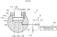
- FIG. 2A and FIG. 2B are a schematic configuration view and a schematic configuration diagram for illustrating the compression ratio varying mechanism V and the compression ratio control device 180, respectively.
- FIG. 2A is an extracted view for illustrating a coupling portion between the piston rod 114 and the crosshead pin 150.
- FIG. 2B is a functional block diagram for illustrating the compression ratio control device 180.
- a flat surface portion 152 is formed on an outer peripheral surface of the crosshead pin 150 on the piston 112 side. The flat surface portion 152 extends in a direction substantially perpendicular to the stroke direction of the piston 112.
- a pin hole 154 is formed in the crosshead pin 150.
- the pin hole 154 is opened in the flat surface portion 152.
- the pin hole 154 extends from the flat surface portion 152 toward the crankshaft 120 side (bottom side of FIG. 2 ) along the stroke direction.
- a cover member 160 is provided on the flat surface portion 152 of the crosshead pin 150.
- the cover member 160 is mounted to the flat surface portion 152 of the crosshead pin 150 by a fastening member 162.
- the cover member 160 covers the pin hole 154.
- a cover hole 160a passing in the stroke direction is provided in the cover member 160.
- the piston rod 114 includes a large-diameter portion 114a and a small-diameter portion 114b.
- An outer diameter of the large-diameter portion 114a is larger than an outer diameter of the small-diameter portion 114b.
- the large-diameter portion 114a is formed at the another end of the piston rod 114.
- the large-diameter portion 114a is inserted into the pin hole 154 of the crosshead pin 150.
- the small-diameter portion 114b is formed on the one end side of the piston rod 114 with respect to the large-diameter portion 114a.
- the small-diameter portion 114b is inserted into the cover hole 160a of the cover member 160.
- a hydraulic chamber 154a is formed inside the pin hole 154.
- the pin hole 154 is partitioned by the large-diameter portion 114a in the stroke direction.
- the hydraulic chamber 154a is a space defined on a bottom surface 154b side of the pin hole 154 partitioned by the large-diameter portion 114a.
- the compression ratio varying mechanism V includes a hydraulic pressure adjustment mechanism O.
- the hydraulic pressure adjustment mechanism O includes a hydraulic pipe 170, a hydraulic pump 172, a check valve 174, a branch pipe 176, and a selector valve 178.
- the hydraulic pipe 170 is connected to the another end of the oil passage 156.
- the hydraulic pump 172 communicates with the hydraulic pipe 170.
- the hydraulic pump 172 supplies working oil supplied from an oil tank (not shown) to the hydraulic pipe 170 based on an instruction from the compression ratio controller 182.
- the check valve 174 is provided between the hydraulic pump 172 and the oil passage 156. A flow of working oil flowing from the oil passage 156 side toward the hydraulic pump 172 is suppressed by the check valve 174.
- the working oil is forcibly fed into the hydraulic chamber 154a from the hydraulic pump 172 through the oil passage 156.
- the branch pipe 176 is connected to the hydraulic pipe 170 between the oil passage 156 and the check valve 174.
- the selector valve 178 is provided to the branch pipe 176.
- the selector valve 178 is, for example, an electromagnetic valve.
- the selector valve 178 is controlled to an open state or a closed state based on an instruction from the compression ratio controller 182.
- the selector valve 178 is closed during operation of the hydraulic pump 172.
- the selector valve 178 communicates with the oil tank (not shown) on a side of the selector valve 178 opposite to the oil passage 156.
- the discharged working oil is retained in the oil tank.
- the oil tank is configured to supply the working oil to the hydraulic pump 172.
- the large-diameter portion 114a is configured to slide on an inner peripheral surface of the pin hole 154 in the stroke direction in accordance with an oil amount of the working oil in the hydraulic chamber 154a. As a result, the piston rod 114 moves in the stroke direction. The piston 112 moves together with the piston rod 114. A top dead center position of the piston 112 becomes variable through the movement of the piston rod 114 in the stroke direction.
- the compression ratio varying mechanism V includes the hydraulic chamber 154a and the large-diameter portion 114a of the piston rod 114.
- the compression ratio varying mechanism V moves the top dead center position of the piston 112 so that the compression ratio is variable.
- the compression ratio varying mechanism V can vary the top dead center position and the bottom dead center position of the piston 112 in the cylinder 110 of the engine 100 through adjustment of the oil amount of the working oil to be supplied to the hydraulic chamber 154a.
- a space 154c on the cover member 160 side of the pin hole 154 partitioned by the large-diameter portion 114a may also be a hydraulic chamber. This hydraulic chamber may be used together with the hydraulic chamber 154a or may be used individually.
- the compression ratio control device 180 includes the compression ratio controller 182.
- the compression ratio control device 180 is formed of, for example, an engine control unit (ECU).
- the compression ratio control device 180 is formed of a central processing unit (CPU), a ROM storing programs and the like, a RAM serving as a work area, and the like, and is configured to control the entire engine 100.
- the compression ratio controller 182 is configured to control the hydraulic pump 172 and the selector valve 178 to move the top dead center position of the piston 112. In such a manner, the compression ratio controller 182 controls a geometrical compression ratio of the engine 100.
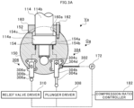
- FIG. 3A and FIG. 3B are respectively a schematic configuration view and a schematic configuration diagram for illustrating a compression ratio varying mechanism Va and a compression ratio control device 180a in a modification example.
- FIG. 3A is an extracted view for illustrating the coupling portion between the piston rod 114 and the crosshead pin 150 in the modification example.
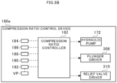
- FIG. 3B is a functional block diagram for illustrating the compression ratio control device 180a in the modification example.
- the compression ratio varying mechanism Va includes the hydraulic chamber 154a and the large-diameter portion 114a of the piston rod 114.
- the compression ratio varying mechanism Va includes a hydraulic pressure adjustment mechanism Oa.
- the hydraulic pressure adjustment mechanism Oa includes the hydraulic pump 172, a swiveling pipe 302, a plunger pump 304, a relief valve 306, a plunger driver 308, and a relief valve driver 310.
- the hydraulic pump 172 supplies the working oil supplied from the oil tank (not shown) to the swiveling pipe 302 based on an instruction from the compression ratio controller 182.
- the swiveling pipe 302 is a pipe configured to connect the hydraulic pump 172 and the plunger pump 304 to each other.
- the swiveling pipe 302 is configured to be able to swivel between the plunger pump 304 moving together with the crosshead pin 150 and the hydraulic pump 172.
- the plunger pump 304 is mounted to the crosshead pin 150.
- the plunger pump 304 includes a plunger 304a having a rod shape and a cylinder 304b having a tubular shape configured to slidably receive the plunger 304a.
- the plunger pump 304 moves as the crosshead pin 150 moves so that the plunger 304a comes into contact with the plunger driver 308.
- the plunger pump 304 is slid in the cylinder 304b through the contact of the plunger 304a with the plunger driver 308, thereby increasing the pressure of the working oil in the cylinder 304b to supply the working oil increased in pressure to the hydraulic chamber 154a.
- a first check valve 304c is provided in an opening provided at an end of the cylinder 304b on a discharge side for the working oil.
- a second check valve 304d is provided in an opening formed in a side peripheral surface of the cylinder 304b on a suction side.
- the plunger driver 308 is driven to a contact position, which is brought into contact with the plunger 304a and a non-contact position, which is not brought into contact with the plunger 304a based on instructions from the compression ratio controller 182.
- the plunger driver 308 comes into contact with the plunger 304a, to thereby press the plunger 304a toward the cylinder 304b.
- the first check valve 304c is closed when a valve body is biased toward an inside of the cylinder 304b.
- the first check valve 304c is closed, after the working oil has been supplied to the hydraulic chamber 154a, flowing back of the working oil into the cylinder 304b is suppressed.
- a pressure of the working oil in the cylinder 304b becomes equal to or more than a biasing force (opening pressure) of a biasing member of the first check valve 304c, the valve body of the first check valve 304c is pushed by the working oil, thereby being opened.
- the second check valve 304d is closed when a valve body is biased toward an outside of the cylinder 304b.
- the second check valve 304d is closed, after the working oil has been supplied to the cylinder 304b, the flowing back of the working oil into the hydraulic pump 172 is suppressed.
- the pressure of the working oil supplied from the hydraulic pump 172 becomes equal to or more than a biasing force (opening pressure) of a biasing member of the second check valve 304d
- the opening pressure of the first check valve 304c is set to be higher than the opening pressure of the second check valve 304d.
- the relief valve 306 is mounted to the crosshead pin 150.
- the relief valve 306 is connected to the hydraulic chamber 154a and the oil tank (not shown).
- the relief valve 306 includes a rod 306a having a rod shape, a main body 306b having a tubular shape, and a valve body 306c.
- the main body 306b is configured to slidably receive the rod 306a.
- An internal flow passage is formed inside the main body 306b.
- the working oil discharged from the hydraulic chamber 154a flows through the internal flow passage.
- the valve body 306c is arranged in the internal flow passage of the main body 306b.
- the relief valve 306 is configured to move as the crosshead pin 150 moves so that the rod 306a comes into contact with the relief valve driver 310.
- the relief valve driver 310 is driven to a contact position, which is brought into contact with the rod 306a and a non-contact position, which is not brought into contact with the rod 306a based on instructions from the compression ratio controller 182.
- the relief valve driver 310 comes into contact with the rod 306a, to thereby press the rod 306a toward the main body 306b.
- the rod 306a opens the valve body 306c.
- the valve body 306c is opened, the working oil stored in the hydraulic chamber 154a is returned to the oil tank.
- Each of the plunger driver 308 and the relief valve driver 310 includes a mechanism including a cam plate configured to perform operation control through, for example, a change in relative position to the plunger pump 304 or the relief valve 306. Moreover, each of the plunger driver 308 and the relief valve driver 310 includes a mechanism configured to use an actuator to drive the relative position of the cam plate.
- the compression ratio control device 180a includes the compression ratio controller 182.
- the compression ratio control device 180a is formed of, for example, an engine control unit (ECU).
- the compression ratio control device 180a is formed of a central processing unit (CPU), a ROM storing programs and the like, a RAM serving as a work area, and the like, and is configured to control the entire engine 100.
- the compression ratio controller 182 is configured to control the hydraulic pump 172, the plunger driver 308, and the relief valve driver 310 to move the top dead center position of the piston 112. In such a manner, the compression ratio controller 182 controls a geometrical compression ratio of the engine 100.
- FIG. 4 is a graph for showing an example of the pressure in the cylinder 110 measured by the pressure detection sensor 190.
- a vertical axis represents the pressure (cylinder internal pressure) in the cylinder 110
- a horizontal axis represents a crank angle.
- the mixture (the air and the fuel) in the cylinder 110 is compressed by the piston 112, and the temperature and the pressure in the cylinder 110 increase (compression stroke).
- the crank angle reaches a point A before the crank angle reaches the top dead center from the bottom dead center, the mixture in the cylinder 110 is combusted, and the combustion gas is expanded by heat generated by the combustion (the combustion stroke and the expansion stroke).
- a force for pushing down the piston 112 is generated through an increase in pressure by the expansion of the combustion gas.
- compression pressure Pcomp a pressure in the compression stroke in which the crank angle is before the point A
- combustion pressure P a pressure in the combustion stroke and the expansion stroke in which the crank angle is after the point A
- combustion pressure P a pressure in the combustion stroke and the expansion stroke in which the crank angle is after the point A
- maximum combustion pressure Pmax the maximum pressure of the combustion pressure P
- the maximum combustion pressure Pmax is the maximum pressure in the cylinder 110 measured by the pressure detection sensor 190 in one combustion cycle.
- a broken line of FIG. 4 indicates a compression pressure after the point A estimated from the pressure measured in the compression stroke.
- a point B of FIG. 4 indicates a peak position (peak value) of the estimated compression pressure.
- a point C of FIG. 4 indicates a peak position (peak value) of the combustion pressure P, that is, a position of the maximum combustion pressure Pmax.
- the cylinder-internal-pressure upper limit value (combustion pressure upper limit value) is defined for the engine 100. Therefore, the engine 100 needs to suppress the maximum combustion pressure Pmax so as to be equal to or less than the cylinder-internal-pressure upper limit value.
- the maximum combustion pressure Pmax changes in accordance with a scavenging pressure Ps, which is a pressure of the active gas supplied to the combustion chamber 128. Specifically, as the scavenging pressure Ps becomes larger, the maximum combustion pressure Pmax becomes larger. As the scavenging pressure Ps becomes smaller, the maximum combustion pressure Pmax becomes smaller.
- the scavenging pressure Ps changes in accordance with engine load. Specifically, as the engine load (for example, the engine rotation speed) becomes larger, the scavenging pressure Ps becomes larger. As the engine load becomes smaller, the scavenging pressure Ps becomes smaller. Consequently, the maximum combustion pressure Pmax reaches the highest value at an engine full load (100% load) at which the scavenging pressure Ps becomes larger to the highest value, that is, the engine load becomes larger to the highest value. Therefore, the compression ratio of the engine 100 is usually set so that the maximum combustion pressure Pmax at the engine full load is the cylinder-internal-pressure upper limit value when the compression ratio of the combustion chamber 128 is fixed.
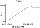
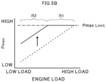
- FIG. 5A and FIG. 5B are graphs showing a relationship between the engine load and the maximum combustion pressure Pmax.
- a vertical axis represents the maximum combustion pressure Pmax
- a horizontal axis represents the engine load.
- FIG. 5A is a graph for showing a relationship between the engine load and the maximum combustion pressure Pmax when the compression ratio of the combustion chamber 128 is fixed, not according to the invention.
- FIG. 5B is a graph for showing the relationship between the engine load and the maximum combustion pressure Pmax when the compression ratio of the combustion chamber 128 is fixed and when the compression ratio is variable.
- a one-dot chain line indicates the cylinder-internal-pressure upper limit value Pmax Limit.
- a solid line of FIG. 5A indicates the maximum combustion pressure Pmax changing in accordance with the engine load when the compression ratio of the combustion chamber 128 is fixed.
- the maximum combustion pressure Pmax is the cylinder-internal-pressure upper limit value Pmax Limit in the engine full load state.
- a fuel consumption rate can be reduced (that is, the fuel efficiency can be improved). Therefore, the fuel efficiency is improved in the engine full load state in which the maximum combustion pressure Pmax is the cylinder-internal-pressure upper limit value Pmax Limit.
- the compression ratio controller 182 controls the compression ratio of the combustion chamber 128 (compression ratio varying mechanism V) so that the maximum combustion pressure Pmax approaches the cylinder-internal-pressure upper limit value Pmax Limit set in advance.
- the compression ratio controller 182 can acquire the detection value (the cylinder internal pressure including the maximum combustion pressure Pmax) output from the pressure detection sensor 190.
- the compression ratio controller 182 compares the maximum combustion pressure Pmax detected by the pressure detection sensor 190 and the cylinder-internal-pressure upper limit value Pmax Limit with each other, and then controls the compression ratio so that the maximum combustion pressure Pmax approaches the cylinder-internal-pressure upper limit value Pmax Limit.
- the compression ratio controller 182 controls the compression ratio varying mechanism V so that the compression ratio of the combustion chamber 128 becomes variable between a compression ratio ⁇ 0 and a compression ratio ⁇ n.
- the compression ratio ⁇ 0 is a compression ratio at which the compression ratio of the combustion chamber 128 is the lowest.
- the compression ratio ⁇ n is a compression ratio at which the compression ratio of the combustion chamber 128 is the highest.
- a solid line of FIG. 5B indicates the maximum combustion pressure Pmax, which changes in accordance with the engine load when the compression ratio of the combustion chamber 128 is variable in this embodiment.
- the compression ratio controller 182 controls the compression ratio varying mechanism V so that the compression ratio of the combustion chamber 128 is a lowest compression ratio ⁇ 0 in the engine full load state.
- the maximum combustion pressure Pmax is the cylinder-internal-pressure upper limit value Pmax Limit.
- a broken line of FIG. 5B indicates the maximum combustion pressure Pmax, which changes in accordance with the engine load when the compression ratio of the combustion chamber 128 is fixed to the lowest compression ratio ⁇ 0.
- the compression ratio controller 182 controls the compression ratio varying mechanism V so that the compression ratio of the combustion chamber 128 is a compression ratio larger than the lowest compression ratio ⁇ 0 in a load state in which a load is smaller than the load in the engine full load state.
- the maximum combustion pressure Pmax changes in accordance with the scavenging pressure Ps, but also changes in accordance with the compression ratio of the combustion chamber 128. Specifically, as the compression ratio becomes larger, the maximum combustion pressure Pmax becomes larger. As the compression ratio becomes smaller, the maximum combustion pressure Pmax becomes smaller.
- the maximum combustion pressure Pmax can be made larger through changing the compression ratio of the combustion chamber 128 to a compression ratio larger than the lowest compression ratio ⁇ 0.
- the maximum combustion pressure Pmax can be caused to approach the cylinder-internal-pressure upper limit value Pmax Limit also in the load state in which the load is smaller than the load in the engine full load state.
- the compression ratio controller 182 varies the compression ratio of the combustion chamber 128 so that the maximum combustion pressure Pmax is maintained to the cylinder-internal-pressure upper limit value Pmax Limit even when the engine load becomes smaller.
- An engine load region R1 shown in FIG. 5B is a range in which the maximum combustion pressure Pmax can be maintained to the cylinder-internal-pressure upper limit value Pmax Limit through changing the compression ratio of the combustion chamber 128 in the range from the lowest compression ratio ⁇ 0 to the highest compression ratio ⁇ n.
- the compression ratio controller 182 can obtain a larger compression ratio when the compression ratio of the combustion chamber 128 is variable (the solid line of FIG. 5B ) than the compression ratio when the compression ratio of the combustion chamber 128 is fixed (the broken line of FIG. 5B ). As described above, as the compression ratio becomes larger, the maximum combustion pressure Pmax becomes larger.
- the maximum combustion pressure Pmax when the compression ratio of the combustion chamber 128 is set to a compression ratio larger than the lowest compression ratio ⁇ 0 can be made larger than the maximum combustion pressure Pmax when the compression ratio is set to the lowest compression ratio ⁇ 0 (the broken line of FIG. 5B ).
- the compression ratio controller 182 increases the compression ratio of the combustion chamber 128 as much as possible in the range in which the maximum combustion pressure Pmax does not exceed the cylinder-internal-pressure upper limit value Pmax Limit in the engine load region R1, thereby being able to improve the fuel efficiency.
- An engine load region R2 shown in FIG. 5B is a range in which the maximum combustion pressure Pmax is less than the cylinder-internal-pressure upper limit value Pmax Limit even when the compression ratio of the combustion chamber 128 is set to the highest compression ratio ⁇ n.
- the engine load region R1 is an engine load region including the engine full load.
- the engine load region R2 is a load region in which the load is smaller than the load in the engine load region R1.
- the maximum combustion pressure Pmax is less than the cylinder-internal-pressure upper limit value Pmax Limit whether the compression ratio of the combustion chamber 128 is fixed (broken line) or variable (solid line).
- the compression ratio controller 182 can achieve the larger compression ratio ⁇ n than the compression ratio when the compression ratio of the combustion chamber 128 is fixed (broken line).
- the compression ratio controller 182 increases the compression ratio of the combustion chamber 128 as much as possible, to thereby improve the fuel economy also in the engine load region R2.
- the compression ratio controller 182 controls the compression ratio so that the compression ratio is the highest compression ratio in the range in which the maximum combustion pressure Pmax is less than the cylinder-internal-pressure upper limit value Pmax Limit. Specifically, the compression ratio controller 182 controls the compression ratio so as to be maintained to the highest compression ratio ⁇ n in the case in which the maximum combustion pressure Pmax is less than the cylinder-internal-pressure upper limit value Pmax Limit when the compression ratio is the highest compression ratio ⁇ n.
- FIG. 6A , FIG. 6B , FIG. 6C , FIG. 6D , and FIG. 6E are graphs for showing performance of the engine 100 according to this embodiment.
- FIG. 6A is a graph for showing a relationship between a fuel consumption rate (fuel efficiency) and the engine load in the engine load region R1 shown in FIG. 5B .
- a vertical axis represents the fuel consumption rate
- a horizontal axis represents the engine load.
- engine loads becomes smaller in the order of Ea, Eb, Ec, Ed, and Ee. That is, a relationship among the engine loads Ea, Eb, Ec, Ed, and Ee is represented as Ea>Eb>Ec>Ed>Ed.
- the engine load Ea indicates an engine full load (100% load).
- the engine loads Ea, Eb, Ec, Ed, and Ee of FIG. 6B to FIG. 6E are also defined as the engine loads of FIG. 6A .
- a broken line indicates the lowest fuel consumption rate at which the fuel consumption rate is the lowest.
- FIG. 6B is a graph for showing a relationship between the maximum combustion pressure Pmax and the engine load in the engine load region R1 shown in FIG. 5B .
- a vertical axis represents the maximum combustion pressure Pmax
- a horizontal axis represents the engine load.
- a one-dot chain line indicates the cylinder-internal-pressure upper limit value Pmax Limit.
- the cylinder-internal-pressure upper limit value is a constant value independent of the engine load.
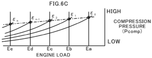
- FIG. 6C is a graph for showing a relationship between the compression pressure Pcomp and the engine load in the engine load region R1 shown in FIG. 5B .
- a vertical axis represents the compression pressure Pcomp
- a horizontal axis represents the engine load.
- the compression pressure Pcomp is the estimated peak value of the compression pressure such as the point B of FIG. 4 .
- a one-dot chain line indicates a target value (hereinafter referred to as "target compression pressure") of the estimated peak value of the compression pressure.
- the maximum combustion pressure Pmax can be caused to approach the cylinder-internal-pressure upper limit value Pmax Limit by causing the peak value of the compression pressure Pcomp to approach the target compression pressure.
- the maximum combustion pressure Pmax is the cylinder-internal-pressure upper limit value Pmax Limit.
- the target compression pressure changes in accordance with the engine load, and is thus not a constant value.
- the target compression pressure is a value that becomes smaller as the engine load becomes smaller, and becomes larger as the engine load becomes larger. This is because a difference ⁇ between the peak value of the compression pressure Pcomp indicated by the point B of FIG. 4 and the peak value (maximum combustion pressure Pmax) of the combustion pressure P indicated by the point C of FIG. 4 becomes larger as the engine load becomes larger. Even when the difference ⁇ becomes larger as the engine load becomes larger, the maximum combustion pressure Pmax can be a constant value independent of the engine load through increasing the target compression pressure as the engine load becomes larger.
- FIG. 6D is a graph for showing a relationship between the scavenging pressure Ps and the engine load in the engine load region R1 shown in FIG. 5B .
- a vertical axis represents the scavenging pressure Ps
- the horizontal axis represents the engine load.
- the scavenging pressure Ps becomes larger as the engine load becomes larger, and becomes smaller as the engine load becomes smaller.
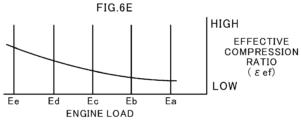
- FIG. 6E is a graph for showing a relationship between an effective compression ratio ⁇ ef and the engine load in the engine load region R1 shown in FIG. 5B .
- a vertical axis represents the effective compression ratio ⁇ ef
- the horizontal axis represents the engine load.
- the effective compression ratio ⁇ ef becomes smaller as the engine load becomes larger, and becomes larger as the engine load becomes smaller.
- the effective compression ratio ⁇ ef is an actual compression ratio of the combustion chamber 128, and is indicated by a ratio between a volume in the cylinder 110 at a moment when the scavenging ports 110a are closed and a volume of the combustion chamber 128 when the piston 112 reaches the top dead center.
- the compression ratio controller 182 changes the compression ratio of the combustion chamber 128 in the order of compression ratios of ⁇ 0, ⁇ 1, ⁇ 2, ⁇ n-1, and ⁇ n.
- the compression ratio is a value which becomes larger in the order of ⁇ 0, ⁇ 1, ⁇ 2, ⁇ n-1, and ⁇ n. That is, a relationship among the compression ratios ⁇ 0, ⁇ 1, ⁇ 2, ⁇ n-1, and ⁇ n is represented as ⁇ 0 ⁇ 1 ⁇ 2 ⁇ n-1 ⁇ n.
- the compression ratio controller 182 sets the compression ratio of the combustion chamber 128 to the compression ratio ⁇ 0 at the engine load Ea (engine full load).
- the maximum combustion pressure Pmax can be brought to the cylinder-internal-pressure upper limit value Pmax Limit by setting the compression ratio to the compression ratio ⁇ 0 at the engine load Ea.
- the compression ratio controller 182 sets the compression ratio of the combustion chamber 128 to the compression ratio ⁇ 1 at the engine load Eb.
- the maximum combustion pressure Pmax can be brought to the cylinder-internal-pressure upper limit value Pmax Limit by setting the compression ratio to the compression ratio ⁇ 1 at the engine load Eb.
- the compression ratio controller 182 sets the compression ratio of the combustion chamber 128 to the compression ratio ⁇ 2 at the engine load Ec.
- the maximum combustion pressure Pmax can be brought to the cylinder-internal-pressure upper limit value Pmax Limit by setting the compression ratio to the compression ratio ⁇ 2 at the engine load Ec.
- the compression ratio controller 182 sets the compression ratio of the combustion chamber 128 to the compression ratio ⁇ n-1 at the engine load Ed.
- the maximum combustion pressure Pmax can be brought to the cylinder-internal-pressure upper limit value Pmax Limit by setting the compression ratio to the compression ratio ⁇ n-1 at the engine load Ed.
- the compression ratio controller 182 sets the compression ratio of the combustion chamber 128 to the compression ratio ⁇ n at the engine load Ee.
- the maximum combustion pressure Pmax can be brought to the cylinder-internal-pressure upper limit value Pmax Limit by setting the compression ratio to the compression ratio ⁇ n at the engine load Ee.
- the compression ratio controller 182 controls the compression ratio of the combustion chamber 128 so that the maximum combustion pressure Pmax approaches the cylinder-internal-pressure upper limit value Pmax Limit set in advance.
- the compression ratio controller 182 increases the compression ratio as the engine load becomes smaller from the engine full load state.
- the maximum combustion pressure Pmax can be caused to approach the cylinder-internal-pressure upper limit value Pmax Limit as shown in FIG. 6B .
- the fuel consumption rate can be minimized (that is, the fuel efficiency can be improved) at each of the engine loads Ea to Ee.
- FIG. 7 is a flowchart for illustrating control processing for the compression ratio by the compression ratio controller 182.
- the compression ratio controller 182 derives the current cylinder internal pressure based on the signal output from the pressure detection sensor 190 (Step S102). Then, the compression ratio controller 182 determines whether or not the maximum combustion pressure Pmax is smaller than the cylinder-internal-pressure upper limit value Pmax Limit (Step S104). When the maximum combustion pressure Pmax is smaller than the cylinder-internal-pressure upper limit value Pmax Limit (YES in Step S104), the compression ratio controller 182 proceeds to Step S106. Meanwhile, when the maximum combustion pressure Pmax is equal to or more than the cylinder-internal-pressure upper limit value Pmax Limit (NO in Step S104), the compression ratio controller 182 proceeds to Step S110.
- Step S104 the compression ratio controller 182 controls the compression ratio varying mechanism V so as to increase the compression ratio of the combustion chamber 128 (Step S106).
- the compression ratio controller 182 determines whether or not the compression ratio of the combustion chamber 128 is the maximum compression ratio ⁇ n (Step S108).
- the compression ratio controller 182 proceeds to Step S116.
- the compression ratio controller 182 returns to Step S102, and again executes the processing in Step S102 to Step S104.
- Step S110 determines whether or not the maximum combustion pressure Pmax is larger than the cylinder-internal-pressure upper limit value Pmax Limit (Step S110).
- the compression ratio controller 182 proceeds to Step S112.
- the maximum combustion pressure Pmax is equal to or less than the cylinder-internal-pressure upper limit value Pmax Limit, that is, when the maximum combustion pressure Pmax is the cylinder-internal-pressure upper limit value Pmax Limit (NO in Step S110)
- the compression ratio controller 182 proceeds to Step S116.
- the compression ratio controller 182 controls the compression ratio varying mechanism V so as to decrease the compression ratio of the combustion chamber 128 (Step S112). After the compression ratio controller 182 decreases the compression ratio of the combustion chamber 128, the compression ratio controller 182 determines whether or not the compression ratio of the combustion chamber 128 is the minimum compression ratio ⁇ 0 (Step S114). When the compression ratio of the combustion chamber 128 is the minimum compression ratio ⁇ 0 (YES in Step S114), the compression ratio controller 182 proceeds to Step S116. When the compression ratio of the combustion chamber 128 is not the minimum compression ratio ⁇ 0 (NO in Step S114), the compression ratio controller 182 returns to Step S102, and again executes the processing in Step S102, Step S104, and Step S110.
- Step S116 the compression ratio controller 182 controls the compression ratio varying mechanism V so that the compression ratio in the combustion chamber 128 is maintained (Step S116), and finishes the control processing for the compression ratio.
- the compression ratio controller 182 changes the compression ratio in accordance with the maximum combustion pressure Pmax measured by the pressure detection sensor 190.
- the maximum combustion pressure Pmax is not required to be measured by the pressure detection sensor 190.
- the compression ratio controller 182 may estimate the maximum combustion pressure Pmax based on the scavenging pressure Ps measured by the scavenging pressure detection sensor 186 in place of the pressure detection sensor 190.
- the compression ratio controller 182 may estimate the maximum combustion pressure Pmax based on the scavenging pressure Ps, the compression ratio, and a specific heat ratio.
- the compression ratio controller 182 may compare the estimated maximum combustion pressure Pmax and the cylinder-internal-pressure upper limit value Pmax Limit with each other, and may then control the compression ratio so that the maximum combustion pressure Pmax approaches the cylinder-internal-pressure upper limit value Pmax Limit.
- the compression ratio controller 182 may vary the compression ratio in accordance with the compression pressure Pcomp.
- the compression ratio controller 182 estimates the peak value of the compression pressure Pcomp from the cylinder internal pressure measured by the pressure detection sensor 190.
- the compression ratio controller 182 includes a ROM storing, in advance, a map indicating a target compression pressure corresponding to the engine load or the engine rotation speed.
- the compression ratio controller 182 refers to the map stored in the ROM, thereby being capable of varying the compression ratio to a compression ratio at which the estimated peak value of the compression pressure is the target compression pressure.
- the compression ratio controller 182 varies the compression ratio to the compression ratio at which the peak value of the compression pressure Pcomp is the target compression pressure so that the maximum combustion pressure Pmax can be caused to approach the cylinder-internal-pressure upper limit value Pmax Limit at each engine load.
- the compression ratio controller 182 may estimate the maximum combustion pressure Pmax from the estimated peak value of the compression pressure and the difference ⁇ between the above-mentioned point B and point C of FIG. 4 .
- the compression ratio controller 182 includes a ROM storing, in advance, a map indicating a difference ⁇ corresponding to the engine load or the engine rotation speed.
- the compression ratio controller 182 refers to the map stored in the ROM, thereby being capable of estimating the maximum combustion pressure Pmax from the estimated peak value of the compression pressure and the difference ⁇ .
- the compression ratio controller 182 may compare the estimated maximum combustion pressure Pmax and the cylinder-internal-pressure upper limit value Pmax Limit with each other, and may then control the compression ratio so that the maximum combustion pressure Pmax approaches the cylinder-internal-pressure upper limit value Pmax Limit.
- the engine 100 includes the detectors (for example, the rotation speed detection sensor 184 and the pressure detection sensor 190) configured to detect the signals correlating with at least one of the engine load or the maximum combustion pressure in the combustion chamber 128.
- the compression ratio controller 182 can control the compression ratio so that the maximum combustion pressure Pmax approaches the cylinder-internal-pressure upper limit value Pmax Limit set in advance based on the signals acquired from the detectors.
- the engine load may vary even when the engine rotation speed is the same.
- a fixed-pitch propeller and a variable-pitch propeller are given as the driven member driven by the engine 100. While the fixed-pitch propeller has a fixed angle of blades, the variable-pitch propeller can change the angle of the blades. Therefore, even when the variable-pitch propeller has the same rotation speed as the rotation speed of the fixed-pitch propeller, the variable-pitch propeller may apply a different engine load in accordance with the angle of the blades.
- the compression ratio controller 182 can control the compression ratio so that the maximum combustion pressure Pmax approaches the cylinder-internal-pressure upper limit value Pmax Limit through use of the above-mentioned method.
- the compression ratio controller 182 is not be able to control the compression ratio so that the maximum combustion pressure Pmax approaches the cylinder-internal-pressure upper limit value Pmax Limit through use of the above-mentioned method.
- the compression ratio controller 182 may derive, for example, the maximum combustion pressure Pmax based on the angle of the blades of the variable-pitch propeller and the engine rotation speed. Then, the compression ratio controller 182 may compare the derived maximum combustion pressure Pmax and the cylinder-internal-pressure upper limit value Pmax Limit with each other, and may then control the compression ratio so that the maximum combustion pressure Pmax approaches the cylinder-internal-pressure upper limit value Pmax Limit.
- the compression ratio controller 182 can acquire information on the angle of the blades of the variable-pitch propeller VP from an angle detection sensor 192 (detector, see FIG. 2B and FIG. 3B ) configured to be able to detect the angle of the blades of the variable-pitch propeller VP.
- the compression ratio controller 182 includes a ROM storing, in advance, a map indicating the maximum combustion pressure Pmax corresponding to the angle of the blades of the variable-pitch propeller VP and the engine rotation speed.
- the compression ratio controller 182 refers to the map stored in the ROM, thereby being capable of deriving the maximum combustion pressure Pmax from the current angle of the blades of the variable-pitch propeller VP and the engine rotation speed.
- the map stored in the ROM may be a map indicating a compression ratio corresponding to the angle of the blades of the variable-pitch propeller VP and the engine rotation speed.
- the compression ratio controller 182 refers to the map stored in the ROM, thereby being capable of deriving the compression ratio from the current angle of the blades of the variable-pitch propeller VP and the engine rotation speed.
- the compression ratio controller 182 can derive the engine load based on the angle of the blades of the variable-pitch propeller VP, the engine rotation speed, and the fuel injection amount. Consequently, the map stored in the ROM may be the above-mentioned map (for example, the map indicating the compression ratio corresponding to the engine load).
- the type of the engine is not limited to the two-cycle type, the uniflow scavenging type, and the crosshead type. It is only required that the present disclosure be applied to an engine.
- the configuration is not limited to this example, and a liquid fuel may be supplied to the inside of the cylinder 110 (combustion chamber 128).
- the engine 100 may be, for example, of a dual fuel type, which chooses a gas fuel or a liquid fuel to be used.
- the engine 100 is not limited to an engine for a boat, and may be an engine for, for example, an automobile.
- the present disclosure can be applied to the compression ratio control device and the engine.
Landscapes
- Engineering & Computer Science (AREA)
- Chemical & Material Sciences (AREA)
- Combustion & Propulsion (AREA)
- Mechanical Engineering (AREA)
- General Engineering & Computer Science (AREA)
- Aviation & Aerospace Engineering (AREA)
- Ocean & Marine Engineering (AREA)
- Output Control And Ontrol Of Special Type Engine (AREA)
- Combined Controls Of Internal Combustion Engines (AREA)
Description
- The present disclosure relates to a compression ratio control device and an engine. This application claims the benefit of priority to
Japanese Patent Application No. 2018-063299 filed on March 28, 2018 - In a crosshead type engine described in
Patent Literature 1, a hydraulic mechanism is provided between a piston rod and a crosshead pin. InPatent Literature 1, the hydraulic mechanism is operated to cause the piston rod to move up and down so that a compression ratio of the crosshead type engine may be varied. Patent Literature 4 discloses a variable compression ratio control device according to the preamble ofclaim 1.Patent Literature 2, 3, 5 and 6 disclose further prior art. -
- Patent Literature 1:
JP 2014 - 020 375 A - Patent Literature 2:
US 7 036 467 B2 - Patent Literature 3:
WO 2007 / 092 168 A2 - Patent Literature 4:
US 4 834 031 A - Patent Literature 5:
US 2003 / 051 685 A1 - Patent Literature 6:
JP S62 - 032 213 A - In
Patent Literature 1, fuel efficiency is improved by changing the compression ratio, for example, when a supplied fuel is changed from diesel oil to gas. However, development of a technology capable of further improving the fuel efficiency of an engine is longed for. - The present disclosure has an object to provide a compression ratio control device capable of improving fuel efficiency of an engine, and to provide an engine.
- The above-mentioned problem is solved by a compression ratio control device according to
claim 1. Advantageous embodiments are disclosed in the dependent claims. The problem is also solved by an engine according to claim 7, which comprises the compression ratio control device. - According to the compression ratio control device and the engine of the present disclosure, it is possible to improve the fuel efficiency of the engine.
-
-
FIG. 1 is an explanatory view for illustrating an overall configuration of an engine. -
FIG. 2A is an extracted view for illustrating a coupling portion between a piston rod and a crosshead pin. -
FIG. 2B is a functional block diagram for illustrating a compression ratio control device. -
FIG. 3A is an extracted view for illustrating the coupling portion between the piston rod and the crosshead pin in a modification example. -
FIG. 3B is a functional block diagram for illustrating the compression ratio control device in the modification example. -
FIG. 4 is a graph for showing an example of a pressure in a cylinder measured by a pressure detection sensor. -
FIG. 5A is a graph for showing a relationship between an engine load and the maximum combustion pressure when a compression ratio of a combustion chamber is fixed, not according to the invention. -
FIG. 5B is a graph for showing the relationship between the engine load and the maximum combustion pressure when the compression ratio of the combustion chamber is fixed and when the compression ratio is variable. -
FIG. 6A is a graph for showing a relationship between a fuel consumption rate (fuel efficiency) and the engine load in an engine load region shown inFIG. 5B . -
FIG. 6B is a graph for showing a relationship between the maximum combustion pressure and the engine load in the engine load region shown inFIG. 5B . -
FIG. 6C is a graph for showing a relationship between a compression pressure and the engine load in the engine load region shown inFIG. 5B . -
FIG. 6D is a graph for showing a relationship between a scavenging pressure and the engine load in the engine load region shown inFIG. 5B . -
FIG. 6E is a graph for showing a relationship between an effective compression ratio and the engine load in the engine load region shown inFIG. 5B . -
FIG. 7 is a flowchart for illustrating control processing for a compression ratio by a compression ratio controller. - Now, with reference to the attached drawings, an embodiment of the present disclosure is described in detail. The dimensions, materials, and other specific numerical values represented in the embodiment are merely examples used for facilitating the understanding of the disclosure, and do not limit the present disclosure otherwise particularly noted. Elements having substantially the same functions and configurations herein and in the drawings are denoted by the same reference symbols to omit redundant description thereof. Further, illustration of elements with no direct relationship to the present disclosure is omitted.
-
FIG. 1 is an explanatory view for illustrating an overall configuration of anengine 100. As illustrated inFIG. 1 , theengine 100 includes acylinder 110, apiston 112, apiston rod 114, acrosshead 116, aconnecting rod 118, acrankshaft 120, aflywheel 122, acylinder cover 124, anexhaust valve cage 126, acombustion chamber 128, anexhaust valve 130, an exhaustvalve drive device 132, anexhaust pipe 134, ascavenge reservoir 136, acooler 138, and acylinder jacket 140. - The
piston 112 is provided in thecylinder 110. Thepiston 112 is configured to reciprocate inside thecylinder 110. One end of thepiston rod 114 is mounted to thepiston 112. Acrosshead pin 150 of thecrosshead 116 is coupled to another end of thepiston rod 114. Thecrosshead 116 is configured to reciprocate together with thepiston 112. A movement of thecrosshead 116 in a right-and-left direction (a direction perpendicular to a stroke direction of the piston 112) ofFIG. 1 is restricted by a guide shoe 116a. - The
crosshead pin 150 is axially supported by a crosshead bearing 118a provided at one end of the connectingrod 118. Thecrosshead pin 150 is configured to support one end of the connectingrod 118. Another end of thepiston rod 114 and the one end of the connectingrod 118 are connected to each other through intermediation of thecrosshead 116. - Another end of the connecting
rod 118 is coupled to thecrankshaft 120. Thecrankshaft 120 is rotatable with respect to the connectingrod 118. When thecrosshead 116 reciprocates as thepiston 112 reciprocates, thecrankshaft 120 rotates. A rotationspeed detection sensor 184 is provided in theengine 100. The rotationspeed detection sensor 184 is provided in a vicinity of thecrankshaft 120. The rotationspeed detection sensor 184 is configured to detect an angle of thecrankshaft 120, to thereby detect the engine rotation speed. - The
flywheel 122 is mounted to thecrankshaft 120. Rotations of thecrankshaft 120 and the like are stabilized by an inertia of theflywheel 122. Thecylinder cover 124 is provided at a top end of thecylinder 110. Theexhaust valve cage 126 is inserted through thecylinder cover 124. - One end of the
exhaust valve cage 126 faces thepiston 112. Anexhaust port 126a is opened at the one end of theexhaust valve cage 126. Theexhaust port 126a is opened to thecombustion chamber 128. Theexhaust chamber 128 is formed inside thecylinder 110 so as to be surrounded by thecylinder cover 124, thecylinder 110, and thepiston 112. - A valve body of the
exhaust valve 130 is located in thecombustion chamber 128. The exhaustvalve drive device 132 is mounted to a rod portion of theexhaust valve 130. The exhaustvalve drive device 132 is arranged in theexhaust valve cage 126. The exhaustvalve drive device 132 moves theexhaust valve 130 in a stroke direction of thepiston 112. - When the
exhaust valve 130 moves toward thepiston 112 side, theexhaust port 126a is opened. When theexhaust port 126a is opened, an exhaust gas generated in thecylinder 110 after the combustion is discharged from theexhaust port 126a. After the exhaust gas is discharged, when theexhaust valve 130 moves toward theexhaust valve cage 126 side, theexhaust port 126a is closed. - The
exhaust pipe 134 is mounted to theexhaust valve cage 126 and a turbocharger C. An inside of theexhaust pipe 134 communicates with theexhaust port 126a and a turbine of the turbocharger C. The exhaust gas discharged from theexhaust port 126a is supplied to the turbine of the turbocharger C through theexhaust pipe 134, and is then discharged to the outside. - An active gas is pressurized by a compressor of the turbocharger C. In this state, the active gas is, for example, air. The pressurized active gas is cooled by the cooler 138 in the
scavenge reservoir 136. A bottom end of thecylinder 110 is surrounded by thecylinder jacket 140. Ascavenge chamber 140a is formed inside thecylinder jacket 140. The active gas after the cooling is forcibly fed into thescavenge chamber 140a. -
Scavenging ports 110a are formed on a bottom end side of thecylinder 110. The scavengingport 110a is a hole passing from an inner peripheral surface to an outer peripheral surface of thecylinder 110. A plurality of scavengingports 110a are formed at intervals in a circumferential direction of thecylinder 110. - When the
piston 112 moves toward a bottom dead center position side with respect to the scavengingports 110a, the active gas is sucked from the scavengingports 110a into thecylinder 110 by a pressure difference between thescavenge chamber 140a and the inside of thecylinder 110. A scavengingpressure detection sensor 186 is provided in thescavenge chamber 140a. The scavengingpressure detection sensor 186 is configured to detect a scavenging pressure, which is a pressure of the active gas supplied into the cylinder 110 (combustion chamber 128). - A gas fuel injection valve (not shown) is provided in a vicinity of the scavenging
ports 110a, or a portion of thecylinder 110 from the scavengingports 110a to thecylinder cover 124. The fuel gas is injected from the gas fuel injection valve, and then flows into thecylinder 110. - A pilot injection valve (not shown) is provided in the
cylinder cover 124. An appropriate amount of fuel oil is injected from the pilot injection valve into thecombustion chamber 128. The fuel oil is vaporized, ignited, and combusted through heat of thecombustion chamber 128, thereby increasing the temperature in thecombustion chamber 128. Mixture of the fuel gas and the active gas compressed by thepiston 112 is ignited by the heat of thecombustion chamber 128, and is combusted. Thepiston 112 is configured to reciprocate through an expansion pressure generated by the combustion of the fuel gas (mixture). An injectionamount detection sensor 188 is provided in thecylinder cover 124. The injectionamount detection sensor 188 is configured to detect an injection amount of the fuel supplied from the gas fuel injection valve (not shown) into thecombustion chamber 128. Moreover, apressure detection sensor 190 is provided in thecylinder cover 124. Thepressure detection sensor 190 is configured to detect a pressure in the cylinder 110 (combustion chamber 128). - The rotation
speed detection sensor 184, the scavengingpressure detection sensor 186, the fuel injectionamount detection sensor 188, and thepressure detection sensor 190 are connected to acompression ratio controller 182 described later, and are configured to output detection values (detection signals) to thecompression ratio controller 182. InFIG. 1 , flows of the signals are indicated by broken line arrows. - In this case, the fuel gas is produced by, for example, gasifying a liquefied natural gas (LNG). However, the fuel gas is not limited to those produced by gasifying the LNG, and there may also be used fuel gas produced by gasifying, for example, a liquefied petroleum gas (LPG), a light oil, or a heavy oil.
- A compression ratio varying mechanism V is provided for the
engine 100. A compressionratio control device 180 configured to control a compression ratio of thecombustion chamber 128 is provided for theengine 100. The compressionratio control device 180 includes detectors such as the rotationspeed detection sensor 184, the scavengingpressure detection sensor 186, the injectionamount detection sensor 188, and thepressure detection sensor 190, and thecompression ratio controller 182. Thecompression ratio controller 182 is configured to control the compression ratio varying mechanism V based on the signals obtained from the detectors such as the rotationspeed detection sensor 184, the scavengingpressure detection sensor 186, the injectionamount detection sensor 188, and thepressure detection sensor 190. A detailed description is now given of the compression ratio varying mechanism V and the compressionratio control device 180. -
FIG. 2A andFIG. 2B are a schematic configuration view and a schematic configuration diagram for illustrating the compression ratio varying mechanism V and the compressionratio control device 180, respectively.FIG. 2A is an extracted view for illustrating a coupling portion between thepiston rod 114 and thecrosshead pin 150.FIG. 2B is a functional block diagram for illustrating the compressionratio control device 180. As illustrated inFIG. 2A , aflat surface portion 152 is formed on an outer peripheral surface of thecrosshead pin 150 on thepiston 112 side. Theflat surface portion 152 extends in a direction substantially perpendicular to the stroke direction of thepiston 112. - A
pin hole 154 is formed in thecrosshead pin 150. Thepin hole 154 is opened in theflat surface portion 152. Thepin hole 154 extends from theflat surface portion 152 toward thecrankshaft 120 side (bottom side ofFIG. 2 ) along the stroke direction. - A
cover member 160 is provided on theflat surface portion 152 of thecrosshead pin 150. Thecover member 160 is mounted to theflat surface portion 152 of thecrosshead pin 150 by afastening member 162. Thecover member 160 covers thepin hole 154. Acover hole 160a passing in the stroke direction is provided in thecover member 160. - The
piston rod 114 includes a large-diameter portion 114a and a small-diameter portion 114b. An outer diameter of the large-diameter portion 114a is larger than an outer diameter of the small-diameter portion 114b. The large-diameter portion 114a is formed at the another end of thepiston rod 114. The large-diameter portion 114a is inserted into thepin hole 154 of thecrosshead pin 150. The small-diameter portion 114b is formed on the one end side of thepiston rod 114 with respect to the large-diameter portion 114a. The small-diameter portion 114b is inserted into thecover hole 160a of thecover member 160. - A
hydraulic chamber 154a is formed inside thepin hole 154. Thepin hole 154 is partitioned by the large-diameter portion 114a in the stroke direction. Thehydraulic chamber 154a is a space defined on abottom surface 154b side of thepin hole 154 partitioned by the large-diameter portion 114a. - The compression ratio varying mechanism V includes a hydraulic pressure adjustment mechanism O. The hydraulic pressure adjustment mechanism O includes a
hydraulic pipe 170, ahydraulic pump 172, acheck valve 174, abranch pipe 176, and aselector valve 178. - One end of an
oil passage 156 is opened in thebottom surface 154b. Another end of theoil passage 156 is opened to an outside of thecrosshead pin 150. Thehydraulic pipe 170 is connected to the another end of theoil passage 156. Thehydraulic pump 172 communicates with thehydraulic pipe 170. Thehydraulic pump 172 supplies working oil supplied from an oil tank (not shown) to thehydraulic pipe 170 based on an instruction from thecompression ratio controller 182. Thecheck valve 174 is provided between thehydraulic pump 172 and theoil passage 156. A flow of working oil flowing from theoil passage 156 side toward thehydraulic pump 172 is suppressed by thecheck valve 174. The working oil is forcibly fed into thehydraulic chamber 154a from thehydraulic pump 172 through theoil passage 156. - The
branch pipe 176 is connected to thehydraulic pipe 170 between theoil passage 156 and thecheck valve 174. Theselector valve 178 is provided to thebranch pipe 176. Theselector valve 178 is, for example, an electromagnetic valve. Theselector valve 178 is controlled to an open state or a closed state based on an instruction from thecompression ratio controller 182. Theselector valve 178 is closed during operation of thehydraulic pump 172. When theselector valve 178 is opened while thehydraulic pump 172 is stopped, the working oil is discharged from thehydraulic chamber 154a toward thebranch pipe 176 side. Theselector valve 178 communicates with the oil tank (not shown) on a side of theselector valve 178 opposite to theoil passage 156. The discharged working oil is retained in the oil tank. The oil tank is configured to supply the working oil to thehydraulic pump 172. - The large-
diameter portion 114a is configured to slide on an inner peripheral surface of thepin hole 154 in the stroke direction in accordance with an oil amount of the working oil in thehydraulic chamber 154a. As a result, thepiston rod 114 moves in the stroke direction. Thepiston 112 moves together with thepiston rod 114. A top dead center position of thepiston 112 becomes variable through the movement of thepiston rod 114 in the stroke direction. - The compression ratio varying mechanism V includes the
hydraulic chamber 154a and the large-diameter portion 114a of thepiston rod 114. The compression ratio varying mechanism V moves the top dead center position of thepiston 112 so that the compression ratio is variable. The compression ratio varying mechanism V can vary the top dead center position and the bottom dead center position of thepiston 112 in thecylinder 110 of theengine 100 through adjustment of the oil amount of the working oil to be supplied to thehydraulic chamber 154a. - Description has been given of the case in which the one
hydraulic chamber 154a is provided. However, aspace 154c on thecover member 160 side of thepin hole 154 partitioned by the large-diameter portion 114a may also be a hydraulic chamber. This hydraulic chamber may be used together with thehydraulic chamber 154a or may be used individually. - In
FIG. 2B , a configuration relating to control for the compression ratio varying mechanism V is mainly illustrated. As illustrated inFIG. 2B , the compressionratio control device 180 includes thecompression ratio controller 182. The compressionratio control device 180 is formed of, for example, an engine control unit (ECU). The compressionratio control device 180 is formed of a central processing unit (CPU), a ROM storing programs and the like, a RAM serving as a work area, and the like, and is configured to control theentire engine 100. - The
compression ratio controller 182 is configured to control thehydraulic pump 172 and theselector valve 178 to move the top dead center position of thepiston 112. In such a manner, thecompression ratio controller 182 controls a geometrical compression ratio of theengine 100. -
FIG. 3A andFIG. 3B are respectively a schematic configuration view and a schematic configuration diagram for illustrating a compression ratio varying mechanism Va and a compression ratio control device 180a in a modification example.FIG. 3A is an extracted view for illustrating the coupling portion between thepiston rod 114 and thecrosshead pin 150 in the modification example.FIG. 3B is a functional block diagram for illustrating the compression ratio control device 180a in the modification example. - The compression ratio varying mechanism Va includes the
hydraulic chamber 154a and the large-diameter portion 114a of thepiston rod 114. The compression ratio varying mechanism Va includes a hydraulic pressure adjustment mechanism Oa. The hydraulic pressure adjustment mechanism Oa includes thehydraulic pump 172, a swivelingpipe 302, aplunger pump 304, arelief valve 306, aplunger driver 308, and arelief valve driver 310. - The
hydraulic pump 172 supplies the working oil supplied from the oil tank (not shown) to the swivelingpipe 302 based on an instruction from thecompression ratio controller 182. The swivelingpipe 302 is a pipe configured to connect thehydraulic pump 172 and theplunger pump 304 to each other. The swivelingpipe 302 is configured to be able to swivel between theplunger pump 304 moving together with thecrosshead pin 150 and thehydraulic pump 172. - The
plunger pump 304 is mounted to thecrosshead pin 150. Theplunger pump 304 includes aplunger 304a having a rod shape and acylinder 304b having a tubular shape configured to slidably receive theplunger 304a. - The
plunger pump 304 moves as thecrosshead pin 150 moves so that theplunger 304a comes into contact with theplunger driver 308. Theplunger pump 304 is slid in thecylinder 304b through the contact of theplunger 304a with theplunger driver 308, thereby increasing the pressure of the working oil in thecylinder 304b to supply the working oil increased in pressure to thehydraulic chamber 154a. Afirst check valve 304c is provided in an opening provided at an end of thecylinder 304b on a discharge side for the working oil. Asecond check valve 304d is provided in an opening formed in a side peripheral surface of thecylinder 304b on a suction side. - The
plunger driver 308 is driven to a contact position, which is brought into contact with theplunger 304a and a non-contact position, which is not brought into contact with theplunger 304a based on instructions from thecompression ratio controller 182. Theplunger driver 308 comes into contact with theplunger 304a, to thereby press theplunger 304a toward thecylinder 304b. - The
first check valve 304c is closed when a valve body is biased toward an inside of thecylinder 304b. When thefirst check valve 304c is closed, after the working oil has been supplied to thehydraulic chamber 154a, flowing back of the working oil into thecylinder 304b is suppressed. When a pressure of the working oil in thecylinder 304b becomes equal to or more than a biasing force (opening pressure) of a biasing member of thefirst check valve 304c, the valve body of thefirst check valve 304c is pushed by the working oil, thereby being opened. - The
second check valve 304d is closed when a valve body is biased toward an outside of thecylinder 304b. When thesecond check valve 304d is closed, after the working oil has been supplied to thecylinder 304b, the flowing back of the working oil into thehydraulic pump 172 is suppressed. Moreover, when the pressure of the working oil supplied from thehydraulic pump 172 becomes equal to or more than a biasing force (opening pressure) of a biasing member of thesecond check valve 304d, the valve body of thesecond check valve 304d is pushed by the working oil, thereby being opened. The opening pressure of thefirst check valve 304c is set to be higher than the opening pressure of thesecond check valve 304d. - The
relief valve 306 is mounted to thecrosshead pin 150. Therelief valve 306 is connected to thehydraulic chamber 154a and the oil tank (not shown). Therelief valve 306 includes arod 306a having a rod shape, amain body 306b having a tubular shape, and avalve body 306c. Themain body 306b is configured to slidably receive therod 306a. An internal flow passage is formed inside themain body 306b. The working oil discharged from thehydraulic chamber 154a flows through the internal flow passage. Thevalve body 306c is arranged in the internal flow passage of themain body 306b. - The
relief valve 306 is configured to move as thecrosshead pin 150 moves so that therod 306a comes into contact with therelief valve driver 310. Therelief valve driver 310 is driven to a contact position, which is brought into contact with therod 306a and a non-contact position, which is not brought into contact with therod 306a based on instructions from thecompression ratio controller 182. Therelief valve driver 310 comes into contact with therod 306a, to thereby press therod 306a toward themain body 306b. When therod 306a is pressed toward themain body 306b, therod 306a opens thevalve body 306c. When thevalve body 306c is opened, the working oil stored in thehydraulic chamber 154a is returned to the oil tank. - Each of the
plunger driver 308 and therelief valve driver 310 includes a mechanism including a cam plate configured to perform operation control through, for example, a change in relative position to theplunger pump 304 or therelief valve 306. Moreover, each of theplunger driver 308 and therelief valve driver 310 includes a mechanism configured to use an actuator to drive the relative position of the cam plate. - In
FIG. 3B , a configuration relating to control for the compression ratio varying mechanism Va is mainly illustrated. As illustrated inFIG. 3B , the compression ratio control device 180a includes thecompression ratio controller 182. The compression ratio control device 180a is formed of, for example, an engine control unit (ECU). The compression ratio control device 180a is formed of a central processing unit (CPU), a ROM storing programs and the like, a RAM serving as a work area, and the like, and is configured to control theentire engine 100. - The
compression ratio controller 182 is configured to control thehydraulic pump 172, theplunger driver 308, and therelief valve driver 310 to move the top dead center position of thepiston 112. In such a manner, thecompression ratio controller 182 controls a geometrical compression ratio of theengine 100. - Incidentally, an upper limit value (hereinafter referred to as "cylinder-internal-pressure upper limit value") of the pressure in the
cylinder 110 is defined for theengine 100 from the view point of durability of thecylinder 110.FIG. 4 is a graph for showing an example of the pressure in thecylinder 110 measured by thepressure detection sensor 190. InFIG. 4 , a vertical axis represents the pressure (cylinder internal pressure) in thecylinder 110, and a horizontal axis represents a crank angle. - As shown in
FIG. 4 , as the crank angle approaches the top dead center from the bottom dead center, the mixture (the air and the fuel) in thecylinder 110 is compressed by thepiston 112, and the temperature and the pressure in thecylinder 110 increase (compression stroke). When the crank angle reaches a point A before the crank angle reaches the top dead center from the bottom dead center, the mixture in thecylinder 110 is combusted, and the combustion gas is expanded by heat generated by the combustion (the combustion stroke and the expansion stroke). A force for pushing down thepiston 112 is generated through an increase in pressure by the expansion of the combustion gas. - In this embodiment, of the pressures in the
cylinder 110 measured by thepressure detection sensor 190, a pressure in the compression stroke in which the crank angle is before the point A is referred to as "compression pressure Pcomp". Moreover, of the pressures in thecylinder 110 measured by thepressure detection sensor 190, a pressure in the combustion stroke and the expansion stroke in which the crank angle is after the point A is referred to as "combustion pressure P". Moreover, the maximum pressure of the combustion pressure P is referred to as "maximum combustion pressure Pmax". The maximum combustion pressure Pmax is the maximum pressure in thecylinder 110 measured by thepressure detection sensor 190 in one combustion cycle. A broken line ofFIG. 4 indicates a compression pressure after the point A estimated from the pressure measured in the compression stroke. A point B ofFIG. 4 indicates a peak position (peak value) of the estimated compression pressure. Moreover, a point C ofFIG. 4 indicates a peak position (peak value) of the combustion pressure P, that is, a position of the maximum combustion pressure Pmax. - As described above, the cylinder-internal-pressure upper limit value (combustion pressure upper limit value) is defined for the
engine 100. Therefore, theengine 100 needs to suppress the maximum combustion pressure Pmax so as to be equal to or less than the cylinder-internal-pressure upper limit value. The maximum combustion pressure Pmax changes in accordance with a scavenging pressure Ps, which is a pressure of the active gas supplied to thecombustion chamber 128. Specifically, as the scavenging pressure Ps becomes larger, the maximum combustion pressure Pmax becomes larger. As the scavenging pressure Ps becomes smaller, the maximum combustion pressure Pmax becomes smaller. - The scavenging pressure Ps changes in accordance with engine load. Specifically, as the engine load (for example, the engine rotation speed) becomes larger, the scavenging pressure Ps becomes larger. As the engine load becomes smaller, the scavenging pressure Ps becomes smaller. Consequently, the maximum combustion pressure Pmax reaches the highest value at an engine full load (100% load) at which the scavenging pressure Ps becomes larger to the highest value, that is, the engine load becomes larger to the highest value. Therefore, the compression ratio of the
engine 100 is usually set so that the maximum combustion pressure Pmax at the engine full load is the cylinder-internal-pressure upper limit value when the compression ratio of thecombustion chamber 128 is fixed. -
FIG. 5A andFIG. 5B are graphs showing a relationship between the engine load and the maximum combustion pressure Pmax. In each ofFIG. 5A andFIG. 5B , a vertical axis represents the maximum combustion pressure Pmax, and a horizontal axis represents the engine load.FIG. 5A is a graph for showing a relationship between the engine load and the maximum combustion pressure Pmax when the compression ratio of thecombustion chamber 128 is fixed, not according to the invention.FIG. 5B is a graph for showing the relationship between the engine load and the maximum combustion pressure Pmax when the compression ratio of thecombustion chamber 128 is fixed and when the compression ratio is variable. InFIG. 5A andFIG. 5B , a one-dot chain line indicates the cylinder-internal-pressure upper limit value Pmax Limit. - A solid line of
FIG. 5A indicates the maximum combustion pressure Pmax changing in accordance with the engine load when the compression ratio of thecombustion chamber 128 is fixed. As shown inFIG. 5A , when the compression ratio of thecombustion chamber 128 is fixed, the maximum combustion pressure Pmax is the cylinder-internal-pressure upper limit value Pmax Limit in the engine full load state. As the maximum combustion pressure Pmax becomes larger, a fuel consumption rate can be reduced (that is, the fuel efficiency can be improved). Therefore, the fuel efficiency is improved in the engine full load state in which the maximum combustion pressure Pmax is the cylinder-internal-pressure upper limit value Pmax Limit. - However, as shown in
FIG. 5A , when the compression ratio of thecombustion chamber 128 is fixed, the maximum combustion pressure Pmax does not reach the cylinder-internal-pressure upper limit value Pmax Limit in a load state in which the engine load is lower than the engine load in the engine full load state. Consequently, in the example shown inFIG. 5A , there is a room for improving the fuel efficiency in a load state in which the engine load is lower than the engine load in the engine full load state. - Consequently, in the embodiment of
FIG. 5B , at least in a state in which the engine load is equal to or less than a predetermined load, thecompression ratio controller 182 controls the compression ratio of the combustion chamber 128 (compression ratio varying mechanism V) so that the maximum combustion pressure Pmax approaches the cylinder-internal-pressure upper limit value Pmax Limit set in advance. In this embodiment, thecompression ratio controller 182 can acquire the detection value (the cylinder internal pressure including the maximum combustion pressure Pmax) output from thepressure detection sensor 190. Consequently, thecompression ratio controller 182 compares the maximum combustion pressure Pmax detected by thepressure detection sensor 190 and the cylinder-internal-pressure upper limit value Pmax Limit with each other, and then controls the compression ratio so that the maximum combustion pressure Pmax approaches the cylinder-internal-pressure upper limit value Pmax Limit. - The
compression ratio controller 182 controls the compression ratio varying mechanism V so that the compression ratio of thecombustion chamber 128 becomes variable between a compression ratio ε0 and a compression ratio εn. The compression ratio ε0 is a compression ratio at which the compression ratio of thecombustion chamber 128 is the lowest. The compression ratio εn is a compression ratio at which the compression ratio of thecombustion chamber 128 is the highest. - A solid line of
FIG. 5B indicates the maximum combustion pressure Pmax, which changes in accordance with the engine load when the compression ratio of thecombustion chamber 128 is variable in this embodiment. In this embodiment, thecompression ratio controller 182 controls the compression ratio varying mechanism V so that the compression ratio of thecombustion chamber 128 is a lowest compression ratio ε0 in the engine full load state. As shown inFIG. 5B , when the compression ratio of thecombustion chamber 128 is the lowest compression ratio ε0 in the engine full load state, the maximum combustion pressure Pmax is the cylinder-internal-pressure upper limit value Pmax Limit. In this configuration, a broken line ofFIG. 5B indicates the maximum combustion pressure Pmax, which changes in accordance with the engine load when the compression ratio of thecombustion chamber 128 is fixed to the lowest compression ratio ε0. - The
compression ratio controller 182 controls the compression ratio varying mechanism V so that the compression ratio of thecombustion chamber 128 is a compression ratio larger than the lowest compression ratio ε0 in a load state in which a load is smaller than the load in the engine full load state. As described above, the maximum combustion pressure Pmax changes in accordance with the scavenging pressure Ps, but also changes in accordance with the compression ratio of thecombustion chamber 128. Specifically, as the compression ratio becomes larger, the maximum combustion pressure Pmax becomes larger. As the compression ratio becomes smaller, the maximum combustion pressure Pmax becomes smaller. - Consequently, even when the scavenging pressure Ps decreases, and the maximum combustion pressure Pmax thus becomes smaller, the maximum combustion pressure Pmax can be made larger through changing the compression ratio of the
combustion chamber 128 to a compression ratio larger than the lowest compression ratio ε0. As a result, the maximum combustion pressure Pmax can be caused to approach the cylinder-internal-pressure upper limit value Pmax Limit also in the load state in which the load is smaller than the load in the engine full load state. - As described above, the
compression ratio controller 182 varies the compression ratio of thecombustion chamber 128 so that the maximum combustion pressure Pmax is maintained to the cylinder-internal-pressure upper limit value Pmax Limit even when the engine load becomes smaller. An engine load region R1 shown inFIG. 5B is a range in which the maximum combustion pressure Pmax can be maintained to the cylinder-internal-pressure upper limit value Pmax Limit through changing the compression ratio of thecombustion chamber 128 in the range from the lowest compression ratio ε0 to the highest compression ratio εn. - In the engine load region R1, the
compression ratio controller 182 can obtain a larger compression ratio when the compression ratio of thecombustion chamber 128 is variable (the solid line ofFIG. 5B ) than the compression ratio when the compression ratio of thecombustion chamber 128 is fixed (the broken line ofFIG. 5B ). As described above, as the compression ratio becomes larger, the maximum combustion pressure Pmax becomes larger. - Consequently, in the engine load region R1, the maximum combustion pressure Pmax when the compression ratio of the
combustion chamber 128 is set to a compression ratio larger than the lowest compression ratio ε0 (the solid line ofFIG. 5B ) can be made larger than the maximum combustion pressure Pmax when the compression ratio is set to the lowest compression ratio ε0 (the broken line ofFIG. 5B ). As described above, thecompression ratio controller 182 increases the compression ratio of thecombustion chamber 128 as much as possible in the range in which the maximum combustion pressure Pmax does not exceed the cylinder-internal-pressure upper limit value Pmax Limit in the engine load region R1, thereby being able to improve the fuel efficiency. - An engine load region R2 shown in
FIG. 5B is a range in which the maximum combustion pressure Pmax is less than the cylinder-internal-pressure upper limit value Pmax Limit even when the compression ratio of thecombustion chamber 128 is set to the highest compression ratio εn. In this graph, the engine load region R1 is an engine load region including the engine full load. Moreover, the engine load region R2 is a load region in which the load is smaller than the load in the engine load region R1. - In the engine load region R2, the maximum combustion pressure Pmax is less than the cylinder-internal-pressure upper limit value Pmax Limit whether the compression ratio of the
combustion chamber 128 is fixed (broken line) or variable (solid line). However, when the compression ratio of thecombustion chamber 128 is variable (solid line) in the engine load region R2, thecompression ratio controller 182 can achieve the larger compression ratio εn than the compression ratio when the compression ratio of thecombustion chamber 128 is fixed (broken line). - Consequently, in the engine load region R2, the maximum combustion pressure Pmax when the compression ratio of the
combustion chamber 128 is variable (solid line) can be made larger than the maximum combustion pressure Pmax when the compression ratio is fixed (broken line). In such a manner, thecompression ratio controller 182 increases the compression ratio of thecombustion chamber 128 as much as possible, to thereby improve the fuel economy also in the engine load region R2. - With this configuration, the
compression ratio controller 182 controls the compression ratio so that the compression ratio is the highest compression ratio in the range in which the maximum combustion pressure Pmax is less than the cylinder-internal-pressure upper limit value Pmax Limit. Specifically, thecompression ratio controller 182 controls the compression ratio so as to be maintained to the highest compression ratio εn in the case in which the maximum combustion pressure Pmax is less than the cylinder-internal-pressure upper limit value Pmax Limit when the compression ratio is the highest compression ratio εn. -
FIG. 6A ,FIG. 6B ,FIG. 6C ,FIG. 6D , andFIG. 6E are graphs for showing performance of theengine 100 according to this embodiment.FIG. 6A is a graph for showing a relationship between a fuel consumption rate (fuel efficiency) and the engine load in the engine load region R1 shown inFIG. 5B . InFIG. 6A , a vertical axis represents the fuel consumption rate, and a horizontal axis represents the engine load. InFIG. 6A , engine loads becomes smaller in the order of Ea, Eb, Ec, Ed, and Ee. That is, a relationship among the engine loads Ea, Eb, Ec, Ed, and Ee is represented as Ea>Eb>Ec>Ed>Ed. The engine load Ea indicates an engine full load (100% load). The engine loads Ea, Eb, Ec, Ed, and Ee ofFIG. 6B to FIG. 6E are also defined as the engine loads ofFIG. 6A . Moreover, inFIG. 6A , a broken line indicates the lowest fuel consumption rate at which the fuel consumption rate is the lowest. -
FIG. 6B is a graph for showing a relationship between the maximum combustion pressure Pmax and the engine load in the engine load region R1 shown inFIG. 5B . InFIG. 6B , a vertical axis represents the maximum combustion pressure Pmax, and a horizontal axis represents the engine load. Moreover, inFIG. 6B , a one-dot chain line indicates the cylinder-internal-pressure upper limit value Pmax Limit. The cylinder-internal-pressure upper limit value is a constant value independent of the engine load. -
FIG. 6C is a graph for showing a relationship between the compression pressure Pcomp and the engine load in the engine load region R1 shown inFIG. 5B . InFIG. 6C , a vertical axis represents the compression pressure Pcomp, and a horizontal axis represents the engine load. In this graph, the compression pressure Pcomp is the estimated peak value of the compression pressure such as the point B ofFIG. 4 . Moreover, inFIG. 6C , a one-dot chain line indicates a target value (hereinafter referred to as "target compression pressure") of the estimated peak value of the compression pressure. The maximum combustion pressure Pmax can be caused to approach the cylinder-internal-pressure upper limit value Pmax Limit by causing the peak value of the compression pressure Pcomp to approach the target compression pressure. When the peak value of the compression pressure Pcomp is the target compression pressure, the maximum combustion pressure Pmax is the cylinder-internal-pressure upper limit value Pmax Limit. - As shown in
FIG. 6C , the target compression pressure changes in accordance with the engine load, and is thus not a constant value. Specifically, the target compression pressure is a value that becomes smaller as the engine load becomes smaller, and becomes larger as the engine load becomes larger. This is because a difference Δ between the peak value of the compression pressure Pcomp indicated by the point B ofFIG. 4 and the peak value (maximum combustion pressure Pmax) of the combustion pressure P indicated by the point C ofFIG. 4 becomes larger as the engine load becomes larger. Even when the difference Δ becomes larger as the engine load becomes larger, the maximum combustion pressure Pmax can be a constant value independent of the engine load through increasing the target compression pressure as the engine load becomes larger. -
FIG. 6D is a graph for showing a relationship between the scavenging pressure Ps and the engine load in the engine load region R1 shown inFIG. 5B . InFIG. 6D , a vertical axis represents the scavenging pressure Ps, and the horizontal axis represents the engine load. As shown inFIG. 6D , the scavenging pressure Ps becomes larger as the engine load becomes larger, and becomes smaller as the engine load becomes smaller. -
FIG. 6E is a graph for showing a relationship between an effective compression ratio εef and the engine load in the engine load region R1 shown inFIG. 5B . InFIG. 6E , a vertical axis represents the effective compression ratio εef, and the horizontal axis represents the engine load. As shown inFIG. 6E , the effective compression ratio εef becomes smaller as the engine load becomes larger, and becomes larger as the engine load becomes smaller. The effective compression ratio εef is an actual compression ratio of thecombustion chamber 128, and is indicated by a ratio between a volume in thecylinder 110 at a moment when the scavengingports 110a are closed and a volume of thecombustion chamber 128 when thepiston 112 reaches the top dead center. - As shown in
FIG. 6B , when the engine load becomes smaller from the engine full load state in the order of the engine loads of Ea, Eb, Ec, Ed, and Ed, thecompression ratio controller 182 changes the compression ratio of thecombustion chamber 128 in the order of compression ratios of ε0, ε1, ε2, εn-1, and εn. The compression ratio is a value which becomes larger in the order of ε0, ε1, ε2, εn-1, and εn. That is, a relationship among the compression ratios ε0, ε1, ε2, εn-1, and εn is represented as ε0<ε1<ε2<εn-1<εn. - Specifically, the
compression ratio controller 182 sets the compression ratio of thecombustion chamber 128 to the compression ratio ε0 at the engine load Ea (engine full load). The maximum combustion pressure Pmax can be brought to the cylinder-internal-pressure upper limit value Pmax Limit by setting the compression ratio to the compression ratio ε0 at the engine load Ea. Moreover, thecompression ratio controller 182 sets the compression ratio of thecombustion chamber 128 to the compression ratio ε1 at the engine load Eb. The maximum combustion pressure Pmax can be brought to the cylinder-internal-pressure upper limit value Pmax Limit by setting the compression ratio to the compression ratio ε1 at the engine load Eb. - Moreover, the
compression ratio controller 182 sets the compression ratio of thecombustion chamber 128 to the compression ratio ε2 at the engine load Ec. The maximum combustion pressure Pmax can be brought to the cylinder-internal-pressure upper limit value Pmax Limit by setting the compression ratio to the compression ratio ε2 at the engine load Ec. Moreover, thecompression ratio controller 182 sets the compression ratio of thecombustion chamber 128 to the compression ratio εn-1 at the engine load Ed. The maximum combustion pressure Pmax can be brought to the cylinder-internal-pressure upper limit value Pmax Limit by setting the compression ratio to the compression ratio εn-1 at the engine load Ed. Moreover, thecompression ratio controller 182 sets the compression ratio of thecombustion chamber 128 to the compression ratio εn at the engine load Ee. The maximum combustion pressure Pmax can be brought to the cylinder-internal-pressure upper limit value Pmax Limit by setting the compression ratio to the compression ratio εn at the engine load Ee. - In this embodiment, at least when the engine load is equal to or less than the predetermined load (engine full load), the
compression ratio controller 182 controls the compression ratio of thecombustion chamber 128 so that the maximum combustion pressure Pmax approaches the cylinder-internal-pressure upper limit value Pmax Limit set in advance. Thecompression ratio controller 182 increases the compression ratio as the engine load becomes smaller from the engine full load state. As a result, even when the scavenging pressure Ps becomes smaller as shown inFIG. 6D , the maximum combustion pressure Pmax can be caused to approach the cylinder-internal-pressure upper limit value Pmax Limit as shown inFIG. 6B . As a result, as shown inFIG. 6A , the fuel consumption rate can be minimized (that is, the fuel efficiency can be improved) at each of the engine loads Ea to Ee. -
FIG. 7 is a flowchart for illustrating control processing for the compression ratio by thecompression ratio controller 182. - First, the
compression ratio controller 182 derives the current cylinder internal pressure based on the signal output from the pressure detection sensor 190 (Step S102). Then, thecompression ratio controller 182 determines whether or not the maximum combustion pressure Pmax is smaller than the cylinder-internal-pressure upper limit value Pmax Limit (Step S104). When the maximum combustion pressure Pmax is smaller than the cylinder-internal-pressure upper limit value Pmax Limit (YES in Step S104), thecompression ratio controller 182 proceeds to Step S106. Meanwhile, when the maximum combustion pressure Pmax is equal to or more than the cylinder-internal-pressure upper limit value Pmax Limit (NO in Step S104), thecompression ratio controller 182 proceeds to Step S110. - When the determination of YES is made in Step S104, the
compression ratio controller 182 controls the compression ratio varying mechanism V so as to increase the compression ratio of the combustion chamber 128 (Step S106). After thecompression ratio controller 182 increases the compression ratio of thecombustion chamber 128, thecompression ratio controller 182 determines whether or not the compression ratio of thecombustion chamber 128 is the maximum compression ratio εn (Step S108). When the compression ratio of thecombustion chamber 128 is the maximum compression ratio εn (YES in Step S108), thecompression ratio controller 182 proceeds to Step S116. When the compression ratio of thecombustion chamber 128 is not the maximum compression ratio εn (NO in Step S108), thecompression ratio controller 182 returns to Step S102, and again executes the processing in Step S102 to Step S104. - When a determination of NO is made in Step S104, the
compression ratio controller 182 determines whether or not the maximum combustion pressure Pmax is larger than the cylinder-internal-pressure upper limit value Pmax Limit (Step S110). When the maximum combustion pressure Pmax is larger than the cylinder-internal-pressure upper limit value Pmax Limit (YES in Step S110), thecompression ratio controller 182 proceeds to Step S112. Meanwhile, when the maximum combustion pressure Pmax is equal to or less than the cylinder-internal-pressure upper limit value Pmax Limit, that is, when the maximum combustion pressure Pmax is the cylinder-internal-pressure upper limit value Pmax Limit (NO in Step S110), thecompression ratio controller 182 proceeds to Step S116. - When the determination of YES is made in Step S110, the
compression ratio controller 182 controls the compression ratio varying mechanism V so as to decrease the compression ratio of the combustion chamber 128 (Step S112). After thecompression ratio controller 182 decreases the compression ratio of thecombustion chamber 128, thecompression ratio controller 182 determines whether or not the compression ratio of thecombustion chamber 128 is the minimum compression ratio ε0 (Step S114). When the compression ratio of thecombustion chamber 128 is the minimum compression ratio ε0 (YES in Step S114), thecompression ratio controller 182 proceeds to Step S116. When the compression ratio of thecombustion chamber 128 is not the minimum compression ratio ε0 (NO in Step S114), thecompression ratio controller 182 returns to Step S102, and again executes the processing in Step S102, Step S104, and Step S110. - When the determination of YES is made in Step S108 or Step S114, and the determination of NO is made in Step S110, the
compression ratio controller 182 controls the compression ratio varying mechanism V so that the compression ratio in thecombustion chamber 128 is maintained (Step S116), and finishes the control processing for the compression ratio. - In the above-mentioned embodiment, description is given of the example in which the
compression ratio controller 182 changes the compression ratio in accordance with the maximum combustion pressure Pmax measured by thepressure detection sensor 190. However, the maximum combustion pressure Pmax is not required to be measured by thepressure detection sensor 190. For example, thecompression ratio controller 182 may estimate the maximum combustion pressure Pmax based on the scavenging pressure Ps measured by the scavengingpressure detection sensor 186 in place of thepressure detection sensor 190. - Specifically, the
compression ratio controller 182 may estimate the maximum combustion pressure Pmax based on the scavenging pressure Ps, the compression ratio, and a specific heat ratio. Thecompression ratio controller 182 may compare the estimated maximum combustion pressure Pmax and the cylinder-internal-pressure upper limit value Pmax Limit with each other, and may then control the compression ratio so that the maximum combustion pressure Pmax approaches the cylinder-internal-pressure upper limit value Pmax Limit. - Moreover, the
compression ratio controller 182 may vary the compression ratio in accordance with the compression pressure Pcomp. For example, thecompression ratio controller 182 estimates the peak value of the compression pressure Pcomp from the cylinder internal pressure measured by thepressure detection sensor 190. In this case, thecompression ratio controller 182 includes a ROM storing, in advance, a map indicating a target compression pressure corresponding to the engine load or the engine rotation speed. Thecompression ratio controller 182 refers to the map stored in the ROM, thereby being capable of varying the compression ratio to a compression ratio at which the estimated peak value of the compression pressure is the target compression pressure. As described above, thecompression ratio controller 182 varies the compression ratio to the compression ratio at which the peak value of the compression pressure Pcomp is the target compression pressure so that the maximum combustion pressure Pmax can be caused to approach the cylinder-internal-pressure upper limit value Pmax Limit at each engine load. - Moreover, the
compression ratio controller 182 may estimate the maximum combustion pressure Pmax from the estimated peak value of the compression pressure and the difference Δ between the above-mentioned point B and point C ofFIG. 4 . In this case, thecompression ratio controller 182 includes a ROM storing, in advance, a map indicating a difference Δ corresponding to the engine load or the engine rotation speed. Thecompression ratio controller 182 refers to the map stored in the ROM, thereby being capable of estimating the maximum combustion pressure Pmax from the estimated peak value of the compression pressure and the difference Δ. Thecompression ratio controller 182 may compare the estimated maximum combustion pressure Pmax and the cylinder-internal-pressure upper limit value Pmax Limit with each other, and may then control the compression ratio so that the maximum combustion pressure Pmax approaches the cylinder-internal-pressure upper limit value Pmax Limit. - As described above, the
engine 100 includes the detectors (for example, the rotationspeed detection sensor 184 and the pressure detection sensor 190) configured to detect the signals correlating with at least one of the engine load or the maximum combustion pressure in thecombustion chamber 128. Thecompression ratio controller 182 can control the compression ratio so that the maximum combustion pressure Pmax approaches the cylinder-internal-pressure upper limit value Pmax Limit set in advance based on the signals acquired from the detectors. - Moreover, depending on the type of a driven member (for example, a propeller for a ship) driven by the
engine 100, the engine load may vary even when the engine rotation speed is the same. For example, a fixed-pitch propeller and a variable-pitch propeller are given as the driven member driven by theengine 100. While the fixed-pitch propeller has a fixed angle of blades, the variable-pitch propeller can change the angle of the blades. Therefore, even when the variable-pitch propeller has the same rotation speed as the rotation speed of the fixed-pitch propeller, the variable-pitch propeller may apply a different engine load in accordance with the angle of the blades. - When the
engine 100 drives the fixed-pitch propeller to rotate, thecompression ratio controller 182 can control the compression ratio so that the maximum combustion pressure Pmax approaches the cylinder-internal-pressure upper limit value Pmax Limit through use of the above-mentioned method. However, when theengine 100 drives the variable-pitch propeller to rotate, in some cases, thecompression ratio controller 182 is not be able to control the compression ratio so that the maximum combustion pressure Pmax approaches the cylinder-internal-pressure upper limit value Pmax Limit through use of the above-mentioned method. - Therefore, in a case in which the
compression ratio controller 182 drives the variable-pitch propeller to rotate, when thecompression ratio controller 182 cannot use the above-mentioned method to control the compression ratio, thecompression ratio controller 182 may derive, for example, the maximum combustion pressure Pmax based on the angle of the blades of the variable-pitch propeller and the engine rotation speed. Then, thecompression ratio controller 182 may compare the derived maximum combustion pressure Pmax and the cylinder-internal-pressure upper limit value Pmax Limit with each other, and may then control the compression ratio so that the maximum combustion pressure Pmax approaches the cylinder-internal-pressure upper limit value Pmax Limit. - Specifically, the
compression ratio controller 182 can acquire information on the angle of the blades of the variable-pitch propeller VP from an angle detection sensor 192 (detector, seeFIG. 2B andFIG. 3B ) configured to be able to detect the angle of the blades of the variable-pitch propeller VP. In this case, thecompression ratio controller 182 includes a ROM storing, in advance, a map indicating the maximum combustion pressure Pmax corresponding to the angle of the blades of the variable-pitch propeller VP and the engine rotation speed. Thecompression ratio controller 182 refers to the map stored in the ROM, thereby being capable of deriving the maximum combustion pressure Pmax from the current angle of the blades of the variable-pitch propeller VP and the engine rotation speed. - The map stored in the ROM may be a map indicating a compression ratio corresponding to the angle of the blades of the variable-pitch propeller VP and the engine rotation speed. In this case, the
compression ratio controller 182 refers to the map stored in the ROM, thereby being capable of deriving the compression ratio from the current angle of the blades of the variable-pitch propeller VP and the engine rotation speed. Moreover, thecompression ratio controller 182 can derive the engine load based on the angle of the blades of the variable-pitch propeller VP, the engine rotation speed, and the fuel injection amount. Consequently, the map stored in the ROM may be the above-mentioned map (for example, the map indicating the compression ratio corresponding to the engine load). - The embodiment has been described above with reference to the attached drawings, but, needless to say, the present disclosure is not limited to the above-mentioned embodiment. It is apparent that those skilled in the art may arrive at various alternations and modifications within the scope of claims, and those examples are construed as naturally falling within the technical scope of the present disclosure.
- For example, in the above-mentioned embodiment, description is given of the two-cycle type, uniflow scavenging type, and
crosshead type engine 100 as examples. However, the type of the engine is not limited to the two-cycle type, the uniflow scavenging type, and the crosshead type. It is only required that the present disclosure be applied to an engine. Moreover, in the above-mentioned embodiment, description is given of the example in which the gas fuel (fuel gas) is supplied to the inside of the cylinder 110 (combustion chamber 128). However, the configuration is not limited to this example, and a liquid fuel may be supplied to the inside of the cylinder 110 (combustion chamber 128). Moreover, theengine 100 may be, for example, of a dual fuel type, which chooses a gas fuel or a liquid fuel to be used. Moreover, theengine 100 is not limited to an engine for a boat, and may be an engine for, for example, an automobile. - The present disclosure can be applied to the compression ratio control device and the engine.
- 100: engine, 110: cylinder, 112: piston, 128: combustion chamber, 180, 180a: compression ratio control device, 182: compression ratio controller (controller), 184: rotation speed detection sensor (detector), 186: scavenging pressure detection sensor (detector), 188: injection amount detection sensor (detector), 190: pressure detection sensor(detector), 192: angle detection sensor (detector), V: compression ratio varying mechanism, Va: compression ratio varying mechanism, VP: variable-pitch propeller
Claims (7)
- A compression ratio control device (180, 180a), comprising:a detector (184, 186, 188, 190, 192) configured to detect a signal correlating with the maximum combustion pressure (Pmax) in a combustion chamber (128) in a cylinder (110); anda controller (182) configured to control a compression ratio of the combustion chamber (128),wherein the controller (182) controls the compression ratio to be closer to a lowest compression ratio (ε0) at an engine full load, characterized in thatthe controller (182) changes the compression ratio, in a first engine load region (R1) including the engine full load, in a range between the lowest compression ratio (ε0) and a highest compression ratio (εn) so that the maximum combustion pressure (Pmax) is maintained to a cylinder internal-pressure upper limit value (Pmax Limit) defined from the view point of durability of the cylinder (110), andthe controller (182) maintains the compression ratio to be closer to the highest compression ratio (εn), in a second engine load region (R2) in which the engine load is smaller than that in the first engine load region (R1) and the maximum combustion pressure (Pmax) is less than the cylinder-internal-pressure upper limit value (Pmax Limit).
- The compression ratio control device (180, 180a) according to claim 1, further comprising a compression ratio varying mechanism (V, Va) configured to change a top dead center position of a piston (112) in the cylinder (110).
- The compression ratio control device (180, 180a) according to claim 1 or 2, wherein the detector (184, 186, 188, 190, 192) includes at least one sensor selected from a group consisting of: a rotation speed detection sensor (184) configured to detect an engine rotation speed; an injection amount detection sensor (188) configured to detect an injection amount of a fuel supplied to the combustion chamber (128); a pressure detection sensor (190) configured to detect a pressure in the combustion chamber (128); or a scavenging pressure detection sensor (186) configured to detect a scavenging pressure, which is a pressure of an active gas supplied to the combustion chamber (128).
- The compression ratio control device (180, 180a) according to claim 3, wherein the controller (182) is configured to compare the maximum combustion pressure (Pmax) detected by the pressure detection sensor (190) and the cylinder-internal-pressure upper limit value (Pmax Limit) with each other.
- The compression ratio control device (180, 180a) according to claim 3, wherein the controller (182) is configured to estimate the maximum combustion pressure (Pmax) based on the scavenging pressure detected by the scavenging pressure detection sensor (186), the compression ratio, and a specific heat ratio, and to compare the estimated maximum combustion pressure (Pmax) and the cylinder-internal-pressure upper limit value (Pmax Limit) with each other.
- The compression ratio control device (180, 180a) according to claim 3,wherein the detector (184, 186, 188, 190, 192) comprises an angle detection sensor (192) configured to detect an angle of a blade of a variable-pitch propeller (VP), andwherein the controller (182) is configured to derive the maximum combustion pressure (Pmax) based on the angle of the blade and the engine rotation speed, and to compare the derived maximum combustion pressure (Pmax) and the cylinder-internal-pressure upper limit value (Pmax Limit) with each other.
- An engine (100) comprising the compression ratio control device (180, 180a) of any one of claims 1 to 6.
Applications Claiming Priority (2)
| Application Number | Priority Date | Filing Date | Title |
|---|---|---|---|
| JP2018063299A JP7196408B2 (en) | 2018-03-28 | 2018-03-28 | Compression ratio controller and engine |
| PCT/JP2019/011836 WO2019188703A1 (en) | 2018-03-28 | 2019-03-20 | Compression ratio control device and engine |
Publications (3)
| Publication Number | Publication Date |
|---|---|
| EP3779151A1 EP3779151A1 (en) | 2021-02-17 |
| EP3779151A4 EP3779151A4 (en) | 2021-12-29 |
| EP3779151B1 true EP3779151B1 (en) | 2025-01-22 |
Family
ID=68059979
Family Applications (1)
| Application Number | Title | Priority Date | Filing Date |
|---|---|---|---|
| EP19778007.5A Active EP3779151B1 (en) | 2018-03-28 | 2019-03-20 | Compression ratio control device and engine |
Country Status (7)
| Country | Link |
|---|---|
| US (1) | US11053865B2 (en) |
| EP (1) | EP3779151B1 (en) |
| JP (1) | JP7196408B2 (en) |
| KR (1) | KR102372738B1 (en) |
| CN (1) | CN111819348B (en) |
| DK (1) | DK3779151T3 (en) |
| WO (1) | WO2019188703A1 (en) |
Family Cites Families (18)
| Publication number | Priority date | Publication date | Assignee | Title |
|---|---|---|---|---|
| JPH0635842B2 (en) * | 1985-08-02 | 1994-05-11 | トヨタ自動車株式会社 | Compression ratio control method for internal combustion engine with variable compression ratio mechanism |
| JPS63150048A (en) | 1986-12-15 | 1988-06-22 | 松下電工株式会社 | Heart rate meter |
| JPH0772515B2 (en) * | 1987-07-30 | 1995-08-02 | トヨタ自動車株式会社 | Control device for variable compression ratio internal combustion engine |
| JP2000204963A (en) * | 1999-01-14 | 2000-07-25 | Toyota Motor Corp | Internal combustion engine |
| JP4058927B2 (en) * | 2001-09-18 | 2008-03-12 | 日産自動車株式会社 | Control device for internal combustion engine |
| US6782737B2 (en) * | 2002-04-08 | 2004-08-31 | Cummins, Inc. | System for estimating peak cylinder pressure in an internal combustion engine |
| DE10319666A1 (en) * | 2003-05-02 | 2004-11-18 | Robert Bosch Gmbh | Method and device for setting a variable compression in an internal combustion engine |
| JP4244790B2 (en) * | 2003-11-27 | 2009-03-25 | 日産自動車株式会社 | Variable compression ratio internal combustion engine and control method thereof |
| JP4325507B2 (en) | 2004-08-13 | 2009-09-02 | 日産自動車株式会社 | COMPRESSION RATIO CONTROL DEVICE FOR INTERNAL COMBUSTION ENGINE |
| JP4100399B2 (en) * | 2005-01-24 | 2008-06-11 | トヨタ自動車株式会社 | Variable compression ratio internal combustion engine |
| WO2007092168A2 (en) * | 2006-02-02 | 2007-08-16 | Edward Charles Mendler | Combustion pressure sensor |
| JP2007303423A (en) | 2006-05-12 | 2007-11-22 | Toyota Motor Corp | Spark ignition internal combustion engine |
| JP4367439B2 (en) * | 2006-05-30 | 2009-11-18 | トヨタ自動車株式会社 | Spark ignition internal combustion engine |
| JP2010203308A (en) * | 2009-03-03 | 2010-09-16 | Nissan Motor Co Ltd | Cylinder block for internal combustion engine |
| JP5949183B2 (en) * | 2012-06-06 | 2016-07-06 | 株式会社Ihi | 2-stroke uniflow engine |
| CN103541819B (en) | 2012-07-17 | 2017-08-08 | 瓦锡兰瑞士公司 | Large-scale reciprocating-piston combustion engine and its control device and control method |
| JP2015117652A (en) * | 2013-12-19 | 2015-06-25 | 日立オートモティブシステムズ株式会社 | Control device of internal combustion engine |
| JP2018063299A (en) | 2016-10-11 | 2018-04-19 | 富士ゼロックス株式会社 | Image forming apparatus |
-
2018
- 2018-03-28 JP JP2018063299A patent/JP7196408B2/en active Active
-
2019
- 2019-03-20 DK DK19778007.5T patent/DK3779151T3/en active
- 2019-03-20 WO PCT/JP2019/011836 patent/WO2019188703A1/en not_active Ceased
- 2019-03-20 CN CN201980018399.7A patent/CN111819348B/en active Active
- 2019-03-20 EP EP19778007.5A patent/EP3779151B1/en active Active
- 2019-03-20 KR KR1020207027780A patent/KR102372738B1/en active Active
-
2020
- 2020-09-15 US US17/021,101 patent/US11053865B2/en active Active
Non-Patent Citations (1)
| Title |
|---|
| ANONYMOUS: "Variable compression ratio - Wikipedia", 11 August 2022 (2022-08-11), pages 1 - 4, XP055950870, Retrieved from the Internet <URL:https://en.wikipedia.org/wiki/Variable_compression_ratio> [retrieved on 20220811] * |
Also Published As
| Publication number | Publication date |
|---|---|
| KR102372738B1 (en) | 2022-03-08 |
| DK3779151T3 (en) | 2025-02-17 |
| US20200408158A1 (en) | 2020-12-31 |
| CN111819348B (en) | 2022-12-30 |
| EP3779151A4 (en) | 2021-12-29 |
| KR20200118214A (en) | 2020-10-14 |
| JP2019173667A (en) | 2019-10-10 |
| EP3779151A1 (en) | 2021-02-17 |
| CN111819348A (en) | 2020-10-23 |
| WO2019188703A1 (en) | 2019-10-03 |
| JP7196408B2 (en) | 2022-12-27 |
| US11053865B2 (en) | 2021-07-06 |
Similar Documents
| Publication | Publication Date | Title |
|---|---|---|
| KR100980863B1 (en) | Variable compression ratio device for automobile engine | |
| US11199140B2 (en) | Engine | |
| US11306649B2 (en) | Engine system | |
| EP3767094B1 (en) | Marine engine | |
| EP3779151B1 (en) | Compression ratio control device and engine | |
| EP3767093B1 (en) | Marine engine | |
| EP3767089B1 (en) | Engine | |
| EP3715600B1 (en) | Variable compression device and engine system | |
| JP6878339B2 (en) | engine | |
| JP6878340B2 (en) | engine | |
| JP2019218902A (en) | engine |
Legal Events
| Date | Code | Title | Description |
|---|---|---|---|
| STAA | Information on the status of an ep patent application or granted ep patent |
Free format text: STATUS: THE INTERNATIONAL PUBLICATION HAS BEEN MADE |
|
| PUAI | Public reference made under article 153(3) epc to a published international application that has entered the european phase |
Free format text: ORIGINAL CODE: 0009012 |
|
| STAA | Information on the status of an ep patent application or granted ep patent |
Free format text: STATUS: REQUEST FOR EXAMINATION WAS MADE |
|
| 17P | Request for examination filed |
Effective date: 20200922 |
|
| AK | Designated contracting states |
Kind code of ref document: A1 Designated state(s): AL AT BE BG CH CY CZ DE DK EE ES FI FR GB GR HR HU IE IS IT LI LT LU LV MC MK MT NL NO PL PT RO RS SE SI SK SM TR |
|
| AX | Request for extension of the european patent |
Extension state: BA ME |
|
| DAV | Request for validation of the european patent (deleted) | ||
| DAX | Request for extension of the european patent (deleted) | ||
| A4 | Supplementary search report drawn up and despatched |
Effective date: 20211129 |
|
| RIC1 | Information provided on ipc code assigned before grant |
Ipc: F02B 75/04 20060101ALI20211123BHEP Ipc: F02D 45/00 20060101ALI20211123BHEP Ipc: F02D 15/02 20060101AFI20211123BHEP |
|
| STAA | Information on the status of an ep patent application or granted ep patent |
Free format text: STATUS: EXAMINATION IS IN PROGRESS |
|
| 17Q | First examination report despatched |
Effective date: 20220819 |
|
| RAP1 | Party data changed (applicant data changed or rights of an application transferred) |
Owner name: MITSUI E&S DU CO., LTD. |
|
| GRAP | Despatch of communication of intention to grant a patent |
Free format text: ORIGINAL CODE: EPIDOSNIGR1 |
|
| STAA | Information on the status of an ep patent application or granted ep patent |
Free format text: STATUS: GRANT OF PATENT IS INTENDED |
|
| INTG | Intention to grant announced |
Effective date: 20240228 |
|
| GRAJ | Information related to disapproval of communication of intention to grant by the applicant or resumption of examination proceedings by the epo deleted |
Free format text: ORIGINAL CODE: EPIDOSDIGR1 |
|
| STAA | Information on the status of an ep patent application or granted ep patent |
Free format text: STATUS: EXAMINATION IS IN PROGRESS |
|
| INTC | Intention to grant announced (deleted) | ||
| GRAP | Despatch of communication of intention to grant a patent |
Free format text: ORIGINAL CODE: EPIDOSNIGR1 |
|
| STAA | Information on the status of an ep patent application or granted ep patent |
Free format text: STATUS: GRANT OF PATENT IS INTENDED |
|
| INTG | Intention to grant announced |
Effective date: 20240522 |
|
| GRAJ | Information related to disapproval of communication of intention to grant by the applicant or resumption of examination proceedings by the epo deleted |
Free format text: ORIGINAL CODE: EPIDOSDIGR1 |
|
| STAA | Information on the status of an ep patent application or granted ep patent |
Free format text: STATUS: EXAMINATION IS IN PROGRESS |
|
| INTC | Intention to grant announced (deleted) | ||
| GRAP | Despatch of communication of intention to grant a patent |
Free format text: ORIGINAL CODE: EPIDOSNIGR1 |
|
| STAA | Information on the status of an ep patent application or granted ep patent |
Free format text: STATUS: GRANT OF PATENT IS INTENDED |
|
| INTG | Intention to grant announced |
Effective date: 20240906 |
|
| GRAS | Grant fee paid |
Free format text: ORIGINAL CODE: EPIDOSNIGR3 |
|
| GRAA | (expected) grant |
Free format text: ORIGINAL CODE: 0009210 |
|
| STAA | Information on the status of an ep patent application or granted ep patent |
Free format text: STATUS: THE PATENT HAS BEEN GRANTED |
|
| AK | Designated contracting states |
Kind code of ref document: B1 Designated state(s): AL AT BE BG CH CY CZ DE DK EE ES FI FR GB GR HR HU IE IS IT LI LT LU LV MC MK MT NL NO PL PT RO RS SE SI SK SM TR |
|
| REG | Reference to a national code |
Ref country code: GB Ref legal event code: FG4D |
|
| REG | Reference to a national code |
Ref country code: CH Ref legal event code: EP |
|
| REG | Reference to a national code |
Ref country code: IE Ref legal event code: FG4D |
|
| REG | Reference to a national code |
Ref country code: DE Ref legal event code: R096 Ref document number: 602019065127 Country of ref document: DE |
|
| REG | Reference to a national code |
Ref country code: DK Ref legal event code: T3 Effective date: 20250211 |
|
| REG | Reference to a national code |
Ref country code: NL Ref legal event code: MP Effective date: 20250122 |
|
| PG25 | Lapsed in a contracting state [announced via postgrant information from national office to epo] |
Ref country code: NL Free format text: LAPSE BECAUSE OF FAILURE TO SUBMIT A TRANSLATION OF THE DESCRIPTION OR TO PAY THE FEE WITHIN THE PRESCRIBED TIME-LIMIT Effective date: 20250122 |
|
| PG25 | Lapsed in a contracting state [announced via postgrant information from national office to epo] |
Ref country code: RS Free format text: LAPSE BECAUSE OF FAILURE TO SUBMIT A TRANSLATION OF THE DESCRIPTION OR TO PAY THE FEE WITHIN THE PRESCRIBED TIME-LIMIT Effective date: 20250422 |
|
| PG25 | Lapsed in a contracting state [announced via postgrant information from national office to epo] |
Ref country code: FI Free format text: LAPSE BECAUSE OF FAILURE TO SUBMIT A TRANSLATION OF THE DESCRIPTION OR TO PAY THE FEE WITHIN THE PRESCRIBED TIME-LIMIT Effective date: 20250122 |
|
| PG25 | Lapsed in a contracting state [announced via postgrant information from national office to epo] |
Ref country code: PL Free format text: LAPSE BECAUSE OF FAILURE TO SUBMIT A TRANSLATION OF THE DESCRIPTION OR TO PAY THE FEE WITHIN THE PRESCRIBED TIME-LIMIT Effective date: 20250122 |
|
| PG25 | Lapsed in a contracting state [announced via postgrant information from national office to epo] |
Ref country code: ES Free format text: LAPSE BECAUSE OF FAILURE TO SUBMIT A TRANSLATION OF THE DESCRIPTION OR TO PAY THE FEE WITHIN THE PRESCRIBED TIME-LIMIT Effective date: 20250122 |
|
| REG | Reference to a national code |
Ref country code: LT Ref legal event code: MG9D |
|
| PG25 | Lapsed in a contracting state [announced via postgrant information from national office to epo] |
Ref country code: IS Free format text: LAPSE BECAUSE OF FAILURE TO SUBMIT A TRANSLATION OF THE DESCRIPTION OR TO PAY THE FEE WITHIN THE PRESCRIBED TIME-LIMIT Effective date: 20250522 Ref country code: NO Free format text: LAPSE BECAUSE OF FAILURE TO SUBMIT A TRANSLATION OF THE DESCRIPTION OR TO PAY THE FEE WITHIN THE PRESCRIBED TIME-LIMIT Effective date: 20250422 |
|
| REG | Reference to a national code |
Ref country code: AT Ref legal event code: MK05 Ref document number: 1761628 Country of ref document: AT Kind code of ref document: T Effective date: 20250122 |
|
| PG25 | Lapsed in a contracting state [announced via postgrant information from national office to epo] |
Ref country code: HR Free format text: LAPSE BECAUSE OF FAILURE TO SUBMIT A TRANSLATION OF THE DESCRIPTION OR TO PAY THE FEE WITHIN THE PRESCRIBED TIME-LIMIT Effective date: 20250122 |
|
| PG25 | Lapsed in a contracting state [announced via postgrant information from national office to epo] |
Ref country code: LV Free format text: LAPSE BECAUSE OF FAILURE TO SUBMIT A TRANSLATION OF THE DESCRIPTION OR TO PAY THE FEE WITHIN THE PRESCRIBED TIME-LIMIT Effective date: 20250122 Ref country code: PT Free format text: LAPSE BECAUSE OF FAILURE TO SUBMIT A TRANSLATION OF THE DESCRIPTION OR TO PAY THE FEE WITHIN THE PRESCRIBED TIME-LIMIT Effective date: 20250522 |
|
| PG25 | Lapsed in a contracting state [announced via postgrant information from national office to epo] |
Ref country code: BG Free format text: LAPSE BECAUSE OF FAILURE TO SUBMIT A TRANSLATION OF THE DESCRIPTION OR TO PAY THE FEE WITHIN THE PRESCRIBED TIME-LIMIT Effective date: 20250122 Ref country code: GR Free format text: LAPSE BECAUSE OF FAILURE TO SUBMIT A TRANSLATION OF THE DESCRIPTION OR TO PAY THE FEE WITHIN THE PRESCRIBED TIME-LIMIT Effective date: 20250423 |
|
| PGFP | Annual fee paid to national office [announced via postgrant information from national office to epo] |
Ref country code: CH Payment date: 20250407 Year of fee payment: 7 |
|
| PG25 | Lapsed in a contracting state [announced via postgrant information from national office to epo] |
Ref country code: AT Free format text: LAPSE BECAUSE OF FAILURE TO SUBMIT A TRANSLATION OF THE DESCRIPTION OR TO PAY THE FEE WITHIN THE PRESCRIBED TIME-LIMIT Effective date: 20250122 |
|
| PG25 | Lapsed in a contracting state [announced via postgrant information from national office to epo] |
Ref country code: SE Free format text: LAPSE BECAUSE OF FAILURE TO SUBMIT A TRANSLATION OF THE DESCRIPTION OR TO PAY THE FEE WITHIN THE PRESCRIBED TIME-LIMIT Effective date: 20250122 |
|
| PG25 | Lapsed in a contracting state [announced via postgrant information from national office to epo] |
Ref country code: SM Free format text: LAPSE BECAUSE OF FAILURE TO SUBMIT A TRANSLATION OF THE DESCRIPTION OR TO PAY THE FEE WITHIN THE PRESCRIBED TIME-LIMIT Effective date: 20250122 |
|
| PG25 | Lapsed in a contracting state [announced via postgrant information from national office to epo] |
Ref country code: MC Free format text: LAPSE BECAUSE OF FAILURE TO SUBMIT A TRANSLATION OF THE DESCRIPTION OR TO PAY THE FEE WITHIN THE PRESCRIBED TIME-LIMIT Effective date: 20250122 |
|
| PG25 | Lapsed in a contracting state [announced via postgrant information from national office to epo] |
Ref country code: IT Free format text: LAPSE BECAUSE OF FAILURE TO SUBMIT A TRANSLATION OF THE DESCRIPTION OR TO PAY THE FEE WITHIN THE PRESCRIBED TIME-LIMIT Effective date: 20250122 |
|
| PG25 | Lapsed in a contracting state [announced via postgrant information from national office to epo] |
Ref country code: EE Free format text: LAPSE BECAUSE OF FAILURE TO SUBMIT A TRANSLATION OF THE DESCRIPTION OR TO PAY THE FEE WITHIN THE PRESCRIBED TIME-LIMIT Effective date: 20250122 Ref country code: CZ Free format text: LAPSE BECAUSE OF FAILURE TO SUBMIT A TRANSLATION OF THE DESCRIPTION OR TO PAY THE FEE WITHIN THE PRESCRIBED TIME-LIMIT Effective date: 20250122 |
|
| REG | Reference to a national code |
Ref country code: DE Ref legal event code: R097 Ref document number: 602019065127 Country of ref document: DE |
|
| PG25 | Lapsed in a contracting state [announced via postgrant information from national office to epo] |
Ref country code: RO Free format text: LAPSE BECAUSE OF FAILURE TO SUBMIT A TRANSLATION OF THE DESCRIPTION OR TO PAY THE FEE WITHIN THE PRESCRIBED TIME-LIMIT Effective date: 20250122 |
|
| PG25 | Lapsed in a contracting state [announced via postgrant information from national office to epo] |
Ref country code: SK Free format text: LAPSE BECAUSE OF FAILURE TO SUBMIT A TRANSLATION OF THE DESCRIPTION OR TO PAY THE FEE WITHIN THE PRESCRIBED TIME-LIMIT Effective date: 20250122 |
|
| PG25 | Lapsed in a contracting state [announced via postgrant information from national office to epo] |
Ref country code: LU Free format text: LAPSE BECAUSE OF NON-PAYMENT OF DUE FEES Effective date: 20250320 |
|
| PLBE | No opposition filed within time limit |
Free format text: ORIGINAL CODE: 0009261 |
|
| STAA | Information on the status of an ep patent application or granted ep patent |
Free format text: STATUS: NO OPPOSITION FILED WITHIN TIME LIMIT |
|
| REG | Reference to a national code |
Ref country code: CH Ref legal event code: L10 Free format text: ST27 STATUS EVENT CODE: U-0-0-L10-L00 (AS PROVIDED BY THE NATIONAL OFFICE) Effective date: 20251203 |
|
| REG | Reference to a national code |
Ref country code: BE Ref legal event code: MM Effective date: 20250331 |
|
| 26N | No opposition filed |
Effective date: 20251023 |
|
| PG25 | Lapsed in a contracting state [announced via postgrant information from national office to epo] |
Ref country code: BE Free format text: LAPSE BECAUSE OF NON-PAYMENT OF DUE FEES Effective date: 20250331 |
|
| PG25 | Lapsed in a contracting state [announced via postgrant information from national office to epo] |
Ref country code: IE Free format text: LAPSE BECAUSE OF NON-PAYMENT OF DUE FEES Effective date: 20250320 |
|
| REG | Reference to a national code |
Ref country code: CH Ref legal event code: U11 Free format text: ST27 STATUS EVENT CODE: U-0-0-U10-U11 (AS PROVIDED BY THE NATIONAL OFFICE) Effective date: 20260401 |
|
| PGFP | Annual fee paid to national office [announced via postgrant information from national office to epo] |
Ref country code: GB Payment date: 20260324 Year of fee payment: 8 |
|
| PGFP | Annual fee paid to national office [announced via postgrant information from national office to epo] |
Ref country code: DE Payment date: 20260330 Year of fee payment: 8 Ref country code: DK Payment date: 20260323 Year of fee payment: 8 |
|
| PGFP | Annual fee paid to national office [announced via postgrant information from national office to epo] |
Ref country code: FR Payment date: 20260324 Year of fee payment: 8 |