EP3779076A1 - Water discharge control device, water discharge control system, and water discharge control method - Google Patents
Water discharge control device, water discharge control system, and water discharge control method Download PDFInfo
- Publication number
- EP3779076A1 EP3779076A1 EP18911936.5A EP18911936A EP3779076A1 EP 3779076 A1 EP3779076 A1 EP 3779076A1 EP 18911936 A EP18911936 A EP 18911936A EP 3779076 A1 EP3779076 A1 EP 3779076A1
- Authority
- EP
- European Patent Office
- Prior art keywords
- water
- target object
- detector
- spout
- human
- Prior art date
- Legal status (The legal status is an assumption and is not a legal conclusion. Google has not performed a legal analysis and makes no representation as to the accuracy of the status listed.)
- Granted
Links
Images





Classifications
-
- E—FIXED CONSTRUCTIONS
- E03—WATER SUPPLY; SEWERAGE
- E03C—DOMESTIC PLUMBING INSTALLATIONS FOR FRESH WATER OR WASTE WATER; SINKS
- E03C1/00—Domestic plumbing installations for fresh water or waste water; Sinks
- E03C1/02—Plumbing installations for fresh water
- E03C1/05—Arrangements of devices on wash-basins, baths, sinks, or the like for remote control of taps
- E03C1/055—Electrical control devices, e.g. with push buttons, control panels or the like
- E03C1/057—Electrical control devices, e.g. with push buttons, control panels or the like touchless, i.e. using sensors
-
- E—FIXED CONSTRUCTIONS
- E03—WATER SUPPLY; SEWERAGE
- E03C—DOMESTIC PLUMBING INSTALLATIONS FOR FRESH WATER OR WASTE WATER; SINKS
- E03C1/00—Domestic plumbing installations for fresh water or waste water; Sinks
- E03C1/02—Plumbing installations for fresh water
- E03C1/04—Water-basin installations specially adapted to wash-basins or baths
- E03C1/0404—Constructional or functional features of the spout
-
- G—PHYSICS
- G01—MEASURING; TESTING
- G01V—GEOPHYSICS; GRAVITATIONAL MEASUREMENTS; DETECTING MASSES OR OBJECTS; TAGS
- G01V8/00—Prospecting or detecting by optical means
- G01V8/10—Detecting, e.g. by using light barriers
Definitions
- the present disclosure is made in consideration of such circumstances, and an object is to provide a water spout control device, a water spout control system, and a water spout control method so as to control the water discharging according to the detection result without making the camera and the sensor circuit to be integrated in the faucet.
- Fig. 4 is a flow chart showing an operation example of the water spout control device 20A according to the second embodiment.
- a flow of the prior position storage process shown in the Step S300 will be described by using Fig. 4 .
- the coordinate extractor 202 determines whether the target object is detected in the image captured by the imaging device 10A according to the detection result output from the target object detector 200 (Step S301).
- the characteristic extractor 211 extracts the characteristic of the actions of the human according to the information corresponding to the actions and the skeleton of the human detected by the skeleton detector 210. For example, the characteristic extractor 211 assumes a body height and a shoulder length according to the information corresponding to the skeleton and extracts the characteristic such as whether the human captured in the image is an adult or a child, and whether the human is a man or a woman if the human is an adult.
- the switcher 205D adjusts the water pressure of the water to be discharged so as to avoid the water pressure from being too strong in a case when the human operating at the sink 400, that is, an example of the human captured in the image is assumed to be a child or an elderly human by the characteristic extractor 211.
- the switcher 205D adjusts the temperature of hot water to be discharged so as to avoid the temperature from being too high in a case when the human operating at the sink 400 is assumed to be a child or an elderly human by the characteristic extractor 211.
- the characteristic extractor 211 assumes that the human captured in the image is an elderly human in a case where a size of the skeleton of the human detected by the skeleton detector 210 is at the same size as a skeleton of an adult, and the change of the actions of the human detected by the skeleton detector 210 is at a speed lower than a predetermined threshold.
- the skeleton detector 210 outputs an information corresponding to the actions and skeleton of the detected human to the characteristic extractor 211 and outputs to the behavior extractor 212 at the same time.
- the water spout control device 20E according to the sixth embodiment described above, further has the behavior extractor 212 configured to extract the movement source of the human in the image according to the image captured by the imaging device 10.
- the switcher 205E is configured to switch the water discharging state according to the movement source of the human operating at the sink 400 extracted by the behavior extractor 212. Accordingly, the water spout control device 20E according to the sixth embodiment switches the type of the water to be discharged and the form of the water discharging in response to the prior position of the human who moves the target object such as the pot 403 and the like to the sink 400 and operates at the sink 400.
- the water spout control device 20E controls the water discharging in response to the movement history of the human without integrating the camera and the sensor circuit inside the faucet.
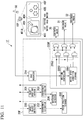
- the microphone 50 acquires voice from the human operating at the wet area such as the sink 400.
- the microphone 50 outputs the information indicating the acquired voice to the water spout control device 20F.
Landscapes
- Life Sciences & Earth Sciences (AREA)
- Health & Medical Sciences (AREA)
- Engineering & Computer Science (AREA)
- Hydrology & Water Resources (AREA)
- Public Health (AREA)
- Water Supply & Treatment (AREA)
- Physics & Mathematics (AREA)
- General Life Sciences & Earth Sciences (AREA)
- General Physics & Mathematics (AREA)
- Geophysics (AREA)
- Domestic Plumbing Installations (AREA)
- Geophysics And Detection Of Objects (AREA)
Abstract
Description
- The present disclosure relates to a water spout control device, a water spout control system, and a water spout control method.
- The present application claims priority on Japanese Patent Application No.
2018-067373, filed on March 30, 2018 - In recent years, along with the development of a behavior recognition technology for recognizing an intention of a human behavior from the human behavior itself, development of a system configured to automatically understand the intention of a human so as to properly control a faucet even if the human does not operate the faucet is expected.
- For example, a technology of providing a camera in a tip end portion of a faucet spout, determining a handwash action of the human according to an image captured by the camera, and prompting the human to proper handwash action in response to a situation is disclosed (see Patent Document 1).
- A technology of determining the degree of dirtiness of a cleaning object which is put out to be in front of a faucet spout port by the image captured by the camera, wherein the camera is provided in the faucet so as to be able to capture an image of the vicinity of the faucet spout port, and a technology of controlling a flow rate and a water pressure of the water to be discharged and a form of the water to be discharged, such as a straight water flow or a shower water flow for example are disclosed (see Patent Document 2).
-
- [Patent Document 1] Japanese Patent No.
5884554 - [Patent Document 2] Japanese Unexamined Patent Application, First Publication No.
2015-148107 - However, in a situation of utilizing the above described technologies, a camera, a sensor and the like have to be provided in the tip end portion of the faucet spout and the faucet. Accordingly, in a situation when the water is poured on the faucet spout, there is possibility that water droplets stick to the camera lens and the sensor window. In a situation of cleaning the cleaning object, there is possibility that dirt such as splash of cleaning solvent and the like sticks to the camera lens and the sensor window from the cleaning object to soil the camera lens and the sensor window. In a case of determining the handwash action and the like according to an unclear image captured by the camera whose lens are soiled, there is possibility that the determination result becomes incorrect. In a case that the sensor window is soiled, there is possibility to lead to a misdetection of the target object.
- In order to provide the camera and the sensor in the tip end portion of the faucet spout, it is necessary to make the camera and a sensor circuit integrated in the faucet including the faucet spout port. In this case, since it is necessary to secure a space for disposing the camera and the sensor circuit, a design of the faucet may be restricted.
- The present disclosure is made in consideration of such circumstances, and an object is to provide a water spout control device, a water spout control system, and a water spout control method so as to control the water discharging according to the detection result without making the camera and the sensor circuit to be integrated in the faucet.
- According to an embodiment of the present disclosure, a water spout control device has a target obj ect detector configured to detect a position of a target object as a detection target in a regional image according to an image information of the regional image, the regional image being generated by capturing an imaging target region including a faucet spout, a faucet spout port detector configured to detect a position of a faucet spout port of the faucet spout in the regional image, and a determiner configured to determine whether to discharge water according to the position of the target object detected by the target object detector and the position of the faucet spout port detected by the faucet spout port detector.
- In the water spout control device according to the embodiment describe above, the target object detector may detect the position of the target object in each of the regional images in a time series, and the water spout control device may further include a switcher configured to switch a water discharging state regarding the water to be discharged according to the position of the target object at time of being detected by the target object detector and the position of the target object at any time before the time when the target object is detected by the target object detector.
- In the water spout control device according to the embodiment described above, the switcher may be configured to switch the water discharging state according to a change of the positions of the target object detected by the target object detector in the time series.
- The water spout control device according to the embodiment described above, may further include a state detector configured to detect a state of the target object according to the regional image and the target object detected by the target object detector, and the switcher may be configured to switch the water discharging state according to the state of the target object detected by the state detector.
- The water spout control device according to the embodiment described above, may further include a characteristic extractor configured to extract characteristic of a human in the regional image according to the regional image, and the switcher may be configured to switch the water discharging state according to the characteristic of the human extracted by the characteristic extractor.
- The water spout control device according to the embodiment described above, may further include a behavior extractor configured to extract a behavior of a human in the regional image according to the regional image, and the switcher may be configured to switch the water discharging state according to the behavior of the human extracted by the behavior extractor.
- The water spout control device according to the embodiment described above, may further include an instruction detector configured to detect a content of an instruction according to an instruction information indicating the instruction to switch the water discharging state, and the switcher may be configured to switch the water discharging state according to the content of the instruction detected by the instruction detector.
- In the water spout control device according to the embodiment described above, the switcher may be configured to update a water discharging condition to switch the water discharging state according to the content of the instruction acquired from the instruction detector.
- In the water spout control device according to the embodiment described above, the water discharging state may be at least one of a type of the water to be discharged or a form of the water to be discharged.
- According to an embodiment of the present disclosure, a water spout control system has an imaging device configured to capture a regional image including a faucet spout and the water spout control device described above which is configured to acquire the image information of the regional image captured by the imaging device.
- In a water spout control method according to an embodiment of the present disclosure, a target object detector detects a position of a target object as a detection target in a regional image according to an image information of the regional image in which an imaging target region including a faucet spout, a faucet spout port detector detects a position of a faucet spout port of the faucet spout in the regional image, and a determiner determines whether to discharge water according to the position of the target object detected by the target object detector and the position of the faucet spout port detected by the faucet spout port detector.
- According to the water spout control device, the water spout control system, and the water spout control method according to the embodiments described above, there is possibility to control the water discharging according to the detection result without making the camera and the sensor circuit to be integrated in the faucet.
-
-
Fig. 1 is a block diagram showing a configuration example of a waterspout control system 1 according to a first embodiment. -
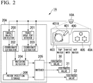
Fig. 2 is a block diagram showing a configuration example of a waterspout control system 1A according to a second embodiment. -
Fig. 3 is a flowchart showing an operation example of a waterspout control device 20A according to the second embodiment. -
Fig. 4 is a flowchart showing an operation example of the waterspout control device 20A according to the second embodiment. -
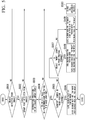
Fig. 5 . is a flowchart showing an operation example of the waterspout control device 20A according to the second embodiment. -
Fig. 6 is a block diagram showing a configuration example of a waterspout control system 1B according to a third embodiment. -
Fig. 7 is a view showing control performed by a waterspout control device 20B according to the third embodiment. -
Fig. 8 is a block diagram showing a configuration example of a water spout control system 1C according to a fourth embodiment. -
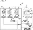
Fig. 9 is a block diagram showing a configuration example of a waterspout control system 1D according to a fifth embodiment. -
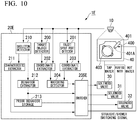
Fig. 10 is a block diagram showing a configuration example of a waterspout control system 1E according to a sixth embodiment. -
Fig. 11 is a block diagram showing a configuration example of a waterspout control system 1F according to a seventh embodiment. - Hereinafter, water spout control systems and water spout control devices according to each embodiment of the present disclosure will be described by referring to figures.
- At first, a first embodiment will be described.
-
Fig. 1 is a block diagram showing a configuration example of a waterspout control system 1 according to a first embodiment. The waterspout control system 1, for example, has animaging device 10 and a waterspout control device 20. The waterspout control device 20 is connected to asolenoid valve 30 configured to make afaucet spout 401 start or finish discharging water. In the waterspout control system 1, the waterspout control device 20 controls water discharging or stopping the water discharging by a control signal to open and close thesolenoid valve 30 of thefaucet spout 401 according to an image of animaging target region 40 captured by theimaging device 10. Here, the image of theimaging target region 40 captured by theimaging device 10 is an example of a "regional image". - The
imaging device 10, for example, is disposed at a place such as a kitchen and the like where water is utilized and configured to capture an image of theimaging target region 40. Theimaging target region 40 is a region including thefaucet spout 401, for example, a region such as a worktop and the like where water equipment such as asink 400 in which thefaucet spout 401 is disposed. Theimaging device 10, for example, captures an image of a broader region than that of thesink 400, i.e. a region including thesink 400 and astove 405. Theimaging device 10, for example, is disposed in the surrounding of thefaucet spout 401 such as a ceiling of the kitchen, an external lateral surface of a base plate of a wall cabinet, and the like. In a case when theimaging device 10 is disposed on the ceiling of the kitchen, a bulb type camera attachable to a luminaire wiring apparatus may be utilized. In this case, theimaging device 10 operates by power supplied from the luminaire wiring apparatus. In this case, theimaging device 10 is disposed in the upward direction of thefaucet spout 401. In this case, theimaging device 10, for example, is disposed so as to make a region at a lower side viewed from the upward direction of thefaucet spout 401 be the imaging region. In other words, theimaging device 10 captures an image of the region including thefaucet spout 401 from a position viewing down thefaucet spout 401. - The
imaging device 10 transmits an image information of the captured image to the waterspout control device 20. Theimaging device 10 transmits the image information of the captured image to the waterspout control device 20 via a wireless communication line such as a WiFi, for example. Theimaging device 10 may capture a still image or a motion image . Theimaging device 10 may capture a color image or a monochrome image. - The water
spout control device 20, for example, has atarget object detector 200, a faucetspout port detector 201, a coordinateextractor 202, a coordinateextractor 203 and amatching detector 204. The matchingdetector 204 is an example of a "determiner". - The
target object detector 200 detects whether the target object existing in an image according to the image of theimaging target region 40 which is captured by theimaging device 10. The target object refers to an object which may be a target of the water discharging, for example, adish 402, a pot 403 (seeFig. 2 ), a cup, a human hand, and the like. Hereinafter, the target object will be simply described as the object. - The
target object detector 200, for example, is configured to extract various objects captured in the image by performing an edge detection. Thetarget object detector 200, for example, performs the edge detection according to a luminance difference in the image data. Specifically, thetarget object detector 200 applies various rectangle frames, in other words, various cells in the image, and when the luminance difference of the external circumference of the frame compared to that inside the frame is small, thetarget object detector 200 determines that there is an object inside the frame and extracts the object from the image by extracting the frame. - The
target object detector 200 selects the target object from the objects extracted from the image. Thetarget object detector 200, for example, stores images of the target objects such as the dishes and the like that are captured in various imaging conditions, for example imaging angle, illumination and the like in advance. Thetarget object detector 200, for example, sets the same scale for the image of the target object stored in advance and the image of the object extracted from the image captured by theimaging device 10 and then compares the pixels in the two images. Thetarget object detector 200, for example, determines that the object extracted from the image is the target object in a case when a tendency of color distribution per each pixel matches with each other at a degree equal to or more than a predetermined threshold. Thetarget object detector 200 outputs a detection result to the coordinateextractor 202. - The faucet
spout port detector 201 detects whether thefaucet spout port 401A exists in the image according to the image of theimaging target region 40 captured by theimaging device 10. The faucetspout port detector 201, for example, detects that thefaucet spout port 401A exists in the image in a case when an end portion of thesink 400 in thefaucet spout 401 is captured in the image. The faucetspout port detector 201, for example, detects that thefaucet spout port 401A does not exist in the image in a case when the end portion of thesink 400 in thefaucet spout 401 is hidden by another object so as to not be captured in the image. The faucetspout port detector 201 outputs the detection result to the coordinateextractor 203. In the present embodiment, thefaucet spout port 401A is disposed at a downstream side of a flow path of thefaucet spout 401. - The coordinate
extractor 202 extracts positional coordinates indicating the position of the target object in the image according to the image captured by theimaging device 10 and the detection result output from thetarget object detector 200. The positional coordinate may be a coordinate indicating a gravity center of the target object, and the positional coordinates may be coordinate groups indicating the external circumference of the target object. The coordinateextractor 202 outputs the extracted positional coordinates of the target object in the image to thematching detector 204. - The coordinate
extractor 203 extracts positional coordinates indicating a position of thefaucet spout port 401A in the image according to the image captured by theimaging device 10 and the detection result output from the faucetspout port detector 201. The coordinateextractor 202 outputs the extracted positional coordinates of thefaucet spout port 401A in the image to thematching detector 204. - As shown above, an example of extracting the positional coordinates of the
faucet spout port 401A by the coordinateextractor 203 according to the image captured by theimaging device 10 is described, however, the present disclosure it not limited thereto. The coordinateextractor 203, for example, may detect the position of thefaucet spout port 401A according to a rotary angle of thefaucet spout 401 in a case when the position of thefaucet spout port 401A is movable by rotating thefaucet spout 401 with a length of thefaucet spout 401 in a longitudinal direction as a rotation radius. In this case, thefaucet spout 401, for example, may have a rotary angle measurement device such as a rotary encoder and the like for detecting the rotary angle of thefaucet spout 401 to be disposed at a side different from the side of thefaucet spout port 401A in thefaucet spout 401, that is, at a root portion of thefaucet spout 401. The rotary angle measurement device is configured to measure the rotary angle of thefaucet spout 401 and output the measurement result to the coordinateextractor 203. The coordinateextractor 203 extracts the positional coordinates of thefaucet spout port 401A according to the measurement result from the rotary angle measurement device, the coordinates of the root portion of thefaucet spout 401 and the length of thefaucet spout 401 in the longitudinal direction that are already known. - The coordinate
extractor 203 may be configured to acquire a control information for controlling a motor from a driver configured to drive the motor in a case when the rotation of thefaucet spout 401 is controlled by an operation of the motor. The coordinateextractor 203 calculates the rotary angle of thefaucet spout 401 according to the control information for controlling the motor and extract the positional coordinates of thefaucet spout port 401A according to the calculated rotary angle. - The matching
detector 204 detects whether the positional coordinates of the target object extracted from the coordinateextractor 202 and the positional coordinates of thefaucet spout port 401A extracted from the coordinateextractor 203 match with each other. The matchingdetector 204, for example, determines that both of the positional coordinates match with each other in a case when a distance between the positional coordinates of the target object and the positional coordinates of thefaucet spout port 401A is less than a predetermined threshold. The matchingdetector 204 determines that both of the positional coordinates match with each other in a case when the positional coordinates of thefaucet spout port 401A are included in a region in which the target object assumed according to the positional coordinates of the target object exists. - The matching
detector 204 determines to open thesolenoid valve 30 for tap water and outputs a control information indicating the determination to thesolenoid valve 30 in a case when it is determined that the positional coordinates of the target object and the positional coordinates of thefaucet spout port 401A match with each other. The matchingdetector 204 determines to close thesolenoid valve 30 and outputs the control information indicating the determination to thesolenoid valve 30 in a case when it is determined that the positional coordinates of the target object and the positional coordinates of thefaucet spout port 401A do not match with each other. At this time, the matchingdetector 204 may store and keep the open and close state of thesolenoid valve 30 in a storage which is not shown in the figure, and the matchingdetector 204 may perform the control process to output the control information to thesolenoid valve 30 in the case of changing the state of thesolenoid valve 30. Specifically, the matchingdetector 204 outputs the control information for opening thesolenoid valve 30 in the case of changing thesolenoid valve 30 from the closed state to the open state, and the matchingdetector 204 outputs the control information for closing thesolenoid valve 30 in the case of changing thesolenoid valve 30 from the open state to the closed state. - The general process of operations of the water
spout control device 20 will be described below. - At first, the water
spout control device 20 acquires an image information of the image ofimaging target region 40 that is captured by theimaging device 10. The waterspout control device 20 outputs the acquired image information to thetarget object detector 200 and the faucetspout port detector 201. - Next, the
target object detector 200 detects whether the target object is included in the image. Thetarget object detector 200 outputs the detection result to the coordinateextractor 202. The coordinateextractor 202 extracts the positional coordinates of the target object and output the extracted positional coordinates to thematching detector 204. - The faucet
spout port detector 201 detects whether thefaucet spout port 401A is included in the image. The faucetspout port detector 201 outputs the detection result to the coordinateextractor 203. The coordinateextractor 203 extracts the positional coordinates of thefaucet spout port 401A and outputs the extracted positional coordinates to thematching detector 204. - The matching
detector 204 controls the water discharging due to the control information for opening/closing thesolenoid valve 30 according to the positional coordinates extracted from each of the coordinateextractor 202 and the coordinateextractor 203. - As described above, the water
spout control device 20 according to the first embodiment has atarget object detector 200 and a coordinateextractor 202 which are configured to detect a position of a target object as a detection target in a regional image according to an image information of the regional image in which animaging target region 40 including afaucet spout 401, a faucetspout port detector 201 and a coordinateextractor 203 which are configured to detect a position of afaucet spout port 401A of thefaucet spout 401 in the regional image, and amatching detector 204 configured to determine whether to discharge water according to the position of the target object detected by thetarget object detector 200 and the position of thefaucet spout port 401A detected by the faucetspout port detector 201. Accordingly, the waterspout control device 20 according to the first embodiment determines whether the target object is put out to thefaucet spout port 401A according to the positions of thefaucet spout port 401A in thefaucet spout 401 and thedish 402 and the like as the target objects according to the regional image. When the target object is put out to thefaucet spout port 401A, the waterspout control device 20 recognizes the human actions of putting out the target object as an action of discharging the water to the target object and the waterspout control device 20 may start the water discharging. Accordingly, without integrating the camera and the sensor circuit in the faucet, the waterspout control device 20 recognizes human actions and automatically control the water discharging. - Next, a second embodiment will be described. A water
spout control system 1A according to the present embodiment is different from the first embodiment described above in that during the water discharging, a type of the water to be discharged is selected from either tap water, purified water, and hot water. The type of the water to be discharged is an example of a state corresponding to the water to be discharged, i.e. "a water discharging state". The type of the water to be discharged is not limited thereto, for example, functional water such as hot purified water, carbonated water, sterilized water, alkaline ionized water, and the like may be included. - Hereinafter, features different from the embodiment described above will be described, the configurations having the same or similar functions with respect to the embodiment described above will be designated as the same reference sign and the reductant description will be omitted.
-
Fig. 2 is a block diagram showing a configuration example of the waterspout control system 1A according to the second embodiment. The waterspout control system 1A has animaging device 10A and a waterspout control device 20A. The waterspout control device 20A is connected to each of thesolenoid valve 30 for making thefaucet spout 401 to discharge tap water, asolenoid valve 31 for making thefaucet spout 401 to discharge purified water, and asolenoid valve 32 for making thefaucet spout 401 to discharge hot water. - The
imaging device 10A is configured to capture images of animaging target region 40A at predetermined time intervals. Besides the water equipment such as thesink 400 and the like, theimaging device 10A captures images of a region as animaging target region 40A in which equipment that may be a movement source in a case when the target object moves to the vicinity of thefaucet spout port 401A. The equipment that may be the movement source refers to the equipment in which the target object exists before the target object is moved to thesink 400, and is an example of "a prior position". - The equipment that may be the movement source refers to, for example, the
stove 405, a dining table, a workbench for presenting dish after preparation and cooking of the food, a kitchen cabinet for accommodating dishes and cups, and a storage rack for accommodating the pots and the like. For example, after cooking using thepot 403 at thestove 405, in order to clean thepot 403 after the cooking, there is a case in which the human moves thepot 403 from thestove 405 to thesink 400. In this case, since the target object, i.e. thepot 403 is moved from thestove 405 to thesink 400, the equipment may be the movement source refers to thestove 405. - The coordinate
extractor 202 sequentially acquires the images captured by theimaging device 10A at predetermined time intervals. The coordinateextractor 202 detects the target object in each of the images in time series which are sequentially acquired from theimaging device 10A. In a case when the target object exists at the equipment as the movement source, i.e. thestove 405 for a predetermined period according to the images in time series, the coordinateextractor 202 makes aprior position storage 206 store an information by associating the target object and the equipment as the movement source. - Specifically, the coordinate
extractor 202 extracts the positional coordinates of the target object in the image captured by theimaging device 10A, and the coordinateextractor 202 determines whether the target object exists in the movement source equipment, i.e. thestove 405 for a predetermined period according to the extracted positional coordinates. In a case when the coordinateextractor 202 determines that the target object exists in the movement source equipment for the predetermined period, the coordinateextractor 202 makes theprior position storage 206 store the information generated by associating the target object with the positional coordinates. - The matching
detector 204 detects whether the positional coordinates of the target object which are extracted by the coordinateextractor 202 and the positional coordinates of thefaucet spout port 401A which are extracted by the coordinateextractor 203 match with each other, and the matchingdetector 204 outputs the detection result to theswitcher 205. - The
switcher 205 determines whether to perform the water discharging according to the detection result output by the matchingdetector 204. In the case of performing the water discharging, theswitcher 205 selects the type of the water to be discharged from either of tap water, purified water, and hot water according to the contents stored in theprior position storage 206. Theswitcher 205, for example, determines to open thesolenoid valve 30 for tap water in the case when it is determined that the positional coordinates of the target object and the positional coordinates of thefaucet spout port 401A match with each other. Theswitcher 205 selects the type of water to be discharged according to the movement source of the target object by referring to theprior position storage 206. - The
switcher 205, for example, in the case when thepot 403 as the target object is moved from thestove 405 to thesink 400, recognizes that the human attempts to clean thedirty pot 403 used for cooking from the actions of moving thepot 403 from thestove 405 to thesink 400 by the human. In this case, theswitcher 205 determines to open thesolenoid valve 32 for hot water and makes thefaucet spout 401 to perform the water discharging. Since it is assumed that oil stain adheres to thepot 403 used for cooking at thestove 405, it is more suitable to use hot water to clean the oil stain than using tap water. - The
switcher 205, for example, in the case when the cup as the target object is moved from the kitchen cabinet to thesink 400, recognizes that the human attempts to fetch the cup accommodated in the kitchen cabinet to fill the cup with drinking water according to the actions of moving the cup from the kitchen cabinet to thesink 400 by the human. In this case, theswitcher 205 determines to open thesolenoid valve 31 for purified water and makes thefaucet spout 401 perform the water discharging. - The
switcher 205, for example, in the case when the cup as the target object is moved from the dining table and the workbench to thesink 400, recognizes that the human attempts to fetch the cup that is used by the human at the dining table and the like to thesink 400 and clean the cup from the actions of moving the cup from the dining table and the like to thesink 400 by the human. In this case, theswitcher 205 determines to open thesolenoid valve 30 for tap water and makes thefaucet spout 401 perform the water discharging. It is assumed that relatively litter dirt compared with the oil stain adheres to the cup after the drinking water is drunk and it is considered to be enough to use tap water to clean the slight amount of dirt. - The
prior position storage 206 stores the information by associating the target object and the corresponding positional coordinates output by the coordinateextractor 202. -
Fig. 3 is a flow chart showing an operation example of the waterspout control device 20A according to the second embodiment. Hereinafter, the general flow of the operations of the waterspout control device 20A will be described by usingFig. 3 . In the description below, the target object will be described as "object" only. In the description below, theimaging target region 40A shows an example of a region where thesink 400 and thestove 405 are provided and a region where the kitchen cabinet, the workbench, and the storage rack for the pot and the like are not captured. - At first, the water
spout control device 20A acquires an image information of an image of theimaging target region 40A captured by theimaging device 10A (Step S100) . The waterspout control device 20A outputs the acquired image information to thetarget object detector 200 and the faucetspout port detector 201. - Next, the
target object detector 200 performs a detection process for an object to detect whether the target object is included in the image (Step S200) . Thetarget object detector 200 outputs the detection result to the coordinateextractor 202. - Subsequently, the coordinate
extractor 202 extracts the positional coordinates of the target object, and the coordinateextractor 202 performs the prior position storage process to make theprior position storage 206 store the coordinates as the movement source of the target obj ect according to the extracted coordinates (Step S300) . - Subsequently, the faucet
spout port detector 201 performs a detection process of thefaucet spout port 401A to detect whether thefaucet spout port 401A is included in the image (Step S400) . The faucetspout port detector 201 outputs the detection result to the coordinateextractor 203. The coordinateextractor 203 extracts the positional coordinates of thefaucet spout port 401A and outputs the extracted positional coordinates to thematching detector 204. - The matching
detector 204 and theswitcher 205 perform the switching process to switch the water discharging according to the detection result by thetarget object detector 200, the content of the prior position storage process by the coordinateextractor 202, and the detection result of thefaucet spout port 401A by the faucet spout port detector 201 (Step S500). -
Fig. 4 is a flow chart showing an operation example of the waterspout control device 20A according to the second embodiment. Hereinafter, a flow of the prior position storage process shown in the Step S300 will be described by usingFig. 4 . - The coordinate
extractor 202 uses a variable temp as a premise to perform the prior position storage process. The variable temp is a variable to accommodate a positional information of the object in the image. For example, an information indicating "sink" in a case when the object is in thesink 400, an information indicating "stove" in a case when the object is at thestove 405, an information indicating "other" in a case when the object is placed at a place rather than thesink 400 and thestove 405, and an information indicating "none" in a case when the object is not existed in the image are included in the variable temp. An initial value of the variable temp may be any other value besides "sink", "stove", "other", and "none" described above. Hereinafter, an example that the initial value of the variable temp is "none" will be shown. - The coordinate
extractor 202 uses a counter CT when performing the prior position storage process. The counter CT is a variable for measuring a period when the target object exists in a specified equipment, i.e. thesink 400, thestove 405, and the like. - At first, the coordinate
extractor 202 determines whether the target object is detected in the image captured by theimaging device 10A according to the detection result output from the target object detector 200 (Step S301). - Next, the coordinate
extractor 202 extracts the positional coordinates of the target object, that is, a position BP of the object in a case when the target object is detected from the image (Step S302). The coordinateextractor 202 determines whether the extracted position BP and the variable temp match with each other (Step S303) . The coordinateextractor 202, for example, determines that the position BP to be either of "sink", "stove", "other", and "none" according to the positional coordinates of the object, and the coordinateextractor 202 determines whether the determination result and the variable temp match with each other. - In a case when the position BP and the variable temp match with each other, the coordinate
extractor 202 refers to a counter value of the counter CT and determines whether the counter value of the counter CT has expired (Step S304). In a case when the counter value of the counter CT has expired, the coordinateextractor 202 makes theprior position storage 206 store the positon BP of the object (Step S305). On the other hand, in a case when the counter value of the counter CT has not expired, the coordinateextractor 202 applies an increment with respect to the counter CT (Step S308) . Then the waterspout control device 20A performs process shown in Step S400. - On the other hand, in the process shown in Step S303, in a case when the position BP and the variable temp do not match with each other, the coordinate
extractor 202 initiates the counter value of the counter CT to be zero (Step S306). Then the coordinateextractor 202 applies the value corresponding to the position BP, i.e. either of "sink", "stove", "other", and "none" to the variable temp (Step S307). - In the process shown in Step S301, in a case when the target object is not detected in the image, the coordinate
extractor 202 refers to the variable temp to determine whether the value "none" is included in the variable temp (Step S309). - In the case when the value "none" is included in the variable temp, the coordinate
extractor 202 refers to the counter value of the counter CT to determine whether the counter value of the counter CT has expired (Step S310) . In a case when the counter value of the counter CT has expired, the coordinateextractor 202 makes theprior position storage 206 store the value "none" as the position BP of the object (Step 311). On the other hand, in a case when the counter value of the counter CT has not expired, the coordinateextractor 202 applies an increment with respect to the counter CT (Step S314) . Then the waterspout control device 20A performs the process shown in Step S400. - In the process shown in Step S309, in a case when the value "none" is included in the variable temp, the coordinate
extractor 202 initiates the counter value of the counter CT to be zero (Step S312) . Then the coordinateextractor 202 applies the value "none" with respect to the variable temp (Step S313). -
Fig. 5 is a flow chart showing an operation example of the waterspout control device 20A according to the second embodiment. Hereinafter, a flow of the switching process shown in Step S500 will be described by usingFig. 5 . - At first, the
target object detector 200 determines whether the object is detected in the image (Step S501) . In a case when the object is detected in the image, the coordinateextractor 202 extracts the position BP of the object. The coordinateextractor 202 outputs the extracted position BP of the object to thematching detector 204. - Next, in the case when the obj ect is detected from the image, the faucet
spout port detector 201 determines whether thefaucet spout port 401A is detected from the image (Step S502). In a case when thefaucet spout port 401A is detected from the image, the coordinateextractor 203 extracts the positional coordinates of thefaucet spout port 401A, that is, a position TP (Step S503) . - The matching
detector 204 determines whether the position BP of the object and the position TP of thefaucet spout port 401A match with each other. Specifically, the matchingdetector 204 determines whether the positional coordinates of the position BP of the object are in a predetermined range from the positional coordinates of the position TP of thefaucet spout port 401A (StepS504). The matchingdetector 204 outputs the determination result to theswitcher 205. - The
switcher 205 determines the type of the water to be discharged from any of tap water, purified water, and hot water according to the determination result output from the matchingdetector 204 and the content stored in theprior position storage 206. - Specifically, the
switcher 205 refers to theprior position storage 206 to determine whether the value "stove" is stored as the prior position of the object, that is, the movement source (same in the description below) (Step S505) . In a case when the value "stove" is stored as the prior position of the object, theswitcher 205 outputs control signals for closing thesolenoid valve 31 of purified water and thesolenoid valve 30 of tap water and controls signals for opening thesolenoid valve 32 of hot water to each of thesolenoid valve 30, thesolenoid valve 31, and the solenoid valve 32 (Step S506). - In a case when the value "stove" is not stored as the prior position of the object in the process shown in Step S505, the
switcher 205 determines whether the value "none" is stored as the prior position of the object (Step S507). In a case when the value "none" is stored as the prior position of the object, theswitcher 205 outputs control signals for opening thesolenoid valve 31 of purified water and control signals for closing thesolenoid valve 30 of tap water and thesolenoid valve 32 of hot water to each of thesolenoid valve 30, thesolenoid valve 31, and the solenoid valve 32 (Step S508). The region where the kitchen cabinet, the workbench, the storage rack for the pot and the like are provided is not included in theimaging target region 40A such that in the case when the prior position is the value "none", the control process is performed on the assumption that the region for accommodating the target object, i.e. the storage rack for accommodating the pot when thepot 403 is regarded as the target object is the movement source. - In a case when the value "none" is not stored as the prior position of the object in the process shown in Step S507, that is, the value "sink" or the value "other" is stored as the prior position of the object, the
switcher 205 outputs control signals for closing thesolenoid valve 32 of hot water and thesolenoid valve 31 of purified water and control signals for opening thesolenoid valve 30 of tap water to each of thesolenoid valve 30, thesolenoid valve 31, and the solenoid valve 32 (Step S509) . In a case when the value of the prior position is the "sink" or "other", the control process if performed on the assumption that the object is used at an equipment except for the stove, i.e. the workbench and then moved to thesink 400 so as to clean the slight amount of dirt adhered on the target object. - In a case when the object is not detected from the image in the process shown in Step S501, in a case when the
faucet spout port 401A is not detected from the image in the process shown in Step S502, and in a case when the position BP of the object and the position TP of thefaucet spout port 401A do not match with each other in the process shown in Step S504, theswitcher 205 outputs control signals for closing all of thesolenoid valve 30, thesolenoid valve 31, and the solenoid valve 32 (Step S510). - According to the flow chart described above, the case when hot water is discharged when the value "stove" is stored in the
prior position storage 206 is described as an example, however, the present water spout control method is not limited thereto. - According to the present water spout control method, a method of controlling the type of the water to be discharged according to the content stored in the
prior position storage 206 may be voluntarily decided in response to a situation of the configuration of thesink 400, thestove 405 and the like, the configuration of thefaucet spout 401, and the demand of the human using thesink 400. - As described above, according to the water
spout control device 20A according to the second embodiment, thetarget object detector 200 detects the position of the target object in each of the regional images in a time series, and the waterspout control device 20A further includes aswitcher 205 configured to switch a water discharging state regarding the water to be discharged according to the position BP of the target object at time of being detected by thetarget object detector 200 and the position of the target object at any time before the time when the target object is detected by the target object detector, for example, the information indicating the position of the target object stored by theprior position storage 206. Accordingly, the waterspout control device 20A according to the second embodiment switches the type of the water to be discharged to hot water suitable for the cleaning of the oil stain, or purified water suitable for drinking and cooking according to whether the movement source of the target object is thestove 405 or the kitchen cabinet and the like in the case when the target object such as the pot and the like is moved to thesink 400. Thus, the waterspout control device 20A recognizes the actions of the human to automatically control the water discharging without integrating the camera and the sensor circuit inside the faucet. - Here, a tip end portion of the conventional faucet spout and a camera disposed at the faucet are considered as a comparison example. According to the comparison example, only a limited region under the
faucet spout port 401A is imaged. Accordingly, there is possibility to distinguish the case when the cup and the like are put out to the downward space of thefaucet spout port 401A, however, it is difficult to comprehend whether an intention of the human who puts the cup out is to drink the water using the cup or to clean the cup. - According to the water
spout control system 1A according to the present embodiment, theimaging device 10A does not only image the water equipment such as thesink 400 and the like, but also images the region including the equipment capable of being the movement source as theimaging target region 40A. Accordingly, there is possibility to detect the movement source where the target object exists before being moved to thesink 400, and there is possibility to realize the water spout control following the intention of the operating human according to the movement history of the target object. - Next, a third embodiment will be described. A water
spout control system 1B according to the present embodiment is different from the embodiments described above in a feature of selecting the type of the water to be discharged according to a plurality of different prior positions in a time series. - Hereinafter, features different from the embodiment described above will be described, the configurations having the same or similar functions with respect to the embodiment described above will be designated as the same reference sign and the reductant description will be omitted.
-
Fig. 6 is a block diagram showing a configuration example of the waterspout control system 1B according to the third embodiment. The waterspout control device 20B, for example, has aswitcher 205B, a firstprior position storage 206, a secondprior position storage 207, and a thirdprior position storage 208. - In a case when it is determined that the target obj ect exists in an equipment as the prior position for a predetermined period, the coordinate
extractor 202 makes the firstprior position storage 206 store an information by associating the target object and the positional coordinates. In this case, when the information indicating the prior position of the target object has already been stored in the firstprior position storage 206, the coordinateextractor 202 makes the secondprior position storage 207 store the information. Similarly, when the information indicating the prior position of the target object has already been stored in the secondprior position storage 207, the coordinateextractor 202 makes the thirdprior position storage 208 store the information. Inotherwords, the coordinateextractor 202 makes each of the firstprior position storage 206, the secondprior position storage 207, and the thirdprior position storage 208 store the movement history in the equipment where the target object exists for a certain period in a time series. - Each of the first
prior position storage 206, the secondprior position storage 207, and the thirdprior position storage 208 sequentially stores the information by associating the target object and the positional coordinates of the target object that are output from the coordinateextractor 202 in a time series. - The
switcher 205B determines whether to discharge the water or not according to the detection result output from the matchingdetector 204. In a case that it is determined to discharge the water, theswitcher 205B selects the type of the water to be discharged from either of tap water, purified water, and hot water according to the content stored in each of the firstprior position storage 206, the secondprior position storage 207, and the thirdprior position storage 208. Theswitcher 205B refers to each of the firstprior position storage 206, the secondprior position storage 207, and the thirdprior position storage 208 to select the type of the water to be discharged in response to the history of the prior position of the target object. -
Fig. 7 is a view showing control process performed by the waterspout control device 20B according to the third embodiment. Hereinafter, the process performed by theswitcher 205B to switch the type of the water to be discharged according to the content stored in each of the firstprior position storage 206, the secondprior position storage 207, and the thirdprior position storage 208 will be described usingFig. 7 . - In
Fig. 7 , various items such as a case number, aprior position 1, aprior position 2, aprior position 3, and content of a switching process are included. Regarding the case number, numbers are provided to uniquely identify cases of combinations of theprior position 1, theprior position 2, and theprior position 3. - Regarding the
prior position 1, theprior position 2, and theprior position 3, cases of the movement history of the target object are shown. In the example ofFig. 7 , the newest prior position in a time series is shown as theprior position 1, an older prior position is shown as theprior position 2, and the oldest prior position is shown as theprior position 3. - Regarding the content of the switching process, the content of switching the type of the water to be discharged by the
switcher 205B is shown with respect to each case number. - At first, as shown in the
case number 1 inFig. 7 , the process by theswitcher 205B in a case when the target object, i.e. thepot 403 and the cup is moved from the "sink 400" to the "stove 405", then moved from the "stove 405" to "none", that is, moved to the dining table, the workbench, and the kitchen cabinet and the like which is not imaged, and at last moved to the "sink 400" will be described. - In this case, according to the operations by the human to move the target object following the history shown in the
case number 1, theswitcher 205B recognizes that the human fills the target object with the water at thesink 400 according to the item ofprior position 3, then the human moves the target object with the water filled to thestove 405 for cooking and the like according to the item ofprior position 2, and then operations of dishing up the cooked food from the target object to the dishes at the dining table or the workbench according to the item ofprior position 1. - In a case when the empty target object, i.e. the
pot 403 and the cup is moved to thesink 400 after such movement history, theswitcher 205B recognizes that the human moving the empty target object attempts to clean the used empty target object. In the case, theswitcher 205B makes thefaucet 401 to discharge hot water. Since it is assumed that oil stain adheres to thepot 403 used for cooking at thestove 405, it is more suitable to use hot water to clean the oil stain than using tap water. - Next, as shown in the
case umber 2 inFig. 7 , the process by theswitcher 205B in a case when the target object is moved from "none", that is, the dining table, the workbench, and the kitchen cabinet to the "sink 400" will be described. - In this case, according to the operations by the human to move the target object following the history shown in the
case number 2, theswitcher 205B recognizes that the human does not move the target object to thestove 405 in advance according to the items fromprior position 1 toprior position 3 and the human moves the target object to thesink 400 such that theswitcher 205B recognizes that the human fetches the target object before being used from the storage rack or the kitchen cabinet and moves the target object to thesink 400. - In a case when the target object, i.e. the
pot 403 and the cup before being used is moved to thesink 400 after such movement history, theswitcher 205B recognizes that the human attempts to fill the target object with the water at thesink 400 for usage. In this case, theswitcher 205 makes thefaucet spout 401 to discharge purified water. It is because purified water is more suitable for cooking and drinking compared with tap water. - Next, as shown in the
case umber 3 inFig. 7 , the process by theswitcher 205B in a case when the target object is moved from "none", that is, the dining table, the workbench, and the kitchen cabinet to the "sink 400", then becomes "none" again, and then moved to the "sink 400" will be described. - In this case, according to the operations by the human to move the target object following the history shown in the
case number 3, theswitcher 205B recognizes that the target object, i.e. thepot 403 and the cup is fetched from the storage rack and the kitchen cabinet and used at the time when the human firstly moves the target object to thesink 400 according to the items of theprior position 3 and theprior position 2. Theswitcher 205B recognizes that the target object such as thepot 403 and the cup filled with the water is used at the dining table or used for cooking at the workbench at the time when the human next moves the target object to "none", that is, the dining table and the workbench that are not captured in the image according to the item of theprior position 1. - In a case when the target object, i.e. the
pot 403 and the cup used at the dining table and the workbench is moved to thesink 400 after such movement history, theswitcher 205B recognizes that the human attempts to place the used target object in thesink 400 for cleaning. In this case, theswitcher 205B makes thefaucet spout 401 to discharge tap water. Compared with the case when the oil stain adheres to thepot 403 that is used at thestove 405, it is assumed that only slight amount of dirt adheres to the target object which is drunk or used at the place such as the dining table or the workbench different from thestove 405 such that tap water rather than hot water is suitable for cleaning the slight amount of dirt. - Accordingly, a situation of wastefully using hot water and purified water to clean the slight amount of dirt is avoided, and there is possibility to avoid excessive usage of hot water and purified water so as to avoid useless energy consumption.
- As described above, according to the water
spout control device 20B according to the third embodiment, theswitcher 205B switches the water discharging state according to a change of the positions of the target object, for example the content stored in the firstprior position storage 206, the secondprior position storage 207, and the thirdprior position storage 208, detected by thetarget object detector 200 in the time series . Accordingly, in the case of moving the target object such as the pot and the like to thesink 400, there is possibility for the waterspout control device 20B according to the third embodiment to switch the type of the water to be discharged to hot water suitable for cleaning the oil stain or purified water suitable for drinking and cooking according to the movement history of the target obj ect. Thus, the waterspout control device 20B recognizes the operations of the human to automatically control the water discharging without integrating the camera and the sensor circuit inside the faucet. - Next, a fourth embodiment will be described. A water spout control system 1C according to the present embodiment is different from the embodiments described above in that the water spout control system 1C selects a form of water to be discharged from either of a straight water flow or a shower water flow while selecting a type of the water to be discharged according to a state of the target object. The form of the water to be discharged is an example of the "water discharging state".
- Hereinafter, features different from the embodiment described above will be described, the configurations having the same or similar functions with respect to the embodiment described above will be designated as the same reference sign and the reductant description will be omitted.
-
Fig. 8 is a block diagram showing a configuration example of the water spout control system 1C according to the fourth embodiment. A water spout control device 20C, for example, has aswitcher 205C and astate detector 209. The water spout control device 20C is connected with a switching mechanism configured to switch the form of the water discharging of thefaucet spout 401 that is not shown in figures, thesolenoid valve 30 for discharging tap water, thesolenoid valve 31 for discharging purified water, and thesolenoid valve 32 for discharging hot water. - The
state detector 209 detects a state of the target object when the target object exists in the image according to the image of theimaging target region 40 captured by theimaging device 10 and the detection result by thetarget object detector 200. The state of the target object refers to a dirty state of the target object, for example, a state of the target object without any dirt before being used, a dirty state of the target object after being used, and a state indicating a dirty degree when the target object is in the dirty state. - For example, in a case when the detection result by the
target object detector 200 indicates that the target object exists in the image, thestate detector 209 extracts a region of the target object from the image. - For example, the
state detector 209 stores a plurality of images in advance, wherein the plurality of images of the target object such as the dishes and the like are captured in various dirty states from a slightly dirty state to a heavily dirty state such as the oil stain and the like. Thestate detector 209 sets the same scale for the images of the target object in various dirty states and stored in advance and the image of the target object extracted from the image captured by theimaging device 10, and thestate detector 209 compares pixels in the two images. For example, in a case when a tendency of color distribution per each pixel matches with each other at a degree equal to or more than a predetermined threshold, thestate detector 209 determines that the dirt on the target object in the two images are at the same degree. Thestate detector 209 outputs the detection result to theswitcher 205C. - The
switcher 205C determines whether to discharge the water according to the detection result output from the matchingdetector 204. In a case when it is determined to discharge the water, theswitcher 205C selects the type of the water to be discharged from either of tap water, purified water, and hot water, and theswitcher 205C selects the form of the water to be discharged from the straight water flow or the shower water flow, for example, according to the dirty degree of the target object detected by thestate detector 209. - For example, in a case when the detection target object is the
pot 403, and it is determined that no dirt adheres to the detection target object by thestate detector 209, theswitcher 205C performs the water discharging by selecting purified water as the type of the water to be discharged and the straight water flow as the form of the water to be discharged. It is because that in a case of filing the pot for cooking with the water, in other words, storing the water in the pot, it is not necessary to perform the shower water flow and the straight water flow is suitable. - For example, in a case when the detection target object is the
pot 403, and it is determined that heavy dirt adheres to the detection target object by thestate detector 209, theswitcher 205C performs the water discharging by selecting hot water as the type of the water to be discharged and the shower water flow as the form of the water to be discharged. It is because that hot water is suitable for cleaning the heavy dirt adhering to thepot 403, and the shower water flow capable of discharging the water by a high water pressure in a wide range is suitable compared with the straight water flow. - For example, in a case when the detection target object is the cup, and it is determined that litter dirt adheres to the detection target object by the
state detector 209, theswitcher 205C performs the water discharging by selecting tap water as the type of the water to be discharged and the shower water flow as the form of the water to be discharged. It is because that tap water is suitable for cleaning the litter dirt adhering to the cup, and the shower water flow capable of discharging the water by a high water pressure in a wide range is suitable. - As described above, the case in which the
state detector 209 determines the dirty state of the target object according to the region of the dirt and the color is described as an example, however, the present disclosure is not limited thereto. Thestate detector 209 may determine the dirty state of the target object according to an orientation of the target object when the target object is put out to thefaucet spout port 401A, in other words, how the human holds the target object, or the human places the target object in which orientation. - For example, in a case when the detection target object is a cup and the cup is held or placed under the
faucet spout port 401A with a lip toward the upward direction, that is, toward the vertically upward direction, thestate detector 209 determines that there is no dirt adhering to the detection target object and the cup is put out for storing the drinking water. In this case, theswitcher 205C discharges purified water to the detection target object, i.e. the cup in the form of the straight water flow. - In a case when the detection target object is a cup and the cup is held or placed under the
faucet spout port 401A with the lip toward a different direction from the upward direction, for example, the cup is held or placed with the lip toward a horizontal direction, i.e. the left/right direction, thestate detector 209 determines that there is dirt adhering to the detection target object and the cup is put out for cleaning. In this case, theswitcher 205C discharges tap water to the detection target object, i.e. the cup in the form of the shower water flow. - As described above, the water spout control device 20C according to the fourth embodiment further has the
state detector 209 configured to determine the state of the target object according to the image captured by theimaging device 10 and the target object detected by thetarget object detector 200. Theswitcher 205C switches the water discharging state according to the state of the target object detected by thestate detector 209. Accordingly, in the case when the target object such as the pot and the like is moved to thesink 400, the water spout control device 20C according to the fourth embodiment switches the type of the water to be discharged and the form of the water to be discharged according to the dirty state of the target obj ect. Thus, the water spout control device 20C recognizes the operations of the human to automatically control the water discharging without integrating the camera and the sensor circuit inside the faucet. - Next, a fifth embodiment will be described. A water
spout control system 1D according to the present embodiment is different from the embodiments described above in that the waterspout control system 1D selects the type of the water to be discharged, the form of the water to be discharged, a temperature and a water pressure of the water to be discharged, and a flow rate according to characteristic of actions of a human being captured in the image. The temperature and the water pressure of the water to be discharged, and the flow rate are examples of the "water discharging state". - Hereinafter, features different from the embodiment described above will be described, the configurations having the same or similar functions with respect to the embodiment described above will be designated as the same reference sign and the reductant description will be omitted.
-
Fig. 9 is a block diagram showing a configuration example of the waterspout control system 1D according to the fifth embodiment. For example, a waterspout control device 20D has askeleton detector 210, acharacteristic extractor 211, and aswitcher 205D. - The
skeleton detector 210 detects the actions of the human being captured in the image according to the image captured by theimaging device 10. For example, theskeleton detector 210 acquires an information corresponding to the actions of the human by using a camera, i.e. an infrared camera and a sensor, i.e. a motion sensor. Theskeleton detector 210 extracts joints of the human according to the information corresponding to the actions of the human that is acquired by using the infrared camera and the like, and theskeleton detector 210 detects the skeleton of the human by connecting the extracted joints according to the skeleton structure of the human. Theskeleton detector 210 outputs an information corresponding to the actions and the skeleton of the detected human to thecharacteristic extractor 211. - The
characteristic extractor 211 extracts the characteristic of the actions of the human according to the information corresponding to the actions and the skeleton of the human detected by theskeleton detector 210. For example, thecharacteristic extractor 211 assumes a body height and a shoulder length according to the information corresponding to the skeleton and extracts the characteristic such as whether the human captured in the image is an adult or a child, and whether the human is a man or a woman if the human is an adult. - The
characteristic extractor 211 extracts the characteristic of the actions of the human according to the information corresponding to the actions of the human detected by theskeleton detector 210. The characteristic of the actions of the human is characteristic of the way to use his/her own body for each human such as whether there is a tendency of pulling the right shoulder than the left shoulder, whether there is a tendency of lifting the right shoulder than the left shoulder, and whether the human is right-handed or left-handed. Thecharacteristic extractor 211 output an information indicating the extracted characteristic to theswitcher 205D. - The
switcher 205D determines whether to perform the water discharging according to the detection result output from the matchingdetector 204, and in a case of performing the water discharging, theswitcher 205D selects the type of the water to be discharged, the form of the water to be discharged, the water pressure, and the flow rate according to the characteristic extracted by thecharacteristic extractor 211. - For example, the
switcher 205D adjusts the water pressure of the water to be discharged so as to avoid the water pressure from being too strong in a case when the human operating at thesink 400, that is, an example of the human captured in the image is assumed to be a child or an elderly human by thecharacteristic extractor 211. For example, theswitcher 205D adjusts the temperature of hot water to be discharged so as to avoid the temperature from being too high in a case when the human operating at thesink 400 is assumed to be a child or an elderly human by thecharacteristic extractor 211. In this case, thecharacteristic extractor 211 assumes that the human captured in the image is an elderly human in a case where a size of the skeleton of the human detected by theskeleton detector 210 is at the same size as a skeleton of an adult, and the change of the actions of the human detected by theskeleton detector 210 is at a speed lower than a predetermined threshold. - The
switcher 205D may control the water discharging to be in the straight water flow form with a higher flow rate than usual in a case when the human operating at thesink 400 is assumed to be an adult man, and theswitcher 205D may control the water discharging to be in the shower water flow form with a lower flow rate and more soften than usual in a case when the human operating at thesink 400 is assumed to be an adult woman. - As described above, the water
spout control device 20D according to the fifth embodiment further has acharacteristic extractor 211 configured to extract the characteristic of the human in the regional image according to the regional image captured by theimaging device 10. Theswitcher 205D switches the water discharging state according to the characteristic of the human in the regional image extracted by thecharacteristic extractor 211. Accordingly, the waterspout control device 20D according to the fifth embodiment switches the characteristic of the human who moves the target object such as the pot and the like to thesink 400 and operates at thesink 400, and the waterspout control device 20D switches the type of the water to be discharged and the form of the water discharging in response to the characteristic of the human. Thus, the waterspout control device 20D recognizes the operations of the human to automatically control the water discharging without integrating the camera and the sensor circuit inside the faucet. - As described above, the case when the
characteristic extractor 211 extracts the characteristic of the human according to the skeleton detected by theskeleton detector 210 is described as an example, however, the present disclosure is not limited thereto. For example, thecharacteristic extractor 211 may extract the characteristic of the human by performing a face authentication and a motion detection in the image captured by theimaging device 10. - Next, a sixth embodiment will be described. A water
spout control system 1E according to the present embodiment is different from the embodiments described above in that the water spout control system the waterspout control system 1E selects the type of the water to be discharged, the form of the water to be discharged, the water pressure of the water to be discharged, and the flow rate according to prior actions of a human being captured in the image. Hereinafter, features different from the embodiment described above will be described, the configurations having the same or similar functions with respect to the embodiment described above will be designated as the same reference sign and the reductant description will be omitted. -
Fig. 10 is a block diagram showing a configuration example of the waterspout control system 1E according to the sixth embodiment. The waterspout control device 20E, for example, has abehavior extractor 212, aprior behavior storage 213, and aswitcher 205E. - The
skeleton detector 210 outputs an information corresponding to the actions and skeleton of the detected human to thecharacteristic extractor 211 and outputs to thebehavior extractor 212 at the same time. - The
behavior extractor 212 extracts the behavior of the human according to the information corresponding to the detected actions of the human by theskeleton detector 210. The actions of the human refer to a movement source position of the human operating at the wet area such as thesink 400 and the like when the human moves to thesink 400. For example, the actions of the human refer to a movement history such as whether the human exists at thestove 405 or at the workbench before the human starts to clean at thesink 400. Thebehavior extractor 212 makes theprior behavior storage 213 to store an information by associating the human and positional coordinates when thebehavior extractor 212 determines that the human exists at the equipment of the movement source such as thestove 405 for a predetermined period. - The
prior behavior storage 213 stores the information by associating the human and the positional coordinates output by thebehavior extractor 212. - The
switcher 205E determines whether to perform the water discharging according to the detection result output from the matchingdetector 204. In a case of performing the water discharging, theswitcher 205D selects the type of the water to be discharged, the form of the water to be discharged, the water pressure, and the flow rate according to the content stored in theprior behavior storage 213. Theswitcher 205E refers to theprior behavior storage 213 to select the type of the water to be discharged and the like corresponding to the movement source of the human. - For example, in a case when the target object is the
pot 403, and the human operating at thesink 400 exists before thestove 405 before moving to thesink 400, theswitcher 205E recognizes that the human performs cooking at thestove 405 and then attempts to clean the usedpot 403 at thesink 400, and theswitcher 205E controls to discharge hot water in the form of shower water flow. In this case, for example, when the operating human is an adult man, theswitcher 205E controls to increase the flow rate, and when the operating human is an adult woman, theswitcher 205E controls to decrease the flow rate so as to control the flow rate to be suitable for the operating human. - For example, in a case when the target object is the cup and the human operating at the
sink 400 exists before the kitchen cabinet before moving to thesink 400, theswitcher 205E recognizes that the human attempts to drink water using the cup fetched from the kitchen cabinet, and theswitcher 205E controls to discharge purified water in the form of straight water flow. In this case, for example, theswitcher 205E controls to decrease the flow rate of the water when the operating human is a child so as to control the water to slowly fill the cup. - The water
spout control device 20E according to the sixth embodiment described above, further has thebehavior extractor 212 configured to extract the movement source of the human in the image according to the image captured by theimaging device 10. Theswitcher 205E is configured to switch the water discharging state according to the movement source of the human operating at thesink 400 extracted by thebehavior extractor 212. Accordingly, the waterspout control device 20E according to the sixth embodiment switches the type of the water to be discharged and the form of the water discharging in response to the prior position of the human who moves the target object such as thepot 403 and the like to thesink 400 and operates at thesink 400. Thus, the waterspout control device 20E controls the water discharging in response to the movement history of the human without integrating the camera and the sensor circuit inside the faucet. - As described above, the case when the
behavior extractor 212 extracts the behavior of the human according to the skeleton detected by theskeleton detector 210 is described as an example, however, the present disclosure is not limited thereto. For example, thebehavior extractor 212 may extract the behavior of the human by performing a face authentication and a motion detection in the image captured by theimaging device 10. - Next, a seventh embodiment will be described. A water
spout control system 1F according to the present embodiment is different from the embodiments described above in that the waterspout control system 1F selects the type of the water to be discharged, the form of the water to be discharged, the water pressure of the water to be discharged, and the flow rate according to an intention of the operating human. - According to the present embodiment, in a case when the human operating at the wet area such as the
sink 400 and the like considers the water discharging state controlled by the waterspout control system 1F not to be an intended state of the human, the operating human instructs to switch the water discharging. A voice instruction refers the instruction for switching the water discharging state selected by the water dischargingcontrol system 1F. For example, in a case when the human puts thepot 403 to thefaucet spout port 401A and purified water is discharged from thefaucet spout port 401A, if the human intends to fill thepot 403 with hot water, the human instructs to switch the water to be discharged to hot water by voice. - For example, in a case when the
pot 403 without any dirt is put out under thefaucet spout 401 and the waterspout control system 1F controls to discharge purified water, if the human intends to cook using purified water, the human does not instruct to switch the water discharging. On the other hand, in case when the waterspout control system 1F instructs to discharge purified water, however the human intends to boil hot water quickly by filling thepot 403 with hot water and then moving thepot 403 to thestove 405, the human instructs to switch the water discharging to discharge hot water. According to the present embodiment, control process of switching the water discharging following the intention of each operating human is performed according to the instructions by the voice of the operating human. - Hereinafter, features different from the embodiment described above will be described, the configurations having the same or similar functions with respect to the embodiment described above will be designated as the same reference sign and the reductant description will be omitted.
-
Fig. 11 is a block diagram showing a configuration example of the waterspout control system 1F according to the seventh embodiment. The waterspout control system 1F, for example, has animaging device 10F, a waterspout control device 20F, and amicrophone 50. A voice information acquired by themicrophone 50 is an example of the "instruction information". - The
microphone 50 acquires voice from the human operating at the wet area such as thesink 400. Themicrophone 50 outputs the information indicating the acquired voice to the waterspout control device 20F. - The water
spout control device 20F, for example, has avoice recognizer 214 and aswitcher 205F. Thevoice recognizer 214 is an example of "instruction detector". - The
voice recognizer 214 recognizes content of the voice from the human operating at the wet area such as thesink 400 according to the information indicating the voice acquired from themicrophone 50. Thevoice recognizer 214 recognizes whether the operating human is instructing to switch the water discharging state with respect to the process performed by the waterspout control system 1F according to the information indicating the voice. In a case when the human is instructing to switch the water discharging state, thevoice recognizer 214 recognizes which water discharging matches the intention of the human. Thevoice recognizer 214 outputs an information indicating the content of the instruction to theswitcher 205F when the human instructs to switch the water discharging state. - The
switcher 205F has awriting controller 2050, a waterspout condition storage 2051, and acondition updater 2052. - The
writing controller 2050 makes the waterspout condition storage 2051 to store an instruction information according to the content of the information for switching the water discharging recognized by thevoice recognizer 214. For example, in a case when the instruction information for switching the water discharging by thevoice recognizer 214 is recognized, thewriting controller 2050 makes the waterspout condition storage 2051 to store an information indicating which water discharging to perform in response to the prior position stored by theprior position storage 206. - The water
spout condition storage 2051 stores an information indicating which water discharging to perform by the human who instructs to switch the water discharging controlled by thewriting controller 2050. For example, in a case when thepot 403 is moved from the state outside the image to thesink 400 and then put out to thefaucet spout port 401A and the like such that purified water should be discharged following an ordinary condition according to the detection result of the matchingdetector 204 and theprior position storage 206, if there is an instruction for switching to discharge hot water, the waterspout condition storage 2051 stores an information indicating to fill thepot 403 with hot water even if the condition is the same. - The
condition updater 2052 controls the water discharging state according to each of the detection result of the matchingdetector 204, the content stored in theprior position storage 206, and the content stored in the waterspout condition storage 2051. For example, even if ordinarily purified water should be discharged in a case when thepot 403 existed in the storage rack is put out to thefaucet spout port 401A and the like, if the information indicating that the operating human captured in the image instructs to discharge hot water is stored in the waterspout condition storage 2051, thecondition updater 2052 instructs to discharge hot water. In other words, in a case of discharging the water according to the position of the detected target object, thecondition updater 2052 individually changes the water discharging condition so as to follow the intention of the operating human and apply customization in response to the desired water discharging state by the operating human. That is, thecondition updater 2052 updates the water discharging condition for switching the water discharging state in response to the intention of the operating human. - As described above, the water
spout control device 20F according to the seventh embodiment further has thevoice recognizer 214 configured to detect the content of the instruction, i.e. the content of an oral instruction according to the instruction information for instructing the water discharging state, i.e. the voice information of the voice acquired by themicrophone 50. Theswitcher 205F switches the water discharging state according to the recognition result of thevoice recognizer 214. Accordingly, the waterspout control device 20F according to the seventh embodiment switches the type of the water to be discharged and the form of the water discharging in response to the content of the instruction by the voice of the human operating at thesink 400. Thus, the waterspout control device 20F controls the water discharging in response to the intention shown by the human without integrating the camera and the sensor circuit inside the faucet. - In the water
spout control device 20F according to the seventh embodiment, theswitcher 205F updates the water discharging condition for switching the water discharging state according to the recognition result of thevoice recognizer 214. Accordingly, the waterspout control device 20F according to the seventh embodiment controls the water discharging following the water discharging state desired by the human using thesink 400. - As described above, the example in which the water
spout control device 20F controls the water discharging state according to the voice recognized by thevoice recognizer 214 is described, however, the present disclosure is not limited thereto. For example, the waterspout control device 20F may control the water discharging state according to a specified body gesture and a hand gesture of the human. - In this case, for example, the
water control device 20F has a motion detector which is not shown in figures and is configured to detect the instruction for switching the water discharging state performed by motions of the human such as the specified body gesture and the hand gesture according to the image captured by theimaging device 10F. The motion detector outputs the information indicating the instruction for switching the detected water discharging state to theswitcher 205F. The image information of the image captured by theimaging device 10F is an example of the "instruction information". The motion detector is an example of the "instruction detector". - The specified body gesture and the hand gesture of the human includes the operations of the human to directly operate the faucet. The operation to operate the faucet includes operations such as turning the faucet or operating the handle to water discharging, i.e. single lever. Accordingly, in a case that the water discharging is directly operated by moving a manual valve of a conventional single lever, there is possibility to detect content of the operation, and then to determine that it is the intention of the human operating at the wet area such as the
sink 400 to update the water discharging condition. - On the other hand, in a case when the human performs the operation of the conventional water discharging, the water discharging state may be controlled in response to the operation. Accordingly, the human operating the single lever and the like can naturally control the water discharging state without feeling unnatural.
- The whole or part of the process performed by the water
spout control devices - Although preferred embodiments of the present invention have been described above, the present invention is not limited to the embodiments and modifications thereof. Additions, omissions, substitutions and other changes in the structure are possible without departing from the spirit of the present invention. The present invention is not limited by the foregoing description and is limited only by the scope of the appended claims.
- According to the embodiments descripted above, a water spout control device, a water spout control system, and a water spout control method can be provided to control water discharging in response to a detection result without integrating a camera and a sensor circuit inside a faucet.
-
- 1
- water spout control system
- 10
- imaging device
- 20
- water spout control device
- 30
- solenoid valve
- 40
- imaging target region
- 400
- sink
- 401
- faucet spout
- 402, 403
- detection target object
- 405
- stove
- 50
- microphone
Claims (11)
- A water spout control device, comprising:a target object detector configured to detect a position of a target object as a detection target in a regional image according to an image information of the regional image, the regional image being generated by capturing an imaging target region including a faucet spout;a faucet spout port detector configured to detect a position of a faucet spout port of the faucet spout in the regional image; anda determiner configured to determine whether to discharge water according to the position of the target object detected by the target object detector and the position of the faucet spout port detected by the faucet spout port detector.
- The water spout control device according to claim 1,wherein the target object detector is configured to detect the position of the target object in each of the regional images in a time series, andthe water spout control device further includes a switcher configured to switch a water discharging state regarding the water to be discharged according to the position of the target object at time when the target object is detected by the target object detector and the position of the target object at any time before the time when the target object is detected.
- The water spout control device according to claim 2, wherein the switcher is configured to switch the water discharging state according to a change of the positions of the target object detected by the target object detector in the time series.
- The water spout control device according claim 2 or claim 3, further comprising a state detector configured to detect a state of the target object according to the regional image and the target object detected by the target object detector,
wherein the switcher is configured to switch the water discharging state according to the state of the target object detected by the state detector. - The water spout control device according to any one of claim 2 to claim 4, further comprising a characteristic extractor configured to extract characteristic of a human in the regional image according to the regional image,
wherein the switcher is configured to switch the water discharging state according to the characteristic of the human extracted by the characteristic extractor. - The water spout control device according to any one of claim 2 to claim 5, further comprising a behavior extractor configured to extract a behavior of a human in the regional image according to the regional image,
wherein the switcher is configured to switch the water discharging state according to the behavior of the human extracted by the behavior extractor. - The water spout control device according to any one of claim 2 to claim 6, further comprising an instruction detector configured to detect a content of an instruction according to an instruction information indicating the instruction to switch the water discharging state,
wherein the switcher is configured to switch the water discharging state according to the content of the instruction detected by the instruction detector. - The water spout control device according to any one of claim 2 to claim 6, further comprising an instruction detector configured to detect content of an instruction according to an instruction information indicating the instruction to switch the water discharging state,
wherein the switcher is configured to update the water discharging condition to switch the water discharging state according to the content of the instruction acquired from the instruction detector. - The water spout control device according to any one of claim 2 to claim 8, wherein the water discharging state is at least one of a type of the water to be discharged or a form of the water to be discharged.
- A water spout control system, comprising:an imaging device configured to capture a regional image including a faucet spout, andthe water spout control device according to any one of claim 2 to claim 9 which is configured to acquire the image information of the regional image captured by the imaging device.
- A water spout control method, comprising:detecting a position of a target obj ect as a detection target in a regional image according to an image information of the regional image in which an imaging target region including a faucet spout, by a target object detector;detecting a position of a faucet spout port of the faucet spout in the regional image, by a faucet spout port detector; anddetermining whether to discharge water according to the position of the target object detected by the target object detector and the position of the faucet spout port detected by the faucet spout port detector, by a determiner.
Applications Claiming Priority (2)
| Application Number | Priority Date | Filing Date | Title |
|---|---|---|---|
| JP2018067373A JP7185376B2 (en) | 2018-03-30 | 2018-03-30 | Water discharge control device, water discharge control system, and water discharge control method |
| PCT/JP2018/045651 WO2019187376A1 (en) | 2018-03-30 | 2018-12-12 | Water discharge control device, water discharge control system, and water discharge control method |
Publications (3)
| Publication Number | Publication Date |
|---|---|
| EP3779076A1 true EP3779076A1 (en) | 2021-02-17 |
| EP3779076A4 EP3779076A4 (en) | 2021-05-26 |
| EP3779076B1 EP3779076B1 (en) | 2025-01-22 |
Family
ID=68061155
Family Applications (1)
| Application Number | Title | Priority Date | Filing Date |
|---|---|---|---|
| EP18911936.5A Active EP3779076B1 (en) | 2018-03-30 | 2018-12-12 | Water spout control device, water spout control system, and water spout control method |
Country Status (5)
| Country | Link |
|---|---|
| US (1) | US11512457B2 (en) |
| EP (1) | EP3779076B1 (en) |
| JP (1) | JP7185376B2 (en) |
| CN (1) | CN111971439B (en) |
| WO (1) | WO2019187376A1 (en) |
Families Citing this family (5)
| Publication number | Priority date | Publication date | Assignee | Title |
|---|---|---|---|---|
| CN111503345B (en) * | 2019-01-31 | 2023-06-13 | 厦门优胜卫厨科技有限公司 | A water outlet device and control method |
| GB202016082D0 (en) * | 2020-10-09 | 2020-11-25 | Fresh Hands Ltd | Hand sanitiser apparatus |
| US12325987B2 (en) * | 2021-04-07 | 2025-06-10 | Assa Abloy Americas Residential Inc. | Electronic faucet with auto focus |
| CN114792399B (en) * | 2022-06-23 | 2023-01-06 | 深圳市海清视讯科技有限公司 | Plant monitoring method, device and equipment |
| JP2024034398A (en) * | 2022-08-31 | 2024-03-13 | Toto株式会社 | Water discharge control system |
Family Cites Families (19)
| Publication number | Priority date | Publication date | Assignee | Title |
|---|---|---|---|---|
| US3670167A (en) * | 1970-05-14 | 1972-06-13 | American Standard Inc | Proximity switching equipment |
| US4762273A (en) * | 1986-03-07 | 1988-08-09 | Stephen O. Gregory | Electronic faucet with spout position sensing means |
| JP2658459B2 (en) * | 1989-12-26 | 1997-09-30 | 松下電器産業株式会社 | Shower equipment |
| JP2823377B2 (en) * | 1991-03-29 | 1998-11-11 | 三洋電機株式会社 | Shower device |
| JPH1136396A (en) * | 1997-07-16 | 1999-02-09 | Mitsubishi Electric Corp | Automatic faucet |
| US20060231782A1 (en) * | 2005-04-14 | 2006-10-19 | Masco Corporation | CCD camera element used as actuation detector for electric plumbing products |
| JP5707891B2 (en) * | 2010-11-17 | 2015-04-30 | 住友電気工業株式会社 | Water supply control device and water supply system |
| JP2013017631A (en) * | 2011-07-11 | 2013-01-31 | Sumitomo Electric Ind Ltd | Hand washing monitor and method for monitoring hand washing |
| JP5884554B2 (en) | 2012-03-01 | 2016-03-15 | 住友電気工業株式会社 | Hand-washing monitor, hand-washing monitoring method and hand-washing monitor program |
| JP6199612B2 (en) * | 2013-05-31 | 2017-09-20 | 株式会社Lixil | Human body detection sensor and automatic faucet |
| JP6169935B2 (en) * | 2013-09-30 | 2017-07-26 | 株式会社Lixil | Automatic faucet |
| JP6186660B2 (en) * | 2013-12-10 | 2017-08-30 | パナソニックIpマネジメント株式会社 | Faucet device |
| JP6403041B2 (en) * | 2014-02-07 | 2018-10-10 | パナソニックIpマネジメント株式会社 | Automatic faucet |
| JP6489493B2 (en) * | 2014-08-18 | 2019-03-27 | Toto株式会社 | Automatic faucet device |
| AU2015318799B2 (en) * | 2014-09-16 | 2020-11-19 | Li Jun Xia | A fluid dispensing system, a system for processing waste material and a fluid monitoring system |
| US20170051481A1 (en) * | 2015-08-17 | 2017-02-23 | Zurn Industries, Llc | Time-of-Flight Recognition System for a Bathroom Fixture |
| JP2018067373A (en) | 2016-10-17 | 2018-04-26 | 住友電装株式会社 | Anticorrosive supply device and method of manufacturing terminal-equipped wire |
| US10329744B2 (en) * | 2017-04-20 | 2019-06-25 | International Business Machines Corporation | Water management using water consuming behavior to control water flow |
| CN107816091B (en) * | 2017-10-23 | 2020-01-10 | 北京小米移动软件有限公司 | Water outlet device and water outlet adjusting method thereof |
-
2018
- 2018-03-30 JP JP2018067373A patent/JP7185376B2/en active Active
- 2018-12-12 EP EP18911936.5A patent/EP3779076B1/en active Active
- 2018-12-12 CN CN201880091977.5A patent/CN111971439B/en active Active
- 2018-12-12 US US17/042,068 patent/US11512457B2/en active Active
- 2018-12-12 WO PCT/JP2018/045651 patent/WO2019187376A1/en not_active Ceased
Also Published As
| Publication number | Publication date |
|---|---|
| JP7185376B2 (en) | 2022-12-07 |
| EP3779076B1 (en) | 2025-01-22 |
| EP3779076A4 (en) | 2021-05-26 |
| CN111971439A (en) | 2020-11-20 |
| WO2019187376A1 (en) | 2019-10-03 |
| JP2019178512A (en) | 2019-10-17 |
| US11512457B2 (en) | 2022-11-29 |
| US20210010251A1 (en) | 2021-01-14 |
| CN111971439B (en) | 2022-02-22 |
Similar Documents
| Publication | Publication Date | Title |
|---|---|---|
| EP3779076B1 (en) | Water spout control device, water spout control system, and water spout control method | |
| CN105468035B (en) | Water outlet control method and device for tap | |
| JP6265868B2 (en) | Heating cooker, heating cooking system, and method of controlling cooking device | |
| JP5274407B2 (en) | Cooker | |
| JP2007303804A (en) | Spillover detection device, spillover detection method, and spillover detection program | |
| EP2363671A3 (en) | Select-fill dispensing system | |
| JP2009104297A5 (en) | ||
| CN103097619B (en) | Water supply control device, and water supply system | |
| JP7353807B2 (en) | Water discharge control device | |
| EP1603097A3 (en) | Lane boundary detector | |
| JP2013180046A (en) | Hand washing monitor, hand washing monitoring method, and hand washing monitoring program | |
| CN111568243B (en) | Electric kettle control method, electric kettle and computer-readable storage medium | |
| KR101380596B1 (en) | Meal assistance robot using a camera | |
| JP2018042811A (en) | Health management system and program | |
| JP7353802B2 (en) | Water discharge control device | |
| JP2014066102A (en) | Automatic faucet | |
| CN111788433B (en) | Interaction module | |
| WO2019202869A1 (en) | Water discharge control device, water discharge control system, and water discharge control method | |
| JP7206057B2 (en) | Water discharge control device and water discharge control system | |
| JP2005284408A (en) | Kitchen work support system | |
| KR20170002319A (en) | Smart chef mirror system | |
| CN106308070A (en) | Intelligent rotary dining table system and control method thereof | |
| JP2024035064A (en) | Water discharge control system | |
| JP2024034398A (en) | Water discharge control system | |
| JP2024034356A (en) | Water discharge control system |
Legal Events
| Date | Code | Title | Description |
|---|---|---|---|
| STAA | Information on the status of an ep patent application or granted ep patent |
Free format text: STATUS: THE INTERNATIONAL PUBLICATION HAS BEEN MADE |
|
| PUAI | Public reference made under article 153(3) epc to a published international application that has entered the european phase |
Free format text: ORIGINAL CODE: 0009012 |
|
| STAA | Information on the status of an ep patent application or granted ep patent |
Free format text: STATUS: REQUEST FOR EXAMINATION WAS MADE |
|
| 17P | Request for examination filed |
Effective date: 20200925 |
|
| AK | Designated contracting states |
Kind code of ref document: A1 Designated state(s): AL AT BE BG CH CY CZ DE DK EE ES FI FR GB GR HR HU IE IS IT LI LT LU LV MC MK MT NL NO PL PT RO RS SE SI SK SM TR |
|
| AX | Request for extension of the european patent |
Extension state: BA ME |
|
| A4 | Supplementary search report drawn up and despatched |
Effective date: 20210423 |
|
| RIC1 | Information provided on ipc code assigned before grant |
Ipc: E03C 1/05 20060101AFI20210419BHEP Ipc: G01V 8/10 20060101ALI20210419BHEP |
|
| DAV | Request for validation of the european patent (deleted) | ||
| DAX | Request for extension of the european patent (deleted) | ||
| STAA | Information on the status of an ep patent application or granted ep patent |
Free format text: STATUS: EXAMINATION IS IN PROGRESS |
|
| 17Q | First examination report despatched |
Effective date: 20221213 |
|
| RAP3 | Party data changed (applicant data changed or rights of an application transferred) |
Owner name: LIXIL CORPORATION |
|
| RIN1 | Information on inventor provided before grant (corrected) |
Inventor name: SHIRAI, YUKI Inventor name: TAKI, NOBUHIRO |
|
| GRAP | Despatch of communication of intention to grant a patent |
Free format text: ORIGINAL CODE: EPIDOSNIGR1 |
|
| STAA | Information on the status of an ep patent application or granted ep patent |
Free format text: STATUS: GRANT OF PATENT IS INTENDED |
|
| INTG | Intention to grant announced |
Effective date: 20240820 |
|
| GRAS | Grant fee paid |
Free format text: ORIGINAL CODE: EPIDOSNIGR3 |
|
| P01 | Opt-out of the competence of the unified patent court (upc) registered |
Free format text: CASE NUMBER: APP_57505/2024 Effective date: 20241022 |
|
| GRAA | (expected) grant |
Free format text: ORIGINAL CODE: 0009210 |
|
| STAA | Information on the status of an ep patent application or granted ep patent |
Free format text: STATUS: THE PATENT HAS BEEN GRANTED |
|
| AK | Designated contracting states |
Kind code of ref document: B1 Designated state(s): AL AT BE BG CH CY CZ DE DK EE ES FI FR GB GR HR HU IE IS IT LI LT LU LV MC MK MT NL NO PL PT RO RS SE SI SK SM TR |
|
| REG | Reference to a national code |
Ref country code: GB Ref legal event code: FG4D |
|
| REG | Reference to a national code |
Ref country code: CH Ref legal event code: EP |
|
| REG | Reference to a national code |
Ref country code: IE Ref legal event code: FG4D |
|
| REG | Reference to a national code |
Ref country code: DE Ref legal event code: R096 Ref document number: 602018078775 Country of ref document: DE |
|
| REG | Reference to a national code |
Ref country code: NL Ref legal event code: MP Effective date: 20250122 |
|
| PG25 | Lapsed in a contracting state [announced via postgrant information from national office to epo] |
Ref country code: NL Free format text: LAPSE BECAUSE OF FAILURE TO SUBMIT A TRANSLATION OF THE DESCRIPTION OR TO PAY THE FEE WITHIN THE PRESCRIBED TIME-LIMIT Effective date: 20250122 |
|
| PG25 | Lapsed in a contracting state [announced via postgrant information from national office to epo] |
Ref country code: RS Free format text: LAPSE BECAUSE OF FAILURE TO SUBMIT A TRANSLATION OF THE DESCRIPTION OR TO PAY THE FEE WITHIN THE PRESCRIBED TIME-LIMIT Effective date: 20250422 |
|
| PG25 | Lapsed in a contracting state [announced via postgrant information from national office to epo] |
Ref country code: FI Free format text: LAPSE BECAUSE OF FAILURE TO SUBMIT A TRANSLATION OF THE DESCRIPTION OR TO PAY THE FEE WITHIN THE PRESCRIBED TIME-LIMIT Effective date: 20250122 |
|
| PG25 | Lapsed in a contracting state [announced via postgrant information from national office to epo] |
Ref country code: PL Free format text: LAPSE BECAUSE OF FAILURE TO SUBMIT A TRANSLATION OF THE DESCRIPTION OR TO PAY THE FEE WITHIN THE PRESCRIBED TIME-LIMIT Effective date: 20250122 |
|
| PG25 | Lapsed in a contracting state [announced via postgrant information from national office to epo] |
Ref country code: ES Free format text: LAPSE BECAUSE OF FAILURE TO SUBMIT A TRANSLATION OF THE DESCRIPTION OR TO PAY THE FEE WITHIN THE PRESCRIBED TIME-LIMIT Effective date: 20250122 |
|
| REG | Reference to a national code |
Ref country code: LT Ref legal event code: MG9D |
|
| PG25 | Lapsed in a contracting state [announced via postgrant information from national office to epo] |
Ref country code: IS Free format text: LAPSE BECAUSE OF FAILURE TO SUBMIT A TRANSLATION OF THE DESCRIPTION OR TO PAY THE FEE WITHIN THE PRESCRIBED TIME-LIMIT Effective date: 20250522 Ref country code: NO Free format text: LAPSE BECAUSE OF FAILURE TO SUBMIT A TRANSLATION OF THE DESCRIPTION OR TO PAY THE FEE WITHIN THE PRESCRIBED TIME-LIMIT Effective date: 20250422 |
|
| REG | Reference to a national code |
Ref country code: AT Ref legal event code: MK05 Ref document number: 1761570 Country of ref document: AT Kind code of ref document: T Effective date: 20250122 |
|
| PG25 | Lapsed in a contracting state [announced via postgrant information from national office to epo] |
Ref country code: HR Free format text: LAPSE BECAUSE OF FAILURE TO SUBMIT A TRANSLATION OF THE DESCRIPTION OR TO PAY THE FEE WITHIN THE PRESCRIBED TIME-LIMIT Effective date: 20250122 |
|
| PG25 | Lapsed in a contracting state [announced via postgrant information from national office to epo] |
Ref country code: LV Free format text: LAPSE BECAUSE OF FAILURE TO SUBMIT A TRANSLATION OF THE DESCRIPTION OR TO PAY THE FEE WITHIN THE PRESCRIBED TIME-LIMIT Effective date: 20250122 Ref country code: PT Free format text: LAPSE BECAUSE OF FAILURE TO SUBMIT A TRANSLATION OF THE DESCRIPTION OR TO PAY THE FEE WITHIN THE PRESCRIBED TIME-LIMIT Effective date: 20250522 |
|
| PG25 | Lapsed in a contracting state [announced via postgrant information from national office to epo] |
Ref country code: BG Free format text: LAPSE BECAUSE OF FAILURE TO SUBMIT A TRANSLATION OF THE DESCRIPTION OR TO PAY THE FEE WITHIN THE PRESCRIBED TIME-LIMIT Effective date: 20250122 Ref country code: GR Free format text: LAPSE BECAUSE OF FAILURE TO SUBMIT A TRANSLATION OF THE DESCRIPTION OR TO PAY THE FEE WITHIN THE PRESCRIBED TIME-LIMIT Effective date: 20250423 |
|
| PG25 | Lapsed in a contracting state [announced via postgrant information from national office to epo] |
Ref country code: AT Free format text: LAPSE BECAUSE OF FAILURE TO SUBMIT A TRANSLATION OF THE DESCRIPTION OR TO PAY THE FEE WITHIN THE PRESCRIBED TIME-LIMIT Effective date: 20250122 |
|
| PG25 | Lapsed in a contracting state [announced via postgrant information from national office to epo] |
Ref country code: SE Free format text: LAPSE BECAUSE OF FAILURE TO SUBMIT A TRANSLATION OF THE DESCRIPTION OR TO PAY THE FEE WITHIN THE PRESCRIBED TIME-LIMIT Effective date: 20250122 |
|
| PG25 | Lapsed in a contracting state [announced via postgrant information from national office to epo] |
Ref country code: SM Free format text: LAPSE BECAUSE OF FAILURE TO SUBMIT A TRANSLATION OF THE DESCRIPTION OR TO PAY THE FEE WITHIN THE PRESCRIBED TIME-LIMIT Effective date: 20250122 |
|
| PG25 | Lapsed in a contracting state [announced via postgrant information from national office to epo] |
Ref country code: DK Free format text: LAPSE BECAUSE OF FAILURE TO SUBMIT A TRANSLATION OF THE DESCRIPTION OR TO PAY THE FEE WITHIN THE PRESCRIBED TIME-LIMIT Effective date: 20250122 |
|
| PG25 | Lapsed in a contracting state [announced via postgrant information from national office to epo] |
Ref country code: IT Free format text: LAPSE BECAUSE OF FAILURE TO SUBMIT A TRANSLATION OF THE DESCRIPTION OR TO PAY THE FEE WITHIN THE PRESCRIBED TIME-LIMIT Effective date: 20250122 |
|
| PG25 | Lapsed in a contracting state [announced via postgrant information from national office to epo] |
Ref country code: CZ Free format text: LAPSE BECAUSE OF FAILURE TO SUBMIT A TRANSLATION OF THE DESCRIPTION OR TO PAY THE FEE WITHIN THE PRESCRIBED TIME-LIMIT Effective date: 20250122 Ref country code: EE Free format text: LAPSE BECAUSE OF FAILURE TO SUBMIT A TRANSLATION OF THE DESCRIPTION OR TO PAY THE FEE WITHIN THE PRESCRIBED TIME-LIMIT Effective date: 20250122 |
|
| REG | Reference to a national code |
Ref country code: DE Ref legal event code: R097 Ref document number: 602018078775 Country of ref document: DE |
|
| PG25 | Lapsed in a contracting state [announced via postgrant information from national office to epo] |
Ref country code: RO Free format text: LAPSE BECAUSE OF FAILURE TO SUBMIT A TRANSLATION OF THE DESCRIPTION OR TO PAY THE FEE WITHIN THE PRESCRIBED TIME-LIMIT Effective date: 20250122 |
|
| PG25 | Lapsed in a contracting state [announced via postgrant information from national office to epo] |
Ref country code: SK Free format text: LAPSE BECAUSE OF FAILURE TO SUBMIT A TRANSLATION OF THE DESCRIPTION OR TO PAY THE FEE WITHIN THE PRESCRIBED TIME-LIMIT Effective date: 20250122 |
|
| PLBE | No opposition filed within time limit |
Free format text: ORIGINAL CODE: 0009261 |
|
| STAA | Information on the status of an ep patent application or granted ep patent |
Free format text: STATUS: NO OPPOSITION FILED WITHIN TIME LIMIT |
|
| 26N | No opposition filed |
Effective date: 20251023 |
|
| PGFP | Annual fee paid to national office [announced via postgrant information from national office to epo] |
Ref country code: DE Payment date: 20251126 Year of fee payment: 8 |