EP3779036B1 - Industrial two-layer fabric - Google Patents
Industrial two-layer fabric Download PDFInfo
- Publication number
- EP3779036B1 EP3779036B1 EP19776203.2A EP19776203A EP3779036B1 EP 3779036 B1 EP3779036 B1 EP 3779036B1 EP 19776203 A EP19776203 A EP 19776203A EP 3779036 B1 EP3779036 B1 EP 3779036B1
- Authority
- EP
- European Patent Office
- Prior art keywords
- surface side
- warps
- fabric
- front surface
- back surface
- Prior art date
- Legal status (The legal status is an assumption and is not a legal conclusion. Google has not performed a legal analysis and makes no representation as to the accuracy of the status listed.)
- Active
Links
Images


Classifications
-
- D—TEXTILES; PAPER
- D21—PAPER-MAKING; PRODUCTION OF CELLULOSE
- D21F—PAPER-MAKING MACHINES; METHODS OF PRODUCING PAPER THEREON
- D21F1/00—Wet end of machines for making continuous webs of paper
- D21F1/0027—Screen-cloths
- D21F1/0036—Multi-layer screen-cloths
-
- D—TEXTILES; PAPER
- D21—PAPER-MAKING; PRODUCTION OF CELLULOSE
- D21F—PAPER-MAKING MACHINES; METHODS OF PRODUCING PAPER THEREON
- D21F7/00—Other details of machines for making continuous webs of paper
- D21F7/08—Felts
- D21F7/083—Multi-layer felts
-
- D—TEXTILES; PAPER
- D03—WEAVING
- D03D—WOVEN FABRICS; METHODS OF WEAVING; LOOMS
- D03D11/00—Double or multi-ply fabrics not otherwise provided for
Definitions
- the present invention relates to an industrial two-layered fabric including binding warps which is capable of improving an adhesive property between a fabric on a front surface side and a fabric on a back surface side and a supporting force of a weft, while at the same time, of decreasing hydration marks generated on a paper to be produced.
- Fabrics obtained by weaving warps and wefts have conventionally been used widely as an industrial fabric. They are, for example, used in various fields including papermaking fabrics, conveyor belts and filter cloths and are required to have fabric properties suited for the intended use or using environments. Of such fabrics, a papermaking fabric used in a papermaking step for removing water from raw materials by making use of the network of the fabric must satisfy a severe demand.
- a method of increasing an adhesive force between the fabric on the front surface side and the fabric on the back surface side is known.
- the method of increasing the number of the binding warps is disclosed as an example of such a method of increasing an adhesive force between the fabric on the front surface side and the fabric on the back surface side (refer to Patent publication 1).
- the adhesive force between the fabric on the front surface side and the fabric on the back surface side increases by increasing the number of the binding warps, since the number of the yarns binding the fabric on the front surface side and the fabric on the back surface side increases by increasing the binding ratio in the complete structure.
- the hydration mark tends to generate in the fabric on the front surface side by the increasing the binding ratio, according to the above method. More specifically, in the industrial fabric including the binding warps, it is general that a knuckle is not formed at the point where the knuckle is formed on the fabric on the front surface by the warps on the front surface side, but that the warps on the back surface side forms a knuckle on the fabric on the front surface side (refer to Patent publication 2).
- the density of the warps is substantially doubled.
- the hydration is obstructed.
- the hydration marks are formed on the surface of the paper to be produced, since the points of the obstruction of the hydration are evenly arranged, so that a line on which the obstruction of the hydration occurs is formed.
- a method of lengthening the longitudinal direction of the complete structure by increasing the number of the warps in the complete structure is known.
- the density of the hydration obstruction points can be lowered by such a structure.
- one single binding yarn consecutively forms a plurality of knuckles on the fabric on the front surface.
- the shape of the fabric is a mountain shape with the central portion of each of the plurality of knuckles being an apex. For instance, the warp passes above the weft to form a knuckle on the fabric on the front surface side.
- Such a fabric structure deforms into a mountain shape whose apex is the weft located to be center, due to the stress generated on the yarns.
- the warps can form a long knuckle on the plurality of wefts.
- Such a fabric structure can also deform into a mountain shape whose apex is the weft located to be center, due to the stress generated on the yarns.
- the fabric is disclosed in the Patent Publication 3. Further, a structure in which two sets of binding wefts are arranged to be adjacent to each other can be devised, based on the fabric disclosed in the Patent Publication 3.
- the binding warp is arranged to be adjacent to one or a plurality of upper and lower warps, and is woven so as to complement the fabric structure on the front and back surface sides, with making two binding warps to form a pair to repeatedly cross. Due to the above, the hydration path is blocked by the cross sections which are repeatedly formed in the longitudinal direction with a constant cycle, so that the hydration speed differs from that of other portions. The hydration marks can be caused on the paper due to the above action.
- the wefts on the back surface side with a large diameter is normally adopted in order to deal with the abrasion.
- the space occupied by the binding portion and the space occupied by the warps on the front and back surface sides differ, so that the cycle in which the biding warps cross becomes long, whereby the generation of the hydration marks can be accelerated.
- EP 1 630 270 A2 relates to an industrial two-layer fabric.
- An industrial two-layer fabric comprising pairs of an upper side warp and a lower surface side warp arranged vertically, and warp binding yarns woven with upper surface side wefts and lower surface side wefts to form a portion of an upper surface side surface design and a portion of a lower surface side surface design.
- Upper surface side warps and warp binding yarns are of the same diameter and lower surface side warps have a greater diameter than warp binding yarns and upper surface side warps.
- a lower surface side layer is designed so that lower surface side warps and warp binding yarns are arranged alternately, and one lower surface side weft passes over one lower surface side warp and one warp binding yarn adjacent to each other, and passes under a plurality of lower surface side warps and warp binding yarns.
- WO 2017/126234 A1 relates to an industrial textile.
- the present document provides an industrial textile in which an upper surface textile made from upper surface warp yarns and upper surface weft yarns is joined to a lower surface textile made from lower surface warp yarns and lower surface weft yarns by binding yarns, said industrial textile being configured so as to be characterized in: having depression in-drawing binding yarns with portions that form single knuckles in the upper surface textile; disposing depression up-pushing binding yarns at places adjacent to the depression in-drawing binding yarns; and forming two knuckles by interweaving the depression up-pushing binding yarns with the upper surface warp yarns or upper surface weft yarns that are disposed on both sides, in the yarn direction, of the upper surface warp yarn or upper surface weft yarn that is interwoven at the portions of the depression in-drawing binding yarns where single knuckles are formed.
- depressions that occur on the upper surface of the textile are systematically subdivided, and it is
- EP 1 659 212 A2 relates to an industrial two-layer fabric.
- An industrial two-layer fabric obtained by alternately arranging, on an upper surface side thereof, (a) a warp complete design made of a design in which a warp passes over one upper surface side weft and then passes under one upper surface side weft, and any one of the following warp complete designs of: (b) a warp complete design made of a design in which a warp passes over two upper surface side wefts and then passes under two upper surface side wefts, (c) a warp complete design made of a design in which a warp passes over one upper surface side weft and then passes under three upper surface side wefts, (d) a warp complete design made of a design in which a warp passes over three upper surface side wefts and then passes under one upper surface side weft, and others.
- EP 1 659 212 A2 In the embodiment of figure 5 of EP 1 659 212 A2 , two of pairs of binding warps are arranged between two pairs of non-binding warps, and each of the two pairs of binding warps is arranged to be adjacent to one of the pairs of non-binding warps, wherein such an arrangement is repeated.
- EP 1 659 212 A2 further discloses that the diameter of the warp that weaves only the weft on the front surface side can be set to be substantially the same as the diameter of the binding warp, and wherein the diameter of the warp that weaves only the weft on the back surface side can be set to be larger than the diameter of the binding warp.
- the object of the present invention is to provide an industrial two-layered fabric including binding warps which is capable of improving a high adhesivity of the fabric on the front and back surface sides and the supportability of the warps, without deteriorating the surface smoothness, the abrasion resistance on the back surface side, the extension resistance in the longitudinal direction and the hydration property, which have been conventionally desired.
- the object of the present invention is to provide an industrial two-layered fabric including binding wefts which is capable of decreasing the abrasion of the binding yarns by changing the arrangement of the warps and the binding warps, while at the same time, of decreasing the generation of the hydration marks by means of an even hydration.
- the industrial two-layered fabric of the present invention includes the technical features of claim 1 to solve the above technical problems.
- the rigidity and the abrasion resistance of the fabric can be improved by adopting such a structure.
- the diameter of the warp on the back surface side is be larger than that of the warp on the front surface side, the diameter of the weft on the back surface side woven with the warp with a large diameter can be also thickened.
- the abrasion resistance of the binding yarn can be high by the arrangement of the warp and the binding warp.
- the ratio of the warps on the front surface side to the warps on the back surface side may be 1:1.
- two sets of the second pair of the warps are arranged to be adjacent to each other, and a first pair of warps is arranged on each side of the second pair of the warps, and such an arrangement is repeated.
- the technical problem that the generation of the hydration mark is accelerated is solved. More specifically, since two sets of the second pair of the warps including binding portion are arranged to be adjacent to the first pair of warps, and such a pattern is repeated, one or more binding yarns with a small dimeter never fails to be arranged to be adjacent to the one weft on the back surface side, an uniform hydration is attained by the block of the hydration path being restricted, so that the generation of the hydration marks can be decreased.
- the cross sectional shape of the weft on the front surface side, the warp on the front surface side, the weft on the back surface side, the warp on the back surface side, or the binding warp may be circle, square or short form such as stellar form, or elliptical.
- the industrial two-layered fabric including binding warps which is capable of improving a high adhesivity of the fabric on the front and back surface sides and the supportability of the wefts, without deteriorating the surface smoothness, the abrasion resistance on the back surface side, the extension resistance in the longitudinal direction and the hydration property can be provided.
- the diameter of the warp on the front surface side is set to be substantially the same as that of the binding warp, and the diameter of the warp on the back surface side is set to be larger than that of the binding warp on the front surface side.
- the complete structure of the present invention in the industrial two-layered fabric includes eight or more shafts.
- two sets of the second pair of the warps are arranged to be adjacent to each other, and a first pair of warps is arranged on each side of the second pair of the warps, and such an arrangement is repeated.
- the ratio of the warps on the front surface side to the wefts on the back surface side may be 1:1.
- a yarn to be used in the present invention can be selected freely depending on the properties which an industrial fabric is desired to have. Examples of it include, in addition to monofilaments, multifilaments, spun yarns, finished yarns subjected to crimping or bulking such as so-called textured yarn, bulky yarn and stretch yarn, and yarns obtained by intertwining them.
- As the cross-section of the yarn not only circular form but also square or short form such as stellar form, or elliptical or hollow form can be used.
- the material of the yarn can be selected freely and usable examples of it include polyester, polyamide, polyphenylene sulfide, polyvinylidene fluoride, polypropylene, aramid, polyether ketone, polyethylene naphthalate, polytetrafluoroethylene, cotton, wool and metal.
- polyester polyamide
- polyphenylene sulfide polyvinylidene fluoride
- polypropylene polypropylene
- aramid polyether ketone
- polyethylene naphthalate polytetrafluoroethylene
- lower surface side warps, lower surface side warps, and upper surface side wefts use of a polyester monofilament having rigidity and excellent dimensional stability is usually preferred.
- lower surface side wefts which need wear resistance are obtained by interweaving of polyester monofilaments and polyamide monofilaments while arranging them alternately, they are able to have wear resistance without losing rigidity.
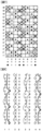
- FIG. 1 to 8 is a design view showing a complete structure of embodiments 1 to 4 of the present invention.
- the design view corresponds to the complete structure of the fabric defining the minimum unit to be repeated of the fabric structure.
- the final product is completed by combining any number of such complete structures in the longitudinal direction and the direction perpendicular to the longitudinal direction.
- the warp is indicated by a reference number such as 1,2,3 .
- a first pair of warps consisting of a warp on the front surface side and a warp on the back surface side, and a second pair of warps in which two sets of two biding warps are arranged to be adjacent to each other are shown.
- the weft is indicated by a reference number such as 1',2' ,3' .
- a symbol “ ⁇ ” indicates that the warp on the front surface side is arranged above the weft on the front surface side.
- a symbol “ ⁇ ” indicates that the warp on the back surface side is arranged below the weft on the back surface side.
- a symbol “ ⁇ ” indicates that the binding warp on the back surface side is arranged below the weft on the back surface side.
- a symbol “ ⁇ ” indicates that the binding warp on the back surface side is arranged above the weft on the front surface side.
- a symbol “ ⁇ ” indicates that the binding warp on the front surface side is arranged below the weft on the back surface side.
- a symbol “ ⁇ ” indicates that the binding warp on the front surface side is arranged below the weft on the front surface side.
- the warps and the wefts on the upper surface side are arranged to be overlapped with the warps and the wefts on the lower surface side, respectively.
- the warps and the wefts on the upper surface side are depicted to be precisely arranged over the warps and the wefts on the upper surface side, because of the clarity of the drawing. In the real fabric, it does not matter if they are arranged to be offset.
- Fig.1 is a design view showing a complete structure of the first embodiment according to the industrial two-layered fabric of the present invention.
- a complete structure of the industrial two-layered fabric according to the embodiment 1 includes a first pair of warps consisting of warps (1,4,5,8,9,12) on the front surface side and warps (1,4,5,8,9,12) on the back surface side which does not include the binding warps and a second pair of warps consisting of binding warps (2,3,6,7,10,11) on the front surface side and binding warps (2,3,6,7,10,11) on the back surface side which includes a binding functions.
- the first pair 1 of warps are alternately woven with the wefts on the front surface side in such a way that the warp on the front surface side forms a plain weaving on the fabric on the front surface side, while the warps on the back surface side are woven with the wefts on the back surface side, as shown in the warps 1 on the back surface side in Fig.2 , and as a result, a 1/4-1/3 structure is formed on the fabric on the back surface side.
- a second pair of warps never fails to be arranged at a position adjacent to each of the first pair of warps.
- two sets 2,3 of a second pair of warps are arranged at a position adjacent to each of the first pair 1 of warps.
- the binding warp 2 among the second pair 2,3 of warps passes below the weft 1' on the front surface side, above the wefts 2' ,4' on the front surface side, below the wefts 7' ,11' on the back surface side, and above the wefts 14' 16' ,18' on the front surface side to form a knuckle, while the binding warp 2 on the back surfaces side among the second pair 2,3 of warps passes above the weft 1' on the back surface side, below the weft 2' on the back surface side, above the wefts 6' ,8' , 10', 12' on the front surface side, and below the weft 16' on the back surface side to bind the fabric on the front surface side with the fabric on the back surface side.
- the second pair 2,3 of warps are arranged to be adjacent to the first pair 4 of warps.
- the warp 4 in the first pair of warps forms a plain weaving on the fabric on the front surface side.
- the binding warp 3 on the front surface side among the second pair 2,3 of warps passes above the wefts 1', 3', 5', 7' on the front surface side, below the wefts 10' ,14' on the back surface side, and above the weft 17' on the front surface side to form a knuckle, while the binding warp 3 on the back surfaces side among the second pair 2,3 of warps passes below the wefts 1',5' on the back surface side, and above the wefts 9', 11', 13', 15' on the back surface side to bind the fabric on the front surface side with the fabric on the back surface side.
- the second pair 6,7 of warps are arranged to be adjacent to the first pair 5 of warps.
- the second pair 6,7 of warps are also arranged to be adjacent to the first pair 8 of warps.
- the second pair 10,11 of warps are arranged to be adjacent to the first pair 9 of warps, while the second pair 10,11 of warps are also arranged to be adjacent to the first pair 12 of warps.
- the uniform hydration speed can be secured, so that the generation of the hydration marks can be decreased.
- the abrasion resistance on the back surface side and the extension resistance in the longitudinal direction can be improved, so that the adhesive property between the fabric on the front surface side and the fabric on the back surface side can be enhanced.
- Fig.2 is a design view showing a complete structure of the second embodiment according to the industrial two-layered fabric of the present invention.
- a complete structure of the industrial two-layered fabric according to the embodiment 2 includes a first pair of warps consisting of warps (1,4,5,8,9,12) on the front surface side and warps (1,4,5,8,9,12) on the back surface side which does not include the binding warps and a second pair of warps consisting of binding warps (2,3,6,7,10,11) on the front surface side and binding warps (2,3,6,7,10,11) on the back surface side which includes binding functions.
- the first pair 1 of warps are alternately woven with the wefts on the front surface side in such a way that the warp on the front surface side forms a plain weaving on the fabric on the front surface side, while the warps on the back surface side are woven with the wefts on the back surface side, as shown in the warps 1 on the back surface side in Fig.4 , and as a result, a 1/4-1/3 structure is formed on the fabric on the back surface side.
- a second pair of warps never fails to be arranged at a position adjacent to each of the first pair of warps.
- two sets 2,3 of a second pair of warps are arranged at a position adjacent to each of the first pair 1 of warps.
- the binding warp 2 among the second pair 2,3 of warps passes below the weft 1' on the front surface side, above the weft 2' ,4' on the front surface side, below the weft 7' on the back surface side, and above the weft 10' 12' ,14', 16' ,18' on the front surface side to form a knuckle, while the binding warp 2 on the back surfaces side among the second pair 2,3 of warps passes above the weft 1' on the back surface side, below the weft 2' on the back surface side, above the wefts 6' ,8' on the front surface side, and below the wefts 11' ,16' on the back surface side to bind the fabric on the front surface side with the fabric on the back surface side.
- the second pair 2,3 of warps are arranged to be adjacent to the first pair 4 of warps.
- the warp 4 in the first pair of warps forms a plain weaving on the fabric on the front surface side.
- the binding warp 3 on the front surface side among the second pair 2,3 of warps passes above the wefts 1', 3', 5', 7' , 9', 11' on the front surface side, below the weft 14' on the back surface side, and above the weft 17' on the front surface side to form a knuckle, while the binding warp 3 on the back surfaces side among the second pair 2,3 of warps passes below the wefts 1', 5' ,10' on the back surface side, and above the wefts 13', 15' on the back surface side to bind the fabric on the front surface side with the fabric on the back surface side.
- the second pair 6,7 of warps are arranged to be adjacent to the first pair 5 of warps.
- the second pair 6,7 of warps are also arranged to be adjacent to the first pair 8 of warps.
- the second pair 10,11 of warps are arranged to be adjacent to the first pair 9 of warps, while the second pair 10,11 of warps are also arranged to be adjacent to the first pair 12 of warps.
- the uniform hydration speed can be secured, so that the generation of the hydration marks can be decreased.
- the abrasion resistance on the back surface side and the extension resistance in the longitudinal direction can be improved, so that the adhesive property between the fabric on the front surface side and the fabric on the back surface side can be enhanced.
- Fig.5 is a design view showing a complete structure of the third embodiment according to the industrial two-layered fabric of the present invention.
- a complete structure of the industrial two-layered fabric according to the embodiment 3 includes a first pair of warps consisting of warps (1,4,5,8) on the front surface side and warps (1,4,5,8) on the back surface side which does not include the binding warps and a second pair of warps consisting of binding warps (2,3,6,7) on the front surface side and binding warps (2,3,6,7) on the back surface side which includes a binding functions.
- the first pair 1 of warps are alternately woven with the wefts on the front surface side in such a way that the warp on the front surface side forms a plain weaving on the fabric on the front surface side, while the warps on the back surface side are woven with the wefts on the back surface side, as shown in the warps 1 on the back surface side in Fig.6 , and as a result, a 1/4-1/4-1/5 structure is formed on the fabric on the back surface side.
- a second pair of warps never fails to be arranged at a position adjacent to each of the first pair of warps.
- two sets (2,3) of a second pair of warps are arranged at a position adjacent to each of the first pair 1 of warps.
- the uniform hydration speed can be secured, so that the generation of the hydration marks can be decreased.
- the abrasion resistance on the back surface side and the extension resistance in the longitudinal direction can be improved, so that the adhesive property between the fabric on the front surface side and the fabric on the back surface side can be enhanced.
- Fig.1 is a design view showing a complete structure of the first embodiment according to the industrial two-layered fabric of the present invention.
- a complete structure of the industrial two-layered fabric according to the embodiment 1 includes a first pair of warps consisting of warps (1,4,5,8,9,12) on the front surface side and warps (1,4,5,8,9,12) on the back surface side which does not include the binding warps and a second pair of warps consisting of binding warps (2,3,6,7,10,11) on the front surface side and binding warps (2,3,6,7,10,11) on the back surface side which includes a binding functions.
- the first pair 1 of the warps are woven with the wefts on the front surface side ins such a way that the warps on the front surface side form a 2/2 structure on the fabric on the front surface side, while the warps on the back surface side are woven with the wefts on the back surface side, as shown in Fig.8 , to form a 1/4-1/4-1/5 structure.
- the first pair 5 of the warps also includes the same structure.
- first pair 4 of the warps are alternately woven with the wefts on the front surface side in such a way that the warp on the front surface side forms a plain weaving on the fabric on the front surface side, while the warps on the back surface side are woven with the wefts on the back surface side, as shown in the warps 4 on the back surface side in Fig.8 , and as a result, a 1/4-1/4-1/5 structure is formed on the fabric on the back surface side.
- the first pair 8 of the warps also includes the same structure.
- a second pair of warps never fails to be arranged at a position adjacent to each of the first pair of warps.
- two sets (2,3) of a second pair of warps are arranged at a position adjacent to each of the first pair 1 of warps.
- the binding warp 2 among the second pair 2,3 of warps passes above the wefts 2' ,4' ,6' ,8' on the front surface side, below the weft 11' on the back surface side, and above the weft 16' on the front surface side, while the binding warp 2 on the back surfaces side among the second pair 2,3 of warps passes below the wefts 1', 6'on the back surface side, and above the wefts 10' ,12' ,14' on the front surface side, to bind the fabric on the front surface side with the fabric on the back surface side.
- the second pair 2,3 of warps are arranged to be adjacent to the first pair 4 of warps.
- the binding warp 3 on the front surface side among the second pair 2,3 of warps passes above the wefts 1', 2' on the front surface side, below the wefts 5' ,10' on the back surface side, and above the wefts 13',14' on the front surface side, while the binding warp 3 on the back surfaces side among the second pair 2,3 of warps passes above the wefts 5',6' on the back surface side, below the wefts 7', 8' on the back surface side, the wefts 9',10' on the front surface side, and below the weft 15',6' on the back surface side to bind the fabric on the front surface side with the fabric on the back surface side.
- the second pair 6,7 of warps are arranged to be adjacent to the first pair 5 of warps.
- the second pair 6,7 of warps are also arranged to be adjacent to the first pair 8 of warps.
- the uniform hydration speed can be secured, so that the generation of the hydration marks can be decreased.
- the abrasion resistance on the back surface side and the extension resistance in the longitudinal direction can be improved, so that the adhesive property between the fabric on the front surface side and the fabric on the back surface side can be enhanced.
Landscapes
- Engineering & Computer Science (AREA)
- Textile Engineering (AREA)
- Woven Fabrics (AREA)
- Paper (AREA)
Description
- The present invention relates to an industrial two-layered fabric including binding warps which is capable of improving an adhesive property between a fabric on a front surface side and a fabric on a back surface side and a supporting force of a weft, while at the same time, of decreasing hydration marks generated on a paper to be produced.
- Fabrics obtained by weaving warps and wefts have conventionally been used widely as an industrial fabric. They are, for example, used in various fields including papermaking fabrics, conveyor belts and filter cloths and are required to have fabric properties suited for the intended use or using environments. Of such fabrics, a papermaking fabric used in a papermaking step for removing water from raw materials by making use of the network of the fabric must satisfy a severe demand.
- For example, there is a demand for the development of fabrics which do not transfer a wire mark of the fabric and therefore have excellent surface property, the ones which have enough hydration property for sufficiently and uniformly hydrating excess water contained in the material and enough rigidity or wear resistance to be usable desirably even under severe environments, or the ones which are capable of maintaining conditions necessary for making good paper for a prolonged period of time.
- In addition, fiber supporting property, improvement in a paper making yield, dimensional stability and running stability are demanded.
- In recent years, owing to the speed-up of a paper making machine, requirements for papermaking fabrics become severe further.
- Since most of the demands for industrial fabrics and solutions thereof can be understood if papermaking fabrics on which the most severe demand is imposed among industrial fabrics is described, the papermaking fabric will hereinafter be described as a representative example.
- In the industrial fabric in which the fabric on the front surface side and the fabric on the back surface side are bound by the binding warps, it is widely known that the portion where the fabric on the front surface side and the fabric on the back surface side contact become worn while they are run by the paper making machine. In particular, the generation of the inner abrasion increases due to the speed up of the paper making machine in recent years. In a case where the inner abrasion is caused, the degree of the ventilation of the net is deteriorated due to the fact that the surface of the yarns inside the fabric becomes fluffy, so that the hydration speed decreases.
- In order to prevent such an inner abrasion, a method of increasing an adhesive force between the fabric on the front surface side and the fabric on the back surface side is known. For instance, the method of increasing the number of the binding warps is disclosed as an example of such a method of increasing an adhesive force between the fabric on the front surface side and the fabric on the back surface side (refer to Patent publication 1).
- For instance, the adhesive force between the fabric on the front surface side and the fabric on the back surface side increases by increasing the number of the binding warps, since the number of the yarns binding the fabric on the front surface side and the fabric on the back surface side increases by increasing the binding ratio in the complete structure.
- However, the hydration mark tends to generate in the fabric on the front surface side by the increasing the binding ratio, according to the above method. More specifically, in the industrial fabric including the binding warps, it is general that a knuckle is not formed at the point where the knuckle is formed on the fabric on the front surface by the warps on the front surface side, but that the warps on the back surface side forms a knuckle on the fabric on the front surface side (refer to Patent publication 2).
- In a point where a knuckle on the front surface side is complemented by the warps on the back surface side, since the warps on the front surface side is caused to be collapsed, the density of the warps is substantially doubled. At the portion where the density of the warps is increased, the hydration is obstructed. In addition, in a case where the number of the binding warps and the ratio of the binding are increased in such a structure of the fabric, the hydration marks are formed on the surface of the paper to be produced, since the points of the obstruction of the hydration are evenly arranged, so that a line on which the obstruction of the hydration occurs is formed.
- In order not to make the hydration obstruction points by the binding warps densely crowded, a method of lengthening the longitudinal direction of the complete structure by increasing the number of the warps in the complete structure is known. The density of the hydration obstruction points can be lowered by such a structure. However, if such a structure is applied to the normal fabric, one single binding yarn consecutively forms a plurality of knuckles on the fabric on the front surface. In addition, in case of the fabric in which one single binding yarn consecutively forms a plurality of knuckles on the fabric on the front surface, it is known that the shape of the fabric is a mountain shape with the central portion of each of the plurality of knuckles being an apex. For instance, the warp passes above the weft to form a knuckle on the fabric on the front surface side.
- Such a fabric structure deforms into a mountain shape whose apex is the weft located to be center, due to the stress generated on the yarns. In addition, the warps can form a long knuckle on the plurality of wefts. Such a fabric structure can also deform into a mountain shape whose apex is the weft located to be center, due to the stress generated on the yarns.
- The portions protruding like a mountain can deteriorate the surface smoothness of the fabric in addition to the hydration marks. In order to solve such a technical problem, the fabric is disclosed in the
Patent Publication 3. Further, a structure in which two sets of binding wefts are arranged to be adjacent to each other can be devised, based on the fabric disclosed in thePatent Publication 3. - In the above fabric, in order to maintain the surface smoothness, it is necessary for the diameter of the binding warp to conform to that of the warp on the front surface side. In the above fabric, the binding warp is arranged to be adjacent to one or a plurality of upper and lower warps, and is woven so as to complement the fabric structure on the front and back surface sides, with making two binding warps to form a pair to repeatedly cross. Due to the above, the hydration path is blocked by the cross sections which are repeatedly formed in the longitudinal direction with a constant cycle, so that the hydration speed differs from that of other portions. The hydration marks can be caused on the paper due to the above action.
- In addition, in the industrial two-layered fabric including the binding warps, the wefts on the back surface side with a large diameter is normally adopted in order to deal with the abrasion. This leads to adopt the warp on the back surface with a large diameter. Such being the case, in a case where two or more yarns with large diameters are arranged, a wide space portion occupied by the binding warps located on a points where adjacent binding warps do not cross on the back surface side, and a narrow space portion occupied by the warps located on points where upper and lower warps with different diameters are generated, so that the hydration speeds differ, which causes the generation of the hydration marks to be accelerated.
- That is to say, since the fabric in which the fabric on the front surface side and the fabric on the back surface side are bound by the binding warps maintains the surface smoothness, it was necessary to make the surface fine and make the shape of the knuckles formed on the front surface uniform by adopting yarns with diameters small than that on the back surface side, as the warps on the front surface side and the wefts. In addition, it was necessary to bind the front surface side and the back surface side by forming the knuckles on both of the front and back surfaces by means of the binding warps, and, it was necessary to make the diameter of the binding warps conform to that of the warps on the front surface side in order to maintain the surface smoothness.
- In addition, it is necessary to make the diameter of the weft on the back surface side large in order to improve the rigidity and the abrasion resistance of the fabric and restrict its extension in the longitudinal direction. Further, it was necessary to make the diameter of the warp on the back surface side large in order to weave the warp on the back surface side with the weft on the back surface side with a large diameter. Still further, with respect to the arrangement of the yarns, it is normal to make the warp on the front surface side and the warp on the back surface side a pair to arrange a couple of the binding warps on the front surface side and the binding warp on the back surface side therebetween, and to set the ratio of the warps on the back surface side to the binding warps on the back surface side to be 1/1. And as a result, the space occupied by the binding portion and the space occupied by the warps on the front and back surface sides differ, so that the cycle in which the biding warps cross becomes long, whereby the generation of the hydration marks can be accelerated.
-
- Patent Publication 1:
Japanese Patent Laid-open Publication 2001-98483 - Patent Publication 2:
Japanese Patent Laid-open Publication 2003-342889 - Patent Publication 3:
Japanese Patent Laid-open Publication 2006-57216 -
EP 1 630 270 A2 -
WO 2017/126234 A1 relates to an industrial textile. The present document provides an industrial textile in which an upper surface textile made from upper surface warp yarns and upper surface weft yarns is joined to a lower surface textile made from lower surface warp yarns and lower surface weft yarns by binding yarns, said industrial textile being configured so as to be characterized in: having depression in-drawing binding yarns with portions that form single knuckles in the upper surface textile; disposing depression up-pushing binding yarns at places adjacent to the depression in-drawing binding yarns; and forming two knuckles by interweaving the depression up-pushing binding yarns with the upper surface warp yarns or upper surface weft yarns that are disposed on both sides, in the yarn direction, of the upper surface warp yarn or upper surface weft yarn that is interwoven at the portions of the depression in-drawing binding yarns where single knuckles are formed. Thus, depressions that occur on the upper surface of the textile are systematically subdivided, and it is possible to prevent markings that occur successivelty in an oblique direction on the surface of a sheet-making product that is produced. -
EP 1 659 212 A2figure 5 ofEP 1 659 212 A2EP 1 659 212 A2 - The object of the present invention is to provide an industrial two-layered fabric including binding warps which is capable of improving a high adhesivity of the fabric on the front and back surface sides and the supportability of the warps, without deteriorating the surface smoothness, the abrasion resistance on the back surface side, the extension resistance in the longitudinal direction and the hydration property, which have been conventionally desired.
- The object of the present invention is to provide an industrial two-layered fabric including binding wefts which is capable of decreasing the abrasion of the binding yarns by changing the arrangement of the warps and the binding warps, while at the same time, of decreasing the generation of the hydration marks by means of an even hydration.
- The industrial two-layered fabric of the present invention includes the technical features of
claim 1 to solve the above technical problems. - In the present invention, the rigidity and the abrasion resistance of the fabric can be improved by adopting such a structure. In short, in the industrial two-layered fabric of the present invention, since the diameter of the warp on the back surface side is be larger than that of the warp on the front surface side, the diameter of the weft on the back surface side woven with the warp with a large diameter can be also thickened.
- In the present invention, the abrasion resistance of the binding yarn can be high by the arrangement of the warp and the binding warp.
- In the industrial two-layered fabric of the present invention, the ratio of the warps on the front surface side to the warps on the back surface side may be 1:1.
- In the industrial two-layered fabric of the present invention, two sets of the second pair of the warps are arranged to be adjacent to each other, and a first pair of warps is arranged on each side of the second pair of the warps, and such an arrangement is repeated.
- In such a structure, because two sets of the second pair of the warps are arranged to be adjacent to each other, in total four binding warps are adjacently arranged.
- A first pair of warps is arranged on each side of the second pair of the warps.
- More specifically, four sets of the pair of warps are repeatedly arranged.
- In the present invention, the technical problem that the generation of the hydration mark is accelerated is solved. More specifically, since two sets of the second pair of the warps including binding portion are arranged to be adjacent to the first pair of warps, and such a pattern is repeated, one or more binding yarns with a small dimeter never fails to be arranged to be adjacent to the one weft on the back surface side, an uniform hydration is attained by the block of the hydration path being restricted, so that the generation of the hydration marks can be decreased.
- In the industrial two-layered fabric of the present invention, the cross sectional shape of the weft on the front surface side, the warp on the front surface side, the weft on the back surface side, the warp on the back surface side, or the binding warp may be circle, square or short form such as stellar form, or elliptical.
- By adopting industrial two-layered fabric of the present invention, the industrial two-layered fabric including binding warps which is capable of improving a high adhesivity of the fabric on the front and back surface sides and the supportability of the wefts, without deteriorating the surface smoothness, the abrasion resistance on the back surface side, the extension resistance in the longitudinal direction and the hydration property can be provided.
- By adopting industrial two-layered fabric of the present invention, the industrial two-layered fabric including binding warps which is capable of decreasing the abrasion of the binding yarns by changing the arrangement of the warps and the binding warps, while at the same time, of decreasing the generation of the hydration marks by means of an even hydration can be provided.
-
-
Fig. 1 is a design view showing a complete structure of the first embodiment according to the industrial two-layered fabric of the present invention. -
Fig.2 is a view showing a cross section in the warp direction of thepairs 1 to 4 of the warps of the first embodiment illustrated inFig. 1 . -
Fig.3 is a design view showing a complete structure of the second embodiment according to the industrial two-layered fabric of present invention. -
Fig.4 is a view showing a cross section in the warp direction of thepairs 1 to 4 of the warps of the second embodiment illustrated inFig.3 . -
Fig.5 is a design view showing a complete structure of the third embodiment according to the industrial two-layered fabric of present invention. -
Fig.6 is a view showing a cross section in the warp direction of thepairs 1 to 4 of the warps of the third embodiment illustrated inFig.5 . -
Fig.7 is a design view showing a complete structure of the fourth embodiment according to the industrial two-layered fabric of present invention. -
Fig.8 is a view showing a cross section in the warp direction of thepairs 1 to 4 of the warps of the fourth embodiment illustrated inFig.7 . - Now, the structure and the effect of the two-layered fabric of the present invention will be described below. Embodiments of the two-layered fabric of the present invention will be described thereafter with reference to the drawings.
- In the industrial two-layered fabric with a complete structure of the present invention, a fabric on a front surface side consisting of a weft on the front surface side and a warp on the front surface side and a fabric on a back surface side consisting of a weft on the back surface side and a warp on the back surface side are bound by a binding warp. In the industrial two-layered fabric includes a first pair of warps consisting of a warp on the front surface side and a warp on the back surface side, and a second pair of warps which two binding warps are arranged to be adjacent to each other so as to function to bind the fabric on the front surface side and the fabric on the back surface side.
- The one of the binding warp constituting the second pair of the warps consecutively forms a plurality of knuckles on the fabric on the front surface side, while the other of the binding warps does not emerge on the front surface side at a portion where a plurality of knuckles are formed, and the other binding warp consecutively forms a plurality of knuckles on the fabric on the front surface side, while the one binding warp does not emerge on the front surface side, whereby a complementary structure is formed. That is to say, the second pair of warps forms one structure on the fabric on the front surface side by the complementing of two binding warps. Further, the binding warps can be defined to be the binding warps which functions as the binding yarn with mainly being woven with the front surface side, or the binding warps which functions as the binding yarn with mainly being woven with the back surface side.
- In addition, the diameter of the warp on the front surface side is set to be substantially the same as that of the binding warp, and the diameter of the warp on the back surface side is set to be larger than that of the binding warp on the front surface side. The complete structure of the present invention in the industrial two-layered fabric includes eight or more shafts.
- In the complete structure of the present invention in the industrial two-layered fabric, two sets of the second pair of the warps are arranged to be adjacent to each other, and a first pair of warps is arranged on each side of the second pair of the warps, and such an arrangement is repeated.
- In the complete structure of the present invention in the industrial two-layered fabric, the ratio of the warps on the front surface side to the wefts on the back surface side may be 1:1.
- No particular limitation is imposed on a yarn to be used in the present invention and it can be selected freely depending on the properties which an industrial fabric is desired to have. Examples of it include, in addition to monofilaments, multifilaments, spun yarns, finished yarns subjected to crimping or bulking such as so-called textured yarn, bulky yarn and stretch yarn, and yarns obtained by intertwining them. As the cross-section of the yarn, not only circular form but also square or short form such as stellar form, or elliptical or hollow form can be used. The material of the yarn can be selected freely and usable examples of it include polyester, polyamide, polyphenylene sulfide, polyvinylidene fluoride, polypropylene, aramid, polyether ketone, polyethylene naphthalate, polytetrafluoroethylene, cotton, wool and metal. Of course, yarns obtained using copolymers or incorporating or mixing the above-described material with a substance selected depending on the intended purpose may be used.
- As the upper surface side warps, lower surface side warps, and upper surface side wefts, use of a polyester monofilament having rigidity and excellent dimensional stability is usually preferred. When lower surface side wefts which need wear resistance are obtained by interweaving of polyester monofilaments and polyamide monofilaments while arranging them alternately, they are able to have wear resistance without losing rigidity.
- It is also possible to place a plurality of yarns with the same design at a position where one yarn is normally placed from the standpoint of design. Design of a plurality of yarns having a thin diameter brings about improvement in surface property and thinning of the fabric.
- Now, the embodiments of the present invention will be described below. Each of the embodiments described below is an example of the present invention which does not limit the scope of the present invention.
- The embodiments of the present invention will be described below with reference to the drawings. Each of
Figs.1 to 8 is a design view showing a complete structure ofembodiments 1 to 4 of the present invention. Here, the design view corresponds to the complete structure of the fabric defining the minimum unit to be repeated of the fabric structure. The final product is completed by combining any number of such complete structures in the longitudinal direction and the direction perpendicular to the longitudinal direction. - In each of the design views, the warp is indicated by a reference number such as 1,2,3 ...... In the embodiments, a first pair of warps consisting of a warp on the front surface side and a warp on the back surface side, and a second pair of warps in which two sets of two biding warps are arranged to be adjacent to each other are shown. The weft is indicated by a reference number such as 1',2' ,3' ......
- In addition, in each of the design views, a symbol "×" indicates that the warp on the front surface side is arranged above the weft on the front surface side. A symbol "○" indicates that the warp on the back surface side is arranged below the weft on the back surface side. A symbol "□" indicates that the binding warp on the back surface side is arranged below the weft on the back surface side. A symbol "▲" indicates that the binding warp on the back surface side is arranged above the weft on the front surface side. A symbol "△" indicates that the binding warp on the front surface side is arranged below the weft on the back surface side. A symbol "■" indicates that the binding warp on the front surface side is arranged below the weft on the front surface side. The warps and the wefts on the upper surface side are arranged to be overlapped with the warps and the wefts on the lower surface side, respectively. In this connection, in the design view, the warps and the wefts on the upper surface side are depicted to be precisely arranged over the warps and the wefts on the upper surface side, because of the clarity of the drawing. In the real fabric, it does not matter if they are arranged to be offset.
-
Fig.1 is a design view showing a complete structure of the first embodiment according to the industrial two-layered fabric of the present invention. A complete structure of the industrial two-layered fabric according to theembodiment 1 includes a first pair of warps consisting of warps (1,4,5,8,9,12) on the front surface side and warps (1,4,5,8,9,12) on the back surface side which does not include the binding warps and a second pair of warps consisting of binding warps (2,3,6,7,10,11) on the front surface side and binding warps (2,3,6,7,10,11) on the back surface side which includes a binding functions. - The
first pair 1 of warps are alternately woven with the wefts on the front surface side in such a way that the warp on the front surface side forms a plain weaving on the fabric on the front surface side, while the warps on the back surface side are woven with the wefts on the back surface side, as shown in thewarps 1 on the back surface side inFig.2 , and as a result, a 1/4-1/3 structure is formed on the fabric on the back surface side. - In addition, a second pair of warps never fails to be arranged at a position adjacent to each of the first pair of warps. For instance, two
sets first pair 1 of warps. More specifically, as shown inFig.2 , thebinding warp 2 among thesecond pair binding warp 2 on the back surfaces side among thesecond pair - In addition, the
second pair first pair 4 of warps. Thewarp 4 in the first pair of warps forms a plain weaving on the fabric on the front surface side. Thebinding warp 3 on the front surface side among thesecond pair binding warp 3 on the back surfaces side among thesecond pair - Further, the
second pair first pair 5 of warps. Thesecond pair first pair 8 of warps. Thesecond pair first pair 9 of warps, while thesecond pair first pair 12 of warps. - By adopting such a structure, since the binding warps with small diameters never fails to be arranged to be adjacent to the warps on the back surface side with large dimeters, the uniform hydration speed can be secured, so that the generation of the hydration marks can be decreased. In addition, the abrasion resistance on the back surface side and the extension resistance in the longitudinal direction can be improved, so that the adhesive property between the fabric on the front surface side and the fabric on the back surface side can be enhanced.
-
Fig.2 is a design view showing a complete structure of the second embodiment according to the industrial two-layered fabric of the present invention. A complete structure of the industrial two-layered fabric according to theembodiment 2 includes a first pair of warps consisting of warps (1,4,5,8,9,12) on the front surface side and warps (1,4,5,8,9,12) on the back surface side which does not include the binding warps and a second pair of warps consisting of binding warps (2,3,6,7,10,11) on the front surface side and binding warps (2,3,6,7,10,11) on the back surface side which includes binding functions. - The
first pair 1 of warps are alternately woven with the wefts on the front surface side in such a way that the warp on the front surface side forms a plain weaving on the fabric on the front surface side, while the warps on the back surface side are woven with the wefts on the back surface side, as shown in thewarps 1 on the back surface side inFig.4 , and as a result, a 1/4-1/3 structure is formed on the fabric on the back surface side. - In addition, a second pair of warps never fails to be arranged at a position adjacent to each of the first pair of warps. For instance, two
sets first pair 1 of warps. More specifically, as shown inFig.4 , thebinding warp 2 among thesecond pair binding warp 2 on the back surfaces side among thesecond pair - In addition, the
second pair first pair 4 of warps. Thewarp 4 in the first pair of warps forms a plain weaving on the fabric on the front surface side. Thebinding warp 3 on the front surface side among thesecond pair binding warp 3 on the back surfaces side among thesecond pair - Further, the
second pair first pair 5 of warps. Thesecond pair first pair 8 of warps. Thesecond pair first pair 9 of warps, while thesecond pair first pair 12 of warps. - By adopting such a structure, since the binding warps with small diameters never fails to be arranged to be adjacent to the warps on the back surface side with large dimeters, the uniform hydration speed can be secured, so that the generation of the hydration marks can be decreased. In addition, the abrasion resistance on the back surface side and the extension resistance in the longitudinal direction can be improved, so that the adhesive property between the fabric on the front surface side and the fabric on the back surface side can be enhanced.
-
Fig.5 is a design view showing a complete structure of the third embodiment according to the industrial two-layered fabric of the present invention. A complete structure of the industrial two-layered fabric according to theembodiment 3 includes a first pair of warps consisting of warps (1,4,5,8) on the front surface side and warps (1,4,5,8) on the back surface side which does not include the binding warps and a second pair of warps consisting of binding warps (2,3,6,7) on the front surface side and binding warps (2,3,6,7) on the back surface side which includes a binding functions. - The
first pair 1 of warps are alternately woven with the wefts on the front surface side in such a way that the warp on the front surface side forms a plain weaving on the fabric on the front surface side, while the warps on the back surface side are woven with the wefts on the back surface side, as shown in thewarps 1 on the back surface side inFig.6 , and as a result, a 1/4-1/4-1/5 structure is formed on the fabric on the back surface side. - In addition, a second pair of warps never fails to be arranged at a position adjacent to each of the first pair of warps. For instance, two sets (2,3) of a second pair of warps are arranged at a position adjacent to each of the
first pair 1 of warps. More specifically, as shown inFig.5 , thebinding warp 2 among thesecond pair binding warp 2 on the back surfaces side among thesecond pair - In addition, the
second pair first pair 4 of warps. Thebinding warp 3 on the front surface side among thesecond pair binding warp 3 on the back surfaces side among thesecond pair - Further, the
second pair first pair 5 of warps. Thesecond pair first pair 8 of warps. - By adopting such a structure, since the binding warps with small diameters never fails to be arranged to be adjacent to the warps on the back surface side with large dimeters, the uniform hydration speed can be secured, so that the generation of the hydration marks can be decreased. In addition, the abrasion resistance on the back surface side and the extension resistance in the longitudinal direction can be improved, so that the adhesive property between the fabric on the front surface side and the fabric on the back surface side can be enhanced.
-
Fig.1 is a design view showing a complete structure of the first embodiment according to the industrial two-layered fabric of the present invention. A complete structure of the industrial two-layered fabric according to theembodiment 1 includes a first pair of warps consisting of warps (1,4,5,8,9,12) on the front surface side and warps (1,4,5,8,9,12) on the back surface side which does not include the binding warps and a second pair of warps consisting of binding warps (2,3,6,7,10,11) on the front surface side and binding warps (2,3,6,7,10,11) on the back surface side which includes a binding functions. - The
first pair 1 of the warps are woven with the wefts on the front surface side ins such a way that the warps on the front surface side form a 2/2 structure on the fabric on the front surface side, while the warps on the back surface side are woven with the wefts on the back surface side, as shown inFig.8 , to form a 1/4-1/4-1/5 structure. Thefirst pair 5 of the warps also includes the same structure. In addition, thefirst pair 4 of the warps are alternately woven with the wefts on the front surface side in such a way that the warp on the front surface side forms a plain weaving on the fabric on the front surface side, while the warps on the back surface side are woven with the wefts on the back surface side, as shown in thewarps 4 on the back surface side inFig.8 , and as a result, a 1/4-1/4-1/5 structure is formed on the fabric on the back surface side. Thefirst pair 8 of the warps also includes the same structure. - In addition, a second pair of warps never fails to be arranged at a position adjacent to each of the first pair of warps. For instance, two sets (2,3) of a second pair of warps are arranged at a position adjacent to each of the
first pair 1 of warps. More specifically, as shown inFig.8 , thebinding warp 2 among thesecond pair binding warp 2 on the back surfaces side among thesecond pair - In addition, the
second pair first pair 4 of warps. Thebinding warp 3 on the front surface side among thesecond pair binding warp 3 on the back surfaces side among thesecond pair - Further, the
second pair first pair 5 of warps. Thesecond pair first pair 8 of warps. - By adopting such a structure, since the binding warps with small diameters never fails to be arranged to be adjacent to the warps on the back surface side with large dimeters, the uniform hydration speed can be secured, so that the generation of the hydration marks can be decreased. In addition, the abrasion resistance on the back surface side and the extension resistance in the longitudinal direction can be improved, so that the adhesive property between the fabric on the front surface side and the fabric on the back surface side can be enhanced.
-
- 1~12: warp
- 1'~18': weft
Claims (3)
- An industrial two-layered fabric with a complete structure, including:
a fabric on a front surface side consisting of a weft on the front surface side and a warp on the front surface side;a fabric on a back surface side consisting of a weft on the back surface side and a warp on the back surface side, the fabric on a front surface side and the fabric on a back surface side are bound by a binding warp;first pairs (1, 4) of warps consisting of a warp on the front surface side that weaves only the weft on the front surface side and a warp on the back surface side that weaves only the weft on the back surface side; andsecond pairs (2, 3) of warps consisting of a binding warp on the front surface side and a binding warp on the back surface side, which functions to bind the fabric on the front surface side and the fabric on the back surface side,wherein the one of the binding warp constituting each one of the second pairs (2, 3) of the warps consecutively forms a plurality of knuckles on the fabric on the front surface side, while the other of the binding warps does not emerge on the front surface side at a portion where a plurality of knuckles are formed by the one of the binding warp, andthe other binding warp consecutively forms a plurality of knuckles on the fabric on the front surface side, while the one binding warp does not emerge on the front surface side at a portion where a plurality of knuckles are formed by the other of the binding warp, whereby a complementary structure is formed,wherein two adjacent ones of the second pairs (2, 3) of warps are arranged between two of the first pairs (1, 4) of warps, wherein each of the two second pairs (2, 3) of warps is arranged to be adjacent to one of the first pairs (1, 4) of warps, and such an arrangement is repeated,wherein the binding warp on the back surface side among the second pairs (2, 3) of the warps passes below the wefts on the back surface side,wherein the diameter of the warp that weaves only the weft on the front surface side is set to be substantially the same as the diameter of the binding warp, andwherein the diameter of the warp that weaves only the weft on the back surface side is set to be larger than the diameter of the binding warp. - The industrial two-layered fabric according to claim 1, wherein the cross sectional shape of the warp on the front surface side, the weft on the front surface side, the weft on the back surface side, the warp on the back surface side, or the binding warp is circle, square or short form such as stellar form, or elliptical.
- The industrial two-layered fabric according to claim 1,
wherein the ratio of the warps on the front surface side to the warps on the back surface side is 1:1.
Applications Claiming Priority (2)
| Application Number | Priority Date | Filing Date | Title |
|---|---|---|---|
| JP2018067046A JP7199820B2 (en) | 2018-03-30 | 2018-03-30 | industrial double layer fabric |
| PCT/JP2019/010206 WO2019188278A1 (en) | 2018-03-30 | 2019-03-13 | Industrial two-layer fabric |
Publications (4)
| Publication Number | Publication Date |
|---|---|
| EP3779036A1 EP3779036A1 (en) | 2021-02-17 |
| EP3779036A4 EP3779036A4 (en) | 2021-08-25 |
| EP3779036C0 EP3779036C0 (en) | 2025-05-07 |
| EP3779036B1 true EP3779036B1 (en) | 2025-05-07 |
Family
ID=68061476
Family Applications (1)
| Application Number | Title | Priority Date | Filing Date |
|---|---|---|---|
| EP19776203.2A Active EP3779036B1 (en) | 2018-03-30 | 2019-03-13 | Industrial two-layer fabric |
Country Status (6)
| Country | Link |
|---|---|
| US (2) | US11668049B2 (en) |
| EP (1) | EP3779036B1 (en) |
| JP (2) | JP7199820B2 (en) |
| CN (2) | CN112041501B (en) |
| CA (1) | CA3095544A1 (en) |
| WO (1) | WO2019188278A1 (en) |
Families Citing this family (4)
| Publication number | Priority date | Publication date | Assignee | Title |
|---|---|---|---|---|
| DE102021115275A1 (en) * | 2021-06-14 | 2022-12-15 | Voith Patent Gmbh | Paper machine clothing and use of such clothing |
| JP7515442B2 (en) * | 2021-07-02 | 2024-07-12 | 日本フイルコン株式会社 | Industrial Fabrics |
| JP7515443B2 (en) * | 2021-07-21 | 2024-07-12 | 日本フイルコン株式会社 | Industrial Fabrics |
| JP7781033B2 (en) * | 2022-08-05 | 2025-12-05 | 日本フイルコン株式会社 | industrial textiles |
Citations (1)
| Publication number | Priority date | Publication date | Assignee | Title |
|---|---|---|---|---|
| EP1659212B1 (en) * | 2004-11-17 | 2011-02-16 | Nippon Filcon Co., Ltd. | Industrial two-layer fabric |
Family Cites Families (11)
| Publication number | Priority date | Publication date | Assignee | Title |
|---|---|---|---|---|
| JP2001098483A (en) | 1999-09-30 | 2001-04-10 | Nippon Felt Co Ltd | Double layer fabric for papermaking |
| JP3925915B2 (en) | 2002-05-24 | 2007-06-06 | 日本フイルコン株式会社 | Industrial two-layer fabric |
| JP4481765B2 (en) | 2004-08-23 | 2010-06-16 | 日本フイルコン株式会社 | Industrial two-layer fabric |
| JP4440085B2 (en) | 2004-11-26 | 2010-03-24 | 日本フイルコン株式会社 | Industrial two-layer fabric |
| JP4570090B2 (en) * | 2005-05-19 | 2010-10-27 | 日本フイルコン株式会社 | Industrial two-layer fabric |
| EP2213787B1 (en) * | 2007-10-05 | 2019-12-04 | Nippon Filcon Co., Ltd. | Industrial two-layer fabric |
| US7861747B2 (en) * | 2008-02-19 | 2011-01-04 | Voith Patent Gmbh | Forming fabric having exchanging and/or binding warp yarns |
| DE102013106327B4 (en) * | 2013-06-18 | 2015-01-08 | Andritz Technology And Asset Management Gmbh | papermaker |
| JP6280325B2 (en) * | 2013-07-12 | 2018-02-14 | 日本フイルコン株式会社 | Industrial two-layer fabric |
| ES2879640T3 (en) * | 2015-03-30 | 2021-11-22 | Nippon Filcon Kk | Two-layer industrial fabric |
| JP6755097B2 (en) * | 2016-01-22 | 2020-09-16 | 日本フイルコン株式会社 | Industrial textiles |
-
2018
- 2018-03-30 JP JP2018067046A patent/JP7199820B2/en active Active
-
2019
- 2019-03-13 CN CN201980023501.2A patent/CN112041501B/en active Active
- 2019-03-13 WO PCT/JP2019/010206 patent/WO2019188278A1/en not_active Ceased
- 2019-03-13 EP EP19776203.2A patent/EP3779036B1/en active Active
- 2019-03-13 CN CN202310038654.2A patent/CN115821450B/en active Active
- 2019-03-13 CA CA3095544A patent/CA3095544A1/en active Pending
- 2019-03-13 US US17/044,116 patent/US11668049B2/en active Active
-
2022
- 2022-08-23 JP JP2022132412A patent/JP2022169683A/en active Pending
-
2023
- 2023-04-21 US US18/305,009 patent/US20230257938A1/en active Pending
Patent Citations (1)
| Publication number | Priority date | Publication date | Assignee | Title |
|---|---|---|---|---|
| EP1659212B1 (en) * | 2004-11-17 | 2011-02-16 | Nippon Filcon Co., Ltd. | Industrial two-layer fabric |
Also Published As
| Publication number | Publication date |
|---|---|
| CN115821450A (en) | 2023-03-21 |
| US11668049B2 (en) | 2023-06-06 |
| EP3779036A4 (en) | 2021-08-25 |
| US20230257938A1 (en) | 2023-08-17 |
| CN115821450B (en) | 2025-06-10 |
| EP3779036C0 (en) | 2025-05-07 |
| CN112041501B (en) | 2023-01-10 |
| BR112020019838A2 (en) | 2021-01-05 |
| WO2019188278A1 (en) | 2019-10-03 |
| JP2022169683A (en) | 2022-11-09 |
| EP3779036A1 (en) | 2021-02-17 |
| CN112041501A (en) | 2020-12-04 |
| US20210017709A1 (en) | 2021-01-21 |
| CA3095544A1 (en) | 2019-10-03 |
| JP7199820B2 (en) | 2023-01-06 |
| JP2019178437A (en) | 2019-10-17 |
Similar Documents
| Publication | Publication Date | Title |
|---|---|---|
| EP2213787B1 (en) | Industrial two-layer fabric | |
| US20230257938A1 (en) | Industrial two-layer fabric | |
| EP1659212B1 (en) | Industrial two-layer fabric | |
| CA2698917C (en) | Industrial two-layer fabric | |
| EP3754107A1 (en) | Industrial two-layer fabric | |
| JP4563260B2 (en) | Industrial two-layer fabric | |
| CA2516903C (en) | Industrial two-layer fabric | |
| US7426943B2 (en) | Industrial two-layer fabric | |
| EP2192226A2 (en) | Industrial two-layer fabric | |
| US8991440B2 (en) | Industrial two-layer fabric | |
| EP2458048B1 (en) | Industrial two-layer fabric | |
| EP3406791B1 (en) | Industrial textile | |
| EP3450599B1 (en) | Two-layer textile for nonwoven fabric | |
| CA2872263C (en) | Industrial two-layer fabric | |
| EP3511455A1 (en) | Industrial two-layer woven fabric | |
| EP3476989A1 (en) | Industrial two-layer woven fabric |
Legal Events
| Date | Code | Title | Description |
|---|---|---|---|
| STAA | Information on the status of an ep patent application or granted ep patent |
Free format text: STATUS: THE INTERNATIONAL PUBLICATION HAS BEEN MADE |
|
| PUAI | Public reference made under article 153(3) epc to a published international application that has entered the european phase |
Free format text: ORIGINAL CODE: 0009012 |
|
| STAA | Information on the status of an ep patent application or granted ep patent |
Free format text: STATUS: REQUEST FOR EXAMINATION WAS MADE |
|
| 17P | Request for examination filed |
Effective date: 20200910 |
|
| AK | Designated contracting states |
Kind code of ref document: A1 Designated state(s): AL AT BE BG CH CY CZ DE DK EE ES FI FR GB GR HR HU IE IS IT LI LT LU LV MC MK MT NL NO PL PT RO RS SE SI SK SM TR |
|
| AX | Request for extension of the european patent |
Extension state: BA ME |
|
| DAV | Request for validation of the european patent (deleted) | ||
| DAX | Request for extension of the european patent (deleted) | ||
| A4 | Supplementary search report drawn up and despatched |
Effective date: 20210726 |
|
| RIC1 | Information provided on ipc code assigned before grant |
Ipc: D21F 1/10 20060101AFI20210720BHEP Ipc: D03D 1/00 20060101ALI20210720BHEP Ipc: D03D 11/00 20060101ALI20210720BHEP Ipc: D21F 1/00 20060101ALI20210720BHEP |
|
| STAA | Information on the status of an ep patent application or granted ep patent |
Free format text: STATUS: EXAMINATION IS IN PROGRESS |
|
| 17Q | First examination report despatched |
Effective date: 20230621 |
|
| GRAP | Despatch of communication of intention to grant a patent |
Free format text: ORIGINAL CODE: EPIDOSNIGR1 |
|
| STAA | Information on the status of an ep patent application or granted ep patent |
Free format text: STATUS: GRANT OF PATENT IS INTENDED |
|
| RIN1 | Information on inventor provided before grant (corrected) |
Inventor name: YANAI, HIDEYUKI Inventor name: EGAWA, TORU Inventor name: NOMURA, KUNIO Inventor name: UEDA, IKUO |
|
| INTG | Intention to grant announced |
Effective date: 20241219 |
|
| GRAS | Grant fee paid |
Free format text: ORIGINAL CODE: EPIDOSNIGR3 |
|
| GRAA | (expected) grant |
Free format text: ORIGINAL CODE: 0009210 |
|
| STAA | Information on the status of an ep patent application or granted ep patent |
Free format text: STATUS: THE PATENT HAS BEEN GRANTED |
|
| AK | Designated contracting states |
Kind code of ref document: B1 Designated state(s): AL AT BE BG CH CY CZ DE DK EE ES FI FR GB GR HR HU IE IS IT LI LT LU LV MC MK MT NL NO PL PT RO RS SE SI SK SM TR |
|
| REG | Reference to a national code |
Ref country code: GB Ref legal event code: FG4D |
|
| REG | Reference to a national code |
Ref country code: CH Ref legal event code: EP |
|
| REG | Reference to a national code |
Ref country code: DE Ref legal event code: R096 Ref document number: 602019069676 Country of ref document: DE |
|
| REG | Reference to a national code |
Ref country code: IE Ref legal event code: FG4D |
|
| U01 | Request for unitary effect filed |
Effective date: 20250520 |
|
| U07 | Unitary effect registered |
Designated state(s): AT BE BG DE DK EE FI FR IT LT LU LV MT NL PT RO SE SI Effective date: 20250526 |
|
| PG25 | Lapsed in a contracting state [announced via postgrant information from national office to epo] |
Ref country code: ES Free format text: LAPSE BECAUSE OF FAILURE TO SUBMIT A TRANSLATION OF THE DESCRIPTION OR TO PAY THE FEE WITHIN THE PRESCRIBED TIME-LIMIT Effective date: 20250507 |
|
| PG25 | Lapsed in a contracting state [announced via postgrant information from national office to epo] |
Ref country code: GR Free format text: LAPSE BECAUSE OF FAILURE TO SUBMIT A TRANSLATION OF THE DESCRIPTION OR TO PAY THE FEE WITHIN THE PRESCRIBED TIME-LIMIT Effective date: 20250808 Ref country code: NO Free format text: LAPSE BECAUSE OF FAILURE TO SUBMIT A TRANSLATION OF THE DESCRIPTION OR TO PAY THE FEE WITHIN THE PRESCRIBED TIME-LIMIT Effective date: 20250807 |
|
| PG25 | Lapsed in a contracting state [announced via postgrant information from national office to epo] |
Ref country code: PL Free format text: LAPSE BECAUSE OF FAILURE TO SUBMIT A TRANSLATION OF THE DESCRIPTION OR TO PAY THE FEE WITHIN THE PRESCRIBED TIME-LIMIT Effective date: 20250507 |
|
| PG25 | Lapsed in a contracting state [announced via postgrant information from national office to epo] |
Ref country code: HR Free format text: LAPSE BECAUSE OF FAILURE TO SUBMIT A TRANSLATION OF THE DESCRIPTION OR TO PAY THE FEE WITHIN THE PRESCRIBED TIME-LIMIT Effective date: 20250507 |
|
| PG25 | Lapsed in a contracting state [announced via postgrant information from national office to epo] |
Ref country code: RS Free format text: LAPSE BECAUSE OF FAILURE TO SUBMIT A TRANSLATION OF THE DESCRIPTION OR TO PAY THE FEE WITHIN THE PRESCRIBED TIME-LIMIT Effective date: 20250807 |
|
| PG25 | Lapsed in a contracting state [announced via postgrant information from national office to epo] |
Ref country code: IS Free format text: LAPSE BECAUSE OF FAILURE TO SUBMIT A TRANSLATION OF THE DESCRIPTION OR TO PAY THE FEE WITHIN THE PRESCRIBED TIME-LIMIT Effective date: 20250907 |
|
| PG25 | Lapsed in a contracting state [announced via postgrant information from national office to epo] |
Ref country code: SM Free format text: LAPSE BECAUSE OF FAILURE TO SUBMIT A TRANSLATION OF THE DESCRIPTION OR TO PAY THE FEE WITHIN THE PRESCRIBED TIME-LIMIT Effective date: 20250507 |
|
| PG25 | Lapsed in a contracting state [announced via postgrant information from national office to epo] |
Ref country code: CZ Free format text: LAPSE BECAUSE OF FAILURE TO SUBMIT A TRANSLATION OF THE DESCRIPTION OR TO PAY THE FEE WITHIN THE PRESCRIBED TIME-LIMIT Effective date: 20250507 |
|
| PG25 | Lapsed in a contracting state [announced via postgrant information from national office to epo] |
Ref country code: SK Free format text: LAPSE BECAUSE OF FAILURE TO SUBMIT A TRANSLATION OF THE DESCRIPTION OR TO PAY THE FEE WITHIN THE PRESCRIBED TIME-LIMIT Effective date: 20250507 |
|
| PLBE | No opposition filed within time limit |
Free format text: ORIGINAL CODE: 0009261 |
|
| STAA | Information on the status of an ep patent application or granted ep patent |
Free format text: STATUS: NO OPPOSITION FILED WITHIN TIME LIMIT |
|
| REG | Reference to a national code |
Ref country code: CH Ref legal event code: L10 Free format text: ST27 STATUS EVENT CODE: U-0-0-L10-L00 (AS PROVIDED BY THE NATIONAL OFFICE) Effective date: 20260318 |
|
| 26N | No opposition filed |
Effective date: 20260210 |
|
| U20 | Renewal fee for the european patent with unitary effect paid |
Year of fee payment: 8 Effective date: 20260326 |