EP3778955A1 - Rail - Google Patents
Rail Download PDFInfo
- Publication number
- EP3778955A1 EP3778955A1 EP19775316.3A EP19775316A EP3778955A1 EP 3778955 A1 EP3778955 A1 EP 3778955A1 EP 19775316 A EP19775316 A EP 19775316A EP 3778955 A1 EP3778955 A1 EP 3778955A1
- Authority
- EP
- European Patent Office
- Prior art keywords
- rail
- less
- hardness
- pearlitic
- pearlitic structure
- Prior art date
- Legal status (The legal status is an assumption and is not a legal conclusion. Google has not performed a legal analysis and makes no representation as to the accuracy of the status listed.)
- Pending
Links
- 239000002344 surface layer Substances 0.000 claims abstract description 42
- 239000000203 mixture Substances 0.000 claims description 17
- 239000000126 substance Substances 0.000 claims description 17
- 239000012535 impurity Substances 0.000 claims description 5
- 229910052802 copper Inorganic materials 0.000 claims description 2
- 229910052748 manganese Inorganic materials 0.000 claims 1
- 229910052750 molybdenum Inorganic materials 0.000 claims 1
- 229910052759 nickel Inorganic materials 0.000 claims 1
- 229910052758 niobium Inorganic materials 0.000 claims 1
- 229910052718 tin Inorganic materials 0.000 claims 1
- 229910052721 tungsten Inorganic materials 0.000 claims 1
- 238000005096 rolling process Methods 0.000 abstract description 9
- 238000012360 testing method Methods 0.000 description 51
- 229910001562 pearlite Inorganic materials 0.000 description 48
- 229910000831 Steel Inorganic materials 0.000 description 46
- 239000010959 steel Substances 0.000 description 46
- 229910001563 bainite Inorganic materials 0.000 description 37
- 238000001816 cooling Methods 0.000 description 32
- 239000000463 material Substances 0.000 description 18
- 238000010438 heat treatment Methods 0.000 description 15
- 238000004519 manufacturing process Methods 0.000 description 12
- 238000000034 method Methods 0.000 description 12
- 230000000694 effects Effects 0.000 description 11
- 238000011156 evaluation Methods 0.000 description 11
- 229910000734 martensite Inorganic materials 0.000 description 9
- 238000005728 strengthening Methods 0.000 description 9
- 239000002244 precipitate Substances 0.000 description 8
- 230000002542 deteriorative effect Effects 0.000 description 7
- 230000000052 comparative effect Effects 0.000 description 6
- 230000006866 deterioration Effects 0.000 description 6
- 239000010410 layer Substances 0.000 description 6
- 230000007423 decrease Effects 0.000 description 5
- 238000007542 hardness measurement Methods 0.000 description 5
- 238000001556 precipitation Methods 0.000 description 5
- 238000003303 reheating Methods 0.000 description 5
- 229910001567 cementite Inorganic materials 0.000 description 4
- 238000005336 cracking Methods 0.000 description 4
- 238000005098 hot rolling Methods 0.000 description 4
- KSOKAHYVTMZFBJ-UHFFFAOYSA-N iron;methane Chemical compound C.[Fe].[Fe].[Fe] KSOKAHYVTMZFBJ-UHFFFAOYSA-N 0.000 description 4
- 150000001247 metal acetylides Chemical class 0.000 description 4
- 150000004767 nitrides Chemical class 0.000 description 3
- 238000010998 test method Methods 0.000 description 3
- 229910001208 Crucible steel Inorganic materials 0.000 description 2
- QVGXLLKOCUKJST-UHFFFAOYSA-N atomic oxygen Chemical compound [O] QVGXLLKOCUKJST-UHFFFAOYSA-N 0.000 description 2
- 229910001566 austenite Inorganic materials 0.000 description 2
- 230000008859 change Effects 0.000 description 2
- 239000003795 chemical substances by application Substances 0.000 description 2
- 239000012141 concentrate Substances 0.000 description 2
- 238000005261 decarburization Methods 0.000 description 2
- 230000006872 improvement Effects 0.000 description 2
- 238000005259 measurement Methods 0.000 description 2
- 229910052760 oxygen Inorganic materials 0.000 description 2
- 239000001301 oxygen Substances 0.000 description 2
- 230000008569 process Effects 0.000 description 2
- 238000007670 refining Methods 0.000 description 2
- 229910000859 α-Fe Inorganic materials 0.000 description 2
- 229910000744 A-2 tool steel Inorganic materials 0.000 description 1
- 238000003723 Smelting Methods 0.000 description 1
- UCKMPCXJQFINFW-UHFFFAOYSA-N Sulphide Chemical compound [S-2] UCKMPCXJQFINFW-UHFFFAOYSA-N 0.000 description 1
- 238000009825 accumulation Methods 0.000 description 1
- 230000009471 action Effects 0.000 description 1
- 230000015572 biosynthetic process Effects 0.000 description 1
- 238000009749 continuous casting Methods 0.000 description 1
- 239000006185 dispersion Substances 0.000 description 1
- 238000002844 melting Methods 0.000 description 1
- 230000008018 melting Effects 0.000 description 1
- 238000001000 micrograph Methods 0.000 description 1
- 238000002156 mixing Methods 0.000 description 1
- 238000000399 optical microscopy Methods 0.000 description 1
- 238000010791 quenching Methods 0.000 description 1
- 230000009467 reduction Effects 0.000 description 1
- 238000005204 segregation Methods 0.000 description 1
- 230000003746 surface roughness Effects 0.000 description 1
- 230000009466 transformation Effects 0.000 description 1
Images



Classifications
-
- C—CHEMISTRY; METALLURGY
- C22—METALLURGY; FERROUS OR NON-FERROUS ALLOYS; TREATMENT OF ALLOYS OR NON-FERROUS METALS
- C22C—ALLOYS
- C22C38/00—Ferrous alloys, e.g. steel alloys
- C22C38/04—Ferrous alloys, e.g. steel alloys containing manganese
-
- C—CHEMISTRY; METALLURGY
- C21—METALLURGY OF IRON
- C21D—MODIFYING THE PHYSICAL STRUCTURE OF FERROUS METALS; GENERAL DEVICES FOR HEAT TREATMENT OF FERROUS OR NON-FERROUS METALS OR ALLOYS; MAKING METAL MALLEABLE, e.g. BY DECARBURISATION OR TEMPERING
- C21D1/00—General methods or devices for heat treatment, e.g. annealing, hardening, quenching or tempering
- C21D1/06—Surface hardening
-
- C—CHEMISTRY; METALLURGY
- C21—METALLURGY OF IRON
- C21D—MODIFYING THE PHYSICAL STRUCTURE OF FERROUS METALS; GENERAL DEVICES FOR HEAT TREATMENT OF FERROUS OR NON-FERROUS METALS OR ALLOYS; MAKING METAL MALLEABLE, e.g. BY DECARBURISATION OR TEMPERING
- C21D6/00—Heat treatment of ferrous alloys
-
- C—CHEMISTRY; METALLURGY
- C21—METALLURGY OF IRON
- C21D—MODIFYING THE PHYSICAL STRUCTURE OF FERROUS METALS; GENERAL DEVICES FOR HEAT TREATMENT OF FERROUS OR NON-FERROUS METALS OR ALLOYS; MAKING METAL MALLEABLE, e.g. BY DECARBURISATION OR TEMPERING
- C21D6/00—Heat treatment of ferrous alloys
- C21D6/002—Heat treatment of ferrous alloys containing Cr
-
- C—CHEMISTRY; METALLURGY
- C21—METALLURGY OF IRON
- C21D—MODIFYING THE PHYSICAL STRUCTURE OF FERROUS METALS; GENERAL DEVICES FOR HEAT TREATMENT OF FERROUS OR NON-FERROUS METALS OR ALLOYS; MAKING METAL MALLEABLE, e.g. BY DECARBURISATION OR TEMPERING
- C21D6/00—Heat treatment of ferrous alloys
- C21D6/005—Heat treatment of ferrous alloys containing Mn
-
- C—CHEMISTRY; METALLURGY
- C21—METALLURGY OF IRON
- C21D—MODIFYING THE PHYSICAL STRUCTURE OF FERROUS METALS; GENERAL DEVICES FOR HEAT TREATMENT OF FERROUS OR NON-FERROUS METALS OR ALLOYS; MAKING METAL MALLEABLE, e.g. BY DECARBURISATION OR TEMPERING
- C21D6/00—Heat treatment of ferrous alloys
- C21D6/008—Heat treatment of ferrous alloys containing Si
-
- C—CHEMISTRY; METALLURGY
- C21—METALLURGY OF IRON
- C21D—MODIFYING THE PHYSICAL STRUCTURE OF FERROUS METALS; GENERAL DEVICES FOR HEAT TREATMENT OF FERROUS OR NON-FERROUS METALS OR ALLOYS; MAKING METAL MALLEABLE, e.g. BY DECARBURISATION OR TEMPERING
- C21D9/00—Heat treatment, e.g. annealing, hardening, quenching or tempering, adapted for particular articles; Furnaces therefor
- C21D9/04—Heat treatment, e.g. annealing, hardening, quenching or tempering, adapted for particular articles; Furnaces therefor for rails
-
- C—CHEMISTRY; METALLURGY
- C22—METALLURGY; FERROUS OR NON-FERROUS ALLOYS; TREATMENT OF ALLOYS OR NON-FERROUS METALS
- C22C—ALLOYS
- C22C38/00—Ferrous alloys, e.g. steel alloys
-
- C—CHEMISTRY; METALLURGY
- C22—METALLURGY; FERROUS OR NON-FERROUS ALLOYS; TREATMENT OF ALLOYS OR NON-FERROUS METALS
- C22C—ALLOYS
- C22C38/00—Ferrous alloys, e.g. steel alloys
- C22C38/002—Ferrous alloys, e.g. steel alloys containing In, Mg, or other elements not provided for in one single group C22C38/001 - C22C38/60
-
- C—CHEMISTRY; METALLURGY
- C22—METALLURGY; FERROUS OR NON-FERROUS ALLOYS; TREATMENT OF ALLOYS OR NON-FERROUS METALS
- C22C—ALLOYS
- C22C38/00—Ferrous alloys, e.g. steel alloys
- C22C38/008—Ferrous alloys, e.g. steel alloys containing tin
-
- C—CHEMISTRY; METALLURGY
- C22—METALLURGY; FERROUS OR NON-FERROUS ALLOYS; TREATMENT OF ALLOYS OR NON-FERROUS METALS
- C22C—ALLOYS
- C22C38/00—Ferrous alloys, e.g. steel alloys
- C22C38/02—Ferrous alloys, e.g. steel alloys containing silicon
-
- C—CHEMISTRY; METALLURGY
- C22—METALLURGY; FERROUS OR NON-FERROUS ALLOYS; TREATMENT OF ALLOYS OR NON-FERROUS METALS
- C22C—ALLOYS
- C22C38/00—Ferrous alloys, e.g. steel alloys
- C22C38/06—Ferrous alloys, e.g. steel alloys containing aluminium
-
- C—CHEMISTRY; METALLURGY
- C22—METALLURGY; FERROUS OR NON-FERROUS ALLOYS; TREATMENT OF ALLOYS OR NON-FERROUS METALS
- C22C—ALLOYS
- C22C38/00—Ferrous alloys, e.g. steel alloys
- C22C38/18—Ferrous alloys, e.g. steel alloys containing chromium
-
- C—CHEMISTRY; METALLURGY
- C22—METALLURGY; FERROUS OR NON-FERROUS ALLOYS; TREATMENT OF ALLOYS OR NON-FERROUS METALS
- C22C—ALLOYS
- C22C38/00—Ferrous alloys, e.g. steel alloys
- C22C38/18—Ferrous alloys, e.g. steel alloys containing chromium
- C22C38/20—Ferrous alloys, e.g. steel alloys containing chromium with copper
-
- C—CHEMISTRY; METALLURGY
- C22—METALLURGY; FERROUS OR NON-FERROUS ALLOYS; TREATMENT OF ALLOYS OR NON-FERROUS METALS
- C22C—ALLOYS
- C22C38/00—Ferrous alloys, e.g. steel alloys
- C22C38/18—Ferrous alloys, e.g. steel alloys containing chromium
- C22C38/22—Ferrous alloys, e.g. steel alloys containing chromium with molybdenum or tungsten
-
- C—CHEMISTRY; METALLURGY
- C22—METALLURGY; FERROUS OR NON-FERROUS ALLOYS; TREATMENT OF ALLOYS OR NON-FERROUS METALS
- C22C—ALLOYS
- C22C38/00—Ferrous alloys, e.g. steel alloys
- C22C38/18—Ferrous alloys, e.g. steel alloys containing chromium
- C22C38/24—Ferrous alloys, e.g. steel alloys containing chromium with vanadium
-
- C—CHEMISTRY; METALLURGY
- C22—METALLURGY; FERROUS OR NON-FERROUS ALLOYS; TREATMENT OF ALLOYS OR NON-FERROUS METALS
- C22C—ALLOYS
- C22C38/00—Ferrous alloys, e.g. steel alloys
- C22C38/18—Ferrous alloys, e.g. steel alloys containing chromium
- C22C38/26—Ferrous alloys, e.g. steel alloys containing chromium with niobium or tantalum
-
- C—CHEMISTRY; METALLURGY
- C22—METALLURGY; FERROUS OR NON-FERROUS ALLOYS; TREATMENT OF ALLOYS OR NON-FERROUS METALS
- C22C—ALLOYS
- C22C38/00—Ferrous alloys, e.g. steel alloys
- C22C38/18—Ferrous alloys, e.g. steel alloys containing chromium
- C22C38/28—Ferrous alloys, e.g. steel alloys containing chromium with titanium or zirconium
-
- C—CHEMISTRY; METALLURGY
- C22—METALLURGY; FERROUS OR NON-FERROUS ALLOYS; TREATMENT OF ALLOYS OR NON-FERROUS METALS
- C22C—ALLOYS
- C22C38/00—Ferrous alloys, e.g. steel alloys
- C22C38/18—Ferrous alloys, e.g. steel alloys containing chromium
- C22C38/32—Ferrous alloys, e.g. steel alloys containing chromium with boron
-
- C—CHEMISTRY; METALLURGY
- C22—METALLURGY; FERROUS OR NON-FERROUS ALLOYS; TREATMENT OF ALLOYS OR NON-FERROUS METALS
- C22C—ALLOYS
- C22C38/00—Ferrous alloys, e.g. steel alloys
- C22C38/18—Ferrous alloys, e.g. steel alloys containing chromium
- C22C38/40—Ferrous alloys, e.g. steel alloys containing chromium with nickel
-
- C—CHEMISTRY; METALLURGY
- C22—METALLURGY; FERROUS OR NON-FERROUS ALLOYS; TREATMENT OF ALLOYS OR NON-FERROUS METALS
- C22C—ALLOYS
- C22C38/00—Ferrous alloys, e.g. steel alloys
- C22C38/18—Ferrous alloys, e.g. steel alloys containing chromium
- C22C38/40—Ferrous alloys, e.g. steel alloys containing chromium with nickel
- C22C38/42—Ferrous alloys, e.g. steel alloys containing chromium with nickel with copper
-
- C—CHEMISTRY; METALLURGY
- C22—METALLURGY; FERROUS OR NON-FERROUS ALLOYS; TREATMENT OF ALLOYS OR NON-FERROUS METALS
- C22C—ALLOYS
- C22C38/00—Ferrous alloys, e.g. steel alloys
- C22C38/60—Ferrous alloys, e.g. steel alloys containing lead, selenium, tellurium, or antimony, or more than 0.04% by weight of sulfur
-
- E—FIXED CONSTRUCTIONS
- E01—CONSTRUCTION OF ROADS, RAILWAYS, OR BRIDGES
- E01B—PERMANENT WAY; PERMANENT-WAY TOOLS; MACHINES FOR MAKING RAILWAYS OF ALL KINDS
- E01B5/00—Rails; Guard rails; Distance-keeping means for them
- E01B5/02—Rails
- E01B5/08—Composite rails; Compound rails with dismountable or non-dismountable parts
-
- C—CHEMISTRY; METALLURGY
- C21—METALLURGY OF IRON
- C21D—MODIFYING THE PHYSICAL STRUCTURE OF FERROUS METALS; GENERAL DEVICES FOR HEAT TREATMENT OF FERROUS OR NON-FERROUS METALS OR ALLOYS; MAKING METAL MALLEABLE, e.g. BY DECARBURISATION OR TEMPERING
- C21D2211/00—Microstructure comprising significant phases
- C21D2211/009—Pearlite
-
- E—FIXED CONSTRUCTIONS
- E01—CONSTRUCTION OF ROADS, RAILWAYS, OR BRIDGES
- E01B—PERMANENT WAY; PERMANENT-WAY TOOLS; MACHINES FOR MAKING RAILWAYS OF ALL KINDS
- E01B5/00—Rails; Guard rails; Distance-keeping means for them
- E01B5/02—Rails
-
- Y—GENERAL TAGGING OF NEW TECHNOLOGICAL DEVELOPMENTS; GENERAL TAGGING OF CROSS-SECTIONAL TECHNOLOGIES SPANNING OVER SEVERAL SECTIONS OF THE IPC; TECHNICAL SUBJECTS COVERED BY FORMER USPC CROSS-REFERENCE ART COLLECTIONS [XRACs] AND DIGESTS
- Y02—TECHNOLOGIES OR APPLICATIONS FOR MITIGATION OR ADAPTATION AGAINST CLIMATE CHANGE
- Y02T—CLIMATE CHANGE MITIGATION TECHNOLOGIES RELATED TO TRANSPORTATION
- Y02T30/00—Transportation of goods or passengers via railways, e.g. energy recovery or reducing air resistance
Definitions
- This disclosure relates to a rail used under harsh high-axle load conditions, such as under a condition where a heavy freight car travels on a track with many sharp curves.
- the disclosure particularly relates to a rail having excellent wear resistance and rolling contact fatigue (RCF) resistance suitable for a long service life.
- RCF rolling contact fatigue
- a heavy haul railway that is, a rail used in a railway for trains or freight cars having a heavy loading weight
- a rail used in a railway for trains or freight cars having a heavy loading weight is conventionally mainly made of steel having a pearlitic structure from the viewpoint of attaching importance to wear resistance and RCF resistance.
- JP 4805414 B proposes a rail having excellent RCF resistance, in which the chemical composition, the structure (microstructure) of the rail head surface and the rail bottom surface and the fraction of the structure, the hardness of the pearlitic structure part, and the surface roughness are respectively specified.
- JP 4938158 B proposes a rail having excellent RCF resistance, in which the chemical composition, the structure of the rail head surface and the fraction of the structure, the hardness of the pearlitic structure part, and the concentration of Mn are respectively specified.
- the rail should fit to the wheels.
- the early stage targets a surface layer 2 from a head surface of a rail 1 to a depth of at least 0.5 mm.
- the depth of 0.5 mm is a position separated from the head surface of the rail by 0.5 mm in the normal direction.
- the structure of the surface layer is only a pearlitic structure, wear of the rail is reduced, yet a fatigue layer is accumulated and cracks (for example, head checks) occur. If the rail is still used even after occurrence of cracks, the cracks propagate and connect together and eventually lead to occurrence of shelling. Therefore, it is necessary to suppress cracks by other methods than utilizing pearlitic structure.
- both of the techniques described in the above PTLS 1 and 2 are techniques of improving the RCF resistance without deteriorating the wear resistance of a rail by specifying the chemical composition as well as the fraction of a pearlitic structure of the rail head and the hardness of the pearlitic structure, which do not take it into consideration to suppress occurrence of cracks in an early stage just after the installing of the rail.
- the techniques described in the above PTLS 1 and 2 specify the fraction of a pearlitic structure and the hardness of the pearlitic structure.
- wear resistance and RCF resistance are not simply determined by the hardness of a pearlitic structure, and the influence of structures other than the pearlitic structure should also be taken into consideration.
- the RCF resistance cannot be sufficiently improved by specifying the fraction of a pearlitic structure and the hardness of pearlite within that range.
- the RCF resistance can be improved without deteriorating the wear resistance of a rail by, in addition to specifying the hardness of a pearlitic structure in a surface layer of the rail, including a structure having specified hardness other than the pearlitic structure in the surface layer of the rail, and completed the present disclosure.
- the rail of the present disclosure It is important for the rail of the present disclosure to have a metallic structure including a pearlitic structure and a structure other than the pearlitic structure in a surface layer from a surface of a rail head to a depth of at least 0.5 mm, where the pearlitic structure has Vickers hardness of 420 HV or more and 520 HV or less, and the structure other than the pearlitic structure has Vickers hardness of 350 HV or more and 420 HV or less.
- fitting to wheels means that the shape of the newly-installed rail follows close to the shape of the wheels passing on the rail. If only the hardness of the pearlitic structure is increased to ensure wear resistance as in the past, a fatigue layer is accumulated in the rail surface layer before the rail obtains a shape close to the abovementioned wheel shape, and cracks such as head checks or gauge corner shelling are likely to occur. As a result, the RCF resistance is deteriorated. Therefore, by mixing another structure that is less wear resistant than the pearlitic structure, the surface layer of the rail wears out to fit the rail to the wheels, and the RCF resistance is ensured by the wearing.
- the surface layer in which the hardness of the structure is controlled is shallower than a depth of 0.5 mm from the head surface of the rail, the fitting to the wheels cannot be ensured.
- the surface layer in which the hardness of the structure is controlled does not have to be very deep. From the viewpoint of fitting the rail to the shape of the wheels, it is enough to have the microstructure and the hardness in a region to a depth of 3 mm satisfy the conditions of the present disclosure. From the viewp oint of the wear resistance of the rail, it is preferable to suppress the surface layer in which the hardness of the structure is controlled to a depth range of 3 mm or less.
- the structure of the surface layer includes a pearlitic structure and a structure other than the pearlitic structure is that, in the case of a single-phase structure of pearlite, although the wear resistance is good when the surface layer is in contact with the wheels, the stress is not dispersed when the rail is in contact with the wheels and a layer in which fatigue is accumulated is formed in the surface layer, and cracks are likely to occur in an early stage just after the installing of the rail. That is, by including a structure other than the pearlitic structure, stress can be dispersed when the rail is in contact with the wheels and the accumulation of fatigue is suppressed. As a result, the occurrence of cracks can be prevented.
- the rail of the present disclosure has a surface layer having a metallic structure including a pearlitic structure and a structure other than the pearlitic structure from a surface of the rail head to a depth of at least 0.5 mm.
- the area fraction of the structure other than the pearlitic structure is preferably more than 3 %.
- the area fraction of the structure is 3 % or less, the fraction of pearlite increases, the wear resistance is ensured, a fatigue layer is accumulated in the rail surface layer before the rail fits to a shape close to the abovementioned shape, cracks such as head checks are likely to occur. As a result, the RCF resistance is likely to be deteriorated. Therefore, the area fraction of the structure other than the pearlitic structure is preferably more than 3 %.
- the pearlitic structure and the structure other than the pearlitic structure can be identified by color tone, they can be identified through structure observation, for example.
- the boundary between the surface layer portion and other portions of the rail can also be determined through the structure observation.
- the area fractions of the pearlitic structure and the structure other than the pearlitic structure in the surface layer can be obtained by calculating the respective areas of the pearlitic structure and the structure other than the pearlitic structure from the result of the determination.
- the reasons for limiting the hardness of the pearlitic structure to 420 HV or more and 520 HV or less and limiting the hardness of the structure other than the pearlitic structure to 350 HV or more and 420 HV or less are as follows.
- the hardness of the pearlitic structure is less than 420 HV and/or the hardness of the structure other than the pearlitic structure is less than 350 HV, it is difficult to ensure the wear resistance of the rail.
- the hardness of the pearlitic structure exceeds 520 HV and/or the hardness of the structure other than the pearlitic structure exceeds 420 HV the wear resistance can be ensured, yet on the other hand, the stress dispersion is insufficient and cracks are likely to occur in the rail.
- the hardness of the pearlitic structure is 420 HV or more and preferably 425 HV or more, and the hardness of the pearlitic structure is 520 HV or less and preferably 515 HV or less. Further, the hardness of the structure other than the pearlitic structure is 350 HV or more and preferably 355 HV or more, and the hardness of the structure other than the pearlitic structure is 420 HV or less and preferably 419 HV or less.
- the hardness of each structure can be measured, for example, according to the following method. That is, as described above, the pearlitic structure and the structure other than pearlite are identified through the structure observation, and then the hardness can be measured in the respective regions of the specified pearlitic structure and the structure other than pearlite.
- the structure other than the pearlitic structure may be any of ferrite, bainite, martensite, and tempered martensite. From the viewpoint of ensuring RCF resistance, bainite is preferable.
- the structure of portions other than the surface layer of the rail that is, the structure in a region deeper than the surface layer, which is a region from the head surface of the rail until a depth of 0.5 mm up to a maximum depth of 3 mm, is preferably a pearlitic structure.
- the rail of the present disclosure improves the RCF resistance without deteriorating the wear resistance by appropriately specifying the respective hardness of the pearlitic structure and the structure other than the pearlitic structure in the surface layer.
- the chemical composition is not particularly limited as long as it is a chemical composition capable of obtaining a pearlitic structure.
- the following chemical composition is suitable for a rail used under high-axle load conditions.
- the C is an element having the effect of forming cementite in the pearlitic structure to improve the hardness. Therefore, it is necessary to add C to ensure the wear resistance and the RCF resistance of the rail, and the hardness improves as the C content increases. That is, when the C content is less than 0.60 %, the hardness decreases. As a result, the wear resistance of the rail is likely to be deteriorated. Therefore, the C content is preferably 0.60 % or more and more preferably 0.62 % or more. On the other hand, when the C content exceeds 1.00 %, the hardness of the rail increases. As a result, the wear resistance is improved, yet a fatigue layer is accumulated and the RCF resistance of the rail is deteriorated. Therefore, the C content is preferably 1.00 % or less and more preferably 0.95 % or less.
- Si 0.10 % or more and 1.50 % or less
- Si is an element having the effect as a deoxidation agent.
- Si has the effect of improving the hardness of the rail through the solution strengthening to ferrite in pearlite. Therefore, the Si content is preferably 0.10 % or more and more preferably 0.15 % or more.
- the Si content is preferably 1.50 % or less.
- Mn 0.10 % or more and 1.50 % or less
- Mn is an element that improves the hardness of the rail by lowering the transformation temperature and reducing the lamellar spacing.
- the Mn content is preferably 0.10 % or more and more preferably 0.15 % or more.
- the Mn content exceeds 1.50 %, micro segregation of the steel with a high Mn concentration likely to cause formation of a martensitic structure. As a result, the RCF resistance is deteriorated. Therefore, the Mn content is preferably 1.50 % or less.
- the P content is preferably 0.025 % or less.
- the lower limit of the P content is not particularly limited and may be 0 %, yet it is usually more than 0 % in industrial terms. Note that excessive reduction of the P content causes an increase in refining cost. Therefore, from the viewpoint of economic efficiency, the P content is preferably 0.001 % or more.
- S is mainly present in steel in the form of A type (sulfide) inclusions.
- the S content exceeds 0.010 %, the amount of the inclusions is significantly increased, and coarse inclusions are formed. As a result, the RCF resistance is deteriorated. Therefore, the S content is preferably 0.010 % or less and more preferably 0.009 % or less.
- the lower limit of the S content is not particularly limited and may be 0 %, yet it is usually more than 0 % in industrial terms. Note that when the S content is less than 0.0005 %, the refining cost increases. Therefore, from the viewpoint of economic efficiency, the S content is preferably 0.0005 % or more.
- the Cr is an element that has the effect of improving the hardness of the rail through the solution strengthening to cementite in pearlite.
- the Cr content is preferably 0.10 % or more and more preferably 0.15 % or more.
- the Cr content is preferably 1.50 % or less.
- the steel material of the rail of the present disclosure preferably contains the above components, and the balance is preferably Fe and inevitable impurities. Further, the following elements may be added as necessary within a range not substantially affecting the action and effect of the present disclosure.
- V 0.30 % or less
- V is an element that precipitates as carbonitrides during and after rolling and has the effect of improving the hardness of the rail through precipitation strengthening. Therefore, it is preferable to add V in an amount of 0.001 % or more. On the other hand, when the V content exceeds 0.30 %, a large amount of coarse carbonitrides precipitates, which causes deterioration in RCF resistance. Therefore, in the case of adding V, the V content is preferably 0.30 % or less.
- Cu like Cr, is an element having the effect of improving the hardness of the rail through solution strengthening. Therefore, it is preferable to add Cu in an amount of 0.001 % or more. On the other hand, when the Cu content exceeds 1.0 %, Cu cracking occurs. Therefore, in the case of adding Cu, the Cu content is preferably 1.0 % or less.
- Ni has the effect of improving the hardness of the rail without deteriorating the ductility. Therefore, it is preferable to add Ni in an amount of 0.001 % or more. Further, since Cu cracking can be suppressed by adding Ni in combination with Cu, it is desirable to also add Ni in the case of adding Cu. On the other hand, when the Ni content exceeds 1.0 %, the quench hardenability is increased and martensite is formed, resulting in deterioration in RCF resistance. Therefore, in the case of adding Ni, the Ni content is preferably 1.0 % or less.
- Nb precipitates as carbonitrides during and after rolling to improve the hardness of the rail. Therefore, it is preferable to add Nb in an amount of 0.001 % or more. On the other hand, when the Nb content exceeds 0.05 %, a large amount of coarse carbonitrides precipitates, which decreases the ductility. Therefore, in the case of adding Nb, the Nb content is preferably 0.05 % or less.
- Mo precipitates as carbides during and after rolling and improves the hardness of the rail through precipitation strengthening. Therefore, it is preferable to add Mo in an amount of 0.001 % or more. On the other hand, when the Mo content exceeds 0.5 %, martensite is formed, resulting in deterioration in RCF resistance. Therefore, in the case of adding Mo, the Mo content is preferably 0.5 % or less.
- Al is an element added as a deoxidation agent. Therefore, it is preferable to add Al in an amount of 0.001 % or more. On the other hand, when the Al content exceeds 0.07 %, a large amount of oxide inclusions is formed since Al strongly binds with oxygen. As a result, the RCF resistance is deteriorated. Therefore, the Al content is preferably 0.07 % or less.
- W precipitates as carbides during and after rolling and improves the hardness of the rail through precipitation strengthening. Therefore, it is preferable to add W in an amount of 0.001 % or more. On the other hand, when the W content exceeds 1.0 %, martensite is formed, resulting in deterioration in RCF resistance. Therefore, in the case of adding W, the W content is preferably 1.0 % or less.
- Sb is an element which, when reheating a steel material of a rail in a heating furnace, prevents decarburization during the reheating, prevents a decrease in the amount of cementite in a pearlitic structure, and contributes to the improvement of hardness. Therefore, it is preferable to add Sb in an amount of 0.001 % or more. On the other hand, when Sb is added in an amount exceeding 0.1 %, the Sb concentrates at austenite grain boundaries during heating, and cracking occurs. Therefore, in the case of adding Sb, the Sb is preferably added in an amount of 0.1 % or less.
- Sb is an element which, when reheating a steel material of a rail in a heating furnace, prevents decarburization during the reheating, prevents a decrease in the amount of cementite in a pearlitic structure, and contributes to the improvement of hardness. Therefore, it is preferable to add Sn in an amount of 0.001 % or more. On the other hand, when Sn is added in an amount exceeding 0.1 %, the Sn concentrates at austenite grain boundaries during heating, and cracking occurs. Therefore, in the case of adding Sn, the Sn content is preferably 0.1 % or less.
- B precipitates as nitrides during and after rolling and improves the hardness of the rail through precipitation strengthening. Therefore, it is preferable to add B in an amount of 0.0001 % or more. However, when the B content exceeds 0.005 %, martensite is formed, resulting in deterioration in RCF resistance. Therefore, in the case of adding B, the B content is preferably 0.005 % or less.
- Ti precipitates as carbides, nitrides or carbonitrides during and after rolling and improves the hardness of the rail through precipitation strengthening. Therefore, it is preferable to add Ti in an amount of 0.001 % or more. However, when the Ti content exceeds 0.05 %, coarse carbides, nitrides or carbonitrides are formed, resulting in deterioration in RCF resistance. Therefore, in the case of adding Ti, the Ti content is preferably 0.05 % or less.
- the rail of the present disclosure can be manufactured by performing hot rolling and then cooling according to a usual method. For example, it is preferable to apply the following manufacturing conditions. That is, it is preferable to reheat a continuously-cast bloom at a reheating temperature of 1000 °C or higher and 1350 °C or lower for 3600 seconds or longer, and subject the bloom to hot rolling and then cooling.
- cooling it is preferable to perform cooling at a cooling rate of 2 °C/s or higher and 10 °C/s or lower from a temperature region of 700 °C or higher (first cooling treatment), hold the bloom at a temperature region of 460 °C or higher and 600 °C or lower for 5 seconds or longer and 60 seconds or shorter (first holding) during the cooling, then perform cooling at a cooling rate of 1 °C/s or lower and 7 °C/s or higher (second cooling treatment), and hold the bloom at a temperature region of 350 °C or higher and 450 °C or lower for 60 seconds or longer (second holding).
- the cooling method thereafter is not particularly limited, and the bloom may be allowed to be naturally cooled, for example.
- the cooling treatment will be described with a specific example.
- AREMA American Railway Engineering and Maintenance-of-Way Association
- the cooling conditions in this case are as follows.
- the rail of the present disclosure can be manufactured according to the above manufacturing conditions in the actual rail manufacture. Although it is preferable to manufacture rails with the above manufacturing process and actually install the rails for evaluation in the following Examples, it takes too much time. Therefore, in the present disclosure, the rail performance is evaluated by changing the microstructure and the hardness in a laboratory.
- a rail steel material was manufactured with the following method, and a test piece was obtained from the rail steel material and subjected to evaluation.
- the disk test piece was heated and then naturally cooled, and from a predetermined cooling start temperature, the test piece was cooled at a first cooling rate higher than the rate of natural cooling. Next, the cooling was stopped when the test piece reached a predetermined first holding temperature, and the test piece was held at the predetermined first holding temperature just for predetermined holding time.
- the test piece After being held at the first holding temperature, the test piece was cooled at a second cooling rate higher than the rate of natural cooling. The cooling was stopped when the test piece reached a predetermined second holding temperature, and the test piece was held at the predetermined second holding temperature just for predetermined holding time. After being held at the second holding temperature, the test piece was naturally cooled. After the heat treatment, it was machined to the test piece illustrated in FIG. 3 .
- the test piece of the present example was manufactured in a laboratory, the size of the manufactured steel material was different from that of the steel material manufactured with an actual manufacturing facility, and the heat capacity of the steel material was also greatly different from that of the steel material manufactured with an actual manufacturing facility. Therefore, regardless of whether or not the conditions of the present example corresponded to the aforementioned preferable manufacturing conditions for an actual manufacturing facility, the present example appropriately adjusted the heat treatment conditions to manufacture test materials having various microstructures and hardness, and mainly the structure of the surface layer of the test materials were compared and evaluated.
- the region corresponding to the surface layer was specified as described later, and the hardness of each structure in that region was measured as described later.
- the wear resistance and the RCF resistance of each test piece was evaluated with the test methods described later. The evaluation results are listed in Table 3.
- the present disclosure used a twin disc type rolling contact test machine, with which the wear resistance and the RCF resistance could be evaluated in a short period of time, and performed a comparing test, in which the actual contacting conditions between a rail and a wheel were simulated, to evaluate the wear resistance and the RCF resistance.
- the wheel material used in both wear resistance and RCF resistance tests was a wheel having a pearlitic structure and a hardness of 370 HV.
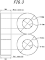
- test pieces as illustrated in FIG. 3 in which the diameter was 30 mm and the contact surface was a curved surface having a curvature radius of 15 mm, were prepared, and the test pieces were brought into contact with each other in the state illustrated in FIG. 3 under a contact stress of 1.2 GPa, a slip ratio of -20 % (rail material: 600 rpm, wheel material: 750 rpm), and a dry condition.
- the test lasted for 30 minutes, and the wear resistance was evaluated based on the change in weight before and after the test. The wear resistance was judged to be good when the change in weight was equal to or less than that of the reference steel.
- test pieces as illustrated in FIG. 4 in which the diameter was 30 mm and the contact surface was a curved surface having a curvature radius of 15 mm, were prepared, and the test pieces were brought into contact with each other in the state illustrated in FIG. 4 under a contact stress of 2.2 GPa, a slip ratio of -20 % (rail material: 600 rpm, wheel material: 750 rpm) and a lubricated condition.
- the test was stopped every 9000 rotations, the appearance of the test piece was observed, and the presence or absence of cracks on the contact surface was confirmed through the appearance observation.
- the test was ended when the occurrence of cracks was observed, and the RCF resistance was evaluated based on the total number of rotations at the end of the test.
- the RCF resistance was judged to be good when the total number of rotations increased by 10 % or more with respect to that of the reference steel.
- the hardness of the surface layer was measured with the following method.
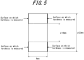
- both surfaces of the test piece were etched with a 3 % nital solution, and then the structure of the surface on which the hardness was to be measured, as illustrated in FIG. 5 , was observed to confirm the surface layer specified in the present disclosure. That is, in the structure observation, the pearlitic structure and the structure other than pearlite could be identified by color tone. Therefore, it was possible to distinguish the surface layer, which had the pearlitic structure and the structure other than pearlite, from portions other than the surface layer.
- the aforementioned etched test piece for hardness measurement was photographed by optical microscopy for 20 observation fields in the surface layer having a pearlitic structure and a structure other than pearlite at 100 magnifications.
- the structures other than the pearlitic structure were traced in the obtained micrograph, the fraction of the structure other than the pearlitic structure was calculated based on the following formula using the image interpretation software Image-Pro (NIPPON ROPPER K.K.), and the average value of the values of all the 20 observation fields was obtained.
- Fraction of structure other than pearlitic structure ⁇ (area of structure other than pearlitic structure)/(area of pearlitic structure + area of structure other than pearlitic structure) ⁇ ⁇ 100
- the test piece used in the RCF resistance evaluation test illustrated in FIG. 3 was cut as illustrated in FIG. 6 after the test, the cut surface was mirror-polished and then etched with a 3 % nital solution, and the structure of the surface on which the hardness was to be measured, as illustrated in FIG. 6 , was observed to confirm the surface layer specified in the present disclosure.
- the hardness of the pearlitic structure and the hardness of the structure other than the pearlitic structure were measured at 20 locations respectively with a micro Vickers hardness testing machine (HM-115, Vickers hardness) made by Akashi Corporation under a load of 0.98N. The maximum and minimum values of the measurement results are listed in Table 3.
- the test piece No. 1 which was a reference example, was a pearlitic rail steel in current use having a C content of 0.81 %.
- all the rails of Examples manufactured according to the present disclosure had good RCF resistance as compared with the rail of reference example No. 1, without deteriorating the wear resistance.
- the Comparative Examples that did not satisfy the conditions of the present disclosure were inferior in at least one of wear resistance and RCF resistance.
- Test pieces were prepared with the same procedure as in Example 1 except that steel having the chemical composition listed in Table 4 was used, and the hardness, wear resistance and RCF resistance were evaluated in the same manner as in Example 1.
- the heat treatment conditions are listed in Table 5, and the evaluation results are listed in Table 6.
Landscapes
- Chemical & Material Sciences (AREA)
- Engineering & Computer Science (AREA)
- Mechanical Engineering (AREA)
- Materials Engineering (AREA)
- Organic Chemistry (AREA)
- Metallurgy (AREA)
- Physics & Mathematics (AREA)
- Thermal Sciences (AREA)
- Crystallography & Structural Chemistry (AREA)
- Structural Engineering (AREA)
- Civil Engineering (AREA)
- Architecture (AREA)
- Heat Treatment Of Articles (AREA)
- Heat Treatment Of Steel (AREA)
Abstract
Description
- This disclosure relates to a rail used under harsh high-axle load conditions, such as under a condition where a heavy freight car travels on a track with many sharp curves. The disclosure particularly relates to a rail having excellent wear resistance and rolling contact fatigue (RCF) resistance suitable for a long service life.
- In heavy haul railways mainly built to transport ore, the load applied to the axle of a freight car is much higher than that of passenger cars, and rails and wheels are used in increasingly harsh environments. Such a heavy haul railway, that is, a rail used in a railway for trains or freight cars having a heavy loading weight, is conventionally mainly made of steel having a pearlitic structure from the viewpoint of attaching importance to wear resistance and RCF resistance. In recent years, it has been required to further improve the wear resistance and the RCF resistance of the rail to increase the loading weight on a freight car and improve the transportation efficiency.
- Therefore, various studies have been conducted with the aim of further improving wear resistance and RCF resistance. For example,
JP 4805414 B JP 4938158 B -
- PTL 1:
JP 4805414 B - PTL 2:
JP 4938158 B - When a train passes through a newly-installed rail, the rail comes into contact with the worn wheels of the train. Therefore, depending on the contact state, a fatigue layer may be accumulated in the rail surface layer, cracks may occur on the rail surface in an early stage just after the installing of the rail, and shelling may occur on the rail surface layer as cracks propagate and connect together. As a result, the service life of the rail is reduced.
- Therefore, in an early stage just after the installing of the rail, the rail should fit to the wheels. As illustrated in
FIG. 1 , the early stage targets asurface layer 2 from a head surface of a rail 1 to a depth of at least 0.5 mm. The depth of 0.5 mm is a position separated from the head surface of the rail by 0.5 mm in the normal direction. When the structure of the surface layer is only a pearlitic structure, wear of the rail is reduced, yet a fatigue layer is accumulated and cracks (for example, head checks) occur. If the rail is still used even after occurrence of cracks, the cracks propagate and connect together and eventually lead to occurrence of shelling. Therefore, it is necessary to suppress cracks by other methods than utilizing pearlitic structure. - However, both of the techniques described in the
above PTLS 1 and 2 are techniques of improving the RCF resistance without deteriorating the wear resistance of a rail by specifying the chemical composition as well as the fraction of a pearlitic structure of the rail head and the hardness of the pearlitic structure, which do not take it into consideration to suppress occurrence of cracks in an early stage just after the installing of the rail. - That is, the techniques described in the
above PTLS 1 and 2 specify the fraction of a pearlitic structure and the hardness of the pearlitic structure. However, wear resistance and RCF resistance are not simply determined by the hardness of a pearlitic structure, and the influence of structures other than the pearlitic structure should also be taken into consideration. The RCF resistance cannot be sufficiently improved by specifying the fraction of a pearlitic structure and the hardness of pearlite within that range. - It could thus be helpful to provide a way of improving the RCF resistance without deteriorating the wear resistance of a rail.
- As a result of studies to solve the above problem, we discovered that the RCF resistance can be improved without deteriorating the wear resistance of a rail by, in addition to specifying the hardness of a pearlitic structure in a surface layer of the rail, including a structure having specified hardness other than the pearlitic structure in the surface layer of the rail, and completed the present disclosure.
- The present disclosure is based on the aforementioned discoveries. We thus provide the following.
- 1. A rail comprising a metallic structure including a pearlitic structure and a structure other than the pearlitic structure in a surface layer from a surface of a rail head to a depth of at least 0.5 mm, wherein
the pearlitic structure has Vickers hardness of 420 HV or more and 520 HV or less, and the structure other than the pearlitic structure has Vickers hardness of 350 HV or more and 420 HV or less. - 2. The rail according to 1., comprising a chemical composition containing (consisting of), in mass%:
- C: 0.60 % to 1.20 %,
- Si: 0.10 % to 1.50 %,
- Mn: 0.10 % to 1.50 %,
- P: 0.025 % or less,
- S: 0.010 % or less, and
- Cr: 0.10 % to 1.50 %,
- the balance being Fe and inevitable impurities.
- 3. The rail according to 2., wherein the chemical composition further contains, in mass%, at least one selected from the group consisting of:
- V: 0.30 % or less,
- Cu: 1.0 % or less,
- Ni: 1.0 % or less,
- Nb: 0.05 % or less,
- Mo: 0.5 % or less,
- Al: 0.07 % or less,
- W: 1.0 % or less,
- Sb: 0.1 % or less,
- Sn: 0.1 % or less,
- B: 0.005 % or less, and
- Ti: 0.05 % or less.
- 4. The rail according to any one of 1. to 3., wherein an area fraction of the structure other than the pearlitic structure in the surface layer is more than 3 %.
- According to the present disclosure, it is possible to provide a rail which is excellent in wear resistance and RCF resistance and can be suitably used even in high-axle load railways.
- In the accompanying drawings:
-
FIG. 1 is a schematic view of the rail; -
FIG. 2 is a schematic view of a test piece to be subjected to heat treatment; -
FIG. 3 schematically illustrates a test piece for wear resistance evaluation and the test procedure; -
FIG. 4 schematically illustrates a test piece for RCF resistance evaluation and the test procedure; -
FIG. 5 illustrates a surface on which the hardness is measured of the test piece used in the wear resistance evaluation; and -
FIG. 6 illustrates a surface on which the hardness is measured of the test piece used in the RCF resistance evaluation. - The following describes the rail of the present disclosure in detail. It is important for the rail of the present disclosure to have a metallic structure including a pearlitic structure and a structure other than the pearlitic structure in a surface layer from a surface of a rail head to a depth of at least 0.5 mm, where the pearlitic structure has Vickers hardness of 420 HV or more and 520 HV or less, and the structure other than the pearlitic structure has Vickers hardness of 350 HV or more and 420 HV or less.
- To improve the fitting of the rail to wheels to avoid the occurrence of cracks in an early stage just after the installing of the rail, it is necessary to improve the fitting of the surface layer to wheels, where the surface layer is a region to a depth of at least 0.5 mm.
- As used herein, fitting to wheels means that the shape of the newly-installed rail follows close to the shape of the wheels passing on the rail. If only the hardness of the pearlitic structure is increased to ensure wear resistance as in the past, a fatigue layer is accumulated in the rail surface layer before the rail obtains a shape close to the abovementioned wheel shape, and cracks such as head checks or gauge corner shelling are likely to occur. As a result, the RCF resistance is deteriorated. Therefore, by mixing another structure that is less wear resistant than the pearlitic structure, the surface layer of the rail wears out to fit the rail to the wheels, and the RCF resistance is ensured by the wearing. However, even in the case of having a structure other than pearlite, if the hardness is too low, the wear resistance is rather deteriorated. On the other hand, if the hardness is too high, the progress of wearing is slowed down, which, on the contrary, tends to deteriorate the RCF resistance. Therefore, it is necessary to control not only the structure (microstructure) but also the hardness of the structure.
- That is, when the surface layer in which the hardness of the structure is controlled is shallower than a depth of 0.5 mm from the head surface of the rail, the fitting to the wheels cannot be ensured. Note that the surface layer in which the hardness of the structure is controlled does not have to be very deep. From the viewpoint of fitting the rail to the shape of the wheels, it is enough to have the microstructure and the hardness in a region to a depth of 3 mm satisfy the conditions of the present disclosure. From the viewp oint of the wear resistance of the rail, it is preferable to suppress the surface layer in which the hardness of the structure is controlled to a depth range of 3 mm or less.
- The reason why the structure of the surface layer includes a pearlitic structure and a structure other than the pearlitic structure is that, in the case of a single-phase structure of pearlite, although the wear resistance is good when the surface layer is in contact with the wheels, the stress is not dispersed when the rail is in contact with the wheels and a layer in which fatigue is accumulated is formed in the surface layer, and cracks are likely to occur in an early stage just after the installing of the rail. That is, by including a structure other than the pearlitic structure, stress can be dispersed when the rail is in contact with the wheels and the accumulation of fatigue is suppressed. As a result, the occurrence of cracks can be prevented.
- The rail of the present disclosure has a surface layer having a metallic structure including a pearlitic structure and a structure other than the pearlitic structure from a surface of the rail head to a depth of at least 0.5 mm. In the surface layer, the area fraction of the structure other than the pearlitic structure is preferably more than 3 %. When the area fraction of the structure is 3 % or less, the fraction of pearlite increases, the wear resistance is ensured, a fatigue layer is accumulated in the rail surface layer before the rail fits to a shape close to the abovementioned shape, cracks such as head checks are likely to occur. As a result, the RCF resistance is likely to be deteriorated. Therefore, the area fraction of the structure other than the pearlitic structure is preferably more than 3 %.
- Because the pearlitic structure and the structure other than the pearlitic structure can be identified by color tone, they can be identified through structure observation, for example. In addition, the boundary between the surface layer portion and other portions of the rail can also be determined through the structure observation. Further, the area fractions of the pearlitic structure and the structure other than the pearlitic structure in the surface layer can be obtained by calculating the respective areas of the pearlitic structure and the structure other than the pearlitic structure from the result of the determination.
- Further, the reasons for limiting the hardness of the pearlitic structure to 420 HV or more and 520 HV or less and limiting the hardness of the structure other than the pearlitic structure to 350 HV or more and 420 HV or less are as follows. When the hardness of the pearlitic structure is less than 420 HV and/or the hardness of the structure other than the pearlitic structure is less than 350 HV, it is difficult to ensure the wear resistance of the rail. On the other hand, when the hardness of the pearlitic structure exceeds 520 HV and/or the hardness of the structure other than the pearlitic structure exceeds 420 HV, the wear resistance can be ensured, yet on the other hand, the stress dispersion is insufficient and cracks are likely to occur in the rail. Therefore, the hardness of the pearlitic structure is 420 HV or more and preferably 425 HV or more, and the hardness of the pearlitic structure is 520 HV or less and preferably 515 HV or less. Further, the hardness of the structure other than the pearlitic structure is 350 HV or more and preferably 355 HV or more, and the hardness of the structure other than the pearlitic structure is 420 HV or less and preferably 419 HV or less.
- The hardness of each structure can be measured, for example, according to the following method. That is, as described above, the pearlitic structure and the structure other than pearlite are identified through the structure observation, and then the hardness can be measured in the respective regions of the specified pearlitic structure and the structure other than pearlite.
- As used herein, the structure other than the pearlitic structure may be any of ferrite, bainite, martensite, and tempered martensite. From the viewpoint of ensuring RCF resistance, bainite is preferable. Further, the structure of portions other than the surface layer of the rail, that is, the structure in a region deeper than the surface layer, which is a region from the head surface of the rail until a depth of 0.5 mm up to a maximum depth of 3 mm, is preferably a pearlitic structure.
- As described above, the rail of the present disclosure improves the RCF resistance without deteriorating the wear resistance by appropriately specifying the respective hardness of the pearlitic structure and the structure other than the pearlitic structure in the surface layer. The chemical composition is not particularly limited as long as it is a chemical composition capable of obtaining a pearlitic structure. The following chemical composition is suitable for a rail used under high-axle load conditions.
- Next, the reasons for limiting the content of each component of the preferred chemical composition of the rail of the present disclosure will be explained. Note that "%" indicating the content of each component is "mass%", unless otherwise stated.
- C is an element having the effect of forming cementite in the pearlitic structure to improve the hardness. Therefore, it is necessary to add C to ensure the wear resistance and the RCF resistance of the rail, and the hardness improves as the C content increases. That is, when the C content is less than 0.60 %, the hardness decreases. As a result, the wear resistance of the rail is likely to be deteriorated. Therefore, the C content is preferably 0.60 % or more and more preferably 0.62 % or more. On the other hand, when the C content exceeds 1.00 %, the hardness of the rail increases. As a result, the wear resistance is improved, yet a fatigue layer is accumulated and the RCF resistance of the rail is deteriorated. Therefore, the C content is preferably 1.00 % or less and more preferably 0.95 % or less.
- Si is an element having the effect as a deoxidation agent. In addition, Si has the effect of improving the hardness of the rail through the solution strengthening to ferrite in pearlite. Therefore, the Si content is preferably 0.10 % or more and more preferably 0.15 % or more. On the other hand, when the Si content exceeds 1.5 %, a large amount of oxide inclusions is formed since Si strongly binds with oxygen. As a result, the RCF resistance is deteriorated. Therefore, the Si content is preferably 1.50 % or less.
- Mn is an element that improves the hardness of the rail by lowering the transformation temperature and reducing the lamellar spacing. However, when the Mn content is less than 0.10 %, the effect is insufficient. Therefore, the Mn content is preferably 0.10 % or more and more preferably 0.15 % or more. On the other hand, when the Mn content exceeds 1.50 %, micro segregation of the steel with a high Mn concentration likely to cause formation of a martensitic structure. As a result, the RCF resistance is deteriorated. Therefore, the Mn content is preferably 1.50 % or less.
- When the P content exceeds 0.025 %, the ductility of the rail decreases. Therefore, the P content is preferably 0.025 % or less. On the other hand, the lower limit of the P content is not particularly limited and may be 0 %, yet it is usually more than 0 % in industrial terms. Note that excessive reduction of the P content causes an increase in refining cost. Therefore, from the viewpoint of economic efficiency, the P content is preferably 0.001 % or more.
- S is mainly present in steel in the form of A type (sulfide) inclusions. When the S content exceeds 0.010 %, the amount of the inclusions is significantly increased, and coarse inclusions are formed. As a result, the RCF resistance is deteriorated. Therefore, the S content is preferably 0.010 % or less and more preferably 0.009 % or less. On the other hand, the lower limit of the S content is not particularly limited and may be 0 %, yet it is usually more than 0 % in industrial terms. Note that when the S content is less than 0.0005 %, the refining cost increases. Therefore, from the viewpoint of economic efficiency, the S content is preferably 0.0005 % or more.
- Cr is an element that has the effect of improving the hardness of the rail through the solution strengthening to cementite in pearlite. To obtain this effect, the Cr content is preferably 0.10 % or more and more preferably 0.15 % or more. On the other hand, when the Cr content exceeds 1.50 %, a martensitic structure is formed because of the solution strengthening of Cr. As a result, the RCF resistance is deteriorated. Therefore, the Cr content is preferably 1.50 % or less.
- The steel material of the rail of the present disclosure preferably contains the above components, and the balance is preferably Fe and inevitable impurities. Further, the following elements may be added as necessary within a range not substantially affecting the action and effect of the present disclosure.
- That is, it is possible to further contain at least one selected from the group consisting of the following elements as necessary:
- V: 0.30 % or less,
- Cu: 1.0 % or less,
- Ni: 1.0 % or less,
- Nb: 0.05 % or less,
- Mo: 0.5 % or less,
- Al: 0.07 % or less,
- W: 1.0 % or less,
- Sb: 0.1 % or less,
- Sn: 0.1 % or less,
- B: 0.005 % or less, and
- Ti: 0.05 % or less.
- V is an element that precipitates as carbonitrides during and after rolling and has the effect of improving the hardness of the rail through precipitation strengthening. Therefore, it is preferable to add V in an amount of 0.001 % or more. On the other hand, when the V content exceeds 0.30 %, a large amount of coarse carbonitrides precipitates, which causes deterioration in RCF resistance. Therefore, in the case of adding V, the V content is preferably 0.30 % or less.
- Cu, like Cr, is an element having the effect of improving the hardness of the rail through solution strengthening. Therefore, it is preferable to add Cu in an amount of 0.001 % or more. On the other hand, when the Cu content exceeds 1.0 %, Cu cracking occurs. Therefore, in the case of adding Cu, the Cu content is preferably 1.0 % or less.
- Ni has the effect of improving the hardness of the rail without deteriorating the ductility. Therefore, it is preferable to add Ni in an amount of 0.001 % or more. Further, since Cu cracking can be suppressed by adding Ni in combination with Cu, it is desirable to also add Ni in the case of adding Cu. On the other hand, when the Ni content exceeds 1.0 %, the quench hardenability is increased and martensite is formed, resulting in deterioration in RCF resistance. Therefore, in the case of adding Ni, the Ni content is preferably 1.0 % or less.
- Nb precipitates as carbonitrides during and after rolling to improve the hardness of the rail. Therefore, it is preferable to add Nb in an amount of 0.001 % or more. On the other hand, when the Nb content exceeds 0.05 %, a large amount of coarse carbonitrides precipitates, which decreases the ductility. Therefore, in the case of adding Nb, the Nb content is preferably 0.05 % or less.
- Mo precipitates as carbides during and after rolling and improves the hardness of the rail through precipitation strengthening. Therefore, it is preferable to add Mo in an amount of 0.001 % or more. On the other hand, when the Mo content exceeds 0.5 %, martensite is formed, resulting in deterioration in RCF resistance. Therefore, in the case of adding Mo, the Mo content is preferably 0.5 % or less.
- Al is an element added as a deoxidation agent. Therefore, it is preferable to add Al in an amount of 0.001 % or more. On the other hand, when the Al content exceeds 0.07 %, a large amount of oxide inclusions is formed since Al strongly binds with oxygen. As a result, the RCF resistance is deteriorated. Therefore, the Al content is preferably 0.07 % or less.
- W precipitates as carbides during and after rolling and improves the hardness of the rail through precipitation strengthening. Therefore, it is preferable to add W in an amount of 0.001 % or more. On the other hand, when the W content exceeds 1.0 %, martensite is formed, resulting in deterioration in RCF resistance. Therefore, in the case of adding W, the W content is preferably 1.0 % or less.
- Sb is an element which, when reheating a steel material of a rail in a heating furnace, prevents decarburization during the reheating, prevents a decrease in the amount of cementite in a pearlitic structure, and contributes to the improvement of hardness. Therefore, it is preferable to add Sb in an amount of 0.001 % or more. On the other hand, when Sb is added in an amount exceeding 0.1 %, the Sb concentrates at austenite grain boundaries during heating, and cracking occurs. Therefore, in the case of adding Sb, the Sb is preferably added in an amount of 0.1 % or less.
- Sb is an element which, when reheating a steel material of a rail in a heating furnace, prevents decarburization during the reheating, prevents a decrease in the amount of cementite in a pearlitic structure, and contributes to the improvement of hardness. Therefore, it is preferable to add Sn in an amount of 0.001 % or more. On the other hand, when Sn is added in an amount exceeding 0.1 %, the Sn concentrates at austenite grain boundaries during heating, and cracking occurs. Therefore, in the case of adding Sn, the Sn content is preferably 0.1 % or less.
- B precipitates as nitrides during and after rolling and improves the hardness of the rail through precipitation strengthening. Therefore, it is preferable to add B in an amount of 0.0001 % or more. However, when the B content exceeds 0.005 %, martensite is formed, resulting in deterioration in RCF resistance. Therefore, in the case of adding B, the B content is preferably 0.005 % or less.
- Ti precipitates as carbides, nitrides or carbonitrides during and after rolling and improves the hardness of the rail through precipitation strengthening. Therefore, it is preferable to add Ti in an amount of 0.001 % or more. However, when the Ti content exceeds 0.05 %, coarse carbides, nitrides or carbonitrides are formed, resulting in deterioration in RCF resistance. Therefore, in the case of adding Ti, the Ti content is preferably 0.05 % or less.
- The rail of the present disclosure can be manufactured by performing hot rolling and then cooling according to a usual method. For example, it is preferable to apply the following manufacturing conditions. That is, it is preferable to reheat a continuously-cast bloom at a reheating temperature of 1000 °C or higher and 1350 °C or lower for 3600 seconds or longer, and subject the bloom to hot rolling and then cooling. In the cooling, it is preferable to perform cooling at a cooling rate of 2 °C/s or higher and 10 °C/s or lower from a temperature region of 700 °C or higher (first cooling treatment), hold the bloom at a temperature region of 460 °C or higher and 600 °C or lower for 5 seconds or longer and 60 seconds or shorter (first holding) during the cooling, then perform cooling at a cooling rate of 1 °C/s or lower and 7 °C/s or higher (second cooling treatment), and hold the bloom at a temperature region of 350 °C or higher and 450 °C or lower for 60 seconds or longer (second holding). The cooling method thereafter is not particularly limited, and the bloom may be allowed to be naturally cooled, for example.
- The cooling treatment will be described with a specific example. For example, in the case where a 136-pound rail defined by AREMA (American Railway Engineering and Maintenance-of-Way Association) is manufactured by performing smelting to obtain a steel having the chemical composition of A2 steel listed in Table 1 described later, subjecting the steel to continuous casting to obtain a continuous-cast steel, and subjecting the continuous-cast steel to hot rolling and cooling, the cooling conditions in this case are as follows.
- Cooling start temperature: 750 °C
- First cooling rate: 5 °C/s
- First holding temperature: 550 °C
- First holding time: 20 seconds
- Second cooling rate: 2 °C/s
- Second holding temperature: 430 °C/s
- Second holding time: 300 seconds
- Microstructure observation and hardness measurement of the rail thus manufactured were performed with the method described below. It was confirmed that, the region from the surface of the rail head to a depth of 1 mm had a pearlitic structure and a structure other than the pearlitic structure (in this case, it was bainitic structure), and the fraction of the structure other than the pearlitic structure was 5 %. It was also confirmed that the hardness of the pearlitic structure was HV450 at the maximum and HV434 at the minimum, and the hardness of the structure other than the pearlitic structure was HV380 at the maximum and HV360 at the minimum. That is, the rail of the present disclosure can be manufactured according to the above manufacturing conditions in the actual rail manufacture. Although it is preferable to manufacture rails with the above manufacturing process and actually install the rails for evaluation in the following Examples, it takes too much time. Therefore, in the present disclosure, the rail performance is evaluated by changing the microstructure and the hardness in a laboratory.
- It takes too much time to manufacture rails and then install the rails to evaluate their properties. Therefore, in the present example, a rail steel material was manufactured with the following method, and a test piece was obtained from the rail steel material and subjected to evaluation.
- That is, 100 kg of rail steel having the chemical composition listed in Table 1 was refined by vacuum melting and then cast, followed by hot-rolling to 80 mm thickness. Further, the rolled material was cut into a length of 150 mm, then heated to 1000 °C to 1300 °C, hot-rolled to a final plate thickness of 12 mm, and then allowed to be cooled. A disk test piece having a diameter of 32 mm and a thickness of 5 mm as illustrated in
FIG. 2 was obtained from the obtained rail steel material. Next, the obtained disk test piece was subjected to heat treatment according to the conditions listed in Table 2. That is, first, the disk test piece was heated and then naturally cooled, and from a predetermined cooling start temperature, the test piece was cooled at a first cooling rate higher than the rate of natural cooling. Next, the cooling was stopped when the test piece reached a predetermined first holding temperature, and the test piece was held at the predetermined first holding temperature just for predetermined holding time. - After being held at the first holding temperature, the test piece was cooled at a second cooling rate higher than the rate of natural cooling. The cooling was stopped when the test piece reached a predetermined second holding temperature, and the test piece was held at the predetermined second holding temperature just for predetermined holding time. After being held at the second holding temperature, the test piece was naturally cooled. After the heat treatment, it was machined to the test piece illustrated in
FIG. 3 . - Because the test piece of the present example was manufactured in a laboratory, the size of the manufactured steel material was different from that of the steel material manufactured with an actual manufacturing facility, and the heat capacity of the steel material was also greatly different from that of the steel material manufactured with an actual manufacturing facility. Therefore, regardless of whether or not the conditions of the present example corresponded to the aforementioned preferable manufacturing conditions for an actual manufacturing facility, the present example appropriately adjusted the heat treatment conditions to manufacture test materials having various microstructures and hardness, and mainly the structure of the surface layer of the test materials were compared and evaluated.
- For the test piece thus obtained, the region corresponding to the surface layer was specified as described later, and the hardness of each structure in that region was measured as described later. At the same time, the wear resistance and the RCF resistance of each test piece was evaluated with the test methods described later. The evaluation results are listed in Table 3.
- As described above, it is most desirable to actually install and use a rail to evaluate its wear resistance and RCF resistance, yet the test takes too much time. Therefore, the present disclosure used a twin disc type rolling contact test machine, with which the wear resistance and the RCF resistance could be evaluated in a short period of time, and performed a comparing test, in which the actual contacting conditions between a rail and a wheel were simulated, to evaluate the wear resistance and the RCF resistance. Note that the wheel material used in both wear resistance and RCF resistance tests was a wheel having a pearlitic structure and a hardness of 370 HV.
- With respect to the wear resistance, test pieces as illustrated in
FIG. 3 , in which the diameter was 30 mm and the contact surface was a curved surface having a curvature radius of 15 mm, were prepared, and the test pieces were brought into contact with each other in the state illustrated inFIG. 3 under a contact stress of 1.2 GPa, a slip ratio of -20 % (rail material: 600 rpm, wheel material: 750 rpm), and a dry condition. The test lasted for 30 minutes, and the wear resistance was evaluated based on the change in weight before and after the test. The wear resistance was judged to be good when the change in weight was equal to or less than that of the reference steel. - With respect to the RCF resistance, test pieces as illustrated in
FIG. 4 , in which the diameter was 30 mm and the contact surface was a curved surface having a curvature radius of 15 mm, were prepared, and the test pieces were brought into contact with each other in the state illustrated inFIG. 4 under a contact stress of 2.2 GPa, a slip ratio of -20 % (rail material: 600 rpm, wheel material: 750 rpm) and a lubricated condition. The test was stopped every 9000 rotations, the appearance of the test piece was observed, and the presence or absence of cracks on the contact surface was confirmed through the appearance observation. The test was ended when the occurrence of cracks was observed, and the RCF resistance was evaluated based on the total number of rotations at the end of the test. The RCF resistance was judged to be good when the total number of rotations increased by 10 % or more with respect to that of the reference steel. - The hardness of the surface layer was measured with the following method.
- Before subjecting the test piece used in the wear resistance evaluation test illustrated in
FIG. 3 to the wear resistance evaluation test, both surfaces of the test piece were etched with a 3 % nital solution, and then the structure of the surface on which the hardness was to be measured, as illustrated inFIG. 5 , was observed to confirm the surface layer specified in the present disclosure. That is, in the structure observation, the pearlitic structure and the structure other than pearlite could be identified by color tone. Therefore, it was possible to distinguish the surface layer, which had the pearlitic structure and the structure other than pearlite, from portions other than the surface layer. Next, the hardness of the pearlitic structure and the hardness of the structure other than the pearlitic structure were measured at 20 locations respectively with a micro Vickers hardness testing machine (HM-115, Vickers hardness) made by Akashi Corporation under a load of 0.98 N. The maximum and minimum values of the measurement results are listed in Table 3. - The aforementioned etched test piece for hardness measurement was photographed by optical microscopy for 20 observation fields in the surface layer having a pearlitic structure and a structure other than pearlite at 100 magnifications. Next, the structures other than the pearlitic structure were traced in the obtained micrograph, the fraction of the structure other than the pearlitic structure was calculated based on the following formula using the image interpretation software Image-Pro (NIPPON ROPPER K.K.), and the average value of the values of all the 20 observation fields was obtained. Fraction of structure other than pearlitic structure = {(area of structure other than pearlitic structure)/(area of pearlitic structure + area of structure other than pearlitic structure)} × 100
- Further, the test piece used in the RCF resistance evaluation test illustrated in
FIG. 3 was cut as illustrated inFIG. 6 after the test, the cut surface was mirror-polished and then etched with a 3 % nital solution, and the structure of the surface on which the hardness was to be measured, as illustrated inFIG. 6 , was observed to confirm the surface layer specified in the present disclosure. Next, the hardness of the pearlitic structure and the hardness of the structure other than the pearlitic structure were measured at 20 locations respectively with a micro Vickers hardness testing machine (HM-115, Vickers hardness) made by Akashi Corporation under a load of 0.98N. The maximum and minimum values of the measurement results are listed in Table 3.Table 1 Steel sample ID Chemical composition (mass%)* Remarks C Si Mn P S Cr A1 0.81 0.28 1.22 0.009 0.005 0.23 Reference steel A2 0.84 0.62 0.62 0.011 0.004 0.69 - * The balance is Fe and inevitable impurities. Table 2 Heating process Cooling process Test piece No. Steel sample ID Heating temperature (°C) Heating holding time (second) Cooling start temperature (°C) First cooling rate (°C/s) First holding temperature (°C) First holding time (second) Second cooling rate (°C/s) Second holding temperature (°C) Second holding time (second) 1 A1 1250 600 740 5 550 60 - - - 2 A2 1250 600 730 6 550 45 6 450 300 3 A2 1250 600 770 5 525 45 5 400 350 4 A2 1250 600 750 7 600 10 3 350 300 5 A2 1250 600 710 3 600 10 4 400 250 6 A2 1250 600 720 6 575 30 4 450 250 7 A2 1250 600 730 4 525 30 7 400 350 8 A2 1250 600 730 5 550 60 3 425 120 9 A2 1250 600 750 7 525 60 4 425 350 10 A2 1250 600 740 10 500 3 3 450 300 11 A2 1250 600 750 6 675 5 3 450 450 12 A2 1250 600 750 6 550 45 1 475 200 13 A2 1250 600 740 5 550 40 7 325 400 14 A2 1250 600 740 6 650 5 5 400 350 15 A2 1250 600 730 8 600 20 4 450 300 16 A2 1250 600 740 8 550 45 3 450 250 17 A2 1250 600 700 5 600 40 4 350 300 18 A2 1250 600 715 7 600 25 5 450 150 Table 3 Surface layer Structure of portions other than surface layer Test piece No. Steel sample ID Range of depth from surface (mm) Hardness of pearlitic structure: maximum value (HV) Hardness of pearlitic structure: minimum value (HV) Hardness of structure other than pearlitic structure: maximum value (HV) Hardness of structure other than pearlitic structure: minimum value (HV) Fraction of structure other than pearlitic structure (%) Structure other than pearlitic structure Amount of wear (g/0.5h) Number of rotations until occurrence of cracks Remarks 1 A1 0.0 402 390 - - 0.0 - Pearlite 0.31 144000 Reference Example 2 A2 1.0 519 472 387 359 3.7 Bainite Pearlite 0.26 360000 Example 3 A2 3.0 486 435 401 388 5.8 Bainite Pearlite 0.27 306000 Example 4 A2 0.5 429 420 420 400 7.9 Bainite Pearlite 0.30 198000 Example 5 A2 0.5 431 420 403 358 3.8 Bainite Pearlite 0.31 234000 Example 6 A2 1.3 438 423 366 351 3.9 Bainite Pearlite 0.31 252000 Example 7 A2 2.0 483 445 409 388 12.1 Bainite Pearlite 0.28 324000 Example 8 A2 0.9 452 432 375 350 5.4 Bainite Pearlite 0.29 252000 Example 9 A2 2.8 482 455 388 359 7.9 Bainite Pearlite 0.28 342000 Example 10 A2 3.0 525 477 354 350 12.5 Bainite Pearlite 0.25 126000 Comparative Example 11 A2 0.5 423 415 358 350 3.6 Bainite Pearlite 0.36 216000 Comparative Example 12 A2 1.1 465 439 356 345 3.6 Bainite Pearlite 0.34 270000 Comparative Example 13 A2 1.2 469 438 424 395 8.3 Bainite Pearlite 0.30 144000 Comparative Example 14 A2 0.2 438 422 366 359 2.9 Bainite Pearlite 0.30 144000 Comparative Example 15 A2 0.5 433 428 400 359 3.0 Bainite Pearlite 0.30 162000 Example 16 A2 0.7 449 442 366 353 3.2 Bainite Pearlite 0.30 180000 Example 17 A2 0.5 432 429 400 360 3.1 Bainite + tempered martens ite Pearlite 0.29 180000 Example 18 A2 0.5 433 422 364 359 2.7 Bainite Pearlite 0.26 144000 Example - In the above example, the test piece No. 1, which was a reference example, was a pearlitic rail steel in current use having a C content of 0.81 %. As can be understood from the results listed in Table 3, all the rails of Examples manufactured according to the present disclosure had good RCF resistance as compared with the rail of reference example No. 1, without deteriorating the wear resistance. On the other hand, the Comparative Examples that did not satisfy the conditions of the present disclosure were inferior in at least one of wear resistance and RCF resistance.
- Test pieces were prepared with the same procedure as in Example 1 except that steel having the chemical composition listed in Table 4 was used, and the hardness, wear resistance and RCF resistance were evaluated in the same manner as in Example 1. The heat treatment conditions are listed in Table 5, and the evaluation results are listed in Table 6.
Table 4 Steel sample ID Chemical composition (mass%)* Remarks C Si Mn P S Cr Cu Ni Mo V Nb Al w B Ti Sn Sb A1 0.81 0.28 1.22 0.009 0.005 0.23 - - - - - - - - - - - Reference steel B1 0.83 1.50 0.48 0.014 0.007 0.26 - - - - - - - - - - - Conforming steel B2 0.83 0.25 0.85 0.005 0.007 0.61 - - - - - - - - - - - Conforming steel B3 0.70 0.42 0.40 0.003 0.006 1.50 - - - - - - - - - - - Conforming steel B4 1.00 0.88 0.46 0.016 0.005 0.79 - - - - - - - - - - - Conforming steel B5 0.83 0.25 0.62 0.003 0.006 0.26 - - - - - - - - - - - Conforming steel B6 0.83 0.23 1.21 0.005 0.007 0.21 - - - - - - - - - - - Conforming steel B7 0.60 0.69 0.56 0.015 0.007 1.00 - - - - - - - - - - - Conforming steel B8 0.71 1.16 1.34 0.016 0.004 0.88 - - - - - - - - - - - Conforming steel B9 0.84 1.06 0.83 0.019 0.006 0.05 - - - - - - - - - - 0.03 Conforming steel B10 0.85 0.48 0.71 0.016 0.004 0.32 - - - - - - - - - 0.02 - Conforming steel B11 0.84 0.55 0.55 0.014 0.005 0.79 - - - 0.05 - - - - - - - Conforming steel B12 0.84 0.51 0.61 0.008 0.004 0.74 - - - 0.15 - - - - - - - Conforming steel B13 0.84 0.25 1.10 0.006 0.005 0.25 - - - - 0.04 - - - - - - Conforming steel B14 0.84 0.35 1.05 0.003 0.004 0.29 - - 0.30 - - - - - - - - Conforming steel B15 0.84 0.55 0.55 0.011 0.005 0.62 0.30 0.50 - - - - - - - - - Conforming steel B16 0.84 0.25 1.21 0.004 0.005 0.29 - - - - - 0.07 0.60 - - - - Conforming steel B17 0.84 0.95 0.54 0.005 0.005 0.44 - - - - - - - 0.003 0.05 - - Conforming steel B18 0.84 0.95 0.56 0.011 0.005 0.80 - - - 0.05 - - - - - - - Conforming steel * The balance is Fe and inevitable impurities. Table 5 Heating process Cooling process Test piece No. Steel sample ID Heating temperature (°C) Heating holding time (second) Cooling start temperature (°C) First cooling rate (°C/s) First holding temperature (°C) First holding time (second) Second cooling rate (°C/s) Second holding temperature (°C) Second holding time (second) 1 A1 1250 600 740 5 550 60 - - - 2 B1 1250 600 730 7 520 45 5 450 300 3 B2 1250 600 750 7 520 45 5 400 400 4 B3 1250 600 710 8 520 45 6 425 375 5 B4 1250 600 710 7 520 45 6 425 375 6 B5 1250 600 720 6 520 45 5 400 400 7 B6 1250 600 730 6 520 45 5 450 300 8 B7 1250 600 720 6 520 45 5 450 300 9 B8 1250 600 740 8 520 45 7 425 350 10 B9 1250 600 750 7 520 45 7 425 350 11 B10 1250 600 730 7 520 45 6 425 350 12 B11 1250 600 720 7 520 45 3 450 300 13 B12 1250 600 750 8 520 45 4 460 300 14 B13 1250 600 760 8 520 45 4 425 350 15 B14 1250 600 800 5 520 45 5 450 300 16 B15 1250 600 790 6 520 45 5 460 300 17 B16 1250 600 740 6 520 45 5 460 300 18 B17 1250 600 770 6 520 45 4 440 300 19 B18 1250 600 780 5 520 45 4 450 300 Table 6 Test piece No. Steel sample ID Surface layer Structure of portions other than surface layer Amount of wear (g/0.5h) Number of rotations until occurrence of cracks Remarks Range of depth from surface (mm) Hardness of pearlitic structure: maximum value (HV) Hardness of pearlitic structure: minimum value (HV) Hardness of structure other than pearlitic structure: maximum value (HV) Hardness of structure other than pearlitic structure: minimum value (HV) Fraction of structure other than pearlitic structure (%) Structure other than pearlitic structure 1 A1 0.0 402 390 - - 0.0 - Pearlite 0.31 144000 Reference Example 2 B1 0.5 520 488 382 366 3.5 Bainite Pearlite 0.27 360000 Example 3 B2 0.8 435 420 419 392 4.1 Bainite Pearlite 0.29 234000 Example 4 B3 0.7 429 421 408 388 4.2 Bainite Pearlite 0.29 252000 Example 5 B4 1.1 518 487 401 376 4.1 Bainite Pearlite 0.26 342000 Example 6 B5 0.5 438 421 411 377 4.2 Bainite Pearlite 0.29 252000 Example 7 B6 0.7 442 429 364 350 4.1 Bainite Pearlite 0.30 288000 Example 8 B7 0.5 432 420 389 367 4.2 Bainite Pearlite 0.31 270000 Example 9 B8 2.5 434 422 388 366 3.9 Bainite Pearlite 0.30 279000 Example 10 B9 0.6 449 432 367 354 3.8 Bainite Pearlite 0.30 288000 Example 11 B10 0.8 441 429 371 364 3.9 Bainite Pearlite 0.30 279000 Example 12 B11 1.0 456 448 358 350 4.0 Bainite Pearlite 0.29 324000 Example 13 B12 1.2 462 442 357 350 4.1 Bainite Pearlite 0.29 333000 Example 14 B13 1.0 428 420 374 366 4.2 Bainite Pearlite 0.31 270000 Example 15 B14 0.9 439 428 365 354 4.1 Bainite Pearlite 0.30 288000 Example 16 B15 0.9 457 443 362 356 3.7 Bainite Pearlite 0.29 297000 Example 17 B16 1.0 463 443 362 351 4.0 Bainite Pearlite 0.29 306000 Example 18 B17 0.8 476 448 377 368 4.1 Bainite Pearlite 0.29 315000 Example 19 B18 1.8 489 465 392 377 4.2 Bainite Pearlite 0.27 306000 Example - As can be understood from the results listed in Table 6, all the rails satisfying the conditions of the present disclosure had improved RCF resistance as compared with the rail of the test piece No. 1, which was the reference example, without deteriorating the wear resistance.
Claims (4)
- A rail comprising a metallic structure including a pearlitic structure and a structure other than the pearlitic structure in a surface layer from a surface of a rail head to a depth of at least 0.5 mm, wherein
the pearlitic structure has Vickers hardness of 420 HV or more and 520 HV or less, and the structure other than the pearlitic structure has Vickers hardness of 350 HV or more and 420 HV or less. - The rail according to claim 1, comprising a chemical composition containing, in mass%:C: 0.60 % to 1.20 %,Si: 0.10 % to 1.50 %,Mn: 0.10 % to 1.50 %,P: 0.025 % or less,S: 0.010 % or less, andCr: 0.10 % to 1.50 %,the balance being Fe and inevitable impurities.
- The rail according to claim 2, wherein the chemical composition further contains, in mass%, at least one selected from the group consisting of:V: 0.30 % or less,Cu: 1.0 % or less,Ni: 1.0 % or less,Nb: 0.05 % or less,Mo: 0.5 % or less,Al: 0.07 % or less,W: 1.0 % or less,Sb: 0.1 % or less,Sn: 0.1 % or less,B: 0.005 % or less, andTi: 0.05 % or less.
- The rail according to any one of claims 1 to 3, wherein an area fraction of the structure other than the pearlitic structure in the surface layer is more than 3 %.
Applications Claiming Priority (2)
| Application Number | Priority Date | Filing Date | Title |
|---|---|---|---|
| JP2018068803 | 2018-03-30 | ||
| PCT/JP2019/012568 WO2019189015A1 (en) | 2018-03-30 | 2019-03-25 | Rail |
Publications (2)
| Publication Number | Publication Date |
|---|---|
| EP3778955A1 true EP3778955A1 (en) | 2021-02-17 |
| EP3778955A4 EP3778955A4 (en) | 2021-05-05 |
Family
ID=68059958
Family Applications (1)
| Application Number | Title | Priority Date | Filing Date |
|---|---|---|---|
| EP19775316.3A Pending EP3778955A4 (en) | 2018-03-30 | 2019-03-25 | Rail |
Country Status (7)
| Country | Link |
|---|---|
| US (1) | US11566307B2 (en) |
| EP (1) | EP3778955A4 (en) |
| JP (1) | JP6610844B1 (en) |
| CN (1) | CN111989416A (en) |
| AU (1) | AU2019242777B2 (en) |
| CA (1) | CA3095559C (en) |
| WO (1) | WO2019189015A1 (en) |
Families Citing this family (2)
| Publication number | Priority date | Publication date | Assignee | Title |
|---|---|---|---|---|
| WO2022106864A1 (en) * | 2020-11-17 | 2022-05-27 | Arcelormittal | Steel for rails and a method of manufacturing of a rail thereof |
| WO2026094371A1 (en) * | 2024-10-29 | 2026-05-07 | 日本製鉄株式会社 | Rail |
Family Cites Families (22)
| Publication number | Priority date | Publication date | Assignee | Title |
|---|---|---|---|---|
| DE1492461A1 (en) | 1964-11-30 | 1970-02-12 | American Sterilizer Co | Sterilization process |
| JPS54148124A (en) * | 1978-05-12 | 1979-11-20 | Nippon Steel Corp | Manufacture of high strength rall of excellent weldability |
| JP3513427B2 (en) | 1999-05-31 | 2004-03-31 | 新日本製鐵株式会社 | Pearlitic rail excellent in wear resistance and internal fatigue damage resistance, and method of manufacturing the same |
| JP2002363698A (en) * | 2001-06-07 | 2002-12-18 | Nippon Steel Corp | Rail with excellent rolling fatigue damage resistance and abrasion resistance and method of manufacturing the same |
| JP4272437B2 (en) | 2003-01-20 | 2009-06-03 | 新日本製鐵株式会社 | High carbon steel rail manufacturing method |
| EP2135966B1 (en) * | 2007-03-28 | 2017-05-03 | JFE Steel Corporation | Pearlite steel rail of high internal hardness type excellent in wear resistance and fatigue failure resistance and process for production of the same |
| JP5292875B2 (en) | 2007-10-10 | 2013-09-18 | Jfeスチール株式会社 | Internal high-hardness pearlitic steel rail with excellent wear resistance, fatigue damage resistance and delayed fracture resistance, and manufacturing method thereof |
| JP5282506B2 (en) * | 2008-09-25 | 2013-09-04 | Jfeスチール株式会社 | Internal high hardness type pearlitic steel rail with excellent wear resistance and fatigue damage resistance and method for manufacturing the same |
| CN102301023B (en) * | 2009-02-18 | 2013-07-10 | 新日铁住金株式会社 | Pearlitic rail with excellent wear resistance and toughness |
| WO2010150448A1 (en) | 2009-06-26 | 2010-12-29 | 新日本製鐵株式会社 | Pearlite–based high-carbon steel rail having excellent ductility and process for production thereof |
| CN102203311B (en) * | 2009-08-18 | 2013-07-24 | 新日铁住金株式会社 | Pearlite system rail |
| AU2011262876B2 (en) | 2010-06-07 | 2016-02-04 | Nippon Steel Corporation | Steel rail and method of manufacturing the same |
| AU2013253561B2 (en) * | 2012-04-23 | 2014-12-18 | Nippon Steel Corporation | Rail |
| BR112014031008B1 (en) * | 2012-06-14 | 2020-02-18 | Nippon Steel Corporation | RAIL RAIL AND ITS PRODUCTION METHODS |
| BR112015024651B1 (en) * | 2013-03-27 | 2019-10-08 | Jfe Steel Corporation | METHOD FOR MANUFACTURING A PERLITA RAIL |
| CA2936780C (en) | 2014-03-24 | 2018-10-02 | Jfe Steel Corporation | Rail and method for manufacturing same |
| CN103966520B (en) | 2014-05-08 | 2016-07-06 | 攀钢集团攀枝花钢铁研究院有限公司 | A kind of bainite rail containing trace carbon compound and production method thereof |
| CA2946548C (en) * | 2014-05-29 | 2018-11-20 | Nippon Steel & Sumitomo Metal Corporation | Rail and production method therefor |
| CN104561816B (en) | 2015-01-07 | 2016-08-31 | 攀钢集团攀枝花钢铁研究院有限公司 | The rail of a kind of high-strength, fatigue-resistant function admirable and production method thereof |
| CA2973858C (en) * | 2015-01-23 | 2019-09-03 | Nippon Steel & Sumitomo Metal Corporation | Rail |
| WO2016117689A1 (en) * | 2015-01-23 | 2016-07-28 | 新日鐵住金株式会社 | Rail |
| JP6459623B2 (en) * | 2015-02-25 | 2019-01-30 | 新日鐵住金株式会社 | Perlite steel rail |
-
2019
- 2019-03-25 JP JP2019536333A patent/JP6610844B1/en active Active
- 2019-03-25 EP EP19775316.3A patent/EP3778955A4/en active Pending
- 2019-03-25 CA CA3095559A patent/CA3095559C/en active Active
- 2019-03-25 WO PCT/JP2019/012568 patent/WO2019189015A1/en not_active Ceased
- 2019-03-25 CN CN201980022202.7A patent/CN111989416A/en active Pending
- 2019-03-25 AU AU2019242777A patent/AU2019242777B2/en active Active
- 2019-03-25 US US17/040,538 patent/US11566307B2/en active Active
Also Published As
| Publication number | Publication date |
|---|---|
| JP6610844B1 (en) | 2019-11-27 |
| WO2019189015A1 (en) | 2019-10-03 |
| CN111989416A (en) | 2020-11-24 |
| JPWO2019189015A1 (en) | 2020-04-30 |
| CA3095559C (en) | 2022-10-04 |
| BR112020019343A2 (en) | 2021-01-05 |
| AU2019242777A1 (en) | 2020-10-08 |
| EP3778955A4 (en) | 2021-05-05 |
| CA3095559A1 (en) | 2019-10-03 |
| US20210269901A1 (en) | 2021-09-02 |
| AU2019242777B2 (en) | 2021-09-23 |
| US11566307B2 (en) | 2023-01-31 |
Similar Documents
| Publication | Publication Date | Title |
|---|---|---|
| EP3124636B2 (en) | Rail and method for manufacturing same | |
| US20160194729A1 (en) | High-strength and highly fatigue-resistant steel rail and production method thereof | |
| US9534278B2 (en) | Rail | |
| EP3778961B1 (en) | Rail and method for manufacturing same | |
| JP5282506B2 (en) | Internal high hardness type pearlitic steel rail with excellent wear resistance and fatigue damage resistance and method for manufacturing the same | |
| EP3717142B1 (en) | Method for manufacturing a rail and corresponding rail | |
| JP6852761B2 (en) | Rails and their manufacturing methods | |
| US11566307B2 (en) | Rail | |
| US20200017943A1 (en) | Track part made of a hypereutectoid steel | |
| JP2000129397A (en) | Pearlitic rail with excellent wear resistance and ductility | |
| EP3778966A1 (en) | Rail and method for manufacturing same | |
| BR112020019343B1 (en) | RAIL | |
| OA20006A (en) | Track Part Made of a Hypereutectoid Steel. |
Legal Events
| Date | Code | Title | Description |
|---|---|---|---|
| STAA | Information on the status of an ep patent application or granted ep patent |
Free format text: STATUS: THE INTERNATIONAL PUBLICATION HAS BEEN MADE |
|
| PUAI | Public reference made under article 153(3) epc to a published international application that has entered the european phase |
Free format text: ORIGINAL CODE: 0009012 |
|
| STAA | Information on the status of an ep patent application or granted ep patent |
Free format text: STATUS: REQUEST FOR EXAMINATION WAS MADE |
|
| 17P | Request for examination filed |
Effective date: 20201002 |
|
| AK | Designated contracting states |
Kind code of ref document: A1 Designated state(s): AL AT BE BG CH CY CZ DE DK EE ES FI FR GB GR HR HU IE IS IT LI LT LU LV MC MK MT NL NO PL PT RO RS SE SI SK SM TR |
|
| AX | Request for extension of the european patent |
Extension state: BA ME |
|
| A4 | Supplementary search report drawn up and despatched |
Effective date: 20210409 |
|
| RIC1 | Information provided on ipc code assigned before grant |
Ipc: C22C 38/02 20060101AFI20210401BHEP Ipc: C22C 38/04 20060101ALI20210401BHEP Ipc: C22C 38/18 20060101ALI20210401BHEP Ipc: C22C 38/00 20060101ALI20210401BHEP Ipc: C22C 38/40 20060101ALI20210401BHEP Ipc: C22C 38/42 20060101ALI20210401BHEP Ipc: C22C 38/06 20060101ALI20210401BHEP Ipc: C22C 38/20 20060101ALI20210401BHEP Ipc: C22C 38/22 20060101ALI20210401BHEP Ipc: C22C 38/24 20060101ALI20210401BHEP Ipc: C22C 38/26 20060101ALI20210401BHEP Ipc: C22C 38/28 20060101ALI20210401BHEP Ipc: C22C 38/32 20060101ALI20210401BHEP Ipc: C22C 38/60 20060101ALI20210401BHEP Ipc: C21D 9/04 20060101ALI20210401BHEP Ipc: C21D 1/06 20060101ALI20210401BHEP Ipc: C21D 6/00 20060101ALI20210401BHEP Ipc: E01B 5/02 20060101ALI20210401BHEP |
|
| DAV | Request for validation of the european patent (deleted) | ||
| DAX | Request for extension of the european patent (deleted) |