EP3778503A1 - Method for fabrication of glass preform - Google Patents
Method for fabrication of glass preform Download PDFInfo
- Publication number
- EP3778503A1 EP3778503A1 EP20191006.4A EP20191006A EP3778503A1 EP 3778503 A1 EP3778503 A1 EP 3778503A1 EP 20191006 A EP20191006 A EP 20191006A EP 3778503 A1 EP3778503 A1 EP 3778503A1
- Authority
- EP
- European Patent Office
- Prior art keywords
- soot particles
- preform
- compaction
- soot
- recited
- Prior art date
- Legal status (The legal status is an assumption and is not a legal conclusion. Google has not performed a legal analysis and makes no representation as to the accuracy of the status listed.)
- Granted
Links
Images


Classifications
-
- C—CHEMISTRY; METALLURGY
- C03—GLASS; MINERAL OR SLAG WOOL
- C03B—MANUFACTURE, SHAPING, OR SUPPLEMENTARY PROCESSES
- C03B37/00—Manufacture or treatment of flakes, fibres, or filaments from softened glass, minerals, or slags
- C03B37/01—Manufacture of glass fibres or filaments
- C03B37/012—Manufacture of preforms for drawing fibres or filaments
- C03B37/0128—Manufacture of preforms for drawing fibres or filaments starting from pulverulent glass
- C03B37/01282—Manufacture of preforms for drawing fibres or filaments starting from pulverulent glass by pressing or sintering, e.g. hot-pressing
-
- C—CHEMISTRY; METALLURGY
- C03—GLASS; MINERAL OR SLAG WOOL
- C03B—MANUFACTURE, SHAPING, OR SUPPLEMENTARY PROCESSES
- C03B19/00—Other methods of shaping glass
- C03B19/06—Other methods of shaping glass by sintering, e.g. by cold isostatic pressing of powders and subsequent sintering, by hot pressing of powders, by sintering slurries or dispersions not undergoing a liquid phase reaction
- C03B19/066—Other methods of shaping glass by sintering, e.g. by cold isostatic pressing of powders and subsequent sintering, by hot pressing of powders, by sintering slurries or dispersions not undergoing a liquid phase reaction for the production of quartz or fused silica articles
-
- C—CHEMISTRY; METALLURGY
- C03—GLASS; MINERAL OR SLAG WOOL
- C03B—MANUFACTURE, SHAPING, OR SUPPLEMENTARY PROCESSES
- C03B37/00—Manufacture or treatment of flakes, fibres, or filaments from softened glass, minerals, or slags
- C03B37/01—Manufacture of glass fibres or filaments
- C03B37/012—Manufacture of preforms for drawing fibres or filaments
- C03B37/014—Manufacture of preforms for drawing fibres or filaments made entirely or partially by chemical means, e.g. vapour phase deposition of bulk porous glass either by outside vapour deposition [OVD], or by outside vapour phase oxidation [OVPO] or by vapour axial deposition [VAD]
-
- C—CHEMISTRY; METALLURGY
- C01—INORGANIC CHEMISTRY
- C01B—NON-METALLIC ELEMENTS; COMPOUNDS THEREOF; METALLOIDS OR COMPOUNDS THEREOF NOT COVERED BY SUBCLASS C01C
- C01B33/00—Silicon; Compounds thereof
- C01B33/113—Silicon oxides; Hydrates thereof
- C01B33/12—Silica; Hydrates thereof, e.g. lepidoic silicic acid
-
- C—CHEMISTRY; METALLURGY
- C01—INORGANIC CHEMISTRY
- C01B—NON-METALLIC ELEMENTS; COMPOUNDS THEREOF; METALLOIDS OR COMPOUNDS THEREOF NOT COVERED BY SUBCLASS C01C
- C01B33/00—Silicon; Compounds thereof
- C01B33/113—Silicon oxides; Hydrates thereof
- C01B33/12—Silica; Hydrates thereof, e.g. lepidoic silicic acid
- C01B33/18—Preparation of finely divided silica neither in sol nor in gel form; After-treatment thereof
- C01B33/181—Preparation of finely divided silica neither in sol nor in gel form; After-treatment thereof by a dry process
- C01B33/183—Preparation of finely divided silica neither in sol nor in gel form; After-treatment thereof by a dry process by oxidation or hydrolysis in the vapour phase of silicon compounds such as halides, trichlorosilane, monosilane
-
- C—CHEMISTRY; METALLURGY
- C01—INORGANIC CHEMISTRY
- C01B—NON-METALLIC ELEMENTS; COMPOUNDS THEREOF; METALLOIDS OR COMPOUNDS THEREOF NOT COVERED BY SUBCLASS C01C
- C01B33/00—Silicon; Compounds thereof
- C01B33/113—Silicon oxides; Hydrates thereof
- C01B33/12—Silica; Hydrates thereof, e.g. lepidoic silicic acid
- C01B33/18—Preparation of finely divided silica neither in sol nor in gel form; After-treatment thereof
- C01B33/181—Preparation of finely divided silica neither in sol nor in gel form; After-treatment thereof by a dry process
- C01B33/183—Preparation of finely divided silica neither in sol nor in gel form; After-treatment thereof by a dry process by oxidation or hydrolysis in the vapour phase of silicon compounds such as halides, trichlorosilane, monosilane
- C01B33/184—Preparation of finely divided silica neither in sol nor in gel form; After-treatment thereof by a dry process by oxidation or hydrolysis in the vapour phase of silicon compounds such as halides, trichlorosilane, monosilane by hydrolysis of tetrafluoride
-
- C—CHEMISTRY; METALLURGY
- C03—GLASS; MINERAL OR SLAG WOOL
- C03B—MANUFACTURE, SHAPING, OR SUPPLEMENTARY PROCESSES
- C03B19/00—Other methods of shaping glass
- C03B19/06—Other methods of shaping glass by sintering, e.g. by cold isostatic pressing of powders and subsequent sintering, by hot pressing of powders, by sintering slurries or dispersions not undergoing a liquid phase reaction
-
- C—CHEMISTRY; METALLURGY
- C03—GLASS; MINERAL OR SLAG WOOL
- C03B—MANUFACTURE, SHAPING, OR SUPPLEMENTARY PROCESSES
- C03B19/00—Other methods of shaping glass
- C03B19/06—Other methods of shaping glass by sintering, e.g. by cold isostatic pressing of powders and subsequent sintering, by hot pressing of powders, by sintering slurries or dispersions not undergoing a liquid phase reaction
- C03B19/063—Other methods of shaping glass by sintering, e.g. by cold isostatic pressing of powders and subsequent sintering, by hot pressing of powders, by sintering slurries or dispersions not undergoing a liquid phase reaction by hot-pressing powders
-
- C—CHEMISTRY; METALLURGY
- C03—GLASS; MINERAL OR SLAG WOOL
- C03B—MANUFACTURE, SHAPING, OR SUPPLEMENTARY PROCESSES
- C03B37/00—Manufacture or treatment of flakes, fibres, or filaments from softened glass, minerals, or slags
- C03B37/01—Manufacture of glass fibres or filaments
- C03B37/012—Manufacture of preforms for drawing fibres or filaments
- C03B37/014—Manufacture of preforms for drawing fibres or filaments made entirely or partially by chemical means, e.g. vapour phase deposition of bulk porous glass either by outside vapour deposition [OVD], or by outside vapour phase oxidation [OVPO] or by vapour axial deposition [VAD]
- C03B37/01446—Thermal after-treatment of preforms, e.g. dehydrating, consolidating, sintering
-
- C—CHEMISTRY; METALLURGY
- C03—GLASS; MINERAL OR SLAG WOOL
- C03C—CHEMICAL COMPOSITION OF GLASSES, GLAZES OR VITREOUS ENAMELS; SURFACE TREATMENT OF GLASS; SURFACE TREATMENT OF FIBRES OR FILAMENTS MADE FROM GLASS, MINERALS OR SLAGS; JOINING GLASS TO GLASS OR OTHER MATERIALS
- C03C3/00—Glass compositions
- C03C3/04—Glass compositions containing silica
- C03C3/06—Glass compositions containing silica with more than 90% silica by weight, e.g. quartz
-
- C—CHEMISTRY; METALLURGY
- C03—GLASS; MINERAL OR SLAG WOOL
- C03B—MANUFACTURE, SHAPING, OR SUPPLEMENTARY PROCESSES
- C03B2201/00—Type of glass produced
- C03B2201/02—Pure silica glass, e.g. pure fused quartz
- C03B2201/03—Impurity concentration specified
-
- C—CHEMISTRY; METALLURGY
- C03—GLASS; MINERAL OR SLAG WOOL
- C03C—CHEMICAL COMPOSITION OF GLASSES, GLAZES OR VITREOUS ENAMELS; SURFACE TREATMENT OF GLASS; SURFACE TREATMENT OF FIBRES OR FILAMENTS MADE FROM GLASS, MINERALS OR SLAGS; JOINING GLASS TO GLASS OR OTHER MATERIALS
- C03C2201/00—Glass compositions
- C03C2201/02—Pure silica glass, e.g. pure fused quartz
Definitions
- the present disclosure relates to the field of optical fibre. More particularly, the present disclosure relates to a method for fabrication of a glass preform.
- optical fibers are widely used for network communication due to enormous benefits over metal wires.
- the increasing demand of the optical fibers leads to mass production of optical fibre preform.
- the optical fibre preform are manufactured using various methods.
- the various methods include but may not be limited to outside vapor deposition (OVD) and vapor axial deposition (VAD).
- OCVD outside vapor deposition
- VAD vapor axial deposition
- the basic process involved in the OVD is called "flame hydrolysis”.
- SiCl4 reacts with oxygen (O) and hydrogen (H2) to produce silica (SiO2), hydrogen chloride (HCl), and water vapor (H2O).
- the OVD process is a limiting process with complex machine designs for fabrication of the optical fibre preform in bulk.
- fabrication of the optical fibre preform using the OVD process leads to reduced materials efficiency. Due to reduced materials efficiency the running cost is high and also consumes time.
- the present disclosure provides a method for fabrication of a glass preform.
- the method includes production of soot particles in a combustion chamber using a precursor material.
- the soot particles are silica particles.
- the method includes agglomeration of the soot particles.
- the method includes separation of the soot particles from the one or more impurities.
- the method includes collection of the soot particles.
- the method includes compaction of the soot particles.
- the soot particles are produced by heating the precursor material with facilitation of a plurality of burners. The heating of the precursor material produces the soot particles along with one or more impurities.
- the agglomeration is performed using a plurality of agglomerator tubes.
- the soot particles are agglomerated based on size of the plurality of agglomerator tubes. Also, the separation of the soot particles is performed in a cyclone separator. Also, the collection of the soot particles is performed in a soot collection chamber. Also, the soot particles are compacted with facilitation of a preform compaction chamber. The compaction followed by sintering of the compacted soot particles results in formation of the glass preform.
- the combustion chamber includes the plurality of burners and an inlet.
- the combustion chamber is filled with a purging gas.
- the inlet is used for insertion of purging gas in the combustion chamber.
- the gases in the combustion chamber for generation of heat may be hydrogen (H2) and oxygen (O) or CH4 and Oxygen (O).
- the combustion chamber is made of hastelloy material.
- the one or more impurities include HCI and water vapors.
- the precursor material is at least one of silicon tetrachloride (SiCl4) or octamethylcyclotetrasiloxane (OMCTS or D4).
- the plurality of agglomerator tubes is surrounded by a cooling layer.
- the cooling layer facilitates cooling of the soot particles inside the plurality of agglomerator tubes.
- the cyclone separator facilitates separation of the soot particles from the one or more impure gases.
- the compaction of the soot particles is performed using at least one of uniaxial compaction process, cold isostatic compaction process and hot isostatic compaction process.
- the compaction of the soot particles is performed with continuous facilitation of a dehydration gas.
- the dehydration gas is at least one of chlorine.
- the dehydration gas removes an OH ion concentration from a soot preform.
- the compaction of the soot particles in the preform compaction chamber can be added to the silicon dioxide particles before compaction and multiple layer of dopants can be compacted with facilitation of combination of uniaxial compaction process, isostatic compaction process, and hot isostatic compaction process.
- the sintering of the compacted soot particles will be performed to form the glass preform.
- the glass preform produced is of high efficiency.
- FIG. 1 illustrates a system 100 for fabrication of a glass preform 128, in accordance with an embodiment of the present disclosure.
- FIG. 1 shows an arrangement of various components of the system 100.
- the system 100 enables a process for fabrication of the glass preform 128.
- glass preform is large glass body being used to draw optical fibres.
- glass body may be a hollow cylindrical glass body, transparent glass body, solid glass body or colored glass body.
- glass preform is fabricated by using one or more manufacturing techniques. Further, one or more manufacturing techniques include but may not be limited to outside vapor deposition and vapor axial deposition.
- the system 100 includes a combustion chamber 106, a plurality of agglomerator tubes 110, a cooling layer 108, a cyclone separator 112, a soot collection chamber 118, a preform compaction chamber 120 and sintering furnace 130.
- the system 100 includes the combustion chamber 106.
- the combustion chamber 106 is made of hastelloy material.
- hastelloy material is superalloy made up of nickel-molybdenum-chromium.
- hastelloy provides high-corrosion resistance from environment. Further, the hastelloy material is used to bear high temperature.
- combustion chamber is enclosed space that enables combustion.
- the combustion chamber 106 includes an inlet 102 and a plurality of burners 104.
- the gases in the combustion chamber for generation of heat may be Hydrogen (H2) or Oxygen (O) or CH4 and Oxygen (O).
- the combustion chamber 106 is filled with a purging gas through the inlet 102.
- the purging gas is used to maintain the temperature inside the combustion chamber. 106.
- purging gas is nitrogen.
- the purging gas is any suitable gas of the like.
- the combustion chamber 106 is utilized to produce soot particles 116 using a precursor material.
- soot corresponds to powdery or flaky substance consisting of silica.
- the soot particles 116 are produced by heating the precursor material with facilitation of the plurality of burners 104.
- the primary size of the generated particles is 0.1 micron.
- the primary level of agglomeration happens along the combustible gas flame as well.
- the heating of the precursor material produces the soot particles 116 along with one or more impurities.
- the one or more impurities are HCl and water vapors if precursor is SiCl4.
- precursor material is compound that participates in chemical reaction to produce another compound.
- precursor material is raw material used to manufacture silica soot particles.
- the precursor material is at least one of silicon tetrachloride (SiCl4) or octamethylcyclotetrasiloxane (OMCTS or D4).
- SiCl4 silicon tetrachloride
- OCTS or D4 octamethylcyclotetrasiloxane
- octamethylcyclotetrasiloxane is organosilicon compound with chemical formula [(CH3)2SiO]4.
- octamethylcyclotetrasiloxane is colorless viscous liquid.
- the precursor material may vary.
- the system 100 includes the plurality of agglomerator tubes 110.
- the plurality of agglomerator tubes 110 is surrounded by the cooling layer 108.
- the cooling layer 108 reduces overall temperature of the soot particles 116 along with the one or more impurities.
- the soot particles 116 along with the one or more impurities undergo agglomeration inside the plurality of agglomerator tubes 110.
- the soot particles 116 are agglomerated inside the plurality of agglomerator tubes 110 with facilitation of the cooling layer 108.
- agglomeration is process of collecting in mass and refers to sticking of soot particles to one another.
- the soot particles 116 are agglomerated is of uniform and desired size.
- the agglomerated tubes 110 and cooling layers 108 may kept as nonfunctional based on the particle size requirement.
- the agglomeration of the silicon dioxide particles 108 is performed for the range of 1 to 100 micron silicon dioxide particles diameter.
- the agglomeration of the silicon dioxide particles 108 is performed for the average silicon dioxide particles sizes in the range of 10 to 40 micron diameter. The average silicon dioxide particles sizes decides the collection efficiency of the cyclone separator.
- the system 100 includes the cyclone separator 112.
- the cyclone separator 112 includes a first inlet 122 and an outlet 114.
- the soot particles 116 along with the one or more impurities are released inside the cyclone separator 112 through the first inlet 122.
- cyclone separator uses centrifugal force that produces particles in swirl flow and separates out particles due to gravity force.
- the cyclone separator 112 facilitates separation of the soot particles 116 from the one or more impurities.
- the one or more impurities passes out of the cyclone separator 112 through the outlet 114.
- soot particles 116 are collected in the soot collection chamber 118. Further, the soot particles 116 are in powdered form. In an embodiment of the present disclosure, the cyclone separator 114 receives the particle sizes in the range of 10 micron to 40 micron in diameter and separates these silicon dioxide particles 108 from the waste particulates. In an embodiment of the present disclosure, the cyclone separator 114 also separates the particles sizes more than 40 micron in diameter from the waste particulates. The soot particles 116 are collected in the soot collection chamber 118 (as shown in FIG 1 ).
- the system 100 includes the preform compaction chamber 120.
- the end loss of soot making process which typically contribute 20% - 30% depend on size of soot. This compaction system can reduce end loss by more than 50 %.
- the preform compaction chamber 120 is utilized to perform compaction of the silicon dioxide particles 108 with very low curvature surfaces at both end to represent the cone which can reduce end loss by more than 50 % compared to conventional optical fibre manufacturing process.
- the preform compaction chamber 120 is utilized to perform compaction of the silicon dioxide particles 108 to provide cone free preform.
- the preform compaction chamber 120 is used to maintain high temperature. Further, the preform compaction chamber is connected to a dehydration gas inlet 126.
- the preform compaction chamber 120 facilitates compaction of the soot particles 116.
- the compaction of the soot particles 116 is performed with continuous facilitation of a dehydration gas through the dehydration gas inlet 126.
- dehydration of the soot particles 116 is done at high temperature maintained by the preform compaction chamber 120.
- the dehydration gas released inside the preform compaction chamber 120 includes but may not be limited to chlorine.
- the dehydration gas removes an OH ion concentration of the soot particles 116.
- the required temperature maintained for the dehydration may not be limited to 1050° Celsius to 1150° Celsius.
- the preform compaction chamber 120 provides compaction of soot preform length in the range of 0.5 m to 2 m and final compaction preform diameter in the range of 0.05 m to 0.35 m .
- the chamber provides preform compaction length is not limited to aforementioned range of length 0.5 m to 2 m and diameter range of the compacted preform is 0.05 m to 0.35 m.
- the preform compaction chamber 120 has capability for sintering the compacted soot particles through sintering furnace 130. In an embodiment of the present disclosure, after the sintering of the dehydrated compacted soot particles, desired size and shape of the glass preform is achieved within acceptable range of preform diameter variations.
- the preform compaction process corresponds to the pressing of the silica particles in the presence of binders.
- the binders may be selected from but not limited to Poly propylene carbonate, Polyvinyl alcohol, Poly Styrene, Camphor, and Gelatin based Agar.
- the concentration of the binders lies in the range of about 100 ppm to 10,000 ppm. In an example of the present disclosure the concentration of the binders may be of any other suitable range.
- the compaction of the soot particles 116 results in generation of a soot preform 124.
- the compaction of the soot particles 116 is performed using at least one of uniaxial compaction process, cold isostatic compaction process and hot isostatic compaction process.
- the preform compaction chamber 120 is utilized to perform compaction of the silicon dioxide particles with the different dopants.
- the preform compaction chamber 120 is utilized to perform compaction of the silicon dioxide particles with multiple layer of dopant with same or different precursors.
- the preform compaction chamber 120 has capability for sintering the compacted soot particles through sintering furnace 130.
- the soot particles 116 are compacted with facilitation of hot uniaxial compaction process. In another embodiment of the present disclosure, the soot particles 116 are compacted with facilitation of hot isostatic compaction process. In yet another embodiment of the present disclosure, the soot particles 116 are compacted with facilitation of hot uniaxial compaction process and hot isostatic compaction process. In yet another embodiment of the present disclosure, the compaction process of the soot particles 116 may vary. In general, hot uniaxial compaction is process of compacting particles by applying pressure in one direction. In general, hot isostatic compaction is process of compacting particles by applying pressure in all direction. In addition, hot isostatic compaction increases density of particles.
- hot uniaxial compaction and hot isostatic compaction provides densification in combine effect of high pressure and high temperature.
- the soot preform 124 is heat up in the preform compaction chamber 120 at required temperature.
- the required temperature maintained by the preform compaction chamber 120 may not be limited to 1000° Celsius to 1200° Celsius for compaction of soot particles.
- the preform compaction chamber 120 has capability for sintering the compacted soot particles through sintering furnace 130.
- the soot preform 124 sintered by sintered furnace 130 at high temperature results in formation of the glass preform 128.
- the required temperature maintained by the sintering furnace 130 may not be limited to 1500° Celsius to 1600° Celsius for sintering of the compacted soot particles.
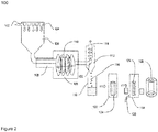
- FIG. 2 illustrates the system 100 for fabrication of the glass preform 122, in accordance with another embodiment of the present disclosure.
- FIG. 2 shows an arrangement of components of the system 100. The components of FIG. 2 are similar to the various components of FIG. 1 .
- the system 100 includes the combustion chamber 106, the plurality of agglomerator tubes 110, the cooling layer 108, the cyclone separator 112, the soot collection chamber 118 and the preform compaction chamber 120.
- the system 100 includes a controlled atmospheric furnace 130 (as shown in FIG. 2 ).
- the soot particles 116 are filled inside the preform compaction chamber 120. Further, the soot particles 116 undergo compaction with facilitation of the preform compaction chamber 120. In an embodiment of the present disclosure, the soot particles 116 are compacted using cold uniaxial compaction process. In another embodiment of the present disclosure, the soot particles 116 are compacted using cold isostatic compaction process. In yet another embodiment of the present disclosure, the soot particles 116 are compacted using the cold uniaxial compaction process and the cold isostatic compaction process. In yet another embodiment of the present disclosure, the compaction process of the soot particles 116 may vary. In an embodiment of the present disclosure, the compaction of the soot particles 116 results in formation of the soot preform 124.
- the soot preform 124 is placed inside the controlled atmospheric furnace 130.
- the controlled atmospheric furnace 130 provides high temperature to the soot preform 124.
- the high temperature inside the controlled atmospheric furnace 130 facilitates dehydration of the soot preform 124.
- the dehydration of the soot preform 124 is done with continuous facilitation of the dehydration gas through the dehydration gas inlet 126.
- the dehydration gas includes but may not be limited to chlorine.
- the chlorine removes the OH ion concentration from the soot preform 124.
- the required temperature maintained for the dehydration may not be limited to 1050° Celsius to 1150° Celsius.
- the required temperature maintained by the sintering furnace 130 may not be limited to 1500° Celsius to 1600° Celsius for sintering of the compacted soot particles.
- the high temperature inside the controlled atmospheric furnace 130 facilitates sintering of the soot preform 124 to obtain the desired shape and size of the glass preform.
- preform 124 may be further drawn into optical fibre directly or may be a cladding preform further utilized in RIC process.
- the sintering of the compacted soot preform 124 in the controlled atmospheric furnace 130 results in formation of the glass preform 128.
- FIG. 3 illustrates a flow chart 200 depicting a method for fabrication of the glass preform 128, in accordance with various embodiment of the present disclosure. It may be noted that to explain the process steps of the flowchart 200, references will be made to the system components of FIG. 1 and FIG. 2 . It may also be noted that the flowchart 200 may have lesser or more number of steps.
- the flow chart 200 initiates at step 202.
- the method includes production of the soot particles 116 in the combustion chamber 106.
- the combustion chamber 106 is using purging gas.
- the purging gas is used to maintain the temperature inside the combustion chamber 106.
- the soot particles 116 are produced by heating the precursor material with facilitation of the plurality of burners 104.
- the heating of the precursor material produces the soot particles 116 along with the one or more impurities.
- the one or more impurities include HCI and water vapors.
- the method includes the agglomeration of soot particles 116 performed in the plurality of agglomerator tubes 110.
- the soot particles 116 are agglomerated inside the plurality of agglomerator tubes 110 with the facilitation of the cooling layer 108.
- the cooling layer 108 reduces overall temperature of the soot particles 116.
- the soot particles 116 are agglomerated is of uniform and desired size.
- the soot particles 116 along with the one or more impurities are inserted in the cyclone separator 112 through the first inlet 122.
- the soot particles 116 along with the one or more impurities may be separated by the methods of ESP or Bagfilter.
- the method includes separation of the soot particles 116 from the one or more impurities in the cyclone separator 112. Further, the one or more impurities passes out of the cyclone separator 112 through the outlet 114.
- the method includes the collection of the soot particles 116 inside the soot collection chamber 118.
- the method includes the compaction of the soot particles 116 inside the preform compaction chamber 120. Further, the soot particles undergo dehydration at the high temperature with continuous facilitation of the dehydration gas. Furthermore, the dehydration gas includes but may not be limited to chlorine. Moreover, the compaction of the soot particles 116 followed by sintering results in formation of the glass preform 128.
- the flow chart terminates at step 214.
- the present disclosure provides numerous advantages over the prior art.
- the present disclosure provides an improved method for fabrication of the glass preform with high efficiency.
- the method used for fabrication of the glass preform is cost effective and requires less overall process time. Further, the method provides ease of operation during fabrication of the glass preform.
- the method is applicable for fabrication of both core and clad for optical fibres. Moreover, the method is applicable for fabrication of a pure silica core and a pure silica clad.
Landscapes
- Chemical & Material Sciences (AREA)
- Organic Chemistry (AREA)
- Engineering & Computer Science (AREA)
- Materials Engineering (AREA)
- Manufacturing & Machinery (AREA)
- Inorganic Chemistry (AREA)
- Life Sciences & Earth Sciences (AREA)
- Geochemistry & Mineralogy (AREA)
- Dispersion Chemistry (AREA)
- Chemical Kinetics & Catalysis (AREA)
- General Chemical & Material Sciences (AREA)
- General Life Sciences & Earth Sciences (AREA)
- Thermal Sciences (AREA)
- Physics & Mathematics (AREA)
- Manufacture, Treatment Of Glass Fibers (AREA)
Abstract
Description
- The present disclosure relates to the field of optical fibre. More particularly, the present disclosure relates to a method for fabrication of a glass preform.
- Over the last few years, optical fibers are widely used for network communication due to enormous benefits over metal wires. The increasing demand of the optical fibers leads to mass production of optical fibre preform. Conventionally, the optical fibre preform are manufactured using various methods. The various methods include but may not be limited to outside vapor deposition (OVD) and vapor axial deposition (VAD). The basic process involved in the OVD is called "flame hydrolysis". In this process, SiCl4 reacts with oxygen (O) and hydrogen (H2) to produce silica (SiO2), hydrogen chloride (HCl), and water vapor (H2O). In addition, the OVD process is a limiting process with complex machine designs for fabrication of the optical fibre preform in bulk. Furthermore, fabrication of the optical fibre preform using the OVD process leads to reduced materials efficiency. Due to reduced materials efficiency the running cost is high and also consumes time.
- In light of the above stated discussion, there is a need for an improved method for fabrication of a glass preform.
- In an aspect, the present disclosure provides a method for fabrication of a glass preform. The method includes production of soot particles in a combustion chamber using a precursor material. The soot particles are silica particles. In addition, the method includes agglomeration of the soot particles. Further, the method includes separation of the soot particles from the one or more impurities. Furthermore, the method includes collection of the soot particles. Moreover, the method includes compaction of the soot particles. Also, the soot particles are produced by heating the precursor material with facilitation of a plurality of burners. The heating of the precursor material produces the soot particles along with one or more impurities. Also, the agglomeration is performed using a plurality of agglomerator tubes. The soot particles are agglomerated based on size of the plurality of agglomerator tubes. Also, the separation of the soot particles is performed in a cyclone separator. Also, the collection of the soot particles is performed in a soot collection chamber. Also, the soot particles are compacted with facilitation of a preform compaction chamber. The compaction followed by sintering of the compacted soot particles results in formation of the glass preform.
- In an embodiment of the present disclosure, the combustion chamber includes the plurality of burners and an inlet. The combustion chamber is filled with a purging gas. The inlet is used for insertion of purging gas in the combustion chamber. The gases in the combustion chamber for generation of heat may be hydrogen (H2) and oxygen (O) or CH4 and Oxygen (O).
- In an embodiment of the present disclosure, the combustion chamber is made of hastelloy material.
- In an embodiment of the present disclosure, the one or more impurities include HCI and water vapors.
- In an embodiment of the present disclosure, the precursor material is at least one of silicon tetrachloride (SiCl4) or octamethylcyclotetrasiloxane (OMCTS or D4).
- In an embodiment of the present disclosure, the plurality of agglomerator tubes is surrounded by a cooling layer. The cooling layer facilitates cooling of the soot particles inside the plurality of agglomerator tubes.
- In an embodiment of the present disclosure, the cyclone separator facilitates separation of the soot particles from the one or more impure gases.
- In an embodiment of the present disclosure, the compaction of the soot particles is performed using at least one of uniaxial compaction process, cold isostatic compaction process and hot isostatic compaction process.
- In an embodiment of the present disclosure, the compaction of the soot particles is performed with continuous facilitation of a dehydration gas. The dehydration gas is at least one of chlorine. The dehydration gas removes an OH ion concentration from a soot preform.
- In an embodiment of the present disclosure, the compaction of the soot particles in the preform compaction chamber. In addition, the multiple dopants can be added to the silicon dioxide particles before compaction and multiple layer of dopants can be compacted with facilitation of combination of uniaxial compaction process, isostatic compaction process, and hot isostatic compaction process.
- The sintering of the compacted soot particles will be performed to form the glass preform. The glass preform produced is of high efficiency.
- Having thus described the disclosure in general terms, reference will now be made to the accompanying figures, wherein:
-
FIG. 1 illustrates a system for fabrication of a glass preform, in accordance with an embodiment of the present disclosure; -
FIG. 2 illustrates a system for fabrication of the glass preform, in accordance with another embodiment of the present disclosure; and -
FIG. 3 illustrates a flow chart depicting a method for fabrication of the glass preform, in accordance with various embodiments of the present disclosure. - It should be noted that the accompanying figures are intended to present illustrations of few exemplary embodiments of the present disclosure. These figures are not intended to limit the scope of the present disclosure. It should also be noted that accompanying figures are not necessarily drawn to scale.
- Reference will now be made in detail to selected embodiments of the present disclosure in conjunction with accompanying figures. The embodiments described herein are not intended to limit the scope of the disclosure, and the present disclosure should not be construed as limited to the embodiments described. This disclosure may be embodied in different forms without departing from the scope and spirit of the disclosure. It should be understood that the accompanying figures are intended and provided to illustrate embodiments of the disclosure described below and are not necessarily drawn to scale. In the drawings, like numbers refer to like elements throughout, and thicknesses and dimensions of some components may be exaggerated for providing better clarity and ease of understanding.
- It should be noted that the terms "first", "second", and the like, herein do not denote any order, ranking, quantity, or importance, but rather are used to distinguish one element from another. Further, the terms "a" and "an" herein do not denote a limitation of quantity, but rather denote the presence of at least one of the referenced item.
-
FIG. 1 illustrates asystem 100 for fabrication of aglass preform 128, in accordance with an embodiment of the present disclosure.FIG. 1 shows an arrangement of various components of thesystem 100. Thesystem 100 enables a process for fabrication of theglass preform 128. In general, glass preform is large glass body being used to draw optical fibres. In addition, it is to be understood that, glass body may be a hollow cylindrical glass body, transparent glass body, solid glass body or colored glass body. In addition, glass preform is fabricated by using one or more manufacturing techniques. Further, one or more manufacturing techniques include but may not be limited to outside vapor deposition and vapor axial deposition. - The
system 100 includes acombustion chamber 106, a plurality ofagglomerator tubes 110, acooling layer 108, acyclone separator 112, asoot collection chamber 118, apreform compaction chamber 120 andsintering furnace 130. - The
system 100 includes thecombustion chamber 106. In addition, thecombustion chamber 106 is made of hastelloy material. In general, hastelloy material is superalloy made up of nickel-molybdenum-chromium. In addition, hastelloy provides high-corrosion resistance from environment. Further, the hastelloy material is used to bear high temperature. In general, combustion chamber is enclosed space that enables combustion. Thecombustion chamber 106 includes aninlet 102 and a plurality ofburners 104. In general, the gases in the combustion chamber for generation of heat may be Hydrogen (H2) or Oxygen (O) or CH4 and Oxygen (O). In an embodiment of the present disclosure, thecombustion chamber 106 is filled with a purging gas through theinlet 102. In addition, the purging gas is used to maintain the temperature inside the combustion chamber. 106. In an example, purging gas is nitrogen. In yet another example, the purging gas is any suitable gas of the like. - In an embodiment of the present disclosure, the
combustion chamber 106 is utilized to producesoot particles 116 using a precursor material. In general, soot corresponds to powdery or flaky substance consisting of silica. Thesoot particles 116 are produced by heating the precursor material with facilitation of the plurality of burners 104.In general, the primary size of the generated particles is 0.1 micron. The primary level of agglomeration happens along the combustible gas flame as well. In addition, the heating of the precursor material produces thesoot particles 116 along with one or more impurities. Further, the one or more impurities are HCl and water vapors if precursor is SiCl4. In general, precursor material is compound that participates in chemical reaction to produce another compound. In addition, precursor material is raw material used to manufacture silica soot particles. - In an embodiment of the present disclosure, the precursor material is at least one of silicon tetrachloride (SiCl4) or octamethylcyclotetrasiloxane (OMCTS or D4). In general, octamethylcyclotetrasiloxane is organosilicon compound with chemical formula [(CH3)2SiO]4. In addition, octamethylcyclotetrasiloxane is colorless viscous liquid. In another embodiment of the present disclosure, the precursor material may vary.
- The
system 100 includes the plurality ofagglomerator tubes 110. In addition, the plurality ofagglomerator tubes 110 is surrounded by thecooling layer 108. Further, thecooling layer 108 reduces overall temperature of thesoot particles 116 along with the one or more impurities. In an embodiment of the present disclosure, thesoot particles 116 along with the one or more impurities undergo agglomeration inside the plurality ofagglomerator tubes 110. In addition, thesoot particles 116 are agglomerated inside the plurality ofagglomerator tubes 110 with facilitation of thecooling layer 108. In general, agglomeration is process of collecting in mass and refers to sticking of soot particles to one another. In an embodiment of the present disclosure, thesoot particles 116 are agglomerated is of uniform and desired size. In an embodiment of the present disclosure, the agglomeratedtubes 110 and coolinglayers 108 may kept as nonfunctional based on the particle size requirement. In an embodiment of the present disclosure, the agglomeration of thesilicon dioxide particles 108 is performed for the range of 1 to 100 micron silicon dioxide particles diameter. In an embodiment of the present disclosure, the agglomeration of thesilicon dioxide particles 108 is performed for the average silicon dioxide particles sizes in the range of 10 to 40 micron diameter. The average silicon dioxide particles sizes decides the collection efficiency of the cyclone separator. - The
system 100 includes thecyclone separator 112. Thecyclone separator 112 includes afirst inlet 122 and anoutlet 114. In an embodiment of the present disclosure, thesoot particles 116 along with the one or more impurities are released inside thecyclone separator 112 through thefirst inlet 122. In general, cyclone separator uses centrifugal force that produces particles in swirl flow and separates out particles due to gravity force. In an embodiment of the present disclosure, thecyclone separator 112 facilitates separation of thesoot particles 116 from the one or more impurities. In an embodiment of the present disclosure, the one or more impurities passes out of thecyclone separator 112 through theoutlet 114. In addition, thesoot particles 116 are collected in thesoot collection chamber 118. Further, thesoot particles 116 are in powdered form. In an embodiment of the present disclosure, thecyclone separator 114 receives the particle sizes in the range of 10 micron to 40 micron in diameter and separates thesesilicon dioxide particles 108 from the waste particulates. In an embodiment of the present disclosure, thecyclone separator 114 also separates the particles sizes more than 40 micron in diameter from the waste particulates. Thesoot particles 116 are collected in the soot collection chamber 118 (as shown inFIG 1 ). - The
system 100 includes thepreform compaction chamber 120. In general, the end loss of soot making process which typically contribute 20% - 30% depend on size of soot. This compaction system can reduce end loss by more than 50 %. In an embodiment of the present disclosure, thepreform compaction chamber 120 is utilized to perform compaction of thesilicon dioxide particles 108 with very low curvature surfaces at both end to represent the cone which can reduce end loss by more than 50 % compared to conventional optical fibre manufacturing process. In an embodiment of the present disclosure, thepreform compaction chamber 120 is utilized to perform compaction of thesilicon dioxide particles 108 to provide cone free preform. In addition, thepreform compaction chamber 120 is used to maintain high temperature. Further, the preform compaction chamber is connected to adehydration gas inlet 126. In an embodiment of the present disclosure, thepreform compaction chamber 120 facilitates compaction of thesoot particles 116. In addition, the compaction of thesoot particles 116 is performed with continuous facilitation of a dehydration gas through thedehydration gas inlet 126. Further, dehydration of thesoot particles 116 is done at high temperature maintained by thepreform compaction chamber 120. Furthermore, the dehydration gas released inside thepreform compaction chamber 120 includes but may not be limited to chlorine. Moreover, the dehydration gas removes an OH ion concentration of thesoot particles 116. In addition, the required temperature maintained for the dehydration may not be limited to 1050° Celsius to 1150° Celsius. In an embodiment of the present disclosure, thepreform compaction chamber 120 provides compaction of soot preform length in the range of 0.5 m to 2 m and final compaction preform diameter in the range of 0.05 m to 0.35 m . The chamber provides preform compaction length is not limited to aforementioned range of length 0.5 m to 2 m and diameter range of the compacted preform is 0.05 m to 0.35 m. In an embodiment of the present disclosure, thepreform compaction chamber 120 has capability for sintering the compacted soot particles throughsintering furnace 130. In an embodiment of the present disclosure, after the sintering of the dehydrated compacted soot particles, desired size and shape of the glass preform is achieved within acceptable range of preform diameter variations. The preform compaction process corresponds to the pressing of the silica particles in the presence of binders. The binders may be selected from but not limited to Poly propylene carbonate, Polyvinyl alcohol, Poly Styrene, Camphor, and Gelatin based Agar. The concentration of the binders lies in the range of about 100 ppm to 10,000 ppm. In an example of the present disclosure the concentration of the binders may be of any other suitable range. - In an embodiment of the present disclosure, the compaction of the
soot particles 116 results in generation of asoot preform 124. In an embodiment of the present disclosure, the compaction of thesoot particles 116 is performed using at least one of uniaxial compaction process, cold isostatic compaction process and hot isostatic compaction process. In an embodiment of the present disclosure, thepreform compaction chamber 120 is utilized to perform compaction of the silicon dioxide particles with the different dopants. In an embodiment of the present disclosure, thepreform compaction chamber 120 is utilized to perform compaction of the silicon dioxide particles with multiple layer of dopant with same or different precursors. In an embodiment of the present disclosure, thepreform compaction chamber 120 has capability for sintering the compacted soot particles throughsintering furnace 130. - In an embodiment of the present disclosure, the
soot particles 116 are compacted with facilitation of hot uniaxial compaction process. In another embodiment of the present disclosure, thesoot particles 116 are compacted with facilitation of hot isostatic compaction process. In yet another embodiment of the present disclosure, thesoot particles 116 are compacted with facilitation of hot uniaxial compaction process and hot isostatic compaction process. In yet another embodiment of the present disclosure, the compaction process of thesoot particles 116 may vary. In general, hot uniaxial compaction is process of compacting particles by applying pressure in one direction. In general, hot isostatic compaction is process of compacting particles by applying pressure in all direction. In addition, hot isostatic compaction increases density of particles. In general, hot uniaxial compaction and hot isostatic compaction provides densification in combine effect of high pressure and high temperature. In an embodiment of the present disclosure, thesoot preform 124 is heat up in thepreform compaction chamber 120 at required temperature. In addition, the required temperature maintained by thepreform compaction chamber 120 may not be limited to 1000° Celsius to 1200° Celsius for compaction of soot particles. In an embodiment of the present disclosure, thepreform compaction chamber 120 has capability for sintering the compacted soot particles throughsintering furnace 130. In an embodiment of the present disclosure, thesoot preform 124 sintered bysintered furnace 130 at high temperature results in formation of theglass preform 128. In addition, the required temperature maintained by thesintering furnace 130 may not be limited to 1500° Celsius to 1600° Celsius for sintering of the compacted soot particles. -
FIG. 2 illustrates thesystem 100 for fabrication of theglass preform 122, in accordance with another embodiment of the present disclosure.FIG. 2 shows an arrangement of components of thesystem 100. The components ofFIG. 2 are similar to the various components ofFIG. 1 . Thesystem 100 includes thecombustion chamber 106, the plurality ofagglomerator tubes 110, thecooling layer 108, thecyclone separator 112, thesoot collection chamber 118 and thepreform compaction chamber 120. In addition, thesystem 100 includes a controlled atmospheric furnace 130 (as shown inFIG. 2 ). - The
soot particles 116 are filled inside thepreform compaction chamber 120. Further, thesoot particles 116 undergo compaction with facilitation of thepreform compaction chamber 120. In an embodiment of the present disclosure, thesoot particles 116 are compacted using cold uniaxial compaction process. In another embodiment of the present disclosure, thesoot particles 116 are compacted using cold isostatic compaction process. In yet another embodiment of the present disclosure, thesoot particles 116 are compacted using the cold uniaxial compaction process and the cold isostatic compaction process. In yet another embodiment of the present disclosure, the compaction process of thesoot particles 116 may vary. In an embodiment of the present disclosure, the compaction of thesoot particles 116 results in formation of thesoot preform 124. - The
soot preform 124 is placed inside the controlledatmospheric furnace 130. In an embodiment of the present disclosure, the controlledatmospheric furnace 130 provides high temperature to thesoot preform 124. In addition, the high temperature inside the controlledatmospheric furnace 130 facilitates dehydration of thesoot preform 124. Further, the dehydration of thesoot preform 124 is done with continuous facilitation of the dehydration gas through thedehydration gas inlet 126. Furthermore, the dehydration gas includes but may not be limited to chlorine. Moreover, the chlorine removes the OH ion concentration from thesoot preform 124. In addition, the required temperature maintained for the dehydration may not be limited to 1050° Celsius to 1150° Celsius. In addition, the required temperature maintained by thesintering furnace 130 may not be limited to 1500° Celsius to 1600° Celsius for sintering of the compacted soot particles. In addition, the high temperature inside the controlledatmospheric furnace 130 facilitates sintering of thesoot preform 124 to obtain the desired shape and size of the glass preform. In an embodiment of the present disclosure, preform 124 may be further drawn into optical fibre directly or may be a cladding preform further utilized in RIC process. In an embodiment of the present disclosure, the sintering of the compactedsoot preform 124 in the controlledatmospheric furnace 130 results in formation of theglass preform 128. -
FIG. 3 illustrates a flow chart 200 depicting a method for fabrication of theglass preform 128, in accordance with various embodiment of the present disclosure. It may be noted that to explain the process steps of the flowchart 200, references will be made to the system components ofFIG. 1 andFIG. 2 . It may also be noted that the flowchart 200 may have lesser or more number of steps. - The flow chart 200 initiates at
step 202. Followingstep 202, atstep 204, the method includes production of thesoot particles 116 in thecombustion chamber 106. In addition, thecombustion chamber 106 is using purging gas. Further, the purging gas is used to maintain the temperature inside thecombustion chamber 106. Furthermore, thesoot particles 116 are produced by heating the precursor material with facilitation of the plurality ofburners 104. Moreover, the heating of the precursor material produces thesoot particles 116 along with the one or more impurities. Also, the one or more impurities include HCI and water vapors. - At
step 206, the method includes the agglomeration ofsoot particles 116 performed in the plurality ofagglomerator tubes 110. In addition, thesoot particles 116 are agglomerated inside the plurality ofagglomerator tubes 110 with the facilitation of thecooling layer 108. Further, thecooling layer 108 reduces overall temperature of thesoot particles 116. Furthermore, thesoot particles 116 are agglomerated is of uniform and desired size. Furthermore, thesoot particles 116 along with the one or more impurities are inserted in thecyclone separator 112 through thefirst inlet 122. Furthermore, thesoot particles 116 along with the one or more impurities may be separated by the methods of ESP or Bagfilter. Atstep 208, the method includes separation of thesoot particles 116 from the one or more impurities in thecyclone separator 112. Further, the one or more impurities passes out of thecyclone separator 112 through theoutlet 114. - At
step 210, the method includes the collection of thesoot particles 116 inside thesoot collection chamber 118. Atstep 212, the method includes the compaction of thesoot particles 116 inside thepreform compaction chamber 120. Further, the soot particles undergo dehydration at the high temperature with continuous facilitation of the dehydration gas. Furthermore, the dehydration gas includes but may not be limited to chlorine. Moreover, the compaction of thesoot particles 116 followed by sintering results in formation of theglass preform 128. The flow chart terminates atstep 214. - The present disclosure provides numerous advantages over the prior art. The present disclosure provides an improved method for fabrication of the glass preform with high efficiency. In addition, the method used for fabrication of the glass preform is cost effective and requires less overall process time. Further, the method provides ease of operation during fabrication of the glass preform. Furthermore, the method is applicable for fabrication of both core and clad for optical fibres. Moreover, the method is applicable for fabrication of a pure silica core and a pure silica clad.
- The foregoing descriptions of pre-defined embodiments of the present technology have been presented for purposes of illustration and description. They are not intended to be exhaustive or to limit the present technology to the precise forms disclosed, and obviously many modifications and variations are possible in light of the above teaching. The embodiments were chosen and described in order to best explain the principles of the present technology and its practical application, to thereby enable others skilled in the art to best utilize the present technology and various embodiments with various modifications as are suited to the particular use contemplated. It is understood that various omissions and substitutions of equivalents are contemplated as circumstance may suggest or render expedient, but such are intended to cover the application or implementation without departing from the spirit or scope of the claims of the present technology.
Claims (12)
- A method for fabrication of a glass preform (128), the method comprising:production of soot particles (116) in a combustion chamber (106) using a precursor material, wherein the soot particles (116) are produced by heating the precursor material with facilitation of a plurality of burners (104), wherein the heating of the precursor material produces the soot particles (116) along with one or more impurities;agglomeration of the soot particles (116), wherein the agglomeration is performed using a plurality of agglomerator tubes (110), wherein the soot particles (116) are agglomerated based on size of the plurality of agglomerator tubes (110);separation of the soot particles (116) from the one or more impurities, wherein the separation of the soot particles (116) is performed in a cyclone separator (112);collection of the soot particles (116), wherein the collection of the soot particles (116) is performed in a soot collection chamber (118); andcompaction of the soot particles (116), wherein the soot particles (116) are compacted with facilitation of a preform compaction chamber (120), wherein the compaction of the soot particles (116) followed by sintering results in formation of the glass preform (128).
- The method as recited in claim 1, wherein the combustion chamber (106) comprises the plurality of burners (104) and an inlet (102), wherein the combustion chamber (106) is filled with a purging gas, wherein the inlet (102) is used for releasing the purging gas in the combustion chamber (106).
- The method as recited in claim 1 or claim 2, wherein the combustion chamber (106) is made of hastelloy material.
- The method as recited in any preceding claim, wherein the one or more impurities comprising HCl and water vapors if precursor material is silicon tetrachloride (SiCl4).
- The method as recited in any preceding claim, wherein the precursor material is at least one of silicon tetrachloride (SiCl4) or octamethylcyclotetrasiloxane (OMCTS or D4).
- The method as recited in any preceding claim, wherein the plurality of agglomerator tubes (110) is surrounded by a cooling layer (108), wherein the cooling layer (108) facilitates cooling of the soot particles (116) inside the plurality of agglomerator tubes (110).
- The method as recited in any preceding claim, wherein the cyclone separator (112) facilitates separation of the soot particles (116) from the one or more impurities.
- The method as recited in any preceding claim, wherein the compaction of the soot particles (116) is performed using at least one of uniaxial compaction process, cold isostatic compaction process and hot isostatic compaction process.
- The method as recited in any one of claims 1 to 8, wherein the compaction of the soot particles (116) is performed with continuous facilitation of a dehydration gas, wherein the dehydration gas is at least one of chlorine, wherein the dehydration gas removes an OH ion concentration from a soot preform (124).
- The method as recited in any preceding claim, wherein the sintering of the compacted soot preform (124) in the preform compaction chamber (120) leads to formation of a glass preform (128), wherein the glass preform (128) produced is of high efficiency.
- The method as recited in any preceding claim, wherein the dehydration performed in the controlled atmospheric furnace (130) with continuous facilitation of a dehydration gas, wherein the dehydration gas is at least one of chlorine, wherein the dehydration gas removes an OH ion concentration from a soot preform (124)
- The method as recited in any preceding claim, wherein the sintering of the compacted soot preform (124) in the controlled atmospheric furnace (130) leads to formation of a glass preform (128), wherein the glass preform (128) produced is of high efficiency.
Applications Claiming Priority (1)
| Application Number | Priority Date | Filing Date | Title |
|---|---|---|---|
| IN201921032707 | 2019-08-13 |
Publications (2)
| Publication Number | Publication Date |
|---|---|
| EP3778503A1 true EP3778503A1 (en) | 2021-02-17 |
| EP3778503B1 EP3778503B1 (en) | 2026-07-08 |
Family
ID=72087882
Family Applications (1)
| Application Number | Title | Priority Date | Filing Date |
|---|---|---|---|
| EP20191006.4A Active EP3778503B1 (en) | 2019-08-13 | 2020-08-13 | Method for fabrication of glass preform |
Country Status (3)
| Country | Link |
|---|---|
| US (1) | US11912604B2 (en) |
| EP (1) | EP3778503B1 (en) |
| CN (1) | CN112194359A (en) |
Families Citing this family (1)
| Publication number | Priority date | Publication date | Assignee | Title |
|---|---|---|---|---|
| CN115745392B (en) * | 2022-12-07 | 2024-04-05 | 中国工程物理研究院激光聚变研究中心 | Method for recycling MCVD tail ash and preparing rare earth doped optical fiber preform |
Citations (5)
| Publication number | Priority date | Publication date | Assignee | Title |
|---|---|---|---|---|
| EP0054530A1 (en) * | 1980-12-12 | 1982-06-23 | Gösta Lennart Flemmert | Process and apparatus for preparing finely-divided silicon dioxide having high thickening capacity and good thixotropic properties |
| DE3338888A1 (en) * | 1982-11-01 | 1984-05-03 | General Electric Co., Schenectady, N.Y. | Process for preparing pyrogenic silicon dioxide |
| US4508538A (en) * | 1977-01-24 | 1985-04-02 | The Dow Chemical Company | Recovery of fumed SiO2 |
| US5340560A (en) * | 1993-04-30 | 1994-08-23 | General Electric Company | Method for making fumed silica having a reduced aggregate size and product |
| WO2018005584A1 (en) * | 2016-06-30 | 2018-01-04 | Corning Incorporated | Method of making optical fiber preform with pressed soot and rods |
Family Cites Families (4)
| Publication number | Priority date | Publication date | Assignee | Title |
|---|---|---|---|---|
| US3423324A (en) * | 1964-11-20 | 1969-01-21 | Owens Illinois Inc | Apparatus and method for producing silica and other oxides |
| DE4322804A1 (en) * | 1993-07-08 | 1995-01-12 | Wacker Chemie Gmbh | Process for the production of highly disperse silica and device for carrying out the process |
| EP1700828A1 (en) * | 2005-03-09 | 2006-09-13 | Degussa AG | Method for producing ultra-high purity, optical quality, glass articles |
| JP2019526737A (en) * | 2016-08-25 | 2019-09-19 | コーニング インコーポレイテッド | Segmented thermal barrier for internal combustion engine and method of manufacturing the same |
-
2020
- 2020-08-13 US US16/993,182 patent/US11912604B2/en active Active
- 2020-08-13 CN CN202010813278.6A patent/CN112194359A/en active Pending
- 2020-08-13 EP EP20191006.4A patent/EP3778503B1/en active Active
Patent Citations (5)
| Publication number | Priority date | Publication date | Assignee | Title |
|---|---|---|---|---|
| US4508538A (en) * | 1977-01-24 | 1985-04-02 | The Dow Chemical Company | Recovery of fumed SiO2 |
| EP0054530A1 (en) * | 1980-12-12 | 1982-06-23 | Gösta Lennart Flemmert | Process and apparatus for preparing finely-divided silicon dioxide having high thickening capacity and good thixotropic properties |
| DE3338888A1 (en) * | 1982-11-01 | 1984-05-03 | General Electric Co., Schenectady, N.Y. | Process for preparing pyrogenic silicon dioxide |
| US5340560A (en) * | 1993-04-30 | 1994-08-23 | General Electric Company | Method for making fumed silica having a reduced aggregate size and product |
| WO2018005584A1 (en) * | 2016-06-30 | 2018-01-04 | Corning Incorporated | Method of making optical fiber preform with pressed soot and rods |
Non-Patent Citations (1)
| Title |
|---|
| "Ullmann's Encyclopedia of Industrial Chemistry", 15 April 2008, WILEY-VCH, Weinheim, ISBN: 978-3-527-30673-2, article OTTO W. FL�RKE ET AL: "Silica", pages: 478 - 485, XP055758544, DOI: 10.1002/14356007.a23_583.pub3 * |
Also Published As
| Publication number | Publication date |
|---|---|
| US20210047223A1 (en) | 2021-02-18 |
| CN112194359A (en) | 2021-01-08 |
| EP3778503B1 (en) | 2026-07-08 |
| US11912604B2 (en) | 2024-02-27 |
Similar Documents
| Publication | Publication Date | Title |
|---|---|---|
| EP1808417B1 (en) | Method for fabricating glass bodies using an aerosol delivery system | |
| CN104271521B (en) | For manufacturing the compacting multi-layer silica dioxide soot performing member of single sintering step, complex index of refraction profile fiber | |
| EP0463045B1 (en) | Improved vitreous silica products | |
| US4082420A (en) | An optical transmission fiber containing fluorine | |
| CA1165551A (en) | Optical fiber fabrication and resulting product | |
| US4161505A (en) | Process for producing optical transmission fiber | |
| JP2014527012A (en) | Method for manufacturing optical fiber preform having low refractive index trench | |
| US4242375A (en) | Process for producing optical transmission fiber | |
| US11912604B2 (en) | Method for fabrication of glass preform | |
| JP2017007941A (en) | Production method of glass preform | |
| EP3423419B1 (en) | A method for manufacturing a preform for optical fibers | |
| CN101479204B (en) | Process for producing optical fiber base and apparatus therefor | |
| EP3805165B1 (en) | Method for fabrication of optical fibre soot preform | |
| CN1337367A (en) | Manufacture of prefabricated fiber rod | |
| US20210214266A1 (en) | Organic germania and silica sources for making optical fiber preforms | |
| US20230286851A1 (en) | Method for manufacturing optical fiber preform | |
| Mat-Sharif et al. | Effect of GeCl 4/SiCl 4 flow ratio on Germanium incorporation in MCVD process | |
| US4537611A (en) | Method for manufacturing glass from the gas phase | |
| JP5867976B2 (en) | Optical fiber preform manufacturing method | |
| JP5533205B2 (en) | Glass base material manufacturing method | |
| US11634351B2 (en) | Method for sintering of optical fibre preform | |
| CN100429539C (en) | Method for making optical fibre with low E-waveband and L-waveband loss wave peak | |
| US11655183B2 (en) | System and method for optical fiber preform preparation via high-surface-area coating | |
| CN116573847A (en) | Optical fiber preform and preparation method thereof | |
| WO2006083354A2 (en) | Low-water optical fiber preform and process for making it |
Legal Events
| Date | Code | Title | Description |
|---|---|---|---|
| PUAI | Public reference made under article 153(3) epc to a published international application that has entered the european phase |
Free format text: ORIGINAL CODE: 0009012 |
|
| STAA | Information on the status of an ep patent application or granted ep patent |
Free format text: STATUS: THE APPLICATION HAS BEEN PUBLISHED |
|
| AK | Designated contracting states |
Kind code of ref document: A1 Designated state(s): AL AT BE BG CH CY CZ DE DK EE ES FI FR GB GR HR HU IE IS IT LI LT LU LV MC MK MT NL NO PL PT RO RS SE SI SK SM TR |
|
| AX | Request for extension of the european patent |
Extension state: BA ME |
|
| STAA | Information on the status of an ep patent application or granted ep patent |
Free format text: STATUS: REQUEST FOR EXAMINATION WAS MADE |
|
| 17P | Request for examination filed |
Effective date: 20211117 |
|
| RBV | Designated contracting states (corrected) |
Designated state(s): AL AT BE BG CH CY CZ DE DK EE ES FI FR GB GR HR HU IE IS IT LI LT LU LV MC MK MT NL NO PL PT RO RS SE SI SK SM TR |
|
| STAA | Information on the status of an ep patent application or granted ep patent |
Free format text: STATUS: EXAMINATION IS IN PROGRESS |
|
| 17Q | First examination report despatched |
Effective date: 20240129 |
|
| GRAP | Despatch of communication of intention to grant a patent |
Free format text: ORIGINAL CODE: EPIDOSNIGR1 |
|
| STAA | Information on the status of an ep patent application or granted ep patent |
Free format text: STATUS: GRANT OF PATENT IS INTENDED |
|
| INTG | Intention to grant announced |
Effective date: 20260107 |
|
| GRAS | Grant fee paid |
Free format text: ORIGINAL CODE: EPIDOSNIGR3 |
|
| GRAA | (expected) grant |
Free format text: ORIGINAL CODE: 0009210 |
|
| STAA | Information on the status of an ep patent application or granted ep patent |
Free format text: STATUS: THE PATENT HAS BEEN GRANTED |
|
| AK | Designated contracting states |
Kind code of ref document: B1 Designated state(s): AL AT BE BG CH CY CZ DE DK EE ES FI FR GB GR HR HU IE IS IT LI LT LU LV MC MK MT NL NO PL PT RO RS SE SI SK SM TR |
|
| REG | Reference to a national code |
Ref country code: CH Ref legal event code: F10 Free format text: ST27 STATUS EVENT CODE: U-0-0-F10-F00 (AS PROVIDED BY THE NATIONAL OFFICE) Effective date: 20260708 Ref country code: GB Ref legal event code: FG4D |
|
| REG | Reference to a national code |
Ref country code: IE Ref legal event code: FG4D |
|
| REG | Reference to a national code |
Ref country code: DE Ref legal event code: R096 Ref document number: 602020074089 Country of ref document: DE |