EP3778459A1 - Layer transfer device - Google Patents
Layer transfer device Download PDFInfo
- Publication number
- EP3778459A1 EP3778459A1 EP19777786.5A EP19777786A EP3778459A1 EP 3778459 A1 EP3778459 A1 EP 3778459A1 EP 19777786 A EP19777786 A EP 19777786A EP 3778459 A1 EP3778459 A1 EP 3778459A1
- Authority
- EP
- European Patent Office
- Prior art keywords
- roller
- sheet
- multilayer film
- transfer device
- film
- Prior art date
- Legal status (The legal status is an assumption and is not a legal conclusion. Google has not performed a legal analysis and makes no representation as to the accuracy of the status listed.)
- Granted
Links
Images

Classifications
-
- G—PHYSICS
- G03—PHOTOGRAPHY; CINEMATOGRAPHY; ANALOGOUS TECHNIQUES USING WAVES OTHER THAN OPTICAL WAVES; ELECTROGRAPHY; HOLOGRAPHY
- G03G—ELECTROGRAPHY; ELECTROPHOTOGRAPHY; MAGNETOGRAPHY
- G03G15/00—Apparatus for electrographic processes using a charge pattern
- G03G15/65—Apparatus which relate to the handling of copy material
- G03G15/6555—Handling of sheet copy material taking place in a specific part of the copy material feeding path
- G03G15/6573—Feeding path after the fixing point and up to the discharge tray or the finisher, e.g. special treatment of copy material to compensate for effects from the fixing
-
- G—PHYSICS
- G03—PHOTOGRAPHY; CINEMATOGRAPHY; ANALOGOUS TECHNIQUES USING WAVES OTHER THAN OPTICAL WAVES; ELECTROGRAPHY; HOLOGRAPHY
- G03G—ELECTROGRAPHY; ELECTROPHOTOGRAPHY; MAGNETOGRAPHY
- G03G15/00—Apparatus for electrographic processes using a charge pattern
- G03G15/65—Apparatus which relate to the handling of copy material
- G03G15/6582—Special processing for irreversibly adding or changing the sheet copy material characteristics or its appearance, e.g. stamping, annotation printing, punching
- G03G15/6585—Special processing for irreversibly adding or changing the sheet copy material characteristics or its appearance, e.g. stamping, annotation printing, punching by using non-standard toners, e.g. transparent toner, gloss adding devices
-
- B—PERFORMING OPERATIONS; TRANSPORTING
- B32—LAYERED PRODUCTS
- B32B—LAYERED PRODUCTS, i.e. PRODUCTS BUILT-UP OF STRATA OF FLAT OR NON-FLAT, e.g. CELLULAR OR HONEYCOMB, FORM
- B32B37/00—Methods or apparatus for laminating, e.g. by curing or by ultrasonic bonding
- B32B37/02—Methods or apparatus for laminating, e.g. by curing or by ultrasonic bonding characterised by a sequence of laminating steps, e.g. by adding new layers at consecutive laminating stations
- B32B37/025—Transfer laminating
-
- B—PERFORMING OPERATIONS; TRANSPORTING
- B65—CONVEYING; PACKING; STORING; HANDLING THIN OR FILAMENTARY MATERIAL
- B65H—HANDLING THIN OR FILAMENTARY MATERIAL, e.g. SHEETS, WEBS, CABLES
- B65H5/00—Feeding articles separated from piles; Feeding articles to machines
- B65H5/06—Feeding articles separated from piles; Feeding articles to machines by rollers or balls, e.g. between rollers
- B65H5/062—Feeding articles separated from piles; Feeding articles to machines by rollers or balls, e.g. between rollers between rollers or balls
-
- G—PHYSICS
- G03—PHOTOGRAPHY; CINEMATOGRAPHY; ANALOGOUS TECHNIQUES USING WAVES OTHER THAN OPTICAL WAVES; ELECTROGRAPHY; HOLOGRAPHY
- G03G—ELECTROGRAPHY; ELECTROPHOTOGRAPHY; MAGNETOGRAPHY
- G03G15/00—Apparatus for electrographic processes using a charge pattern
- G03G15/20—Apparatus for electrographic processes using a charge pattern for fixing, e.g. by using heat
- G03G15/2003—Apparatus for electrographic processes using a charge pattern for fixing, e.g. by using heat using heat
- G03G15/2014—Apparatus for electrographic processes using a charge pattern for fixing, e.g. by using heat using heat using contact heat
- G03G15/2017—Structural details of the fixing unit in general, e.g. cooling means, heat shielding means
- G03G15/2028—Structural details of the fixing unit in general, e.g. cooling means, heat shielding means with means for handling the copy material in the fixing nip, e.g. introduction guides, stripping means
-
- G—PHYSICS
- G03—PHOTOGRAPHY; CINEMATOGRAPHY; ANALOGOUS TECHNIQUES USING WAVES OTHER THAN OPTICAL WAVES; ELECTROGRAPHY; HOLOGRAPHY
- G03G—ELECTROGRAPHY; ELECTROPHOTOGRAPHY; MAGNETOGRAPHY
- G03G15/00—Apparatus for electrographic processes using a charge pattern
- G03G15/20—Apparatus for electrographic processes using a charge pattern for fixing, e.g. by using heat
- G03G15/2003—Apparatus for electrographic processes using a charge pattern for fixing, e.g. by using heat using heat
- G03G15/2014—Apparatus for electrographic processes using a charge pattern for fixing, e.g. by using heat using heat using contact heat
- G03G15/2053—Structural details of heat elements, e.g. structure of roller or belt, eddy current, induction heating
-
- G—PHYSICS
- G03—PHOTOGRAPHY; CINEMATOGRAPHY; ANALOGOUS TECHNIQUES USING WAVES OTHER THAN OPTICAL WAVES; ELECTROGRAPHY; HOLOGRAPHY
- G03G—ELECTROGRAPHY; ELECTROPHOTOGRAPHY; MAGNETOGRAPHY
- G03G15/00—Apparatus for electrographic processes using a charge pattern
- G03G15/65—Apparatus which relate to the handling of copy material
- G03G15/6582—Special processing for irreversibly adding or changing the sheet copy material characteristics or its appearance, e.g. stamping, annotation printing, punching
-
- B—PERFORMING OPERATIONS; TRANSPORTING
- B65—CONVEYING; PACKING; STORING; HANDLING THIN OR FILAMENTARY MATERIAL
- B65H—HANDLING THIN OR FILAMENTARY MATERIAL, e.g. SHEETS, WEBS, CABLES
- B65H2301/00—Handling processes for sheets or webs
- B65H2301/40—Type of handling process
- B65H2301/44—Moving, forwarding, guiding material
- B65H2301/443—Moving, forwarding, guiding material by acting on surface of handled material
- B65H2301/4431—Moving, forwarding, guiding material by acting on surface of handled material by means with operating surfaces contacting opposite faces of material
- B65H2301/44318—Moving, forwarding, guiding material by acting on surface of handled material by means with operating surfaces contacting opposite faces of material between rollers
-
- B—PERFORMING OPERATIONS; TRANSPORTING
- B65—CONVEYING; PACKING; STORING; HANDLING THIN OR FILAMENTARY MATERIAL
- B65H—HANDLING THIN OR FILAMENTARY MATERIAL, e.g. SHEETS, WEBS, CABLES
- B65H2301/00—Handling processes for sheets or webs
- B65H2301/50—Auxiliary process performed during handling process
- B65H2301/51—Modifying a characteristic of handled material
- B65H2301/516—Securing handled material to another material
- B65H2301/5162—Coating, applying liquid or layer of any material to material
-
- B—PERFORMING OPERATIONS; TRANSPORTING
- B65—CONVEYING; PACKING; STORING; HANDLING THIN OR FILAMENTARY MATERIAL
- B65H—HANDLING THIN OR FILAMENTARY MATERIAL, e.g. SHEETS, WEBS, CABLES
- B65H2404/00—Parts for transporting or guiding the handled material
- B65H2404/10—Rollers
- B65H2404/14—Roller pairs
- B65H2404/145—Roller pairs other
- B65H2404/1451—Pressure
-
- B—PERFORMING OPERATIONS; TRANSPORTING
- B65—CONVEYING; PACKING; STORING; HANDLING THIN OR FILAMENTARY MATERIAL
- B65H—HANDLING THIN OR FILAMENTARY MATERIAL, e.g. SHEETS, WEBS, CABLES
- B65H2701/00—Handled material; Storage means
- B65H2701/10—Handled articles or webs
- B65H2701/17—Nature of material
- B65H2701/175—Plastic
- B65H2701/1752—Polymer film
-
- B—PERFORMING OPERATIONS; TRANSPORTING
- B65—CONVEYING; PACKING; STORING; HANDLING THIN OR FILAMENTARY MATERIAL
- B65H—HANDLING THIN OR FILAMENTARY MATERIAL, e.g. SHEETS, WEBS, CABLES
- B65H2701/00—Handled material; Storage means
- B65H2701/10—Handled articles or webs
- B65H2701/18—Form of handled article or web
- B65H2701/186—Several articles or webs processed together
- B65H2701/1862—Rolls and sheets
-
- B—PERFORMING OPERATIONS; TRANSPORTING
- B65—CONVEYING; PACKING; STORING; HANDLING THIN OR FILAMENTARY MATERIAL
- B65H—HANDLING THIN OR FILAMENTARY MATERIAL, e.g. SHEETS, WEBS, CABLES
- B65H2801/00—Application field
- B65H2801/03—Image reproduction devices
- B65H2801/15—Digital printing machines
-
- B—PERFORMING OPERATIONS; TRANSPORTING
- B65—CONVEYING; PACKING; STORING; HANDLING THIN OR FILAMENTARY MATERIAL
- B65H—HANDLING THIN OR FILAMENTARY MATERIAL, e.g. SHEETS, WEBS, CABLES
- B65H2801/00—Application field
- B65H2801/24—Post -processing devices
- B65H2801/27—Devices located downstream of office-type machines
-
- G—PHYSICS
- G03—PHOTOGRAPHY; CINEMATOGRAPHY; ANALOGOUS TECHNIQUES USING WAVES OTHER THAN OPTICAL WAVES; ELECTROGRAPHY; HOLOGRAPHY
- G03G—ELECTROGRAPHY; ELECTROPHOTOGRAPHY; MAGNETOGRAPHY
- G03G15/00—Apparatus for electrographic processes using a charge pattern
- G03G15/20—Apparatus for electrographic processes using a charge pattern for fixing, e.g. by using heat
-
- G—PHYSICS
- G03—PHOTOGRAPHY; CINEMATOGRAPHY; ANALOGOUS TECHNIQUES USING WAVES OTHER THAN OPTICAL WAVES; ELECTROGRAPHY; HOLOGRAPHY
- G03G—ELECTROGRAPHY; ELECTROPHOTOGRAPHY; MAGNETOGRAPHY
- G03G15/00—Apparatus for electrographic processes using a charge pattern
- G03G15/65—Apparatus which relate to the handling of copy material
- G03G15/6588—Apparatus which relate to the handling of copy material characterised by the copy material, e.g. postcards, large copies, multi-layered materials, coloured sheet material
- G03G15/6591—Apparatus which relate to the handling of copy material characterised by the copy material, e.g. postcards, large copies, multi-layered materials, coloured sheet material characterised by the recording material, e.g. plastic material, OHP, ceramics, tiles, textiles
-
- G—PHYSICS
- G03—PHOTOGRAPHY; CINEMATOGRAPHY; ANALOGOUS TECHNIQUES USING WAVES OTHER THAN OPTICAL WAVES; ELECTROGRAPHY; HOLOGRAPHY
- G03G—ELECTROGRAPHY; ELECTROPHOTOGRAPHY; MAGNETOGRAPHY
- G03G2215/00—Apparatus for electrophotographic processes
- G03G2215/00362—Apparatus for electrophotographic processes relating to the copy medium handling
- G03G2215/00789—Adding properties or qualities to the copy medium
- G03G2215/00822—Binder, e.g. glueing device
Definitions
- the present invention relates to a layer transfer device that overlaps a multilayer film having a plurality of layers with a surface of a sheet on which a toner image is formed, and that transfers at least one layer of the multilayer film onto the toner image.
- a layer transfer device that includes a supply reel around which a multilayer film is wound and a wind-up reel that winds up the multilayer film from the supply reel.
- the layer transfer device transfers a transfer layer onto a toner image of the sheet (see, for example, Patent Literature 1).
- the sheet and the multilayer film are caused to pass a nip part of a heating roller and a pressing roller and to perform thermal transfer in a state where the sheet and the multilayer film are overlapped each other, the sheet and the multilayer film are conveyed along a direction of a tangent line of the heating roller at a downstream end of the nip part in a conveying direction. Further, when the multilayer film passes a peeling roller provided on the tangent line of the heating roller, the multilayer film which has been thermal transferred is peeled off from the sheet and is wound by the wind-up reel.
- Patent Literature 1 JP-A-S62-261463
- the sheet which passes the nip part of the heating roller and the pressing roller and which is conveyed in a tangent line direction tends to curl to conform to a shape of the heating roller.
- the sheet curls the sheet is to be partially peeled off from a contact surface shared with the multilayer film before reaching the peeling roller.
- the transfer layer which is softened due to heating in the vicinity of the toner image may be pulled by the sheet and adhere to the sheet.
- an excess transfer layer is transferred around the toner image, so that so-called burrs may be generated, the transfer layer may be excessively transferred with respect to the toner image, and the transfer layer may be insufficient with respect to the toner image.
- an object of the present invention is to provide a layer transfer device capable of preventing action of a force of peeling a sheet from a multilayer film when the sheet passes from a nip part of a heating roller and a pressing roller to a peeling roller, and capable of transferring a transfer layer onto a toner image without causing excess or deficiency in a transfer portion.
- the present invention provides a layer transfer device that overlaps a multilayer film having a plurality of layers with a surface of a sheet on which a toner image is formed, the layer transfer device being configured to transfer at least one layer of the multilayer film onto the toner image, the layer transfer device including: a sheet conveying unit configured to convey the sheet; a supply reel around which the multilayer film is wound; a wind-up reel configured to wind up the multilayer film from the supply reel; a film transfer unit configured to perform transfer in a state where the multilayer film supplied from the supply reel is overlapped with the sheet conveyed from the sheet conveying unit; and a peeling roller disposed between the film transfer unit and the wind-up reel in a conveyance path of the multilayer film, the peeling roller contacting the multilayer film having passed the film transfer unit, the peeling roller being configured to peel off the multilayer film from the sheet when a conveying direction of the multilayer film having passed the film transfer unit is changed to a direction different from a convey
- the film transfer unit includes: a first roller provided at a position to contact the sheet; and a second roller provided at a position to contact the multilayer film, and the film transfer unit overlaps the sheet with the multilayer film and is configured to heat and press the sheet and the multilayer film at a nip part of the first roller and the second roller.
- a tangent line of the second roller at a downstream end of the nip part in the conveying direction of the sheet passes between a center of the second roller and a center of the peeling roller, and an angle formed by the tangent line and a film tension portion of the multilayer film tensed between the nip part and the peeling roller is 15 degrees to 37 degrees.
- the tangent line of the second roller passes between the center of the second roller and the center of the peeling roller and the angle formed by the tangent line and the film tension portion is 15 degrees to 37 degrees, the sheet that is heated and pressed at the nip part of the first roller and the second roller and that curls along the shape of the second roller can be corrected by the multilayer film in the vicinity of an exit of the nip part.
- the sheet overlapped with the multilayer film is in close contact with the multilayer film and the peeling is not performed, and after the transfer layer thermally transferred at the nip part is sufficiently cooled, the multilayer film is peeled off from the sheet by the peeling roller. Therefore, image quality that edges are sharp and that burrs are few in a transfer portion can be obtained.
- a foil is transferred to a portion on the sheet where the toner image is formed and the foil is not transferred to a portion on the sheet where the toner image is not formed, and accordingly there is no excess transfer layer on an edge portion of the toner image and a good image quality can be obtained.
- the first roller has lower hardness than the second roller, and since a surface of the first roller is recessed with respect to the second roller at the nip part so that the nip part can have a circular arc shape.
- the conveyance path of the sheet can be made in a curved shape. Therefore, since members close to the first roller and the second roller can be laid out in proximity to the first roller and the second roller, a size of the layer transfer device can be reduced.
- the first roller has a rubber layer on the surface of the first roller and the second roller is a rigid body having no rubber layer, and the rubber layer of the first roller can have JIS-A hardness of 20° to 60°.
- each of the first roller and the second roller has a rubber layer on respective surfaces, the rubber layer of the first roller has JIS-A hardness of 20° to 60°, and the rubber layer of the second roller can have JIS-A hardness of 5° to 30°.
- the rubber layer can be made of silicone rubber.
- the angle formed by the tangent line and the film tension portion can be 23.2 degrees to 28.2 degrees.
- the first roller is a pressing roller
- the second roller can be a heating roller
- the pressing roller is driven, and the heating roller can be rotated by rotation of the pressing roller.
- a pair of conveying rollers configured to convey the sheet can be arranged downstream of the peeling roller, and a peripheral speed of the conveying roller can be made greater than a peripheral speed of the first roller.
- the multilayer film can be peeled off cleanly at the time of peeling by the peeling roller. As a result, image quality that the edges are cleaner in the transfer portion can be obtained.
- the present invention provides an image forming apparatus including: the above-described layer transfer device, and an image forming unit configured to form the toner image on the sheet.
- the layer transfer device includes a holding member sandwiching the sheet and the multilayer film with the peeling roller, and a distance from the holding member to the nip part of the conveying rollers is equal to or larger than a distance from a leading end of the sheet to a leading end of a range where the image forming unit is capable of forming the toner image on the sheet.
- the holding member that sandwiches the sheet and the multilayer film with the peeling roller by providing the holding member that sandwiches the sheet and the multilayer film with the peeling roller, the leading end of the sheet from which the multilayer film is peeled off by passing the peeling roller can be prevented from floating in a direction of separating from the peeling roller, and vibration of the sheet due to the peeling can be suppressed.
- the conveying roller can be spaced apart by a distance equal to or larger than the distance (leading end margin length) from the leading end of the sheet to be conveyed to a range (image forming region) where the image forming part is capable of forming the toner image on the sheet, the degree of freedom of the layout of the layer transfer device can be increased.
- the present invention provides an image forming apparatus including: the above-described layer transfer device, and an image forming part unit configured to form the toner image on the sheet.
- a distance from the peeling roller to the nip part of the conveying rollers is less than the distance from the leading end of the sheet to the leading end of the range where the image forming unit is capable of forming the toner image on the sheet.
- the multilayer film is peeled off from the image forming region of the sheet after the leading end of the sheet is nipped by the nip portion of the conveying rollers. Therefore, image quality that the edges are cleaner can be obtained.
- action of a force of peeling a sheet from a multilayer film when the sheet passes from a nip part of a heating roller and a pressing roller to a peeling roller can be prevented, and a transfer layer can be transferred onto a toner image without causing excess or deficiency in a transfer portion.
- a right side of Fig. 1 is set as “front”, a left side of Fig. 1 as “rear”, a front side of a paper surface of Fig. 1 as “left”, and a back side of the paper surface of Fig. 1 as “right”.
- Upper and lower sides of Fig. 1 are set as “upper” and “lower” respectively.
- a foil transfer device 1 as an example of a layer transfer device is, for example, a device that, after an image forming apparatus such as a laser printer forms a toner image on a sheet, transfers a foil such as a gold foil onto the toner image of the sheet.
- the foil transfer device 1 includes a main body housing 2, a sheet tray 3 that is provided at a rear portion of the main body housing 2 and on which a sheet S such as a piece of paper or an OHP film is placed, a sheet supply port 4 through which the sheet S supplied from the sheet tray 3 passes, a sheet discharge port 5 that is provided at a front portion of the main body housing 2, and a sheet discharge tray 6 on which the sheet S discharged through the sheet discharge port 5 is placed.
- the main body housing 2 mainly includes, in an inner portion thereof, a sheet conveying unit 10 that conveys the sheet S along a conveyance path SP extending from the sheet supply port 4 to the sheet discharge port 5, a film supply unit 20 that supplies a multilayer film F so as to overlap the multilayer film F with the sheet S conveyed from the sheet conveying unit 10, and a film transfer unit 50 that heats and presses the sheet S and the multilayer film F in a state where the sheet S and the multilayer film F are overlapped each other.
- a sheet conveying unit 10 that conveys the sheet S along a conveyance path SP extending from the sheet supply port 4 to the sheet discharge port 5
- a film supply unit 20 that supplies a multilayer film F so as to overlap the multilayer film F with the sheet S conveyed from the sheet conveying unit 10
- a film transfer unit 50 that heats and presses the sheet S and the multilayer film F in a state where the sheet S and the multilayer film F are overlapped each other.
- the sheet conveying unit 10 mainly includes a sheet supply mechanism 15 that includes a plurality of pairs of rollers and that conveys the sheet S supplied through the sheet supply port 4 toward the film transfer unit 50, and a pair of conveying rollers 18 that conveys the sheet S which has passed the film transfer unit 50 toward the sheet discharge port 5.
- the sheet conveying unit 10 conveys the sheet S placed on the sheet tray 3 one by one toward the film transfer unit 50 by the sheet supply mechanism 15 in a state where a surface (front surface) of the sheet S on which the toner image is formed is directed downward.
- the sheet conveying unit 10 guides the sheet S which passes the film transfer unit 50 and on which a foil is transferred toward the sheet discharge port 5 by the conveying rollers 18.
- the film supply unit 20 includes the multilayer film F, a supply reel 21, a wind-up reel 31, a support roller 41, a peeling roller 43, and a holding member 45.
- the multilayer film F has, on a tape-like support layer made of a polymer material, a release layer and a foil layer that serves as a transfer layer.
- the foil is a thin metal such as gold, silver, copper, or aluminum.
- the multilayer film F is mainly made of a polymer material.
- the supply reel 21 includes a rotatable supply shaft 22, and the multilayer film F is wound around the supply shaft 22.
- the wind-up reel 31 includes a rotatable wind-up shaft 32, and a leading end of the multilayer film F is fixed to the wind-up shaft 32.
- the wind-up reel 31 is rotationally driven by a drive part (not shown) provided in the main body housing 2.
- a drive part not shown
- the multilayer film F wound around the supply reel 21 is drawn out, and the drawn-out multilayer film F is wound around the wind-up shaft 32.
- the support roller 41 is disposed downstream of the sheet supply mechanism 15 in a conveying direction of the sheet S and below the conveyance path SP of the sheet S. More specifically, in a conveyance path of the multilayer film F, the support roller 41 is disposed upstream of the film transfer unit 50 and between the supply reel 21 and the wind-up reel 31.
- the support roller 41 is a roller that guides the multilayer film F supplied from the supply reel 21 with the transfer layer directed upward so as to overlap with the sheet S conveyed from the sheet supply mechanism 15 with the toner image directed downward.
- the support roller 41 changes a conveying direction of the multilayer film F drawn out from the supply reel 21 and guides the multilayer film F to be substantially parallel to the conveyance path SP of the sheet S.
- the peeling roller 43 is disposed downstream of the film transfer unit 50 in the conveying direction of the sheet S and below the conveyance path SP of the sheet S. More specifically, in the conveyance path of the multilayer film F, the peeling roller 43 is disposed downstream of the film transfer unit 50 and between the supply reel 21 and the wind-up reel 31.
- the peeling roller 43 is a roller that contacts the multilayer film F having passed the film transfer unit 50, and that changes the conveying direction of the multilayer film F having passed the film transfer unit 50 to a direction different from the conveyance path SP of the sheet S due to the wind-up reel 31 winding up the multilayer film F.
- the multilayer film F which passes the film transfer unit 50 and which is conveyed in a state of being overlapped with the sheet S is guided in a direction different from a direction of the sheet S when passing the peeling roller 43, and is peeled off from the sheet S.
- the holding member 45 is disposed downstream of the film transfer unit 50 in the conveying direction of the sheet S and at a position facing the peeling roller 43 above the conveyance path SP of the sheet S.
- the holding member 45 sandwiches the sheet S and the multilayer film F with the peeling roller 43.
- the film transfer unit 50 includes a pressing roller 51 serving as an example of a first roller and a heating roller 61 serving as an example of a second roller.
- the film transfer unit 50 overlaps the sheet S and the multilayer film F with each other, and heats and presses the sheet S and the multilayer film F at a nip part NP of the pressing roller 51 and the heating roller 61.
- the pressing roller 51 is disposed above the conveyance path SP of the sheet S and at a position to contact a back surface of the sheet S (a surface opposite the surface formed with the toner image).
- the pressing roller 51 is a roller in which a cylindrical core metal 52 provided at a center portion thereof is covered with a rubber layer 53 made of silicone rubber.
- the rubber layer 53 has JIS-A hardness of 20° to 60°, and a thickness of the rubber layer 53 is 3.0 mm to 8.0 mm.
- the pressing roller 51 has a diameter of 20 mm to 40 mm.
- the JIS-A hardness conforms to ISO 7619-2004.
- Both end portions of the pressing roller 51 are rotatably supported by the main body housing 2, and the pressing roller 51 is rotationally driven by a motor (not shown).
- a motor not shown.
- the heating roller 61 is disposed below the conveyance path SP of the sheet S and at a position to contact the multilayer film F.
- the heating roller 61 is a roller in which a heater (not shown) is disposed inside a metal tube formed in a cylindrical shape.
- the heating roller 61 has a diameter of 20 mm to 40 mm.
- the heating roller 61 is a rigid body having no rubber layer.
- the pressing roller 51 has lower hardness than the heating roller 61, and in a state where the pressing roller 51 is pressed against the heating roller 61, a surface of the pressing roller 51 is recessed with respect to the heating roller 61. Therefore, the nip part NP of the pressing roller 51 and the heating roller 61 has a circular arc shape by the recessed pressing roller 51.
- a rubber layer made of silicone rubber can be provided on a surface of the heating roller 61.
- the rubber layer 53 of the pressing roller 51 has JIS-A hardness of 20° to 60° and the rubber layer of the heating roller 61 has JIS-A hardness of 5° to 30°, so that the hardness of the pressing roller 51 is relatively lower than the hardness of the heating roller 61.
- a thickness of the rubber layer of the heating roller 61 and the thickness of the rubber layer 53 of the pressing roller 51 are 3.0 mm to 8.0 mm.
- the sheet S which is placed on the sheet tray 3 with the front surface thereof directed downward is conveyed one by one toward the film transfer unit 50 by the sheet supply mechanism 15.
- the sheet S conveyed along the conveyance path SP of the sheet S is overlapped with the multilayer film F supplied from the supply reel 21 along the conveyance path of the multilayer film F, and is conveyed to the film transfer unit 50 in a state where the toner image of the sheet S and the transfer layer of the multilayer film F are in contact with each other.
- the sheet S and the multilayer film F pass the nip part NP of the pressing roller 51 and the heating roller 61, the sheet S and the multilayer film F are heated and pressed by the heating roller 61 and the pressing roller 51, and the foil is thermally transferred onto the toner image.
- the sheet S and the multilayer film F are conveyed to the peeling roller 43 in a state of being in close contact with each other.
- the conveying direction of the multilayer film F is changed to a direction different from the conveying direction of the sheet S, and thus the multilayer film F is peeled off from the sheet S.
- the multilayer film F peeled off from the sheet S is wound around the wind-up shaft 32 of the wind-up reel 31. Meanwhile, the sheet S from which the multilayer film F is peeled off is conveyed toward a nip part of the conveying rollers 18.
- the sheet S having passed the conveying rollers 18 is discharged from the sheet discharge port 5 to the sheet discharge tray 6 in a state where the front surface on which the foil is transferred is directed downward.
- the peeling roller 43 is disposed upward than a tangent line TL passing through the nip part NP of the pressing roller 51 and the heating roller 61. More specifically, the tangent line TL of the heating roller 61 at a downstream end of the nip part NP of the pressing roller 51 and the heating roller 61 in the conveying direction of the sheet S passes between a rotation center 61A of the heating roller 61 and a rotation center 43A of the peeling roller 43.
- a film tension portion FT of the multilayer film F conveyed along the conveyance path of the multilayer film F is tensed between the nip part NP and the peeling roller 43, and forms an angle ⁇ with the tangent line TL.
- the angle ⁇ formed by the tangent line TL and the film tension portion FT is set within a predetermined range.
- the peeling roller 43 is disposed such that the film tension portion FT is located upward than the tangent line TL, so that the sheet S, which passes the nip part NP of the pressing roller 51 and the heating roller 61 and is heated and pressed and is about to curl along a shape of the heating roller 61, can be corrected by the multilayer film F in the vicinity of an exit of the nip part NP.
- the holding member 45 sandwiches the sheet S, of which the curl is corrected, with the film tension portion FT and guides the sheet S.
- the sheet S and the multilayer film F which are in close contact with each other after passing the film transfer unit 50 are guided along the holding member 45, and thus are conveyed to the peeling roller 43 in a state of being in close contact with each other without occurrence that a force acts to peel off the sheet S from the multilayer film F before the sheet S reaches the peeling roller 43; meanwhile, the transfer layer softened by heating is sufficiently cooled.
- the holding member 45 prevents the leading end of the sheet S, from which the multilayer film F is peeled off by passing the peeling roller 43, from floating in a direction of separating from the peeling roller 43, and also plays a role of suppressing vibration of the sheet S caused by the peeling.
- the conveying rollers 18 rotate at a peripheral speed larger than a peripheral speed of the pressing roller 51.
- the conveying rollers 18 can be disposed at a position such that a distance from the holding member 45 to the nip part of the conveying rollers 18 is equal to or larger than a distance (hereinafter, referred to as "leading end margin length") from the leading end of the sheet S to be conveyed to a leading end of a range (image forming region) where an image forming apparatus is capable of forming the toner image on the sheet S.
- leading end margin length a distance from the holding member 45 to the nip part of the conveying rollers 18 is equal to or larger than a distance (hereinafter, referred to as "leading end margin length") from the leading end of the sheet S to be conveyed to a leading end of a range (image forming region) where an image forming apparatus is capable of forming the toner image on the sheet S.
- the conveying rollers 18 can be spaced apart from the peeling roller 43 such that a distance D1 from a position, where the sheet S and the multilayer film F are sandwiched by a leading end portion of the holding member 45 and the peeling roller 43, to the nip part of the conveying rollers 18 is equal to or larger than the leading end margin length of the sheet S.
- the curl of the sheet S having passed the film transfer unit 50 is corrected in the vicinity of the exit of the nip part NP of the pressing roller 51 and the heating roller 61, and thereafter the sheet S is guided by the film tension portion FT and the holding member 45 and is conveyed in a state of being in close contact with the multilayer film F. Therefore, a force acts to peel off the sheet S from the multilayer film F before the sheet S reaches the peeling roller 43, and while the sheet S moves from the nip part NP to the peeling roller 43, the transfer layer of the multilayer film F is sufficiently cooled in a state of being in close contact with the toner image of the sheet S. Accordingly, the foil can be reliably transferred onto the toner image.
- the peripheral speed of the conveying roller 18 is larger than the peripheral speed of the pressing roller 51, the sheet S of which the leading end reaches the conveying roller 18 is conveyed in a state where tension is applied to the sheet S between the nip part NP and the nip part of the conveying rollers 18. Meanwhile, since the multilayer film F which passes the peeling roller 43 and which is to be peeled off from the sheet S is peeled off from the sheet S that is in a state where tension is applied to the sheet S, the multilayer film F can be peeled off cleanly.
- the inventors of the present application conducted an experiment in which an angle ⁇ , which is formed by a tangent line of a heating roller at a downstream end of a nip part of a pressing roller and the heating roller in a conveying direction of paper and a film tension portion of a multilayer film tensed between the nip part and a peeling roller, was variously changed to determine an angle range of ⁇ at which generation of burrs in a transfer portion could be prevented and good image quality could be obtained.
- Paper used in the experiment was Neenah Paper Exact Index (manufactured by Neenah Paper) with a basis weight of 199 g/m 2 .
- diameters of a pressing roller and a heating roller are both 25 mm, and a thickness of a rubber layer of the pressing roller is 5.5 mm. Measurement was performed in an environment with a temperature of 25 °C and a humidity of 30 %.
- a curl amount (input curl amount) of the paper at a time when a toner image was formed by a laser printer was measured, and then another curl amount (output curl amount) of the paper after a foil was transferred thereto by the foil transfer device was measured. Further, a paper curl ratio defined by output curl amount/input curl amount was determined.
- the measurement of the curl amount was performed as follows:
- foil transfer area For paper on which a toner image was formed by the laser printer, area of the toner image was measured as pre-print area, and area of the foil transferred onto the toner image by the foil transfer device was measured as foil transfer area. Further, a foil transfer ratio defined by foil transfer area/pre-print area was calculated.
- the foil transfer ratio When the foil transfer ratio is large, it means that the area of the foil transferred is larger with respect to the area of the toner image. That is, an excess foil is transferred around the toner image, indicating that a so-called burr has occurred.
- the foil transfer ratio being at a value close to 1 means image quality that there are few burrs and that edges are sharp in a transfer portion.
- Fig. 3 is a graph in which the output curl amount/input curl amount is taken on a vertical axis, the angle ⁇ formed by the tangent line and the film tension portion is taken on a horizontal axis, and the paper curl ratio and the foil transfer ratio are plotted.
- ⁇ needs to be set to 37 degrees or less.
- the paper curl ratio was sufficiently small and the curl of the paper was greatly corrected.
- the value of the foil transfer ratio was also 1.16 or less, and image quality that there were few burrs and that edges were sharp in the transfer portion could be obtained.
- the paper used in the foil transfer device is preferably thick paper such as the above-described Neenah Paper Exact Index (manufactured by Neenah Paper) with a basis weight of 199 g/m 2 or Mondi Color Copy (manufactured by Mondi) with a basis weight of 300 g/m 2 .
- the peeling roller 43 When the peeling roller 43 is disposed such that the tangent line TL of the heating roller 61 passes between the rotation center 61A of the heating roller 61 and the rotation center 43A of the peeling roller 43, and the angle formed by the tangent line TL and the film tension portion FT is 15 degrees to 37 degrees, the sheet S which is heated and pressed at the nip part NP of the pressing roller 51 and the heating roller 61 and which is about to curl along the shape of the heating roller 61 can be corrected by the film tension portion FT in the vicinity of the exit of the nip part NP.
- the sheet S overlapped with the multilayer film F is in close contact with the multilayer film F and the peeling is not performed, and after the foil thermally transferred at the nip part NP is sufficiently cooled, the multilayer film F is peeled off from the sheet S by the peeling roller 43. Therefore, image quality that edges are sharp and that burrs are few in a transfer portion can be obtained.
- the foil is transferred to a portion on the sheet S where the toner image is formed and the foil is not transferred to a portion on the sheet S where the toner image is not formed, and accordingly there is no excess transfer layer on the edge portion of the toner image and a good image quality can be obtained.
- the pressing roller 51 has lower hardness than the heating roller 61, and the surface of the pressing roller 51 is recessed with respect to the heating roller 61 in the nip part NP so that the nip part NP has a circular arc shape. Accordingly, the conveyance path SP of the sheet S can be curved. Therefore, members close to the pressing roller 51 and the heating roller 61 can be laid out in proximity to the pressing roller 51 and the heating roller 61, and thus a size of the foil transfer device 1 can be reduced.
- the sheet S can be conveyed in a state where tension is applied to the sheet S between the nip part NP and the nip part of the conveying rollers 18. Therefore, at the time of peeling the multilayer film F off from the sheet S by the peeling roller 43, the peeling can be performed cleanly. As a result, image quality that the edges are cleaner in the transfer portion can be obtained.
- the holding member 45 which sandwiches the sheet S and the multilayer film F with the peeling roller 43 By providing the holding member 45 which sandwiches the sheet S and the multilayer film F with the peeling roller 43, the leading end of the sheet S from which the multilayer film F has been peeled by passing the peeling roller 43 can be prevented from floating in a direction away from the peeling roller 43, and vibration of the sheet S due to peeling can be suppressed.
- the conveying roller 18 can be disposed at a position spaced apart by a distance equal to or larger than the leading end margin length of the sheet S to be conveyed, the degree of freedom in the layout of the foil transfer device 1 can be increased.
- the holding member is not provided at a position facing the peeling roller 43, and a distance D2 from the peeling roller 43 to the nip part of the conveying rollers 18 is less than the leading end margin length of the sheet S.
- the multilayer film F is peeled off from the image forming region of the sheet S after the leading end of the sheet S is nipped by the nip part of the conveying rollers 18. Therefore, image quality that the edges are cleaner can be obtained.
- the foil transfer device has been described as a stand-alone device in the embodiments described above, the foil transfer device can be configured as an optional product of an image forming apparatus, or can be configured as a foil transfer unit attached to the image forming apparatus.
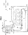
- Fig. 5 shows a configuration in which a foil transfer device serving as an example of a layer transfer device is mounted on a color laser printer serving as an example of an image forming apparatus.
- a right side of Fig. 5 is set as “front”, a left side of Fig. 5 as “rear”, a front side of the paper surface of Fig. 5 as “left”, and a back side of the paper surface of Fig. 5 as “right”.
- Upper and lower sides of Fig. 5 are set as “upper” and “lower” respectively.
- a color laser printer 101 mainly includes a paper feeding unit 103 and an image forming unit 104 in a housing 102.
- a foil transfer device 120 serving as an optional product is mounted to an upper portion on a rear side of the housing 102.
- the foil transfer device 120 has a configuration similar to that of the foil transfer device 1 shown in Fig. 1 .
- the sheet S supplied from the paper feeding unit 103 is conveyed one by one to the image forming unit 104, and a toner image is formed on a front surface of the sheet S in the image forming unit 104.
- the sheet S on which the toner image is formed is conveyed to a fixing device 106, with its front surface being directed upward, and the toner image is thermally fixed to the sheet S when the sheet S passes the fixing device 106.
- the sheet S is discharged onto a first sheet discharge tray 110 through a first sheet discharge port 108 of the housing 102, in a state where the front surface on which the toner image is thermally fixed is directed downward.
- a flapper 112 is switched to a position indicated by a solid line, and the sheet S is guided toward the first sheet discharge port 108 by a front face of the flapper 112.
- the sheet S is conveyed toward the foil transfer device 120 by switching the position of the flapper 112 to a position indicated by a broken line.
- the sheet S having passed the fixing device 106 passes over a back face of the flapper 112, and passes the film transfer unit 50 of the foil transfer device 120 in a state where its front surface on which the toner image is thermally fixed is overlapped with the multilayer film F supplied from the supply reel 21.
- the toner image of the sheet S passes the pressing roller 51 and the heating roller 61 of the film transfer unit 50, the front surface on which the toner image is thermally fixed by the fixing device 106 melts and the foil is thermally transferred.
- the sheet S on which the foil is thermally transferred is conveyed toward the conveying rollers 18, and the multilayer film F after the foil being thermally transferred is wound around the wind-up reel 31 via the peeling roller 43.
- the sheet S is discharged onto a second sheet discharge tray 130 through a second sheet discharge port 128 by the pair of conveying rollers 18 and a pair of second conveying rollers 122 in a state where the front surface on which the foil is thermally fixed is directed downward.
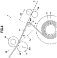
- the foil transfer device 120 can have a configuration similar to that of the foil transfer device shown in Fig. 4 without a holding member.
- the foil transfer device 120 of the color laser printer 101 According to the foil transfer device 120 of the color laser printer 101, the same effects as those of the foil transfer devices in the embodiments described above can be obtained.
- the film transfer unit 50 includes the pressing roller 51 as a first roller provided at a position to contact the sheet S and a heating roller 61 as a second roller provided at a position to contact the multilayer film F, and alternatively, the film transfer unit can be configured to include a heating roller as a first roller provided at a position to contact the sheet S and a pressing roller as a second roller provided at a position to contact the multilayer film F.
- a surface of the heating roller is recessed with respect to the pressing roller, and accordingly a nip part has a circular arc shape.
- a roller that sandwiches the sheet S and the multilayer film F with the peeling roller 43 can be provided instead of the holding member 45.
Landscapes
- Physics & Mathematics (AREA)
- General Physics & Mathematics (AREA)
- Engineering & Computer Science (AREA)
- Mechanical Engineering (AREA)
- Electrostatic Charge, Transfer And Separation In Electrography (AREA)
- Decoration By Transfer Pictures (AREA)
Abstract
Description
- The present invention relates to a layer transfer device that overlaps a multilayer film having a plurality of layers with a surface of a sheet on which a toner image is formed, and that transfers at least one layer of the multilayer film onto the toner image.
- In the related art, there is known a layer transfer device that includes a supply reel around which a multilayer film is wound and a wind-up reel that winds up the multilayer film from the supply reel. In a state where a sheet conveyed from a sheet conveying unit is overlapped with the multilayer film supplied from the supply reel, the layer transfer device transfers a transfer layer onto a toner image of the sheet (see, for example, Patent Literature 1).
- In such a layer transfer device, after the sheet and the multilayer film are caused to pass a nip part of a heating roller and a pressing roller and to perform thermal transfer in a state where the sheet and the multilayer film are overlapped each other, the sheet and the multilayer film are conveyed along a direction of a tangent line of the heating roller at a downstream end of the nip part in a conveying direction. Further, when the multilayer film passes a peeling roller provided on the tangent line of the heating roller, the multilayer film which has been thermal transferred is peeled off from the sheet and is wound by the wind-up reel.
- Patent Literature 1:
JP-A-S62-261463 - The sheet which passes the nip part of the heating roller and the pressing roller and which is conveyed in a tangent line direction tends to curl to conform to a shape of the heating roller. When the sheet curls, the sheet is to be partially peeled off from a contact surface shared with the multilayer film before reaching the peeling roller.
- When such a force is applied before the sheet reaches the peeling roller, the transfer layer which is softened due to heating in the vicinity of the toner image may be pulled by the sheet and adhere to the sheet. As a result, an excess transfer layer is transferred around the toner image, so that so-called burrs may be generated, the transfer layer may be excessively transferred with respect to the toner image, and the transfer layer may be insufficient with respect to the toner image.
- Therefore, an object of the present invention is to provide a layer transfer device capable of preventing action of a force of peeling a sheet from a multilayer film when the sheet passes from a nip part of a heating roller and a pressing roller to a peeling roller, and capable of transferring a transfer layer onto a toner image without causing excess or deficiency in a transfer portion.
- In order to solve the problems described above, the present invention provides a layer transfer device that overlaps a multilayer film having a plurality of layers with a surface of a sheet on which a toner image is formed, the layer transfer device being configured to transfer at least one layer of the multilayer film onto the toner image, the layer transfer device including: a sheet conveying unit configured to convey the sheet; a supply reel around which the multilayer film is wound; a wind-up reel configured to wind up the multilayer film from the supply reel; a film transfer unit configured to perform transfer in a state where the multilayer film supplied from the supply reel is overlapped with the sheet conveyed from the sheet conveying unit; and a peeling roller disposed between the film transfer unit and the wind-up reel in a conveyance path of the multilayer film, the peeling roller contacting the multilayer film having passed the film transfer unit, the peeling roller being configured to peel off the multilayer film from the sheet when a conveying direction of the multilayer film having passed the film transfer unit is changed to a direction different from a conveying direction of the sheet due to the wind-up reel winding up the multilayer film.
- The film transfer unit includes: a first roller provided at a position to contact the sheet; and a second roller provided at a position to contact the multilayer film, and the film transfer unit overlaps the sheet with the multilayer film and is configured to heat and press the sheet and the multilayer film at a nip part of the first roller and the second roller.
- Further, a tangent line of the second roller at a downstream end of the nip part in the conveying direction of the sheet passes between a center of the second roller and a center of the peeling roller, and an angle formed by the tangent line and a film tension portion of the multilayer film tensed between the nip part and the peeling roller is 15 degrees to 37 degrees.
- According to this configuration, since the tangent line of the second roller passes between the center of the second roller and the center of the peeling roller and the angle formed by the tangent line and the film tension portion is 15 degrees to 37 degrees, the sheet that is heated and pressed at the nip part of the first roller and the second roller and that curls along the shape of the second roller can be corrected by the multilayer film in the vicinity of an exit of the nip part.
- Therefore, when moving from the nip part to the peeling roller, the sheet overlapped with the multilayer film is in close contact with the multilayer film and the peeling is not performed, and after the transfer layer thermally transferred at the nip part is sufficiently cooled, the multilayer film is peeled off from the sheet by the peeling roller. Therefore, image quality that edges are sharp and that burrs are few in a transfer portion can be obtained. In other words, a foil is transferred to a portion on the sheet where the toner image is formed and the foil is not transferred to a portion on the sheet where the toner image is not formed, and accordingly there is no excess transfer layer on an edge portion of the toner image and a good image quality can be obtained.
- In the above-described layer transfer device, the first roller has lower hardness than the second roller, and since a surface of the first roller is recessed with respect to the second roller at the nip part so that the nip part can have a circular arc shape.
- Accordingly, since the nip part is formed in the circular arc shape, the conveyance path of the sheet can be made in a curved shape. Therefore, since members close to the first roller and the second roller can be laid out in proximity to the first roller and the second roller, a size of the layer transfer device can be reduced.
- For example, in the above-described layer transfer device, the first roller has a rubber layer on the surface of the first roller and the second roller is a rigid body having no rubber layer, and the rubber layer of the first roller can have JIS-A hardness of 20° to 60°. Alternatively, each of the first roller and the second roller has a rubber layer on respective surfaces, the rubber layer of the first roller has JIS-A hardness of 20° to 60°, and the rubber layer of the second roller can have JIS-A hardness of 5° to 30°.
- The rubber layer can be made of silicone rubber.
- In the above-described layer transfer device, the angle formed by the tangent line and the film tension portion can be 23.2 degrees to 28.2 degrees.
- Accordingly, image quality that edges are cleaner in the transfer portion can be obtained.
- In the above-described layer transfer device, the first roller is a pressing roller, and the second roller can be a heating roller.
- Further, the pressing roller is driven, and the heating roller can be rotated by rotation of the pressing roller.
- In the above-described layer transfer device, a pair of conveying rollers configured to convey the sheet can be arranged downstream of the peeling roller, and a peripheral speed of the conveying roller can be made greater than a peripheral speed of the first roller.
- Accordingly, since the sheet can be conveyed in a state where tension is applied to the sheet between the nip part of the first roller and the second roller and a nip part of the conveying rollers, the multilayer film can be peeled off cleanly at the time of peeling by the peeling roller. As a result, image quality that the edges are cleaner in the transfer portion can be obtained.
- In order to solve the problems described above, the present invention provides an image forming apparatus including: the above-described layer transfer device, and an image forming unit configured to form the toner image on the sheet.
- The layer transfer device includes a holding member sandwiching the sheet and the multilayer film with the peeling roller, and a distance from the holding member to the nip part of the conveying rollers is equal to or larger than a distance from a leading end of the sheet to a leading end of a range where the image forming unit is capable of forming the toner image on the sheet.
- Accordingly, by providing the holding member that sandwiches the sheet and the multilayer film with the peeling roller, the leading end of the sheet from which the multilayer film is peeled off by passing the peeling roller can be prevented from floating in a direction of separating from the peeling roller, and vibration of the sheet due to the peeling can be suppressed.
- Further, since the conveying roller can be spaced apart by a distance equal to or larger than the distance (leading end margin length) from the leading end of the sheet to be conveyed to a range (image forming region) where the image forming part is capable of forming the toner image on the sheet, the degree of freedom of the layout of the layer transfer device can be increased.
- In order to solve the problems described above, the present invention provides an image forming apparatus including: the above-described layer transfer device, and an image forming part unit configured to form the toner image on the sheet.
- In the layer transfer device, a distance from the peeling roller to the nip part of the conveying rollers is less than the distance from the leading end of the sheet to the leading end of the range where the image forming unit is capable of forming the toner image on the sheet.
- Accordingly, since the distance from the peeling roller to the nip part of the conveying roller is less than the leading end margin length of the sheet, the multilayer film is peeled off from the image forming region of the sheet after the leading end of the sheet is nipped by the nip portion of the conveying rollers. Therefore, image quality that the edges are cleaner can be obtained.
- According to the present invention, action of a force of peeling a sheet from a multilayer film when the sheet passes from a nip part of a heating roller and a pressing roller to a peeling roller can be prevented, and a transfer layer can be transferred onto a toner image without causing excess or deficiency in a transfer portion.
-
-
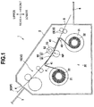
Fig. 1 is a cross-sectional view of a foil transfer device according to an embodiment. -
Fig. 2 is an enlarged view of a main part of the foil transfer device ofFig. 1 , illustrating a peripheral structure of a heating roller and a pressing roller. -
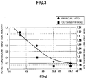
Fig. 3 is a graph showing results of an experiment conducted using the foil transfer device. -
Fig. 4 is an illustrative view of a foil transfer device according to a modification. -
Fig. 5 is a cross-sectional view of a laser printer to which the foil transfer device as an optional product is mounted. - Embodiments of the present invention will be described in detail with reference to an appropriate drawing. In the following description, first, an entire configuration of a foil transfer device is briefly described, and thereafter a peripheral structure of a heating roller and a pressing roller will be described.
- In the following description, directions will be described with directions shown in
Fig. 1 . That is, a right side ofFig. 1 is set as "front", a left side ofFig. 1 as "rear", a front side of a paper surface ofFig. 1 as "left", and a back side of the paper surface ofFig. 1 as "right". Upper and lower sides ofFig. 1 are set as "upper" and "lower" respectively. - A
foil transfer device 1 as an example of a layer transfer device is, for example, a device that, after an image forming apparatus such as a laser printer forms a toner image on a sheet, transfers a foil such as a gold foil onto the toner image of the sheet. - As shown in
Fig. 1 , thefoil transfer device 1 includes amain body housing 2, a sheet tray 3 that is provided at a rear portion of themain body housing 2 and on which a sheet S such as a piece of paper or an OHP film is placed, asheet supply port 4 through which the sheet S supplied from the sheet tray 3 passes, asheet discharge port 5 that is provided at a front portion of themain body housing 2, and a sheet discharge tray 6 on which the sheet S discharged through thesheet discharge port 5 is placed. - The
main body housing 2 mainly includes, in an inner portion thereof, asheet conveying unit 10 that conveys the sheet S along a conveyance path SP extending from thesheet supply port 4 to thesheet discharge port 5, afilm supply unit 20 that supplies a multilayer film F so as to overlap the multilayer film F with the sheet S conveyed from thesheet conveying unit 10, and afilm transfer unit 50 that heats and presses the sheet S and the multilayer film F in a state where the sheet S and the multilayer film F are overlapped each other. - The
sheet conveying unit 10 mainly includes asheet supply mechanism 15 that includes a plurality of pairs of rollers and that conveys the sheet S supplied through thesheet supply port 4 toward thefilm transfer unit 50, and a pair ofconveying rollers 18 that conveys the sheet S which has passed thefilm transfer unit 50 toward thesheet discharge port 5. - The
sheet conveying unit 10 conveys the sheet S placed on the sheet tray 3 one by one toward thefilm transfer unit 50 by thesheet supply mechanism 15 in a state where a surface (front surface) of the sheet S on which the toner image is formed is directed downward. Thesheet conveying unit 10 guides the sheet S which passes thefilm transfer unit 50 and on which a foil is transferred toward thesheet discharge port 5 by theconveying rollers 18. - The
film supply unit 20 includes the multilayer film F, asupply reel 21, a wind-up reel 31, asupport roller 41, apeeling roller 43, and aholding member 45. - The multilayer film F has, on a tape-like support layer made of a polymer material, a release layer and a foil layer that serves as a transfer layer. The foil is a thin metal such as gold, silver, copper, or aluminum.
- The multilayer film F is mainly made of a polymer material.
- The
supply reel 21 includes arotatable supply shaft 22, and the multilayer film F is wound around thesupply shaft 22. - The wind-
up reel 31 includes a rotatable wind-upshaft 32, and a leading end of the multilayer film F is fixed to the wind-upshaft 32. - The wind-
up reel 31 is rotationally driven by a drive part (not shown) provided in themain body housing 2. When the wind-up reel 31 rotates, the multilayer film F wound around thesupply reel 21 is drawn out, and the drawn-out multilayer film F is wound around the wind-upshaft 32. - The
support roller 41 is disposed downstream of thesheet supply mechanism 15 in a conveying direction of the sheet S and below the conveyance path SP of the sheet S. More specifically, in a conveyance path of the multilayer film F, thesupport roller 41 is disposed upstream of thefilm transfer unit 50 and between thesupply reel 21 and the wind-up reel 31. - The
support roller 41 is a roller that guides the multilayer film F supplied from thesupply reel 21 with the transfer layer directed upward so as to overlap with the sheet S conveyed from thesheet supply mechanism 15 with the toner image directed downward. Thesupport roller 41 changes a conveying direction of the multilayer film F drawn out from thesupply reel 21 and guides the multilayer film F to be substantially parallel to the conveyance path SP of the sheet S. - The peeling
roller 43 is disposed downstream of thefilm transfer unit 50 in the conveying direction of the sheet S and below the conveyance path SP of the sheet S. More specifically, in the conveyance path of the multilayer film F, the peelingroller 43 is disposed downstream of thefilm transfer unit 50 and between thesupply reel 21 and the wind-up reel 31. The peelingroller 43 is a roller that contacts the multilayer film F having passed thefilm transfer unit 50, and that changes the conveying direction of the multilayer film F having passed thefilm transfer unit 50 to a direction different from the conveyance path SP of the sheet S due to the wind-up reel 31 winding up the multilayer film F. - The multilayer film F which passes the
film transfer unit 50 and which is conveyed in a state of being overlapped with the sheet S is guided in a direction different from a direction of the sheet S when passing the peelingroller 43, and is peeled off from the sheet S. - The holding
member 45 is disposed downstream of thefilm transfer unit 50 in the conveying direction of the sheet S and at a position facing the peelingroller 43 above the conveyance path SP of the sheet S. - The holding
member 45 sandwiches the sheet S and the multilayer film F with the peelingroller 43. - The
film transfer unit 50 includes apressing roller 51 serving as an example of a first roller and aheating roller 61 serving as an example of a second roller. Thefilm transfer unit 50 overlaps the sheet S and the multilayer film F with each other, and heats and presses the sheet S and the multilayer film F at a nip part NP of thepressing roller 51 and theheating roller 61. - The
pressing roller 51 is disposed above the conveyance path SP of the sheet S and at a position to contact a back surface of the sheet S (a surface opposite the surface formed with the toner image). - The
pressing roller 51 is a roller in which acylindrical core metal 52 provided at a center portion thereof is covered with arubber layer 53 made of silicone rubber. Therubber layer 53 has JIS-A hardness of 20° to 60°, and a thickness of therubber layer 53 is 3.0 mm to 8.0 mm. Thepressing roller 51 has a diameter of 20 mm to 40 mm. The JIS-A hardness conforms to ISO 7619-2004. - Both end portions of the
pressing roller 51 are rotatably supported by themain body housing 2, and thepressing roller 51 is rotationally driven by a motor (not shown). When thepressing roller 51 is pressed against theheating roller 61, the sheet S and the multilayer film F are held between thepressing roller 51 and theheating roller 61, and theheating roller 61 is rotated by rotation of thepressing roller 51. - The
heating roller 61 is disposed below the conveyance path SP of the sheet S and at a position to contact the multilayer film F. - The
heating roller 61 is a roller in which a heater (not shown) is disposed inside a metal tube formed in a cylindrical shape. Theheating roller 61 has a diameter of 20 mm to 40 mm. Theheating roller 61 is a rigid body having no rubber layer. - The
pressing roller 51 has lower hardness than theheating roller 61, and in a state where thepressing roller 51 is pressed against theheating roller 61, a surface of thepressing roller 51 is recessed with respect to theheating roller 61. Therefore, the nip part NP of thepressing roller 51 and theheating roller 61 has a circular arc shape by the recessed pressingroller 51. - A rubber layer made of silicone rubber can be provided on a surface of the
heating roller 61. In this case, therubber layer 53 of thepressing roller 51 has JIS-A hardness of 20° to 60° and the rubber layer of theheating roller 61 has JIS-A hardness of 5° to 30°, so that the hardness of thepressing roller 51 is relatively lower than the hardness of theheating roller 61. - A thickness of the rubber layer of the
heating roller 61 and the thickness of therubber layer 53 of thepressing roller 51 are 3.0 mm to 8.0 mm. - In the
foil transfer device 1 configured as described above, the sheet S which is placed on the sheet tray 3 with the front surface thereof directed downward is conveyed one by one toward thefilm transfer unit 50 by thesheet supply mechanism 15. - Upstream the
film transfer unit 50, the sheet S conveyed along the conveyance path SP of the sheet S is overlapped with the multilayer film F supplied from thesupply reel 21 along the conveyance path of the multilayer film F, and is conveyed to thefilm transfer unit 50 in a state where the toner image of the sheet S and the transfer layer of the multilayer film F are in contact with each other. - In the
film transfer unit 50, when the sheet S and the multilayer film F pass the nip part NP of thepressing roller 51 and theheating roller 61, the sheet S and the multilayer film F are heated and pressed by theheating roller 61 and thepressing roller 51, and the foil is thermally transferred onto the toner image. - After the foil is thermally transferred, the sheet S and the multilayer film F are conveyed to the peeling
roller 43 in a state of being in close contact with each other. When the sheet S and the multilayer film F pass the peelingroller 43, the conveying direction of the multilayer film F is changed to a direction different from the conveying direction of the sheet S, and thus the multilayer film F is peeled off from the sheet S. - The multilayer film F peeled off from the sheet S is wound around the wind-up
shaft 32 of the wind-up reel 31. Meanwhile, the sheet S from which the multilayer film F is peeled off is conveyed toward a nip part of the conveyingrollers 18. - Further, the sheet S having passed the conveying
rollers 18 is discharged from thesheet discharge port 5 to thesheet discharge tray 6 in a state where the front surface on which the foil is transferred is directed downward. - Next, a configuration on a downstream side of the
film transfer unit 50 will be described, which is a characteristic of the present invention. - As shown in
Fig. 2 , the peelingroller 43 is disposed upward than a tangent line TL passing through the nip part NP of thepressing roller 51 and theheating roller 61. More specifically, the tangent line TL of theheating roller 61 at a downstream end of the nip part NP of thepressing roller 51 and theheating roller 61 in the conveying direction of the sheet S passes between arotation center 61A of theheating roller 61 and arotation center 43A of the peelingroller 43. - Further, a film tension portion FT of the multilayer film F conveyed along the conveyance path of the multilayer film F is tensed between the nip part NP and the peeling
roller 43, and forms an angle θ with the tangent line TL. The angle θ formed by the tangent line TL and the film tension portion FT is set within a predetermined range. - the peeling
roller 43 is disposed such that the film tension portion FT is located upward than the tangent line TL, so that the sheet S, which passes the nip part NP of thepressing roller 51 and theheating roller 61 and is heated and pressed and is about to curl along a shape of theheating roller 61, can be corrected by the multilayer film F in the vicinity of an exit of the nip part NP. - The holding
member 45 sandwiches the sheet S, of which the curl is corrected, with the film tension portion FT and guides the sheet S. The sheet S and the multilayer film F which are in close contact with each other after passing thefilm transfer unit 50 are guided along the holdingmember 45, and thus are conveyed to the peelingroller 43 in a state of being in close contact with each other without occurrence that a force acts to peel off the sheet S from the multilayer film F before the sheet S reaches the peelingroller 43; meanwhile, the transfer layer softened by heating is sufficiently cooled. - The holding
member 45 prevents the leading end of the sheet S, from which the multilayer film F is peeled off by passing the peelingroller 43, from floating in a direction of separating from the peelingroller 43, and also plays a role of suppressing vibration of the sheet S caused by the peeling. - The conveying
rollers 18 rotate at a peripheral speed larger than a peripheral speed of thepressing roller 51. - The conveying
rollers 18 can be disposed at a position such that a distance from the holdingmember 45 to the nip part of the conveyingrollers 18 is equal to or larger than a distance (hereinafter, referred to as "leading end margin length") from the leading end of the sheet S to be conveyed to a leading end of a range (image forming region) where an image forming apparatus is capable of forming the toner image on the sheet S. More specifically, the conveyingrollers 18 can be spaced apart from the peelingroller 43 such that a distance D1 from a position, where the sheet S and the multilayer film F are sandwiched by a leading end portion of the holdingmember 45 and the peelingroller 43, to the nip part of the conveyingrollers 18 is equal to or larger than the leading end margin length of the sheet S. - In the
foil transfer device 1 configured as described above, the curl of the sheet S having passed thefilm transfer unit 50 is corrected in the vicinity of the exit of the nip part NP of thepressing roller 51 and theheating roller 61, and thereafter the sheet S is guided by the film tension portion FT and the holdingmember 45 and is conveyed in a state of being in close contact with the multilayer film F. Therefore, a force acts to peel off the sheet S from the multilayer film F before the sheet S reaches the peelingroller 43, and while the sheet S moves from the nip part NP to the peelingroller 43, the transfer layer of the multilayer film F is sufficiently cooled in a state of being in close contact with the toner image of the sheet S. Accordingly, the foil can be reliably transferred onto the toner image. - Thereafter, the leading end of the sheet S from which the multilayer film F is peeled off by passing the peeling
roller 43 is conveyed toward the nip part of the conveyingrollers 18. - Further, since the peripheral speed of the conveying
roller 18 is larger than the peripheral speed of thepressing roller 51, the sheet S of which the leading end reaches the conveyingroller 18 is conveyed in a state where tension is applied to the sheet S between the nip part NP and the nip part of the conveyingrollers 18. Meanwhile, since the multilayer film F which passes the peelingroller 43 and which is to be peeled off from the sheet S is peeled off from the sheet S that is in a state where tension is applied to the sheet S, the multilayer film F can be peeled off cleanly. - Next, a reason for determining the predetermined range of the angle θ formed by the film tension portion FT and the tangent line TL (experimental result) will be described.
- The inventors of the present application conducted an experiment in which an angle θ, which is formed by a tangent line of a heating roller at a downstream end of a nip part of a pressing roller and the heating roller in a conveying direction of paper and a film tension portion of a multilayer film tensed between the nip part and a peeling roller, was variously changed to determine an angle range of θ at which generation of burrs in a transfer portion could be prevented and good image quality could be obtained.
- Paper used in the experiment was Neenah Paper Exact Index (manufactured by Neenah Paper) with a basis weight of 199 g/m2. In a foil transfer device used in the experiment, diameters of a pressing roller and a heating roller are both 25 mm, and a thickness of a rubber layer of the pressing roller is 5.5 mm. Measurement was performed in an environment with a temperature of 25 °C and a humidity of 30 %.
- Specifically, a curl amount (input curl amount) of the paper at a time when a toner image was formed by a laser printer was measured, and then another curl amount (output curl amount) of the paper after a foil was transferred thereto by the foil transfer device was measured. Further, a paper curl ratio defined by output curl amount/input curl amount was determined.
- When the paper curl ratio is larger than 1, it means that the curl amount of the paper is increased after the paper passes the film transfer unit of the foil transfer device.
- The measurement of the curl amount was performed as follows:
- (1) Wait for 1 minute after feeding the paper.
- (2) Place the paper on a horizontal table and bring a center of the paper into contact with the table so that four corners of the paper float from the table.
- (3) Use a ruler to measure a distance from the corner of the paper to the horizontal table for all four corners.
- (4) Repeat (1) to (3) for 3 sheets of paper.
- (5) Calculate an average value of the distances from the corners of the paper to the horizontal table, that is, an average value for 4 (points) × 3 (sheets) = 12 (points).
- (6) Repeat (1) to (5) for each angle θ.
- In addition, for paper on which a toner image was formed by the laser printer, area of the toner image was measured as pre-print area, and area of the foil transferred onto the toner image by the foil transfer device was measured as foil transfer area. Further, a foil transfer ratio defined by foil transfer area/pre-print area was calculated.
- When the foil transfer ratio is large, it means that the area of the foil transferred is larger with respect to the area of the toner image. That is, an excess foil is transferred around the toner image, indicating that a so-called burr has occurred. The foil transfer ratio being at a value close to 1 means image quality that there are few burrs and that edges are sharp in a transfer portion.
- The paper curl ratio and the foil transfer ratio described above were determined while changing the angle θ formed by the tangent line and the film tension portion.
Fig. 3 is a graph in which the output curl amount/input curl amount is taken on a vertical axis, the angle θ formed by the tangent line and the film tension portion is taken on a horizontal axis, and the paper curl ratio and the foil transfer ratio are plotted. - As a limit of the configuration of the foil transfer device, θ needs to be set to 37 degrees or less.
- Referring to
Fig. 3 , it was confirmed that, with the angle θ formed by the tangent line and the film tension portion being at 15 degrees or more, the paper curl ratio was 1 or less and the value of the foil transfer ratio also fell within an allowable range. - Further, it was confirmed that, with θ being in a range of 23.2 degrees to 28.2 degrees, the paper curl ratio was sufficiently small and the curl of the paper was greatly corrected. At this time, the value of the foil transfer ratio was also 1.16 or less, and image quality that there were few burrs and that edges were sharp in the transfer portion could be obtained.
- The paper used in the foil transfer device is preferably thick paper such as the above-described Neenah Paper Exact Index (manufactured by Neenah Paper) with a basis weight of 199 g/m2 or Mondi Color Copy (manufactured by Mondi) with a basis weight of 300 g/m2.
- According to the above, the following effects can be obtained in the present embodiment.
- When the peeling
roller 43 is disposed such that the tangent line TL of theheating roller 61 passes between therotation center 61A of theheating roller 61 and therotation center 43A of the peelingroller 43, and the angle formed by the tangent line TL and the film tension portion FT is 15 degrees to 37 degrees, the sheet S which is heated and pressed at the nip part NP of thepressing roller 51 and theheating roller 61 and which is about to curl along the shape of theheating roller 61 can be corrected by the film tension portion FT in the vicinity of the exit of the nip part NP. - Therefore, when moving from the nip part NP to the peeling
roller 43, the sheet S overlapped with the multilayer film F is in close contact with the multilayer film F and the peeling is not performed, and after the foil thermally transferred at the nip part NP is sufficiently cooled, the multilayer film F is peeled off from the sheet S by the peelingroller 43. Therefore, image quality that edges are sharp and that burrs are few in a transfer portion can be obtained. In other words, the foil is transferred to a portion on the sheet S where the toner image is formed and the foil is not transferred to a portion on the sheet S where the toner image is not formed, and accordingly there is no excess transfer layer on the edge portion of the toner image and a good image quality can be obtained. - Further, when the angle formed by the tangent line TL and the film tension portion FT is 23.2 degrees to 28.2 degrees, image quality that edges are cleaner in the transfer portion can be obtained.
- The
pressing roller 51 has lower hardness than theheating roller 61, and the surface of thepressing roller 51 is recessed with respect to theheating roller 61 in the nip part NP so that the nip part NP has a circular arc shape. Accordingly, the conveyance path SP of the sheet S can be curved. Therefore, members close to thepressing roller 51 and theheating roller 61 can be laid out in proximity to thepressing roller 51 and theheating roller 61, and thus a size of thefoil transfer device 1 can be reduced. - Since the pair of conveying
rollers 18 that convey the sheet S is disposed downstream of the peelingroller 43 in the conveying direction of the sheet S and the peripheral speed of the conveyingrollers 18 is larger than the peripheral speed of thepressing roller 51, the sheet S can be conveyed in a state where tension is applied to the sheet S between the nip part NP and the nip part of the conveyingrollers 18. Therefore, at the time of peeling the multilayer film F off from the sheet S by the peelingroller 43, the peeling can be performed cleanly. As a result, image quality that the edges are cleaner in the transfer portion can be obtained. - By providing the holding
member 45 which sandwiches the sheet S and the multilayer film F with the peelingroller 43, the leading end of the sheet S from which the multilayer film F has been peeled by passing the peelingroller 43 can be prevented from floating in a direction away from the peelingroller 43, and vibration of the sheet S due to peeling can be suppressed. - Further, since the conveying
roller 18 can be disposed at a position spaced apart by a distance equal to or larger than the leading end margin length of the sheet S to be conveyed, the degree of freedom in the layout of thefoil transfer device 1 can be increased. - Next, a second embodiment of the present invention will be described.
- In the following description, the same components as those of the above-described embodiment are denoted by the same reference numerals, and a detailed description thereof is omitted.
- As shown in
Fig. 4 , in thefoil transfer device 1 according to a second embodiment, the holding member is not provided at a position facing the peelingroller 43, and a distance D2 from the peelingroller 43 to the nip part of the conveyingrollers 18 is less than the leading end margin length of the sheet S. - According to such a foil transfer device, since the distance D2 from the peeling
roller 43 to the nip part of the conveyingrollers 18 is less than the leading end margin length of the sheet, the multilayer film F is peeled off from the image forming region of the sheet S after the leading end of the sheet S is nipped by the nip part of the conveyingrollers 18. Therefore, image quality that the edges are cleaner can be obtained. - Although the embodiments of the present invention have been described above, the present invention is not limited to these embodiments. The specific configurations may be appropriately modified without departing from the spirit of the present invention.
- For example, although the foil transfer device has been described as a stand-alone device in the embodiments described above, the foil transfer device can be configured as an optional product of an image forming apparatus, or can be configured as a foil transfer unit attached to the image forming apparatus.
-
Fig. 5 shows a configuration in which a foil transfer device serving as an example of a layer transfer device is mounted on a color laser printer serving as an example of an image forming apparatus. - In the following description, directions will be described with directions shown in
Fig. 5 . That is, a right side ofFig. 5 is set as "front", a left side ofFig. 5 as "rear", a front side of the paper surface ofFig. 5 as "left", and a back side of the paper surface ofFig. 5 as "right". Upper and lower sides ofFig. 5 are set as "upper" and "lower" respectively. - As shown in
Fig. 5 , acolor laser printer 101 mainly includes apaper feeding unit 103 and animage forming unit 104 in ahousing 102. Afoil transfer device 120 serving as an optional product is mounted to an upper portion on a rear side of thehousing 102. - The
foil transfer device 120 has a configuration similar to that of thefoil transfer device 1 shown inFig. 1 . - In the
color laser printer 101, the sheet S supplied from thepaper feeding unit 103 is conveyed one by one to theimage forming unit 104, and a toner image is formed on a front surface of the sheet S in theimage forming unit 104. The sheet S on which the toner image is formed is conveyed to afixing device 106, with its front surface being directed upward, and the toner image is thermally fixed to the sheet S when the sheet S passes the fixingdevice 106. Thereafter, the sheet S is discharged onto a firstsheet discharge tray 110 through a firstsheet discharge port 108 of thehousing 102, in a state where the front surface on which the toner image is thermally fixed is directed downward. - At this time, a
flapper 112 is switched to a position indicated by a solid line, and the sheet S is guided toward the firstsheet discharge port 108 by a front face of theflapper 112. - When a foil is transferred to the toner image of the sheet S, the sheet S is conveyed toward the
foil transfer device 120 by switching the position of theflapper 112 to a position indicated by a broken line. - The sheet S having passed the
fixing device 106 passes over a back face of theflapper 112, and passes thefilm transfer unit 50 of thefoil transfer device 120 in a state where its front surface on which the toner image is thermally fixed is overlapped with the multilayer film F supplied from thesupply reel 21. When the toner image of the sheet S passes thepressing roller 51 and theheating roller 61 of thefilm transfer unit 50, the front surface on which the toner image is thermally fixed by the fixingdevice 106 melts and the foil is thermally transferred. - The sheet S on which the foil is thermally transferred is conveyed toward the conveying
rollers 18, and the multilayer film F after the foil being thermally transferred is wound around the wind-up reel 31 via the peelingroller 43. - Thereafter, the sheet S is discharged onto a second
sheet discharge tray 130 through a secondsheet discharge port 128 by the pair of conveyingrollers 18 and a pair of second conveyingrollers 122 in a state where the front surface on which the foil is thermally fixed is directed downward. - The
foil transfer device 120 can have a configuration similar to that of the foil transfer device shown inFig. 4 without a holding member. - According to the
foil transfer device 120 of thecolor laser printer 101, the same effects as those of the foil transfer devices in the embodiments described above can be obtained. - In the above-described embodiments and modification, the
film transfer unit 50 includes thepressing roller 51 as a first roller provided at a position to contact the sheet S and aheating roller 61 as a second roller provided at a position to contact the multilayer film F, and alternatively, the film transfer unit can be configured to include a heating roller as a first roller provided at a position to contact the sheet S and a pressing roller as a second roller provided at a position to contact the multilayer film F. - In this configuration, when the heating roller has lower hardness than the pressing roller and is pressed against the pressing roller, a surface of the heating roller is recessed with respect to the pressing roller, and accordingly a nip part has a circular arc shape.
- In addition, in the above-described embodiment, instead of the holding
member 45, a roller that sandwiches the sheet S and the multilayer film F with the peelingroller 43 can be provided. - Elements described in the embodiments and the modification described above can be optionally combined and implemented.
-
- S
- sheet
- F
- multilayer film
- 1
- foil transfer device
- 10
- sheet conveying unit
- 21
- supply reel
- 31
- wind-up reel
- 43
- peeling roller
- 43A
- rotation center (of peeling roller)
- 50
- film transfer unit
- 51
- pressing roller
- 61
- heating roller
- 61
- rotation center (of heating roller)
- NP
- nip part
- TL
- tangent line
- FT
- film tension portion
Claims (11)
- A layer transfer device that overlaps a multilayer film having a plurality of layers with a surface of a sheet on which a toner image is formed, the layer transfer device being configured to transfer at least one layer of the multilayer film onto the toner image, the layer transfer device comprising:a sheet conveying unit configured to convey the sheet;a supply reel around which the multilayer film is wound;a wind-up reel configured to wind up the multilayer film from the supply reel;a film transfer unit configured to perform transfer in a state where the multilayer film supplied from the supply reel is overlapped with the sheet conveyed from the sheet conveying unit; anda peeling roller disposed between the film transfer unit and the wind-up reel in a conveyance path of the multilayer film, the peeling roller contacting the multilayer film having passed the film transfer unit, the peeling roller being configured to peel off the multilayer film from the sheet when a conveying direction of the multilayer film having passed the film transfer unit is changed to a direction different from a conveying direction of the sheet due to the wind-up reel winding up the multilayer film,wherein the film transfer unit includes: a first roller provided at a position to contact the sheet; and a second roller provided at a position to contact the multilayer film, and the film transfer unit overlaps the sheet with the multilayer film and is configured to heat and press the sheet and the multilayer film at a nip part of the first roller and the second roller, andwherein a tangent line of the second roller at a downstream end of the nip part in the conveying direction of the sheet passes between a center of the second roller and a center of the peeling roller, and an angle formed by the tangent line and a film tension portion of the multilayer film tensed between the nip part and the peeling roller is 15 degrees to 37 degrees.
- The layer transfer device according to claim 1,
wherein the first roller has lower hardness than the second roller, and
wherein a surface of the first roller is recessed with respect to the second roller at the nip part so that the nip part has a circular arc shape. - The layer transfer device according to claim 2,
wherein the first roller has a rubber layer on the surface of the first roller, and the second roller is a rigid body having no rubber layer, and
wherein the rubber layer of the first roller has JIS-A hardness of 20° to 60°. - The layer transfer device according to claim 2,
wherein each of the first roller and the second roller has a rubber layer on respective surfaces,
wherein the rubber layer of the first roller has JIS-A hardness of 20° to 60°, and
wherein the rubber layer of the second roller has JIS-A hardness of 5° to 30°. - The layer transfer device according to claim 3 or 4,
wherein the rubber layer is made of silicone rubber. - The layer transfer device according to any one of claims 1 to 5,
wherein the angle formed by the tangent line and the film tension portion is 23.2 degrees to 28.2 degrees. - The layer transfer device according to any one of claims 1 to 6,
wherein the first roller is a pressing roller, and
wherein the second roller is a heating roller. - The layer transfer device according to any one of claims 1 to 7,
wherein the pressing roller is configured to be driven, and
wherein the heating roller is configured to be rotated by rotation of the pressing roller. - The layer transfer device according to any one of claims 1 to 8,
wherein a pair of conveying rollers configured to convey the sheet is disposed downstream of the peeling roller, and
wherein a peripheral speed of the conveying rollers is larger than a peripheral speed of the first roller. - An image forming apparatus comprising:the layer transfer device according to claim 9; andan image forming unit configured to form the toner image on the sheet,wherein the layer transfer device includes a holding member sandwiching the sheet and the multilayer film with the peeling roller, andwherein a distance from the holding member to a nip part of the conveying rollers is equal to or larger than a distance from a leading end of the sheet to a leading end of a range where the image forming unit is capable of forming the toner image on the sheet.
- An image forming apparatus comprising:the layer transfer device according to claim 9; andan image forming unit configured to form the toner image on the sheet,wherein a distance from the peeling roller to a nip part of the conveying rollers is less than a distance from a leading end of the sheet to a leading end of a range where the image forming unit is capable of forming the toner image on the sheet.
Applications Claiming Priority (2)
| Application Number | Priority Date | Filing Date | Title |
|---|---|---|---|
| JP2018061696 | 2018-03-28 | ||
| PCT/JP2019/012036 WO2019188761A1 (en) | 2018-03-28 | 2019-03-22 | Layer transfer device |
Publications (3)
| Publication Number | Publication Date |
|---|---|
| EP3778459A1 true EP3778459A1 (en) | 2021-02-17 |
| EP3778459A4 EP3778459A4 (en) | 2021-11-24 |
| EP3778459B1 EP3778459B1 (en) | 2025-04-09 |
Family
ID=68061679
Family Applications (1)
| Application Number | Title | Priority Date | Filing Date |
|---|---|---|---|
| EP19777786.5A Active EP3778459B1 (en) | 2018-03-28 | 2019-03-22 | Layer transfer device |
Country Status (4)
| Country | Link |
|---|---|
| US (1) | US11199802B2 (en) |
| EP (1) | EP3778459B1 (en) |
| CN (1) | CN111902352B (en) |
| WO (1) | WO2019188761A1 (en) |
Families Citing this family (3)
| Publication number | Priority date | Publication date | Assignee | Title |
|---|---|---|---|---|
| JP7512651B2 (en) * | 2020-04-01 | 2024-07-09 | ブラザー工業株式会社 | Image forming device |
| CN113978865B (en) * | 2021-09-18 | 2023-05-16 | 山东拜罗智能科技有限公司 | Separator and separating method for self-adhesive paper |
| JP2024161648A (en) * | 2023-05-08 | 2024-11-20 | ブラザー工業株式会社 | Foil transfer device |
Family Cites Families (9)
| Publication number | Priority date | Publication date | Assignee | Title |
|---|---|---|---|---|
| JPS62261463A (en) | 1986-05-09 | 1987-11-13 | Canon Inc | Recorder |
| US20100212821A1 (en) * | 2007-09-24 | 2010-08-26 | Scodix, Ltd. | System and method for cold foil relief production |
| US8417171B2 (en) * | 2008-10-24 | 2013-04-09 | Eastman Kodak Company | Method and apparatus for printing embossed reflective images |
| JP5906791B2 (en) * | 2011-03-31 | 2016-04-20 | コニカミノルタ株式会社 | Image forming method |
| JP5817492B2 (en) * | 2011-12-12 | 2015-11-18 | コニカミノルタ株式会社 | Foil image forming method and foil image forming apparatus |
| JP6000078B2 (en) * | 2012-11-09 | 2016-09-28 | ニスカ株式会社 | Transfer device |
| FR3033522B1 (en) * | 2015-03-12 | 2017-04-14 | Evolis | TREATMENT MACHINE WITH A ROLLING MODULE. |
| JP6599658B2 (en) * | 2015-06-19 | 2019-10-30 | キヤノンファインテックニスカ株式会社 | Transfer device |
| JP2017223734A (en) * | 2016-06-13 | 2017-12-21 | コニカミノルタ株式会社 | Image forming apparatus and printing method |
-
2019
- 2019-03-22 EP EP19777786.5A patent/EP3778459B1/en active Active
- 2019-03-22 CN CN201980022015.9A patent/CN111902352B/en active Active
- 2019-03-22 WO PCT/JP2019/012036 patent/WO2019188761A1/en not_active Ceased
-
2020
- 2020-09-28 US US17/034,848 patent/US11199802B2/en active Active
Also Published As
| Publication number | Publication date |
|---|---|
| CN111902352A (en) | 2020-11-06 |
| CN111902352B (en) | 2022-06-24 |
| US20210011418A1 (en) | 2021-01-14 |
| WO2019188761A1 (en) | 2019-10-03 |
| EP3778459B1 (en) | 2025-04-09 |
| US11199802B2 (en) | 2021-12-14 |
| EP3778459A4 (en) | 2021-11-24 |
Similar Documents
| Publication | Publication Date | Title |
|---|---|---|
| US11199802B2 (en) | Layer transfer device | |
| JP6543980B2 (en) | Fixing exit guide plate, fixing device and image forming apparatus | |
| JP2020116856A (en) | Coating device and image forming system | |
| CN101192037B (en) | Fixing device, image forming device including same, and sheet processing device | |
| JP2004239937A (en) | Image forming apparatus | |
| CN107003636B (en) | Method for manufacturing release member | |
| JP2017062382A (en) | Image heating device | |
| JP2021049752A (en) | Layer transfer device | |
| JP7619004B2 (en) | Sheet supply device and foil transfer device | |
| JP4857708B2 (en) | Fixing apparatus and image forming apparatus | |
| JP4872225B2 (en) | Image fixing device | |
| JP7439620B2 (en) | foil transfer device | |
| US12448239B2 (en) | Sheet remover, conveying device, and image forming apparatus | |
| US12577077B2 (en) | Sheet remover, conveying device, and image forming apparatus | |
| JP2005247484A (en) | Dehumidifier for recording sheet | |
| JP2025103308A (en) | Foil transfer device | |
| JP2002287554A (en) | Fixing device | |
| JP2024158957A (en) | Foil transfer device | |
| JP2024161648A (en) | Foil transfer device | |
| JP2005096948A (en) | Method and device for dehumidifying recording paper sheet | |
| JP5582179B2 (en) | Bending correction device, film making device | |
| JP2024122660A (en) | Foil transfer device | |
| JP2024170010A (en) | Image forming system | |
| JP2012252129A (en) | Image heating device | |
| JP2004302349A (en) | Fixing device and image forming apparatus mounted with it |
Legal Events
| Date | Code | Title | Description |
|---|---|---|---|
| STAA | Information on the status of an ep patent application or granted ep patent |
Free format text: STATUS: THE INTERNATIONAL PUBLICATION HAS BEEN MADE |
|
| PUAI | Public reference made under article 153(3) epc to a published international application that has entered the european phase |
Free format text: ORIGINAL CODE: 0009012 |
|
| STAA | Information on the status of an ep patent application or granted ep patent |
Free format text: STATUS: REQUEST FOR EXAMINATION WAS MADE |
|
| 17P | Request for examination filed |
Effective date: 20200925 |
|
| AK | Designated contracting states |
Kind code of ref document: A1 Designated state(s): AL AT BE BG CH CY CZ DE DK EE ES FI FR GB GR HR HU IE IS IT LI LT LU LV MC MK MT NL NO PL PT RO RS SE SI SK SM TR |
|
| AX | Request for extension of the european patent |
Extension state: BA ME |
|
| DAV | Request for validation of the european patent (deleted) | ||
| DAX | Request for extension of the european patent (deleted) | ||
| REG | Reference to a national code |
Ref country code: DE Ref legal event code: R079 Free format text: PREVIOUS MAIN CLASS: B65H0041000000 Ipc: G03G0015000000 Ref country code: DE Ref legal event code: R079 Ref document number: 602019068447 Country of ref document: DE Free format text: PREVIOUS MAIN CLASS: B65H0041000000 Ipc: G03G0015000000 |
|
| A4 | Supplementary search report drawn up and despatched |
Effective date: 20211021 |
|
| RIC1 | Information provided on ipc code assigned before grant |
Ipc: B65H 37/04 20060101ALI20211015BHEP Ipc: B44C 1/17 20060101ALI20211015BHEP Ipc: B41F 16/00 20060101ALI20211015BHEP Ipc: B32B 37/00 20060101ALI20211015BHEP Ipc: B65H 5/06 20060101ALI20211015BHEP Ipc: B65H 41/00 20060101ALI20211015BHEP Ipc: G03G 15/22 20060101ALI20211015BHEP Ipc: G03G 15/20 20060101ALI20211015BHEP Ipc: G03G 15/00 20060101AFI20211015BHEP |
|
| P01 | Opt-out of the competence of the unified patent court (upc) registered |
Effective date: 20230529 |
|
| GRAP | Despatch of communication of intention to grant a patent |
Free format text: ORIGINAL CODE: EPIDOSNIGR1 |
|
| STAA | Information on the status of an ep patent application or granted ep patent |
Free format text: STATUS: GRANT OF PATENT IS INTENDED |
|
| INTG | Intention to grant announced |
Effective date: 20241031 |
|
| GRAS | Grant fee paid |
Free format text: ORIGINAL CODE: EPIDOSNIGR3 |
|
| GRAA | (expected) grant |
Free format text: ORIGINAL CODE: 0009210 |
|
| STAA | Information on the status of an ep patent application or granted ep patent |
Free format text: STATUS: THE PATENT HAS BEEN GRANTED |
|
| AK | Designated contracting states |
Kind code of ref document: B1 Designated state(s): AL AT BE BG CH CY CZ DE DK EE ES FI FR GB GR HR HU IE IS IT LI LT LU LV MC MK MT NL NO PL PT RO RS SE SI SK SM TR |
|
| REG | Reference to a national code |
Ref country code: GB Ref legal event code: FG4D |
|
| REG | Reference to a national code |
Ref country code: CH Ref legal event code: EP |
|
| REG | Reference to a national code |
Ref country code: DE Ref legal event code: R096 Ref document number: 602019068447 Country of ref document: DE |
|
| REG | Reference to a national code |
Ref country code: IE Ref legal event code: FG4D |
|
| REG | Reference to a national code |
Ref country code: NL Ref legal event code: MP Effective date: 20250409 |
|
| PG25 | Lapsed in a contracting state [announced via postgrant information from national office to epo] |
Ref country code: NL Free format text: LAPSE BECAUSE OF FAILURE TO SUBMIT A TRANSLATION OF THE DESCRIPTION OR TO PAY THE FEE WITHIN THE PRESCRIBED TIME-LIMIT Effective date: 20250409 |
|
| REG | Reference to a national code |
Ref country code: AT Ref legal event code: MK05 Ref document number: 1784058 Country of ref document: AT Kind code of ref document: T Effective date: 20250409 |
|
| PG25 | Lapsed in a contracting state [announced via postgrant information from national office to epo] |
Ref country code: FI Free format text: LAPSE BECAUSE OF FAILURE TO SUBMIT A TRANSLATION OF THE DESCRIPTION OR TO PAY THE FEE WITHIN THE PRESCRIBED TIME-LIMIT Effective date: 20250409 Ref country code: ES Free format text: LAPSE BECAUSE OF FAILURE TO SUBMIT A TRANSLATION OF THE DESCRIPTION OR TO PAY THE FEE WITHIN THE PRESCRIBED TIME-LIMIT Effective date: 20250409 Ref country code: PT Free format text: LAPSE BECAUSE OF FAILURE TO SUBMIT A TRANSLATION OF THE DESCRIPTION OR TO PAY THE FEE WITHIN THE PRESCRIBED TIME-LIMIT Effective date: 20250811 |
|
| REG | Reference to a national code |
Ref country code: LT Ref legal event code: MG9D |
|
| PG25 | Lapsed in a contracting state [announced via postgrant information from national office to epo] |
Ref country code: GR Free format text: LAPSE BECAUSE OF FAILURE TO SUBMIT A TRANSLATION OF THE DESCRIPTION OR TO PAY THE FEE WITHIN THE PRESCRIBED TIME-LIMIT Effective date: 20250710 Ref country code: NO Free format text: LAPSE BECAUSE OF FAILURE TO SUBMIT A TRANSLATION OF THE DESCRIPTION OR TO PAY THE FEE WITHIN THE PRESCRIBED TIME-LIMIT Effective date: 20250709 |
|
| PG25 | Lapsed in a contracting state [announced via postgrant information from national office to epo] |
Ref country code: PL Free format text: LAPSE BECAUSE OF FAILURE TO SUBMIT A TRANSLATION OF THE DESCRIPTION OR TO PAY THE FEE WITHIN THE PRESCRIBED TIME-LIMIT Effective date: 20250409 |
|
| PG25 | Lapsed in a contracting state [announced via postgrant information from national office to epo] |
Ref country code: BG Free format text: LAPSE BECAUSE OF FAILURE TO SUBMIT A TRANSLATION OF THE DESCRIPTION OR TO PAY THE FEE WITHIN THE PRESCRIBED TIME-LIMIT Effective date: 20250409 |
|
| PG25 | Lapsed in a contracting state [announced via postgrant information from national office to epo] |
Ref country code: HR Free format text: LAPSE BECAUSE OF FAILURE TO SUBMIT A TRANSLATION OF THE DESCRIPTION OR TO PAY THE FEE WITHIN THE PRESCRIBED TIME-LIMIT Effective date: 20250409 |
|
| PG25 | Lapsed in a contracting state [announced via postgrant information from national office to epo] |
Ref country code: AT Free format text: LAPSE BECAUSE OF FAILURE TO SUBMIT A TRANSLATION OF THE DESCRIPTION OR TO PAY THE FEE WITHIN THE PRESCRIBED TIME-LIMIT Effective date: 20250409 |
|
| PG25 | Lapsed in a contracting state [announced via postgrant information from national office to epo] |
Ref country code: RS Free format text: LAPSE BECAUSE OF FAILURE TO SUBMIT A TRANSLATION OF THE DESCRIPTION OR TO PAY THE FEE WITHIN THE PRESCRIBED TIME-LIMIT Effective date: 20250709 |
|
| PG25 | Lapsed in a contracting state [announced via postgrant information from national office to epo] |
Ref country code: IS Free format text: LAPSE BECAUSE OF FAILURE TO SUBMIT A TRANSLATION OF THE DESCRIPTION OR TO PAY THE FEE WITHIN THE PRESCRIBED TIME-LIMIT Effective date: 20250809 |
|
| PG25 | Lapsed in a contracting state [announced via postgrant information from national office to epo] |
Ref country code: LV Free format text: LAPSE BECAUSE OF FAILURE TO SUBMIT A TRANSLATION OF THE DESCRIPTION OR TO PAY THE FEE WITHIN THE PRESCRIBED TIME-LIMIT Effective date: 20250409 |
|
| REG | Reference to a national code |
Ref country code: DE Ref legal event code: R097 Ref document number: 602019068447 Country of ref document: DE |
|
| PG25 | Lapsed in a contracting state [announced via postgrant information from national office to epo] |
Ref country code: SM Free format text: LAPSE BECAUSE OF FAILURE TO SUBMIT A TRANSLATION OF THE DESCRIPTION OR TO PAY THE FEE WITHIN THE PRESCRIBED TIME-LIMIT Effective date: 20250409 Ref country code: DK Free format text: LAPSE BECAUSE OF FAILURE TO SUBMIT A TRANSLATION OF THE DESCRIPTION OR TO PAY THE FEE WITHIN THE PRESCRIBED TIME-LIMIT Effective date: 20250409 |
|
| PG25 | Lapsed in a contracting state [announced via postgrant information from national office to epo] |
Ref country code: CZ Free format text: LAPSE BECAUSE OF FAILURE TO SUBMIT A TRANSLATION OF THE DESCRIPTION OR TO PAY THE FEE WITHIN THE PRESCRIBED TIME-LIMIT Effective date: 20250409 |
|
| PG25 | Lapsed in a contracting state [announced via postgrant information from national office to epo] |
Ref country code: EE Free format text: LAPSE BECAUSE OF FAILURE TO SUBMIT A TRANSLATION OF THE DESCRIPTION OR TO PAY THE FEE WITHIN THE PRESCRIBED TIME-LIMIT Effective date: 20250409 |
|
| PG25 | Lapsed in a contracting state [announced via postgrant information from national office to epo] |
Ref country code: RO Free format text: LAPSE BECAUSE OF FAILURE TO SUBMIT A TRANSLATION OF THE DESCRIPTION OR TO PAY THE FEE WITHIN THE PRESCRIBED TIME-LIMIT Effective date: 20250409 Ref country code: SK Free format text: LAPSE BECAUSE OF FAILURE TO SUBMIT A TRANSLATION OF THE DESCRIPTION OR TO PAY THE FEE WITHIN THE PRESCRIBED TIME-LIMIT Effective date: 20250409 |
|
| PG25 | Lapsed in a contracting state [announced via postgrant information from national office to epo] |
Ref country code: IT Free format text: LAPSE BECAUSE OF FAILURE TO SUBMIT A TRANSLATION OF THE DESCRIPTION OR TO PAY THE FEE WITHIN THE PRESCRIBED TIME-LIMIT Effective date: 20250409 |
|
| PLBE | No opposition filed within time limit |
Free format text: ORIGINAL CODE: 0009261 |
|
| STAA | Information on the status of an ep patent application or granted ep patent |
Free format text: STATUS: NO OPPOSITION FILED WITHIN TIME LIMIT |
|
| REG | Reference to a national code |
Ref country code: CH Ref legal event code: L10 Free format text: ST27 STATUS EVENT CODE: U-0-0-L10-L00 (AS PROVIDED BY THE NATIONAL OFFICE) Effective date: 20260218 |
|
| 26N | No opposition filed |
Effective date: 20260112 |
|
| PGFP | Annual fee paid to national office [announced via postgrant information from national office to epo] |
Ref country code: GB Payment date: 20260202 Year of fee payment: 8 |
|
| PGFP | Annual fee paid to national office [announced via postgrant information from national office to epo] |
Ref country code: DE Payment date: 20260128 Year of fee payment: 8 |
|
| PGFP | Annual fee paid to national office [announced via postgrant information from national office to epo] |
Ref country code: FR Payment date: 20260209 Year of fee payment: 8 |
|
| PG25 | Lapsed in a contracting state [announced via postgrant information from national office to epo] |
Ref country code: LT Free format text: LAPSE BECAUSE OF FAILURE TO SUBMIT A TRANSLATION OF THE DESCRIPTION OR TO PAY THE FEE WITHIN THE PRESCRIBED TIME-LIMIT Effective date: 20250409 |
|
| PG25 | Lapsed in a contracting state [announced via postgrant information from national office to epo] |
Ref country code: SE Free format text: LAPSE BECAUSE OF FAILURE TO SUBMIT A TRANSLATION OF THE DESCRIPTION OR TO PAY THE FEE WITHIN THE PRESCRIBED TIME-LIMIT Effective date: 20250409 |