EP3778443A1 - Transport device - Google Patents
Transport device Download PDFInfo
- Publication number
- EP3778443A1 EP3778443A1 EP18914867.9A EP18914867A EP3778443A1 EP 3778443 A1 EP3778443 A1 EP 3778443A1 EP 18914867 A EP18914867 A EP 18914867A EP 3778443 A1 EP3778443 A1 EP 3778443A1
- Authority
- EP
- European Patent Office
- Prior art keywords
- conveyor belt
- articles
- support
- transport device
- slider
- Prior art date
- Legal status (The legal status is an assumption and is not a legal conclusion. Google has not performed a legal analysis and makes no representation as to the accuracy of the status listed.)
- Withdrawn
Links
Images









Classifications
-
- B—PERFORMING OPERATIONS; TRANSPORTING
- B65—CONVEYING; PACKING; STORING; HANDLING THIN OR FILAMENTARY MATERIAL
- B65G—TRANSPORT OR STORAGE DEVICES, e.g. CONVEYORS FOR LOADING OR TIPPING, SHOP CONVEYOR SYSTEMS OR PNEUMATIC TUBE CONVEYORS
- B65G47/00—Article or material-handling devices associated with conveyors; Methods employing such devices
- B65G47/74—Feeding, transfer, or discharging devices of particular kinds or types
- B65G47/82—Rotary or reciprocating members for direct action on articles or materials, e.g. pushers, rakes, shovels
-
- B—PERFORMING OPERATIONS; TRANSPORTING
- B65—CONVEYING; PACKING; STORING; HANDLING THIN OR FILAMENTARY MATERIAL
- B65G—TRANSPORT OR STORAGE DEVICES, e.g. CONVEYORS FOR LOADING OR TIPPING, SHOP CONVEYOR SYSTEMS OR PNEUMATIC TUBE CONVEYORS
- B65G15/00—Conveyors having endless load-conveying surfaces, i.e. belts and like continuous members, to which tractive effort is transmitted by means other than endless driving elements of similar configuration
- B65G15/30—Belts or like endless load-carriers
- B65G15/32—Belts or like endless load-carriers made of rubber or plastics
- B65G15/46—Belts or like endless load-carriers made of rubber or plastics formed with guides
-
- B—PERFORMING OPERATIONS; TRANSPORTING
- B65—CONVEYING; PACKING; STORING; HANDLING THIN OR FILAMENTARY MATERIAL
- B65G—TRANSPORT OR STORAGE DEVICES, e.g. CONVEYORS FOR LOADING OR TIPPING, SHOP CONVEYOR SYSTEMS OR PNEUMATIC TUBE CONVEYORS
- B65G21/00—Supporting or protective framework or housings for endless load-carriers or traction elements of belt or chain conveyors
- B65G21/10—Supporting or protective framework or housings for endless load-carriers or traction elements of belt or chain conveyors movable, or having interchangeable or relatively movable parts; Devices for moving framework or parts thereof
- B65G21/12—Supporting or protective framework or housings for endless load-carriers or traction elements of belt or chain conveyors movable, or having interchangeable or relatively movable parts; Devices for moving framework or parts thereof to allow adjustment of position of load-carrier or traction element as a whole
-
- B—PERFORMING OPERATIONS; TRANSPORTING
- B65—CONVEYING; PACKING; STORING; HANDLING THIN OR FILAMENTARY MATERIAL
- B65G—TRANSPORT OR STORAGE DEVICES, e.g. CONVEYORS FOR LOADING OR TIPPING, SHOP CONVEYOR SYSTEMS OR PNEUMATIC TUBE CONVEYORS
- B65G47/00—Article or material-handling devices associated with conveyors; Methods employing such devices
- B65G47/22—Devices influencing the relative position or the attitude of articles during transit by conveyors
- B65G47/24—Devices influencing the relative position or the attitude of articles during transit by conveyors orientating the articles
-
- B—PERFORMING OPERATIONS; TRANSPORTING
- B65—CONVEYING; PACKING; STORING; HANDLING THIN OR FILAMENTARY MATERIAL
- B65G—TRANSPORT OR STORAGE DEVICES, e.g. CONVEYORS FOR LOADING OR TIPPING, SHOP CONVEYOR SYSTEMS OR PNEUMATIC TUBE CONVEYORS
- B65G47/00—Article or material-handling devices associated with conveyors; Methods employing such devices
- B65G47/22—Devices influencing the relative position or the attitude of articles during transit by conveyors
- B65G47/24—Devices influencing the relative position or the attitude of articles during transit by conveyors orientating the articles
- B65G47/256—Devices influencing the relative position or the attitude of articles during transit by conveyors orientating the articles removing incorrectly orientated articles
-
- B—PERFORMING OPERATIONS; TRANSPORTING
- B65—CONVEYING; PACKING; STORING; HANDLING THIN OR FILAMENTARY MATERIAL
- B65G—TRANSPORT OR STORAGE DEVICES, e.g. CONVEYORS FOR LOADING OR TIPPING, SHOP CONVEYOR SYSTEMS OR PNEUMATIC TUBE CONVEYORS
- B65G47/00—Article or material-handling devices associated with conveyors; Methods employing such devices
- B65G47/52—Devices for transferring articles or materials between conveyors i.e. discharging or feeding devices
- B65G47/53—Devices for transferring articles or materials between conveyors i.e. discharging or feeding devices between conveyors which cross one another
-
- B—PERFORMING OPERATIONS; TRANSPORTING
- B65—CONVEYING; PACKING; STORING; HANDLING THIN OR FILAMENTARY MATERIAL
- B65G—TRANSPORT OR STORAGE DEVICES, e.g. CONVEYORS FOR LOADING OR TIPPING, SHOP CONVEYOR SYSTEMS OR PNEUMATIC TUBE CONVEYORS
- B65G47/00—Article or material-handling devices associated with conveyors; Methods employing such devices
- B65G47/52—Devices for transferring articles or materials between conveyors i.e. discharging or feeding devices
- B65G47/68—Devices for transferring articles or materials between conveyors i.e. discharging or feeding devices adapted to receive articles arriving in one layer from one conveyor lane and to transfer them in individual layers to more than one conveyor lane or to one broader conveyor lane, or vice versa, e.g. combining the flows of articles conveyed by more than one conveyor
-
- B—PERFORMING OPERATIONS; TRANSPORTING
- B65—CONVEYING; PACKING; STORING; HANDLING THIN OR FILAMENTARY MATERIAL
- B65G—TRANSPORT OR STORAGE DEVICES, e.g. CONVEYORS FOR LOADING OR TIPPING, SHOP CONVEYOR SYSTEMS OR PNEUMATIC TUBE CONVEYORS
- B65G15/00—Conveyors having endless load-conveying surfaces, i.e. belts and like continuous members, to which tractive effort is transmitted by means other than endless driving elements of similar configuration
- B65G15/30—Belts or like endless load-carriers
- B65G15/32—Belts or like endless load-carriers made of rubber or plastics
- B65G15/42—Belts or like endless load-carriers made of rubber or plastics having ribs, ridges, or other surface projections
-
- B—PERFORMING OPERATIONS; TRANSPORTING
- B65—CONVEYING; PACKING; STORING; HANDLING THIN OR FILAMENTARY MATERIAL
- B65G—TRANSPORT OR STORAGE DEVICES, e.g. CONVEYORS FOR LOADING OR TIPPING, SHOP CONVEYOR SYSTEMS OR PNEUMATIC TUBE CONVEYORS
- B65G2201/00—Indexing codes relating to handling devices, e.g. conveyors, characterised by the type of product or load being conveyed or handled
- B65G2201/02—Articles
- B65G2201/0235—Containers
-
- B—PERFORMING OPERATIONS; TRANSPORTING
- B65—CONVEYING; PACKING; STORING; HANDLING THIN OR FILAMENTARY MATERIAL
- B65G—TRANSPORT OR STORAGE DEVICES, e.g. CONVEYORS FOR LOADING OR TIPPING, SHOP CONVEYOR SYSTEMS OR PNEUMATIC TUBE CONVEYORS
- B65G47/00—Article or material-handling devices associated with conveyors; Methods employing such devices
- B65G47/02—Devices for feeding articles or materials to conveyors
- B65G47/04—Devices for feeding articles or materials to conveyors for feeding articles
- B65G47/06—Devices for feeding articles or materials to conveyors for feeding articles from a single group of articles arranged in orderly pattern, e.g. workpieces in magazines
- B65G47/08—Devices for feeding articles or materials to conveyors for feeding articles from a single group of articles arranged in orderly pattern, e.g. workpieces in magazines spacing or grouping the articles during feeding
- B65G47/082—Devices for feeding articles or materials to conveyors for feeding articles from a single group of articles arranged in orderly pattern, e.g. workpieces in magazines spacing or grouping the articles during feeding grouping articles in rows
Definitions
- the present invention relates to a transport device.
- containers when manufacturing products such as pharmaceutical products and food products, containers may be stored in an oven to apply temperature treatment or pressure treatment, such as freeze-drying treatment, to contents in the containers.
- a conveyor is disposed in front of the oven. The conveyor transports containers to be carried into the oven and containers discharged from the oven (for example, see Patent Literatures 1 to 3).
- Patent Literature 1 proposes a method of transferring a row of containers onto a conveyor by inserting a thin sheet from a conveyor side under a row of containers closest to the conveyor among a plurality of the containers arranged on a plate and pulling the sheet.
- Patent Literature 2 proposes a method of securing a row of containers adjacent to the row of containers pushed out onto the conveyor on the plate by a suction device to prevent the containers in the adjacent row of containers from being pulled out and mixed into the row of containers pushed out onto the conveyor when the containers are discharged by pushing out from an oven via the plate onto a conveyor.
- Patent Literature 3 proposes a method of pushing a row of containers from a plurality of the containers arranged on a plate onto a conveyor, and then moving the plate with the containers arranged thereon upward or moving the conveyor downward to prevent the containers on the plate from coming into contact with the conveyor.
- a transport device including: a support configured to allow a plurality of articles to be arranged on top; a discharging device configured to push the plurality of articles arranged on the support; a conveyor belt configured to transport the articles pushed out from the support; and a slider configured to move the articles to position the articles arranged on the support apart from the articles arranged on the conveyor belt; and a lift disposed between the support and the conveyor belt and configured to move upward to a position higher than upper surfaces of the support and the conveyor belt when the articles arranged on the support and the articles arranged on the conveyor belt are positioned apart from each other.
- the lift may be stored at a position lower than positions of the upper surfaces of the support and the conveyor belt while the plurality of articles are pushed out onto the conveyor belt from the support.
- the discharging device may push the plurality of articles until at least part of articles which are to be moved by the slider and have not fallen over are positioned on the stored lift.
- the slider may position the articles arranged on the support and the articles arranged on the conveyor belt apart from each other to form a space to allow the lift moving upward to enter between the un fallen articles on the support and the un fallen articles on the conveyor belt.
- the slider may move the articles arranged on the conveyor belt in a direction identical to a discharging direction of the discharging device so that the articles arranged on the conveyor belt are positioned apart from the articles arranged on the support.
- the slider may move the conveyor belt in a direction identical to the direction in which the discharging device discharges the articles and position the conveyor belt apart from the support.
- the slider may have a contact part that comes into contact with an underside surface structure of the conveyor belt, and the conveyor belt may be positioned apart from the support by the contact part of the slider pushing the underside surface structure of the conveyor belt.
- the underside surface structure of the conveyor belt is a protrusion
- the conveyor belt may be positioned apart from the support by pushing the protrusion on an underside surface of the conveyor belt by the contact part of the slider.
- the transport device described above may further include an eccentric cam for moving the slider.
- the transport device described above may further include a gear configured to guide the position of the conveyor belt and the conveyor belt may be moved by moving the gear by the slider.
- the conveyor belt may be made of an elastic material.
- the conveyor belt may include a chain.
- the lift moving upward may move articles fallen across the support and the conveyor belt onto the support or the conveyor belt.
- the shape of the lift may be a plate shape.
- the transport device described above may further include a separation guide configured to separate the un fallen articles from the fallen articles on the conveyor belt.
- an oven system including: an oven; a plate disposed in the oven; a discharging device configured to push a plurality of the articles arranged on the plate; a bridge disposed adjacent to the plate; a conveyor belt disposed adjacent to the bridge and disposed outside of the oven for transporting the articles pushed out from the plate; a slider configured to move the articles to position the articles arranged on the bridge apart from the articles arranged on the conveyor belt; and a lift disposed between the bridge and the conveyor belt and configured to move upward to a position higher than upper surfaces of the bridge and the conveyor belt when the articles arranged on the bridge and the articles arranged on the conveyor belt are positioned apart from each other.
- the lift may be stored at a position lower than the upper surfaces of the bridge and the conveyor belt while the plurality of articles are pushed out onto the conveyor belt from the bridge.
- the discharging device may push the plurality of articles until at least part of articles which are to be moved by the slider and have kept un fallen are positioned on the stored lift.
- the slider may position the articles arranged on the bridge apart from the articles arranged on the conveyor belt to form a space to allow the lift moving upward to enter between the un fallen articles on the bridge and the un fallen articles on the conveyor belt.
- the slider may move the articles arranged on the conveyor belt in a direction identical to the discharging direction of the discharging device so that the articles arranged on the conveyor belt are positioned apart from the articles arranged on the bridge.
- the slider may move the conveyor belt in a direction identical to the direction in which the discharging device pushes the articles and positions the conveyor belt apart from the bridge.
- the slider may have the contact part that comes into contact with an underside surface structure of the conveyor belt, and the conveyor belt may be positioned apart from the bridge by the contact part of the slider pushing the underside surface structure of the conveyor belt.
- the underside surface structure of the conveyor belt is a protrusion
- the conveyor belt may be separated from the bridge by pushing the protrusion on the underside surface of the conveyor belt by the contact part of the slider.
- the oven system described above may further include an eccentric cam for moving the slider.
- the oven system described above may further include a gear configured to guide a position of the conveyor belt and the conveyor belt may be moved by moving the gear by the slider.
- the conveyor belt may be an elastic body.
- the conveyor belt may include a chain.
- the lift moving upward may move the articles fallen across the bridge and the conveyor belt onto the bridge or the conveyor belt.
- the shape of the lift may be a plate shape.
- the oven system described above may further include a separation guide configured to separate the un fallen articles from the fallen articles on the conveyor belt.
- the articles may be vials and the oven system may further include an upper plate disposed above the plate in the oven and configured to come into contact with upper parts of caps of the vials halfway closed by caps to completely close the vials.
- the oven may be a freeze dry oven.
- the present invention can provide a transport device capable of transporting a plurality of articles onto a conveyor while avoiding an influence of fallen articles.
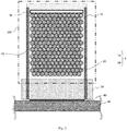
- a transport device includes, as illustrated in Fig. 1 , a support 5 configured to allow a plurality of articles 20 to be arranged on top; a discharging device 30 configured to push the plurality of articles 20 arranged on the support 5; a conveyor belt 40 configured to transport the articles pushed out from the support 5; a slider configured to move the articles 20 to position the articles 20 arranged on the support 5 apart from the articles 20 arranged on the conveyor belt 40; and a lift 80 configured to move upward to a position higher than upper surfaces of the support 5 and the conveyor belt 40 when the articles 20 arranged on the support 5 and the articles 20 arranged on the conveyor belt 40 are positioned apart from each other.
- the support 5 includes, as illustrated in Fig. 2 , a plate 10 disposed in a closed space 100, and a bridge 50 of which at least a part is disposed out of the closed space 100.
- the bridge 50 is disposed between the plate 10 and the conveyor belt 40.
- the closed space 100 may be provided, for example, by an oven, a tank, a storage room, and the like. In the closed space 100, at least one of a temperature and a pressure may be controlled. In the closed space 100, at least one of temperature distribution and pressure distribution may be controlled.
- the oven may be a freeze dry oven. The closed space 100 may be released by a door or the like. In the following description, an example in which the oven is a freeze dry oven will be described.
- Each of the plurality of articles 20 is, but not specifically limited to, a container, such as a vial, that stores pharmaceutical products to be subject, for example, to treatment such as freeze drying.
- a container such as a vial
- Each of the plurality of articles 20 includes, for example, a cylindrical shape.
- the plurality of articles 20 may be arranged in a staggered manner (staggered arrangement) such that a larger number of articles 20 can be arranged on the plate 10.
- the plurality of articles 20 are arranged in an overlapped manner when viewed from a side of a direction of travel of the discharging device 30.
- the plurality of articles 20 are arranged such that centers are alternating with each other by row extending substantially parallel to the conveyor belt 40 when viewed from above.
- the respective centers of the articles 20 in a second row are shifted with respect to the respective centers of the articles 20 in a first row on a conveyor belt 40 side in a direction of the row.
- the respective centers of the articles 20 in a third row are not generally shifted with respect to the respective centers of the articles 20 in the first row in the direction of the row.
- the centers of the plurality of articles 20 may be recognized as being arranged at intersections of a triangle grid pattern.
- a triangle forming the triangle grid pattern may be, and may not be a regular triangle.
- the articles 20, which are vials containing a drug therein, are carried into the freeze dry oven on the plate 10 in a state of being halfway closed.
- the cap is made, for example, of an elastic material such as rubber.
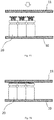
- an upper plate 11 disposed above the plate 10 in the freeze dry oven moves downward and presses the caps, which halfway close the vials, to completely close the vials, as illustrated in Fig. 3 .
- the vials may be closed completely by moving the plate 10 upward toward the upper plate 11 to bring the upper parts of the caps into contact with the upper plate 11.
- the upper plate 11 is moved upward so that the vials can be discharged from the freeze dry oven.
- the plate 10 may be moved downward so that the vials can be discharged from the freeze dry oven.
- the caps of some vials stick fast to the upper plate 11, and the some of the vials may be pulled up by the upper plate 11.
- the vial surrounded by other vials tends to drop to its original position without being fallen over, or to be held by the surrounding vials standing upright in a state of being suspended without being fallen over even when pulled up by the upper plate 11.
- the vial that is not surrounded by other vials like the vial in the first row on the conveyor belt 40 side, tends to drop and fall down when pulled up by the upper plate 11.
- the discharging device 30 pushes out the plurality of articles 20 on the plate 10 toward the conveyor belt 40 via the bridge 50.
- the discharging device 30 has, for example, a shape capable of coming into contact with an innermost row of the plurality of articles 20 in the closed space 100.
- the discharging device 30 has a shape capable of coming into contact with the row of the articles 20 on a side opposite from the conveyor belt 40 among the plurality of articles 20 on the plate 10.
- the shape of the discharging device 30 is, for example, a bar.
- a direction of pushing the articles 20 by the discharging device 30 is, for example, parallel to upper surfaces of the plate 10 and the bridge 50, and perpendicular to a direction of transport of the conveyor belt 40.
- a guide 70 may be provided in a vicinity of the plate 10 and the bridge 50 to prevent the articles 20 pushed by the discharging device 30 from spreading laterally with respect to the direction of travel of the discharging device 30.
- the conveyor belt 40 While the discharging device 30 pushes the articles 20 toward the conveyor belt 40, the conveyor belt 40 is positioned in a proximity of the bridge 50. During this period, a space may be present between the conveyor belt 40 and the bridge 50 to an extent that does not allow the articles 20 to drop. A height of the conveyor belt 40 and a height of the bridge 50 are adjusted so that the articles 20 do not fall down. As illustrated in Fig. 7 , the lift 80 may be stored between the bridge 50 and the conveyor belt 40 at a position lower than positions of upper surfaces of the bridge 50 and the conveyor belt 40 while the articles 20 are pushed from the bridge 50 to the conveyor belt 40.
- the shape of the lift 80 is, for example, a plate shape.
- the discharging device 30 illustrated in Fig. 6 stops.
- the predetermined number of rows may be a plurality of, that is two or more, rows.
- the discharging device 30 stops, for example, at least part of bottom surfaces of the un fallen articles 20 in a row closest to the bridge 50 on the conveyor belt 40 are situated on the lift 80, as illustrated in Fig. 8 .
- the bottom surfaces of the un fallen articles 20 of a row closest to the conveyor belt 40 on the bridge 50 are not situated on the lift 80.
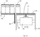
- a housing 61 is disposed below the conveyor belt 40.
- a slider 63 is disposed in the housing 61 to move, after the predetermined row of the articles 20 have pushed out from the bridge 50 onto the conveyor belt 40, the conveyor belt 40 in the discharging direction of the discharging device 30 and position the conveyor belt 40 apart from the bridge 50.
- a rail 62 is disposed in an interior of the housing 61. The slider 63 is movable along the rail 62.
- the slider 63 includes a contact part 64 capable of coming into contact with an underside surface structure 41 of the conveyor belt 40.
- the underside surface structure 41 of the conveyor belt 40 may be a protrusion or a recess.
- An opening for exposing the underside surface structure 41 of the conveyor belt 40 is provided on an upper surface of the housing 61.
- the upper surface of the housing 61 may be eliminated.
- the rail 62 is disposed in parallel to an underside surface of the conveyor belt 40 and perpendicular to the direction of transport of the conveyor belt 40. Therefore, the rail 62 is disposed parallel to the discharging direction of the discharging device 30 illustrated in Fig. 6 .
- the contact part 64 of the slider 63 illustrated in Fig. 7 may be a guide, such as a protrusion, provided on the slider 63 or may be a side surface of the slider 63.
- the slider 63 is, for example, self-propelled along the rail 62.
- the contact part 64 of the slider 63 comes into contact with a side surface of the underside surface structure 41 of the conveyor belt 40, and pushes the side surface of the underside surface structure 41. Accordingly, the conveyor belt 40 is pushed in the direction away from the bridge 50 and the conveyor belt 40 is positioned apart from the bridge 50. Therefore, as illustrated in Fig.
- the row of the articles 20 on the conveyor belt 40 is moved in a direction identical to the discharging direction of the discharging device 30 and are positioned apart from the row of the articles 20 on the bridge 50.
- the slider 63 positions the row of the articles 20 on the conveyor belt 40 apart from the row of the articles 20 on the bridge 50 so that a space for allowing the lift 80 moving upward to enter is formed between the un fallen articles 20 on the conveyor belt 40 and the un fallen articles 20 on the bridge 50.
- the conveyor belt 40 pushed by the slider 63 may be elastically deformed within a plane.
- the conveyor belt 40 includes a chain, a mesh, a slat, or the like, the conveyor belt 40 may be deformed within a plane by a decrease or an increase of distances among these components of the conveyor belt 40 pushed by the slider 63.
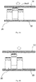
- the lift 80 is moved upward to a position higher than the upper surfaces of the bridge 50 and the conveyor belt 40.
- the lift 80 is moved upward to, for example, a height equal to or more than half the height of the articles 20 standing upright from the upper surfaces of the conveyor belt 40 and the bridge 50.
- Fallen articles 20Z situated between the bridge 50 and the conveyor belt 40 are restored to an upright position by the lift 80 moving upward.
- the center of gravity of the fallen articles 20Z is on a bridge 50 side, the articles 20Z are restored to the upright position by the lift 80 and stand on the bridge 50, as illustrated in Fig. 12 .
- the slider 63 moves toward the bridge 50 along the rail 62, and the conveyor belt 40 moves to a position proximal to the bridge 50 again, as illustrated in Fig. 13 and Fig. 14 .
- the articles 20 protruding from the conveyor belt 40 may come into contact with the side surface of the lift 80 and be pushed inward to the conveyor belt 40.
- the conveyor belt 40 is driven, and the row of the articles 20 on the conveyor belt 40 is transported by the conveyor belt 40.
- the lift 80 functions as a guide for impeding the articles 20 on the conveyor belt 40 from moving onto the bridge 50 and impeding the articles 20 on the bridge 50 from moving onto the conveyor belt 40.
- the transport device may further include a separation guide 91 configured to guide a direction of travel of the un fallen articles 20A transported by the conveyor belt 40 to a direction different from the direction of travel of the fallen articles 20Z.
- the separation guide 91 is provided at a position coming into contact with the un fallen articles 20A, but not coming into contact with the fallen articles 20Z. Therefore, the direction of travel of the un fallen articles 20A is guided by the separation guide 91.
- the un fallen articles 20A guided by the separation guide 91 are transferred to another conveyor belt 45 disposed, for example, at a position adjacent to the conveyor belt 40.
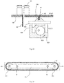
- the fallen articles 20Z are not guided in the direction of travel by the separation guide 91 and pass through the space below the separation guide 91. Ahead in the direction of travel of the conveyor 40 passing through the space below the separation guide 91, for example, a recycle bin 92 is disposed. The fallen articles 20Z drop into a recycling bin 92 from the conveyor belt 40.
- the lift 80 moves the fallen articles 20 across the bridge 50 and the conveyor belt 40 onto the bridge 50 or onto the conveyor belt 40, as illustrated in Fig. 11 and Fig. 16 . Therefore, the articles 20Z that are fallen so as to lie across the row of the articles 20 on the bridge 50 and the row of the articles on the conveyor belt 40 are eliminated, and thus the discharge of the articles 20 is not impeded.
- the transport device of the first embodiment even when the plurality of the articles 20 are arranged in a staggered manner on the plate 10 illustrated in Fig. 1 , the articles 20Z that are fallen so as to lie across the row of articles 20 on the bridge 50 and the row of articles on the conveyor belt 40 are eliminated, and the row of the articles 20 on the bridge 50 and the row of the articles on the conveyor belt 40 are separated by the lift 80, so that the row of the articles 20 transported by the conveyor belt 40 do not come into contact with the row of the articles 20 transported by the conveyor belt 40 a next time. Therefore, when sampling one or more of the articles 20 transported by the conveyor belt 40, where on the plate 10 the sampled article (s) 20 has (have) been positioned may easily be traced.
- a top view of a transport device according to a second embodiment is the same as the transport device according to the first embodiment illustrated in Fig. 1 .
- the transport device according to the second embodiment includes an eccentric cam 164 configured to move a passive slider 163, as illustrated in Fig. 22 and Fig. 23 .
- the eccentric cam 164 is rotated by a rotating device 165 such as a motor.
- a plane of rotation of the eccentric cam 164 is parallel to a direction of travel of discharging device 30.
- a recess 166 is provided at a bottom portion of the slider 163, and the eccentric cam 164 rotates in the recess 166 of the slider 163.
- the eccentric cam 164 rotates in the opposite direction, the slider 163 moves toward the bridge 50 along a rail 62, and the conveyor belt 40 moves to a position proximal to the bridge 50 again.
- Other components of the transport device according to the second embodiment may be the same as those in the first embodiment.
- a top view of a transport device according to a third embodiment is the same as the transport device according to the first embodiment illustrated in Fig. 1 .
- the transport device according to the third embodiment further includes gears 264 configured to guide a position of a conveyor belt 40, as illustrated in Fig. 25 .
- Examples of the gears 264 include a drive sprocket and a driven sprocket.
- the gears 264 fit an underside surface structure of the conveyor belt 40.
- the underside surface structure of the conveyor belt 40 may have a structure engaging the gears 264.
- the gears 264 are retained by shafts 265 disposed in a housing 61.
- the shafts 265 are disposed in parallel to an underside surface of the conveyor belt 40 and perpendicular to a direction of transport of the conveyor belt 40. Therefore, the shafts 265 are disposed parallel to a direction of travel of a discharging device 30.
- sliders 263 have a structure interposing the gears 264. Therefore, as illustrated in Fig. 27 , when the sliders 163 move in a direction away from the bridge 50 along the rail 62, the sliders 163 come into contact with side surfaces of the gears 264 and push the gears 264. Accordingly, the gears 264 are pushed in the direction away from the bridge 50. Furthermore, the conveyor belt 40 guided by the gears 264 is pushed in the direction away from the bridge 50 and the conveyor belt 40 is positioned apart from the bridge 50.
- articles to be transported in or out of an oven are not limited to those including pharmaceutical products, but may be articles such as food products, beverages, and precision parts, and may include any articles.
- the oven is not limited to a freeze dry oven, and may be a fermentation oven, or any oven which requires restraint of unevenness in temperature distribution or restraint of generation of dust in the interior. Any device may be used as the slider as long as it can position the articles arranged on the conveyor belt apart from the articles arranged on a support . In this manner, it should be understood that the present invention includes various embodiments which are not described in this specification.
Landscapes
- Engineering & Computer Science (AREA)
- Mechanical Engineering (AREA)
- Intermediate Stations On Conveyors (AREA)
Abstract
Description
- The present invention relates to a transport device.
- For example, when manufacturing products such as pharmaceutical products and food products, containers may be stored in an oven to apply temperature treatment or pressure treatment, such as freeze-drying treatment, to contents in the containers. A conveyor is disposed in front of the oven. The conveyor transports containers to be carried into the oven and containers discharged from the oven (for example, see Patent Literatures 1 to 3).
- Patent Literature 1 proposes a method of transferring a row of containers onto a conveyor by inserting a thin sheet from a conveyor side under a row of containers closest to the conveyor among a plurality of the containers arranged on a plate and pulling the sheet.
- Patent Literature 2 proposes a method of securing a row of containers adjacent to the row of containers pushed out onto the conveyor on the plate by a suction device to prevent the containers in the adjacent row of containers from being pulled out and mixed into the row of containers pushed out onto the conveyor when the containers are discharged by pushing out from an oven via the plate onto a conveyor.
- Patent Literature 3 proposes a method of pushing a row of containers from a plurality of the containers arranged on a plate onto a conveyor, and then moving the plate with the containers arranged thereon upward or moving the conveyor downward to prevent the containers on the plate from coming into contact with the conveyor.
-
- PTL 1:
EP1717533B - PTL 2:
WO2015/082563A - PTL 3:
US2009/208320A - If some of containers pushed out of an oven onto a conveyor fall over, such fallen container(s) may impede discharging of other containers when the conveyor is activated. In addition, not only for steps of manufacturing pharmaceutical products or food products, a technology which enables transport of a plurality of articles to the conveyor while avoiding an influence of the fallen articles is required. Accordingly, it is one of objects of the present invention to provide a transport device capable of transporting the plurality of articles onto the conveyor while avoiding an influence of the fallen articles .
- According to an aspect of the present invention, there is provided a transport device including: a support configured to allow a plurality of articles to be arranged on top; a discharging device configured to push the plurality of articles arranged on the support; a conveyor belt configured to transport the articles pushed out from the support; and a slider configured to move the articles to position the articles arranged on the support apart from the articles arranged on the conveyor belt; and a lift disposed between the support and the conveyor belt and configured to move upward to a position higher than upper surfaces of the support and the conveyor belt when the articles arranged on the support and the articles arranged on the conveyor belt are positioned apart from each other.
- In the transport device described above, the lift may be stored at a position lower than positions of the upper surfaces of the support and the conveyor belt while the plurality of articles are pushed out onto the conveyor belt from the support.
- In the transport device described above, the discharging device may push the plurality of articles until at least part of articles which are to be moved by the slider and have not fallen over are positioned on the stored lift.
- In the transport device described above, the slider may position the articles arranged on the support and the articles arranged on the conveyor belt apart from each other to form a space to allow the lift moving upward to enter between the unfallen articles on the support and the unfallen articles on the conveyor belt.
- In the transport device described above, the slider may move the articles arranged on the conveyor belt in a direction identical to a discharging direction of the discharging device so that the articles arranged on the conveyor belt are positioned apart from the articles arranged on the support.
- In the transport device described above, the slider may move the conveyor belt in a direction identical to the direction in which the discharging device discharges the articles and position the conveyor belt apart from the support.
- In the transport device described above, the slider may have a contact part that comes into contact with an underside surface structure of the conveyor belt, and the conveyor belt may be positioned apart from the support by the contact part of the slider pushing the underside surface structure of the conveyor belt.
- In the transport device described above, the underside surface structure of the conveyor belt is a protrusion, and the conveyor belt may be positioned apart from the support by pushing the protrusion on an underside surface of the conveyor belt by the contact part of the slider.
- The transport device described above may further include an eccentric cam for moving the slider.
- The transport device described above may further include a gear configured to guide the position of the conveyor belt and the conveyor belt may be moved by moving the gear by the slider.
- In the transport device described above, the conveyor belt may be made of an elastic material. The conveyor belt may include a chain.
- In the transport device described above, the lift moving upward may move articles fallen across the support and the conveyor belt onto the support or the conveyor belt.
- In the transport device described above, the shape of the lift may be a plate shape.
- The transport device described above may further include a separation guide configured to separate the unfallen articles from the fallen articles on the conveyor belt.
- According to an aspect of the present invention, there is provided an oven system including: an oven; a plate disposed in the oven; a discharging device configured to push a plurality of the articles arranged on the plate; a bridge disposed adjacent to the plate; a conveyor belt disposed adjacent to the bridge and disposed outside of the oven for transporting the articles pushed out from the plate; a slider configured to move the articles to position the articles arranged on the bridge apart from the articles arranged on the conveyor belt; and a lift disposed between the bridge and the conveyor belt and configured to move upward to a position higher than upper surfaces of the bridge and the conveyor belt when the articles arranged on the bridge and the articles arranged on the conveyor belt are positioned apart from each other.
- In the oven system described above, the lift may be stored at a position lower than the upper surfaces of the bridge and the conveyor belt while the plurality of articles are pushed out onto the conveyor belt from the bridge.
- In the oven system described above, the discharging device may push the plurality of articles until at least part of articles which are to be moved by the slider and have kept unfallen are positioned on the stored lift.
- In the oven system described above, the slider may position the articles arranged on the bridge apart from the articles arranged on the conveyor belt to form a space to allow the lift moving upward to enter between the unfallen articles on the bridge and the unfallen articles on the conveyor belt.
- In the oven system described above, the slider may move the articles arranged on the conveyor belt in a direction identical to the discharging direction of the discharging device so that the articles arranged on the conveyor belt are positioned apart from the articles arranged on the bridge.
- In the oven system described above, the slider may move the conveyor belt in a direction identical to the direction in which the discharging device pushes the articles and positions the conveyor belt apart from the bridge.
- In the oven system described above, the slider may have the contact part that comes into contact with an underside surface structure of the conveyor belt, and the conveyor belt may be positioned apart from the bridge by the contact part of the slider pushing the underside surface structure of the conveyor belt.
- In the oven system described above, the underside surface structure of the conveyor belt is a protrusion, and the conveyor belt may be separated from the bridge by pushing the protrusion on the underside surface of the conveyor belt by the contact part of the slider.
- The oven system described above may further include an eccentric cam for moving the slider.
- The oven system described above may further include a gear configured to guide a position of the conveyor belt and the conveyor belt may be moved by moving the gear by the slider.
- In the oven system described above, the conveyor belt may be an elastic body. The conveyor belt may include a chain.
- In the oven system described above, the lift moving upward may move the articles fallen across the bridge and the conveyor belt onto the bridge or the conveyor belt.
- In the oven system described above, the shape of the lift may be a plate shape.
- The oven system described above may further include a separation guide configured to separate the unfallen articles from the fallen articles on the conveyor belt.
- In the oven system described above, the articles may be vials and the oven system may further include an upper plate disposed above the plate in the oven and configured to come into contact with upper parts of caps of the vials halfway closed by caps to completely close the vials.
- In the oven system described above, the oven may be a freeze dry oven.
- The present invention can provide a transport device capable of transporting a plurality of articles onto a conveyor while avoiding an influence of fallen articles.
-
- [
Fig. 1] Fig. 1 is a schematic top view of a transport device according to a first embodiment. - [
Fig. 2] Fig. 2 is a schematic top view of the transport device according to the first embodiment. - [
Fig. 3] Fig. 3 is a schematic side view of the transport device according to the first embodiment. - [
Fig. 4] Fig. 4 is a schematic side view of the transport device according to the first embodiment. - [
Fig. 5] Fig. 5 is a schematic side view of the transport device according to the first embodiment. - [
Fig. 6] Fig. 6 is a schematic top view of the transport device according to the first embodiment. - [
Fig. 7] Fig. 7 is a schematic side view of the transport device according to the first embodiment. - [
Fig. 8] Fig. 8 is a schematic side view of the transport device according to the first embodiment. - [
Fig. 9] Fig. 9 is a schematic side view of the transport device according to the first embodiment. - [
Fig. 10] Fig. 10 is a schematic side view of the transport device according to the first embodiment. - [
Fig. 11] Fig. 11 is a schematic side view of the transport device according to the first embodiment. - [
Fig. 12] Fig. 12 is a schematic top view of the transport device according to the first embodiment. - [
Fig. 13] Fig. 13 is a schematic top view of the transport device according to the first embodiment. - [
Fig. 14] Fig. 14 is a schematic side view of the transport device according to the first embodiment. - [
Fig. 15] Fig. 15 is a schematic top view of the transport device according to the first embodiment. - [
Fig. 16] Fig. 16 is a schematic side view of the transport device according to the first embodiment. - [
Fig. 17] Fig. 17 is a schematic top view of the transport device according to the first embodiment. - [
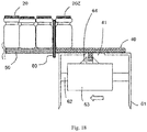
Fig. 18] Fig. 18 is a schematic side view of the transport device according to the first embodiment. - [
Fig. 19] Fig. 19 is a schematic top view of the transport device according to the first embodiment. - [
Fig. 20] Fig. 20 illustrates a schematic top view (a) and a schematic front view (b) of the transport device according to the first embodiment. - [
Fig. 21] Fig. 21 is a schematic top view of a transport device according to a reference example. - [
Fig. 22] Fig. 22 is a schematic top view of a transport device according to a second embodiment. - [
Fig. 23] Fig. 23 is a schematic side view of the transport device according to the second embodiment. - [
Fig. 24] Fig. 24 is a schematic side view of the transport device according to the second embodiment. - [
Fig. 25] Fig. 25 is a schematic front view of a transport device according to a third embodiment. - [
Fig. 26] Fig. 26 is a schematic side view of the transport device according to the third embodiment. - [
Fig. 27] Fig. 27 is a schematic side view of the transport device according to the third embodiment. - An embodiment of the present invention will be described below. In the drawings, the same or similar parts are designated by the same or similar reference signs. However, the drawings are schematic illustrations. Therefore, specific dimensions or the like are to be determined based on the following description. In addition, the drawings may include parts having different dimensional relationships and ratios from each other as a matter of course.
- A transport device according to a first embodiment includes, as illustrated in
Fig. 1 , asupport 5 configured to allow a plurality ofarticles 20 to be arranged on top; a dischargingdevice 30 configured to push the plurality ofarticles 20 arranged on thesupport 5; aconveyor belt 40 configured to transport the articles pushed out from thesupport 5; a slider configured to move thearticles 20 to position thearticles 20 arranged on thesupport 5 apart from thearticles 20 arranged on theconveyor belt 40; and alift 80 configured to move upward to a position higher than upper surfaces of thesupport 5 and theconveyor belt 40 when thearticles 20 arranged on thesupport 5 and thearticles 20 arranged on theconveyor belt 40 are positioned apart from each other. - The
support 5 includes, as illustrated inFig. 2 , aplate 10 disposed in aclosed space 100, and abridge 50 of which at least a part is disposed out of theclosed space 100. Thebridge 50 is disposed between theplate 10 and theconveyor belt 40. Theclosed space 100 may be provided, for example, by an oven, a tank, a storage room, and the like. In theclosed space 100, at least one of a temperature and a pressure may be controlled. In theclosed space 100, at least one of temperature distribution and pressure distribution may be controlled. The oven may be a freeze dry oven. Theclosed space 100 may be released by a door or the like. In the following description, an example in which the oven is a freeze dry oven will be described. - Each of the plurality of
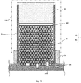
articles 20 is, but not specifically limited to, a container, such as a vial, that stores pharmaceutical products to be subject, for example, to treatment such as freeze drying. In the following description, an example in which thearticles 20 are vials will be described. Each of the plurality ofarticles 20 includes, for example, a cylindrical shape. The plurality ofarticles 20 may be arranged in a staggered manner (staggered arrangement) such that a larger number ofarticles 20 can be arranged on theplate 10. In this case, the plurality ofarticles 20 are arranged in an overlapped manner when viewed from a side of a direction of travel of the dischargingdevice 30. The plurality ofarticles 20 are arranged such that centers are alternating with each other by row extending substantially parallel to theconveyor belt 40 when viewed from above. - For example, the respective centers of the
articles 20 in a second row are shifted with respect to the respective centers of thearticles 20 in a first row on aconveyor belt 40 side in a direction of the row. However, the respective centers of thearticles 20 in a third row are not generally shifted with respect to the respective centers of thearticles 20 in the first row in the direction of the row. The centers of the plurality ofarticles 20 may be recognized as being arranged at intersections of a triangle grid pattern. However, in this disclosure, a triangle forming the triangle grid pattern may be, and may not be a regular triangle. - The
articles 20, which are vials containing a drug therein, are carried into the freeze dry oven on theplate 10 in a state of being halfway closed. The cap is made, for example, of an elastic material such as rubber. When a drug in an interior is freeze dried, anupper plate 11 disposed above theplate 10 in the freeze dry oven moves downward and presses the caps, which halfway close the vials, to completely close the vials, as illustrated inFig. 3 . Alternatively, the vials may be closed completely by moving theplate 10 upward toward theupper plate 11 to bring the upper parts of the caps into contact with theupper plate 11. Then, as illustrated inFig. 4 , theupper plate 11 is moved upward so that the vials can be discharged from the freeze dry oven. Alternatively, theplate 10 may be moved downward so that the vials can be discharged from the freeze dry oven. - When the
plate 10 and theupper plate 11 move relatively away from each other, the caps of some vials stick fast to theupper plate 11, and the some of the vials may be pulled up by theupper plate 11. In this situation, the vial surrounded by other vials tends to drop to its original position without being fallen over, or to be held by the surrounding vials standing upright in a state of being suspended without being fallen over even when pulled up by theupper plate 11. In contrast, as illustrated inFig. 5 , the vial that is not surrounded by other vials, like the vial in the first row on theconveyor belt 40 side, tends to drop and fall down when pulled up by theupper plate 11. - When taking the plurality of
articles 20 from theclosed space 100 after the caps are completely closed, a door of the oven, or the like, that provides theclosed space 100 is opened, as illustrated inFig. 6 . In addition, the dischargingdevice 30 pushes out the plurality ofarticles 20 on theplate 10 toward theconveyor belt 40 via thebridge 50. The dischargingdevice 30 has, for example, a shape capable of coming into contact with an innermost row of the plurality ofarticles 20 in theclosed space 100. In other words, the dischargingdevice 30 has a shape capable of coming into contact with the row of thearticles 20 on a side opposite from theconveyor belt 40 among the plurality ofarticles 20 on theplate 10. The shape of the dischargingdevice 30 is, for example, a bar. A direction of pushing thearticles 20 by the dischargingdevice 30 is, for example, parallel to upper surfaces of theplate 10 and thebridge 50, and perpendicular to a direction of transport of theconveyor belt 40. Aguide 70 may be provided in a vicinity of theplate 10 and thebridge 50 to prevent thearticles 20 pushed by the dischargingdevice 30 from spreading laterally with respect to the direction of travel of the dischargingdevice 30. - While the discharging
device 30 pushes thearticles 20 toward theconveyor belt 40, theconveyor belt 40 is positioned in a proximity of thebridge 50. During this period, a space may be present between theconveyor belt 40 and thebridge 50 to an extent that does not allow thearticles 20 to drop. A height of theconveyor belt 40 and a height of thebridge 50 are adjusted so that thearticles 20 do not fall down. As illustrated inFig. 7 , thelift 80 may be stored between thebridge 50 and theconveyor belt 40 at a position lower than positions of upper surfaces of thebridge 50 and theconveyor belt 40 while thearticles 20 are pushed from thebridge 50 to theconveyor belt 40. The shape of thelift 80 is, for example, a plate shape. After a predetermined number of rows, for example, a row of thearticles 20, is pushed onto theconveyor belt 40, the dischargingdevice 30 illustrated inFig. 6 stops. Note that the predetermined number of rows may be a plurality of, that is two or more, rows. - When the discharging
device 30 stops, for example, at least part of bottom surfaces of theunfallen articles 20 in a row closest to thebridge 50 on theconveyor belt 40 are situated on thelift 80, as illustrated inFig. 8 . In contrast, the bottom surfaces of theunfallen articles 20 of a row closest to theconveyor belt 40 on thebridge 50 are not situated on thelift 80. - As illustrated in
Fig. 7 , ahousing 61 is disposed below theconveyor belt 40. Aslider 63 is disposed in thehousing 61 to move, after the predetermined row of thearticles 20 have pushed out from thebridge 50 onto theconveyor belt 40, theconveyor belt 40 in the discharging direction of the dischargingdevice 30 and position theconveyor belt 40 apart from thebridge 50. Arail 62 is disposed in an interior of thehousing 61. Theslider 63 is movable along therail 62. Theslider 63 includes acontact part 64 capable of coming into contact with anunderside surface structure 41 of theconveyor belt 40. - The
underside surface structure 41 of theconveyor belt 40 may be a protrusion or a recess. An opening for exposing theunderside surface structure 41 of theconveyor belt 40 is provided on an upper surface of thehousing 61. Alternatively, the upper surface of thehousing 61 may be eliminated. Therail 62 is disposed in parallel to an underside surface of theconveyor belt 40 and perpendicular to the direction of transport of theconveyor belt 40. Therefore, therail 62 is disposed parallel to the discharging direction of the dischargingdevice 30 illustrated inFig. 6 . - The
contact part 64 of theslider 63 illustrated inFig. 7 may be a guide, such as a protrusion, provided on theslider 63 or may be a side surface of theslider 63. Theslider 63 is, for example, self-propelled along therail 62. As illustrated inFig. 9 , when theslider 63 moves in a direction away from thebridge 50 along therail 62, thecontact part 64 of theslider 63 comes into contact with a side surface of theunderside surface structure 41 of theconveyor belt 40, and pushes the side surface of theunderside surface structure 41. Accordingly, theconveyor belt 40 is pushed in the direction away from thebridge 50 and theconveyor belt 40 is positioned apart from thebridge 50. Therefore, as illustrated inFig. 1 , the row of thearticles 20 on theconveyor belt 40 is moved in a direction identical to the discharging direction of the dischargingdevice 30 and are positioned apart from the row of thearticles 20 on thebridge 50. As illustrated inFig. 10 , theslider 63 positions the row of thearticles 20 on theconveyor belt 40 apart from the row of thearticles 20 on thebridge 50 so that a space for allowing thelift 80 moving upward to enter is formed between theunfallen articles 20 on theconveyor belt 40 and theunfallen articles 20 on thebridge 50. - When the
conveyor belt 40 is made of an elastic material, theconveyor belt 40 pushed by theslider 63 may be elastically deformed within a plane. When theconveyor belt 40 includes a chain, a mesh, a slat, or the like, theconveyor belt 40 may be deformed within a plane by a decrease or an increase of distances among these components of theconveyor belt 40 pushed by theslider 63. - As illustrated in
Fig. 11 , when the row of thearticles 20 on theconveyor belt 40 is positioned apart from thebridge 50 by theslider 63, thelift 80 is moved upward to a position higher than the upper surfaces of thebridge 50 and theconveyor belt 40. Thelift 80 is moved upward to, for example, a height equal to or more than half the height of thearticles 20 standing upright from the upper surfaces of theconveyor belt 40 and thebridge 50. Fallen articles 20Z situated between thebridge 50 and theconveyor belt 40 are restored to an upright position by thelift 80 moving upward. When the center of gravity of the fallen articles 20Z is on abridge 50 side, the articles 20Z are restored to the upright position by thelift 80 and stand on thebridge 50, as illustrated inFig. 12 . - Subsequently, the
slider 63 moves toward thebridge 50 along therail 62, and theconveyor belt 40 moves to a position proximal to thebridge 50 again, as illustrated inFig. 13 andFig. 14 . Thearticles 20 protruding from theconveyor belt 40 may come into contact with the side surface of thelift 80 and be pushed inward to theconveyor belt 40. Subsequently, as illustrated inFig. 15 , theconveyor belt 40 is driven, and the row of thearticles 20 on theconveyor belt 40 is transported by theconveyor belt 40. During this period, thelift 80 functions as a guide for impeding thearticles 20 on theconveyor belt 40 from moving onto thebridge 50 and impeding thearticles 20 on thebridge 50 from moving onto theconveyor belt 40. - Note that when the centers of gravity of the fallen articles 20Z which reside between the
bridge 50 and theconveyor belt 40 illustrated inFig. 9 are on theconveyor belt 40 side, the articles 20Z are restored to the upright position by thelift 80 and stand on theconveyor belt 40, as illustrated inFig. 16 . Next, as illustrated inFig. 17 andFig. 18 , theconveyor belt 40 moves to the position proximal to thebridge 50 again. The articles 20Z leaning against thelift 80 on theconveyor belt 40 may stand upright by the movement of theconveyor belt 40 to the position proximal to thelift 80. Subsequently, as illustrated inFig. 19 , theconveyor belt 40 is driven, and the row of thearticles 20 on theconveyor belt 40 is transported by theconveyor belt 40. Subsequently, thelift 80 moves downward, and discharge of thearticles 20 for each predetermined row is repeated in the same procedure as for the first row. - As illustrated in
Fig. 20(a) , which is a top view andFig. 20(b) , which is a front view, the transport device according to the first embodiment may further include aseparation guide 91 configured to guide a direction of travel of theunfallen articles 20A transported by theconveyor belt 40 to a direction different from the direction of travel of the fallen articles 20Z. For example, theseparation guide 91 is provided at a position coming into contact with theunfallen articles 20A, but not coming into contact with the fallen articles 20Z. Therefore, the direction of travel of theunfallen articles 20A is guided by theseparation guide 91. Theunfallen articles 20A guided by theseparation guide 91 are transferred to anotherconveyor belt 45 disposed, for example, at a position adjacent to theconveyor belt 40. In contrast, the fallen articles 20Z are not guided in the direction of travel by theseparation guide 91 and pass through the space below theseparation guide 91. Ahead in the direction of travel of theconveyor 40 passing through the space below theseparation guide 91, for example, arecycle bin 92 is disposed. The fallen articles 20Z drop into arecycling bin 92 from theconveyor belt 40. - As illustrated in
Fig. 21 , if aconveyor belt 340 is driven with the fallen articles 20Z remaining between theconveyor belt 340 and thebridge 50, the fallen articles 20Z are caught between thearticles 20 on thebridge 50 and thearticles 20 on theconveyor belt 340, which may result in an impediment to the discharge of thearticles 20. - In contrast, according to the transport device of the first embodiment, the
lift 80 moves the fallenarticles 20 across thebridge 50 and theconveyor belt 40 onto thebridge 50 or onto theconveyor belt 40, as illustrated inFig. 11 andFig. 16 . Therefore, the articles 20Z that are fallen so as to lie across the row of thearticles 20 on thebridge 50 and the row of the articles on theconveyor belt 40 are eliminated, and thus the discharge of thearticles 20 is not impeded. - In addition, according to the transport device of the first embodiment, even when the plurality of the
articles 20 are arranged in a staggered manner on theplate 10 illustrated inFig. 1 , the articles 20Z that are fallen so as to lie across the row ofarticles 20 on thebridge 50 and the row of articles on theconveyor belt 40 are eliminated, and the row of thearticles 20 on thebridge 50 and the row of the articles on theconveyor belt 40 are separated by thelift 80, so that the row of thearticles 20 transported by theconveyor belt 40 do not come into contact with the row of thearticles 20 transported by the conveyor belt 40 a next time. Therefore, when sampling one or more of thearticles 20 transported by theconveyor belt 40, where on theplate 10 the sampled article (s) 20 has (have) been positioned may easily be traced. - A top view of a transport device according to a second embodiment is the same as the transport device according to the first embodiment illustrated in
Fig. 1 . The transport device according to the second embodiment includes aneccentric cam 164 configured to move apassive slider 163, as illustrated inFig. 22 and Fig. 23 . Theeccentric cam 164 is rotated by arotating device 165 such as a motor. A plane of rotation of theeccentric cam 164 is parallel to a direction of travel of dischargingdevice 30. Arecess 166 is provided at a bottom portion of theslider 163, and theeccentric cam 164 rotates in therecess 166 of theslider 163. - As illustrated in
Fig. 24 , when theeccentric cam 164 rotates in a certain direction, theeccentric cam 164 comes into contact with a part of an inner wall of therecess 166 on a far side frombridge 50 and pushes the inner wall. Accordingly, theslider 163 is pushed in a direction away from thebridge 50. Acontact part 64 of theslider 163 comes into contact with a side surface of anunderside surface structure 41 ofconveyor belt 40 and pushes the side surface of theunderside surface structure 41. Therefore, theconveyor belt 40 is pushed in a direction away from thebridge 50 and theconveyor belt 40 is positioned apart from thebridge 50. - After the
lift 80 is moved upward, theeccentric cam 164 rotates in the opposite direction, theslider 163 moves toward thebridge 50 along arail 62, and theconveyor belt 40 moves to a position proximal to thebridge 50 again. Other components of the transport device according to the second embodiment may be the same as those in the first embodiment. - A top view of a transport device according to a third embodiment is the same as the transport device according to the first embodiment illustrated in
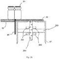
Fig. 1 . The transport device according to the third embodiment further includesgears 264 configured to guide a position of aconveyor belt 40, as illustrated inFig. 25 . Examples of thegears 264 include a drive sprocket and a driven sprocket. Thegears 264 fit an underside surface structure of theconveyor belt 40. The underside surface structure of theconveyor belt 40 may have a structure engaging thegears 264. As illustrated inFig. 26 , thegears 264 are retained byshafts 265 disposed in ahousing 61. Theshafts 265 are disposed in parallel to an underside surface of theconveyor belt 40 and perpendicular to a direction of transport of theconveyor belt 40. Therefore, theshafts 265 are disposed parallel to a direction of travel of a dischargingdevice 30. - In the third embodiment,
sliders 263 have a structure interposing thegears 264. Therefore, as illustrated inFig. 27 , when thesliders 163 move in a direction away from thebridge 50 along therail 62, thesliders 163 come into contact with side surfaces of thegears 264 and push thegears 264. Accordingly, thegears 264 are pushed in the direction away from thebridge 50. Furthermore, theconveyor belt 40 guided by thegears 264 is pushed in the direction away from thebridge 50 and theconveyor belt 40 is positioned apart from thebridge 50. - After a
lift 80 has moved upward, thesliders 263 move along therail 62 toward thebridge 50 and push thegears 264 toward thebridge 50. Accordingly, theconveyor belt 40 moves to the position proximal to thebridge 50 again. Other components of the transport device according to the third embodiment may be the same as those in the first embodiment. - Although the present invention has been described based on the embodiments, description and drawings which constitute part of this disclosure should not be interpreted to limit the present invention. From this disclosure, various alternative embodiments, examples, and operational technologies will become apparent for those skilled in the art. For example, articles to be transported in or out of an oven are not limited to those including pharmaceutical products, but may be articles such as food products, beverages, and precision parts, and may include any articles. The oven is not limited to a freeze dry oven, and may be a fermentation oven, or any oven which requires restraint of unevenness in temperature distribution or restraint of generation of dust in the interior. Any device may be used as the slider as long as it can position the articles arranged on the conveyor belt apart from the articles arranged on a support . In this manner, it should be understood that the present invention includes various embodiments which are not described in this specification.
- 5 ... support, 10 ... plate, 11 ... upper plate, 20 ... article, 30 ... discharging device, 40, 45 ... conveyor belt, 41 ... underside surface structure, 50 ... bridge, 61 ... housing, 62 ... rail, 63 ... slider, 64 ... contact part, 70 ... guide, 80 ... lift, 91 ... separation guide, 92 ... recycle bin, 100 ... closed space, 163 ... slider, 164 ... eccentric cam, 165 ... rotating device, 166 ... recess, 263 ... slider, 264 ... gear, 265 ... shaft, 340 ... conveyor belt
Claims (10)
- A transport device comprising:a support configured to allow a plurality of articles to be arranged on top;a discharging device configured to push the plurality of articles arranged on the support;a conveyor belt configured to transport the articles pushed out from the support;a slider configured to move the articles to position the articles arranged on the support apart from the articles arranged on the conveyor belt; anda lift disposed between the support and the conveyor belt and configured to move upward to a position higher than upper surfaces of the support and the conveyor belt when the articles arranged on the support and the articles arranged on the conveyor belt are positioned apart from each other.
- The transport device according to Claim 1, wherein the lift is stored at a position lower than the upper surfaces of the support and the conveyor belt while the plurality of articles are pushed out onto the conveyor belt from the support .
- The transport device according to Claim 1 or 2, wherein the slider positions the articles arranged on the support apart from the articles arranged on the conveyor belt to form a space to allow the lift moving upward to enter between unfallen articles on the support and the unfallen articles on the conveyor belt.
- The transport device according to any one of Claims 1 to 3, wherein the slider moves the conveyor belt in a direction identical to a direction in which the discharging device pushes the articles and positions the conveyor belt apart from the support.
- The transport device according to Claim 4, wherein the slider includes a contact part configured to come into contact with an underside surface structure of the conveyor belt, and
the conveyor belt is positioned apart from the support by pushing the underside surface structure of the conveyor belt by the contact part of the slider. - The transport device according to Claim 5, wherein the underside surface structure of the conveyor belt is a protrusion, and
the conveyor belt is positioned apart from the support by pushing the protrusion on an underside surface of the conveyor belt by the contact part of the slider. - The transport device according to any one of Claims 4 to 6, further comprising an eccentric cam configured to move the slider.
- The transport device according to any one of Claims 4 to 6, further comprising:a gear configured to guide the position of the conveyor belt,wherein the conveyor belt is moved by the slider moving the gear.
- The transport device according to Claim 1, wherein the lift moving upward moves articles fallen across a part between the support and the conveyor belt onto the support or the conveyor belt.
- The transport device according to Claim 1 further comprising a separation guide configured to separate the unfallen articles from the fallen articles on the conveyor belt .
Applications Claiming Priority (1)
| Application Number | Priority Date | Filing Date | Title |
|---|---|---|---|
| PCT/JP2018/015616 WO2019198243A1 (en) | 2018-04-13 | 2018-04-13 | Transport device |
Publications (2)
| Publication Number | Publication Date |
|---|---|
| EP3778443A1 true EP3778443A1 (en) | 2021-02-17 |
| EP3778443A4 EP3778443A4 (en) | 2021-12-01 |
Family
ID=68163538
Family Applications (1)
| Application Number | Title | Priority Date | Filing Date |
|---|---|---|---|
| EP18914867.9A Withdrawn EP3778443A4 (en) | 2018-04-13 | 2018-04-13 | TRANSPORTATION DEVICE |
Country Status (4)
| Country | Link |
|---|---|
| US (1) | US11097905B2 (en) |
| EP (1) | EP3778443A4 (en) |
| CN (1) | CN111936402A (en) |
| WO (1) | WO2019198243A1 (en) |
Family Cites Families (27)
| Publication number | Priority date | Publication date | Assignee | Title |
|---|---|---|---|---|
| US2992717A (en) * | 1958-09-16 | 1961-07-18 | Taylor Mfg Co Inc | Article receiving and storage apparatus |
| US3369642A (en) * | 1966-06-17 | 1968-02-20 | Richardson Merrell Inc | Apparatus for removing tipped-over bottles from a conveyor |
| US3610399A (en) * | 1969-09-10 | 1971-10-05 | Ato Inc | Article conveyor having ejecting means for tipped or fallen articles |
| US3987889A (en) * | 1972-12-18 | 1976-10-26 | Aurora Nieto Godoy | Distributor mechanism for articles coming off a conveyor |
| IE44296B1 (en) * | 1976-10-13 | 1981-10-07 | Powers Manufacturing | Method and apparatus for checkweighing glass containers |
| JPS6375199A (en) * | 1986-09-10 | 1988-04-05 | 新王子製紙株式会社 | release paper |
| JPH01180422U (en) | 1988-06-08 | 1989-12-26 | ||
| JP2523375B2 (en) * | 1989-06-15 | 1996-08-07 | 株式会社小松製作所 | Liquid crystal light control element |
| JP2837743B2 (en) | 1990-06-27 | 1998-12-16 | 富士通株式会社 | Charged particle beam exposure method and stencil mask used therefor |
| JPH04115817U (en) | 1991-03-25 | 1992-10-15 | 雪印ローリー株式会社 | Fallen container removal device for conveyor |
| JPH0784253B2 (en) | 1992-05-08 | 1995-09-13 | 株式会社矢口鉄工所 | Simple depalletizer |
| US6419442B1 (en) * | 1998-08-25 | 2002-07-16 | Dorner Mfg. Corp. | Mechanism and method for forming a stack of articles |
| JP4264168B2 (en) * | 1999-09-30 | 2009-05-13 | 澁谷工業株式会社 | Article branching device |
| DE102005019985B4 (en) * | 2005-04-27 | 2010-12-30 | Accurro Gmbh | A method for the controlled removal of a number of vials from a freeze dryer and apparatus therefor |
| US8770909B2 (en) * | 2007-01-31 | 2014-07-08 | Kaufmann Engineered Group | Layer formation table and process |
| DE102008009993B4 (en) | 2008-02-19 | 2016-01-28 | Hof Sonderanlagenbau Gmbh | A method for serially separating a number of vials from a plurality of multi-row vials and apparatus therefor |
| JP5359060B2 (en) * | 2008-06-27 | 2013-12-04 | 澁谷工業株式会社 | Container delivery device |
| JP5533615B2 (en) * | 2010-12-09 | 2014-06-25 | 株式会社ダイフク | Introduction and delivery device |
| DE102011050185A1 (en) * | 2011-05-06 | 2012-11-08 | Krones Aktiengesellschaft | Method and device for deflecting and aligning piece goods or articles |
| DE102012204013B4 (en) * | 2012-03-14 | 2025-10-02 | Krones Aktiengesellschaft | Method and device for transferring article layers between adjacent modules |
| JP6245793B2 (en) * | 2012-04-13 | 2017-12-13 | 日本山村硝子株式会社 | Cutting conveyor and cutting conveying method |
| CN202828974U (en) * | 2012-08-01 | 2013-03-27 | 杭州永创智能设备股份有限公司 | Low-position in-out bottle unscrambler |
| CN203580103U (en) * | 2013-11-18 | 2014-05-07 | 广东福朗德机械有限公司 | Bottle preform seating device of bottle blowing machine |
| DE102013225047A1 (en) * | 2013-12-05 | 2015-06-11 | Gea Lyophil Gmbh | Discharge device with vacuum suction |
| CN204872749U (en) * | 2015-08-04 | 2015-12-16 | 湖南科伦制药有限公司 | Bottle conveyor |
| CN107777309A (en) * | 2016-08-25 | 2018-03-09 | 史军 | A kind of transmitting device for tyre production streamline |
| CN106742289A (en) * | 2016-12-23 | 2017-05-31 | 云南白药集团股份有限公司 | A kind of 90 degree based on gravitational effect are turned over box device |
-
2018
- 2018-04-13 CN CN201880092224.6A patent/CN111936402A/en active Pending
- 2018-04-13 EP EP18914867.9A patent/EP3778443A4/en not_active Withdrawn
- 2018-04-13 WO PCT/JP2018/015616 patent/WO2019198243A1/en not_active Ceased
- 2018-04-13 US US17/046,555 patent/US11097905B2/en not_active Expired - Fee Related
Also Published As
| Publication number | Publication date |
|---|---|
| US20210147159A1 (en) | 2021-05-20 |
| EP3778443A4 (en) | 2021-12-01 |
| CN111936402A (en) | 2020-11-13 |
| WO2019198243A1 (en) | 2019-10-17 |
| US11097905B2 (en) | 2021-08-24 |
Similar Documents
| Publication | Publication Date | Title |
|---|---|---|
| DK2816305T3 (en) | Device for reading and reading a deposition plate of a freeze-drying plant and a method for this | |
| TWI623312B (en) | Drug feeder | |
| US4164997A (en) | Article transport device and method | |
| EP3484775B1 (en) | Method device for handling primary containers for pharmaceutical use | |
| US7866936B2 (en) | System and method for transferring mail between containers | |
| US10517798B2 (en) | Medicine feeding canister for in an automated medicine dispensing device | |
| US11213861B2 (en) | Conveyed article sorting device | |
| JP5837181B2 (en) | Container filling device | |
| KR20140107568A (en) | Method and apparatus for filling capsules with loose material and for their sealing | |
| KR100415736B1 (en) | Drug Dispenser and Drug Distribution Method | |
| US20130174514A1 (en) | Packaging system | |
| US11097905B2 (en) | Transport device | |
| US11053083B2 (en) | Transport device | |
| GB2104028A (en) | Packing biscuits, fish fingers or the like | |
| US20210163234A1 (en) | Transport device and furnace system | |
| US4567712A (en) | Vacuum transfer apparatus for packing layers of articles in a container | |
| JP7687691B2 (en) | Equipment for aligning and feeding flanged containers | |
| EP2172398B1 (en) | Device for stacking a plurality of disc-shaped products | |
| US11261034B2 (en) | Transport device and freeze-drying system | |
| CN220483705U (en) | Automatic medicine packaging device | |
| WO2019234644A1 (en) | Unloader of rod-like articles of the tobacco industry | |
| WO2020090046A1 (en) | Transport device and furnace system | |
| JP2652496B2 (en) | Method and apparatus for discharging articles from conveyor device | |
| JPH077115Y2 (en) | Gripping head for tubular articles | |
| JPH0356319A (en) | Tablet supply apparatus |
Legal Events
| Date | Code | Title | Description |
|---|---|---|---|
| STAA | Information on the status of an ep patent application or granted ep patent |
Free format text: STATUS: THE INTERNATIONAL PUBLICATION HAS BEEN MADE |
|
| PUAI | Public reference made under article 153(3) epc to a published international application that has entered the european phase |
Free format text: ORIGINAL CODE: 0009012 |
|
| STAA | Information on the status of an ep patent application or granted ep patent |
Free format text: STATUS: REQUEST FOR EXAMINATION WAS MADE |
|
| 17P | Request for examination filed |
Effective date: 20201013 |
|
| AK | Designated contracting states |
Kind code of ref document: A1 Designated state(s): AL AT BE BG CH CY CZ DE DK EE ES FI FR GB GR HR HU IE IS IT LI LT LU LV MC MK MT NL NO PL PT RO RS SE SI SK SM TR |
|
| AX | Request for extension of the european patent |
Extension state: BA ME |
|
| DAV | Request for validation of the european patent (deleted) | ||
| DAX | Request for extension of the european patent (deleted) | ||
| A4 | Supplementary search report drawn up and despatched |
Effective date: 20211029 |
|
| RIC1 | Information provided on ipc code assigned before grant |
Ipc: B65G 47/24 20060101ALI20211025BHEP Ipc: B65G 47/256 20060101ALI20211025BHEP Ipc: B65G 47/68 20060101ALI20211025BHEP Ipc: B65G 47/08 20060101ALI20211025BHEP Ipc: B65G 21/12 20060101ALI20211025BHEP Ipc: B65G 15/46 20060101ALI20211025BHEP Ipc: B65G 47/53 20060101AFI20211025BHEP |
|
| STAA | Information on the status of an ep patent application or granted ep patent |
Free format text: STATUS: THE APPLICATION IS DEEMED TO BE WITHDRAWN |
|
| 18D | Application deemed to be withdrawn |
Effective date: 20220528 |