EP3778424B1 - A thermally insulated shipping container - Google Patents
A thermally insulated shipping container Download PDFInfo
- Publication number
- EP3778424B1 EP3778424B1 EP20198181.8A EP20198181A EP3778424B1 EP 3778424 B1 EP3778424 B1 EP 3778424B1 EP 20198181 A EP20198181 A EP 20198181A EP 3778424 B1 EP3778424 B1 EP 3778424B1
- Authority
- EP
- European Patent Office
- Prior art keywords
- wall
- container
- walls
- base
- flat
- Prior art date
- Legal status (The legal status is an assumption and is not a legal conclusion. Google has not performed a legal analysis and makes no representation as to the accuracy of the status listed.)
- Active
Links
Images



Classifications
-
- F—MECHANICAL ENGINEERING; LIGHTING; HEATING; WEAPONS; BLASTING
- F25—REFRIGERATION OR COOLING; COMBINED HEATING AND REFRIGERATION SYSTEMS; HEAT PUMP SYSTEMS; MANUFACTURE OR STORAGE OF ICE; LIQUEFACTION SOLIDIFICATION OF GASES
- F25D—REFRIGERATORS; COLD ROOMS; ICE-BOXES; COOLING OR FREEZING APPARATUS NOT OTHERWISE PROVIDED FOR
- F25D23/00—General constructional features
- F25D23/06—Walls
- F25D23/062—Walls defining a cabinet
- F25D23/063—Walls defining a cabinet formed by an assembly of panels
-
- B—PERFORMING OPERATIONS; TRANSPORTING
- B65—CONVEYING; PACKING; STORING; HANDLING THIN OR FILAMENTARY MATERIAL
- B65D—CONTAINERS FOR STORAGE OR TRANSPORT OF ARTICLES OR MATERIALS, e.g. BAGS, BARRELS, BOTTLES, BOXES, CANS, CARTONS, CRATES, DRUMS, JARS, TANKS, HOPPERS, FORWARDING CONTAINERS; ACCESSORIES, CLOSURES, OR FITTINGS THEREFOR; PACKAGING ELEMENTS; PACKAGES
- B65D81/00—Containers, packaging elements, or packages, for contents presenting particular transport or storage problems, or adapted to be used for non-packaging purposes after removal of contents
- B65D81/18—Containers, packaging elements, or packages, for contents presenting particular transport or storage problems, or adapted to be used for non-packaging purposes after removal of contents providing specific environment for contents, e.g. temperature above or below ambient
-
- B—PERFORMING OPERATIONS; TRANSPORTING
- B65—CONVEYING; PACKING; STORING; HANDLING THIN OR FILAMENTARY MATERIAL
- B65D—CONTAINERS FOR STORAGE OR TRANSPORT OF ARTICLES OR MATERIALS, e.g. BAGS, BARRELS, BOTTLES, BOXES, CANS, CARTONS, CRATES, DRUMS, JARS, TANKS, HOPPERS, FORWARDING CONTAINERS; ACCESSORIES, CLOSURES, OR FITTINGS THEREFOR; PACKAGING ELEMENTS; PACKAGES
- B65D11/00—Containers having bodies formed by interconnecting or uniting two or more rigid, or substantially rigid, components made wholly or mainly of plastics material
- B65D11/18—Containers having bodies formed by interconnecting or uniting two or more rigid, or substantially rigid, components made wholly or mainly of plastics material collapsible, i.e. with walls hinged together or detachably connected
-
- F—MECHANICAL ENGINEERING; LIGHTING; HEATING; WEAPONS; BLASTING
- F25—REFRIGERATION OR COOLING; COMBINED HEATING AND REFRIGERATION SYSTEMS; HEAT PUMP SYSTEMS; MANUFACTURE OR STORAGE OF ICE; LIQUEFACTION SOLIDIFICATION OF GASES
- F25D—REFRIGERATORS; COLD ROOMS; ICE-BOXES; COOLING OR FREEZING APPARATUS NOT OTHERWISE PROVIDED FOR
- F25D3/00—Devices using other cold materials; Devices using cold-storage bodies
- F25D3/02—Devices using other cold materials; Devices using cold-storage bodies using ice, e.g. ice-boxes
- F25D3/06—Movable containers
- F25D3/08—Movable containers portable, i.e. adapted to be carried personally
-
- B—PERFORMING OPERATIONS; TRANSPORTING
- B65—CONVEYING; PACKING; STORING; HANDLING THIN OR FILAMENTARY MATERIAL
- B65D—CONTAINERS FOR STORAGE OR TRANSPORT OF ARTICLES OR MATERIALS, e.g. BAGS, BARRELS, BOTTLES, BOXES, CANS, CARTONS, CRATES, DRUMS, JARS, TANKS, HOPPERS, FORWARDING CONTAINERS; ACCESSORIES, CLOSURES, OR FITTINGS THEREFOR; PACKAGING ELEMENTS; PACKAGES
- B65D11/00—Containers having bodies formed by interconnecting or uniting two or more rigid, or substantially rigid, components made wholly or mainly of plastics material
- B65D11/18—Containers having bodies formed by interconnecting or uniting two or more rigid, or substantially rigid, components made wholly or mainly of plastics material collapsible, i.e. with walls hinged together or detachably connected
- B65D11/1866—Containers having bodies formed by interconnecting or uniting two or more rigid, or substantially rigid, components made wholly or mainly of plastics material collapsible, i.e. with walls hinged together or detachably connected with detachable components
-
- B—PERFORMING OPERATIONS; TRANSPORTING
- B65—CONVEYING; PACKING; STORING; HANDLING THIN OR FILAMENTARY MATERIAL
- B65D—CONTAINERS FOR STORAGE OR TRANSPORT OF ARTICLES OR MATERIALS, e.g. BAGS, BARRELS, BOTTLES, BOXES, CANS, CARTONS, CRATES, DRUMS, JARS, TANKS, HOPPERS, FORWARDING CONTAINERS; ACCESSORIES, CLOSURES, OR FITTINGS THEREFOR; PACKAGING ELEMENTS; PACKAGES
- B65D19/00—Pallets or like platforms, with or without side walls, for supporting loads to be lifted or lowered
- B65D19/02—Rigid pallets with side walls, e.g. box pallets
- B65D19/06—Rigid pallets with side walls, e.g. box pallets with bodies formed by uniting or interconnecting two or more components
-
- B—PERFORMING OPERATIONS; TRANSPORTING
- B65—CONVEYING; PACKING; STORING; HANDLING THIN OR FILAMENTARY MATERIAL
- B65D—CONTAINERS FOR STORAGE OR TRANSPORT OF ARTICLES OR MATERIALS, e.g. BAGS, BARRELS, BOTTLES, BOXES, CANS, CARTONS, CRATES, DRUMS, JARS, TANKS, HOPPERS, FORWARDING CONTAINERS; ACCESSORIES, CLOSURES, OR FITTINGS THEREFOR; PACKAGING ELEMENTS; PACKAGES
- B65D81/00—Containers, packaging elements, or packages, for contents presenting particular transport or storage problems, or adapted to be used for non-packaging purposes after removal of contents
- B65D81/02—Containers, packaging elements, or packages, for contents presenting particular transport or storage problems, or adapted to be used for non-packaging purposes after removal of contents specially adapted to protect contents from mechanical damage
- B65D81/025—Containers made of sheet-like material and having a shape to accommodate contents
- B65D81/027—Containers made of sheet-like material and having a shape to accommodate contents double-walled
-
- B—PERFORMING OPERATIONS; TRANSPORTING
- B65—CONVEYING; PACKING; STORING; HANDLING THIN OR FILAMENTARY MATERIAL
- B65D—CONTAINERS FOR STORAGE OR TRANSPORT OF ARTICLES OR MATERIALS, e.g. BAGS, BARRELS, BOTTLES, BOXES, CANS, CARTONS, CRATES, DRUMS, JARS, TANKS, HOPPERS, FORWARDING CONTAINERS; ACCESSORIES, CLOSURES, OR FITTINGS THEREFOR; PACKAGING ELEMENTS; PACKAGES
- B65D81/00—Containers, packaging elements, or packages, for contents presenting particular transport or storage problems, or adapted to be used for non-packaging purposes after removal of contents
- B65D81/38—Containers, packaging elements, or packages, for contents presenting particular transport or storage problems, or adapted to be used for non-packaging purposes after removal of contents with thermal insulation
-
- B—PERFORMING OPERATIONS; TRANSPORTING
- B65—CONVEYING; PACKING; STORING; HANDLING THIN OR FILAMENTARY MATERIAL
- B65D—CONTAINERS FOR STORAGE OR TRANSPORT OF ARTICLES OR MATERIALS, e.g. BAGS, BARRELS, BOTTLES, BOXES, CANS, CARTONS, CRATES, DRUMS, JARS, TANKS, HOPPERS, FORWARDING CONTAINERS; ACCESSORIES, CLOSURES, OR FITTINGS THEREFOR; PACKAGING ELEMENTS; PACKAGES
- B65D81/00—Containers, packaging elements, or packages, for contents presenting particular transport or storage problems, or adapted to be used for non-packaging purposes after removal of contents
- B65D81/38—Containers, packaging elements, or packages, for contents presenting particular transport or storage problems, or adapted to be used for non-packaging purposes after removal of contents with thermal insulation
- B65D81/3802—Containers, packaging elements, or packages, for contents presenting particular transport or storage problems, or adapted to be used for non-packaging purposes after removal of contents with thermal insulation rigid container in the form of a barrel or vat
- B65D81/3806—Containers, packaging elements, or packages, for contents presenting particular transport or storage problems, or adapted to be used for non-packaging purposes after removal of contents with thermal insulation rigid container in the form of a barrel or vat formed with double walls, i.e. hollow
-
- B—PERFORMING OPERATIONS; TRANSPORTING
- B65—CONVEYING; PACKING; STORING; HANDLING THIN OR FILAMENTARY MATERIAL
- B65D—CONTAINERS FOR STORAGE OR TRANSPORT OF ARTICLES OR MATERIALS, e.g. BAGS, BARRELS, BOTTLES, BOXES, CANS, CARTONS, CRATES, DRUMS, JARS, TANKS, HOPPERS, FORWARDING CONTAINERS; ACCESSORIES, CLOSURES, OR FITTINGS THEREFOR; PACKAGING ELEMENTS; PACKAGES
- B65D81/00—Containers, packaging elements, or packages, for contents presenting particular transport or storage problems, or adapted to be used for non-packaging purposes after removal of contents
- B65D81/38—Containers, packaging elements, or packages, for contents presenting particular transport or storage problems, or adapted to be used for non-packaging purposes after removal of contents with thermal insulation
- B65D81/3813—Containers, packaging elements, or packages, for contents presenting particular transport or storage problems, or adapted to be used for non-packaging purposes after removal of contents with thermal insulation rigid container being in the form of a box, tray or like container
- B65D81/3818—Containers, packaging elements, or packages, for contents presenting particular transport or storage problems, or adapted to be used for non-packaging purposes after removal of contents with thermal insulation rigid container being in the form of a box, tray or like container formed with double walls, i.e. hollow
-
- B—PERFORMING OPERATIONS; TRANSPORTING
- B65—CONVEYING; PACKING; STORING; HANDLING THIN OR FILAMENTARY MATERIAL
- B65D—CONTAINERS FOR STORAGE OR TRANSPORT OF ARTICLES OR MATERIALS, e.g. BAGS, BARRELS, BOTTLES, BOXES, CANS, CARTONS, CRATES, DRUMS, JARS, TANKS, HOPPERS, FORWARDING CONTAINERS; ACCESSORIES, CLOSURES, OR FITTINGS THEREFOR; PACKAGING ELEMENTS; PACKAGES
- B65D81/00—Containers, packaging elements, or packages, for contents presenting particular transport or storage problems, or adapted to be used for non-packaging purposes after removal of contents
- B65D81/38—Containers, packaging elements, or packages, for contents presenting particular transport or storage problems, or adapted to be used for non-packaging purposes after removal of contents with thermal insulation
- B65D81/3813—Containers, packaging elements, or packages, for contents presenting particular transport or storage problems, or adapted to be used for non-packaging purposes after removal of contents with thermal insulation rigid container being in the form of a box, tray or like container
- B65D81/3823—Containers, packaging elements, or packages, for contents presenting particular transport or storage problems, or adapted to be used for non-packaging purposes after removal of contents with thermal insulation rigid container being in the form of a box, tray or like container formed of different materials, e.g. laminated or foam filling between walls
-
- B—PERFORMING OPERATIONS; TRANSPORTING
- B65—CONVEYING; PACKING; STORING; HANDLING THIN OR FILAMENTARY MATERIAL
- B65D—CONTAINERS FOR STORAGE OR TRANSPORT OF ARTICLES OR MATERIALS, e.g. BAGS, BARRELS, BOTTLES, BOXES, CANS, CARTONS, CRATES, DRUMS, JARS, TANKS, HOPPERS, FORWARDING CONTAINERS; ACCESSORIES, CLOSURES, OR FITTINGS THEREFOR; PACKAGING ELEMENTS; PACKAGES
- B65D90/00—Component parts, details or accessories for large containers
- B65D90/02—Wall construction
- B65D90/028—Wall construction hollow-walled, e.g. double-walled with spacers
-
- F—MECHANICAL ENGINEERING; LIGHTING; HEATING; WEAPONS; BLASTING
- F25—REFRIGERATION OR COOLING; COMBINED HEATING AND REFRIGERATION SYSTEMS; HEAT PUMP SYSTEMS; MANUFACTURE OR STORAGE OF ICE; LIQUEFACTION SOLIDIFICATION OF GASES
- F25D—REFRIGERATORS; COLD ROOMS; ICE-BOXES; COOLING OR FREEZING APPARATUS NOT OTHERWISE PROVIDED FOR
- F25D3/00—Devices using other cold materials; Devices using cold-storage bodies
- F25D3/02—Devices using other cold materials; Devices using cold-storage bodies using ice, e.g. ice-boxes
- F25D3/06—Movable containers
-
- B—PERFORMING OPERATIONS; TRANSPORTING
- B65—CONVEYING; PACKING; STORING; HANDLING THIN OR FILAMENTARY MATERIAL
- B65D—CONTAINERS FOR STORAGE OR TRANSPORT OF ARTICLES OR MATERIALS, e.g. BAGS, BARRELS, BOTTLES, BOXES, CANS, CARTONS, CRATES, DRUMS, JARS, TANKS, HOPPERS, FORWARDING CONTAINERS; ACCESSORIES, CLOSURES, OR FITTINGS THEREFOR; PACKAGING ELEMENTS; PACKAGES
- B65D2519/00—Pallets or like platforms, with or without side walls, for supporting loads to be lifted or lowered
- B65D2519/00004—Details relating to pallets
- B65D2519/00736—Details
- B65D2519/00865—Collapsible, i.e. at least two constitutive elements remaining hingedly connected
- B65D2519/00875—Collapsible, i.e. at least two constitutive elements remaining hingedly connected collapsible side walls
-
- F—MECHANICAL ENGINEERING; LIGHTING; HEATING; WEAPONS; BLASTING
- F25—REFRIGERATION OR COOLING; COMBINED HEATING AND REFRIGERATION SYSTEMS; HEAT PUMP SYSTEMS; MANUFACTURE OR STORAGE OF ICE; LIQUEFACTION SOLIDIFICATION OF GASES
- F25D—REFRIGERATORS; COLD ROOMS; ICE-BOXES; COOLING OR FREEZING APPARATUS NOT OTHERWISE PROVIDED FOR
- F25D2303/00—Details of devices using other cold materials; Details of devices using cold-storage bodies
- F25D2303/08—Devices using cold storage material, i.e. ice or other freezable liquid
- F25D2303/083—Devices using cold storage material, i.e. ice or other freezable liquid using cold storage material disposed in closed wall forming part of a container for products to be cooled
- F25D2303/0832—Devices using cold storage material, i.e. ice or other freezable liquid using cold storage material disposed in closed wall forming part of a container for products to be cooled the liquid is disposed in an accumulator pack locked in a closable wall forming part of the container
-
- F—MECHANICAL ENGINEERING; LIGHTING; HEATING; WEAPONS; BLASTING
- F25—REFRIGERATION OR COOLING; COMBINED HEATING AND REFRIGERATION SYSTEMS; HEAT PUMP SYSTEMS; MANUFACTURE OR STORAGE OF ICE; LIQUEFACTION SOLIDIFICATION OF GASES
- F25D—REFRIGERATORS; COLD ROOMS; ICE-BOXES; COOLING OR FREEZING APPARATUS NOT OTHERWISE PROVIDED FOR
- F25D2303/00—Details of devices using other cold materials; Details of devices using cold-storage bodies
- F25D2303/08—Devices using cold storage material, i.e. ice or other freezable liquid
- F25D2303/084—Position of the cold storage material in relationship to a product to be cooled
- F25D2303/0843—Position of the cold storage material in relationship to a product to be cooled on the side of the product
-
- F—MECHANICAL ENGINEERING; LIGHTING; HEATING; WEAPONS; BLASTING
- F25—REFRIGERATION OR COOLING; COMBINED HEATING AND REFRIGERATION SYSTEMS; HEAT PUMP SYSTEMS; MANUFACTURE OR STORAGE OF ICE; LIQUEFACTION SOLIDIFICATION OF GASES
- F25D—REFRIGERATORS; COLD ROOMS; ICE-BOXES; COOLING OR FREEZING APPARATUS NOT OTHERWISE PROVIDED FOR
- F25D2303/00—Details of devices using other cold materials; Details of devices using cold-storage bodies
- F25D2303/08—Devices using cold storage material, i.e. ice or other freezable liquid
- F25D2303/084—Position of the cold storage material in relationship to a product to be cooled
- F25D2303/0844—Position of the cold storage material in relationship to a product to be cooled above the product
-
- F—MECHANICAL ENGINEERING; LIGHTING; HEATING; WEAPONS; BLASTING
- F25—REFRIGERATION OR COOLING; COMBINED HEATING AND REFRIGERATION SYSTEMS; HEAT PUMP SYSTEMS; MANUFACTURE OR STORAGE OF ICE; LIQUEFACTION SOLIDIFICATION OF GASES
- F25D—REFRIGERATORS; COLD ROOMS; ICE-BOXES; COOLING OR FREEZING APPARATUS NOT OTHERWISE PROVIDED FOR
- F25D2323/00—General constructional features not provided for in other groups of this subclass
- F25D2323/06—Details of walls not otherwise covered
- F25D2323/061—Collapsible walls
Definitions
- the present invention relates to a thermally insulated container and particularly to what is generally termed a pallet shipper, where the footprint of the container has the same dimensions as one of a number of standard pallets, which may be of industry or international standard sizes.
- the invention may have particular application to an air cargo pallet shipper.
- Such pallet shippers may be arranged to be carried by a pallet, may be mounted to a pallet or may have a pallet formed integrally therein.
- the product In order to maintain the temperature of a product during shipment of a product, the product will often be shipped in an insulated container, known as an insulated shipper, which may or may not be a pallet shipper.
- an insulated shipper which may or may not be a pallet shipper.
- One type of shipper is the active shipper. This generally comprises a thermally insulated container having a cooling device and/or heating element for controlling the interior temperature of the shipper and thus the product. Energy is provided, often from an external electrical supply, or an internal battery.
- An advantage of an active shipper is that, in the case where it is connected to an external power supply, the temperature may be maintained within a desired range for a relatively long, or indefinite, period of time.
- a disadvantages of active shippers is that they can be less reliable than passive shippers, for example they can be subject to mechanical breakdown and may be reliant on being correctly connected to a reliable external power supply.
- a further disadvantage of active shippers is that they require inspection and maintenance to ensure they are correctly functioning and are relatively more expensive than the equivalent passive shipper. For this reason, they are often rented and thus availability may be a problem, where orders to transport a product may be received at short notice. Renting active shippers in case they should be required is both expensive and space consuming.
- An alternative type of shipper is the passive shipper. This relies on cool blocks (which may be frozen or chilled) being placed around the product to maintain the product within a desired temperature range.
- cool blocks which may be frozen or chilled
- a disadvantage of the passive shipper, relative to the active shipper, is that product may only be maintained in the desired temperature range for a finite time, determined in part by the quantity and type of cool packs used. However, this is acceptable in many applications, where the shipment time is relatively short, for example if the product is to be shipped by air.
- a major advantage of passive shippers is that, provided they are correctly packed and do not experience unforeseen extremes of temperature, the product should be safely maintained within a given temperature range for a specified period of time, without reliance on any external factors.
- Other advantages of passive shippers are that they require no maintenance and are inexpensive relative to equivalent active shippers. Passive shippers are commonly distributed flat packed, to reduce "in-bound" delivery costs, which makes it practical for them to be kept in stock, so they are readily available should they be required.
- a passive shipper typically comprises a base on which a product is to be carried, at least four inner wall panels to surround the product, a number of uprights between the panels and a lid. A further set of uprights may be provided, to be secured around the inner wall for supporting a large number of cool packs. At least four outer wall sections are also provided which, when the cool packs have been put in place, are assembled around the cool packs and secured to the uprights. More cool packs are then placed on top of the inner lid prior to an outer lid being placed on the shipper ready for shipping.
- a passive shipper may require twenty or more components to be assembled. This may not be too much of a problem in the case of a small shipper being assembled by an experienced assembler, but it can be problematic in the case of larger shippers, which may be several meters high, wide or deep, requiring two or more people to first unpack the components, which will normally have been delivered as a flat packed assembly on a base pallet. A significant amount of working space is thus required to arrange the components prior to the components then being correctly assembled to form the assembled shipper.
- EP2053325A1 discloses a collapsible container package.
- JP2008265795A discloses a foldable container.
- thermally insulated shipping container as claimed in claim 1.
- Preferred but optional features of the container are defined by the dependent claims.
- Front, rear and side walls are referred to throughout the specification. However unless otherwise stated, these terms have been used merely to assist in the reading of the specification. Such terms should not be construed in any way to be limiting. For example, unless otherwise stated, front and rear walls need not be longer than side walls and vice versa. Indeed what is termed a "rear wall" of the inner structure need not necessarily lie adjacent to what is termed the rear wall of the outer structure.
- flat pack does not require that every component of the container be flat but merely that the components of the containers are such that they may be arranged so as to provide a generally flat pack, enabling two or more disassembled containers to be stacked one upon the other.
- a shipper container in accordance with the present invention wherein a portion of each of the side outer walls is hinged at one end to a respective end of one of the front or rear outer walls, reduces the number of components to be unpacked, to be arranged for reassembly and subsequently to be reassembled, thus increasing the speed of pack out process and reducing the possibility of errors.
- the hinging of portions of the side outer walls to either the front or rear outer walls also means that when they are to be assembled on the base the walls can be positioned in place in an L-shaped or U-shaped configuration and will thus be free standing, avoiding the requirement to support one wall in an upright position until an adjacent wall is mounted to it in order that they may be self-supporting, which may have previously been the case. Additionally, the hinging of the corners may increase the robustness of the container making the container more resistant to distortion if it receives inappropriate handling, which distortion may disrupt the thermal barrier, which may result in failure of the container.
- each side portion of said outer wall is hinged to a respective end of the front outer wall and can be folded flat against the front outer wall.
- the front outer wall with the two portions of the side outer walls can be folded flat making it easy to handle while ensuring the three components are correctly arranged on assembly with only minimal effort.
- the side outer wall portions are first portions of respective side outer walls and the side outer walls each comprise a respective second portion arranged to abut against the respective first portion, the second portions being joined substantially at right angles to respective ends of the rear outer wall to form a U-shaped outer wall component.
- the complete outer wall can be correctly assembled by merely placing the two subassemblies together.
- the outer and inner structures of the container are of a different colour, or a different type of material, such that they can easily be identified, and the top and bottom edges of the outer walls are the same, so it does not matter which way up they are mounted, then even the most inexperienced assembler should be able to correctly assemble the outer structure.
- the inner lid, front inner wall, rear inner wall and side inner walls are arranged so that they can be stacked flat upon the inner base, wherein the length of the second portions of the outer side walls is sufficient that when the inner base is on the outer base and the remaining components of the inner structure are stacked flat upon the inner base, the U-shaped outer wall component may be placed inverted on the outer base such that it bridges over the components of the inner structure, whereby the front outer wall with the first portions of the side outer wall folded flat against it, may be placed on and supported by the U-shaped outer wall component.
- the invention in accordance with the above embodiment enables several components to be preassembled whilst at the same time ensuring that the container can still be flat packed.
- Another advantage is that when the flat packed container is unpacked prior to assembly, the first two components to be removed are the outer walls and therefore will not be required until the product has been packed within the inner structure and the cool packs provided around the inner structure, thus these first two components to be unpacked may be placed towards the back of the working area while the components of the inner structure, which will be required first can be placed conveniently for reassembly.
- the materials and dimensions of the container are selected such that in a flat packed state the U-shaped outer wall component is designed to be of sufficient strength to permit at least two identical flat packed containers to be supported by it when it is inverted on the outer base.
- This permits a stack of flat pack containers to be moved as an item, normally by means of a forklift lifting the pallet of the lowermost container in the stack.
- the components of the container are attached and arranged such that the container may be transported in a flat packed state without the need to package the container in a sleeve.
- a flat packed container may be distributed without the need for any other packaging materials, which may be advantageous to a customer for the containers and which reduces the cost of the shipper to the customer.
- the invention has been described above as comprising an inner base and an outer base. These may be separate components with, for example, a layer of cool packs placed between them. Alternatively they may be a single component, possibly with a number of apertures therein for receiving cool packs, provided that in the case of common component this is arranged such as to engage both with the inner walls and outer walls, in an appropriate manner.
- the base is a common component or two separate components, it may be preferable that the outer base is mounted on a pallet to assist with handling of the container.
- the inner structure is arranged such that the inner walls may be positioned around the edge of the inner base and the inner lid placed on top of the inner walls to define a payload space within the inner structure, the components of the inner structure being arranged to engage with each other such that the inner structure is self-supporting.
- At least two, and preferably three, of the front inner wall, rear inner wall and two side inner walls are hinged to the inner base so that they may be folded from a flat state, where they lie substantially flat over the inner base, to a vertical position.
- this permits the three inner walls to simply be unfolded to correctly position them to define a payload space that may then be filled with a product, prior to the final inner wall being placed in position and the inner lid being placed on the container.
- a plurality of retainers are secured on the outer surface of the inner walls, which retainers are arranged to retain a plurality of cool packs in place prior to and after the outer wall has been positioned in place.
- retainers for maintaining cool packs in place are already secured to the outer surfaces of the inner walls, again reducing the number of components that have to be assembled and also ensuring that the components are correctly assembled.
- the inner structure and outer structure are made of rigid thermal insulating materials such as expanded polystyrene, with the material of the inner structure having a greater density than the material of the outer structure. This is desirable because this will give the inner structure greater strength and it is this structure which will support and retain a product in place during shipment.
- the retainers are in the form of extruded channels and are formed from two co-extruded materials, with the edges of the retainers formed of a softer material than central regions of the retainers.
- the central regions of the retainers those parts which are to engage with the side walls and support the cool packs, may be of a relatively hard material with the edges relatively soft to reduce the risk of injury to an assembler.
- the softer edges may also provide resilience to assist in securing the cool packs in place.
- the container is capable of being assembled and taken apart and put back into flat pack state ready to be reused without the need to replace any components of the container and such a container would be expected to have at least three life cycles.
- the container is free of wood based products, for wood based products may tend to deteriorate due to condensation forming on the cool packs.
- a thermally insulated shipping container comprising: an inner structure including an inner base, a front inner wall, a rear inner wall opposed to the front inner wall, a pair of opposed side inner walls each extending between the front and rear inner walls and an inner lid; an outer structure including an outer base, a front outer wall, a rear outer wall opposed to the front inner wall, two side outer walls each extending between the front and rear outer walls and an outer lid; and a cavity between the inner and outer structure arranged to receive a plurality of cool packs; wherein the container, when empty, is arranged to be transported disassembled in a flat packed state prior to being assembled for use, with two portions of the side outer walls joined substantially at right angles to respective ends of the outer wall to form a U-shaped outer wall component.
- the above aspect of the present invention provides the advantages previously described of having a container with a U-shaped outer wall component.
- the inner lid, rear inner wall, front inner wall and side inner walls are arranged so that they can be stacked flat upon the inner base, wherein the lengths of the two portions of the outer side walls are sufficient that when the inner base is on the outer base and the remaining components of the inner structure are stacked flat upon the inner base, the U-shaped outer wall component may be placed inverted on the outer base such that it bridges over the components of the inner structure, whereby the front outer wall with the first portions of the side outer wall folded flat against it, may be placed on and supported by the U-shaped outer wall component.
- a container in accordance with the present invention may be particularly advantageously employed as an LD7 pallet or a unit load device as defined by the International Air Transport Association.
- the length of two opposed side wall portions each have a length less than or equal to one half of the length of one side of the container. If the side wall portions are hinged to either the front or rear outer wall this permits the thickness of the component comprising the front or rear outer wall and two side wall portions to be the same as the front or rear outer wall and one outer wall portion.
- the side wall portions when the side wall portions form part of the U-shaped outer wall component, they permit the U-shaped outer wall component, when inverted to be substantially stable and support one or more similar flat pack containers thereupon, permitting several containers to be stacked together when in their flat packed state.
- the height of the outer walls is between 80 to 100 percent of the length of one side of the container.
- the container has a U-shaped outer wall section, when this is positioned inverted over the outer base it will cover 80 to 100 percent of the outer base. This may enable it to protect other components, such as components of the inner structure when in a flat packed state on the base.
- the shipper 1 comprises a pallet 2 on which is mounted a base 3. Loosely positioned on the base 3 are inner wall sections 4 and 5 and an inner lid 6, 7. Positioned over these in a bridge-like manner is a U-shaped outer wall section 8, which turn supports a further folded outer wall section 9 and an outer lid 10.
- the outer wall section 8 is strong enough to permit at least another 2 flat pack shippers to be stacked on the shipper 1
- Figures 2 to 8 illustrate how the flat pack shipper 1 is first unpacked and then assembled ready for shipment.
- the outer lid 10 and outer wall section 9 are first removed and placed to one side.
- the U-shaped outer wall section 8 and inner lid 6, 7 can be removed, together with first folded inner wall section 4, leaving the second folded inner wall section 5 on the base 3.
- the second inner wall section 5 is shown with inner side wall portions 11 and 12 unfolded relative to inner rear wall portion 13. These inner side wall portions 11 and 12 are held in place by hinges 14 and 15, only one of which is seen in Figure 4 .
- the inner wall section 5 could be made from a laminate foam board with the board being scored through from one side through one layer of laminate only, to form an in-built hinge).
- the inner wall section 4 of Figure 3 can then be erected in a similar manner and positioned so that it abuts inner wall section 5, as shown in Figure 5 , with the bottom edges of the inner wall sections 4 and 5 sitting in channel 16, seen in Figure 4 , of base 3.
- the container may be filled with a product (not shown) to be shipped when in the state illustrated in Figure 4 , especially if the product is itself on a pallet.
- the inner lid comprising two sections 6 and 7 is then put in place as shown in Figure 5 , completing the inner structure of the shipper 1.
- Preassembled on the inner wall sections 4 and 5 are a plurality of cool pack retainers 17. As shown with reference to Figure 6 , these receive cool packs 18 in a predetermined order.
- the cool packs may be either frozen, indicated by a "-" sign, or chilled, as indicated by a "+" sign.
- the outer wall section 9 is infolded in the same manner as the previously described inner wall section s 4, 5 and the outer wall sections 8 and 9 are abutted together, as shown in Figure 7 , prior to outer lid 10 being mounted on the top edge of the outer walls sections 8 and 9 to complete the shipper.
- the outer lid 10 and base 3 have a number of small PVC extrusions 20 that sit in the top surface of the outer lid and the bottom surface of the base to provide strapping points to secure the system and to prevent any damage to the outer lid or base.
- the base and lid have the same outer edge stepped profile.
- the top and bottom edges of the outer wall sections 8 and 9 also have the same stepped profile, thus avoiding the requirement for the outer wall sections 8 or 9 to have up and down orientation.
- the top edges of the inner wall sections 4 and 5 and bottom edges of the inner wall sections 4 and 5 may have the same profile with a groove similar to the groove 16 in the base 3 provided on the under surface of inner lid 6, 7. In this manner the inner wall sections 4 and 5 may be arranged to have no up or down orientation, thus assisting pack out.
- Figure 9 shows in cross-section the profile of the extruded components used in the container 1 of Figures 1 to 8 .
- Figure 9 shows the cross section of the strapping point extrusions 20 and it can be seen that this has two barb-like sections 21 and 22 for engaging in the material of the outer lid 10 or base 3, which may typically be a low density expanded polystyrene.
- FIG. 10 there is shown the cross-section of a cool pack retainer 17. Again this has barb-like members 23 and 24 by which the retainer 17 engages with inner wall sections 4 and 5 of the shipper 1, which sections may again be made of expanded polystyrene but with a higher density than the polystyrene used in the outer wall sections 8 and 9, to give the inner wall sections 4 and 5 of the shipper 1 greater strength.
- the cool pack retainers could be assembled by being secured with the inner wall sections 4 and 5 for example, by being screwed from behind).
- the cool packs sit in channels 25 and 26 and are retained in place by the retainer 17 formed of PVC.
- the retainer17 is co-extruded and the end sections 27 are formed of a softer compound to avoid the possibility of injury when loading the cool packs.
- FIG. 11 there is shown the cross-section of one of the corner hinges 14. This is extruded from PVC and hinge member 28 permits the first section 29 to pivot relative to the second section 30.
- An extension 31 to the first section 29 engages with recess 32 in the second section 30 to lock wall sections mounted in the hinge 14 so that the wall sections extend perpendicularly away from each other.
- FIG 12 there is shown an alternative arrangement which may be used for the inner structure of the shipper of Figure 1 to 8 .
- three sections 33, 34, 35 are shown hinged by hinges 36 to a base 37 and these may simply be raised to define a payload space into which a product can be loaded prior to the final section 38 being dropped into a channel 39 and an inner lid 40, with a similar channel being placed on the inner walls to complete the inner section of the shipper 1.
- the hinges 36 are shown in cross-section in Figure 14 . These are again formed from extruded PVC and are hinged by hinge member 42, the extruded hinge having a locking mechanism 43 identical to that described with reference to Figure 11 .
Landscapes
- Engineering & Computer Science (AREA)
- Mechanical Engineering (AREA)
- Chemical & Material Sciences (AREA)
- Combustion & Propulsion (AREA)
- Physics & Mathematics (AREA)
- Thermal Sciences (AREA)
- General Engineering & Computer Science (AREA)
- Packages (AREA)
Description
- The present invention relates to a thermally insulated container and particularly to what is generally termed a pallet shipper, where the footprint of the container has the same dimensions as one of a number of standard pallets, which may be of industry or international standard sizes. The invention may have particular application to an air cargo pallet shipper. Such pallet shippers may be arranged to be carried by a pallet, may be mounted to a pallet or may have a pallet formed integrally therein.
- It is important that some products, for example certain type of pharmaceuticals or biotech products, are maintained within a specified temperature range, typically 2° to 8°C, to prevent the product from being damaged, or its shelf-life being reduced relative to the shelf-life stated on the product. The product may be a very high value medicine or the like, which will be worthless if its temperature is not correctly controlled. This may be problematic during shipment, particularly if the product is being shipped by air.
- In order to maintain the temperature of a product during shipment of a product, the product will often be shipped in an insulated container, known as an insulated shipper, which may or may not be a pallet shipper.
- One type of shipper is the active shipper. This generally comprises a thermally insulated container having a cooling device and/or heating element for controlling the interior temperature of the shipper and thus the product. Energy is provided, often from an external electrical supply, or an internal battery.
- An advantage of an active shipper is that, in the case where it is connected to an external power supply, the temperature may be maintained within a desired range for a relatively long, or indefinite, period of time. However, a disadvantages of active shippers is that they can be less reliable than passive shippers, for example they can be subject to mechanical breakdown and may be reliant on being correctly connected to a reliable external power supply.
- A further disadvantage of active shippers is that they require inspection and maintenance to ensure they are correctly functioning and are relatively more expensive than the equivalent passive shipper. For this reason, they are often rented and thus availability may be a problem, where orders to transport a product may be received at short notice. Renting active shippers in case they should be required is both expensive and space consuming.
- An alternative type of shipper is the passive shipper. This relies on cool blocks (which may be frozen or chilled) being placed around the product to maintain the product within a desired temperature range. A disadvantage of the passive shipper, relative to the active shipper, is that product may only be maintained in the desired temperature range for a finite time, determined in part by the quantity and type of cool packs used. However, this is acceptable in many applications, where the shipment time is relatively short, for example if the product is to be shipped by air.
- A major advantage of passive shippers is that, provided they are correctly packed and do not experience unforeseen extremes of temperature, the product should be safely maintained within a given temperature range for a specified period of time, without reliance on any external factors. Other advantages of passive shippers are that they require no maintenance and are inexpensive relative to equivalent active shippers. Passive shippers are commonly distributed flat packed, to reduce "in-bound" delivery costs, which makes it practical for them to be kept in stock, so they are readily available should they be required.
- As stated above, delivering passive shippers flat packed does have advantages, however a disadvantage of passive shippers being delivered flat packed is that it significantly increases pack out times, compared to active shippers, which only have to be loaded with a product.
- A passive shipper typically comprises a base on which a product is to be carried, at least four inner wall panels to surround the product, a number of uprights between the panels and a lid. A further set of uprights may be provided, to be secured around the inner wall for supporting a large number of cool packs. At least four outer wall sections are also provided which, when the cool packs have been put in place, are assembled around the cool packs and secured to the uprights. More cool packs are then placed on top of the inner lid prior to an outer lid being placed on the shipper ready for shipping.
- Thus, ignoring the cool packs, a passive shipper may require twenty or more components to be assembled. This may not be too much of a problem in the case of a small shipper being assembled by an experienced assembler, but it can be problematic in the case of larger shippers, which may be several meters high, wide or deep, requiring two or more people to first unpack the components, which will normally have been delivered as a flat packed assembly on a base pallet. A significant amount of working space is thus required to arrange the components prior to the components then being correctly assembled to form the assembled shipper.
- The incorrect laying out of the components as they are initially unpacked may hamper assembly, increasing the pack out time and costs. This may be particularly problematic if experienced staff are not available. It also increases the risk of errors in assembly, which may result in a failed shipment or temperature excursions outside of the predetermined range.
-
EP2053325A1 discloses a collapsible container package. -
JP2008265795A - It is an object of the present invention to provide an improved shipper.
- According to the present invention there is provided a thermally insulated shipping container as claimed in claim 1. Preferred but optional features of the container are defined by the dependent claims.
- Front, rear and side walls are referred to throughout the specification. However unless otherwise stated, these terms have been used merely to assist in the reading of the specification. Such terms should not be construed in any way to be limiting. For example, unless otherwise stated, front and rear walls need not be longer than side walls and vice versa. Indeed what is termed a "rear wall" of the inner structure need not necessarily lie adjacent to what is termed the rear wall of the outer structure.
- The term "flat pack", as used in the context of the specification, does not require that every component of the container be flat but merely that the components of the containers are such that they may be arranged so as to provide a generally flat pack, enabling two or more disassembled containers to be stacked one upon the other.
- A shipper container in accordance with the present invention, wherein a portion of each of the side outer walls is hinged at one end to a respective end of one of the front or rear outer walls, reduces the number of components to be unpacked, to be arranged for reassembly and subsequently to be reassembled, thus increasing the speed of pack out process and reducing the possibility of errors. The hinging of portions of the side outer walls to either the front or rear outer walls also means that when they are to be assembled on the base the walls can be positioned in place in an L-shaped or U-shaped configuration and will thus be free standing, avoiding the requirement to support one wall in an upright position until an adjacent wall is mounted to it in order that they may be self-supporting, which may have previously been the case. Additionally, the hinging of the corners may increase the robustness of the container making the container more resistant to distortion if it receives inappropriate handling, which distortion may disrupt the thermal barrier, which may result in failure of the container.
- Advantageously, each side portion of said outer wall is hinged to a respective end of the front outer wall and can be folded flat against the front outer wall. In this manner, the front outer wall with the two portions of the side outer walls can be folded flat making it easy to handle while ensuring the three components are correctly arranged on assembly with only minimal effort.
- Advantageously, the side outer wall portions are first portions of respective side outer walls and the side outer walls each comprise a respective second portion arranged to abut against the respective first portion, the second portions being joined substantially at right angles to respective ends of the rear outer wall to form a U-shaped outer wall component.
- In this manner, the complete outer wall can be correctly assembled by merely placing the two subassemblies together. Where the outer and inner structures of the container are of a different colour, or a different type of material, such that they can easily be identified, and the top and bottom edges of the outer walls are the same, so it does not matter which way up they are mounted, then even the most inexperienced assembler should be able to correctly assemble the outer structure.
- Advantageously, the inner lid, front inner wall, rear inner wall and side inner walls are arranged so that they can be stacked flat upon the inner base, wherein the length of the second portions of the outer side walls is sufficient that when the inner base is on the outer base and the remaining components of the inner structure are stacked flat upon the inner base, the U-shaped outer wall component may be placed inverted on the outer base such that it bridges over the components of the inner structure, whereby the front outer wall with the first portions of the side outer wall folded flat against it, may be placed on and supported by the U-shaped outer wall component.
- The invention in accordance with the above embodiment enables several components to be preassembled whilst at the same time ensuring that the container can still be flat packed. Another advantage is that when the flat packed container is unpacked prior to assembly, the first two components to be removed are the outer walls and therefore will not be required until the product has been packed within the inner structure and the cool packs provided around the inner structure, thus these first two components to be unpacked may be placed towards the back of the working area while the components of the inner structure, which will be required first can be placed conveniently for reassembly.
- Advantageously, the materials and dimensions of the container are selected such that in a flat packed state the U-shaped outer wall component is designed to be of sufficient strength to permit at least two identical flat packed containers to be supported by it when it is inverted on the outer base. This permits a stack of flat pack containers to be moved as an item, normally by means of a forklift lifting the pallet of the lowermost container in the stack.
- Advantageously, -4 the components of the container are attached and arranged such that the container may be transported in a flat packed state without the need to package the container in a sleeve. In this manner, a flat packed container may be distributed without the need for any other packaging materials, which may be advantageous to a customer for the containers and which reduces the cost of the shipper to the customer.
- The invention has been described above as comprising an inner base and an outer base. These may be separate components with, for example, a layer of cool packs placed between them. Alternatively they may be a single component, possibly with a number of apertures therein for receiving cool packs, provided that in the case of common component this is arranged such as to engage both with the inner walls and outer walls, in an appropriate manner.
- Whether the base is a common component or two separate components, it may be preferable that the outer base is mounted on a pallet to assist with handling of the container.
- Advantageously, the inner structure is arranged such that the inner walls may be positioned around the edge of the inner base and the inner lid placed on top of the inner walls to define a payload space within the inner structure, the components of the inner structure being arranged to engage with each other such that the inner structure is self-supporting.
- It may also be advantageous if at least two, and preferably three, of the front inner wall, rear inner wall and two side inner walls are hinged to the inner base so that they may be folded from a flat state, where they lie substantially flat over the inner base, to a vertical position. In the case where three walls are hinged to the inner base, this permits the three inner walls to simply be unfolded to correctly position them to define a payload space that may then be filled with a product, prior to the final inner wall being placed in position and the inner lid being placed on the container.
- Advantageously, a plurality of retainers are secured on the outer surface of the inner walls, which retainers are arranged to retain a plurality of cool packs in place prior to and after the outer wall has been positioned in place. In this manner, retainers for maintaining cool packs in place are already secured to the outer surfaces of the inner walls, again reducing the number of components that have to be assembled and also ensuring that the components are correctly assembled.
- Preferably, the inner structure and outer structureare made of rigid thermal insulating materials such as expanded polystyrene, with the material of the inner structure having a greater density than the material of the outer structure. This is desirable because this will give the inner structure greater strength and it is this structure which will support and retain a product in place during shipment.
- Preferably, the retainers are in the form of extruded channels and are formed from two co-extruded materials, with the edges of the retainers formed of a softer material than central regions of the retainers. In this way, the central regions of the retainers, those parts which are to engage with the side walls and support the cool packs, may be of a relatively hard material with the edges relatively soft to reduce the risk of injury to an assembler. The softer edges may also provide resilience to assist in securing the cool packs in place.
- Advantageously, the container is capable of being assembled and taken apart and put back into flat pack state ready to be reused without the need to replace any components of the container and such a container would be expected to have at least three life cycles. In this regard, it is advantageous if the container is free of wood based products, for wood based products may tend to deteriorate due to condensation forming on the cool packs.
- According to a second aspect of the present invention there is provided a thermally insulated shipping container comprising: an inner structure including an inner base, a front inner wall, a rear inner wall opposed to the front inner wall, a pair of opposed side inner walls each extending between the front and rear inner walls and an inner lid; an outer structure including an outer base, a front outer wall, a rear outer wall opposed to the front inner wall, two side outer walls each extending between the front and rear outer walls and an outer lid; and a cavity between the inner and outer structure arranged to receive a plurality of cool packs; wherein the container, when empty, is arranged to be transported disassembled in a flat packed state prior to being assembled for use, with two portions of the side outer walls joined substantially at right angles to respective ends of the outer wall to form a U-shaped outer wall component.
- The above aspect of the present invention provides the advantages previously described of having a container with a U-shaped outer wall component.
- Again, it is advantageous if the inner lid, rear inner wall, front inner wall and side inner walls are arranged so that they can be stacked flat upon the inner base, wherein the lengths of the two portions of the outer side walls are sufficient that when the inner base is on the outer base and the remaining components of the inner structure are stacked flat upon the inner base, the U-shaped outer wall component may be placed inverted on the outer base such that it bridges over the components of the inner structure, whereby the front outer wall with the first portions of the side outer wall folded flat against it, may be placed on and supported by the U-shaped outer wall component.
- A container in accordance with the present invention may be particularly advantageously employed as an LD7 pallet or a unit load device as defined by the International Air Transport Association.
- It is advantageous that the length of two opposed side wall portions each have a length less than or equal to one half of the length of one side of the container. If the side wall portions are hinged to either the front or rear outer wall this permits the thickness of the component comprising the front or rear outer wall and two side wall portions to be the same as the front or rear outer wall and one outer wall portion. Alternatively, when the side wall portions form part of the U-shaped outer wall component, they permit the U-shaped outer wall component, when inverted to be substantially stable and support one or more similar flat pack containers thereupon, permitting several containers to be stacked together when in their flat packed state.
- Preferably, the height of the outer walls is between 80 to 100 percent of the length of one side of the container. Thus, when the container has a U-shaped outer wall section, when this is positioned inverted over the outer base it will cover 80 to 100 percent of the outer base. This may enable it to protect other components, such as components of the inner structure when in a flat packed state on the base.
- One embodiment of the present invention will now be described, by way of example only, with reference to the accompanying drawings, of which:
-
Figure 1 is a perspective view of a flat packed pallet shipper in accordance with the present invention; -
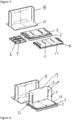
Figure 2 illustrates the shipper ofFigure 1 partly unpacked; -
Figure 3 illustrates a shipper ofFigures 1 and 2 after further unpacking; -
Figure 4 illustrates a shipper ofFigure 1 with an inner wall partly constructed; -
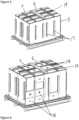
Figure 5 shows the shipper ofFigure 4 once the inner wall has been completed and the inner lid has been placed upon the shipper; -
Figure 6 illustrates the shipper ofFigure 5 once some of the cool packs have been placed around the inner wall; -
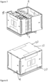
Figure 7 illustrates the outer wall being assembled on the shipper; -
Figure 8 illustrates the shipper with the outer lid in position and the shipper ready for shipment; -
Figure 9 is a cross-section through an edge protector used on the shipper ofFigures 1 to 8 ; -
Figure 10 is a cross-section through a cool pack retainer of the container ofFigures 1 to 8 ; -
Figure 11 is a cross-section through a corner post and hinge of the containers ofFigures 1 to 8 ; -
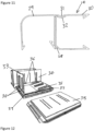
Figures 12 and13 illustrate an alternative configuration of inner structure for the container; and -
Figure 14 is cross section through an inner hinge assembly seen in embodiment ofFigures 12 and13 . - Referring to
Figure 1 there is illustrated a thermal insulated pallet shipping container "shipper" 1. The shipper 1 comprises apallet 2 on which is mounted abase 3. Loosely positioned on thebase 3 areinner wall sections inner lid outer wall section 8, which turn supports a further foldedouter wall section 9 and anouter lid 10. Theouter wall section 8 is strong enough to permit at least another 2 flat pack shippers to be stacked on the shipper 1 -
Figures 2 to 8 illustrate how the flat pack shipper 1 is first unpacked and then assembled ready for shipment. With reference toFigure 2 , theouter lid 10 andouter wall section 9 are first removed and placed to one side. Then, as shown inFigure 3 , the U-shapedouter wall section 8 andinner lid inner wall section 4, leaving the second foldedinner wall section 5 on thebase 3. - With reference to
Figure 4 , the secondinner wall section 5 is shown with innerside wall portions rear wall portion 13. These innerside wall portions hinges 14 and 15, only one of which is seen inFigure 4 . (Alternatively theinner wall section 5 could be made from a laminate foam board with the board being scored through from one side through one layer of laminate only, to form an in-built hinge). Regardless of the hinge construction, theinner wall section 4 ofFigure 3 can then be erected in a similar manner and positioned so that it abutsinner wall section 5, as shown inFigure 5 , with the bottom edges of theinner wall sections channel 16, seen inFigure 4 , ofbase 3. The container may be filled with a product (not shown) to be shipped when in the state illustrated inFigure 4 , especially if the product is itself on a pallet. The inner lid, comprising twosections Figure 5 , completing the inner structure of the shipper 1. Preassembled on theinner wall sections cool pack retainers 17. As shown with reference toFigure 6 , these receivecool packs 18 in a predetermined order. The cool packs may be either frozen, indicated by a "-" sign, or chilled, as indicated by a "+" sign. Once an appropriate number ofcool packs 18 have been inserted in theretainers 17 and placed inrecesses 19 ininner lid outer wall section 9 is infolded in the same manner as the previously described innerwall section s outer wall sections Figure 7 , prior toouter lid 10 being mounted on the top edge of theouter walls sections outer lid 10 andbase 3 have a number ofsmall PVC extrusions 20 that sit in the top surface of the outer lid and the bottom surface of the base to provide strapping points to secure the system and to prevent any damage to the outer lid or base. - Although it is not immediately apparent from the figures, the base and lid have the same outer edge stepped profile. Likewise the top and bottom edges of the
outer wall sections outer wall sections inner wall sections inner wall sections groove 16 in thebase 3 provided on the under surface ofinner lid inner wall sections - Referring to
Figures 9 to 11 there is shown in cross-section the profile of the extruded components used in the container 1 ofFigures 1 to 8 .Figure 9 shows the cross section of the strappingpoint extrusions 20 and it can be seen that this has two barb-like sections outer lid 10 orbase 3, which may typically be a low density expanded polystyrene. - Referring to
Figure 10 there is shown the cross-section of acool pack retainer 17. Again this has barb-like members retainer 17 engages withinner wall sections outer wall sections inner wall sections like members inner wall sections channels retainer 17 formed of PVC. The retainer17 is co-extruded and theend sections 27 are formed of a softer compound to avoid the possibility of injury when loading the cool packs. - Referring to
Figure 11 , there is shown the cross-section of one of the corner hinges 14. This is extruded from PVC and hingemember 28 permits thefirst section 29 to pivot relative to thesecond section 30. Anextension 31 to thefirst section 29 engages withrecess 32 in thesecond section 30 to lock wall sections mounted in the hinge 14 so that the wall sections extend perpendicularly away from each other. - Referring now to
Figure 12 , there is shown an alternative arrangement which may be used for the inner structure of the shipper ofFigure 1 to 8 . Here threesections hinges 36 to a base 37 and these may simply be raised to define a payload space into which a product can be loaded prior to thefinal section 38 being dropped into achannel 39 and aninner lid 40, with a similar channel being placed on the inner walls to complete the inner section of the shipper 1. The hinges 36 are shown in cross-section inFigure 14 . These are again formed from extruded PVC and are hinged byhinge member 42, the extruded hinge having alocking mechanism 43 identical to that described with reference toFigure 11 . - It will be appreciated that the present invention has been described by way of example only and that many alternative configurations and arrangements will be apparent to the person skilled in the art, which alternations and configurations may fall within the scope of the appended claims.
Claims (14)
- A thermally insulated shipping container (1) comprising:an inner structure including an inner base, a front inner wall, a rear inner wall opposed to the front inner wall, a pair of opposed side inner walls each extending between the front and rear inner walls and an inner lid (6, 7);an outer structure including an outer base, a front outer wall, a rear outer wall opposed to the front inner wall, two side outer walls each extending between the front and rear outer walls and an outer lid (10); anda cavity extending at least between the inner and outer walls, the cavity being arranged to receive a plurality of cool packs (18);wherein the container (1), when empty, is arranged to be transported disassembled in a flat packed state prior to being assembled for use, characterised in that, when disassembled, each side outer wall comprises a first portion and a second portion separate to the first portion, which first and second portions are arranged to abut together to form the respective side outer wall when the container is assembled for use, and in that the first portion of each of the two side outer walls is hinged at one end to a respective end of one of the front or rear outer walls.
- A container as claimed in Claim 1, wherein each said first portion of the side outer wall is hinged to a respective end of the front outer wall and can be folded flat against the front outer wall or each said first portion of the side outer wall is hinged to a respective end of the rear outer wall and can be folded flat against the rear outer wall.
- A container as claimed in Claim 2, wherein each said first portion of the side outer wall is hinged to a respective end of the front outer wall and can be folded flat against the front outer wall, and wherein each said second portion of each side outer wall is joined substantially at right angles to respective ends of the rear outer wall to form a U-shaped outer wall section (8).
- A container as claimed in Claim 3, wherein the inner lid (6, 7), rear inner wall, front inner wall and side inner walls are arranged so that they can be stacked flat upon the inner base, wherein the lengths of the two second portions of the two side outer walls are sufficient that when the inner base is on the outer base and the remaining components of the inner structure are stacked flat upon the inner base, the U-shaped outer wall section (8) may be placed inverted on the outer base such that it bridges over the components of the inner structure, whereby the front outer wall with first portions of the side outer wall folded flat against it, may be placed on and supported by the U-shaped outer wall section (8).
- A container as claimed in Claim 4, wherein all the components of the container are attached and arranged such that the container may be transported in a flat packed state without the need to package the container in a sleeve.
- A container as claimed in any one of Claims 3 to 5, wherein the height of the outer walls is between 80 to 100 percent of the length of one side of the container, such that the U-shaped outer wall section may be positioned over 80 to 100 percent of the outer base.
- A container as claimed in any preceding claim, wherein the inner base and outer base are formed from a common component (3).
- A container as claimed in any preceding claim, wherein the inner structure is arranged such that the inner walls may be positioned around the edge of the inner base and the inner lid (6, 7) placed on top of the inner walls to define a payload space within the inner structure, the components of the inner structure being arranged to engage with each other such that the inner structure is self-supporting.
- A container as claimed in Claim 8 wherein at least two of the front inner wall, rear inner wall and two inner side walls are hinged to the inner base so that they may be folded from a flat state, where they lie substantially flat over the inner base to a vertical position.
- A container as claimed in Claim 9, wherein at least three of the front inner wall, rear inner wall and two inner side walls are hinged to the inner base so that they may be folded from a flat state where they lie substantially flat over the inner base to a vertical position.
- A container as claimed in any one of Claims 1 to 8, wherein a portion of each of the two side inner walls is hinged at one end to a respective end of the front or rear inner walls.
- A container as claimed in any preceding claim, wherein a plurality of retainers (17) are secured to the outer surfaces of the inner walls, which retainers (17) are arranged to retain a plurality of cool packs (18) in place prior to and after the outer walls being positioned in place.
- A container as claimed in Claim 12, wherein the retainers (17) are extruded channels.
- A container as claimed in Claim 12 or 13, wherein the retainers (17) are formed from two co-extruded materials, with the edges of the retainers (17) formed of a softer material than the central regions of the retainers (17).
Applications Claiming Priority (3)
| Application Number | Priority Date | Filing Date | Title |
|---|---|---|---|
| GB1221629.7A GB2508415B (en) | 2012-11-30 | 2012-11-30 | A thermally insulated shipping container |
| EP13799632.8A EP2925630B1 (en) | 2012-11-30 | 2013-11-25 | A thermally insulated shipping container |
| PCT/GB2013/053097 WO2014083320A1 (en) | 2012-11-30 | 2013-11-25 | A thermally insulated shipping container |
Related Parent Applications (2)
| Application Number | Title | Priority Date | Filing Date |
|---|---|---|---|
| EP13799632.8A Division EP2925630B1 (en) | 2012-11-30 | 2013-11-25 | A thermally insulated shipping container |
| EP13799632.8A Division-Into EP2925630B1 (en) | 2012-11-30 | 2013-11-25 | A thermally insulated shipping container |
Publications (2)
| Publication Number | Publication Date |
|---|---|
| EP3778424A1 EP3778424A1 (en) | 2021-02-17 |
| EP3778424B1 true EP3778424B1 (en) | 2023-12-20 |
Family
ID=49713388
Family Applications (2)
| Application Number | Title | Priority Date | Filing Date |
|---|---|---|---|
| EP20198181.8A Active EP3778424B1 (en) | 2012-11-30 | 2013-11-25 | A thermally insulated shipping container |
| EP13799632.8A Active EP2925630B1 (en) | 2012-11-30 | 2013-11-25 | A thermally insulated shipping container |
Family Applications After (1)
| Application Number | Title | Priority Date | Filing Date |
|---|---|---|---|
| EP13799632.8A Active EP2925630B1 (en) | 2012-11-30 | 2013-11-25 | A thermally insulated shipping container |
Country Status (7)
| Country | Link |
|---|---|
| US (1) | US10000329B2 (en) |
| EP (2) | EP3778424B1 (en) |
| BR (1) | BR112015010546A2 (en) |
| ES (2) | ES2974448T3 (en) |
| GB (2) | GB2508415B (en) |
| HK (1) | HK1198712A1 (en) |
| WO (1) | WO2014083320A1 (en) |
Families Citing this family (27)
| Publication number | Priority date | Publication date | Assignee | Title |
|---|---|---|---|---|
| EP2200904B1 (en) | 2007-09-11 | 2013-06-26 | Cold Chain Technologies, Inc. | Insulated pallet shipper |
| GB2508415B (en) | 2012-11-30 | 2017-02-01 | Laminar Medica Ltd | A thermally insulated shipping container |
| GB2530077A (en) * | 2014-09-12 | 2016-03-16 | Peli Biothermal Ltd | Thermally insulated containers |
| US10011418B2 (en) | 2014-09-26 | 2018-07-03 | Pelican Biothermal Llc | High efficiency bolt-on thermal insulating panel and thermally insulated shipping container employing such a thermal insulating panel |
| US11964795B2 (en) | 2015-10-06 | 2024-04-23 | Cold Chain Technologies, Llc | Device comprising one or more temperature-control members and kit for use in making the device |
| CA3001048C (en) | 2015-10-06 | 2020-11-24 | Cold Chain Technologies, Inc. | Pallet cover comprising one or more temperature-control members and kit for use in making the pallet cover |
| WO2017062692A1 (en) | 2015-10-06 | 2017-04-13 | Cold Chain Technologies,Inc. | Thermally insulated shipping system for pallet-sized payload, methods of making and using the same, and kit for use therein |
| US11591133B2 (en) | 2015-10-06 | 2023-02-28 | Cold Chain Technologies, Llc | Pallet cover comprising one or more temperature-control members and kit for use in making the pallet cover |
| US10583978B2 (en) | 2015-10-06 | 2020-03-10 | Cold Chain Technologies, Llc | Pallet cover compromising one or more temperature-control members and kit for use in making the pallet cover |
| US10919665B2 (en) * | 2016-10-06 | 2021-02-16 | Viking Cold Solutions, Inc. | Pallet with thermal energy storage |
| US10443918B2 (en) | 2017-05-18 | 2019-10-15 | Otter Products, Llc | Configurable insulated storage container |
| US10906723B2 (en) | 2017-06-05 | 2021-02-02 | Otter Products, Llc | Collapsible portable storage container |
| US11999559B2 (en) | 2018-08-10 | 2024-06-04 | Cold Chain Technologies, Llc | Apparatus and method for protectively covering temperature sensitive products |
| US11267621B2 (en) | 2018-09-27 | 2022-03-08 | Otter Products, Llc | Storage container and floating latch |
| US11161678B2 (en) | 2018-11-27 | 2021-11-02 | Otter Products, Llc | Portable storage container |
| USD912400S1 (en) | 2019-02-08 | 2021-03-09 | Otter Products, Llc | Container |
| USD908357S1 (en) | 2019-02-08 | 2021-01-26 | Otter Products, Llc | Container |
| US11377290B2 (en) | 2019-07-15 | 2022-07-05 | Otter Products, Llc | Portable insulated container |
| US11242175B2 (en) | 2019-08-21 | 2022-02-08 | Otter Products, Llc | Configurable container |
| US11267637B2 (en) | 2019-08-21 | 2022-03-08 | Otter Products, Llc | Configurable container |
| WO2021046491A1 (en) | 2019-09-05 | 2021-03-11 | Cold Chain Technologies, Llc | Shipping system for temperature-sensitive materials |
| GB2596806A (en) * | 2020-07-06 | 2022-01-12 | I Boxit Ltd | Methods and apparatus for packaging |
| EP4292954A4 (en) * | 2021-02-10 | 2025-03-19 | Kaneka Corporation | CONSTANT TEMPERATURE TRANSPORT CONTAINER AND CONSTANT TEMPERATURE TRANSPORT CONTAINER ARRANGEMENT |
| CN113859746A (en) * | 2021-10-20 | 2021-12-31 | 宁波一象吹塑家具有限公司 | Storage box and packaging structure thereof |
| USD996059S1 (en) | 2022-02-24 | 2023-08-22 | Otter Products, Llc | Container |
| US12292229B2 (en) * | 2023-01-24 | 2025-05-06 | Epazz, Inc | Foldable refrigerator |
| GB202411886D0 (en) * | 2024-08-12 | 2024-09-25 | Anderson Marcus Julian Peter | A cold chain shipper and temperature control system |
Family Cites Families (30)
| Publication number | Priority date | Publication date | Assignee | Title |
|---|---|---|---|---|
| US649222A (en) | 1900-02-26 | 1900-05-08 | Archibald G Smith | Box. |
| US3784043A (en) | 1968-11-29 | 1974-01-08 | M Presnick | Lightweight collapsible structures |
| US3765556A (en) | 1969-09-11 | 1973-10-16 | Allied Prod Corp | Collapsible shipping container |
| US4606461A (en) * | 1985-04-18 | 1986-08-19 | Ace Paper Products Co. | Collapsible container |
| US5215248A (en) * | 1988-12-29 | 1993-06-01 | Hexacomb Corporation | Collapsible shipping carton |
| US5076457A (en) * | 1989-06-22 | 1991-12-31 | Tetra Pak Holdings S.A. | Folding crate for holding packages |
| US5199589A (en) * | 1992-07-27 | 1993-04-06 | Noble William L | Collapsible bix box assembly formed of two separate collapsible bin boxes |
| JPH07187183A (en) * | 1993-12-24 | 1995-07-25 | Tomiyuki Hirota | Collapsible container |
| US5601202A (en) * | 1994-01-06 | 1997-02-11 | Temp Top Container Systems, Inc. | Transport chamber |
| GB2293160B (en) * | 1994-09-15 | 1997-12-10 | Lin Pac Mouldings | A frame and a container having upstanding side walls provided by the frame |
| US5669233A (en) * | 1996-03-11 | 1997-09-23 | Tcp Reliable Inc. | Collapsible and reusable shipping container |
| JPH107186A (en) * | 1996-06-18 | 1998-01-13 | Showa Aircraft Ind Co Ltd | Foldable container |
| US5829595A (en) * | 1997-03-03 | 1998-11-03 | Trienda Corporation | Thin sheet thermoformed pallet sleeve |
| JPH10324332A (en) * | 1997-05-23 | 1998-12-08 | Nikko Chem Kk | Folding container |
| WO1999032374A1 (en) * | 1997-12-19 | 1999-07-01 | Federal Express Corporation | Insulated shipping container |
| US5979693A (en) * | 1997-12-29 | 1999-11-09 | Bane, Iii; William W. | Panel for shipping containers |
| US6325281B1 (en) * | 2000-03-30 | 2001-12-04 | Polyfoam Packers Corporation | Thermally insulating shipping system |
| US6752285B1 (en) | 2002-04-08 | 2004-06-22 | Wallace J. Scalf | Storage and shipping bin |
| DE102005013263A1 (en) | 2005-03-18 | 2006-09-21 | Achilles Präsentationsprodukte GmbH | Carton comprises rectangular box with open top, flaps consisting of triangular sections of box being attached by their points to base of box and swiveling so that their tops cover open top of box |
| WO2007033051A2 (en) * | 2005-09-12 | 2007-03-22 | Genzyme Corporation | Thermally insulated transport container for cell-based products and related methods |
| EP1996053B1 (en) * | 2006-03-02 | 2015-12-30 | Cold Chain Technologies, Inc. | Insulated shipping container and method of making the same |
| WO2008122074A1 (en) | 2007-04-05 | 2008-10-16 | Smartcage Pty Ltd | Intermodal air cargo containers |
| JP2008265795A (en) * | 2007-04-18 | 2008-11-06 | Watanabe Kogyosho:Kk | Container |
| EP2142431A4 (en) * | 2007-05-04 | 2014-06-18 | Entropy Solutions Inc | Package having phase change materials and method of use in transport of temperature sensitive payload |
| EP2200904B1 (en) | 2007-09-11 | 2013-06-26 | Cold Chain Technologies, Inc. | Insulated pallet shipper |
| EP2053325A1 (en) * | 2007-10-23 | 2009-04-29 | Deutsche Post AG | Collapsible container package; method for packing temperature sensitive goods and container pooling system |
| US8919082B1 (en) * | 2009-06-15 | 2014-12-30 | Iowa E. P. S. Products, Inc. | Collapsible foam shipping cooler for perishables and method of making |
| US8424335B2 (en) * | 2009-12-17 | 2013-04-23 | Minnesota Thermal Science, Llc | Cascading series of thermally insulated passive temperature controlled containers |
| US20130228583A1 (en) * | 2012-03-02 | 2013-09-05 | William T. Mayer | Passive thermally regulated knockdown shipping container |
| GB2508415B (en) | 2012-11-30 | 2017-02-01 | Laminar Medica Ltd | A thermally insulated shipping container |
-
2012
- 2012-11-30 GB GB1221629.7A patent/GB2508415B/en active Active
- 2012-11-30 GB GB1613718.4A patent/GB2538892B/en active Active
-
2013
- 2013-11-25 EP EP20198181.8A patent/EP3778424B1/en active Active
- 2013-11-25 ES ES20198181T patent/ES2974448T3/en active Active
- 2013-11-25 EP EP13799632.8A patent/EP2925630B1/en active Active
- 2013-11-25 WO PCT/GB2013/053097 patent/WO2014083320A1/en not_active Ceased
- 2013-11-25 BR BR112015010546A patent/BR112015010546A2/en not_active IP Right Cessation
- 2013-11-25 ES ES13799632T patent/ES2855011T3/en active Active
- 2013-11-25 US US14/648,421 patent/US10000329B2/en active Active
-
2014
- 2014-12-02 HK HK14112146.2A patent/HK1198712A1/en unknown
Also Published As
| Publication number | Publication date |
|---|---|
| EP3778424A1 (en) | 2021-02-17 |
| GB2538892A (en) | 2016-11-30 |
| GB2508415A (en) | 2014-06-04 |
| US10000329B2 (en) | 2018-06-19 |
| EP2925630B1 (en) | 2020-11-25 |
| WO2014083320A1 (en) | 2014-06-05 |
| ES2974448T3 (en) | 2024-06-27 |
| EP2925630A1 (en) | 2015-10-07 |
| HK1198712A1 (en) | 2015-05-29 |
| ES2855011T3 (en) | 2021-09-23 |
| US20150298886A1 (en) | 2015-10-22 |
| GB2508415B (en) | 2017-02-01 |
| GB2538892B (en) | 2017-05-31 |
| BR112015010546A2 (en) | 2017-07-11 |
Similar Documents
| Publication | Publication Date | Title |
|---|---|---|
| EP2925630B1 (en) | A thermally insulated shipping container | |
| EP2256065B1 (en) | Thermally insulating transport container | |
| US8250835B2 (en) | Thermally insulated, collapsible cover assembly and method of using to transport perishable produce | |
| US20140091098A1 (en) | Isothermal packaging device for heat-sensitive products | |
| KR20210041064A (en) | Vacuum-insulated laminated container for temperature-controlled transportation of food | |
| US20100147840A1 (en) | Reusable, Combined Multi-Part Product Shipping Box and Display Tray | |
| US20090175700A1 (en) | Cargo shipping assembly and method | |
| CN1138846A (en) | Insulating foldable box for transportation and packaging purposes | |
| BR112012016234B1 (en) | Modular packaging system and method | |
| CN107250001A (en) | Corner fittings for packaging | |
| US20170113863A1 (en) | Reusable modular containment device for protecting cargo during shipment | |
| US12103733B2 (en) | Two-piece vibration dampening pallet assembly | |
| JP3177764U (en) | Wooden box for packing transportation | |
| JP7546575B2 (en) | Box support, box packaging method, and box transportation method | |
| KR101742381B1 (en) | Container pallet for easy stacking | |
| US20090184113A1 (en) | Packing crate assembly | |
| JP4181726B2 (en) | Roll product shipping container | |
| KR20180109008A (en) | a packing container with frame | |
| CA2404245A1 (en) | Collapsible transport container | |
| CN101578222A (en) | Pallet |
Legal Events
| Date | Code | Title | Description |
|---|---|---|---|
| PUAI | Public reference made under article 153(3) epc to a published international application that has entered the european phase |
Free format text: ORIGINAL CODE: 0009012 |
|
| STAA | Information on the status of an ep patent application or granted ep patent |
Free format text: STATUS: REQUEST FOR EXAMINATION WAS MADE |
|
| 17P | Request for examination filed |
Effective date: 20200924 |
|
| AC | Divisional application: reference to earlier application |
Ref document number: 2925630 Country of ref document: EP Kind code of ref document: P |
|
| AK | Designated contracting states |
Kind code of ref document: A1 Designated state(s): AL AT BE BG CH CY CZ DE DK EE ES FI FR GB GR HR HU IE IS IT LI LT LU LV MC MK MT NL NO PL PT RO RS SE SI SK SM TR |
|
| P01 | Opt-out of the competence of the unified patent court (upc) registered |
Effective date: 20230519 |
|
| GRAP | Despatch of communication of intention to grant a patent |
Free format text: ORIGINAL CODE: EPIDOSNIGR1 |
|
| STAA | Information on the status of an ep patent application or granted ep patent |
Free format text: STATUS: GRANT OF PATENT IS INTENDED |
|
| INTG | Intention to grant announced |
Effective date: 20230705 |
|
| GRAS | Grant fee paid |
Free format text: ORIGINAL CODE: EPIDOSNIGR3 |
|
| RBV | Designated contracting states (corrected) |
Designated state(s): AL AT BE BG CH CY CZ DE DK EE ES FI FR GR HR HU IE IS IT LI LT LU LV MC MK MT NL NO PL PT RO RS SE SI SK SM TR |
|
| GRAA | (expected) grant |
Free format text: ORIGINAL CODE: 0009210 |
|
| STAA | Information on the status of an ep patent application or granted ep patent |
Free format text: STATUS: THE PATENT HAS BEEN GRANTED |
|
| AC | Divisional application: reference to earlier application |
Ref document number: 2925630 Country of ref document: EP Kind code of ref document: P |
|
| AK | Designated contracting states |
Kind code of ref document: B1 Designated state(s): AL AT BE BG CH CY CZ DE DK EE ES FI FR GR HR HU IE IS IT LI LT LU LV MC MK MT NL NO PL PT RO RS SE SI SK SM TR |
|
| REG | Reference to a national code |
Ref country code: DE Ref legal event code: R096 Ref document number: 602013085102 Country of ref document: DE |
|
| REG | Reference to a national code |
Ref country code: CH Ref legal event code: EP |
|
| REG | Reference to a national code |
Ref country code: IE Ref legal event code: FG4D |
|
| PG25 | Lapsed in a contracting state [announced via postgrant information from national office to epo] |
Ref country code: GR Free format text: LAPSE BECAUSE OF FAILURE TO SUBMIT A TRANSLATION OF THE DESCRIPTION OR TO PAY THE FEE WITHIN THE PRESCRIBED TIME-LIMIT Effective date: 20240321 |
|
| REG | Reference to a national code |
Ref country code: LT Ref legal event code: MG9D |
|
| PG25 | Lapsed in a contracting state [announced via postgrant information from national office to epo] |
Ref country code: LT Free format text: LAPSE BECAUSE OF FAILURE TO SUBMIT A TRANSLATION OF THE DESCRIPTION OR TO PAY THE FEE WITHIN THE PRESCRIBED TIME-LIMIT Effective date: 20231220 |
|
| REG | Reference to a national code |
Ref country code: NL Ref legal event code: MP Effective date: 20231220 |
|
| PG25 | Lapsed in a contracting state [announced via postgrant information from national office to epo] |
Ref country code: LT Free format text: LAPSE BECAUSE OF FAILURE TO SUBMIT A TRANSLATION OF THE DESCRIPTION OR TO PAY THE FEE WITHIN THE PRESCRIBED TIME-LIMIT Effective date: 20231220 Ref country code: GR Free format text: LAPSE BECAUSE OF FAILURE TO SUBMIT A TRANSLATION OF THE DESCRIPTION OR TO PAY THE FEE WITHIN THE PRESCRIBED TIME-LIMIT Effective date: 20240321 Ref country code: FI Free format text: LAPSE BECAUSE OF FAILURE TO SUBMIT A TRANSLATION OF THE DESCRIPTION OR TO PAY THE FEE WITHIN THE PRESCRIBED TIME-LIMIT Effective date: 20231220 Ref country code: BG Free format text: LAPSE BECAUSE OF FAILURE TO SUBMIT A TRANSLATION OF THE DESCRIPTION OR TO PAY THE FEE WITHIN THE PRESCRIBED TIME-LIMIT Effective date: 20240320 |
|
| REG | Reference to a national code |
Ref country code: AT Ref legal event code: MK05 Ref document number: 1642295 Country of ref document: AT Kind code of ref document: T Effective date: 20231220 |
|
| PG25 | Lapsed in a contracting state [announced via postgrant information from national office to epo] |
Ref country code: NL Free format text: LAPSE BECAUSE OF FAILURE TO SUBMIT A TRANSLATION OF THE DESCRIPTION OR TO PAY THE FEE WITHIN THE PRESCRIBED TIME-LIMIT Effective date: 20231220 |
|
| PG25 | Lapsed in a contracting state [announced via postgrant information from national office to epo] |
Ref country code: SE Free format text: LAPSE BECAUSE OF FAILURE TO SUBMIT A TRANSLATION OF THE DESCRIPTION OR TO PAY THE FEE WITHIN THE PRESCRIBED TIME-LIMIT Effective date: 20231220 Ref country code: RS Free format text: LAPSE BECAUSE OF FAILURE TO SUBMIT A TRANSLATION OF THE DESCRIPTION OR TO PAY THE FEE WITHIN THE PRESCRIBED TIME-LIMIT Effective date: 20231220 Ref country code: NO Free format text: LAPSE BECAUSE OF FAILURE TO SUBMIT A TRANSLATION OF THE DESCRIPTION OR TO PAY THE FEE WITHIN THE PRESCRIBED TIME-LIMIT Effective date: 20240320 Ref country code: NL Free format text: LAPSE BECAUSE OF FAILURE TO SUBMIT A TRANSLATION OF THE DESCRIPTION OR TO PAY THE FEE WITHIN THE PRESCRIBED TIME-LIMIT Effective date: 20231220 Ref country code: LV Free format text: LAPSE BECAUSE OF FAILURE TO SUBMIT A TRANSLATION OF THE DESCRIPTION OR TO PAY THE FEE WITHIN THE PRESCRIBED TIME-LIMIT Effective date: 20231220 Ref country code: HR Free format text: LAPSE BECAUSE OF FAILURE TO SUBMIT A TRANSLATION OF THE DESCRIPTION OR TO PAY THE FEE WITHIN THE PRESCRIBED TIME-LIMIT Effective date: 20231220 |
|
| REG | Reference to a national code |
Ref country code: ES Ref legal event code: FG2A Ref document number: 2974448 Country of ref document: ES Kind code of ref document: T3 Effective date: 20240627 |
|
| PG25 | Lapsed in a contracting state [announced via postgrant information from national office to epo] |
Ref country code: IS Free format text: LAPSE BECAUSE OF FAILURE TO SUBMIT A TRANSLATION OF THE DESCRIPTION OR TO PAY THE FEE WITHIN THE PRESCRIBED TIME-LIMIT Effective date: 20240420 |
|
| PG25 | Lapsed in a contracting state [announced via postgrant information from national office to epo] |
Ref country code: AT Free format text: LAPSE BECAUSE OF FAILURE TO SUBMIT A TRANSLATION OF THE DESCRIPTION OR TO PAY THE FEE WITHIN THE PRESCRIBED TIME-LIMIT Effective date: 20231220 Ref country code: CZ Free format text: LAPSE BECAUSE OF FAILURE TO SUBMIT A TRANSLATION OF THE DESCRIPTION OR TO PAY THE FEE WITHIN THE PRESCRIBED TIME-LIMIT Effective date: 20231220 |
|
| PG25 | Lapsed in a contracting state [announced via postgrant information from national office to epo] |
Ref country code: SK Free format text: LAPSE BECAUSE OF FAILURE TO SUBMIT A TRANSLATION OF THE DESCRIPTION OR TO PAY THE FEE WITHIN THE PRESCRIBED TIME-LIMIT Effective date: 20231220 |
|
| PG25 | Lapsed in a contracting state [announced via postgrant information from national office to epo] |
Ref country code: SM Free format text: LAPSE BECAUSE OF FAILURE TO SUBMIT A TRANSLATION OF THE DESCRIPTION OR TO PAY THE FEE WITHIN THE PRESCRIBED TIME-LIMIT Effective date: 20231220 Ref country code: SK Free format text: LAPSE BECAUSE OF FAILURE TO SUBMIT A TRANSLATION OF THE DESCRIPTION OR TO PAY THE FEE WITHIN THE PRESCRIBED TIME-LIMIT Effective date: 20231220 Ref country code: RO Free format text: LAPSE BECAUSE OF FAILURE TO SUBMIT A TRANSLATION OF THE DESCRIPTION OR TO PAY THE FEE WITHIN THE PRESCRIBED TIME-LIMIT Effective date: 20231220 Ref country code: IS Free format text: LAPSE BECAUSE OF FAILURE TO SUBMIT A TRANSLATION OF THE DESCRIPTION OR TO PAY THE FEE WITHIN THE PRESCRIBED TIME-LIMIT Effective date: 20240420 Ref country code: EE Free format text: LAPSE BECAUSE OF FAILURE TO SUBMIT A TRANSLATION OF THE DESCRIPTION OR TO PAY THE FEE WITHIN THE PRESCRIBED TIME-LIMIT Effective date: 20231220 Ref country code: CZ Free format text: LAPSE BECAUSE OF FAILURE TO SUBMIT A TRANSLATION OF THE DESCRIPTION OR TO PAY THE FEE WITHIN THE PRESCRIBED TIME-LIMIT Effective date: 20231220 Ref country code: AT Free format text: LAPSE BECAUSE OF FAILURE TO SUBMIT A TRANSLATION OF THE DESCRIPTION OR TO PAY THE FEE WITHIN THE PRESCRIBED TIME-LIMIT Effective date: 20231220 |
|
| PG25 | Lapsed in a contracting state [announced via postgrant information from national office to epo] |
Ref country code: PL Free format text: LAPSE BECAUSE OF FAILURE TO SUBMIT A TRANSLATION OF THE DESCRIPTION OR TO PAY THE FEE WITHIN THE PRESCRIBED TIME-LIMIT Effective date: 20231220 Ref country code: PT Free format text: LAPSE BECAUSE OF FAILURE TO SUBMIT A TRANSLATION OF THE DESCRIPTION OR TO PAY THE FEE WITHIN THE PRESCRIBED TIME-LIMIT Effective date: 20240422 |
|
| PG25 | Lapsed in a contracting state [announced via postgrant information from national office to epo] |
Ref country code: PT Free format text: LAPSE BECAUSE OF FAILURE TO SUBMIT A TRANSLATION OF THE DESCRIPTION OR TO PAY THE FEE WITHIN THE PRESCRIBED TIME-LIMIT Effective date: 20240422 Ref country code: PL Free format text: LAPSE BECAUSE OF FAILURE TO SUBMIT A TRANSLATION OF THE DESCRIPTION OR TO PAY THE FEE WITHIN THE PRESCRIBED TIME-LIMIT Effective date: 20231220 |
|
| REG | Reference to a national code |
Ref country code: DE Ref legal event code: R097 Ref document number: 602013085102 Country of ref document: DE |
|
| PG25 | Lapsed in a contracting state [announced via postgrant information from national office to epo] |
Ref country code: DK Free format text: LAPSE BECAUSE OF FAILURE TO SUBMIT A TRANSLATION OF THE DESCRIPTION OR TO PAY THE FEE WITHIN THE PRESCRIBED TIME-LIMIT Effective date: 20231220 |
|
| PLBE | No opposition filed within time limit |
Free format text: ORIGINAL CODE: 0009261 |
|
| STAA | Information on the status of an ep patent application or granted ep patent |
Free format text: STATUS: NO OPPOSITION FILED WITHIN TIME LIMIT |
|
| PG25 | Lapsed in a contracting state [announced via postgrant information from national office to epo] |
Ref country code: SI Free format text: LAPSE BECAUSE OF FAILURE TO SUBMIT A TRANSLATION OF THE DESCRIPTION OR TO PAY THE FEE WITHIN THE PRESCRIBED TIME-LIMIT Effective date: 20231220 |
|
| PG25 | Lapsed in a contracting state [announced via postgrant information from national office to epo] |
Ref country code: SI Free format text: LAPSE BECAUSE OF FAILURE TO SUBMIT A TRANSLATION OF THE DESCRIPTION OR TO PAY THE FEE WITHIN THE PRESCRIBED TIME-LIMIT Effective date: 20231220 Ref country code: DK Free format text: LAPSE BECAUSE OF FAILURE TO SUBMIT A TRANSLATION OF THE DESCRIPTION OR TO PAY THE FEE WITHIN THE PRESCRIBED TIME-LIMIT Effective date: 20231220 |
|
| 26N | No opposition filed |
Effective date: 20240923 |
|
| PGFP | Annual fee paid to national office [announced via postgrant information from national office to epo] |
Ref country code: DE Payment date: 20241127 Year of fee payment: 12 |
|
| PGFP | Annual fee paid to national office [announced via postgrant information from national office to epo] |
Ref country code: FR Payment date: 20241128 Year of fee payment: 12 |
|
| PGFP | Annual fee paid to national office [announced via postgrant information from national office to epo] |
Ref country code: ES Payment date: 20241202 Year of fee payment: 12 |
|
| REG | Reference to a national code |
Ref country code: CH Ref legal event code: PL |
|
| PG25 | Lapsed in a contracting state [announced via postgrant information from national office to epo] |
Ref country code: MC Free format text: LAPSE BECAUSE OF FAILURE TO SUBMIT A TRANSLATION OF THE DESCRIPTION OR TO PAY THE FEE WITHIN THE PRESCRIBED TIME-LIMIT Effective date: 20231220 |
|
| PG25 | Lapsed in a contracting state [announced via postgrant information from national office to epo] |
Ref country code: LU Free format text: LAPSE BECAUSE OF NON-PAYMENT OF DUE FEES Effective date: 20241125 |
|
| REG | Reference to a national code |
Ref country code: CH Ref legal event code: PL |
|
| PG25 | Lapsed in a contracting state [announced via postgrant information from national office to epo] |
Ref country code: CH Free format text: LAPSE BECAUSE OF NON-PAYMENT OF DUE FEES Effective date: 20241130 |
|
| REG | Reference to a national code |
Ref country code: BE Ref legal event code: MM Effective date: 20241130 |
|
| PG25 | Lapsed in a contracting state [announced via postgrant information from national office to epo] |
Ref country code: BE Free format text: LAPSE BECAUSE OF NON-PAYMENT OF DUE FEES Effective date: 20241130 |
|
| PG25 | Lapsed in a contracting state [announced via postgrant information from national office to epo] |
Ref country code: IE Free format text: LAPSE BECAUSE OF NON-PAYMENT OF DUE FEES Effective date: 20241125 |
|
| PGFP | Annual fee paid to national office [announced via postgrant information from national office to epo] |
Ref country code: IT Payment date: 20251119 Year of fee payment: 13 |
|
| PG25 | Lapsed in a contracting state [announced via postgrant information from national office to epo] |
Ref country code: HU Free format text: LAPSE BECAUSE OF FAILURE TO SUBMIT A TRANSLATION OF THE DESCRIPTION OR TO PAY THE FEE WITHIN THE PRESCRIBED TIME-LIMIT; INVALID AB INITIO Effective date: 20131125 |
|
| PG25 | Lapsed in a contracting state [announced via postgrant information from national office to epo] |
Ref country code: CY Free format text: LAPSE BECAUSE OF FAILURE TO SUBMIT A TRANSLATION OF THE DESCRIPTION OR TO PAY THE FEE WITHIN THE PRESCRIBED TIME-LIMIT; INVALID AB INITIO Effective date: 20131125 |