EP3778414A1 - Can lid - Google Patents
Can lid Download PDFInfo
- Publication number
- EP3778414A1 EP3778414A1 EP19780785.2A EP19780785A EP3778414A1 EP 3778414 A1 EP3778414 A1 EP 3778414A1 EP 19780785 A EP19780785 A EP 19780785A EP 3778414 A1 EP3778414 A1 EP 3778414A1
- Authority
- EP
- European Patent Office
- Prior art keywords
- lid
- tab
- slope
- center
- panel surface
- Prior art date
- Legal status (The legal status is an assumption and is not a legal conclusion. Google has not performed a legal analysis and makes no representation as to the accuracy of the status listed.)
- Withdrawn
Links
Images




Classifications
-
- B—PERFORMING OPERATIONS; TRANSPORTING
- B65—CONVEYING; PACKING; STORING; HANDLING THIN OR FILAMENTARY MATERIAL
- B65D—CONTAINERS FOR STORAGE OR TRANSPORT OF ARTICLES OR MATERIALS, e.g. BAGS, BARRELS, BOTTLES, BOXES, CANS, CARTONS, CRATES, DRUMS, JARS, TANKS, HOPPERS, FORWARDING CONTAINERS; ACCESSORIES, CLOSURES, OR FITTINGS THEREFOR; PACKAGING ELEMENTS; PACKAGES
- B65D17/00—Rigid or semi-rigid containers specially constructed to be opened by cutting or piercing, or by tearing of frangible members or portions
- B65D17/28—Rigid or semi-rigid containers specially constructed to be opened by cutting or piercing, or by tearing of frangible members or portions at lines or points of weakness
- B65D17/34—Arrangement or construction of pull or lift tabs
-
- B—PERFORMING OPERATIONS; TRANSPORTING
- B65—CONVEYING; PACKING; STORING; HANDLING THIN OR FILAMENTARY MATERIAL
- B65D—CONTAINERS FOR STORAGE OR TRANSPORT OF ARTICLES OR MATERIALS, e.g. BAGS, BARRELS, BOTTLES, BOXES, CANS, CARTONS, CRATES, DRUMS, JARS, TANKS, HOPPERS, FORWARDING CONTAINERS; ACCESSORIES, CLOSURES, OR FITTINGS THEREFOR; PACKAGING ELEMENTS; PACKAGES
- B65D17/00—Rigid or semi-rigid containers specially constructed to be opened by cutting or piercing, or by tearing of frangible members or portions
- B65D17/28—Rigid or semi-rigid containers specially constructed to be opened by cutting or piercing, or by tearing of frangible members or portions at lines or points of weakness
- B65D17/401—Rigid or semi-rigid containers specially constructed to be opened by cutting or piercing, or by tearing of frangible members or portions at lines or points of weakness characterised by having the line of weakness provided in an end wall
- B65D17/4012—Rigid or semi-rigid containers specially constructed to be opened by cutting or piercing, or by tearing of frangible members or portions at lines or points of weakness characterised by having the line of weakness provided in an end wall for opening partially by means of a tearing tab
-
- B—PERFORMING OPERATIONS; TRANSPORTING
- B65—CONVEYING; PACKING; STORING; HANDLING THIN OR FILAMENTARY MATERIAL
- B65D—CONTAINERS FOR STORAGE OR TRANSPORT OF ARTICLES OR MATERIALS, e.g. BAGS, BARRELS, BOTTLES, BOXES, CANS, CARTONS, CRATES, DRUMS, JARS, TANKS, HOPPERS, FORWARDING CONTAINERS; ACCESSORIES, CLOSURES, OR FITTINGS THEREFOR; PACKAGING ELEMENTS; PACKAGES
- B65D2517/00—Containers specially constructed to be opened by cutting, piercing or tearing of wall portions, e.g. preserving cans or tins
- B65D2517/0001—Details
- B65D2517/001—Action for opening container
- B65D2517/0013—Action for opening container pull-out tear panel, e.g. by means of a tear-tab
-
- B—PERFORMING OPERATIONS; TRANSPORTING
- B65—CONVEYING; PACKING; STORING; HANDLING THIN OR FILAMENTARY MATERIAL
- B65D—CONTAINERS FOR STORAGE OR TRANSPORT OF ARTICLES OR MATERIALS, e.g. BAGS, BARRELS, BOTTLES, BOXES, CANS, CARTONS, CRATES, DRUMS, JARS, TANKS, HOPPERS, FORWARDING CONTAINERS; ACCESSORIES, CLOSURES, OR FITTINGS THEREFOR; PACKAGING ELEMENTS; PACKAGES
- B65D2517/00—Containers specially constructed to be opened by cutting, piercing or tearing of wall portions, e.g. preserving cans or tins
- B65D2517/0001—Details
- B65D2517/001—Action for opening container
- B65D2517/0014—Action for opening container pivot tab and push-down tear panel
-
- B—PERFORMING OPERATIONS; TRANSPORTING
- B65—CONVEYING; PACKING; STORING; HANDLING THIN OR FILAMENTARY MATERIAL
- B65D—CONTAINERS FOR STORAGE OR TRANSPORT OF ARTICLES OR MATERIALS, e.g. BAGS, BARRELS, BOTTLES, BOXES, CANS, CARTONS, CRATES, DRUMS, JARS, TANKS, HOPPERS, FORWARDING CONTAINERS; ACCESSORIES, CLOSURES, OR FITTINGS THEREFOR; PACKAGING ELEMENTS; PACKAGES
- B65D2517/00—Containers specially constructed to be opened by cutting, piercing or tearing of wall portions, e.g. preserving cans or tins
- B65D2517/0001—Details
- B65D2517/0058—Other details of container end panel
- B65D2517/0074—Local recess in container end panel
- B65D2517/0079—Local recess in container end panel located beneath tab hand grip to facilitate initial lifting
Definitions
- the present invention relates to an easy open can lid with improved tab openability.
- Patent Literature 1 As a conventional easy open can lid, there has been known the one described in Patent Literature 1, for example. That is, a tab for score breaking is fixed to a can lid main body. The tab is fixed at a rivet portion provided in the center of a can lid, and has one end thereof overlapped with a portion expected to be opened, and the other end thereof extended to the vicinity of a peripheral edge of the can lid.
- a finger When opening the opening expected portion, a finger is hooked on a rear end of a finger hook portion located at the other end of the tab, and the tab is pulled up with the rivet portion as a fulcrum, whereby the opening expected portion of the can lid main body is pressed downward by the tab tip end portion, and a vertical shearing force is applied to a starting end portion of a score located between the rivet portion and the tab tip end portion to initially break the score, so that the score is sequentially broken along the periphery of the opening expected portion to form an opening.
- the can lid main body is provided with an embossed portion in the vicinity of the rear end of the finger hook portion of the tab, and the interval between a bottom surface of the embossed portion and the finger hook portion is formed to be large, whereby the finger is easily hooked on the rear end of the finger hook portion of the tab, thereby enhancing opening operability of the tab.
- a tip-up portion is provided in the finger hook portion, thereby increasing the interval between the bottom surface of the embossed portion and the finger hook portion.
- Patent Literature 1 Japanese Patent No. 5741198
- the finger hooking property can be improved, but a gap of the can lid with respect to the panel surface becomes large, and hence, when can bodies with can lids seamed and fixed thereto are stacked, an upper can body may be inclined, so that a can bottom thereof may be hooked or caught on a finger hook portion of a tab of a lower can body, thereby enhancing a fear that unexpected or accidental opening of the lower can is likely to occur.
- An object of the present invention is to provide an easy open can lid in which a pulling-up direction of a tab can be made to act toward the center of the lid as much as possible while securing a finger hooking property with respect to the tab, by devising the shape of an embossed portion.
- Another object of the present invention is to provide an easy open can lid in which a pulling-up direction of a tab can be made to act toward the center of the lid as much as possible, and which can prevent the occurrence of unintentional or accidental opening.
- a can lid in which a tab for score breaking is fixed to a can lid main body, and an embossed portion, into which a fingertip is insertable, is provided in the vicinity of a rear end of a finger hook portion of the tab, characterized in that a slope of the embossed portion at a rear end side of the finger hook portion is provided with a guide recess for guiding a fingertip that extends toward a center of the can lid at least up to a position facing a central portion in a width direction of a back surface of the finger hook portion.
- the fingertip is guided to the width direction central portion side of the back surface of the finger hook portion by means of the guide recess, so that the tab can be accurately pulled up in a pulling-up direction toward the center of the lid body.
- the present invention can be configured as follows.
- the embossed portion has a bottom surface and an inner peripheral wall surrounding the bottom surface, wherein the inner peripheral wall has a first slope at the side opposite to the can lid center, a second slope at the side of the can lid center, and a pair of side slopes connecting to the opposite ends of the first slope, the first slope and the side slopes being inclined surfaces whose upper ends continue to the first panel surface, the second slope being an inclined surface whose upper end continues to the second panel surface.
- the fingertip inserted into the embossed portion is surrounded by the first slope and the side slopes which are higher than the second slope side, so that it can be easily guided to the guide recess in the second slope of low height.
- a can lid in which a tab for score breaking is fixed to a can lid main body, and an embossed portion, into which a fingertip is insertable, is provided in the vicinity of a rear end of a finger hook portion of the tab, characterized in that the can lid main body is provided with convex portions in the vicinity of the rear end of the finger hook portion of the tab at opposite sides of the embossed portion that is sandwiched therebetween; and a height of each of the convex portions is set in a range of 0.5 mm - 1.2 mm.
- each convex portion is set to about 0.5 mm or more, accidental opening will be less likely to occur, even in cases where an internal pressure acts on the can lid to cause it to bulge thereby to float or lift the tab, as in a positive pressure can. More preferably, the height of each convex portion is 0.7 mm or more. On the other hand, as the height of each convex portion is higher, the effect of suppressing the accidental opening becomes higher, but an amount of reduction in the thickness of each convex portion becomes larger, thus giving rise to problems in formability, such as insufficient strength, tearing or breakage of a coating film, etc. If the height of each convex portion is 1.2 mm or less, it falls within a level at which there is no practical problem.
- the movable range of the finger in the short side direction of the tab is limited by the convex portions sandwiching the embossed portion, and hence, the fingertip is guided to the central portion in the width direction of the finger hook portion, so that the direction of pulling up the tab is easily directed to the lid center direction.
- the present invention can be configured as follows.
- the fingertip is guided to the width direction central portion side of the back surface of the finger hook portion by means of the guide recess, so that the tab can be accurately pulled up in a pulling-up direction toward the center of the lid body.
- Fig. 1 illustrates an easy open can lid according to the embodiment of the present invention.
- this easy open can lid is provided with a can lid main body 1 in which a score 6 surrounding an opening expected portion 8 serving as a spout is formed, and a tab 10 for score breaking fixedly attached to the can lid main body 1.
- the can lid main body 1 has a circular center panel 2, a chuckwall radius 3 protruding downward from a peripheral edge of the center panel 2, a chuckwall 4 rising from an outer side wall of the chuckwall radius 3, and a seaming panel 5 formed continuously with the chuckwall 4.
- the center panel 2 has a first panel surface 21 at a panel peripheral edge side and a second panel surface 22, which is arranged at an inner side of the first panel surface 21 and constitutes a recessed portion that is lower by one step or level than the first panel surface 21, wherein the second panel surface 22 is divided from the first panel surface 21 by a stepped portion 22b, and the opening expected portion 8 and the tab 10 are arranged on the first panel surface 21.
- the tab 10 is of a stay-on type, and is fixed to a rivet portion 7 projecting from a panel center O (can lid center) of the circular center panel 2.
- the opening expected portion 8 is formed in one semicircular region when the center panel 2 is divided in half by a first center line M passing through the panel center O, and the score 6 has a starting end portion 6a in the vicinity of the rivet portion 7, and extends to a terminal end 6b so as to surround the peripheral edge of the opening expected portion 8.
- the opening by the tab 10 is opened toward the terminal end 6b by initially breaking the starting end portion 6a.
- the tab 10 is a plate-like member formed in a substantially track shape, wherein one end of the tab in the major axis direction is an arc-shaped tab tip end portion 11, and the other end thereof is a linear finger hook portion 13.
- the tab 10 is arranged along a second center line N passing through the panel center O and orthogonal to the first center line M, wherein the tab tip end portion 11 goes over the panel center O, further goes over the starting end portion 6a of the score 6 to overlap the opening expected portion 8 side, and the finger hook portion 13 of the tab 10 is arranged near a peripheral edge of the center panel 2 on the opposite side of the opening expected portion 8 with respect to the panel center O.
- the finger hook portion 13 of the tab 10 linearly extends in a direction orthogonal to the second center line N, and the opposite end portions thereof reach side portions 16, 16 of the tab 10 via corner portions 13c, 13c, respectively.
- the tab 10 has an elliptical hole 14 formed therein adjacent to the finger hook portion 13, and in this example, the finger hook portion 13 is a narrow plate-like portion between a rear end 13a thereof and the hole 14.
- An embossed portion 9 locally recessed in a concave shape is formed in the vicinity of the rear end 13a of the finger hook portion 13 of the center panel 2, and further, dimples 30, 30 acting as convex portions are arranged in bilateral symmetry with respect to the second center line N in the vicinity of the opposite sides of the embossed portion 9.
- the embossed portion 9 is arranged in a region of the second panel surface 22 and close to the stepped portion 22b between the second panel surface 22 and the first panel surface 21.
- the embossed portion 9 and the dimples 30 will be described in detail.
- Fig. 2 (A) shows the vicinity of the embossed portion 9 in an enlarged manner, and contour lines are added to clarify the undulating state.
- the contour lines are drawn at predetermined height intervals with a ground contact surface of the annular chuck wall radius 3 used as a horizontal plane, for example. Specifically, a distance from the first panel surface 21 to the bottom surface 91 of the embossed portion 9 is 1.1 mm ⁇ 0.4 mm, and the number of contour line intervals is 17 at 1.1 mm.
- the embossed portion 9 is formed on the second panel surface 22 at a predetermined depth, and is provided with a flat bottom surface 91 and an inner peripheral wall 92 surrounding the bottom surface 91.
- the bottom surface 91 has a trapezoidal shape line-symmetrical with respect to the second center line N, and includes a first side 91a at the opposite side (panel peripheral edge side) from the panel center O, a second side 91b at the panel center O side, and a pair of lateral sides 91c, 91c connecting between the opposite ends of the first side 91a and the opposite ends of the second side 91b, wherein the first side 91a and the lateral sides 91c, 91c bulge in an arc shape, and the second side 91b at the panel center O side is a straight line orthogonal to the second center line N.
- a corner between the first side 91a and the lateral side 91c is rounded.
- the inner peripheral wall 92 of the embossed portion 9 is inclined in a direction expanding upward, and has a first slope 92a positioned at the opposite side of the panel center O, a second slope 92b at the enteral side of the can lid, and a pair of side slopes 92c, 92c connecting between the opposite ends of the first slope 92a and the opposite ends of the second slope 92b.
- the outline shape of the outer peripheral edge of the inner peripheral wall 92 is a fan or sector shape in which the outer peripheral edge of the first slope 92a is an arc of a fan and the tip of the second slope 92b is the center of the fan.
- the pair of side slopes 92c, 92c are inclined toward the panel center O side so as to gradually approach each other in line symmetry with respect to the second center line N.
- the first slope 92a and the side slopes 92c, 92c are inclined surfaces whose upper edges continue to the first panel surface 21, and the second slope 92b is an inclined surface whose upper edge continues to the second panel surface 22.
- the stepped portion 22b is branched from the side slopes 92c to detour the dimples 30.
- the stepped portion 22b has a pair of detour portions 22b1 that are each continuous with a slope region 30b at a side of each dimple 30 facing the tab 10, thereby constituting a part of a slope of each dimple 30.
- each side slope 92c is connected to the second slope 92b.
- the branching position of the stepped portion 22b from the second slope 92b is in the vicinity of a virtual branch line L passing through a linear second side 91b of the bottom surface 91, and a region of the inner peripheral wall 92 at the panel center O side from the virtual branch line L is defined as the second slope 92b.
- a plurality of contour lines in the second slope 92b are curved lines concaved toward the bottom surface 91 when viewed from the second panel surface 22, and it is shown that the contour lines are recessed in a valley shape having a portion thereof along the second center line N as a valley bottom.
- the second slope 92b extends toward the panel center O at least up to a position facing the back surface of the finger hook portion 13, and in this embodiment, the entire second slope 92b constitutes a guide recess for guiding a fingertip in the present invention, and in addition, the side slopes 92c also constitute a part of the guide recess.
- imaginary lines K, K passing through the opposite ends of the second side 91b of the bottom surface 91 and parallel to the second center line N are drawn, and a region of the second slope 92b sandwiched by the imaginary lines K, K is defined as a central region 92b1, and the other regions of the second slope 92b located at the opposite sides of the central region 92b1 with respect to the imaginary lines K, K and connected to the side slopes 92c, 92c, respectively, are defined as transition regions 92b2, 92b2.
- the outer edge of the second slope 92b is a second contour line b1 viewed from the second panel surface 22 side, and a first contour line b0 located at the outer side of the second contour line b1 indicates a slight inclination of the second panel surface 22.
- each contour line bn has a curved portion bn1, which is linearly symmetrical with respect to the second center line N and is curved in a convex arc shape toward the panel center O in the central region 92b1, and oblique line portions bn2, bn2, which extend from the opposite ends of the curved portion bn1 toward the side slopes 92c, 92c in the transition region 92b2.
- the oblique line portions bn2, bn2 extend line-symmetrically with respect to the second center line N, while being inclined in a direction in which the interval between them becomes narrower toward the panel center O.
- the oblique line portions bn2, bn2 are slightly curved outward (in the opposite direction with respect to the second center line N) in a convex manner, and are smoothly continuous with the contour lines c2, c2 in the side slopes 92c, 92c, respectively.
- connecting portions between the oblique line portions bn2, bn2 and the curved portion bn1 are also smoothly continuous, but in the contour line b1, they are smoothly connected with each other through a connecting portion b13 of an outwardly concave arc (i.e., concaved in the opposite direction with respect to the second center line N).
- the intervals between the adjacent curved portions bn1 of the individual contour lines bn in the central region 92b1 are substantially constant from the bottom surface 91 to a predetermined height, and then increase therefrom toward the second panel surface 22.
- the intervals between the adjacent curved portions bn1 at the bottom surface side are as wide as about 2 times the intervals between the adjacent contour lines at the first slope 92a side. Therefore, the angle of inclination of the second slope 92b along the second center line N is a constant gentle angle smaller than the angle of inclination of the second slope 92a from the bottom surface 91 to the predetermined height, and then gradually becomes more gentle up to the second panel surface, so that the second slope 92b smoothly connects to the second panel surface 22.
- the angle of inclination along the second center line N of the second slope 92b located at the rear end 13a side of the finger hook portion 13 is preferably set to be 5° - 22° with respect to the bottom surface 91.
- This angle of inclination is the angle of a straight line portion of the second slope 92b shown in the cross section of (B) in Fig. 1 from the bottom surface 91 to a position not overlapping the tab 10.
- FIG. 2 (B) through (D) are cross sections of the second slope 92b cut in a direction orthogonal to the second center line N.
- the dimples 30, 30 are formed on the first panel surface 21 so as to protrude upward.
- the dimples are formed on the first panel surface 21, it is possible to suppress the amount of decrease in sheet thickness when each dimple 30 is formed, which is more advantageous in terms of formability or moldability than when the dimples are formed on the second panel surface 22.
- a coating film coated on the surface is not damaged by excessive stretching.
- the dimples 30, 30 are arranged in the vicinity of the corner portions 13c, 13c of the tab 10, and are basically provided to prevent accidental opening when cans are stacked, but in this embodiment, they have a function of guiding a fingertip.
- an interval A between the apexes 30a, 30a of the dimples 30, 30 in the direction orthogonal to the second center line N is set within a range of 13 mm ⁇ 2 mm.
- the interval A between the apexes 30a, 30a is the distance between the apexes 30a, 30a or highest points (see (C) in Fig. 2 ).
- the shape of the dimples 30, 30 may be a trapezoidal shape with a flat top, and in that case, the interval A is set as a minimum distance between the peripheral edges of their top surfaces in the direction orthogonal to the second center line N.
- the interval A between the tops 30a, 30a of the dimples 30, 30 is set based on the index fingernail central finger-breadth N12, the male and female average (M + F): 13.3 mm, in "Japanese Hand Size Data” supervised by AIST (National Institute of Advanced Industrial Science and Technology). Since this data is the breadth of the finger at an intermediate position from the base of nail to the fingertip, the interval A is set to be slightly smaller in this embodiment in consideration of the fact that the fingertip is thinner than the intermediate position.
- a detailed look at the contour lines of the dimples 30, 30 shows that the planar shape of the root portion of each dimple is a rounded triangular shape with three sides bulged outward, the middle portion thereof gradually transitions to a circular shape toward the apex thereof, and the top 30a of each dimple 30 is displaced toward the detour portion 22b1 side of the stepped portion 22b so that it is arranged close to a corner portion 13c of the tab 10.
- the slope regions 30b facing the corner portions 13c of the tab 10 are respectively located in the detour portions 22b1 of the stepped portion 22b, the detour portions 22b1 are respectively continuous with the slope regions 30b of the dimples 30 to constitute parts of the slopes of the dimples 30, and the detour portions 22b1 spreading to the second panel surface 22 side protrude so as to overlap the back surface side of the corner portions 13c of the tab 10.
- the slope regions 30c of the dimples 30 facing the side slopes 92c of the embossed portion 9 are respectively inclined surfaces continuous with the side slopes 92c of the embossed portion 9.
- a fingertip is inserted into the embossed portion 9, so that the fingertip is hooked on the rear end 13a of the finger hook portion 13 of the tab 10 (see (A) Fig. 3 and (A) in Fig. 4 ).
- the side slopes 92c, 92c and the slope regions 30c, 30c of the dimples 30, 30 continuous with the side slopes 92c, 92c are hatched in an diagonal grid pattern, and the transition regions 92b2, 92b2 of the second slope 92b continuous with the side slopes 92c, 92c are hatched obliquely.
- a portion hatched in a vertical and horizontal grid pattern schematically indicates a region of an abutment portion S in which a fingertip portion of (A) in Fig. 3 is in abutment with the bottom surface 91.
- the abutment portion S moves from the bottom surface 91 toward the second slope 92b, but since the side slopes 92c, 92c are inclined in a direction closer to the second center line N toward the panel center, even if the abutment portion S deviates from the second center line N toward one side slope 92c, as shown by S1 in the figure, the abutment portion S moves toward the second slope 92b while correcting the deviation in a direction closer to the second center line N as shown by an arrow in the figure, so that it is directed in a direction along the second center line N, i.e., in a direction toward the panel center O, and further, even after reaching the second slope 92b, it is continuously guided by the transition regions 92b2, 92b2 of the second slope 92b continuous with the side slopes 92c, 92c.
- the slope regions 30c, 30c of the dimples 30, 30 facing the side slopes 92c, 92c are the inclined surfaces continuous with the side slopes 92c, 92c of the embossed portion 9, and hence, not only the abutment portion S of the fingertip but also the side faces of the fingertip are restricted from moving in a direction away from the second center line N by the slope regions 30c, 30c of the dimples 30, 30, so that the moving direction of the fingertip can be more effectively guided in the direction along the second center line N.
- the central region 92b1 is located at a position deeper than the left and right transition regions 92b2, 92b2, and the fingertip is automatically guided to a deep position of the central region 92b1 by means of the pull-up reaction acting on the fingertip from the tab 10.
- the opening width of the second slope 92b in the second panel surface 22 is wide at the bottom surface 91 side of the embossed portion 9, and gradually narrows toward the panel center O, so that the finger is naturally guided to the central portion in the width direction of the back surface of the finger hook portion 13.
- the central region 92b1 serving as the valley bottom of the second slope 92b is a gentle slope toward the panel center O along the second center line N, and hence, the tab 10 is pulled up as the fingertip is gradually lifted.
- the fingertip passes between the left and right dimples 30, 30 while being guided by the second slope 92b, so that the fingertip is guided to the central region 92b1 of the second slope 92b from a finger hooking stage without being deviated to the left and right.
- the second slope 92b guides the path of the fingertip along the second center line N to the center in the width direction of the back surface of the finger hook portion 13, and hence, in the later pulling-up operation, the direction of a pulling-up force does not obliquely deviate significantly from the direction of the panel center O, so that the pulling-up force can be concentrated on the score starting end portion 6a in the vicinity of the rivet portion 7 through the tab tip end portion 11 thereby to break the score 6.
- the can lid of the present invention can be used in both a negative pressure can and a positive can, and is not limited to a positive pressure can, but regarding the prevention of accidental opening of positive pressure cans, which are subject to severe conditions, the height of the dimples 30 on can lids was changed to examine catching or snagging between a leg portion of a bottom of an upper can and a tab of a can lid of a lower can when stacked in a pile, and it was found that when the height was smaller than 0.5 mm, the snagging occurred easily, whereas when the height was equal to or greater than 0.5 mm, the snagging was less likely to occur, and unintentional or accidental opening was able to be prevented.
- the height h of the dimples 30 is a height from the second panel 22 that is one step or level lower than the first panel 21, as illustrated in (B) and (C) in Fig. 1 .
- the height of dimples 30 is preferably 0.5 mm or more and 1.2 mm or less from the point of view of prevention of accidental opening and formability. More preferably, it is 0.5 mm or more and 1.2 mm or less, and further preferably, it is 0.8 mm or more and 1.2 mm or less.
- class 1 type can bodies 200 and class 2 type can bodies 300 used in the evaluation test will be described with reference to Fig. 5 .
- (A) in Fig. 5 shows the class 1 type can bodies 200
- (B) in Fig. 5 shows the class 2 type can bodies 300, in each of which the can bodies are stacked in two tiers or stages.
- the can lids are denoted by reference numeral 100.
- the class 1 type can bodies 200 are each a 2-piece can, as illustrated in (A) in Fig. 5 , and the can lids 100 are each seamed and fixed to the open end of each body portion 204 to form a seamed portion 205.
- Each can bottom 201 has a dome portion 202 recessed in a concave shape toward the inside of a can, and an annular first shaped leg portion 203 projecting downward from an outer peripheral edge of the dome portion 202, and when positive pressure cans are vertically stacked, the first shaped leg portion 203 of the can bottom 201 of an upper can is placed at a position close to the finger hook portion 13 of the tab 10 on the can lid 100 of a lower can.
- An inner peripheral surface 203a of the first shaped leg portion 203 is an inclined surface that is inclined in a direction in which its diameter becomes smaller toward the inside of the can.
- an outer peripheral surface 203b of the first shaped leg portion 203 is inclined in a direction in which its diameter gradually increases in an upward direction.
- the class 2 type can bodies 200 are each a 2-piece can, as illustrated in (B) in Fig. 5 , and the can lids 100 are each seamed and fixed to the open end of each body portion 304 to form a seamed portion 305.
- Each can bottom 301 also has a dome portion 302 recessed in a concave shape toward the inside of a can, and an annular second shaped leg portion 303 projecting downward from an outer peripheral edge of the dome portion 302, as illustrated in (B) in Fig. 5 , and when cans are vertically stacked, the second shaped leg portion 303 of the can bottom 301 of an upper can is placed at a position close to the finger hook portion of the tab on the can lid 100 of a lower can.
- the second shaped leg portion 303 is referred to as a bottom reformed shape.
- the inner peripheral surface 303a of the second shaped leg portion 303 is an inclined surface that is inclined in a direction in which its diameter becomes larger in a direction toward a radial direction (in an expanding direction), and the second shaped leg portion 303 of the upper can bottom 301 is more easily snagged or caught, when stacked, by the tab of the can lid 100 of the lower can body than in the case of the class 1 type can body 200.
- Fig. 6 is an enlarged cross sectional view of main parts of stacked portions of the first can bodies 200 in (A) of Fig. 5 , in which the first shaped leg portion 203 in a normally stacked state is indicated by an alternate long and two short dashes line, and the first shaped leg portion 203 in an inclined state is indicated by a solid line.
- the cross section is taken at a corner 13c of the tab 10.
- a lower end 203c of an arc shape in cross section of the first shaped leg portion 203 is in contact with the first panel surface of the can lid 100 of the lower can, and the outer peripheral surface 203b of the first shaped leg portion 203 is in contact with an upper end of the seamed portion 205 of the lower can.
- Fig. 7 is an enlarged view of main parts of stacked portions of the second can bodies 300 in (B) of Fig. 5 , in which the first shaped leg portion 303 in a normally stacked state is indicated by an alternate long and two short dashes line, and the second shaped leg portion 303 in an inclined state is indicated by a solid line.
- the cross section is taken at a corner 13c of the tab 10.
- a lower end 303c of an arc shape in cross section of the second shaped leg portion 303 is in contact with the first panel surface of the can lid 100 of the lower can, and the outer peripheral surface 303b of the second shaped leg portion 303 is in contact with an upper end of the seamed portion 305 of the lower can lid.
- the inner peripheral surface 303a of the second shaped leg portion 303 is inclined in a direction in which its diameter increases toward the inside (upward) of the can, so it is easily snagged or caught by a corner portion of the finger hook portion 13 to the extent of such an inclination.
- the heights of the dimples 30 of the four types of can lids described above were of four kinds: 0.7 mm, 0.8 mm, 1.0 mm, and 1.2 mm.
- each can lid 100 was 57.15 mm, the thickness thereof was 0.235 mm, and the internal pressure was set to 200 kPa at room temperature for both the first can bodies 200 and the second can bodies 300.
- Each can lid 100 was expanded outwardly by the internal pressure, each tab 10 was lifted up from the second panel surface 22, and a clearance of each tab from the lifted second panel surface 22 is about 2.3 mm.
- the can bodies (positive pressure) to be evaluated which were filled with contents, were stacked in two upper and lower tiers, as illustrated in Fig. 5 , and the first can bodies 200 and the second can bodies 300 were relatively evaluated for the presence or absence of snagging when they were tilted by hand in the direction in which the leg portion of the can bottom was caught or snagged by the tab, and the evaluation results were rated in three levels of ⁇ , ⁇ and ⁇ .
- the evaluation levels were as follows.
- the slope at the rear end side of the finger hook portion of the embossed portion is configured to include the guide recess for guiding a fingertip that extends toward the center of the can lid at least up to a position facing the central portion in the width direction of the back surface of the finger hook portion, but only the dimples may be provided, while omitting the guide recess.
- the finger hook portion 13 is formed in a linear shape, but a step-shaped or arch-shaped tip-up portion may be provided in the central portion in the width direction of the finger hook portion 13.
- the hole 14 is provided in the tab 10, but the hole 14 may be omitted.
- the center panel 2 is configured to include the first panel surface 21 and the second panel surface 22, which is lower than the first panel surface, but the second panel surface 22 may be omitted.
- the rivet portion 7 is provided in the panel center of the center panel, but the rivet portion 7 does not need to be located at the panel center position, and the rivet portion 7 may be shifted from the panel center on the second center line.
Landscapes
- Engineering & Computer Science (AREA)
- Mechanical Engineering (AREA)
- Containers Opened By Tearing Frangible Portions (AREA)
Abstract
Description
- The present invention relates to an easy open can lid with improved tab openability.
- As a conventional easy open can lid, there has been known the one described in
Patent Literature 1, for example. That is, a tab for score breaking is fixed to a can lid main body. The tab is fixed at a rivet portion provided in the center of a can lid, and has one end thereof overlapped with a portion expected to be opened, and the other end thereof extended to the vicinity of a peripheral edge of the can lid. When opening the opening expected portion, a finger is hooked on a rear end of a finger hook portion located at the other end of the tab, and the tab is pulled up with the rivet portion as a fulcrum, whereby the opening expected portion of the can lid main body is pressed downward by the tab tip end portion, and a vertical shearing force is applied to a starting end portion of a score located between the rivet portion and the tab tip end portion to initially break the score, so that the score is sequentially broken along the periphery of the opening expected portion to form an opening. - In
Patent Literature 1, the can lid main body is provided with an embossed portion in the vicinity of the rear end of the finger hook portion of the tab, and the interval between a bottom surface of the embossed portion and the finger hook portion is formed to be large, whereby the finger is easily hooked on the rear end of the finger hook portion of the tab, thereby enhancing opening operability of the tab. In particular, inPatent Literature 1, a tip-up portion is provided in the finger hook portion, thereby increasing the interval between the bottom surface of the embossed portion and the finger hook portion. - [Patent Literature 1] Japanese Patent No.
5741198 - However, in the can lid of
Patent Literature 1, a finger hooking property is improved by the embossed portion and the tip-up portion, but a movable range of the finger hooked on the rear end of the finger hook portion in a short side direction of the tab is so large that the finger may be displaced from the center of the finger hook portion, when the tab is pulled up, and the force acting on the tab may be obliquely applied with respect to a lid center direction. As a result, the force acting on the tab tip end portion may be reduced, thereby giving rise to a fear that defective opening or opening failure may be caused. - In addition, when the embossed portion and the tip-up portion are provided, the finger hooking property can be improved, but a gap of the can lid with respect to the panel surface becomes large, and hence, when can bodies with can lids seamed and fixed thereto are stacked, an upper can body may be inclined, so that a can bottom thereof may be hooked or caught on a finger hook portion of a tab of a lower can body, thereby enhancing a fear that unexpected or accidental opening of the lower can is likely to occur.
- An object of the present invention is to provide an easy open can lid in which a pulling-up direction of a tab can be made to act toward the center of the lid as much as possible while securing a finger hooking property with respect to the tab, by devising the shape of an embossed portion.
- Another object of the present invention is to provide an easy open can lid in which a pulling-up direction of a tab can be made to act toward the center of the lid as much as possible, and which can prevent the occurrence of unintentional or accidental opening.
- In order to achieve the above-mentioned object, according to the present invention, there is provided a can lid in which a tab for score breaking is fixed to a can lid main body, and
an embossed portion, into which a fingertip is insertable, is provided in the vicinity of a rear end of a finger hook portion of the tab,
characterized in that a slope of the embossed portion at a rear end side of the finger hook portion is provided with a guide recess for guiding a fingertip that extends toward a center of the can lid at least up to a position facing a central portion in a width direction of a back surface of the finger hook portion. - According to the present invention, after a finger is hooked on the rear end of the finger hook portion of the tab, the fingertip is guided to the width direction central portion side of the back surface of the finger hook portion by means of the guide recess, so that the tab can be accurately pulled up in a pulling-up direction toward the center of the lid body.
- In addition, the present invention can be configured as follows.
- 1. The width of the guide recess is gradually narrowed toward the center of the can lid.
With this configuration, the fingertip is naturally guided to the central portion in the width direction of the back surface of the finger hook portion. - 2. The bottom of the guide recess is an inclined surface that becomes gradually shallower from the bottom surface of the embossed portion toward the center of the can lid, and has an inclination angle smaller than that of the slope of the embossed portion at a side opposite to the center of the can lid.
In this way, the tab is raised or pulled up as the fingertip gradually lifts. - 3. The embossed portion has a bottom surface and an inner peripheral wall surrounding the bottom surface, wherein the inner peripheral wall has a first slope at a side opposite to the can lid center, a second slope at a can lid center side, and a pair of side slopes connecting to the opposite ends of the first slope, and the pair of side slopes are inclined in directions gradually approaching each other toward the can lid center side, and together constitute a part of the guide recess.
With this configuration, the side slopes function as a part of the guide recess, so that the fingertip can be easily guided to the central portion in the width direction of the back surface of the finger hook portion. - 4. The can lid main body is provided with convex portions in the vicinity of the rear end of the finger hook portion of the tab at opposite sides of the embossed portion that is sandwiched therebetween.
With this configuration, it is possible to prevent a finger from hooking on the rear end of the finger hook portion from other than the central portion in the width direction of the back surface of the finger hook portion, and it is also possible to prevent oblique opening by a finger, a jig, or the like. In addition, it is possible to prevent accidental opening of cans due to the stacking of the cans. - 5. In particular, each of the convex portions has a slope at the side of the embossed portion, which is an inclined surface continuous with the adjacent side slope of the embossed portion.
With this configuration, when the fingertip is displaced from the enteral direction of the can lid, the finger comes into contact with the slopes of the high convex portions, so that it is more easily guided by the guide recess. - 6. The height of each of the convex portions is in a range of 0.5 mm or more and 1.2 mm or less.
That is, if the height of each convex portion is set to about 0.5 mm or more, accidental opening will be less likely to occur even when the can lid with the tab is used in a positive pressure can in which floating or lifting of the tab occurs. A more preferable range is 0.7 mm or more. On the other hand, as the height of each convex portion is higher, the effect of suppressing the accidental opening becomes higher, but an amount of decrease in the thickness of each convex portion becomes larger, thereby causing problems in formability or moldability, such as insufficient strength, tearing or breakage of a coating film, etc. If the height of each convex portion is 1.2 mm or less, it falls within a level at which there is no practical problem. - 7. A distance between apexes of the convex portions is set in a range of 13 mm ± 2 mm.
According to such a configuration, the finger is naturally guided to the guide recess from a finger hooking step or stage, and is then guided to the center of the back surface of the finger hook portion. - 8. The can lid main body has a circular center panel, wherein the center panel has a first panel surface at an outer peripheral edge side thereof and a second panel surface, which is located at an inner side of the first panel surface and is lower by one step or level than the first panel surface via a stepped portion from an inner peripheral edge of the first panel surface, and the convex portions are arranged on the first panel surface.
With the arrangement of the convex portions on the first panel surface, an amount of reduction in the thickness of each convex portion can be suppressed, which is more advantageous than the second panel surface in terms of formability. - 9. The embossed portion is arranged in a region of the second panel surface and close to the stepped portion between the first and second panel surfaces.
- In addition, the embossed portion has a bottom surface and an inner peripheral wall surrounding the bottom surface, wherein the inner peripheral wall has a first slope at the side opposite to the can lid center, a second slope at the side of the can lid center, and a pair of side slopes connecting to the opposite ends of the first slope, the first slope and the side slopes being inclined surfaces whose upper ends continue to the first panel surface, the second slope being an inclined surface whose upper end continues to the second panel surface.
- With this configuration, the fingertip inserted into the embossed portion is surrounded by the first slope and the side slopes which are higher than the second slope side, so that it can be easily guided to the guide recess in the second slope of low height.
- In addition, according to another aspect of the present invention, there is provided a can lid in which a tab for score breaking is fixed to a can lid main body, and an embossed portion, into which a fingertip is insertable, is provided in the vicinity of a rear end of a finger hook portion of the tab,
characterized in that the can lid main body is provided with convex portions in the vicinity of the rear end of the finger hook portion of the tab at opposite sides of the embossed portion that is sandwiched therebetween; and
a height of each of the convex portions is set in a range of 0.5 mm - 1.2 mm. - That is, if the height of each convex portion is set to about 0.5 mm or more, accidental opening will be less likely to occur, even in cases where an internal pressure acts on the can lid to cause it to bulge thereby to float or lift the tab, as in a positive pressure can. More preferably, the height of each convex portion is 0.7 mm or more. On the other hand, as the height of each convex portion is higher, the effect of suppressing the accidental opening becomes higher, but an amount of reduction in the thickness of each convex portion becomes larger, thus giving rise to problems in formability, such as insufficient strength, tearing or breakage of a coating film, etc. If the height of each convex portion is 1.2 mm or less, it falls within a level at which there is no practical problem.
- Moreover, the movable range of the finger in the short side direction of the tab is limited by the convex portions sandwiching the embossed portion, and hence, the fingertip is guided to the central portion in the width direction of the finger hook portion, so that the direction of pulling up the tab is easily directed to the lid center direction.
- In addition, in another aspect, the present invention can be configured as follows.
- 1. The distance between the apexes of the convex portions is set in a range of 13 mm ± 2 mm.
With this configuration, the fingertip is easily guided to the central portion in the width direction of the finger hook portion. - 2. The can lid main body has a circular center panel, wherein the center panel has a first panel surface at an outer peripheral edge side thereof and a second panel surface, which is located at an inner side of the first panel surface and is lower by one step or level than the first panel surface via a stepped portion from an inner peripheral edge of the first panel surface, and the convex portions are arranged on the first panel surface.
- With the arrangement of the convex portions on the first panel surface, an amount of reduction in the thickness of each convex portion can be suppressed, which is more advantageous than the second panel surface in terms of formability.
- According to the present invention, after a finger is hooked on the rear end of the finger hook portion of the tab, the fingertip is guided to the width direction central portion side of the back surface of the finger hook portion by means of the guide recess, so that the tab can be accurately pulled up in a pulling-up direction toward the center of the lid body.
-
- [
FIG. 1] Fig. 1 illustrates a can lid according to an embodiment of the present invention, wherein (A) is a plan view, (B) is an enlarged cross section of main parts of (A) taken along a second center line N, and (C) is a partial cross section taken along line C-C of (B). - [
FIG. 2 ] (A) inFig. 2 is an enlarged plan view in which contour lines are provided in the vicinity of an embossed portion of (A) inFig. 1 , (B) is a cross section taken along line B-B of (A), (C) is a cross section taken along line C-C of (A), and (D) is a cross section taken along line D-D of (A). - [
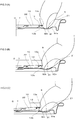
FIG. 3 ] (A) to (C) inFig. 3 are explanatory views of a tab pulling-up operation. - [
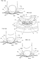
FIG. 4 ] (A) to (C) inFig. 4 are explanatory views of the pulling-up operation whenFig. 3 is viewed from a rear end of a finger hook portion of a tab, and (D) is an action explanatory view of side slopes. - [
FIG. 5] Fig. 5 illustrates can bodies for evaluation tests, wherein (A) is a view showing a state in whichclass 1 type can bodies are stacked in two tiers, and (B) is a view showing a state in whichclass 2 type can bodies are stacked in two tiers. - [
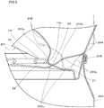
FIG. 6] Fig. 6 is an enlarged cross sectional view of main parts of stacked portions of a first can body of (A) inFig. 5 . - [
FIG. 7] Fig. 7 is an enlarged cross sectional view of main parts of stacked portions of a second can body of (B) inFig. 5 . - Hereinafter, the present invention will be described in detail based on a preferred embodiment thereof as illustrated.
-
Fig. 1 illustrates an easy open can lid according to the embodiment of the present invention. - That is, this easy open can lid is provided with a can lid
main body 1 in which ascore 6 surrounding an opening expectedportion 8 serving as a spout is formed, and atab 10 for score breaking fixedly attached to the can lidmain body 1. - The can lid
main body 1 has acircular center panel 2, achuckwall radius 3 protruding downward from a peripheral edge of thecenter panel 2, achuckwall 4 rising from an outer side wall of thechuckwall radius 3, and a seamingpanel 5 formed continuously with thechuckwall 4. Thecenter panel 2 has afirst panel surface 21 at a panel peripheral edge side and asecond panel surface 22, which is arranged at an inner side of thefirst panel surface 21 and constitutes a recessed portion that is lower by one step or level than thefirst panel surface 21, wherein thesecond panel surface 22 is divided from thefirst panel surface 21 by a steppedportion 22b, and the opening expectedportion 8 and thetab 10 are arranged on thefirst panel surface 21. - The
tab 10 is of a stay-on type, and is fixed to arivet portion 7 projecting from a panel center O (can lid center) of thecircular center panel 2. The opening expectedportion 8 is formed in one semicircular region when thecenter panel 2 is divided in half by a first center line M passing through the panel center O, and thescore 6 has a startingend portion 6a in the vicinity of therivet portion 7, and extends to aterminal end 6b so as to surround the peripheral edge of the opening expectedportion 8. The opening by thetab 10 is opened toward theterminal end 6b by initially breaking the startingend portion 6a. - The
tab 10 is a plate-like member formed in a substantially track shape, wherein one end of the tab in the major axis direction is an arc-shaped tabtip end portion 11, and the other end thereof is a linearfinger hook portion 13. Thetab 10 is arranged along a second center line N passing through the panel center O and orthogonal to the first center line M, wherein the tabtip end portion 11 goes over the panel center O, further goes over the startingend portion 6a of thescore 6 to overlap the opening expectedportion 8 side, and thefinger hook portion 13 of thetab 10 is arranged near a peripheral edge of thecenter panel 2 on the opposite side of the opening expectedportion 8 with respect to the panel center O. - The
finger hook portion 13 of thetab 10 linearly extends in a direction orthogonal to the second center line N, and the opposite end portions thereof reachside portions tab 10 viacorner portions tab 10 has anelliptical hole 14 formed therein adjacent to thefinger hook portion 13, and in this example, thefinger hook portion 13 is a narrow plate-like portion between arear end 13a thereof and thehole 14. - As illustrated in (B) of
Fig. 1 , a curledportion 17, which is formed by folding back a plate material constituting thetab 10 to a lower surface side, is formed over the entire periphery of the outer peripheral edge of thetab 10, and the curledportion 17 at therear end 13a of thefinger hook portion 13 is aflat portion 20 in which a central portion thereof in the direction orthogonal to the second center line N is flattened by a predetermined range (see (C) inFig. 1 ). - An embossed
portion 9 locally recessed in a concave shape is formed in the vicinity of therear end 13a of thefinger hook portion 13 of thecenter panel 2, and further, dimples 30, 30 acting as convex portions are arranged in bilateral symmetry with respect to the second center line N in the vicinity of the opposite sides of the embossedportion 9. The embossedportion 9 is arranged in a region of thesecond panel surface 22 and close to the steppedportion 22b between thesecond panel surface 22 and thefirst panel surface 21. Hereinafter, the embossedportion 9 and thedimples 30 will be described in detail. -
Fig. 2 (A) shows the vicinity of the embossedportion 9 in an enlarged manner, and contour lines are added to clarify the undulating state. The contour lines are drawn at predetermined height intervals with a ground contact surface of the annularchuck wall radius 3 used as a horizontal plane, for example. Specifically, a distance from thefirst panel surface 21 to thebottom surface 91 of the embossedportion 9 is 1.1 mm ± 0.4 mm, and the number of contour line intervals is 17 at 1.1 mm. - The embossed
portion 9 is formed on thesecond panel surface 22 at a predetermined depth, and is provided with aflat bottom surface 91 and an innerperipheral wall 92 surrounding thebottom surface 91. Thebottom surface 91 has a trapezoidal shape line-symmetrical with respect to the second center line N, and includes afirst side 91a at the opposite side (panel peripheral edge side) from the panel center O, asecond side 91b at the panel center O side, and a pair oflateral sides first side 91a and the opposite ends of thesecond side 91b, wherein thefirst side 91a and thelateral sides second side 91b at the panel center O side is a straight line orthogonal to the second center line N. In addition, a corner between thefirst side 91a and thelateral side 91c is rounded. - The inner
peripheral wall 92 of the embossedportion 9 is inclined in a direction expanding upward, and has afirst slope 92a positioned at the opposite side of the panel center O, asecond slope 92b at the enteral side of the can lid, and a pair ofside slopes first slope 92a and the opposite ends of thesecond slope 92b. The outline shape of the outer peripheral edge of the innerperipheral wall 92 is a fan or sector shape in which the outer peripheral edge of thefirst slope 92a is an arc of a fan and the tip of thesecond slope 92b is the center of the fan. The pair ofside slopes - The
first slope 92a and the side slopes 92c, 92c are inclined surfaces whose upper edges continue to thefirst panel surface 21, and thesecond slope 92b is an inclined surface whose upper edge continues to thesecond panel surface 22. At positions of transition from the side slopes 92c, 92c to thesecond slope 92b, the steppedportion 22b is branched from the side slopes 92c to detour thedimples 30. The steppedportion 22b has a pair of detour portions 22b1 that are each continuous with aslope region 30b at a side of eachdimple 30 facing thetab 10, thereby constituting a part of a slope of eachdimple 30. - On the other hand, a lower approximately two thirds portion of each
side slope 92c is connected to thesecond slope 92b. - The branching position of the stepped
portion 22b from thesecond slope 92b is in the vicinity of a virtual branch line L passing through a linearsecond side 91b of thebottom surface 91, and a region of the innerperipheral wall 92 at the panel center O side from the virtual branch line L is defined as thesecond slope 92b. A plurality of contour lines in thesecond slope 92b are curved lines concaved toward thebottom surface 91 when viewed from thesecond panel surface 22, and it is shown that the contour lines are recessed in a valley shape having a portion thereof along the second center line N as a valley bottom. - The
second slope 92b extends toward the panel center O at least up to a position facing the back surface of thefinger hook portion 13, and in this embodiment, the entiresecond slope 92b constitutes a guide recess for guiding a fingertip in the present invention, and in addition, the side slopes 92c also constitute a part of the guide recess. - Now, the undulating state of the
second slope 92b will be described with reference to the contour lines. - For the purpose of explanation, imaginary lines K, K passing through the opposite ends of the
second side 91b of thebottom surface 91 and parallel to the second center line N are drawn, and a region of thesecond slope 92b sandwiched by the imaginary lines K, K is defined as a central region 92b1, and the other regions of thesecond slope 92b located at the opposite sides of the central region 92b1 with respect to the imaginary lines K, K and connected to the side slopes 92c, 92c, respectively, are defined as transition regions 92b2, 92b2. - The outer edge of the
second slope 92b is a second contour line b1 viewed from thesecond panel surface 22 side, and a first contour line b0 located at the outer side of the second contour line b1 indicates a slight inclination of thesecond panel surface 22. - Assuming that the contour lines drawn toward the bottom surface, including the contour line b1, is denoted by bn, each contour line bn has a curved portion bn1, which is linearly symmetrical with respect to the second center line N and is curved in a convex arc shape toward the panel center O in the central region 92b1, and oblique line portions bn2, bn2, which extend from the opposite ends of the curved portion bn1 toward the side slopes 92c, 92c in the transition region 92b2. The oblique line portions bn2, bn2 extend line-symmetrically with respect to the second center line N, while being inclined in a direction in which the interval between them becomes narrower toward the panel center O. The oblique line portions bn2, bn2 are slightly curved outward (in the opposite direction with respect to the second center line N) in a convex manner, and are smoothly continuous with the contour lines c2, c2 in the side slopes 92c, 92c, respectively. On the other hand, connecting portions between the oblique line portions bn2, bn2 and the curved portion bn1 are also smoothly continuous, but in the contour line b1, they are smoothly connected with each other through a connecting portion b13 of an outwardly concave arc (i.e., concaved in the opposite direction with respect to the second center line N).
- In addition, the intervals between the adjacent curved portions bn1 of the individual contour lines bn in the central region 92b1 are substantially constant from the
bottom surface 91 to a predetermined height, and then increase therefrom toward thesecond panel surface 22. The intervals between the adjacent curved portions bn1 at the bottom surface side are as wide as about 2 times the intervals between the adjacent contour lines at thefirst slope 92a side. Therefore, the angle of inclination of thesecond slope 92b along the second center line N is a constant gentle angle smaller than the angle of inclination of thesecond slope 92a from thebottom surface 91 to the predetermined height, and then gradually becomes more gentle up to the second panel surface, so that thesecond slope 92b smoothly connects to thesecond panel surface 22. - The angle of inclination along the second center line N of the
second slope 92b located at therear end 13a side of thefinger hook portion 13 is preferably set to be 5° - 22° with respect to thebottom surface 91. This angle of inclination is the angle of a straight line portion of thesecond slope 92b shown in the cross section of (B) inFig. 1 from thebottom surface 91 to a position not overlapping thetab 10. - In
Fig. 2 , (B) through (D) are cross sections of thesecond slope 92b cut in a direction orthogonal to the second center line N. - (D) in
Fig. 2 is a cross section taken along thesecond side 91b of thebottom surface 91, in which the central region 92b1 is linear, and the transition regions 92b2, 92b2 are straight inclined sides. An opening width of thesecond slope 92b on thesecond panel surface 22 in this cross section, i.e., a width (a width in the direction orthogonal to the second center line N) Wd between the upper ends of the inclined sides of the transition regions 92b2, 92b2, is a maximum width of thesecond slope 92b. - (C) in
Fig. 2 is a cross sectional view cut at a position along the tops 30a of thedimples 30, in which the central region 92b1 has an arc shape slightly curved downward, with the depth thereof from thesecond panel surface 22 being shallow, and the transition regions 92b2, 92b2 are straight inclined sides. An opening width of thesecond slope 92b at the second panel surface side in this cross section, i.e., a width (a width in the direction orthogonal to the second center line N) Wc between the upper ends of the inclined sides of the transition regions 92b2, 92b2, is narrower than Wd. - (B) in
Fig. 2 is a cross sectional view taken near the tip portion of the central region 92b1. In this position, there is no transition region, and an opening width (a width in the direction orthogonal to the second center line N) Wb on thesecond panel surface 22 is further narrower than Wc. - The
dimples first panel surface 21 so as to protrude upward. When the dimples are formed on thefirst panel surface 21, it is possible to suppress the amount of decrease in sheet thickness when eachdimple 30 is formed, which is more advantageous in terms of formability or moldability than when the dimples are formed on thesecond panel surface 22. In addition, a coating film coated on the surface is not damaged by excessive stretching. - The
dimples corner portions tab 10, and are basically provided to prevent accidental opening when cans are stacked, but in this embodiment, they have a function of guiding a fingertip. - That is, an interval A between the
apexes dimples apexes apexes Fig. 2 ). The shape of thedimples - The interval A between the tops 30a, 30a of the
dimples - A detailed look at the contour lines of the
dimples dimple 30 is displaced toward the detour portion 22b1 side of the steppedportion 22b so that it is arranged close to acorner portion 13c of thetab 10. Theslope regions 30b facing thecorner portions 13c of thetab 10 are respectively located in the detour portions 22b1 of the steppedportion 22b, the detour portions 22b1 are respectively continuous with theslope regions 30b of thedimples 30 to constitute parts of the slopes of thedimples 30, and the detour portions 22b1 spreading to thesecond panel surface 22 side protrude so as to overlap the back surface side of thecorner portions 13c of thetab 10. On the other hand, theslope regions 30c of thedimples 30 facing the side slopes 92c of the embossedportion 9 are respectively inclined surfaces continuous with the side slopes 92c of the embossedportion 9. - Next, the operation of the can lid of this embodiment will be described with reference to
Figs. 3 and4 . - In an opening operation, first, a fingertip is inserted into the embossed
portion 9, so that the fingertip is hooked on therear end 13a of thefinger hook portion 13 of the tab 10 (see (A)Fig. 3 and (A) inFig. 4 ). - Here, with reference to (D) in
Fig. 4 , the operation of the side slopes 92c, 92c until the fingertip is guided from the bottom surface of the embossedportion 9 to thesecond slope 92b will be described. In the figure, the side slopes 92c, 92c and theslope regions dimples second slope 92b continuous with the side slopes 92c, 92c are hatched obliquely. In addition, a portion hatched in a vertical and horizontal grid pattern schematically indicates a region of an abutment portion S in which a fingertip portion of (A) inFig. 3 is in abutment with thebottom surface 91. - In the initial stage of pulling up, the abutment portion S moves from the
bottom surface 91 toward thesecond slope 92b, but since the side slopes 92c, 92c are inclined in a direction closer to the second center line N toward the panel center, even if the abutment portion S deviates from the second center line N toward oneside slope 92c, as shown by S1 in the figure, the abutment portion S moves toward thesecond slope 92b while correcting the deviation in a direction closer to the second center line N as shown by an arrow in the figure, so that it is directed in a direction along the second center line N, i.e., in a direction toward the panel center O, and further, even after reaching thesecond slope 92b, it is continuously guided by the transition regions 92b2, 92b2 of thesecond slope 92b continuous with the side slopes 92c, 92c. - In particular, in this embodiment, the
slope regions dimples portion 9, and hence, not only the abutment portion S of the fingertip but also the side faces of the fingertip are restricted from moving in a direction away from the second center line N by theslope regions dimples - Then, as illustrated in (B) of
Fig. 3 , thetab 10 is pulled upward. In the initial stage of pulling up, as illustrated in (B) and (C) inFig. 3 , the fingertip portion is guided from thebottom surface 91 of the embossedportion 9 along the inclined surface of the central region 92b1 of the valley-shapedsecond slope 92b to the central portion in the width direction of the back surface of thefinger hook portion 13 along the second center line N (see (B) and (C) inFig. 4 ). That is, in thesecond slope 92b, the central region 92b1 is located at a position deeper than the left and right transition regions 92b2, 92b2, and the fingertip is automatically guided to a deep position of the central region 92b1 by means of the pull-up reaction acting on the fingertip from thetab 10. - In addition, when the
second slope 92b is cut in the direction orthogonal to the second center line N, the opening width of thesecond slope 92b in thesecond panel surface 22 is wide at thebottom surface 91 side of the embossedportion 9, and gradually narrows toward the panel center O, so that the finger is naturally guided to the central portion in the width direction of the back surface of thefinger hook portion 13. - Further, the central region 92b1 serving as the valley bottom of the
second slope 92b is a gentle slope toward the panel center O along the second center line N, and hence, thetab 10 is pulled up as the fingertip is gradually lifted. - In particular, in this embodiment, since the interval A between the
dimples right dimples second slope 92b, so that the fingertip is guided to the central region 92b1 of thesecond slope 92b from a finger hooking stage without being deviated to the left and right. - In this way, in the initial stage of pulling up the
tab 6 by hooking the finger on the rear end of thefinger hook portion 13, thesecond slope 92b guides the path of the fingertip along the second center line N to the center in the width direction of the back surface of thefinger hook portion 13, and hence, in the later pulling-up operation, the direction of a pulling-up force does not obliquely deviate significantly from the direction of the panel center O, so that the pulling-up force can be concentrated on the score startingend portion 6a in the vicinity of therivet portion 7 through the tabtip end portion 11 thereby to break thescore 6. - Then, the prevention of accidental opening by the
dimples 30 as well as formability thereof in the present embodiment will be described. - The can lid of the present invention can be used in both a negative pressure can and a positive can, and is not limited to a positive pressure can, but regarding the prevention of accidental opening of positive pressure cans, which are subject to severe conditions, the height of the
dimples 30 on can lids was changed to examine catching or snagging between a leg portion of a bottom of an upper can and a tab of a can lid of a lower can when stacked in a pile, and it was found that when the height was smaller than 0.5 mm, the snagging occurred easily, whereas when the height was equal to or greater than 0.5 mm, the snagging was less likely to occur, and unintentional or accidental opening was able to be prevented. - The height h of the
dimples 30 is a height from thesecond panel 22 that is one step or level lower than thefirst panel 21, as illustrated in (B) and (C) inFig. 1 . - The higher the height of the
dimples 30 is, the more difficult it is for the tab of the lower can lid to be snagged or caught by the leg of the upper can bottom, but if the protrusion height exceeds 1.2 mm, the wall thickness of thedimples 30 becomes thin and cracks may occur. As a result of intensive studies, it was found that the height of dimples is preferably 0.5 mm or more and 1.2 mm or less from the point of view of prevention of accidental opening and formability. More preferably, it is 0.5 mm or more and 1.2 mm or less, and further preferably, it is 0.8 mm or more and 1.2 mm or less. - In order to examine the height of the dimples, an evaluation test was conducted on the accidental opening and formability. The evaluation test will be described below.
- In the evaluation test, with respect to the can lid of the above-described embodiment, four types of can lid samples in which the height of the
dimples 30 was changed were prepared, and two types of can main bodies with different leg shapes of the can bottoms were each filled with a content to be a positive pressure in a sealed state, after which the can lids were seamed and fixed thereto to produce positive pressure cans, and the unintentional openability and formability were evaluated. - First,
class 1 type canbodies 200 andclass 2 type canbodies 300 used in the evaluation test will be described with reference toFig. 5 . (A) inFig. 5 shows theclass 1 type canbodies 200, and (B) inFig. 5 shows theclass 2 type canbodies 300, in each of which the can bodies are stacked in two tiers or stages. In this figure, the can lids are denoted byreference numeral 100. - The
class 1 type canbodies 200 are each a 2-piece can, as illustrated in (A) inFig. 5 , and the can lids 100 are each seamed and fixed to the open end of eachbody portion 204 to form aseamed portion 205. Each can bottom 201 has adome portion 202 recessed in a concave shape toward the inside of a can, and an annular firstshaped leg portion 203 projecting downward from an outer peripheral edge of thedome portion 202, and when positive pressure cans are vertically stacked, the firstshaped leg portion 203 of thecan bottom 201 of an upper can is placed at a position close to thefinger hook portion 13 of thetab 10 on thecan lid 100 of a lower can. An innerperipheral surface 203a of the firstshaped leg portion 203 is an inclined surface that is inclined in a direction in which its diameter becomes smaller toward the inside of the can. In addition, an outerperipheral surface 203b of the firstshaped leg portion 203 is inclined in a direction in which its diameter gradually increases in an upward direction. - The
class 2 type canbodies 200 are each a 2-piece can, as illustrated in (B) inFig. 5 , and the can lids 100 are each seamed and fixed to the open end of eachbody portion 304 to form aseamed portion 305. Each can bottom 301 also has adome portion 302 recessed in a concave shape toward the inside of a can, and an annular secondshaped leg portion 303 projecting downward from an outer peripheral edge of thedome portion 302, as illustrated in (B) inFig. 5 , and when cans are vertically stacked, the secondshaped leg portion 303 of thecan bottom 301 of an upper can is placed at a position close to the finger hook portion of the tab on thecan lid 100 of a lower can. The secondshaped leg portion 303 is referred to as a bottom reformed shape. In thissecond can body 300, the innerperipheral surface 303a of the secondshaped leg portion 303 is an inclined surface that is inclined in a direction in which its diameter becomes larger in a direction toward a radial direction (in an expanding direction), and the secondshaped leg portion 303 of theupper can bottom 301 is more easily snagged or caught, when stacked, by the tab of thecan lid 100 of the lower can body than in the case of theclass 1 type canbody 200. - Next, a snagging state in which a first
shaped leg portion 203 and atab 10 of theclass 1 type canbodies 200 are caught with each other will be described with reference toFig. 6 . -
Fig. 6 is an enlarged cross sectional view of main parts of stacked portions of the first canbodies 200 in (A) ofFig. 5 , in which the firstshaped leg portion 203 in a normally stacked state is indicated by an alternate long and two short dashes line, and the firstshaped leg portion 203 in an inclined state is indicated by a solid line. The cross section is taken at acorner 13c of thetab 10. - In the normally stacked state, as shown by the alternate long and two short dashes line, a
lower end 203c of an arc shape in cross section of the firstshaped leg portion 203 is in contact with the first panel surface of thecan lid 100 of the lower can, and the outerperipheral surface 203b of the firstshaped leg portion 203 is in contact with an upper end of theseamed portion 205 of the lower can. - In this state, when the upper can is tilted, as shown by the solid line, the outer
peripheral surface 203b of the firstshaped leg portion 203 rides on theseamed portion 205, and thelower end portion 203c of the arc shape in cross section rides on thedimple 30 and comes into contact with acorner portion 13c of thefinger hook portion 13. Further tilted from this state, theleg portion 203 is caused to move in a direction to snag or lift thetab 10 upwardly, and if such a snag is strong, an unintentional or accidental opening will occur due to the action of leverage. - Further, a snagging state in which a first
shaped leg portion 303 and atab 10 of theclass 2 type canbodies 300 are caught with each other will be described with reference toFig. 7 . -
Fig. 7 is an enlarged view of main parts of stacked portions of the second canbodies 300 in (B) ofFig. 5 , in which the firstshaped leg portion 303 in a normally stacked state is indicated by an alternate long and two short dashes line, and the secondshaped leg portion 303 in an inclined state is indicated by a solid line. The cross section is taken at acorner 13c of thetab 10. - In the normally stacked state, as shown by the alternate long and two short dashes line, a
lower end 303c of an arc shape in cross section of the secondshaped leg portion 303 is in contact with the first panel surface of thecan lid 100 of the lower can, and the outerperipheral surface 303b of the secondshaped leg portion 303 is in contact with an upper end of theseamed portion 305 of the lower can lid. - In this state, when the upper can is tilted, as shown by the solid line, the outer
peripheral surface 303b of the secondshaped leg portion 303 rides on theseamed portion 305, and thelower end portion 303c of the arc shape in cross section rides on thedimple 30 and comes into contact with acorner portion 13c of thefinger hook portion 13. Further tilted from this state, the secondshaped leg portion 303 is caused to move in a direction to snag or lift thetab 10 upwardly, and if such a snag is strong, an unintentional or accidental opening will occur due to the action of leverage. The innerperipheral surface 303a of the secondshaped leg portion 303 is inclined in a direction in which its diameter increases toward the inside (upward) of the can, so it is easily snagged or caught by a corner portion of thefinger hook portion 13 to the extent of such an inclination. - The heights of the
dimples 30 of the four types of can lids described above were of four kinds: 0.7 mm, 0.8 mm, 1.0 mm, and 1.2 mm. - The diameter of each can
lid 100 was 57.15 mm, the thickness thereof was 0.235 mm, and the internal pressure was set to 200 kPa at room temperature for both the first canbodies 200 and the second canbodies 300. - Each can
lid 100 was expanded outwardly by the internal pressure, eachtab 10 was lifted up from thesecond panel surface 22, and a clearance of each tab from the liftedsecond panel surface 22 is about 2.3 mm. - In a test, the can bodies (positive pressure) to be evaluated, which were filled with contents, were stacked in two upper and lower tiers, as illustrated in
Fig. 5 , and the first canbodies 200 and the second canbodies 300 were relatively evaluated for the presence or absence of snagging when they were tilted by hand in the direction in which the leg portion of the can bottom was caught or snagged by the tab, and the evaluation results were rated in three levels of ⊚, ○ and Δ. The evaluation levels were as follows. - ⊚: There was no snagging between the leg portion of the can bottom and the tab, and there was no occurrence of accidental opening.
- ○: Snagging between the leg portion of the can bottom and the tab was very slightly felt, but no accidental opening occurred.
- Δ: Slight snagging of the tab on the bottom of the can was slightly felt, but no accidental opening occurred.
- From the cross sectional shapes of the
dimples 30, the presence or absence of partial reduction in sheet thickness thereof was checked, and the formability of thedimples 30 were relatively evaluated. - ⊚: Very slight partial reduction in sheet thickness of the
dimples 30, but still suitable for practical use - Δ: Slight partial reduction in sheet thickness of the
dimples 30, but still suitable for practical use - As illustrated in Table 1, all of the samples of the can bottom in the
class 1 type can bodies were "⊚", and there was no snagging at all without occurrence of accidental opening. - In the samples of the can bottom in the
type 2 can bodies, "Δ" was given in 0.7 mm, "o" was given in 0.8 mm, and "⊚" was given in 1.0 mm and 1.2 mm, and there was neither snagging nor accidental opening. - It is considered that there is slight abutment in 0.7 mm, but accidental opening can be prevented in case of about 0.5 mm.
- As shown in Table 1, formability was evaluated as "⊚" in all of 0.7 mm, 0.8 mm and 1.0 mm, and the reduction in sheet thickness was very slight, and hence, there was no problem in practical use, and it is suitable for practical use. In addition, in 1.2 mm, the reduction in the sheet thickness was slight, and it was evaluated to be suitable for practical use.
- Here, note that in the above-mentioned embodiment, the slope at the rear end side of the finger hook portion of the embossed portion is configured to include the guide recess for guiding a fingertip that extends toward the center of the can lid at least up to a position facing the central portion in the width direction of the back surface of the finger hook portion, but only the dimples may be provided, while omitting the guide recess.
- The movable range of a finger in the short side direction of the tab is limited by the pair of the dimples, so that a fingertip is guided to the central portion in the width direction of the finger hook portion, thereby making it easy to direct the pulling-up direction of the tab toward the central direction of the lid.
Table 1 Hight of dimples (convex portions) 30 [mm] Presence or absence of snagging of first shaped leg portion 203 andtab 10Presence or absence of snagging of second shaped leg portion 303 andtab 10Presence or absence of reduction in partial sheet thickness of dimples 300.7 ⊚ Δ ⊚ 0.8 ⊚ ○ ⊚ 1.0 ⊚ ⊚ ⊚ 1.2 ⊚ ⊚ Δ - Here, note that in the above-mentioned embodiment, the
finger hook portion 13 is formed in a linear shape, but a step-shaped or arch-shaped tip-up portion may be provided in the central portion in the width direction of thefinger hook portion 13. In addition, in the above embodiment, thehole 14 is provided in thetab 10, but thehole 14 may be omitted. - In addition, the
center panel 2 is configured to include thefirst panel surface 21 and thesecond panel surface 22, which is lower than the first panel surface, but thesecond panel surface 22 may be omitted. Moreover, therivet portion 7 is provided in the panel center of the center panel, but therivet portion 7 does not need to be located at the panel center position, and therivet portion 7 may be shifted from the panel center on the second center line. -
- 1
- can lid body
- 2
- center panel
21 first panel surface, 22 second panel surface
22b stepped portion, 22b1 detour portions - 3
- chuck wall radius, 4 chuck wall, 5 seaming panel
- 6
- score, 6a score starting end portion, 6b score terminal end portion
- 7
- rivet portion, 8 opening expected portion
- 9
- embossed portion
91 bottom surface, 91a first side, 91b second side, 91c lateral sides,
92 inner peripheral wall, 92a first slope, 92b second slope
92b1 central region, 92b2 transition regions
92c side slopes - 10
- tab
11 tab tip end portion - 13
- finger hook portion
13a rear end, 13b back surface, 13c corner portions, 14 hole
16 side portions, 17 curled portion
20 flat portion (central portion in the width direction of the back surface of the finger hook portion) - 30
- dimples, 30a top, 30b, 30c slope regions
- A
- interval between dimples
- M
- first center line, N second center line
- O
- panel center (lid center)
- Wb, Wc, Wd
- widths of second slope
Claims (13)
- A can lid in which a tab for score breaking is fixed to a can lid main body, and an embossed portion, into which a fingertip is insertable, is provided in the vicinity of a rear end of a finger hook portion of the tab,
characterized in that a slope of the embossed portion at a rear end side of the finger hook portion is provided with a guide recess for guiding a fingertip that extends toward a center of the can lid at least up to a position facing a central portion in a width direction of a back surface of the finger hook portion. - The can lid according to claim 1, wherein when assuming a center line that passes through the center of the can lid and a center of the finger hook portion, a width of the guide recess in a direction orthogonal to the center line is gradually narrowed toward a central direction of the can lid.
- The can lid according to claim 1 or 2, wherein a bottom portion of the guide recess comprises an inclined surface that gradually becomes shallower from a bottom surface of the embossed portion toward the center of the can lid, and the inclined surface has an angle of inclination smaller than that of a slope of the embossed portion at a side opposite to the center of the can lid.
- The can lid according to any one of claims 1 to 3, wherein the embossed portion has a bottom surface and an inner peripheral wall surrounding the bottom surface; the inner peripheral wall has a first slope at a side opposite to the center of a can lid, a second slope at a central side of the can lid, and a pair of side slopes connecting to opposite ends of the first slope; and the pair of side slopes are inclined in a direction gradually approaching toward the can lid center side, and constitute a part of the guide recess.
- The can lid according to any one of claims 1 to 4, wherein the can lid main body is provided with convex portions in the vicinity of a rear end of the finger hook portion of the tab at opposite sides of the embossed portion that is sandwiched therebetween.
- The can lid according to claim 4, wherein
the can lid main body is provided with convex portions in the vicinity of a rear end of the finger hook portion of the tab at opposite sides of the embossed portion that is sandwiched therebetween; and
the convex portions have slopes at the side of the embossed portion, the slopes comprising inclined surfaces continuous with the side slopes of the embossed portion. - The can lid according to claim 5 or 6, wherein each of the convex portions has a height in a range of 0.5 mm or more and 1.2 mm or less.
- The can lid according to any one of claims 5 to 7, wherein a distance between apexes of the convex portions is in a range of 13 mm ± 2 mm.
- The can lid according to any one of claims 5 to 8, wherein
the can lid main body has a circular center panel, which has a first panel surface at an outer peripheral edge side thereof and a second panel surface at an inner side of the first panel surface, the second panel surface being lower by one step than an inner peripheral edge of the first panel surface via a stepped portion; and the convex portions are provided on the first panel surface. - The can lid according to claim 9, wherein the embossed portion has a bottom surface and an inner peripheral wall surrounding the bottom surface; the inner peripheral wall has a first slope at a side opposite to the center of the can lid, a second slope at a central side of the can lid, and side slopes connecting to opposite ends of the first slope; the first slope and the side slopes have upper ends continuing to the first panel surface; and the second slope has an upper end continuing to the second panel surface.
- A can lid in which a tab for score breaking is fixed to a can lid main body, and an embossed portion, into which a fingertip is insertable, is provided in the vicinity of a rear end of a finger hook portion of the tab,
characterized in that the can lid main body is provided with convex portions in the vicinity of the rear end of the finger hook portion of the tab at opposite sides of the embossed portion that is sandwiched therebetween; and
a height of each of the convex portions is set in a range of 0.5 mm - 1.2 mm. - The can lid according to claim 11, wherein a distance between apexes of the convex portions is in a range of 13 mm ± 2 mm.
- The can lid according to claim 11 or 12, wherein
the can lid main body has a circular center panel, which has a first panel surface at an outer peripheral edge side thereof and a second panel surface at an inner side of the first panel surface, the second panel surface being lower by one step than an inner peripheral edge of the first panel surface via a stepped portion; and
the convex portions are provided on the first panel surface.
Applications Claiming Priority (2)
| Application Number | Priority Date | Filing Date | Title |
|---|---|---|---|
| JP2018071631 | 2018-04-03 | ||
| PCT/JP2019/014849 WO2019194237A1 (en) | 2018-04-03 | 2019-04-03 | Can lid |
Publications (2)
| Publication Number | Publication Date |
|---|---|
| EP3778414A1 true EP3778414A1 (en) | 2021-02-17 |
| EP3778414A4 EP3778414A4 (en) | 2022-01-12 |
Family
ID=
Also Published As
| Publication number | Publication date |
|---|---|
| US20210155371A1 (en) | 2021-05-27 |
| JPWO2019194237A1 (en) | 2021-04-08 |
| KR102516439B1 (en) | 2023-03-30 |
| JP7472785B2 (en) | 2024-04-23 |
| CN112074463B (en) | 2022-09-23 |
| KR20200127249A (en) | 2020-11-10 |
| US11560255B2 (en) | 2023-01-24 |
| WO2019194237A1 (en) | 2019-10-10 |
| CN112074463A (en) | 2020-12-11 |
Similar Documents
| Publication | Publication Date | Title |
|---|---|---|
| US11560255B2 (en) | Can lid | |
| IL182173A (en) | Sheet metal lid for a beverage can provided with a large perforation | |
| US20100126994A1 (en) | Tab for a closure and process for making such tab | |
| JP2799795B2 (en) | Easy opening can lid | |
| EP2858911B1 (en) | Easy open closure with improved pressure performance | |
| JP4879802B2 (en) | Can lid and can lid manufacturing method | |
| CZ95698A3 (en) | Tank body with two arms | |
| JP7590782B2 (en) | Plastic containers | |
| JP4588398B2 (en) | Can lid | |
| CN105339278B (en) | Cover and beverage can | |
| JP2000128168A (en) | Full open can lid | |
| JP2004161360A (en) | Easy opening can lid | |
| JP5246858B2 (en) | Easy-to-open can lid | |
| KR102706400B1 (en) | Electrode for secondary battery and method of manufacturing electrode | |
| JP5475556B2 (en) | Method for manufacturing can lid and tab | |
| JP5588259B2 (en) | Can lid | |
| JP2020142849A (en) | Tabs and can lids for opening can lids | |
| JP2012035852A (en) | Can lid | |
| KR102552575B1 (en) | Container for cooking | |
| JP5542257B2 (en) | Container lid | |
| JP3624835B2 (en) | can | |
| JP5658940B2 (en) | Can lid | |
| RU2811781C2 (en) | Easy to open end cover with increased panel rigidity | |
| JP2024052247A (en) | Can Lids | |
| JPH0910874A (en) | Simple opening can lid |
Legal Events
| Date | Code | Title | Description |
|---|---|---|---|
| STAA | Information on the status of an ep patent application or granted ep patent |
Free format text: STATUS: THE INTERNATIONAL PUBLICATION HAS BEEN MADE |
|
| PUAI | Public reference made under article 153(3) epc to a published international application that has entered the european phase |
Free format text: ORIGINAL CODE: 0009012 |
|
| STAA | Information on the status of an ep patent application or granted ep patent |
Free format text: STATUS: REQUEST FOR EXAMINATION WAS MADE |
|
| 17P | Request for examination filed |
Effective date: 20201006 |
|
| AK | Designated contracting states |
Kind code of ref document: A1 Designated state(s): AL AT BE BG CH CY CZ DE DK EE ES FI FR GB GR HR HU IE IS IT LI LT LU LV MC MK MT NL NO PL PT RO RS SE SI SK SM TR |
|
| AX | Request for extension of the european patent |
Extension state: BA ME |
|
| DAV | Request for validation of the european patent (deleted) | ||
| DAX | Request for extension of the european patent (deleted) | ||
| A4 | Supplementary search report drawn up and despatched |
Effective date: 20211210 |
|
| RIC1 | Information provided on ipc code assigned before grant |
Ipc: B65D 17/32 20060101AFI20211206BHEP |
|
| STAA | Information on the status of an ep patent application or granted ep patent |
Free format text: STATUS: EXAMINATION IS IN PROGRESS |
|
| 17Q | First examination report despatched |
Effective date: 20240305 |
|
| GRAP | Despatch of communication of intention to grant a patent |
Free format text: ORIGINAL CODE: EPIDOSNIGR1 |
|
| STAA | Information on the status of an ep patent application or granted ep patent |
Free format text: STATUS: GRANT OF PATENT IS INTENDED |
|
| INTG | Intention to grant announced |
Effective date: 20240930 |
|
| STAA | Information on the status of an ep patent application or granted ep patent |
Free format text: STATUS: THE APPLICATION IS DEEMED TO BE WITHDRAWN |
|
| 18D | Application deemed to be withdrawn |
Effective date: 20250131 |