EP3778400A1 - Aircraft air conditioning pack assembly and method of assembling - Google Patents
Aircraft air conditioning pack assembly and method of assembling Download PDFInfo
- Publication number
- EP3778400A1 EP3778400A1 EP20184023.8A EP20184023A EP3778400A1 EP 3778400 A1 EP3778400 A1 EP 3778400A1 EP 20184023 A EP20184023 A EP 20184023A EP 3778400 A1 EP3778400 A1 EP 3778400A1
- Authority
- EP
- European Patent Office
- Prior art keywords
- air conditioning
- conditioning pack
- aircraft
- pack
- exterior panel
- Prior art date
- Legal status (The legal status is an assumption and is not a legal conclusion. Google has not performed a legal analysis and makes no representation as to the accuracy of the status listed.)
- Granted
Links
Images



Classifications
-
- B—PERFORMING OPERATIONS; TRANSPORTING
- B64—AIRCRAFT; AVIATION; COSMONAUTICS
- B64D—EQUIPMENT FOR FITTING IN OR TO AIRCRAFT; FLIGHT SUITS; PARACHUTES; ARRANGEMENT OR MOUNTING OF POWER PLANTS OR PROPULSION TRANSMISSIONS IN AIRCRAFT
- B64D13/00—Arrangements or adaptations of air-treatment apparatus for aircraft crew or passengers, or freight space
- B64D13/06—Arrangements or adaptations of air-treatment apparatus for aircraft crew or passengers, or freight space the air being conditioned
- B64D13/08—Arrangements or adaptations of air-treatment apparatus for aircraft crew or passengers, or freight space the air being conditioned the air being heated or cooled
-
- B—PERFORMING OPERATIONS; TRANSPORTING
- B64—AIRCRAFT; AVIATION; COSMONAUTICS
- B64D—EQUIPMENT FOR FITTING IN OR TO AIRCRAFT; FLIGHT SUITS; PARACHUTES; ARRANGEMENT OR MOUNTING OF POWER PLANTS OR PROPULSION TRANSMISSIONS IN AIRCRAFT
- B64D13/00—Arrangements or adaptations of air-treatment apparatus for aircraft crew or passengers, or freight space
- B64D13/06—Arrangements or adaptations of air-treatment apparatus for aircraft crew or passengers, or freight space the air being conditioned
-
- B—PERFORMING OPERATIONS; TRANSPORTING
- B64—AIRCRAFT; AVIATION; COSMONAUTICS
- B64F—GROUND OR AIRCRAFT-CARRIER-DECK INSTALLATIONS SPECIALLY ADAPTED FOR USE IN CONNECTION WITH AIRCRAFT; DESIGNING, MANUFACTURING, ASSEMBLING, CLEANING, MAINTAINING OR REPAIRING AIRCRAFT, NOT OTHERWISE PROVIDED FOR; HANDLING, TRANSPORTING, TESTING OR INSPECTING AIRCRAFT COMPONENTS, NOT OTHERWISE PROVIDED FOR
- B64F5/00—Designing, manufacturing, assembling, cleaning, maintaining or repairing aircraft, not otherwise provided for; Handling, transporting, testing or inspecting aircraft components, not otherwise provided for
- B64F5/10—Manufacturing or assembling aircraft, e.g. jigs therefor
-
- B—PERFORMING OPERATIONS; TRANSPORTING
- B64—AIRCRAFT; AVIATION; COSMONAUTICS
- B64D—EQUIPMENT FOR FITTING IN OR TO AIRCRAFT; FLIGHT SUITS; PARACHUTES; ARRANGEMENT OR MOUNTING OF POWER PLANTS OR PROPULSION TRANSMISSIONS IN AIRCRAFT
- B64D13/00—Arrangements or adaptations of air-treatment apparatus for aircraft crew or passengers, or freight space
- B64D13/06—Arrangements or adaptations of air-treatment apparatus for aircraft crew or passengers, or freight space the air being conditioned
- B64D2013/0603—Environmental Control Systems
-
- B—PERFORMING OPERATIONS; TRANSPORTING
- B64—AIRCRAFT; AVIATION; COSMONAUTICS
- B64D—EQUIPMENT FOR FITTING IN OR TO AIRCRAFT; FLIGHT SUITS; PARACHUTES; ARRANGEMENT OR MOUNTING OF POWER PLANTS OR PROPULSION TRANSMISSIONS IN AIRCRAFT
- B64D13/00—Arrangements or adaptations of air-treatment apparatus for aircraft crew or passengers, or freight space
- B64D13/06—Arrangements or adaptations of air-treatment apparatus for aircraft crew or passengers, or freight space the air being conditioned
- B64D2013/0603—Environmental Control Systems
- B64D2013/0622—Environmental Control Systems used in combination with boundary layer control systems
-
- Y—GENERAL TAGGING OF NEW TECHNOLOGICAL DEVELOPMENTS; GENERAL TAGGING OF CROSS-SECTIONAL TECHNOLOGIES SPANNING OVER SEVERAL SECTIONS OF THE IPC; TECHNICAL SUBJECTS COVERED BY FORMER USPC CROSS-REFERENCE ART COLLECTIONS [XRACs] AND DIGESTS
- Y02—TECHNOLOGIES OR APPLICATIONS FOR MITIGATION OR ADAPTATION AGAINST CLIMATE CHANGE
- Y02T—CLIMATE CHANGE MITIGATION TECHNOLOGIES RELATED TO TRANSPORTATION
- Y02T50/00—Aeronautics or air transport
- Y02T50/40—Weight reduction
-
- Y—GENERAL TAGGING OF NEW TECHNOLOGICAL DEVELOPMENTS; GENERAL TAGGING OF CROSS-SECTIONAL TECHNOLOGIES SPANNING OVER SEVERAL SECTIONS OF THE IPC; TECHNICAL SUBJECTS COVERED BY FORMER USPC CROSS-REFERENCE ART COLLECTIONS [XRACs] AND DIGESTS
- Y02—TECHNOLOGIES OR APPLICATIONS FOR MITIGATION OR ADAPTATION AGAINST CLIMATE CHANGE
- Y02T—CLIMATE CHANGE MITIGATION TECHNOLOGIES RELATED TO TRANSPORTATION
- Y02T50/00—Aeronautics or air transport
- Y02T50/50—On board measures aiming to increase energy efficiency
Definitions
- the field relates generally to aircraft environmental control systems and, more specifically, to an air conditioning pack and pack bay assembly with improved heat dissipation capabilities.
- At least some known aircraft include a ram air system that provides ram air to at least one air conditioning pack of an aircraft environmental control system (ECS).
- ECS aircraft environmental control system
- the air conditioning pack is positioned within a pack bay of the aircraft along with other aircraft components.
- the air conditioning pack uses ram air to provide cooling to the high-temperature pneumatic air that is delivered to a passenger cabin of the aircraft.
- the ram air does not extract all of the internal heat load and, as a result, the heat may be transferred to the components within the pack bay and to the surrounding aircraft structure.
- At least some aircraft include a layer of insulation around the air conditioning packs to reduce the discharge of heat from the air conditioning packs to within the pack bay. However, such insulation increases the overall weight and spatial envelope of the aircraft, and may have a limited service life.
- the assembly includes an air conditioning pack configured to discharge heat, and an exterior panel positioned in close proximity to the air conditioning pack.
- the exterior panel includes an opening defined therein, a first side facing towards the air conditioning pack, and a second side defining an exterior aircraft surface configured to be in communication with a free stream airflow. At least a portion of the air conditioning pack is disposed within the opening to facilitate transferring heat from the air conditioning pack to the free stream airflow.
- the aircraft includes a pack bay defined on an underside of the aircraft, with the pack bay including an interior.
- An air conditioning pack is positioned within the interior, and the air conditioning pack is configured to discharge heat.
- An exterior panel is positioned in close proximity to the air conditioning pack and at least partially defining the interior.
- the exterior panel includes an opening defined therein, a first side facing towards the air conditioning pack, and a second side defining an exterior surface of the aircraft configured to be in communication with a free stream airflow. At least a portion of the air conditioning pack is disposed within the opening to facilitate transferring heat from the air conditioning pack to the free stream airflow.
- the method includes defining a pack bay on an underside of the aircraft, wherein the pack bay includes an interior, positioning an air conditioning pack within the interior, wherein the air conditioning pack is configured to discharge heat, and positioning an exterior panel in close proximity to the air conditioning pack to at least partially define the interior.
- the exterior panel includes an opening defined therein, and the exterior panel is positioned such that a first side thereof faces towards the air conditioning pack, and such that a second side thereof defines an exterior surface of the aircraft configured to be in communication with a free stream airflow.
- the method also includes disposing at least a portion of the air conditioning pack within the opening to facilitate transferring heat from the air conditioning pack to the free stream airflow.
- the assembly includes an air conditioning pack configured to discharge heat, and an exterior panel positioned in close proximity to the air conditioning pack.
- the exterior panel has an opening defined therein, which provides a flow communication path between the pack bay and an ambient environment. At least a portion of the air conditioning pack is disposed within the opening such that the air conditioning pack is exposed to the ambient environment. The portion of the air conditioning pack disposed within the opening has no intervening layer of thermally insulating material positioned between the air conditioning pack and the exterior panel.
- the air conditioning pack has a bottom wall that extends through the opening to be in direct flow communication with the ambient environment.
- the bottom wall may have an airfoil cross-sectional shape to facilitate preserving the aerodynamic efficiency of the aircraft.
- the heat generated by the air conditioning pack is dischargeable to the ambient environment in an efficient, space-saving, and weight-reducing manner that enhances heat rejection from the internal flow.
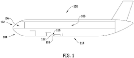
- FIG. 1 is a schematic view of an example aircraft 100.
- Aircraft 100 includes pressurized areas 102 and unpressurized areas 104.
- Pressurized areas 102 include, but are not limited to, a cockpit 106, and a passenger cabin 108.
- Unpressurized areas 104 include, but are not limited to, a pack bay 112 defined on an underside 114 of aircraft 100.
- Pack bay 112 has an interior 116, and an air conditioning pack 118 is positioned within interior 116.
- air conditioning pack 118 receives airflow from the engines, an auxiliary power unit, or electrically driven compressors (all not shown) on aircraft 100, for example.
- Air conditioning pack 118 then cools the airflow, and discharges the cooled airflow for distribution within pressurized areas 102.
- air conditioning pack 118 generates and dissipates heat during operation thereof.
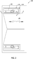
- FIG. 2 is a bottom view of a portion of aircraft 100
- FIG. 3 is a sectional view of a portion of aircraft 100 taken along line 3-3.
- Aircraft 100 includes an exterior panel 120 in close proximity to air conditioning pack 118 positioned within pack bay 112. Exterior panel 120 has an opening 122 defined therein. Exterior panel 120 also has a first side 124 that faces towards air conditioning pack 118, and a second side 126 that defines an exterior surface 128 of aircraft 100. First side 124 faces towards air conditioning pack 118 in that at least a portion of air conditioning pack 118 extends in the direction in which first side 124 faces. Exterior surface 128 is in communication with a free stream airflow 130 that is channeled past exterior panel 120.
- Free stream airflow 130 is defined by an ambient environment 132 defined exterior of aircraft 100.
- the velocity and cooling capacity of free stream airflow 130 is (generally) directly proportional to the velocity of aircraft 100, and free stream airflow 130 is channeled past exterior panel 120 in a rearward direction (RWD) or substantially rearward direction when aircraft 100 is in motion.
- RWD rearward direction
- the term "close proximity" refers to when exterior panel 120 is either in contact with, or is minimally spaced apart from, any portion of air conditioning pack 118.
- Air conditioning pack 118 includes a heat exchanger 134 defining an enclosure 134, and a plurality of ducts 135 are in flow communication with heat exchanger 134. Airflows are channeled to heat exchanger 134 via one or more ducts 135 to facilitate transferring heat between the airflows, and an airflow is discharged from heat exchanger 134 for distribution within pressurized areas 102 (shown in FIG. 1 ), for example.
- Heat exchanger 134 has a top side 136, a bottom side 138, and a plurality of lateral sides 140 extending therebetween.
- air conditioning pack 118 generates heat during operation thereof. For example, as illustrated in FIG. 3 , heat 142 is discharged from each side 136, 138, and 140 of air conditioning pack 118.
- At least a portion of air conditioning pack 118 is disposed within opening 122 of exterior panel 120 to facilitate transferring heat 142 from air conditioning pack 118 to free stream airflow 130.
- bottom side 138 of heat exchanger 134 and at least a portion of ducts 135 are disposed within opening 122, and are directly exposed to ambient environment 132.
- air conditioning pack 118 and ducts 135 are positioned to discharge heat 142 directly to free stream airflow 130.
- bottom side 138 and the portion of ducts 135 are disposed to be flush or substantially flush with exterior surface 128 of aircraft 100. As such, bottom side 138 and the portion of ducts 135 are exposed to ambient environment 132 while still maintaining or substantially maintaining the aerodynamic efficiency of aircraft 100.
- a layer 144 of thermally insulative material extends over at least a portion of heat exchanger 134.
- bottom side 138 of heat exchanger 134 is directly exposed to ambient environment 132 to facilitate heat discharge to free stream airflow 130.
- the remaining sides of heat exchanger 134 such as top side 136 and lateral sides 140, are covered by layer 144 to facilitate reducing heat transfer between air conditioning pack 118 and interior 116 of pack bay 112.
- thermally insulative material include, but are not limited to, a fiberglass material, such as in blanket form, or a closed cell foam material such as polyvinylidene fluoride or polyvinylidene difluoride (PVDF).
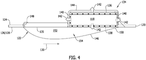
- air conditioning pack 118 includes a bottom wall 146 disposed on bottom side 138 of heat exchanger 134. At least a portion of bottom wall 146 extends through opening 122 in exterior panel 120 for positioning exterior of pack bay 112. That is, in some examples, bottom wall 146 is coupled to first side 124 of exterior panel 120 and the portion of bottom wall 146 extends from first side 124 through opening 122. Alternatively, bottom wall 146 is formed separately from heat exchanger 134 and coupled to second side 126 of exterior panel 120. In these and other examples, bottom wall 146 is oriented to be in flow communication with free stream airflow 130 to facilitate defining a thermal communication pathway for heat 142 discharged from air conditioning pack 118.
- opening 122 is at least partially defined by a forward edge 148 and a rearward edge 150 of exterior panel 120.
- bottom wall 146 extends between forward edge 148 and rearward edge 150 to facilitate sealing interior 116 from ambient environment 132.
- bottom wall 146 In addition, exposing bottom wall 146 to free stream airflow 130 facilitates reducing the aerodynamic efficiency of aircraft 100 (shown in FIG. 1 ). As such, the portion of bottom wall 146 extending through opening 122 has an airfoil cross-sectional shape to reduce the amount of drag induced to aircraft 100 by bottom wall 146 during flight.
- the shape of bottom wall 146 facilitates defining an open space 152 between heat exchanger 134 and bottom wall 146, and between ducts 135 and bottom wall 146.
- open space 152 contains air, which receives heat 142 from heat exchanger 134, and facilitates its passage through bottom wall 146, for transfer to free stream airflow 130.
- thermally conductive material 154 is positioned between air conditioning pack 118 and bottom wall 146, and between ducts 135 and bottom wall 146.
- Thermally conductive material 154 facilitates enhancing heat transfer from air conditioning pack 118 and ducts 135 to free stream airflow 130.
- Example thermally conductive materials include, but are not limited to, a thermally conductive foam material, heat pipes, or a non-structural and lightweight metallic material such as aluminum.
- FIG. 5 is a schematic sectional view of a portion of the aircraft 100 including an example sealing system 156 in which exterior panel 120 provides a primary load path for the installation of air conditioning pack 118.
- Sealing system 156 is configured to restrict the inflow of free stream airflow 130 and debris (not shown) through opening 122.
- exterior panel 120 includes an indent 158
- air conditioning pack 118 includes a flange 160 sized to be received within indent 158.
- indent 158 and flange 160 are sized such that an exterior surface 162 of air conditioning pack 118 is flush or substantially flush with exterior surface 128 of exterior panel 120 at an interface 164 defined therebetween.
- Sealing system 156 includes at least one seal member positioned about the periphery of opening 122.
- sealing system 156 includes a first seal member 166 and a second seal member 168 positioned between air conditioning pack 118 and exterior panel 120.
- Exterior panel 120 includes a side edge 170 that is spaced from lateral side 140 of air conditioning pack 118 such that a cavity 172 is defined therebetween.
- First seal member 166 is positioned within cavity 172, and is pre-loaded before being positioned within cavity 172 to facilitate sealing interior 116 of pack bay 112 from ambient environment 132.
- Second seal member 168 is coupled to air conditioning pack 118 and exterior panel 120 to facilitate sealing cavity 172.
- second seal member 168 is coupled to lateral side 140 of air conditioning pack 118, and extends across cavity 172 to further couple to first side 124 of exterior panel 120.
- a fastener 174 extends through second seal member 168, exterior panel 120, and flange 160 of air conditioning pack 118 to facilitate installing air conditioning pack 118 on aircraft 100.
- second seal member 168 statically affixed between air conditioning pack 118 and exterior panel 120 to facilitate enhancing the seal provided between interior 116 of pack bay 112 and ambient environment 132.
- a second fastener is insertable, and is accessible for removal and installation, from the exterior side of aircraft 100. As such, pack bay 112 is accessible from exterior of aircraft 100 when air conditioning pack 118 is uncoupled from exterior panel 120.
- First seal member 166 and second seal member 168 are fabricated from any material that enables aircraft 100 to function as described herein.
- An example seal material includes, but is not limited to, an elastomeric material. When fabricated from elastomeric material, first seal member 166 and second seal member 168 are capable of accommodating relative movement between air conditioning pack 118 and exterior panel 120.
- FIG. 6 illustrates the schematic sectional view shown in FIG. 5 and including an additional sealing system 176.
- Aircraft 100 includes a lower panel 178, and an attachment mechanism 180 coupled between air conditioning pack 118 and lower panel 178. Attachment mechanism 180 provides the primary load path for installing air conditioning pack 118 on aircraft 100, thereby reducing a load induced on exterior panel 120 by air conditioning pack 118 when attachment is made therebetween. As such, air conditioning pack 118 is held stationary or substantially stationary relative to lower panel 178.
- Air conditioning pack 118 is spaced from exterior panel 120 such that a gap 182 is defined between flange 160 of air conditioning pack 118 and side edge 170 of exterior panel 120.
- First seal member 166 is positioned within gap 182, and a second seal member 184 and a third seal member 186 are positioned on opposing sides of gap 182.
- Second seal member 184 is adapted to seal gap 182 and to also accommodate movement of exterior panel 120 relative to air conditioning pack 118.
- a layer 188 of a low friction coating material is applied to flange 160, and second seal member 184 has a sacrificial layer 190 of material formed thereon.
- exterior panel 120 is translatable relative to air conditioning pack 118 as a result of the sliding interface between layer 188 of low friction coating material and sacrificial layer 190.
- sealing system 176 is capable of accommodating a greater degree of relative motion between air conditioning pack 118 and exterior panel 120.
- FIG. 7 illustrates the schematic sectional view shown in FIG. 5 and including an additional sealing system 192 in which exterior panel 120 provides a primary load path for the installation of air conditioning pack 118.
- Air conditioning pack 118 is spaced from exterior panel 120 such that a gap 182 is defined between flange 160 of air conditioning pack 118 and side edge 170 of exterior panel 120.
- flange 160 includes a lip member 194 oriented to extend into interior 116 of pack bay 112.
- Sealing system 192 includes a seal member 196 positioned within gap 182, and having a first portion 198 and a second portion 200 positioned on opposing sides of gap 182. Second portion 200 of seal member 196 is coupled to, and encloses at least a portion of lip member 194. As such, lip member 194 facilitates retaining seal member 196 in place relative to air conditioning pack 118 and exterior panel 120.
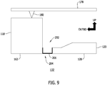
- FIG. 8 illustrates the schematic sectional view shown in FIG. 5 and including an additional sealing system 202 in a first operational mode
- FIG. 9 illustrates additional sealing system 202 in a second operational mode
- Air conditioning pack 118 and exterior panel 120 are spaced from each other such that a gap 204 is defined therebetween.
- Sealing system 202 includes a spring-seal member 206 positioned within gap 204.
- Spring-seal member 206 is pre-loaded within gap 204 when in the first operational mode to enable spring-seal member 206 to accommodate relative movement between air conditioning pack 118 and exterior panel 120.
- spring-seal member 206 is expandable to accommodate an increase in the size of gap 204 as exterior panel 120 moves away from air conditioning pack 118.
- Spring-seal member 206 may be fabricated from any material that enables sealing system 202 to function as described herein.
- An example material includes, but is not limited to, a shape memory alloy material.
- spring-seal member 206 is biasing device at least partially encapsulated by elastomeric material.
Landscapes
- Engineering & Computer Science (AREA)
- Aviation & Aerospace Engineering (AREA)
- Health & Medical Sciences (AREA)
- General Health & Medical Sciences (AREA)
- Pulmonology (AREA)
- Manufacturing & Machinery (AREA)
- Transportation (AREA)
- Cooling Or The Like Of Electrical Apparatus (AREA)
- Thermal Insulation (AREA)
Abstract
Description
- The field relates generally to aircraft environmental control systems and, more specifically, to an air conditioning pack and pack bay assembly with improved heat dissipation capabilities.
- At least some known aircraft include a ram air system that provides ram air to at least one air conditioning pack of an aircraft environmental control system (ECS). In some known aircraft, the air conditioning pack is positioned within a pack bay of the aircraft along with other aircraft components. The air conditioning pack uses ram air to provide cooling to the high-temperature pneumatic air that is delivered to a passenger cabin of the aircraft. However, the ram air does not extract all of the internal heat load and, as a result, the heat may be transferred to the components within the pack bay and to the surrounding aircraft structure. At least some aircraft include a layer of insulation around the air conditioning packs to reduce the discharge of heat from the air conditioning packs to within the pack bay. However, such insulation increases the overall weight and spatial envelope of the aircraft, and may have a limited service life.
- This section is intended to introduce the reader to various examples of art that may be related to various examples of the disclosure, which are described and/or claimed below. This discussion is believed to be helpful in providing the reader with background information to facilitate a better understanding of the various examples of the present disclosure. Accordingly, it should be understood that these statements are to be read in this light, and not as admissions of prior art.
- Examples of an aircraft air conditioning pack assembly are described. The assembly includes an air conditioning pack configured to discharge heat, and an exterior panel positioned in close proximity to the air conditioning pack. The exterior panel includes an opening defined therein, a first side facing towards the air conditioning pack, and a second side defining an exterior aircraft surface configured to be in communication with a free stream airflow. At least a portion of the air conditioning pack is disposed within the opening to facilitate transferring heat from the air conditioning pack to the free stream airflow.
- Examples of an aircraft are also described. The aircraft includes a pack bay defined on an underside of the aircraft, with the pack bay including an interior. An air conditioning pack is positioned within the interior, and the air conditioning pack is configured to discharge heat. An exterior panel is positioned in close proximity to the air conditioning pack and at least partially defining the interior. The exterior panel includes an opening defined therein, a first side facing towards the air conditioning pack, and a second side defining an exterior surface of the aircraft configured to be in communication with a free stream airflow. At least a portion of the air conditioning pack is disposed within the opening to facilitate transferring heat from the air conditioning pack to the free stream airflow.
- Examples of a method of assembling an aircraft are described. The method includes defining a pack bay on an underside of the aircraft, wherein the pack bay includes an interior, positioning an air conditioning pack within the interior, wherein the air conditioning pack is configured to discharge heat, and positioning an exterior panel in close proximity to the air conditioning pack to at least partially define the interior. The exterior panel includes an opening defined therein, and the exterior panel is positioned such that a first side thereof faces towards the air conditioning pack, and such that a second side thereof defines an exterior surface of the aircraft configured to be in communication with a free stream airflow. The method also includes disposing at least a portion of the air conditioning pack within the opening to facilitate transferring heat from the air conditioning pack to the free stream airflow.
- Various refinements exist of the features noted in relation to the above-mentioned examples of the present disclosure. Further features may also be incorporated in the above-mentioned examples of the present disclosure as well. These refinements and additional features may exist individually or in any combination. For instance, various features discussed below in relation to any of the illustrated examples of the present disclosure may be incorporated into any of the above-described examples of the present disclosure, alone or in any combination.
-
-
FIG. 1 is a schematic view of an example aircraft. -
FIG. 2 is a bottom view of a portion of the aircraft shown inFIG. 1 . -
FIG. 3 is a sectional view of a portion of the aircraft shown inFIG. 2 and taken along line 3-3, the portion of the aircraft including an example aircraft air conditioning pack assembly. -
FIG. 4 illustrates the sectional view shown inFIG. 3 and including an additional aircraft air conditioning pack assembly. -
FIG. 5 is a schematic sectional view of a portion of the aircraft shown inFIG. 2 and taken along line 5-5, the portion of the aircraft including an example sealing system. -
FIG. 6 illustrates the schematic sectional view shown inFIG. 5 and including an additional sealing system. -
FIG. 7 illustrates the schematic sectional view shown inFIG. 5 and including an additional sealing system. -
FIG. 8 illustrates the schematic sectional view shown inFIG. 5 and including an additional sealing system in a first operational mode. -
FIG. 9 illustrates the schematic sectional view shown inFIG. 5 and including an additional sealing system in a second operational mode. - Corresponding reference characters indicate corresponding parts throughout the drawings.
- The examples described relate to an air conditioning pack and pack bay assembly with improved heat dissipation capabilities. As described herein, the assembly includes an air conditioning pack configured to discharge heat, and an exterior panel positioned in close proximity to the air conditioning pack. The exterior panel has an opening defined therein, which provides a flow communication path between the pack bay and an ambient environment. At least a portion of the air conditioning pack is disposed within the opening such that the air conditioning pack is exposed to the ambient environment. The portion of the air conditioning pack disposed within the opening has no intervening layer of thermally insulating material positioned between the air conditioning pack and the exterior panel. In some examples, the air conditioning pack has a bottom wall that extends through the opening to be in direct flow communication with the ambient environment. The bottom wall may have an airfoil cross-sectional shape to facilitate preserving the aerodynamic efficiency of the aircraft. In these and other examples, the heat generated by the air conditioning pack is dischargeable to the ambient environment in an efficient, space-saving, and weight-reducing manner that enhances heat rejection from the internal flow.
- As used herein, an element or step recited in the singular and preceded with the word "a" or "an" should be understood as not excluding plural elements or steps, unless such exclusion is explicitly recited. Furthermore, references to "example" or "examples" of the present disclosure are not intended to be interpreted as excluding the existence of additional examples that also incorporate the recited features.
-
FIG. 1 is a schematic view of anexample aircraft 100.Aircraft 100 includespressurized areas 102 andunpressurized areas 104.Pressurized areas 102 include, but are not limited to, acockpit 106, and apassenger cabin 108.Unpressurized areas 104 include, but are not limited to, apack bay 112 defined on anunderside 114 ofaircraft 100.Pack bay 112 has aninterior 116, and anair conditioning pack 118 is positioned withininterior 116. In operation,air conditioning pack 118 receives airflow from the engines, an auxiliary power unit, or electrically driven compressors (all not shown) onaircraft 100, for example.Air conditioning pack 118 then cools the airflow, and discharges the cooled airflow for distribution within pressurizedareas 102. Thus,air conditioning pack 118 generates and dissipates heat during operation thereof. -
FIG. 2 is a bottom view of a portion ofaircraft 100, andFIG. 3 is a sectional view of a portion ofaircraft 100 taken along line 3-3.Aircraft 100 includes anexterior panel 120 in close proximity toair conditioning pack 118 positioned withinpack bay 112.Exterior panel 120 has anopening 122 defined therein.Exterior panel 120 also has afirst side 124 that faces towardsair conditioning pack 118, and asecond side 126 that defines anexterior surface 128 ofaircraft 100.First side 124 faces towardsair conditioning pack 118 in that at least a portion ofair conditioning pack 118 extends in the direction in whichfirst side 124 faces.Exterior surface 128 is in communication with afree stream airflow 130 that is channeled pastexterior panel 120.Free stream airflow 130 is defined by anambient environment 132 defined exterior ofaircraft 100. In addition, the velocity and cooling capacity offree stream airflow 130 is (generally) directly proportional to the velocity ofaircraft 100, andfree stream airflow 130 is channeled pastexterior panel 120 in a rearward direction (RWD) or substantially rearward direction whenaircraft 100 is in motion. As used herein, the term "close proximity" refers to whenexterior panel 120 is either in contact with, or is minimally spaced apart from, any portion ofair conditioning pack 118. -
Air conditioning pack 118 includes aheat exchanger 134 defining anenclosure 134, and a plurality ofducts 135 are in flow communication withheat exchanger 134. Airflows are channeled toheat exchanger 134 via one ormore ducts 135 to facilitate transferring heat between the airflows, and an airflow is discharged fromheat exchanger 134 for distribution within pressurized areas 102 (shown inFIG. 1 ), for example.Heat exchanger 134 has atop side 136, abottom side 138, and a plurality oflateral sides 140 extending therebetween. As noted above,air conditioning pack 118 generates heat during operation thereof. For example, as illustrated inFIG. 3 ,heat 142 is discharged from eachside air conditioning pack 118. - At least a portion of
air conditioning pack 118 is disposed within opening 122 ofexterior panel 120 to facilitate transferringheat 142 fromair conditioning pack 118 tofree stream airflow 130. For example,bottom side 138 ofheat exchanger 134 and at least a portion ofducts 135 are disposed withinopening 122, and are directly exposed toambient environment 132. As such,air conditioning pack 118 andducts 135 are positioned to dischargeheat 142 directly tofree stream airflow 130. In addition,bottom side 138 and the portion ofducts 135 are disposed to be flush or substantially flush withexterior surface 128 ofaircraft 100. As such,bottom side 138 and the portion ofducts 135 are exposed toambient environment 132 while still maintaining or substantially maintaining the aerodynamic efficiency ofaircraft 100. - In some examples, a
layer 144 of thermally insulative material extends over at least a portion ofheat exchanger 134. For example, as described above,bottom side 138 ofheat exchanger 134 is directly exposed toambient environment 132 to facilitate heat discharge tofree stream airflow 130. However, the remaining sides ofheat exchanger 134, such astop side 136 andlateral sides 140, are covered bylayer 144 to facilitate reducing heat transfer betweenair conditioning pack 118 andinterior 116 ofpack bay 112. As such, components (not shown) withinpack bay 112, electronic or otherwise, and the aircraft structure, are protected from exposure to increased heat and temperature variations. Examples of thermally insulative material include, but are not limited to, a fiberglass material, such as in blanket form, or a closed cell foam material such as polyvinylidene fluoride or polyvinylidene difluoride (PVDF). - Referring now to
FIG. 4 ,air conditioning pack 118 includes abottom wall 146 disposed onbottom side 138 ofheat exchanger 134. At least a portion ofbottom wall 146 extends throughopening 122 inexterior panel 120 for positioning exterior ofpack bay 112. That is, in some examples,bottom wall 146 is coupled tofirst side 124 ofexterior panel 120 and the portion ofbottom wall 146 extends fromfirst side 124 throughopening 122. Alternatively,bottom wall 146 is formed separately fromheat exchanger 134 and coupled tosecond side 126 ofexterior panel 120. In these and other examples,bottom wall 146 is oriented to be in flow communication withfree stream airflow 130 to facilitate defining a thermal communication pathway forheat 142 discharged fromair conditioning pack 118. In addition, opening 122 is at least partially defined by aforward edge 148 and arearward edge 150 ofexterior panel 120. In these and other examples,bottom wall 146 extends betweenforward edge 148 andrearward edge 150 to facilitate sealing interior 116 fromambient environment 132. - In addition, exposing
bottom wall 146 tofree stream airflow 130 facilitates reducing the aerodynamic efficiency of aircraft 100 (shown inFIG. 1 ). As such, the portion ofbottom wall 146 extending throughopening 122 has an airfoil cross-sectional shape to reduce the amount of drag induced toaircraft 100 bybottom wall 146 during flight. The shape ofbottom wall 146 facilitates defining anopen space 152 betweenheat exchanger 134 andbottom wall 146, and betweenducts 135 andbottom wall 146. In some examples,open space 152 contains air, which receivesheat 142 fromheat exchanger 134, and facilitates its passage throughbottom wall 146, for transfer tofree stream airflow 130. Alternatively, thermallyconductive material 154 is positioned betweenair conditioning pack 118 andbottom wall 146, and betweenducts 135 andbottom wall 146. Thermallyconductive material 154 facilitates enhancing heat transfer fromair conditioning pack 118 andducts 135 tofree stream airflow 130. Example thermally conductive materials include, but are not limited to, a thermally conductive foam material, heat pipes, or a non-structural and lightweight metallic material such as aluminum. -
FIG. 5 is a schematic sectional view of a portion of theaircraft 100 including anexample sealing system 156 in whichexterior panel 120 provides a primary load path for the installation ofair conditioning pack 118.Sealing system 156 is configured to restrict the inflow offree stream airflow 130 and debris (not shown) throughopening 122. In the example,exterior panel 120 includes anindent 158, andair conditioning pack 118 includes aflange 160 sized to be received withinindent 158. For example,indent 158 andflange 160 are sized such that anexterior surface 162 ofair conditioning pack 118 is flush or substantially flush withexterior surface 128 ofexterior panel 120 at aninterface 164 defined therebetween. -
Sealing system 156 includes at least one seal member positioned about the periphery ofopening 122. For example, sealingsystem 156 includes afirst seal member 166 and asecond seal member 168 positioned betweenair conditioning pack 118 andexterior panel 120.Exterior panel 120 includes aside edge 170 that is spaced fromlateral side 140 ofair conditioning pack 118 such that acavity 172 is defined therebetween.First seal member 166 is positioned withincavity 172, and is pre-loaded before being positioned withincavity 172 to facilitate sealinginterior 116 ofpack bay 112 fromambient environment 132.Second seal member 168 is coupled toair conditioning pack 118 andexterior panel 120 to facilitate sealingcavity 172. That is,second seal member 168 is coupled tolateral side 140 ofair conditioning pack 118, and extends acrosscavity 172 to further couple tofirst side 124 ofexterior panel 120. Afastener 174 extends throughsecond seal member 168,exterior panel 120, andflange 160 ofair conditioning pack 118 to facilitate installingair conditioning pack 118 onaircraft 100. As such,second seal member 168 statically affixed betweenair conditioning pack 118 andexterior panel 120 to facilitate enhancing the seal provided betweeninterior 116 ofpack bay 112 andambient environment 132. In some examples, a second fastener is insertable, and is accessible for removal and installation, from the exterior side ofaircraft 100. As such,pack bay 112 is accessible from exterior ofaircraft 100 whenair conditioning pack 118 is uncoupled fromexterior panel 120. -
First seal member 166 andsecond seal member 168 are fabricated from any material that enablesaircraft 100 to function as described herein. An example seal material includes, but is not limited to, an elastomeric material. When fabricated from elastomeric material,first seal member 166 andsecond seal member 168 are capable of accommodating relative movement betweenair conditioning pack 118 andexterior panel 120. -
FIG. 6 illustrates the schematic sectional view shown inFIG. 5 and including anadditional sealing system 176.Aircraft 100 includes alower panel 178, and anattachment mechanism 180 coupled betweenair conditioning pack 118 andlower panel 178.Attachment mechanism 180 provides the primary load path for installingair conditioning pack 118 onaircraft 100, thereby reducing a load induced onexterior panel 120 byair conditioning pack 118 when attachment is made therebetween. As such,air conditioning pack 118 is held stationary or substantially stationary relative to lowerpanel 178. -
Air conditioning pack 118 is spaced fromexterior panel 120 such that agap 182 is defined betweenflange 160 ofair conditioning pack 118 andside edge 170 ofexterior panel 120.First seal member 166 is positioned withingap 182, and asecond seal member 184 and athird seal member 186 are positioned on opposing sides ofgap 182.Second seal member 184 is adapted to sealgap 182 and to also accommodate movement ofexterior panel 120 relative toair conditioning pack 118. For example, alayer 188 of a low friction coating material is applied toflange 160, andsecond seal member 184 has asacrificial layer 190 of material formed thereon. In operation,exterior panel 120 is translatable relative toair conditioning pack 118 as a result of the sliding interface betweenlayer 188 of low friction coating material andsacrificial layer 190. As such,sealing system 176 is capable of accommodating a greater degree of relative motion betweenair conditioning pack 118 andexterior panel 120. -
FIG. 7 illustrates the schematic sectional view shown inFIG. 5 and including an additional sealing system 192 in whichexterior panel 120 provides a primary load path for the installation ofair conditioning pack 118.Air conditioning pack 118 is spaced fromexterior panel 120 such that agap 182 is defined betweenflange 160 ofair conditioning pack 118 andside edge 170 ofexterior panel 120. In addition,flange 160 includes a lip member 194 oriented to extend intointerior 116 ofpack bay 112. Sealing system 192 includes aseal member 196 positioned withingap 182, and having afirst portion 198 and asecond portion 200 positioned on opposing sides ofgap 182.Second portion 200 ofseal member 196 is coupled to, and encloses at least a portion of lip member 194. As such, lip member 194 facilitates retainingseal member 196 in place relative toair conditioning pack 118 andexterior panel 120. -
FIG. 8 illustrates the schematic sectional view shown inFIG. 5 and including anadditional sealing system 202 in a first operational mode, andFIG. 9 illustratesadditional sealing system 202 in a second operational mode.Air conditioning pack 118 andexterior panel 120 are spaced from each other such that agap 204 is defined therebetween.Sealing system 202 includes a spring-seal member 206 positioned withingap 204. Spring-seal member 206 is pre-loaded withingap 204 when in the first operational mode to enable spring-seal member 206 to accommodate relative movement betweenair conditioning pack 118 andexterior panel 120. For example, as shown inFIG. 9 , spring-seal member 206 is expandable to accommodate an increase in the size ofgap 204 asexterior panel 120 moves away fromair conditioning pack 118. Spring-seal member 206 may be fabricated from any material that enables sealingsystem 202 to function as described herein. An example material includes, but is not limited to, a shape memory alloy material. In some examples, spring-seal member 206 is biasing device at least partially encapsulated by elastomeric material. - Further, the disclosure comprises examples according to the following clauses:
- Clause 1. An aircraft air conditioning pack assembly comprising: an air conditioning pack (118) configured to discharge heat; and an exterior panel (120) positioned in close proximity to the air conditioning pack (118), the exterior panel (120) comprising an opening (122) defined therein, and the exterior panel (120) comprising a first side (124) facing towards the air conditioning pack (118), and a second side (126) defining an exterior surface (128) configured to be in communication with a free stream airflow (130), wherein at least a portion of the air conditioning pack (118) is disposed within the opening (122) to facilitate transferring heat from the air conditioning pack (118) to the free stream airflow (130).
- Clause 2. The assembly in accordance with Clause 1, wherein the air conditioning pack (118) comprises an enclosure (134) comprising a top side (136) and a plurality of lateral sides (140), the assembly further comprising a layer (144) of thermally insulative material extending across the top side (136) and the plurality of lateral sides (140).
-
Clause 3. The assembly in accordance with Clause 2, wherein the layer (144) of thermally insulative material does not extend between the air conditioning pack (118) and the exterior panel (120). - Clause 4. The assembly in accordance with any of Clauses 1 to 3, wherein the air conditioning pack (118) comprises a bottom wall (146), wherein at least a portion of the bottom wall (146) extends through the opening (122) in the exterior panel (120).
-
Clause 5. The assembly in accordance with Clause 4, wherein the portion of the bottom wall (146) extending through the opening (122) has an airfoil cross-sectional shape. - Clause 6. The assembly in accordance with
Clause 4 or 5 further comprising thermally conductive material (154) positioned between the air conditioning pack (118) and the bottom wall (146). - Clause 7. The assembly in accordance with any of Clauses 1 to 6 further comprising a seal member (166) positioned between the air conditioning pack (118) and the exterior panel (120), wherein the seal member (166) is configured to restrict inflow of the free stream airflow (130) through the opening (122) and towards the air conditioning pack (118).
- Clause 8. The assembly in accordance with Clause 7, wherein the seal member (166) is fabricated from a material configured to accommodate relative movement between the air conditioning pack (118) and the exterior panel (120).
- Clause 9. An aircraft (100) comprising: a pack bay (112) defined on an underside (114) of the aircraft (100), the pack bay (112) comprising an interior (116); an air conditioning pack (118) positioned within the interior (116), the air conditioning pack (118) configured to discharge heat; and an exterior panel (120) positioned in close proximity to the air conditioning pack (118) and at least partially defining the interior (116), the exterior panel (120) comprising an opening (122) defined therein, and the exterior panel (120) comprising a first side (124) facing towards the air conditioning pack (118), and a second side (126) defining an exterior surface (128) of the aircraft configured to be in communication with a free stream airflow (130), wherein at least a portion of the air conditioning pack (118) is disposed within the opening (122) to facilitate transferring heat from the air conditioning pack (118) to the free stream airflow (130).
- Clause 10. The aircraft (100) in accordance with Clause 9, wherein the exterior panel (120) is a pack bay door or a fairing panel of the aircraft.
- Clause 11. The aircraft (100) in accordance with Clause 9 or 10, wherein the air conditioning pack (118) comprises an enclosure (134) comprising a top side (136) and a plurality of lateral sides (140), the aircraft further comprising a layer (144) of thermally insulative material extending across the top side (136) and the plurality of lateral sides (140).
- Clause 12. The aircraft (100) in accordance with Clause 11, wherein the layer (144) of thermally insulative material does not extend between the air conditioning pack (118) and the exterior panel (120).
- Clause 13. The aircraft (100) in accordance with any of Clauses 9 to 12, wherein the air conditioning pack (118) comprises a bottom wall (146), wherein at least a portion of the bottom wall (146) extends through the opening (122) in the exterior panel (120).
- Clause 14. The aircraft (100) in accordance with Clause 13, wherein the portion of the bottom wall (146) extending through the opening (122) has an airfoil cross-sectional shape.
- Clause 15. The aircraft (100) in accordance with Clause 13 or 14 further comprising thermally conductive material (154) positioned between the air conditioning pack (118) and the bottom wall (146).
- Clause 16. The aircraft (100) in accordance with any of Clauses 9 to 15 further comprising a seal member (166) disposed relative to the opening (122) and configured to conform to the portion of the air conditioning pack (118) disposed within the opening (122).
- Clause 17. A method of assembling an aircraft (100), the method comprising: defining a pack bay (112) on an underside (114) of the aircraft (100), wherein the pack bay (112) includes an interior (116); positioning an air conditioning pack (118) within the interior (116), wherein the air conditioning pack (118) is configured to discharge heat; positioning an exterior panel (120) in close proximity to the air conditioning pack (118) to at least partially define the interior (116), wherein the exterior panel (120) includes an opening (122) defined therein, and wherein the exterior panel (120) is positioned such that a first side (124) thereof faces towards the air conditioning pack (118), and such that a second side (126) thereof defines an exterior surface (128) of the aircraft configured to be in communication with a free stream airflow (130); and disposing at least a portion of the air conditioning pack (118) within the opening (122) to facilitate transferring heat from the air conditioning pack (118) to the free stream airflow (130).
- Clause 18. The method in accordance with Clause 17 further comprising extending a layer (144) of thermally insulative material across the air conditioning pack (118), wherein the layer (144) of thermally insulative material does not extend between the air conditioning pack (118) and the exterior panel (120).
- Clause 19. The method in accordance with Clause 17 or 18, wherein the air conditioning pack (118) comprises a bottom wall (146), the method further comprising orienting the air conditioning pack (118) such that at least a portion of the bottom wall (146) extends through the opening (122) in the exterior panel (120).
- Clause 20. The method in accordance with any of Clauses 17 to 19 further comprising disposing a seal member (166) between the air conditioning pack (118) and the exterior panel (120), the seal member (166) configured to conform to the portion of the air conditioning pack (118) disposed within the opening (122).
- The patentable scope of the disclosure is defined by the claims, and may include examples other than those described above that occur to those skilled in the art.
Claims (15)
- An aircraft air conditioning pack assembly comprising:an air conditioning pack (118) configured to discharge heat; andan exterior panel (120)comprising an opening (122) defined therein, and the exterior panel (120) comprising a first side (124) facing towards the air conditioning pack (118), and a second side (126) defining an exterior surface (128), wherein at least a portion of the air conditioning pack (118) is disposed within the opening (122).
- The aircraft air conditioning pack assembly in accordance with Claim 1, wherein the air conditioning pack (118) comprises an enclosure (134) comprising a top side (136) and a plurality of lateral sides (140), the aircraft air conditioning pack assembly further comprising a layer (144) of thermally insulative material extending across the top side (136) and the plurality of lateral sides (140).
- The aircraft air conditioning pack assembly in accordance with Claim 2, wherein the layer (144) of thermally insulative material does not extend between the air conditioning pack (118) and the exterior panel (120).
- The aircraft air conditioning pack assembly in accordance with any of Claims 1 to 3, wherein the air conditioning pack (118) comprises a bottom wall (146), wherein at least a portion of the bottom wall (146) extends through the opening (122) in the exterior panel (120).
- The aircraft air conditioning pack assembly in accordance with Claim 4, wherein the portion of the bottom wall (146) extending through the opening (122) has an airfoil cross-sectional shape.
- The aircraft air conditioning pack assembly in accordance with Claim 4 or 5 further comprising thermally conductive material (154) positioned between the air conditioning pack (118) and the bottom wall (146).
- The aircraft air conditioning pack assembly in accordance with any of Claims 1 to 6 further comprising a seal member (166) positioned between the air conditioning pack (118) and the exterior panel (120), wherein the seal member (166) is configured to restrict inflow of air through the opening (122) and towards the air conditioning pack (118).
- The aircraft air conditioning pack assembly in accordance with Claim 7, wherein the seal member (166) is fabricated from a material configured to accommodate relative movement between the air conditioning pack (118) and the exterior panel (120).
- An aircraft (100) comprising:a pack bay (112) defined on an underside (114) of the aircraft (100), the pack bay (112) comprising an interior (116); andthe air conditioning pack (118) in accordance with any of claims 1 to 8 positioned within the interior (116), and wherein the exterior surface (128) of the exterior panel (120) is configured to be in communication with a free stream airflow (130) past the aircraft (100), and the at least a portion of the air conditioning pack (118) is disposed within the opening (122) to facilitate transferring heat from the air conditioning pack (118) to the free stream airflow (130).
- The aircraft (100) in accordance with claim 9, wherein the exterior panel (120) is a pack bay door or a fairing panel of the aircraft (100).
- A method of assembling the aircraft (100) of claim 9 or 10, the method comprising:
positioning the air conditioning pack (118) within the interior (116) of the pack bay (112) such that:the exterior panel (120) of the air conditioning pack (118) is positioned such that the first side (124) thereof faces towards the air conditioning pack (118);the second side (126) thereof defines the exterior surface (128) of the aircraft that is configured to be in communication with the free stream airflow (130) past the aircraft (100); andthe at least a portion of the air conditioning pack (118) is disposed within the opening (122) to facilitate transferring heat from the air conditioning pack (118) to the free stream airflow (130). - The method in accordance with claim 11 wherein the aircraft (100) comprises the aircraft air conditioning pack assembly in accordance with claim 2, and the method further comprises extending the layer (144) of thermally insulative material across the air conditioning pack (118).
- The method of claim 12, comprising extending the layer (144) of thermally insulative material across the air conditioning pack (118 such that the layer (144) of thermally insulative material does not extend between the air conditioning pack (118) and the exterior panel (120).
- The method in accordance with any of claims 11 to 13 wherein the aircraft (100) comprises the aircraft air conditioning pack assembly in accordance with claim 4, and the method further comprises orienting the air conditioning pack (118) such that the at least a portion of the bottom wall (146) extends through the opening (122) in the exterior panel (120).
- The method in accordance with any of claims 11 to 14 wherein the aircraft (100) comprises the aircraft air conditioning pack assembly in accordance with claim 7, and the method further comprises disposing the seal member (166) between the air conditioning pack (118) and the exterior panel (120), the seal member (166) configured to conform to the portion of the air conditioning pack (118) disposed within the opening (122).
Applications Claiming Priority (1)
| Application Number | Priority Date | Filing Date | Title |
|---|---|---|---|
| US16/537,685 US11713126B2 (en) | 2019-08-12 | 2019-08-12 | Aircraft air conditioning pack assembly and method of assembling |
Publications (2)
| Publication Number | Publication Date |
|---|---|
| EP3778400A1 true EP3778400A1 (en) | 2021-02-17 |
| EP3778400B1 EP3778400B1 (en) | 2025-04-02 |
Family
ID=71514958
Family Applications (1)
| Application Number | Title | Priority Date | Filing Date |
|---|---|---|---|
| EP20184023.8A Active EP3778400B1 (en) | 2019-08-12 | 2020-07-03 | Aircraft and method of assembling |
Country Status (3)
| Country | Link |
|---|---|
| US (1) | US11713126B2 (en) |
| EP (1) | EP3778400B1 (en) |
| CN (1) | CN112389661B (en) |
Families Citing this family (1)
| Publication number | Priority date | Publication date | Assignee | Title |
|---|---|---|---|---|
| US12012217B2 (en) * | 2022-08-22 | 2024-06-18 | Gulfstream Aerospace Corporation | Auxiliary power unit air inlet door with specified acoustic reflecting and/or diffusing characteristics |
Citations (4)
| Publication number | Priority date | Publication date | Assignee | Title |
|---|---|---|---|---|
| WO2009064288A1 (en) * | 2007-11-13 | 2009-05-22 | The Boeing Company | Cabin air and heat exchanger ram air inlets for aircraft environmental control systems, and associated method of use |
| WO2015183360A2 (en) * | 2014-03-04 | 2015-12-03 | Parker-Hannifin Corporation | Heat exchanger for laminar-flow aircraft |
| EP2998225A1 (en) * | 2014-09-17 | 2016-03-23 | Rolls-Royce plc | Aircraft environmental control system air duct arrangement |
| EP3075658A1 (en) * | 2015-04-01 | 2016-10-05 | The Boeing Company | Ram air system and methods of manufacturing the same |
Family Cites Families (39)
| Publication number | Priority date | Publication date | Assignee | Title |
|---|---|---|---|---|
| US2634656A (en) | 1950-11-20 | 1953-04-14 | Glenn L Martin Co | Rotary bomb bay door with bomb releasing means |
| US2998948A (en) | 1959-07-28 | 1961-09-05 | Harold D Sisk | Cargo-carrying aircraft |
| US4306693A (en) | 1977-05-04 | 1981-12-22 | Cooper Isaac B | Aircraft with jettisonable fuel tank means |
| US4523517A (en) | 1980-09-02 | 1985-06-18 | Lockhead Corporation | All electric environmental control system for advanced transport aircraft |
| US4419926A (en) | 1980-09-02 | 1983-12-13 | Lockheed Corporation | ESC energy recovery system for fuel-efficient aircraft |
| US4825666A (en) | 1987-11-12 | 1989-05-02 | Saia Iii Louis P | Portable self-contained cooler/freezer apparatus for use on common carrier type unrefrigerated truck lines and the like |
| DE3812739C1 (en) * | 1988-04-16 | 1989-07-06 | Deutsche Lufthansa Ag, 5000 Koeln, De | |
| US5143329A (en) | 1990-06-01 | 1992-09-01 | General Electric Company | Gas turbine engine powered aircraft environmental control system and boundary layer bleed |
| US5141182A (en) | 1990-06-01 | 1992-08-25 | General Electric Company | Gas turbine engine fan duct base pressure drag reduction |
| US5125597A (en) | 1990-06-01 | 1992-06-30 | General Electric Company | Gas turbine engine powered aircraft environmental control system and boundary layer bleed with energy recovery system |
| US5114103A (en) | 1990-08-27 | 1992-05-19 | General Electric Company | Aircraft engine electrically powered boundary layer bleed system |
| US5137230A (en) | 1991-06-04 | 1992-08-11 | General Electric Company | Aircraft gas turbine engine bleed air energy recovery apparatus |
| US5423498A (en) * | 1993-04-27 | 1995-06-13 | E-Systems, Inc. | Modular liquid skin heat exchanger |
| US5979828A (en) * | 1997-04-30 | 1999-11-09 | Mcdonnell Douglas | Apparatus for eliminating gaps in an aircraft |
| US6681592B1 (en) | 2001-02-16 | 2004-01-27 | Hamilton Sundstrand Corporation | Electrically driven aircraft cabin ventilation and environmental control system |
| US6478253B1 (en) | 2001-04-20 | 2002-11-12 | The Boeing Company | Airframe having area-ruled fuselage keel |
| US6634597B2 (en) | 2002-01-11 | 2003-10-21 | The Boeing Company | Method and apparatus for controlling aircraft airflow |
| US7210653B2 (en) | 2002-10-22 | 2007-05-01 | The Boeing Company | Electric-based secondary power system architectures for aircraft |
| US7188488B2 (en) | 2003-03-12 | 2007-03-13 | Hamilton Sundstrand | Pack and a half condensing cycle pack with combined heat exchangers |
| US7325772B1 (en) * | 2003-09-04 | 2008-02-05 | L-3 Communications Corporation | Aircraft heat sink and electronics enclosure |
| DE10361653B4 (en) * | 2003-12-30 | 2008-08-07 | Airbus Deutschland Gmbh | Cooling device for removing heat from an arranged in the interior of an aircraft heat source |
| US7252263B1 (en) | 2004-07-29 | 2007-08-07 | Hawker Beechcraft Corporation | Design methods and configurations for supersonic aircraft |
| US7305842B1 (en) | 2005-05-23 | 2007-12-11 | Peter Schiff | Environmental control system and method for an aircraft |
| US7980513B2 (en) | 2005-09-21 | 2011-07-19 | Airbus Deutschland Gmbh | Water-wastewater module for aircraft |
| US20090146010A1 (en) | 2006-05-11 | 2009-06-11 | Nehemia Cohen | Aerial transport system |
| US20080019842A1 (en) * | 2006-07-21 | 2008-01-24 | Hamilton Sundstrand Corporation | System and method for controlling compressor flow |
| WO2012047183A2 (en) | 2008-02-25 | 2012-04-12 | Tednologies, Inc. | Environment controlled cargo container |
| US8132758B2 (en) * | 2008-03-12 | 2012-03-13 | Hamilton Sundstrand Corporation | Environmental control system pack pallets |
| DE102008035823A1 (en) * | 2008-07-31 | 2010-02-25 | Airbus Deutschland Gmbh | Heat exchanger for the outer skin of an aircraft |
| JP5378260B2 (en) * | 2010-02-10 | 2013-12-25 | 三菱航空機株式会社 | Opening closure member, aircraft |
| DE102010051517A1 (en) * | 2010-11-16 | 2012-05-16 | Airbus Operations Gmbh | An aircraft exterior skin heat exchanger, aircraft cooling system, and method of operating an aircraft exterior skin heat exchanger |
| FR2971763B1 (en) * | 2011-02-22 | 2013-03-15 | Airbus Operations Sas | THERMAL EXCHANGER INCORPORATED IN A WALL OF AN AIRCRAFT |
| DE102011015126B4 (en) * | 2011-03-25 | 2014-09-25 | Airbus Operations Gmbh | Aircraft tail area with a cooling system installed in the aircraft rear area |
| CN104640772A (en) * | 2012-07-20 | 2015-05-20 | 塞尔有限责任公司 | Cooling Concept Back Panel |
| US10059435B2 (en) * | 2014-12-04 | 2018-08-28 | Parker-Hannifin Corporation | Low drag skin heat exchanger |
| JP6681749B2 (en) * | 2016-03-03 | 2020-04-15 | 三菱航空機株式会社 | High-temperature airframe structure and aircraft |
| FR3070036A1 (en) * | 2017-08-08 | 2019-02-15 | Airbus Operations | AIRCRAFT COMPRISING AN AIR CONDITIONING DEVICE POSITIONED IN THE FRONT POINT OF THE AIRCRAFT |
| US10807723B2 (en) * | 2018-11-02 | 2020-10-20 | The Boeing Company | Integrated liquid heat exchanger and outflow valve systems and methods |
| EP3771644B1 (en) * | 2019-07-29 | 2025-01-08 | General Electric Company | Vehicle heat exchanger system |
-
2019
- 2019-08-12 US US16/537,685 patent/US11713126B2/en active Active
-
2020
- 2020-07-03 EP EP20184023.8A patent/EP3778400B1/en active Active
- 2020-07-16 CN CN202010687332.7A patent/CN112389661B/en active Active
Patent Citations (4)
| Publication number | Priority date | Publication date | Assignee | Title |
|---|---|---|---|---|
| WO2009064288A1 (en) * | 2007-11-13 | 2009-05-22 | The Boeing Company | Cabin air and heat exchanger ram air inlets for aircraft environmental control systems, and associated method of use |
| WO2015183360A2 (en) * | 2014-03-04 | 2015-12-03 | Parker-Hannifin Corporation | Heat exchanger for laminar-flow aircraft |
| EP2998225A1 (en) * | 2014-09-17 | 2016-03-23 | Rolls-Royce plc | Aircraft environmental control system air duct arrangement |
| EP3075658A1 (en) * | 2015-04-01 | 2016-10-05 | The Boeing Company | Ram air system and methods of manufacturing the same |
Also Published As
| Publication number | Publication date |
|---|---|
| US20210047045A1 (en) | 2021-02-18 |
| EP3778400B1 (en) | 2025-04-02 |
| US11713126B2 (en) | 2023-08-01 |
| CN112389661A (en) | 2021-02-23 |
| CN112389661B (en) | 2025-05-16 |
Similar Documents
| Publication | Publication Date | Title |
|---|---|---|
| US8294020B2 (en) | Energy harvesting devices | |
| EP2147859B1 (en) | System and method for cooling equipment on a ducted fan UAV | |
| US10427632B2 (en) | Bowed rotor nacelle cooling | |
| US7861968B2 (en) | Air inlet and method for a highspeed mobile platform | |
| EP2628680B1 (en) | Integrated environmental control systems and methods for controlling environmental temperature of an enclosed space | |
| US7295440B2 (en) | Integral cold plate/chasses housing applicable to force-cooled power electronics | |
| US20040211862A1 (en) | Unmanned aerial vehicle with integrated wing battery | |
| US10807723B2 (en) | Integrated liquid heat exchanger and outflow valve systems and methods | |
| JP2011529418A (en) | Heat transfer equipment for aircraft hull | |
| US7857257B2 (en) | Aircraft thermal management system with reduced exhaust re-ingestion | |
| US20030150955A1 (en) | Aircraft wing heat exchanger apparatus and method | |
| US20210031937A1 (en) | Vehicle Heat Exchanger System | |
| US7624944B2 (en) | Tandem air inlet apparatus and method for an airborne mobile platform | |
| US11713126B2 (en) | Aircraft air conditioning pack assembly and method of assembling | |
| US20170365896A1 (en) | Encapsulation structure for preventing thermal damage to battery and method of operating the same | |
| US12245407B2 (en) | Aircraft and method for thermal management | |
| US20090277993A1 (en) | Systems and methods for a passive, forced convection cooling system | |
| CA2704869C (en) | Methods and devices for forced air cooling of electronic flight bags | |
| US20200002021A1 (en) | Aircraft, and aircraft maintenance method | |
| CN113882951B (en) | Active cooling intake duct mounting structure | |
| US20250031346A1 (en) | Systems and methods for thermal management of externally mounted electronic equipment for an aircraft | |
| KR20160128485A (en) | Battery module with active heat dissipation function for small aerial vehicles | |
| CN223092975U (en) | Battery pack explosion-proof structure and battery pack | |
| EP4188798B1 (en) | Mounting structures for securing a payload | |
| US20260052904A1 (en) | Thermoelectric power system |
Legal Events
| Date | Code | Title | Description |
|---|---|---|---|
| PUAI | Public reference made under article 153(3) epc to a published international application that has entered the european phase |
Free format text: ORIGINAL CODE: 0009012 |
|
| STAA | Information on the status of an ep patent application or granted ep patent |
Free format text: STATUS: THE APPLICATION HAS BEEN PUBLISHED |
|
| AK | Designated contracting states |
Kind code of ref document: A1 Designated state(s): AL AT BE BG CH CY CZ DE DK EE ES FI FR GB GR HR HU IE IS IT LI LT LU LV MC MK MT NL NO PL PT RO RS SE SI SK SM TR |
|
| AX | Request for extension of the european patent |
Extension state: BA ME |
|
| STAA | Information on the status of an ep patent application or granted ep patent |
Free format text: STATUS: REQUEST FOR EXAMINATION WAS MADE |
|
| 17P | Request for examination filed |
Effective date: 20210813 |
|
| RBV | Designated contracting states (corrected) |
Designated state(s): AL AT BE BG CH CY CZ DE DK EE ES FI FR GB GR HR HU IE IS IT LI LT LU LV MC MK MT NL NO PL PT RO RS SE SI SK SM TR |
|
| STAA | Information on the status of an ep patent application or granted ep patent |
Free format text: STATUS: EXAMINATION IS IN PROGRESS |
|
| 17Q | First examination report despatched |
Effective date: 20220304 |
|
| RAP3 | Party data changed (applicant data changed or rights of an application transferred) |
Owner name: THE BOEING COMPANY |
|
| GRAP | Despatch of communication of intention to grant a patent |
Free format text: ORIGINAL CODE: EPIDOSNIGR1 |
|
| STAA | Information on the status of an ep patent application or granted ep patent |
Free format text: STATUS: GRANT OF PATENT IS INTENDED |
|
| INTG | Intention to grant announced |
Effective date: 20241121 |
|
| P01 | Opt-out of the competence of the unified patent court (upc) registered |
Free format text: CASE NUMBER: APP_63875/2024 Effective date: 20241202 |
|
| GRAS | Grant fee paid |
Free format text: ORIGINAL CODE: EPIDOSNIGR3 |
|
| GRAA | (expected) grant |
Free format text: ORIGINAL CODE: 0009210 |
|
| STAA | Information on the status of an ep patent application or granted ep patent |
Free format text: STATUS: THE PATENT HAS BEEN GRANTED |
|
| AK | Designated contracting states |
Kind code of ref document: B1 Designated state(s): AL AT BE BG CH CY CZ DE DK EE ES FI FR GB GR HR HU IE IS IT LI LT LU LV MC MK MT NL NO PL PT RO RS SE SI SK SM TR |
|
| REG | Reference to a national code |
Ref country code: GB Ref legal event code: FG4D |
|
| REG | Reference to a national code |
Ref country code: CH Ref legal event code: EP |
|
| REG | Reference to a national code |
Ref country code: DE Ref legal event code: R096 Ref document number: 602020048613 Country of ref document: DE |
|
| REG | Reference to a national code |
Ref country code: IE Ref legal event code: FG4D |
|
| REG | Reference to a national code |
Ref country code: NL Ref legal event code: MP Effective date: 20250402 |
|
| PG25 | Lapsed in a contracting state [announced via postgrant information from national office to epo] |
Ref country code: NL Free format text: LAPSE BECAUSE OF FAILURE TO SUBMIT A TRANSLATION OF THE DESCRIPTION OR TO PAY THE FEE WITHIN THE PRESCRIBED TIME-LIMIT Effective date: 20250402 |
|
| REG | Reference to a national code |
Ref country code: AT Ref legal event code: MK05 Ref document number: 1781102 Country of ref document: AT Kind code of ref document: T Effective date: 20250402 |
|
| PG25 | Lapsed in a contracting state [announced via postgrant information from national office to epo] |
Ref country code: FI Free format text: LAPSE BECAUSE OF FAILURE TO SUBMIT A TRANSLATION OF THE DESCRIPTION OR TO PAY THE FEE WITHIN THE PRESCRIBED TIME-LIMIT Effective date: 20250402 Ref country code: ES Free format text: LAPSE BECAUSE OF FAILURE TO SUBMIT A TRANSLATION OF THE DESCRIPTION OR TO PAY THE FEE WITHIN THE PRESCRIBED TIME-LIMIT Effective date: 20250402 Ref country code: PT Free format text: LAPSE BECAUSE OF FAILURE TO SUBMIT A TRANSLATION OF THE DESCRIPTION OR TO PAY THE FEE WITHIN THE PRESCRIBED TIME-LIMIT Effective date: 20250804 |
|
| PGFP | Annual fee paid to national office [announced via postgrant information from national office to epo] |
Ref country code: DE Payment date: 20250729 Year of fee payment: 6 |
|
| REG | Reference to a national code |
Ref country code: LT Ref legal event code: MG9D |
|
| PG25 | Lapsed in a contracting state [announced via postgrant information from national office to epo] |
Ref country code: NO Free format text: LAPSE BECAUSE OF FAILURE TO SUBMIT A TRANSLATION OF THE DESCRIPTION OR TO PAY THE FEE WITHIN THE PRESCRIBED TIME-LIMIT Effective date: 20250702 Ref country code: GR Free format text: LAPSE BECAUSE OF FAILURE TO SUBMIT A TRANSLATION OF THE DESCRIPTION OR TO PAY THE FEE WITHIN THE PRESCRIBED TIME-LIMIT Effective date: 20250703 |
|
| PG25 | Lapsed in a contracting state [announced via postgrant information from national office to epo] |
Ref country code: PL Free format text: LAPSE BECAUSE OF FAILURE TO SUBMIT A TRANSLATION OF THE DESCRIPTION OR TO PAY THE FEE WITHIN THE PRESCRIBED TIME-LIMIT Effective date: 20250402 |
|
| PG25 | Lapsed in a contracting state [announced via postgrant information from national office to epo] |
Ref country code: BG Free format text: LAPSE BECAUSE OF FAILURE TO SUBMIT A TRANSLATION OF THE DESCRIPTION OR TO PAY THE FEE WITHIN THE PRESCRIBED TIME-LIMIT Effective date: 20250402 |
|
| PGFP | Annual fee paid to national office [announced via postgrant information from national office to epo] |
Ref country code: GB Payment date: 20250728 Year of fee payment: 6 |
|
| PG25 | Lapsed in a contracting state [announced via postgrant information from national office to epo] |
Ref country code: HR Free format text: LAPSE BECAUSE OF FAILURE TO SUBMIT A TRANSLATION OF THE DESCRIPTION OR TO PAY THE FEE WITHIN THE PRESCRIBED TIME-LIMIT Effective date: 20250402 |
|
| PG25 | Lapsed in a contracting state [announced via postgrant information from national office to epo] |
Ref country code: AT Free format text: LAPSE BECAUSE OF FAILURE TO SUBMIT A TRANSLATION OF THE DESCRIPTION OR TO PAY THE FEE WITHIN THE PRESCRIBED TIME-LIMIT Effective date: 20250402 |
|
| PGFP | Annual fee paid to national office [announced via postgrant information from national office to epo] |
Ref country code: FR Payment date: 20250725 Year of fee payment: 6 |
|
| PG25 | Lapsed in a contracting state [announced via postgrant information from national office to epo] |
Ref country code: RS Free format text: LAPSE BECAUSE OF FAILURE TO SUBMIT A TRANSLATION OF THE DESCRIPTION OR TO PAY THE FEE WITHIN THE PRESCRIBED TIME-LIMIT Effective date: 20250702 |
|
| PG25 | Lapsed in a contracting state [announced via postgrant information from national office to epo] |
Ref country code: IS Free format text: LAPSE BECAUSE OF FAILURE TO SUBMIT A TRANSLATION OF THE DESCRIPTION OR TO PAY THE FEE WITHIN THE PRESCRIBED TIME-LIMIT Effective date: 20250802 |
|
| PG25 | Lapsed in a contracting state [announced via postgrant information from national office to epo] |
Ref country code: LV Free format text: LAPSE BECAUSE OF FAILURE TO SUBMIT A TRANSLATION OF THE DESCRIPTION OR TO PAY THE FEE WITHIN THE PRESCRIBED TIME-LIMIT Effective date: 20250402 |
|
| REG | Reference to a national code |
Ref country code: DE Ref legal event code: R097 Ref document number: 602020048613 Country of ref document: DE |
|
| PG25 | Lapsed in a contracting state [announced via postgrant information from national office to epo] |
Ref country code: DK Free format text: LAPSE BECAUSE OF FAILURE TO SUBMIT A TRANSLATION OF THE DESCRIPTION OR TO PAY THE FEE WITHIN THE PRESCRIBED TIME-LIMIT Effective date: 20250402 Ref country code: SM Free format text: LAPSE BECAUSE OF FAILURE TO SUBMIT A TRANSLATION OF THE DESCRIPTION OR TO PAY THE FEE WITHIN THE PRESCRIBED TIME-LIMIT Effective date: 20250402 |
|
| PG25 | Lapsed in a contracting state [announced via postgrant information from national office to epo] |
Ref country code: CZ Free format text: LAPSE BECAUSE OF FAILURE TO SUBMIT A TRANSLATION OF THE DESCRIPTION OR TO PAY THE FEE WITHIN THE PRESCRIBED TIME-LIMIT Effective date: 20250402 |
|
| PG25 | Lapsed in a contracting state [announced via postgrant information from national office to epo] |
Ref country code: EE Free format text: LAPSE BECAUSE OF FAILURE TO SUBMIT A TRANSLATION OF THE DESCRIPTION OR TO PAY THE FEE WITHIN THE PRESCRIBED TIME-LIMIT Effective date: 20250402 |
|
| PG25 | Lapsed in a contracting state [announced via postgrant information from national office to epo] |
Ref country code: RO Free format text: LAPSE BECAUSE OF FAILURE TO SUBMIT A TRANSLATION OF THE DESCRIPTION OR TO PAY THE FEE WITHIN THE PRESCRIBED TIME-LIMIT Effective date: 20250402 Ref country code: SK Free format text: LAPSE BECAUSE OF FAILURE TO SUBMIT A TRANSLATION OF THE DESCRIPTION OR TO PAY THE FEE WITHIN THE PRESCRIBED TIME-LIMIT Effective date: 20250402 |
|
| PG25 | Lapsed in a contracting state [announced via postgrant information from national office to epo] |
Ref country code: IT Free format text: LAPSE BECAUSE OF FAILURE TO SUBMIT A TRANSLATION OF THE DESCRIPTION OR TO PAY THE FEE WITHIN THE PRESCRIBED TIME-LIMIT Effective date: 20250402 |
|
| PLBE | No opposition filed within time limit |
Free format text: ORIGINAL CODE: 0009261 |
|
| STAA | Information on the status of an ep patent application or granted ep patent |
Free format text: STATUS: NO OPPOSITION FILED WITHIN TIME LIMIT |
|
| REG | Reference to a national code |
Ref country code: CH Ref legal event code: L10 Free format text: ST27 STATUS EVENT CODE: U-0-0-L10-L00 (AS PROVIDED BY THE NATIONAL OFFICE) Effective date: 20260211 |
|
| REG | Reference to a national code |
Ref country code: CH Ref legal event code: H13 Free format text: ST27 STATUS EVENT CODE: U-0-0-H10-H13 (AS PROVIDED BY THE NATIONAL OFFICE) Effective date: 20260224 |
|
| 26N | No opposition filed |
Effective date: 20260105 |
|
| PG25 | Lapsed in a contracting state [announced via postgrant information from national office to epo] |
Ref country code: LU Free format text: LAPSE BECAUSE OF NON-PAYMENT OF DUE FEES Effective date: 20250703 |
|
| REG | Reference to a national code |
Ref country code: BE Ref legal event code: MM Effective date: 20250731 |
|
| PG25 | Lapsed in a contracting state [announced via postgrant information from national office to epo] |
Ref country code: BE Free format text: LAPSE BECAUSE OF NON-PAYMENT OF DUE FEES Effective date: 20250731 |
|
| PG25 | Lapsed in a contracting state [announced via postgrant information from national office to epo] |
Ref country code: CH Free format text: LAPSE BECAUSE OF NON-PAYMENT OF DUE FEES Effective date: 20250731 |