EP3778398B1 - Seat unit for aircraft - Google Patents
Seat unit for aircraft Download PDFInfo
- Publication number
- EP3778398B1 EP3778398B1 EP18912749.1A EP18912749A EP3778398B1 EP 3778398 B1 EP3778398 B1 EP 3778398B1 EP 18912749 A EP18912749 A EP 18912749A EP 3778398 B1 EP3778398 B1 EP 3778398B1
- Authority
- EP
- European Patent Office
- Prior art keywords
- seat
- backrest
- state
- seating portion
- intermediate portion
- Prior art date
- Legal status (The legal status is an assumption and is not a legal conclusion. Google has not performed a legal analysis and makes no representation as to the accuracy of the status listed.)
- Active
Links
Images


Classifications
-
- B—PERFORMING OPERATIONS; TRANSPORTING
- B64—AIRCRAFT; AVIATION; COSMONAUTICS
- B64D—EQUIPMENT FOR FITTING IN OR TO AIRCRAFT; FLIGHT SUITS; PARACHUTES; ARRANGEMENT OR MOUNTING OF POWER PLANTS OR PROPULSION TRANSMISSIONS IN AIRCRAFT
- B64D11/00—Passenger or crew accommodation; Flight-deck installations not otherwise provided for
- B64D11/06—Arrangements of seats, or adaptations or details specially adapted for aircraft seats
- B64D11/0602—Seat modules, i.e. seat systems including furniture separate from the seat itself
- B64D11/0604—Seat modules, i.e. seat systems including furniture separate from the seat itself including a bed, e.g. cocoon type passenger seat modules
-
- B—PERFORMING OPERATIONS; TRANSPORTING
- B64—AIRCRAFT; AVIATION; COSMONAUTICS
- B64D—EQUIPMENT FOR FITTING IN OR TO AIRCRAFT; FLIGHT SUITS; PARACHUTES; ARRANGEMENT OR MOUNTING OF POWER PLANTS OR PROPULSION TRANSMISSIONS IN AIRCRAFT
- B64D11/00—Passenger or crew accommodation; Flight-deck installations not otherwise provided for
- B64D11/06—Arrangements of seats, or adaptations or details specially adapted for aircraft seats
- B64D11/0602—Seat modules, i.e. seat systems including furniture separate from the seat itself
- B64D11/0605—Seat modules, i.e. seat systems including furniture separate from the seat itself including tables or desks
-
- B—PERFORMING OPERATIONS; TRANSPORTING
- B64—AIRCRAFT; AVIATION; COSMONAUTICS
- B64D—EQUIPMENT FOR FITTING IN OR TO AIRCRAFT; FLIGHT SUITS; PARACHUTES; ARRANGEMENT OR MOUNTING OF POWER PLANTS OR PROPULSION TRANSMISSIONS IN AIRCRAFT
- B64D11/00—Passenger or crew accommodation; Flight-deck installations not otherwise provided for
- B64D11/06—Arrangements of seats, or adaptations or details specially adapted for aircraft seats
- B64D11/0639—Arrangements of seats, or adaptations or details specially adapted for aircraft seats with features for adjustment or converting of seats
- B64D11/064—Adjustable inclination or position of seats
-
- B—PERFORMING OPERATIONS; TRANSPORTING
- B64—AIRCRAFT; AVIATION; COSMONAUTICS
- B64D—EQUIPMENT FOR FITTING IN OR TO AIRCRAFT; FLIGHT SUITS; PARACHUTES; ARRANGEMENT OR MOUNTING OF POWER PLANTS OR PROPULSION TRANSMISSIONS IN AIRCRAFT
- B64D11/00—Passenger or crew accommodation; Flight-deck installations not otherwise provided for
- B64D11/06—Arrangements of seats, or adaptations or details specially adapted for aircraft seats
- B64D11/0639—Arrangements of seats, or adaptations or details specially adapted for aircraft seats with features for adjustment or converting of seats
- B64D11/0641—Seats convertible into beds
-
- B—PERFORMING OPERATIONS; TRANSPORTING
- B64—AIRCRAFT; AVIATION; COSMONAUTICS
- B64D—EQUIPMENT FOR FITTING IN OR TO AIRCRAFT; FLIGHT SUITS; PARACHUTES; ARRANGEMENT OR MOUNTING OF POWER PLANTS OR PROPULSION TRANSMISSIONS IN AIRCRAFT
- B64D11/00—Passenger or crew accommodation; Flight-deck installations not otherwise provided for
- B64D11/06—Arrangements of seats, or adaptations or details specially adapted for aircraft seats
- B64D11/0601—Arrangement of seats for non-standard seating layouts, e.g. seats staggered horizontally or vertically, arranged in an angled or fishbone layout, or facing in other directions than the direction of flight
-
- B—PERFORMING OPERATIONS; TRANSPORTING
- B64—AIRCRAFT; AVIATION; COSMONAUTICS
- B64D—EQUIPMENT FOR FITTING IN OR TO AIRCRAFT; FLIGHT SUITS; PARACHUTES; ARRANGEMENT OR MOUNTING OF POWER PLANTS OR PROPULSION TRANSMISSIONS IN AIRCRAFT
- B64D11/00—Passenger or crew accommodation; Flight-deck installations not otherwise provided for
- B64D11/06—Arrangements of seats, or adaptations or details specially adapted for aircraft seats
- B64D11/0606—Arrangements of seats, or adaptations or details specially adapted for aircraft seats with privacy shells, screens, separators or the like
Definitions
- the present invention relates to a seat unit for an aircraft.
- seats for first class or business class for example, are known that have seat structures capable of selectively changing between a sitting state in which a backrest stands upright, and a state in which the backrest or the like is reclined to be in a horizontal position that can be used as a bed.
- Patent Document 1 there is also known an aircraft seat structure which allows a partition plate between seats arranged in a traversal direction to be moved up and down. According to such a configuration, when another person sits in each seat for example, a private space can be secured for each seat by raising the partition plate. On the other hand, when two passengers such as family members sit side by side, lowering the partition plate creates a single space that can be shared by the two passengers, such that it becomes possible for passengers to use the partition plate accordingly.
- the seat unit for an aircraft includes a first seat in which a first backrest is pivotable with respect to a first seating portion and that is capable of changing forms between a seat state in which passengers can sit and a bed state in which the first seating portion and the first backrest are flat, a second seat disposed adjacent to the first seat, in which a second backrest is pivotable with respect to a second seating portion and that is capable of changing forms between a seat state in which passengers can sit and a bed state in which the second seating portion and the second backrest are flat, and an intermediate portion arranged between the first seat and the second seat, wherein, in the bed state, the intermediate portion is adjacent to the first backrest and the second backrest while a height of an upper surface of the intermediate portion substantially coincides with a height of the first backrest and the second backrest, the intermediate portion includes a vertically movable partition plate, and in a state in which the partition plate is housed in the intermediate portion
- a seat unit for an aircraft that can handle the diversification of passengers and effectively utilize the space in the passenger cabin.
- substantially coincide in height means that the difference in height is within 2cm (preferably within 1cm).
- forward and rearward refer to the traversal direction of the aircraft and a direction opposite to the traversal direction, respectively.
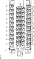
- Fig. 1 is a top view illustrating an overview of the passenger cabin of an aircraft equipped with the seat unit for an aircraft according to the present embodiment.
- the upper left side in the figure is the leading side of the aircraft and the right side is the rear side of the aircraft.
- the aircraft 1 has a plurality of seat units 10 for an aircraft arranged in a line on the floor 2 in the center, and single seats 20 are arranged in a row on both window sides, respectively.
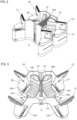
- FIG. 2 is a perspective view of a seat unit 10 for an aircraft as viewed from diagonally above.
- FIG. 3 is a perspective view of a seat unit 10 for an aircraft as viewed from above and in front.
- FIG. 4 is a diagram illustrating a seat unit 10 for an aircraft as viewed from directly above, and illustrates a seat state.
- FIG. 5 is a diagram illustrating a seat state 10 for an aircraft as viewed from directly above, and illustrates a bed state.
- the seat unit 10 for an aircraft includes a front wall 11 and a rear wall 12 which are erected from the floor 2 in parallel, a first seat 13 and a second seat 14 arranged adjacent to each other on the floor 2 between the front wall 11 and the rear wall 12, an intermediate portion 15 arranged between the first seat 13 and the second seat 14, a first side table 16 arranged beside the first seat 13, and a second side table 17 arranged beside the second seat 14.
- the front wall 11 and the rear wall 12 have a common shape. Due to this, the rear wall 12 of the front side seat unit 10 can also serve as the front wall 11 of the rear side seat unit 10 adjacent thereto.
- the seat unit 10 is described as having a front wall 11 and a rear wall 12.
- the first seat 13, the second seat 14, and the rear wall 12 are supplied from the interior manufacturer as a single seat unit set, and by arranging them in front and behind each other and attaching them to the aircraft 1, the rear wall 12 can also be used as the front wall 11.
- the front wall 11 has, on both sides thereof, trapezoidal columnar protrusions 11a and 11b protruding forward.
- the rear wall 12 has, on both sides thereof, trapezoidal columnar protrusions 12a and 12b protruding forward.
- the interior of the protrusions 12a, 12b of the rear wall 12 is hollow, the first side table 16 is placed on an upper surface of the protrusion 12a, and the second side table 17 is placed on an upper surface of the protrusion 12b. The same applies to the front wall 11.
- the front wall 11 and the rear wall 12 have a substantially W like shape when viewed from above.
- the axis line X1 of the first seat 13 and the axis line X2 of the second seat 14 are angled to opposite sides at the same angle with respect to the traversal direction D of the aircraft 1.
- the intermediate portion 15 is provided by utilizing this space in order to make effective use of the space.
- the intermediate portion 15 is disposed in the triangular prism-shaped space between the front wall 11, the first seat 13, and the second seat 14 so as to be in contact therewith.
- the first seat 13 and the second seat 14 have the same structure, they may also be different from each other. It should be noted that the first seat 13 or the second seat 14 may be used as the seat 20 on the window side.
- the first seat 13 has a first seating portion 13a and a first backrest 13b.
- the first backrest 13b is pivotally connected to the rear end of the first seating portion 13a.
- a reclining mechanism 13c (see FIG. 6 , which will be described later) is driven and controlled, and at the same time that the first backrest 13b reclines backward with respect to the first seating portion 13a, the first seating portion 13a slides horizontally forward, and the upper surfaces of the first seating portion 13a and the first backrest 13b become horizontally flat.
- This is referred to as the bed state (see FIG. 5 ).
- a part of the first seating portion 13a enters the inside of the protrusion 11a. That is, the inside of the protrusion 11a becomes a part of the use space of the user, and the user can extend his/her feet and lie down on the first seat 13.
- the second seat 14 has a second seating portion 14a and a second backrest 14b.
- the second backrest 14b is pivotally connected to the rear end of the second seating portion 14a.
- a reclining mechanism 14c (see FIG. 6 , while will be described later) is driven and controlled, and at the same time that the second backrest 14b reclines backward with respect to the second seating portion 14a, the second seating portion 14a slides horizontally forward, and the upper surfaces of the second seating portion 14a and the second backrest 14b become horizontally flat.
- This is referred to as the bed state (see FIG. 5 ).
- a part of the second seating portion 14a enters the inside of the protrusion 11b. That is, the inside of the protrusion 11b becomes a part of the use space of the user, and the user can extend his/her feet and lie down on the second seat 14.
- the intermediate portion 15 includes a pedestal 15a that has a triangular prism shape disposed on the first seat 13 side, a pedestal 15b that has a triangular prism shape disposed on the second seat 14 side, a rectangular parallelepiped support portion 15c disposed between the pedestals 15a and 15b, and a partition plate 15d supported by the support portion 15c.
- the support portion 15c and the partition plate 15d extend from the rear surface of the front wall 11 to the front surface of the rear wall 12.
- the end portions of the partition plate 15d are engaged with a vertical groove 12c of the rear surface of the front wall 11 and a vertical groove 12c on the rear surface of the rear wall 12, and can be raised and lowered by being guided by these.
- the support portion 15c which is covered with a material having cushion properties similar to the pedestals 15a and 15b, includes a slit 15f opening at the center of the upper surface.
- the partition plate 15d is disposed so as to be slidable in the vertical direction within the slit 15f.
- the partition plate 15d is preferably made of translucent or opaque resin, for example.
- the upper end of the partition plate 15d is above the eye level (usually 10 cm or more below the upper end of the first backrest 13b or the second backrest 14b) of the users seated on the first seating portion 13a or the second seating portion 14a in the seat state.
- the eye level usually 10 cm or more below the upper end of the first backrest 13b or the second backrest 14b
- a user or an attendant can manually or electronically slide the support portion 15c downward with respect to the pedestals 15a and 15b, and slide the partition plate 15d downward with respect to the support portion 15c to house them internally.
- This state is referred to as an open state.
- the open state as illustrated in FIG. 7 , the height positions of the upper surfaces of the pedestals 15a and 15b and the upper surface of the support portion 15c substantially coincide.
- the height of the upper surface of the support portion 15c and the height of the upper end of the partition plate 15d substantially coincide. That is, as illustrated in FIG. 7 , the entire upper surface of the intermediate portion 15 has a uniform height.
- the height of the first backrest 13b and the second backrest 14b substantially coincide with the height of the upper surface of the intermediate portion 15.
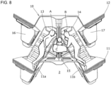
- FIG. 8 illustrates a use example of the space obtained in the seat unit 10.
- a state is illustrated in which a user A lies on the first seat 13 in the bed state, a user B lies on the second seat 14 in the bed state, and an infant C lies on the intermediate portion 15 in which the partition plate 15d and the support portion 15c have been lowered. Since the intermediate portion 15 becomes flat by lowering the support portion 15c and the partition plate 15d into the open state, the intermediate portion 15 does not get in the way when the infant C lies down. Further, as illustrated by the dotted line, since the feet of the users A and B can be housed in the protrusions 11a and 11b of the front wall 11, the user can extend his/her feet and assume a comfortable posture.
- the seat unit for an aircraft it is not necessary to reserve an adult seat for the infant C, and it is possible to reduce the economic burden on the users A and B who accompany the infant C.
- the support portion 15c by providing the support portion 15c, it is possible to lift the upper end of the partition plate 15d to a high position in the shielded state while retaining the intermediate portion 15 in a low position. That is, supposing that there were no support portion 15c, in a case that the height of the upper surface of the intermediate portion 15 (the height of the upper end of the partition plate 15d) were made to coincide with the upper surface height of the first backrest 13b or the second backrest 14b in the bed state, the height of the partition plate 15d would only be twice the height of the intermediate portion 15 in the shielded state, at maximum. In such a case, since the height of the partition plate 15d in the shielded state falls below the eye level of a user sitting on the seating portion, it becomes impossible to secure a private space between the first seat 13 side and the second seat 14 side.
- the intermediate portion 15 is provided with a support portion 15c in a two-stage lifting structure, the support portion 15c is slid with respect to the pedestals 15a and 15b, and the partition plate 15d is slid with respect to the support portion 15c.
- the support portion 15c is slid with respect to the pedestals 15a and 15b
- the partition plate 15d is slid with respect to the support portion 15c.
- the intermediate portion 15 can be used not only for infants, but also for the purpose of keeping valuable musical instruments within sight when, for example, a musician or the like boards.
- the intermediate portion 15 may be used for placing a shogi board, a chess board, or the like, for example, when the passenger in the first seat 13 and the passenger in the second seat 14 wish to play a shogi game or a chess game.
- the upper end of the partition plate 15d in the shielded state may be lower than the upper surface of the intermediate portion 15.
Landscapes
- Engineering & Computer Science (AREA)
- Aviation & Aerospace Engineering (AREA)
- Seats For Vehicles (AREA)
- Special Chairs (AREA)
Description
- The present invention relates to a seat unit for an aircraft.
- Among seats provided in aircraft, seats for first class or business class, for example, are known that have seat structures capable of selectively changing between a sitting state in which a backrest stands upright, and a state in which the backrest or the like is reclined to be in a horizontal position that can be used as a bed.
- On the other hand, as illustrated in
Patent Document 1, there is also known an aircraft seat structure which allows a partition plate between seats arranged in a traversal direction to be moved up and down. According to such a configuration, when another person sits in each seat for example, a private space can be secured for each seat by raising the partition plate. On the other hand, when two passengers such as family members sit side by side, lowering the partition plate creates a single space that can be shared by the two passengers, such that it becomes possible for passengers to use the partition plate accordingly. -
- [Patent Document 1]
International Patent Publication No. WO 2017/168746 - [Patent Document 2]
International Patent Publication No. WO 2019/070194 describes a seat unit comprising a first seat in which a first backrest is pivotable with respect to a first seat portion and is capable of changing forms between a seat state and a bed state, The seat unit further comprises a second seat, disposed adjacent to the first seat, and in which a second backrest is pivotable with respect to a second seating portion between a seat state and a bed state. - [Patent Document 3]
American Patent Publication No. US 2010116936 describes a seat unit comprising a first seat, a second seat disposed adjacent to the first seat and an intermediate portion arranged between the first seat and the second seat. - Incidentally, in recent years, the diversification of passengers using aircrafts is progressing, and cases in which families accompanied by infants, for example, board the aircraft are increasing. In such cases, when using a business seat, for example, there are times when adult fees, or an amount close thereto, are charged even for infants, and the economic burden of the passengers becomes excessive. On the other hand, since the body type and weight of infants are a fraction of those of adults, there has been demand for the introduction of small, dedicated seats adapted to the body types of infants, in addition to a low price setting. However, since the boarding of families accompanied by infants is not guaranteed at all times, the introduction into an aircraft of seats dedicated to infants may lead to a decrease in the seat occupancy rate.
- It is therefore an object of the present invention to provide a seat unit for an aircraft that can handle the diversification of passengers and effectively utilize the space in the passenger cabin.
- In order to achieve the above object, a seat unit for an aircraft is defined in
claim 1. The seat unit for an aircraft according to the present invention includes a first seat in which a first backrest is pivotable with respect to a first seating portion and that is capable of changing forms between a seat state in which passengers can sit and a bed state in which the first seating portion and the first backrest are flat, a second seat disposed adjacent to the first seat, in which a second backrest is pivotable with respect to a second seating portion and that is capable of changing forms between a seat state in which passengers can sit and a bed state in which the second seating portion and the second backrest are flat, and an intermediate portion arranged between the first seat and the second seat, wherein, in the bed state, the intermediate portion is adjacent to the first backrest and the second backrest while a height of an upper surface of the intermediate portion substantially coincides with a height of the first backrest and the second backrest, the intermediate portion includes a vertically movable partition plate, and in a state in which the partition plate is housed in the intermediate portion, an upper end of the partition plate substantially coincides with or is located at or below an upper surface of the intermediate portion, and when the partition plate is raised, an upper end of the partition plate can move to a position above eye level of a user seated on at least the first seating portion or the second seating portion in the seat state. - According to the present invention, it is possible to provide a seat unit for an aircraft that can handle the diversification of passengers and effectively utilize the space in the passenger cabin.
-
- [
Fig. 1] Figure 1 is a top view illustrating an overview of the passenger cabin of an aircraft equipped with a seat unit for an aircraft according to the present embodiment. - [
Fig. 2] Figure 2 is perspective view of aseat unit 10 for an aircraft as viewed from diagonally above. - [
Fig. 3] Figure 3 is a perspective view of aseat unit 10 for an aircraft as viewed from above and in front. - [
Fig. 4] Figure 4 is a diagram illustrating aseat unit 10 for an aircraft as viewed from directly above, and illustrates a seat state. - [
Fig. 5] Figure 5 is a diagram illustrating aseat unit 10 for an aircraft as viewed from directly above, and illustrates a bed state. - [
Fig. 6] Figure 6 is a cross-sectional view of the line A-A ofFIG. 3 , and illustrates a state in which the partition plate is raised to the maximum position (a shielded state). - [
Fig. 7] Figure 7 is a cross-sectional view of the line A-A ofFIG. 3 , and illustrates a state in which the partition plate is housed in the intermediate portion (an open state). - [
Fig. 8] Figure 8 is a diagram illustrating a use example of the seat unit. - The embodiments of the present invention will be described below with reference to the drawings. It should be noted that, in the present specification, "substantially coincide in height" means that the difference in height is within 2cm (preferably within 1cm). In addition, the terms "forward" and "rearward" refer to the traversal direction of the aircraft and a direction opposite to the traversal direction, respectively.
-
Fig. 1 is a top view illustrating an overview of the passenger cabin of an aircraft equipped with the seat unit for an aircraft according to the present embodiment. InFIG. 1 , the upper left side in the figure is the leading side of the aircraft and the right side is the rear side of the aircraft. Theaircraft 1 has a plurality ofseat units 10 for an aircraft arranged in a line on thefloor 2 in the center, andsingle seats 20 are arranged in a row on both window sides, respectively. -
FIG. 2 is a perspective view of aseat unit 10 for an aircraft as viewed from diagonally above.FIG. 3 is a perspective view of aseat unit 10 for an aircraft as viewed from above and in front.FIG. 4 is a diagram illustrating aseat unit 10 for an aircraft as viewed from directly above, and illustrates a seat state.FIG. 5 is a diagram illustrating aseat state 10 for an aircraft as viewed from directly above, and illustrates a bed state. - In
FIG. 2 and FIG. 3 , theseat unit 10 for an aircraft includes afront wall 11 and arear wall 12 which are erected from thefloor 2 in parallel, afirst seat 13 and asecond seat 14 arranged adjacent to each other on thefloor 2 between thefront wall 11 and therear wall 12, anintermediate portion 15 arranged between thefirst seat 13 and thesecond seat 14, a first side table 16 arranged beside thefirst seat 13, and a second side table 17 arranged beside thesecond seat 14. - The
front wall 11 and therear wall 12 have a common shape. Due to this, therear wall 12 of the frontside seat unit 10 can also serve as thefront wall 11 of the rearside seat unit 10 adjacent thereto. For convenience of description, theseat unit 10 is described as having afront wall 11 and arear wall 12. However, in practice, thefirst seat 13, thesecond seat 14, and therear wall 12 are supplied from the interior manufacturer as a single seat unit set, and by arranging them in front and behind each other and attaching them to theaircraft 1, therear wall 12 can also be used as thefront wall 11. - The
front wall 11 has, on both sides thereof, trapezoidalcolumnar protrusions rear wall 12 has, on both sides thereof, trapezoidalcolumnar protrusions protrusions rear wall 12 is hollow, the first side table 16 is placed on an upper surface of theprotrusion 12a, and the second side table 17 is placed on an upper surface of theprotrusion 12b. The same applies to thefront wall 11. - As illustrated in
FIG. 4 , thefront wall 11 and therear wall 12 have a substantially W like shape when viewed from above. In addition, the axis line X1 of thefirst seat 13 and the axis line X2 of thesecond seat 14 are angled to opposite sides at the same angle with respect to the traversal direction D of theaircraft 1. As a result, it is possible to reduce the dimensions of thefirst seat 13 andsecond seat 14 along the traveling direction D when in the bed state (FIG. 5 ), and a large number of seat units can be mounted on theaircraft 1. On the other hand, by arranging thefirst seat 13 and thesecond seat 14 in such a manner, a substantially triangular prism-shaped space is created between thefirst seat 13 and thesecond seat 14. Theintermediate portion 15 is provided by utilizing this space in order to make effective use of the space. - The
intermediate portion 15 is disposed in the triangular prism-shaped space between thefront wall 11, thefirst seat 13, and thesecond seat 14 so as to be in contact therewith. Although thefirst seat 13 and thesecond seat 14 have the same structure, they may also be different from each other. It should be noted that thefirst seat 13 or thesecond seat 14 may be used as theseat 20 on the window side. - The
first seat 13 has afirst seating portion 13a and afirst backrest 13b. Thefirst backrest 13b is pivotally connected to the rear end of thefirst seating portion 13a. By means of a user operating a switch (not shown in the figures), areclining mechanism 13c (seeFIG. 6 , which will be described later) is driven and controlled, and at the same time that thefirst backrest 13b reclines backward with respect to thefirst seating portion 13a, thefirst seating portion 13a slides horizontally forward, and the upper surfaces of thefirst seating portion 13a and thefirst backrest 13b become horizontally flat. This is referred to as the bed state (seeFIG. 5 ). When in the bed state, a part of thefirst seating portion 13a enters the inside of theprotrusion 11a. That is, the inside of theprotrusion 11a becomes a part of the use space of the user, and the user can extend his/her feet and lie down on thefirst seat 13. - From this bed state, by means of the user operating the switch (not shown in the figures) in reverse, at the same time that the
first backrest 13b rises with respect to thefirst seating portion 13a, thefirst seating portion 13a slides backward, and thefirst backrest 13b becomes angled with respect to the first seating portion 13a.This is referred to as the seat state (seeFIG. 3 ,FIG. 4 ). In the seat state, thereclining mechanism 13c may slightly lift the front end of thefirst seating portion 13a. This allows the user to sit on thefirst seating portion 13a with a comfortable posture. - Similarly, the
second seat 14 has asecond seating portion 14a and asecond backrest 14b. Thesecond backrest 14b is pivotally connected to the rear end of thesecond seating portion 14a. By means of a user operating a switch (not shown in the figures), areclining mechanism 14c (seeFIG. 6 , while will be described later) is driven and controlled, and at the same time that thesecond backrest 14b reclines backward with respect to thesecond seating portion 14a, thesecond seating portion 14a slides horizontally forward, and the upper surfaces of thesecond seating portion 14a and thesecond backrest 14b become horizontally flat. This is referred to as the bed state (seeFIG. 5 ). When in the bed state, a part of thesecond seating portion 14a enters the inside of theprotrusion 11b. That is, the inside of theprotrusion 11b becomes a part of the use space of the user, and the user can extend his/her feet and lie down on thesecond seat 14. - From this bed state, by means of the user operating the switch (not shown in the figures) in reverse, at the same time that the
second backrest 14b rises with respect to thesecond seating portion 14a, thesecond seating portion 14a slides backward, and thesecond backrest 14b becomes angled with respect to thesecond seating portion 14a. This is referred to as the seat state (seeFIG. 3 andFIG. 4 ). In the seat state, thereclining mechanism 14c may slightly lift the front end of thesecond seating portion 14a. This allows the user to sit on thesecond seating portion 14a with a comfortable posture. It should be noted that, with regard to thereclining mechanisms - In
FIG. 5 , theintermediate portion 15 includes apedestal 15a that has a triangular prism shape disposed on thefirst seat 13 side, apedestal 15b that has a triangular prism shape disposed on thesecond seat 14 side, a rectangularparallelepiped support portion 15c disposed between thepedestals partition plate 15d supported by thesupport portion 15c. Thesupport portion 15c and thepartition plate 15d extend from the rear surface of thefront wall 11 to the front surface of therear wall 12. As illustrated inFIG. 5 , the end portions of thepartition plate 15d are engaged with avertical groove 12c of the rear surface of thefront wall 11 and avertical groove 12c on the rear surface of therear wall 12, and can be raised and lowered by being guided by these. -
FIG. 6 and FIG. 7 are cross-sectional views taken along the line A-A ofFIG. 3 . In the figures, thepedestals support portion 15c is disposed on theguide 15e between thepedestals pedestals - The
support portion 15c, which is covered with a material having cushion properties similar to thepedestals slit 15f opening at the center of the upper surface. Thepartition plate 15d is disposed so as to be slidable in the vertical direction within theslit 15f. Thepartition plate 15d is preferably made of translucent or opaque resin, for example. - As an example, in the case that the users sitting in the
first seat 13 and thesecond seat 14 are complete stranger, it is desirable to define a private space for each of the first seat and thesecond seat 14. In such a case, the user or an attendant manually or electrically slides thesupport portion 15c upward with respect to thepedestals partition plate 15d upward with respect to thesupport portion 15c. Such a state is referred to as a shielded state, and is illustrated inFIG. 2 andFIG. 6 . In the shielded state, the upper end of thepartition plate 15d is above the eye level (usually 10 cm or more below the upper end of thefirst backrest 13b or thesecond backrest 14b) of the users seated on thefirst seating portion 13a or thesecond seating portion 14a in the seat state. As a result, a private space for a user sitting in thefirst seat 13 or thesecond seat 14 is secured. - On the other hand, a user or an attendant can manually or electronically slide the
support portion 15c downward with respect to thepedestals partition plate 15d downward with respect to thesupport portion 15c to house them internally. This state is referred to as an open state. In the open state, as illustrated inFIG. 7 , the height positions of the upper surfaces of thepedestals support portion 15c substantially coincide. In addition, the height of the upper surface of thesupport portion 15c and the height of the upper end of thepartition plate 15d substantially coincide. That is, as illustrated inFIG. 7 , the entire upper surface of theintermediate portion 15 has a uniform height. - While maintaining such a state, as illustrated in
FIG. 5 , when thefirst seat 13 and thesecond seat 14 are put into the bed state, the height of thefirst backrest 13b and thesecond backrest 14b substantially coincide with the height of the upper surface of theintermediate portion 15. - Then, a wide space having a flat upper surface formed by the
first seat 13, thesecond seat 14, and theintermediate portion 15 is formed between thefront wall 11 and therear wall 12. -
FIG. 8 illustrates a use example of the space obtained in theseat unit 10. A state is illustrated in which a user A lies on thefirst seat 13 in the bed state, a user B lies on thesecond seat 14 in the bed state, and an infant C lies on theintermediate portion 15 in which thepartition plate 15d and thesupport portion 15c have been lowered. Since theintermediate portion 15 becomes flat by lowering thesupport portion 15c and thepartition plate 15d into the open state, theintermediate portion 15 does not get in the way when the infant C lies down. Further, as illustrated by the dotted line, since the feet of the users A and B can be housed in theprotrusions front wall 11, the user can extend his/her feet and assume a comfortable posture. - According to the seat unit for an aircraft according to the present embodiment, it is not necessary to reserve an adult seat for the infant C, and it is possible to reduce the economic burden on the users A and B who accompany the infant C.
- In contrast, when people who are unfamiliar with each other are seated in the
first seat 13 and thesecond seat 14, respectively, as illustrated inFIG. 2 andFIG. 6 , by raising thesupport portion 15c and thepartition plate 15d into the shielded state, it is possible to secure respective private spaces. In other words, since theseat unit 10 can be commonly used regardless of whether the user is accompanied by an infant or not, the seat occupancy rate of the aircraft can be improved. - Furthermore, according to the present embodiment, by providing the
support portion 15c, it is possible to lift the upper end of thepartition plate 15d to a high position in the shielded state while retaining theintermediate portion 15 in a low position. That is, supposing that there were nosupport portion 15c, in a case that the height of the upper surface of the intermediate portion 15 (the height of the upper end of thepartition plate 15d) were made to coincide with the upper surface height of thefirst backrest 13b or thesecond backrest 14b in the bed state, the height of thepartition plate 15d would only be twice the height of theintermediate portion 15 in the shielded state, at maximum. In such a case, since the height of thepartition plate 15d in the shielded state falls below the eye level of a user sitting on the seating portion, it becomes impossible to secure a private space between thefirst seat 13 side and thesecond seat 14 side. - Accordingly, in the present embodiment, the
intermediate portion 15 is provided with asupport portion 15c in a two-stage lifting structure, thesupport portion 15c is slid with respect to thepedestals partition plate 15d is slid with respect to thesupport portion 15c. As a result, theoretically, it is possible to raise the upper end of thepartition plate 15d up to a height position of approximately three times the height of theintermediate portion 15. It should be noted that, by providing a plurality of support portions, a three-stage or more lifting structure can be provided. - Furthermore, the
intermediate portion 15 can be used not only for infants, but also for the purpose of keeping valuable musical instruments within sight when, for example, a musician or the like boards. Alternatively, theintermediate portion 15 may be used for placing a shogi board, a chess board, or the like, for example, when the passenger in thefirst seat 13 and the passenger in thesecond seat 14 wish to play a shogi game or a chess game. - In addition, it is also possible to apply various modifications to the above examples without departing from the scope of the present invention. For example, the upper end of the
partition plate 15d in the shielded state may be lower than the upper surface of theintermediate portion 15. - 1 : Aircraft, 2 : Floor, 11 : Front wall, 12 : Rear wall, 13 : First seat, 14 : Second seat, 15 : Intermediate portion, 15c: Support portion, 15d: Partition plate, 16 : First side table, 17 : Second side table
Claims (4)
- A seat unit (10) for an aircraft comprising:a first seat (13) comprising a first backrest (13b) and a first seating portion (13a) in which said first backrest (13b) is pivotable with respect to the first seating portion (13a) and is capable of changing forms between a seat state in which passengers can sit and a bed state in which the first seating portion (13a) and the first backrest (13b) are flat;a second seat (14) disposed adjacent to the first seat, the second seat comprising a second backrest (14b) and a second seating portion (14a), in which the second backrest (14b) is pivotable with respect to the second seating portion (14a) and is capable of changing forms between a seat state in which passengers can sit and a bed state in which the second seating portion (14a) and the second backrest (14b) are flat; andan intermediate portion (15) arranged between the first seat (13) and the second seat (14),when the first seat (13) and the second seat (14) are in the bed state, the intermediate portion (15) is adjacent to the first backrest (13b) and the second backrest (14b) while a height of an upper surface of the intermediate portion (15) substantially coincides with a height of the first backrest (13b) and the second backrest (14b),the intermediate portion (15) includes a first pedestal (15a) having a triangular prism shape and being disposed (15a) on the first seat (13) side and a second pedestal (15b) having a triangular prism shape and being disposed on the second seat (14) side, as well as a rectangular parallelepiped support portion (15c) disposed between the first and second pedestals (15a, 15b) and a partition plate (15d), supported by the support portion (15c) and vertically movable between a housed state, in which the partition plate (15d) is housed in the support portion (15c) of intermediate portion (15), and a raised state, andwhen in the housed state, an upper end of the partition plate (15d) substantially coincides with or is located at or below the upper surface of the support portion (15c) of the intermediate portion (15), and when in the raised state, the upper end of the partition plate (15d) can move to a position above eye level of a user seated on at least the first seating portion (13a) or the second seating portion (14a) in the seat state; andthe height positions of upper surfaces of the first and second pedestals (15a, 15b) and the upper surface of the support portion (15c) substantially coincide so that the entire upper surface of the intermediate portion (15) has a uniform height; andthe pedestals (15a, 15b), and the support portion (15c) are covered with a material having cushion properties.
- The seat unit (10) for an aircraft according to claim 1, wherein:
the support member (15c) is movable upward from the intermediate portion with respect to the first and second pedestals (15a, 15b) and the partition plate (15d) is movable upward from the support member. - The seat unit for an aircraft according to claim 1 or 2, wherein:
an axis (X1) of the first seat (13) and an axis (X2) of the second seat (14) are angled to opposite sides with respect to a traversal direction of the aircraft, and the intermediate portion is disposed in a triangular prism shaped space between the first seat (13) and the second seat (14). - The seat unit for an aircraft according to any of claim 1 to 3:wherein the first seat (13) further comprises a first user operated switch and a first reclining mechanisms (13c), the first user operated switch being configured to drive and control the first reclining mechanisms (13c),wherein the second seat (14) further comprises a second user operated switch and a second reclining mechanisms (14c), the second user operated switch being configured to drive and control the second reclining mechanisms (14c), andwherein, when a form change from the seat state to the bed state is performed and at the same time as a user operating the first user operated switch, the first backrest (13b) reclines backward with respect to the first seating portion (13a), the first seating portion (13a) slides horizontally forward, and the upper surfaces of the first seating portion (13a) and the first backrest (13b) become horizontally flat andwherein, when a form change from the seat state to the bed state is performed and at the same time as a user operating the second user operated switch, the second backrest (14b) reclines backward with respect to the second seating portion (14a), the second seating portion (14a) slides horizontally forward, and the upper surfaces of the second seating portion (14a) and the second backrest (14b) become horizontally flat.
Applications Claiming Priority (1)
| Application Number | Priority Date | Filing Date | Title |
|---|---|---|---|
| PCT/JP2018/012405 WO2019186689A1 (en) | 2018-03-27 | 2018-03-27 | Seat unit for aircraft |
Publications (3)
| Publication Number | Publication Date |
|---|---|
| EP3778398A1 EP3778398A1 (en) | 2021-02-17 |
| EP3778398A4 EP3778398A4 (en) | 2021-10-20 |
| EP3778398B1 true EP3778398B1 (en) | 2025-01-08 |
Family
ID=68062595
Family Applications (1)
| Application Number | Title | Priority Date | Filing Date |
|---|---|---|---|
| EP18912749.1A Active EP3778398B1 (en) | 2018-03-27 | 2018-03-27 | Seat unit for aircraft |
Country Status (4)
| Country | Link |
|---|---|
| US (1) | US20210009271A1 (en) |
| EP (1) | EP3778398B1 (en) |
| JP (1) | JP6975318B2 (en) |
| WO (1) | WO2019186689A1 (en) |
Families Citing this family (4)
| Publication number | Priority date | Publication date | Assignee | Title |
|---|---|---|---|---|
| EP3768597A1 (en) * | 2018-03-23 | 2021-01-27 | Adient Aerospace, LLC | Seat unit and passenger seating arrangement provided within a vehicle cabin |
| KR20250026279A (en) * | 2022-06-27 | 2025-02-25 | 싱가포르 에어라인스 리미티드 | Aircraft cabin |
| US20240351689A1 (en) * | 2023-04-24 | 2024-10-24 | B/E Aerospace, Inc. | Passenger seating system |
| US20250051012A1 (en) * | 2023-08-07 | 2025-02-13 | B/E Aerospace, Inc. | Conjoinable reverse herringbone passenger seat |
Citations (1)
| Publication number | Priority date | Publication date | Assignee | Title |
|---|---|---|---|---|
| EP3554947B1 (en) * | 2016-12-14 | 2021-01-27 | Safran Seats | Arrangement of individual seats for passengers of an aeroplane |
Family Cites Families (14)
| Publication number | Priority date | Publication date | Assignee | Title |
|---|---|---|---|---|
| CA2281494A1 (en) * | 1997-02-20 | 1998-08-27 | Philip Haith | Improvements in transport accommodation |
| US7578470B2 (en) * | 2006-04-21 | 2009-08-25 | Be Aerospace, Inc. | Passenger seating arrangement |
| US7721991B2 (en) * | 2006-10-12 | 2010-05-25 | Be Aerospace, Inc. | Translatable and rotatable passenger seat |
| GB0704546D0 (en) * | 2007-03-08 | 2007-04-18 | Contour Premium Aircraft Seati | Adjustable seat |
| US20090146004A1 (en) * | 2007-12-06 | 2009-06-11 | B E Aerospace, Inc. | Aircraft seating arrangement and seat |
| GB0903744D0 (en) * | 2009-03-04 | 2009-04-15 | Virgin Atlantic Airways Ltd | A seating insallation for a passenger vehicle |
| GB2469180B8 (en) * | 2009-03-23 | 2016-06-08 | Air New Zealand Ltd | Vehicle seating arrangement |
| FR2953168B1 (en) * | 2009-12-02 | 2012-01-06 | Eads Sogerma | CONVERTIBLE SEAT IN SLEEVE |
| EP2825458B1 (en) * | 2012-03-14 | 2018-11-28 | B/E Aerospace Inc. | Aircraft passenger suite with combination bed |
| FR3003540B1 (en) * | 2013-03-25 | 2015-05-29 | Eads Sogerma | ARRANGEMENT OF CONVERTIBLE SEATS IN LAYERS |
| JP6389900B2 (en) * | 2016-04-01 | 2018-09-12 | 株式会社ジャムコ | Aircraft seat structure |
| FR3055128A1 (en) * | 2016-08-17 | 2018-02-23 | Zodiac Seats France | ARRANGEMENT OF SEATS FOR INCREASING THE INTIMACY OF PASSENGERS, IN PARTICULAR AN AIRCRAFT |
| WO2018051496A1 (en) * | 2016-09-16 | 2018-03-22 | 株式会社ジャムコ | Aircraft seat unit and multiple seat structure |
| KR102377392B1 (en) * | 2017-10-03 | 2022-03-22 | 싱가포르 에어라인스 리미티드 | aircraft seat |
-
2018
- 2018-03-27 EP EP18912749.1A patent/EP3778398B1/en active Active
- 2018-03-27 WO PCT/JP2018/012405 patent/WO2019186689A1/en not_active Ceased
- 2018-03-27 JP JP2020510232A patent/JP6975318B2/en active Active
- 2018-03-27 US US16/981,523 patent/US20210009271A1/en not_active Abandoned
Patent Citations (1)
| Publication number | Priority date | Publication date | Assignee | Title |
|---|---|---|---|---|
| EP3554947B1 (en) * | 2016-12-14 | 2021-01-27 | Safran Seats | Arrangement of individual seats for passengers of an aeroplane |
Also Published As
| Publication number | Publication date |
|---|---|
| JPWO2019186689A1 (en) | 2021-01-07 |
| EP3778398A4 (en) | 2021-10-20 |
| WO2019186689A1 (en) | 2019-10-03 |
| JP6975318B2 (en) | 2021-12-01 |
| US20210009271A1 (en) | 2021-01-14 |
| EP3778398A1 (en) | 2021-02-17 |
Similar Documents
| Publication | Publication Date | Title |
|---|---|---|
| US11787545B2 (en) | Platform first class | |
| US9126689B2 (en) | Vehicle passenger seating | |
| CN106103277B (en) | Seat unit for vehicle cabin | |
| US8342450B2 (en) | Seating arrangement of a vehicle compartment | |
| FI114016B (en) | The seat unit | |
| CA2867297C (en) | Premium class aircraft passenger suite with separate seating areas | |
| JP5248325B2 (en) | Aircraft passenger seat | |
| CN104245506B (en) | Airplane passenger suite with sectional bed | |
| EP3778398A1 (en) | Seat unit for aircraft | |
| US9327837B2 (en) | Modular airplane seat unit | |
| US20110226900A1 (en) | Seating Arrangement, Seat Unit, Tray Table and Seating System | |
| CN104507746A (en) | Passenger suite seating arrangement with moveable video monitor | |
| US20120112500A1 (en) | Vehicle Seating Apparatus | |
| EP3684690B1 (en) | Aircraft passenger room | |
| CN121778158A (en) | Passenger module, passenger seating arrangement | |
| EP2783983A1 (en) | Passenger module for a seating array for an aircraft cabin | |
| CN118215620A (en) | Seat systems for aircraft | |
| WO2011141890A1 (en) | Arrangement for passenger | |
| HK40022729B (en) | Aircraft passenger room | |
| HK40022729A (en) | Aircraft passenger room | |
| HK40032899A (en) | A passenger seating arrangement having access for disabled passengers |
Legal Events
| Date | Code | Title | Description |
|---|---|---|---|
| STAA | Information on the status of an ep patent application or granted ep patent |
Free format text: STATUS: THE INTERNATIONAL PUBLICATION HAS BEEN MADE |
|
| PUAI | Public reference made under article 153(3) epc to a published international application that has entered the european phase |
Free format text: ORIGINAL CODE: 0009012 |
|
| STAA | Information on the status of an ep patent application or granted ep patent |
Free format text: STATUS: REQUEST FOR EXAMINATION WAS MADE |
|
| 17P | Request for examination filed |
Effective date: 20200922 |
|
| AK | Designated contracting states |
Kind code of ref document: A1 Designated state(s): AL AT BE BG CH CY CZ DE DK EE ES FI FR GB GR HR HU IE IS IT LI LT LU LV MC MK MT NL NO PL PT RO RS SE SI SK SM TR |
|
| AX | Request for extension of the european patent |
Extension state: BA ME |
|
| RIN1 | Information on inventor provided before grant (corrected) |
Inventor name: AKUTSU, YUICHI Inventor name: IGARI, AMON Inventor name: KATAKURA, SACHIKO Inventor name: KINOSHITA, MICHIO Inventor name: MATSUMOTO, MANABU Inventor name: HAGIWARA, HISAYA |
|
| DAV | Request for validation of the european patent (deleted) | ||
| DAX | Request for extension of the european patent (deleted) | ||
| A4 | Supplementary search report drawn up and despatched |
Effective date: 20210921 |
|
| RIC1 | Information provided on ipc code assigned before grant |
Ipc: B64D 11/06 20060101AFI20210915BHEP |
|
| STAA | Information on the status of an ep patent application or granted ep patent |
Free format text: STATUS: EXAMINATION IS IN PROGRESS |
|
| 17Q | First examination report despatched |
Effective date: 20230313 |
|
| GRAP | Despatch of communication of intention to grant a patent |
Free format text: ORIGINAL CODE: EPIDOSNIGR1 |
|
| STAA | Information on the status of an ep patent application or granted ep patent |
Free format text: STATUS: GRANT OF PATENT IS INTENDED |
|
| INTG | Intention to grant announced |
Effective date: 20240812 |
|
| GRAS | Grant fee paid |
Free format text: ORIGINAL CODE: EPIDOSNIGR3 |
|
| GRAA | (expected) grant |
Free format text: ORIGINAL CODE: 0009210 |
|
| STAA | Information on the status of an ep patent application or granted ep patent |
Free format text: STATUS: THE PATENT HAS BEEN GRANTED |
|
| AK | Designated contracting states |
Kind code of ref document: B1 Designated state(s): AL AT BE BG CH CY CZ DE DK EE ES FI FR GB GR HR HU IE IS IT LI LT LU LV MC MK MT NL NO PL PT RO RS SE SI SK SM TR |
|
| P01 | Opt-out of the competence of the unified patent court (upc) registered |
Free format text: CASE NUMBER: APP_63704/2024 Effective date: 20241201 |
|
| REG | Reference to a national code |
Ref country code: GB Ref legal event code: FG4D |
|
| REG | Reference to a national code |
Ref country code: CH Ref legal event code: EP |
|
| REG | Reference to a national code |
Ref country code: DE Ref legal event code: R096 Ref document number: 602018078448 Country of ref document: DE |
|
| REG | Reference to a national code |
Ref country code: IE Ref legal event code: FG4D |
|
| REG | Reference to a national code |
Ref country code: LT Ref legal event code: MG9D |
|
| REG | Reference to a national code |
Ref country code: NL Ref legal event code: MP Effective date: 20250108 |
|
| REG | Reference to a national code |
Ref country code: AT Ref legal event code: MK05 Ref document number: 1758176 Country of ref document: AT Kind code of ref document: T Effective date: 20250108 |
|
| PG25 | Lapsed in a contracting state [announced via postgrant information from national office to epo] |
Ref country code: NL Free format text: LAPSE BECAUSE OF FAILURE TO SUBMIT A TRANSLATION OF THE DESCRIPTION OR TO PAY THE FEE WITHIN THE PRESCRIBED TIME-LIMIT Effective date: 20250108 |
|
| PG25 | Lapsed in a contracting state [announced via postgrant information from national office to epo] |
Ref country code: RS Free format text: LAPSE BECAUSE OF FAILURE TO SUBMIT A TRANSLATION OF THE DESCRIPTION OR TO PAY THE FEE WITHIN THE PRESCRIBED TIME-LIMIT Effective date: 20250408 |
|
| PG25 | Lapsed in a contracting state [announced via postgrant information from national office to epo] |
Ref country code: FI Free format text: LAPSE BECAUSE OF FAILURE TO SUBMIT A TRANSLATION OF THE DESCRIPTION OR TO PAY THE FEE WITHIN THE PRESCRIBED TIME-LIMIT Effective date: 20250108 |
|
| PG25 | Lapsed in a contracting state [announced via postgrant information from national office to epo] |
Ref country code: PL Free format text: LAPSE BECAUSE OF FAILURE TO SUBMIT A TRANSLATION OF THE DESCRIPTION OR TO PAY THE FEE WITHIN THE PRESCRIBED TIME-LIMIT Effective date: 20250108 |
|
| PG25 | Lapsed in a contracting state [announced via postgrant information from national office to epo] |
Ref country code: ES Free format text: LAPSE BECAUSE OF FAILURE TO SUBMIT A TRANSLATION OF THE DESCRIPTION OR TO PAY THE FEE WITHIN THE PRESCRIBED TIME-LIMIT Effective date: 20250108 |
|
| PG25 | Lapsed in a contracting state [announced via postgrant information from national office to epo] |
Ref country code: IS Free format text: LAPSE BECAUSE OF FAILURE TO SUBMIT A TRANSLATION OF THE DESCRIPTION OR TO PAY THE FEE WITHIN THE PRESCRIBED TIME-LIMIT Effective date: 20250508 Ref country code: NO Free format text: LAPSE BECAUSE OF FAILURE TO SUBMIT A TRANSLATION OF THE DESCRIPTION OR TO PAY THE FEE WITHIN THE PRESCRIBED TIME-LIMIT Effective date: 20250408 |
|
| PG25 | Lapsed in a contracting state [announced via postgrant information from national office to epo] |
Ref country code: HR Free format text: LAPSE BECAUSE OF FAILURE TO SUBMIT A TRANSLATION OF THE DESCRIPTION OR TO PAY THE FEE WITHIN THE PRESCRIBED TIME-LIMIT Effective date: 20250108 |
|
| PG25 | Lapsed in a contracting state [announced via postgrant information from national office to epo] |
Ref country code: LV Free format text: LAPSE BECAUSE OF FAILURE TO SUBMIT A TRANSLATION OF THE DESCRIPTION OR TO PAY THE FEE WITHIN THE PRESCRIBED TIME-LIMIT Effective date: 20250108 Ref country code: PT Free format text: LAPSE BECAUSE OF FAILURE TO SUBMIT A TRANSLATION OF THE DESCRIPTION OR TO PAY THE FEE WITHIN THE PRESCRIBED TIME-LIMIT Effective date: 20250508 |
|
| PG25 | Lapsed in a contracting state [announced via postgrant information from national office to epo] |
Ref country code: GR Free format text: LAPSE BECAUSE OF FAILURE TO SUBMIT A TRANSLATION OF THE DESCRIPTION OR TO PAY THE FEE WITHIN THE PRESCRIBED TIME-LIMIT Effective date: 20250409 Ref country code: BG Free format text: LAPSE BECAUSE OF FAILURE TO SUBMIT A TRANSLATION OF THE DESCRIPTION OR TO PAY THE FEE WITHIN THE PRESCRIBED TIME-LIMIT Effective date: 20250108 |
|
| PG25 | Lapsed in a contracting state [announced via postgrant information from national office to epo] |
Ref country code: AT Free format text: LAPSE BECAUSE OF FAILURE TO SUBMIT A TRANSLATION OF THE DESCRIPTION OR TO PAY THE FEE WITHIN THE PRESCRIBED TIME-LIMIT Effective date: 20250108 |
|
| PG25 | Lapsed in a contracting state [announced via postgrant information from national office to epo] |
Ref country code: SE Free format text: LAPSE BECAUSE OF FAILURE TO SUBMIT A TRANSLATION OF THE DESCRIPTION OR TO PAY THE FEE WITHIN THE PRESCRIBED TIME-LIMIT Effective date: 20250108 |
|
| PG25 | Lapsed in a contracting state [announced via postgrant information from national office to epo] |
Ref country code: SM Free format text: LAPSE BECAUSE OF FAILURE TO SUBMIT A TRANSLATION OF THE DESCRIPTION OR TO PAY THE FEE WITHIN THE PRESCRIBED TIME-LIMIT Effective date: 20250108 |
|
| REG | Reference to a national code |
Ref country code: DE Ref legal event code: R097 Ref document number: 602018078448 Country of ref document: DE |
|
| PG25 | Lapsed in a contracting state [announced via postgrant information from national office to epo] |
Ref country code: DK Free format text: LAPSE BECAUSE OF FAILURE TO SUBMIT A TRANSLATION OF THE DESCRIPTION OR TO PAY THE FEE WITHIN THE PRESCRIBED TIME-LIMIT Effective date: 20250108 |
|
| PG25 | Lapsed in a contracting state [announced via postgrant information from national office to epo] |
Ref country code: MC Free format text: LAPSE BECAUSE OF FAILURE TO SUBMIT A TRANSLATION OF THE DESCRIPTION OR TO PAY THE FEE WITHIN THE PRESCRIBED TIME-LIMIT Effective date: 20250108 |
|
| PG25 | Lapsed in a contracting state [announced via postgrant information from national office to epo] |
Ref country code: CZ Free format text: LAPSE BECAUSE OF FAILURE TO SUBMIT A TRANSLATION OF THE DESCRIPTION OR TO PAY THE FEE WITHIN THE PRESCRIBED TIME-LIMIT Effective date: 20250108 Ref country code: EE Free format text: LAPSE BECAUSE OF FAILURE TO SUBMIT A TRANSLATION OF THE DESCRIPTION OR TO PAY THE FEE WITHIN THE PRESCRIBED TIME-LIMIT Effective date: 20250108 |
|
| REG | Reference to a national code |
Ref country code: CH Ref legal event code: H13 Free format text: ST27 STATUS EVENT CODE: U-0-0-H10-H13 (AS PROVIDED BY THE NATIONAL OFFICE) Effective date: 20251023 |
|
| PG25 | Lapsed in a contracting state [announced via postgrant information from national office to epo] |
Ref country code: RO Free format text: LAPSE BECAUSE OF FAILURE TO SUBMIT A TRANSLATION OF THE DESCRIPTION OR TO PAY THE FEE WITHIN THE PRESCRIBED TIME-LIMIT Effective date: 20250108 |
|
| PG25 | Lapsed in a contracting state [announced via postgrant information from national office to epo] |
Ref country code: SK Free format text: LAPSE BECAUSE OF FAILURE TO SUBMIT A TRANSLATION OF THE DESCRIPTION OR TO PAY THE FEE WITHIN THE PRESCRIBED TIME-LIMIT Effective date: 20250108 |
|
| PLBE | No opposition filed within time limit |
Free format text: ORIGINAL CODE: 0009261 |
|
| STAA | Information on the status of an ep patent application or granted ep patent |
Free format text: STATUS: NO OPPOSITION FILED WITHIN TIME LIMIT |
|
| PG25 | Lapsed in a contracting state [announced via postgrant information from national office to epo] |
Ref country code: LU Free format text: LAPSE BECAUSE OF NON-PAYMENT OF DUE FEES Effective date: 20250327 |
|
| REG | Reference to a national code |
Ref country code: BE Ref legal event code: MM Effective date: 20250331 |
|
| 26N | No opposition filed |
Effective date: 20251009 |
|
| PG25 | Lapsed in a contracting state [announced via postgrant information from national office to epo] |
Ref country code: BE Free format text: LAPSE BECAUSE OF NON-PAYMENT OF DUE FEES Effective date: 20250331 |
|
| PG25 | Lapsed in a contracting state [announced via postgrant information from national office to epo] |
Ref country code: CH Free format text: LAPSE BECAUSE OF NON-PAYMENT OF DUE FEES Effective date: 20250331 |
|
| PG25 | Lapsed in a contracting state [announced via postgrant information from national office to epo] |
Ref country code: IE Free format text: LAPSE BECAUSE OF NON-PAYMENT OF DUE FEES Effective date: 20250327 |
|
| PG25 | Lapsed in a contracting state [announced via postgrant information from national office to epo] |
Ref country code: IT Free format text: LAPSE BECAUSE OF FAILURE TO SUBMIT A TRANSLATION OF THE DESCRIPTION OR TO PAY THE FEE WITHIN THE PRESCRIBED TIME-LIMIT Effective date: 20250108 |
|
| PGFP | Annual fee paid to national office [announced via postgrant information from national office to epo] |
Ref country code: GB Payment date: 20260209 Year of fee payment: 9 |
|
| PGFP | Annual fee paid to national office [announced via postgrant information from national office to epo] |
Ref country code: DE Payment date: 20260128 Year of fee payment: 9 |
|
| PGFP | Annual fee paid to national office [announced via postgrant information from national office to epo] |
Ref country code: FR Payment date: 20260209 Year of fee payment: 9 |