EP3778394A1 - Restraint assembly for cargo system - Google Patents
Restraint assembly for cargo system Download PDFInfo
- Publication number
- EP3778394A1 EP3778394A1 EP19213585.3A EP19213585A EP3778394A1 EP 3778394 A1 EP3778394 A1 EP 3778394A1 EP 19213585 A EP19213585 A EP 19213585A EP 3778394 A1 EP3778394 A1 EP 3778394A1
- Authority
- EP
- European Patent Office
- Prior art keywords
- restraint
- lateral
- tray
- vertical
- cargo
- Prior art date
- Legal status (The legal status is an assumption and is not a legal conclusion. Google has not performed a legal analysis and makes no representation as to the accuracy of the status listed.)
- Granted
Links
Images




Classifications
-
- B—PERFORMING OPERATIONS; TRANSPORTING
- B64—AIRCRAFT; AVIATION; COSMONAUTICS
- B64D—EQUIPMENT FOR FITTING IN OR TO AIRCRAFT; FLIGHT SUITS; PARACHUTES; ARRANGEMENT OR MOUNTING OF POWER PLANTS OR PROPULSION TRANSMISSIONS IN AIRCRAFT
- B64D9/00—Equipment for handling freight; Equipment for facilitating passenger embarkation or the like
- B64D9/003—Devices for retaining pallets or freight containers
-
- B—PERFORMING OPERATIONS; TRANSPORTING
- B60—VEHICLES IN GENERAL
- B60P—VEHICLES ADAPTED FOR LOAD TRANSPORTATION OR TO TRANSPORT, TO CARRY, OR TO COMPRISE SPECIAL LOADS OR OBJECTS
- B60P7/00—Securing or covering of load on vehicles
- B60P7/06—Securing of load
- B60P7/08—Securing to the vehicle floor or sides
- B60P7/0892—Securing to the vehicle floor or sides by preventing lateral movement of the load, e.g. using stop blocks
-
- B—PERFORMING OPERATIONS; TRANSPORTING
- B64—AIRCRAFT; AVIATION; COSMONAUTICS
- B64C—AEROPLANES; HELICOPTERS
- B64C1/00—Fuselages; Constructional features common to fuselages, wings, stabilising surfaces or the like
- B64C1/18—Floors
- B64C1/20—Floors specially adapted for freight
-
- B—PERFORMING OPERATIONS; TRANSPORTING
- B64—AIRCRAFT; AVIATION; COSMONAUTICS
- B64D—EQUIPMENT FOR FITTING IN OR TO AIRCRAFT; FLIGHT SUITS; PARACHUTES; ARRANGEMENT OR MOUNTING OF POWER PLANTS OR PROPULSION TRANSMISSIONS IN AIRCRAFT
- B64D9/00—Equipment for handling freight; Equipment for facilitating passenger embarkation or the like
- B64D2009/006—Rollers or drives for pallets of freight containers, e.g. PDU
Definitions
- the present disclosure relates to cargo systems, and more specifically to a longitudinal guide and lateral restraint assembly for cargo systems.
- Cargo handling systems such as those used by aircraft for transport of containerized cargo or pallets, commonly referred to as unit load devices (ULDs), typically include longitudinal trays containing transport rollers, latches, and/or power drive units (PDU's) positioned along a cargo bay floor to facilitate movement of the ULDs relative to the bay floor.
- ULDs unit load devices
- PDU's power drive units
- cargo may be loaded from an entrance of the aircraft and transported by the cargo system along a conveyance plane to forward or aft locations, depending upon the configuration of the aircraft.
- Cargo systems may benefit from having one or more features to facilitate guidance and/or restraint of the cargo.
- conventional cargo guidance/restraining systems may include a continuous vertical restraint lip that extends along a side of a track or guide rail.
- a system may require longitudinal guidance, lateral restraint, and/or vertical restraint of ULD's where one or both of the longitudinal edges of the ULD's are positioned such that the guidance and/or restraint is provided along a longitudinal tray.
- the present disclosure provides a restraint assembly of a cargo system.
- the term "restraint assembly” generally refers to an assembly that provides guidance and/or restraint to cargo.
- the restraint assembly comprises a base configured to be mounted to a tray of the cargo system, a lateral restraint, and a vertical restraint.
- the lateral restraint may provide longitudinal guidance and/or lateral restraint to cargo, as described in greater detail below.
- the lateral restraint comprises a guide face and a top edge, wherein the lateral restraint is rotatably coupled to the base, according to various embodiments.
- the vertical restraint extends from the top edge of the lateral restraint, according to various embodiments.
- the restraint assembly comprises a stored position and a raised position.
- both the lateral restraint and the vertical restraint are configured to be disposed within a volume defined by the tray of the cargo system.
- the vertical restraint and at least the guide face of the lateral restraint are configured to be disposed above the volume defined by the tray of the cargo system such that the restraint assembly provides at least one of longitudinal guidance, lateral restraining, and vertical restraining to cargo.
- a first rotational axis between the lateral restraint and the base is configured to extend perpendicular to a longitudinal axis of the tray of the cargo system.
- the first rotational axis between the lateral restraint and the base may be configured to be oblique relative to a conveyance plane of the cargo system.
- a front edge of the vertical restraint, in the raised position is configured to extend at least partially over a top surface of a rail of the tray of the cargo system.
- the vertical restraint is rotatably coupled to the top edge of the lateral restraint, according to various embodiments.
- the second rotational axis between the vertical restraint and the lateral restraint may be perpendicular to the first rotational axis.
- the second rotational axis between the vertical restraint and the lateral restraint is parallel to the longitudinal axis of the tray of the cargo system.
- the restraint assembly may further include a link configured to extend between the lateral restraint and the tray of the cargo system to reversibly lock the restraint assembly in the raised position.
- the vertical restraint may be unitary with and may extend integrally from the lateral restraint. In various embodiments, toggling between the stored position and the raised position comprises rotating the lateral restraint more than 90 degrees.
- a cargo system comprising a tray and a restraint assembly.
- the tray defines a volume within which one or more rollers are housed.
- the rollers are configured to facilitate movement of cargo along a longitudinal axis the tray, according to various embodiments.
- the restraint assembly comprises a base mounted to the tray, a lateral restraint rotatably coupled to the base, and a vertical restraint extending from the lateral restraint, according to various embodiments.
- the restraint assembly also comprises a stored position and a raised position, wherein in the stored position the lateral restraint of the restraint assembly is disposed within the volume defined by the tray and in the raised position the lateral restraint of the restraint assembly is disposed above the volume defined by the tray of the cargo system such that the restraint assembly provides at least one of longitudinal guidance, lateral restraining, and vertical restraining to the cargo.
- the method may include rotating a lateral restraint of a restraint assembly, relative to a tray of a cargo system, from a stored position to a raised position.
- the method may also include rotating a vertical restraint of the restraint assembly, relative to the lateral restraint, from the stored position to the raised position.
- in the stored position the lateral restraint and the vertical restraint are disposed within a volume defined by the tray of the cargo system and in the raised position the vertical restraint and at least a guide face of the lateral restraint are disposed above the volume.
- rotating the lateral restraint comprises rotating the lateral restraint, relative to a base mounted to the tray of the cargo system, about a first rotational axis.
- rotating the vertical restraint comprises rotating the vertical restraint, relative to the lateral restraint, about a second rotational axis.
- the first rotational axis is perpendicular to the second rotational axis.
- aft refers to the direction associated with the tail of an aircraft, or generally, to the direction of exhaust of the gas turbine.
- forward refers to the direction associated with the nose of an aircraft, or generally, to the direction of flight or motion.
- Cargo management systems as disclosed herein, are used to load, move, and unload cargo. While numerous examples and details are included below with reference to aircraft cargo systems, it is expected that the present disclosure may apply to other, non-aircraft type cargo systems.
- an aircraft 10 is illustrated having a cargo compartment 12.
- a cargo door 14 provides access to cargo compartment 12 from outside aircraft 10.
- Cargo 16 e.g., pallets, ULDs, luggage, etc.
- cargo deck 18 of the cargo system may be equipped with one or more power drive units (PDUs) configured to propel cargo 16 across cargo deck 18 in a desired direction.
- PDUs power drive units
- Cargo deck 18 may include one or more ball mats 20 and one or more trays 22.
- Ball mats 20 may include a plurality of freely rotating conveyance balls 24 and trays 22 may include a plurality of freely rotating conveyance rollers 26.
- a number of PDUs 28 may be mounted along cargo deck 18.
- PDUs 28 may be located in ball mats 20 and/or in roller trays 22.
- PDUs 28 may be configured to propel cargo over conveyance balls 24 and/or conveyance rollers 26 and across cargo deck 18.
- a number of restraint assemblies 100 may be located along cargo deck 18.
- the restraint assemblies 100 generally provide longitudinal guidance and/or restraint to cargo items, such as ULDs. Accordingly, the term “restraint assembly” refers generally to an apparatus, device, or system that provides guidance and/or restraint to cargo. That is, the embodiments of the restraint assemblies 100/200 provided herein may be configured to provide guidance to cargo as it moves along the cargo system, to restrain and retain cargo once it is in a desired position, or to provide both guidance and restraint to cargo.
- the restraint assemblies 100 may be mounted to the trays 22, or could otherwise be implemented and/or mounted relative to a panel, a hogout, or other structure of a cargo system.
- restraint assemblies 100 may be installed between a first rail 30a and a second rail 30b of tray 22. Second rail 30b may be parallel to first rail 30a. As described in greater detail below, the restraint assemblies 100 can be in a stored position when not needed, and can be transitioned to a raised position when cargo guidance/restraint is desired. In various embodiments, the trays 22 are coupled/mounted to an airframe of the aircraft.
- the restraint assemblies 100 are disposed below/beneath the conveyance plane, which is defined as the plane tangent to the top of the conveyance rollers.
- the restraint assemblies 100 may be disposed below/beneath the conveyance plane (e.g., in a volume 80 defined between first and second rails 30a, 30b that comprise the tray 22) in the stored position.
- the restraint assemblies 100 are disposed above the conveyance plane (e.g., above the volume 80 defined between first and second rails 30a, 30b that comprise the tray 22).
- the term “volume” refers to the space bounded below the conveyance plane, and the conveyance plane is defined as the plane that is tangent to the top of the conveyance rollers.
- the terms “beneath” or “below” refer to the negative Z-direction, and the term “above” refers to the positive Z-direction with respect to the conveyance surface/plane.
- the one or more restraint assemblies 100 provide longitudinal guidance, lateral restraint, and vertical restraint.
- the restraint assemblies 100 may be held or biased in either the stored or raised position (e.g., spring-loaded or latched).
- the restraint assemblies 100 may be controlled using actuators (e.g., motor driven actuators) and the restraint assemblies 100 may be reversibly locked into either position.
- the restraint assembly 100 may include a controller and a motor.
- the restraint assembly 100 may be in mechanical communication with the restraint motor, which may be, for example, an electromagnetic, electromechanical or electrohydraulic actuator or other servomechanism.
- the controller is configured to control operation of the restraint assembly 100.
- the restraint controller may include a processor and a tangible, non-transitory memory.
- the processor may comprise one or more logic modules that implement logic to control operation of the restraint assembly (e.g., switching between the stored and the raised positions.
- a human operator manipulates control elements to selectively and mechanically or electrically actuate the restraint assemblies 100.
- the a restraint assembly 100 may be actuated by a lever, a latch, or other mechanical features disposed in proximity to the restraint assembly 100 (e.g., hand or foot operable).
- the user/control interface may be mounted on a wall or other structure within the cargo bay or may be portable, e.g., the controls may be in a hand held device.
- the cargo system may include one or more cargo shuttles that are configured to slide across floor panels or roll across the conveyance rollers 26.
- the system controller may include a general purpose processor, a digital signal processor (DSP), an application specific integrated circuit (ASIC), a field programmable gate array (FPGA) or some other programmable logic device, discrete gate or transistor logic, discrete hardware components, or any combination thereof.
- the cargo handling system may also include a power source configured to supply power to the restraint assemblies 100 via one or more power busses.
- the restraint assembly 100 generally includes a base 105, a lateral restraint 110, and a vertical restraint 120.
- the term “lateral restraint” 110 refers generally to the portion of the restraint assembly 100 that provides lateral restraint and/or longitudinal guidance to the cargo (i.e., the modifier "lateral” does not refer to the orientation or extension direction of the restraint). That is, the lateral restraint 110 may provide guidance to cargo as it moves along the cargo system, may retain or restrain cargo once it is in a desired position, or may provide both guidance and restraint to cargo.
- the term “vertical restraint” refers generally to the portion of the restraint assembly 100 that provides vertical restraint (i.e., the modifier “vertical” does not refer to the orientation or extension direction of the restraint).
- the restraint assembly 100 is shown in a raised position (e.g., deployed position).
- the lateral restraint 110 includes a guide face 115 configured to engage lateral sides of cargo, such as ULDs, to provide longitudinal guidance while conveying the cargo and/or to provide lateral restraint to the cargo.
- the base 105 is mounted to the tray between the rails 30a, 30b.
- the lateral restraint 110 is rotatably coupled (e.g., via a first rotational axis 101) to the base 105.
- the first rotational axis 101 may be perpendicular to the longitudinal axis of the tray (e.g., may be perpendicular to the direction in which cargo is configured to be conveyed along the trays). As shown in FIG. 4 , the first rotational axis 101 may be oblique relative to a conveyance plane of the cargo system.
- the first rotational axis 101 may extend perpendicular to the longitudinal axis of the tray but at an angle relative to the y-axis.
- the first rotational axis 101 may also be skewed into or out of the page. Accordingly, the first rotational axis may be tilted/skewed relative to the standard xyz axes.
- a front edge 121 of the vertical restraint 120 may at least partially overlap the rail 30b in the raised position while also being stowable in the stored position within the cavity/volume 80 defined by the tray.
- the restraint assembly 100 would collide with the rail 30b upon trying to rotate the restraint down to the stored position.
- the restraint assembly 100 is shown in the stored position, with both the lateral restraint 110 and the vertical restraint 120 disposed within a volume defined by the tray (i.e., within a volume 80 defined between the two rails 30a, 30b). Toggling between the stored position and the raised position may comprise rotating the lateral restraint more than 90 degrees.
- the restraint assembly 100 may be configured to provide more than 90 degrees of rotational movement of the lateral restraint to ensure the lateral restraint 110 is sufficiently below the conveyance plane.
- the vertical restraint 120 is unitary with and integrally extends from the lateral restraint 110.
- the vertical restraint 220 is rotatably coupled to the lateral restraint 210 via a second rotational axis 202.
- the second rotational axis 202 may be parallel to the longitudinal axis of the tray (e.g., may be parallel to the direction in which cargo is configured to be conveyed along the trays).
- this coupling between the lateral restraint 210 and the vertical restraint 220 is along a top edge 212 of the lateral restraint 210 (e.g., a top edge of the guide face 215).
- the second rotational axis 202 may be perpendicular to the first rotational axis 201.
- the restraint assembly 200 may include a link 230.
- the link 230 may extend between the lateral restraint 210 and the tray (e.g., rail 30a) of the cargo system to reversibly lock the restraint assembly 200 in the raised position.
- restraints 210, 220 maybe independently or sequentially deployed.
- the lateral restraint 210 and the vertical restraint 220 may transition between the stored and raised positions together. That is, actuation of the lateral restraint 210 may automatically trigger actuation of the vertical restraint 220 (or vice-versa).
- a method 690 for guiding and/or restraining cargo may include rotating a lateral restraint of a restraint assembly, relative to a tray of a cargo system, from a stored position to a raised position at step 692.
- the method may also include rotating a vertical restraint of the restraint assembly, relative to the lateral restraint, from the stored position to the raised position at step 694.
- the lateral restraint and vertical restraint are disposed within a volume defined by the tray of the cargo system and in the raised position the vertical restraint and at least a guide face of the lateral restraint are disposed above the volume.
- step 692 is performed about a first rotational axis
- step 694 is performed about a second rotational axis
- the first rotational axis and the second rotational axis are perpendicular to each other.
- any of the method or process descriptions may be executed in any order and are not necessarily limited to the order presented.
- any reference to singular includes plural embodiments, and any reference to more than one component or step may include a singular embodiment or step.
- Elements and steps in the figures are illustrated for simplicity and clarity and have not necessarily been rendered according to any particular sequence. For example, steps that may be performed concurrently or in different order are illustrated in the figures to help to improve understanding of embodiments of the present disclosure.
- Any reference to attached, fixed, connected or the like may include permanent, removable, temporary, partial, full and/or any other possible attachment option. Additionally, any reference to without contact (or similar phrases) may also include reduced contact or minimal contact. Surface shading lines may be used throughout the figures to denote different parts or areas but not necessarily to denote the same or different materials. In some cases, reference coordinates may be specific to each figure.
- references to "one embodiment”, “an embodiment”, “various embodiments”, etc. indicate that the embodiment described may include a particular feature, structure, or characteristic, but every embodiment may not necessarily include the particular feature, structure, or characteristic. Moreover, such phrases are not necessarily referring to the same embodiment. Further, when a particular feature, structure, or characteristic is described in connection with an embodiment, it is submitted that it is within the knowledge of one skilled in the art to affect such feature, structure, or characteristic in connection with other embodiments whether or not explicitly described. After reading the description, it will be apparent to one skilled in the relevant art(s) how to implement the disclosure in alternative embodiments.
Landscapes
- Engineering & Computer Science (AREA)
- Aviation & Aerospace Engineering (AREA)
- Mechanical Engineering (AREA)
- Transportation (AREA)
- Pallets (AREA)
- Warehouses Or Storage Devices (AREA)
Abstract
Description
- The present disclosure relates to cargo systems, and more specifically to a longitudinal guide and lateral restraint assembly for cargo systems.
- Cargo handling systems, such as those used by aircraft for transport of containerized cargo or pallets, commonly referred to as unit load devices (ULDs), typically include longitudinal trays containing transport rollers, latches, and/or power drive units (PDU's) positioned along a cargo bay floor to facilitate movement of the ULDs relative to the bay floor. For example, cargo may be loaded from an entrance of the aircraft and transported by the cargo system along a conveyance plane to forward or aft locations, depending upon the configuration of the aircraft.
- Cargo systems may benefit from having one or more features to facilitate guidance and/or restraint of the cargo. For example, conventional cargo guidance/restraining systems may include a continuous vertical restraint lip that extends along a side of a track or guide rail. However, a system may require longitudinal guidance, lateral restraint, and/or vertical restraint of ULD's where one or both of the longitudinal edges of the ULD's are positioned such that the guidance and/or restraint is provided along a longitudinal tray.
- In various embodiments, the present disclosure provides a restraint assembly of a cargo system. As used herein, the term "restraint assembly" generally refers to an assembly that provides guidance and/or restraint to cargo. The restraint assembly comprises a base configured to be mounted to a tray of the cargo system, a lateral restraint, and a vertical restraint. As used herein, the lateral restraint may provide longitudinal guidance and/or lateral restraint to cargo, as described in greater detail below. The lateral restraint comprises a guide face and a top edge, wherein the lateral restraint is rotatably coupled to the base, according to various embodiments. The vertical restraint extends from the top edge of the lateral restraint, according to various embodiments. In various embodiments, the restraint assembly comprises a stored position and a raised position. In the stored position both the lateral restraint and the vertical restraint are configured to be disposed within a volume defined by the tray of the cargo system. In the raised position the vertical restraint and at least the guide face of the lateral restraint are configured to be disposed above the volume defined by the tray of the cargo system such that the restraint assembly provides at least one of longitudinal guidance, lateral restraining, and vertical restraining to cargo.
- In various embodiments, a first rotational axis between the lateral restraint and the base is configured to extend perpendicular to a longitudinal axis of the tray of the cargo system. The first rotational axis between the lateral restraint and the base may be configured to be oblique relative to a conveyance plane of the cargo system. In various embodiments, a front edge of the vertical restraint, in the raised position, is configured to extend at least partially over a top surface of a rail of the tray of the cargo system.
- The vertical restraint is rotatably coupled to the top edge of the lateral restraint, according to various embodiments. The second rotational axis between the vertical restraint and the lateral restraint may be perpendicular to the first rotational axis. In various embodiments, the second rotational axis between the vertical restraint and the lateral restraint is parallel to the longitudinal axis of the tray of the cargo system. The restraint assembly may further include a link configured to extend between the lateral restraint and the tray of the cargo system to reversibly lock the restraint assembly in the raised position. The vertical restraint may be unitary with and may extend integrally from the lateral restraint. In various embodiments, toggling between the stored position and the raised position comprises rotating the lateral restraint more than 90 degrees.
- Also disclosed herein, according to various embodiments, is a cargo system comprising a tray and a restraint assembly. The tray defines a volume within which one or more rollers are housed. The rollers are configured to facilitate movement of cargo along a longitudinal axis the tray, according to various embodiments. The restraint assembly comprises a base mounted to the tray, a lateral restraint rotatably coupled to the base, and a vertical restraint extending from the lateral restraint, according to various embodiments. The restraint assembly also comprises a stored position and a raised position, wherein in the stored position the lateral restraint of the restraint assembly is disposed within the volume defined by the tray and in the raised position the lateral restraint of the restraint assembly is disposed above the volume defined by the tray of the cargo system such that the restraint assembly provides at least one of longitudinal guidance, lateral restraining, and vertical restraining to the cargo.
- Also disclosed herein, according to various embodiments, is a method for guiding or restraining cargo. The method may include rotating a lateral restraint of a restraint assembly, relative to a tray of a cargo system, from a stored position to a raised position. The method may also include rotating a vertical restraint of the restraint assembly, relative to the lateral restraint, from the stored position to the raised position. In various embodiments, in the stored position the lateral restraint and the vertical restraint are disposed within a volume defined by the tray of the cargo system and in the raised position the vertical restraint and at least a guide face of the lateral restraint are disposed above the volume. In various embodiments, rotating the lateral restraint comprises rotating the lateral restraint, relative to a base mounted to the tray of the cargo system, about a first rotational axis. In various embodiments, rotating the vertical restraint comprises rotating the vertical restraint, relative to the lateral restraint, about a second rotational axis. In various embodiments, the first rotational axis is perpendicular to the second rotational axis.
- The forgoing features and elements may be combined in various combinations without exclusivity, unless expressly indicated herein otherwise. These features and elements as well as the operation of the disclosed embodiments will become more apparent in light of the following description and accompanying drawings.
-
-
FIG. 1 illustrates a schematic view of an aircraft being loaded with cargo, in accordance with various embodiments; -
FIG. 2 illustrates a portion of an aircraft cargo deck, in accordance with various embodiments; -
FIG. 3A illustrates a restraint assembly, in a raised position, installed in a tray of a cargo system, in accordance with various embodiments; -
FIG. 3B illustrates a restraint assembly, in a stored position, installed in a tray of a cargo system, in accordance with various embodiments; -
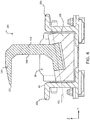
FIG. 4 illustrates a cross-sectional view of a restraint assembly, in a raised position, installed in a tray of a cargo system, in accordance with various embodiments; -
FIGS. 5A and 5B illustrate views of a restraint assembly having a rotatable vertical restraint, in accordance with various embodiments; and -
FIG. 6 is a schematic flow chart diagram of a method for guiding and/or restraining cargo, in accordance with various embodiments. - The subject matter of the present disclosure is particularly pointed out and distinctly claimed in the concluding portion of the specification. A more complete understanding of the present disclosure, however, may best be obtained by referring to the detailed description and claims when considered in connection with the drawing figures.
- The detailed description of exemplary embodiments herein makes reference to the accompanying drawings, which show exemplary embodiments by way of illustration. While these exemplary embodiments are described in sufficient detail to enable those skilled in the art to practice the disclosure, it should be understood that other embodiments may be realized and that logical changes and adaptations in design and construction may be made in accordance with this disclosure and the teachings herein without departing from the spirit and scope of the disclosure. Thus, the detailed description herein is presented for purposes of illustration only and not of limitation.
- As used herein, "aft" refers to the direction associated with the tail of an aircraft, or generally, to the direction of exhaust of the gas turbine. As used herein, "forward" refers to the direction associated with the nose of an aircraft, or generally, to the direction of flight or motion.
- Cargo management systems, as disclosed herein, are used to load, move, and unload cargo. While numerous examples and details are included below with reference to aircraft cargo systems, it is expected that the present disclosure may apply to other, non-aircraft type cargo systems.
- With reference to
FIG. 1 , anaircraft 10 is illustrated having acargo compartment 12. Acargo door 14 provides access tocargo compartment 12 fromoutside aircraft 10. Cargo 16 (e.g., pallets, ULDs, luggage, etc.) may be loaded and unloaded throughcargo door 14 and onto acargo deck 18 ofaircraft 10. In various embodiments,cargo deck 18 of the cargo system may be equipped with one or more power drive units (PDUs) configured to propelcargo 16 acrosscargo deck 18 in a desired direction. - With reference to
FIG. 2 , a portion ofcargo deck 18 is illustrated in greater detail.Cargo deck 18 may include one ormore ball mats 20 and one ormore trays 22.Ball mats 20 may include a plurality of freely rotatingconveyance balls 24 andtrays 22 may include a plurality of freely rotatingconveyance rollers 26. In various embodiments, a number ofPDUs 28 may be mounted alongcargo deck 18. For example,PDUs 28 may be located inball mats 20 and/or inroller trays 22.PDUs 28 may be configured to propel cargo overconveyance balls 24 and/orconveyance rollers 26 and acrosscargo deck 18. In accordance with various embodiments, a number ofrestraint assemblies 100 may be located alongcargo deck 18. Therestraint assemblies 100 generally provide longitudinal guidance and/or restraint to cargo items, such as ULDs. Accordingly, the term "restraint assembly" refers generally to an apparatus, device, or system that provides guidance and/or restraint to cargo. That is, the embodiments of therestraint assemblies 100/200 provided herein may be configured to provide guidance to cargo as it moves along the cargo system, to restrain and retain cargo once it is in a desired position, or to provide both guidance and restraint to cargo. Therestraint assemblies 100 may be mounted to thetrays 22, or could otherwise be implemented and/or mounted relative to a panel, a hogout, or other structure of a cargo system. For example,restraint assemblies 100 may be installed between afirst rail 30a and asecond rail 30b oftray 22.Second rail 30b may be parallel tofirst rail 30a. As described in greater detail below, therestraint assemblies 100 can be in a stored position when not needed, and can be transitioned to a raised position when cargo guidance/restraint is desired. In various embodiments, thetrays 22 are coupled/mounted to an airframe of the aircraft. - In the stored position, the
restraint assemblies 100 are disposed below/beneath the conveyance plane, which is defined as the plane tangent to the top of the conveyance rollers. For example, therestraint assemblies 100 may be disposed below/beneath the conveyance plane (e.g., in avolume 80 defined between first andsecond rails restraint assemblies 100 are disposed above the conveyance plane (e.g., above thevolume 80 defined between first andsecond rails more restraint assemblies 100 provide longitudinal guidance, lateral restraint, and vertical restraint. As used herein, the term "longitudinal" refers to directions along the x-axis, the term "lateral" refers to directions along the y-axis, and the term "vertical" refers to directions along the z-axis. Therestraint assemblies 100 may be held or biased in either the stored or raised position (e.g., spring-loaded or latched). Therestraint assemblies 100 may be controlled using actuators (e.g., motor driven actuators) and therestraint assemblies 100 may be reversibly locked into either position. Therestraint assembly 100 may include a controller and a motor. In various embodiments, therestraint assembly 100 may be in mechanical communication with the restraint motor, which may be, for example, an electromagnetic, electromechanical or electrohydraulic actuator or other servomechanism. In various embodiments, the controller is configured to control operation of therestraint assembly 100. The restraint controller may include a processor and a tangible, non-transitory memory. The processor may comprise one or more logic modules that implement logic to control operation of the restraint assembly (e.g., switching between the stored and the raised positions. - In various embodiments, a human operator manipulates control elements to selectively and mechanically or electrically actuate the
restraint assemblies 100. For example, the arestraint assembly 100 may be actuated by a lever, a latch, or other mechanical features disposed in proximity to the restraint assembly 100 (e.g., hand or foot operable). The user/control interface may be mounted on a wall or other structure within the cargo bay or may be portable, e.g., the controls may be in a hand held device. In various embodiments, the cargo system may include one or more cargo shuttles that are configured to slide across floor panels or roll across theconveyance rollers 26. In various embodiments, the system controller may include a general purpose processor, a digital signal processor (DSP), an application specific integrated circuit (ASIC), a field programmable gate array (FPGA) or some other programmable logic device, discrete gate or transistor logic, discrete hardware components, or any combination thereof. The cargo handling system may also include a power source configured to supply power to therestraint assemblies 100 via one or more power busses. - With reference to
FIG. 3A ,3B , and4 , therestraint assembly 100 generally includes abase 105, alateral restraint 110, and avertical restraint 120. The term "lateral restraint" 110 refers generally to the portion of therestraint assembly 100 that provides lateral restraint and/or longitudinal guidance to the cargo (i.e., the modifier "lateral" does not refer to the orientation or extension direction of the restraint). That is, thelateral restraint 110 may provide guidance to cargo as it moves along the cargo system, may retain or restrain cargo once it is in a desired position, or may provide both guidance and restraint to cargo. The term "vertical restraint" refers generally to the portion of therestraint assembly 100 that provides vertical restraint (i.e., the modifier "vertical" does not refer to the orientation or extension direction of the restraint). InFIGS. 3A and4 , therestraint assembly 100 is shown in a raised position (e.g., deployed position). Thelateral restraint 110 includes aguide face 115 configured to engage lateral sides of cargo, such as ULDs, to provide longitudinal guidance while conveying the cargo and/or to provide lateral restraint to the cargo. - In various embodiments, and with reference to
FIGS. 3A ,3B , and4 , thebase 105 is mounted to the tray between therails lateral restraint 110 is rotatably coupled (e.g., via a first rotational axis 101) to thebase 105. The firstrotational axis 101 may be perpendicular to the longitudinal axis of the tray (e.g., may be perpendicular to the direction in which cargo is configured to be conveyed along the trays). As shown inFIG. 4 , the firstrotational axis 101 may be oblique relative to a conveyance plane of the cargo system. That is, the firstrotational axis 101 may extend perpendicular to the longitudinal axis of the tray but at an angle relative to the y-axis. In various embodiments, the firstrotational axis 101 may also be skewed into or out of the page. Accordingly, the first rotational axis may be tilted/skewed relative to the standard xyz axes. By orienting the first rotational axis in this tilted manner, afront edge 121 of thevertical restraint 120 may at least partially overlap therail 30b in the raised position while also being stowable in the stored position within the cavity/volume 80 defined by the tray. That is, if the firstrotational axis 101 were not tilted in this manner and if at least thefront edge 121 of thevertical restraint 120 extended over atop surface 81 of therail 30b in the raised position, therestraint assembly 100 would collide with therail 30b upon trying to rotate the restraint down to the stored position. In various embodiments, and with reference toFIG. 3B , therestraint assembly 100 is shown in the stored position, with both thelateral restraint 110 and thevertical restraint 120 disposed within a volume defined by the tray (i.e., within avolume 80 defined between the tworails restraint assembly 100 may be configured to provide more than 90 degrees of rotational movement of the lateral restraint to ensure thelateral restraint 110 is sufficiently below the conveyance plane. In various embodiments, thevertical restraint 120 is unitary with and integrally extends from thelateral restraint 110. - In various embodiments, and with reference to
FIGS. 5A and 5B , thevertical restraint 220 is rotatably coupled to thelateral restraint 210 via a secondrotational axis 202. The secondrotational axis 202 may be parallel to the longitudinal axis of the tray (e.g., may be parallel to the direction in which cargo is configured to be conveyed along the trays). In various embodiments, this coupling between thelateral restraint 210 and thevertical restraint 220 is along atop edge 212 of the lateral restraint 210 (e.g., a top edge of the guide face 215). Because of the rotational coupling between thelateral restraint 210 and thevertical restraint 220, thevertical restraint 220 can be rotated to provide vertical restraining force to cargo. The secondrotational axis 202 may be perpendicular to the firstrotational axis 201. - In various embodiments, and with continued reference to
FIGS. 5A and 5B , therestraint assembly 200 may include alink 230. Thelink 230 may extend between thelateral restraint 210 and the tray (e.g.,rail 30a) of the cargo system to reversibly lock therestraint assembly 200 in the raised position. In various embodiments,restraints lateral restraint 210 and thevertical restraint 220 may transition between the stored and raised positions together. That is, actuation of thelateral restraint 210 may automatically trigger actuation of the vertical restraint 220 (or vice-versa). - In various embodiments, and with reference to
FIG. 6 , amethod 690 for guiding and/or restraining cargo is provided. Themethod 690 may include rotating a lateral restraint of a restraint assembly, relative to a tray of a cargo system, from a stored position to a raised position atstep 692. The method may also include rotating a vertical restraint of the restraint assembly, relative to the lateral restraint, from the stored position to the raised position atstep 694. In the stored position the lateral restraint and vertical restraint are disposed within a volume defined by the tray of the cargo system and in the raised position the vertical restraint and at least a guide face of the lateral restraint are disposed above the volume. In various embodiments,step 692 is performed about a first rotational axis,step 694 is performed about a second rotational axis, and the first rotational axis and the second rotational axis are perpendicular to each other. - Benefits, other advantages, and solutions to problems have been described herein with regard to specific embodiments. Furthermore, the connecting lines shown in the various figures contained herein are intended to represent exemplary functional relationships and/or physical couplings between the various elements. It should be noted that many alternative or additional functional relationships or physical connections may be present in a practical system. However, the benefits, advantages, solutions to problems, and any elements that may cause any benefit, advantage, or solution to occur or become more pronounced are not to be construed as critical, required, or essential features or elements of the disclosure.
- The scope of the disclosure is accordingly to be limited by nothing other than the appended claims, in which reference to an element in the singular is not intended to mean "one and only one" unless explicitly so stated, but rather "one or more." It is to be understood that unless specifically stated otherwise, references to "a," "an," and/or "the" may include one or more than one and that reference to an item in the singular may also include the item in the plural. All ranges and ratio limits disclosed herein may be combined.
- Moreover, where a phrase similar to "at least one of A, B, or C" is used in the claims, it is intended that the phrase be interpreted to mean that A alone may be present in an embodiment, B alone may be present in an embodiment, C alone may be present in an embodiment, or that any combination of the elements A, B and C may be present in a single embodiment; for example, A and B, A and C, B and C, or A and B and C. Different cross-hatching is used throughout the figures to denote different parts but not necessarily to denote the same or different materials.
- The steps recited in any of the method or process descriptions may be executed in any order and are not necessarily limited to the order presented. Furthermore, any reference to singular includes plural embodiments, and any reference to more than one component or step may include a singular embodiment or step. Elements and steps in the figures are illustrated for simplicity and clarity and have not necessarily been rendered according to any particular sequence. For example, steps that may be performed concurrently or in different order are illustrated in the figures to help to improve understanding of embodiments of the present disclosure.
- Any reference to attached, fixed, connected or the like may include permanent, removable, temporary, partial, full and/or any other possible attachment option. Additionally, any reference to without contact (or similar phrases) may also include reduced contact or minimal contact. Surface shading lines may be used throughout the figures to denote different parts or areas but not necessarily to denote the same or different materials. In some cases, reference coordinates may be specific to each figure.
- Systems, methods and apparatus are provided herein. In the detailed description herein, references to "one embodiment", "an embodiment", "various embodiments", etc., indicate that the embodiment described may include a particular feature, structure, or characteristic, but every embodiment may not necessarily include the particular feature, structure, or characteristic. Moreover, such phrases are not necessarily referring to the same embodiment. Further, when a particular feature, structure, or characteristic is described in connection with an embodiment, it is submitted that it is within the knowledge of one skilled in the art to affect such feature, structure, or characteristic in connection with other embodiments whether or not explicitly described. After reading the description, it will be apparent to one skilled in the relevant art(s) how to implement the disclosure in alternative embodiments.
- Furthermore, no element, component, or method step in the present disclosure is intended to be dedicated to the public regardless of whether the element, component, or method step is explicitly recited in the claims. No claim element is intended to invoke 35 U.S.C. 112(f) unless the element is expressly recited using the phrase "means for." As used herein, the terms "comprises", "comprising", or any other variation thereof, are intended to cover a non-exclusive inclusion, such that a process, method, article, or apparatus that comprises a list of elements does not include only those elements but may include other elements not expressly listed or inherent to such process, method, article, or apparatus.
Claims (15)
- A restraint assembly of a cargo system, the restraint assembly comprising:a base (105) configured to be mounted to a tray of the cargo system;a lateral restraint (110) comprising a guide face and a top edge, wherein the lateral restraint is rotatably coupled to the base; anda vertical restraint (120) extending from the top edge of the lateral restraint;wherein:the restraint assembly (100) is configured to have a stored position and a raised position;in the stored position both the lateral restraint and the vertical restraint are configured to be disposed within a volume defined by the tray of the cargo system; andin the raised position the vertical restraint and at least the guide face of the lateral restraint are configured to be disposed above the volume defined by the tray of the cargo system such that the restraint assembly provides at least one of longitudinal guidance, lateral restraining, and vertical restraining to cargo.
- The restraint assembly of claim 1, wherein a first rotational axis between the lateral restraint and the base is configured to extend perpendicular to a longitudinal axis of the tray of the cargo system.
- The restraint assembly of claim 2, wherein the first rotational axis between the lateral restraint and the base is configured to be oblique relative to a conveyance plane of the cargo system, and optionally wherein a front edge of the vertical restraint, in the raised position, is configured to extend at least partially over a top surface of a rail of the tray of the cargo system.
- The restraint assembly of claim 2, wherein the vertical restraint is rotatably coupled to the top edge of the lateral restraint.
- The restraint assembly of claim 4, wherein a second rotational axis between the vertical restraint and the lateral restraint is perpendicular to the first rotational axis, or wherein a second rotational axis between the vertical restraint and the lateral restraint is parallel to the longitudinal axis of the tray of the cargo system.
- The restraint assembly of claim 2, wherein the restraint assembly further comprises a link configured to extend between the lateral restraint and the tray of the cargo system to reversibly lock the restraint assembly in the raised position.
- The restraint assembly of any preceding claim, wherein the vertical restraint is unitary with and integrally extends from the lateral restraint, and/or wherein toggling between the stored position and the raised position comprises rotating the lateral restraint more than 90 degrees.
- A cargo system comprising:a tray defining a volume within which a roller is housed, wherein the roller is configured to facilitate movement of cargo along a longitudinal axis of the tray; anda restraint assembly comprising a base (105) mounted to the tray, a lateral restraint 8110) rotatably coupled to the base, and a vertical restraint (120) extending from the lateral restraint, the restraint assembly comprising a stored position and a raised position, wherein in the stored position the lateral restraint of the restraint assembly (100) is disposed within the volume defined by the tray and in the raised position the lateral restraint of the restraint assembly is disposed above the volume defined by the tray of the cargo system such that the restraint assembly provides at least one of longitudinal guidance, lateral restraining, and vertical restraining to cargo.
- The cargo system claim 8, wherein a first rotational axis between the lateral restraint and the base extends perpendicular to the longitudinal axis of the tray of the cargo system.
- The cargo system of claim 9, wherein the first rotational axis between the lateral restraint and the base is oblique relative to a conveyance plane of the cargo system, and optionally wherein a front edge of the vertical restraint, in the raised position, is configured to extend at least partially over a top surface of a rail of the tray of the cargo system.
- The cargo system of claim 9, wherein:the lateral restraint comprises a guide face and a top edge; andthe vertical restraint extends from the top edge of the lateral restraint.
- The cargo system of claim 11, wherein the vertical restraint is rotatably coupled to the top edge of the lateral restraint.
- The cargo system of claim 12, wherein a second rotational axis between the vertical restraint and the lateral restraint is perpendicular to the first rotational axis, or wherein a second rotational axis between the vertical restraint and the lateral restraint is parallel to the longitudinal axis of the tray of the cargo system.
- A method for guiding or restraining cargo, the method comprising:rotating a lateral restraint (110) of a restraint assembly (100), relative to a tray of a cargo system, from a stored position to a raised position; androtating a vertical restraint (120) of the restraint assembly, relative to the lateral restraint, from the stored position to the raised position;wherein in the stored position the lateral restraint and the vertical restraint are disposed within a volume defined by the tray of the cargo system and in the raised position the vertical restraint and at least a guide face of the lateral restraint are disposed above the volume.
- The method of claim 14, wherein:rotating the lateral restraint comprises rotating the lateral restraint, relative to a base mounted to the tray of the cargo system, about a first rotational axis;rotating the vertical restraint comprises rotating the vertical restraint, relative to the lateral restraint, about a second rotational axis; andthe first rotational axis is perpendicular to the second rotational axis.
Applications Claiming Priority (1)
| Application Number | Priority Date | Filing Date | Title |
|---|---|---|---|
| US16/539,224 US10919630B1 (en) | 2019-08-13 | 2019-08-13 | Restraint assembly for cargo system |
Publications (2)
| Publication Number | Publication Date |
|---|---|
| EP3778394A1 true EP3778394A1 (en) | 2021-02-17 |
| EP3778394B1 EP3778394B1 (en) | 2025-06-18 |
Family
ID=68771537
Family Applications (1)
| Application Number | Title | Priority Date | Filing Date |
|---|---|---|---|
| EP19213585.3A Active EP3778394B1 (en) | 2019-08-13 | 2019-12-04 | Restraint assembly for cargo system |
Country Status (2)
| Country | Link |
|---|---|
| US (1) | US10919630B1 (en) |
| EP (1) | EP3778394B1 (en) |
Families Citing this family (2)
| Publication number | Priority date | Publication date | Assignee | Title |
|---|---|---|---|---|
| EP4594184A1 (en) | 2022-09-30 | 2025-08-06 | Textron Systems Corporation | Roller-and-rail cargo handling system with pallet-moving trolley |
| US20250026477A1 (en) * | 2023-07-21 | 2025-01-23 | Goodrich Corporation | Compact vertically actuated anti-rollout restraint for use in internal cargo restraint system |
Citations (3)
| Publication number | Priority date | Publication date | Assignee | Title |
|---|---|---|---|---|
| US3759476A (en) * | 1972-02-18 | 1973-09-18 | Mc Donnell Douglas Corp | Latching system |
| WO2004054876A1 (en) * | 2002-12-13 | 2004-07-01 | Pfalz-Flugzeugwerke Gmbh | Locking device for freight loading systems |
| EP3508422A1 (en) * | 2018-01-09 | 2019-07-10 | Goodrich Corporation | Tray mounted longitudinal guide with conveyance in the lowered position and vertical restraint in the raised position |
Family Cites Families (56)
| Publication number | Priority date | Publication date | Assignee | Title |
|---|---|---|---|---|
| US3377040A (en) * | 1966-12-05 | 1968-04-09 | Boeing Co | Retractable cargo securing device |
| US3693920A (en) * | 1970-12-09 | 1972-09-26 | Boeing Co | Retractable cargo securing device |
| DE2432245B2 (en) | 1974-07-05 | 1976-07-01 | Messerschmitt-Bölkow-Blohm GmbH, 8000 München | ROLLABLE DEVICE FOR LOCKING CARRIERS |
| FR2331507A1 (en) * | 1975-11-17 | 1977-06-10 | Pelletier Expl Ets H | LOCK FOR LOCKING PALLETIZED OR CONTAINER FREIGHT IN A VEHICLE |
| US4049286A (en) | 1976-01-12 | 1977-09-20 | Saginaw Products Corporation | Latch assembly for containerized baggage trailer |
| US4077590A (en) | 1976-03-11 | 1978-03-07 | The Boeing Company | Integrated treadway cargo handling system |
| US4144821A (en) * | 1977-04-13 | 1979-03-20 | Lang Robert D | Aircraft cargo pallet restraint |
| US4331412A (en) | 1979-11-23 | 1982-05-25 | Brooks & Perkins, Incorporated | Retractable pallet securing device |
| AU6712381A (en) | 1980-02-13 | 1981-08-20 | Visser, K. | Device for loading goods |
| US4395172A (en) | 1980-12-12 | 1983-07-26 | The Boeing Company | Cargo restraint system with spring fuse |
| DE3107745C2 (en) | 1981-02-28 | 1987-03-19 | Messerschmitt-Bölkow-Blohm GmbH, 8012 Ottobrunn | Locking element for locking cargo items |
| US4867622A (en) | 1988-07-21 | 1989-09-19 | Bethlehem Steel Corporation | Lateral restraining device for cargo containers having more than one width |
| US5000635A (en) | 1989-11-17 | 1991-03-19 | The Boeing Company | Spring-loaded outboard side lock |
| US5131606A (en) | 1991-04-01 | 1992-07-21 | Arnold Nordstrom | Seat pallet and cargo pallet restraining system |
| DE4210702C2 (en) | 1992-04-01 | 1995-09-21 | Daimler Benz Aerospace Airbus | Device for guiding |
| US5265991A (en) * | 1992-10-30 | 1993-11-30 | Aar Corp. | Retractable cargo restraint and cargo restraining system |
| DE4309683C2 (en) * | 1993-03-25 | 1995-11-09 | Talbot Waggonfab | Fixing device for swap bodies and / or containers |
| US5564654A (en) * | 1994-10-13 | 1996-10-15 | Nordstrom; Arnold | Aircraft cargo restraint apparatus |
| US5573359A (en) * | 1995-05-08 | 1996-11-12 | Ancra International Corporation | Cargo securing device |
| DE59807512D1 (en) | 1997-05-28 | 2003-04-24 | Telair Int Gmbh | Installation device for a roller drive unit |
| US6193453B1 (en) | 1997-07-24 | 2001-02-27 | Willem J. A. Kernkamp | Cargo lock for fixing cargo pallets to seat tracks in aircraft |
| US5957406A (en) | 1997-12-03 | 1999-09-28 | The Boeing Company | Bi-directional cargo restraint |
| DE19816892C2 (en) * | 1998-04-16 | 2000-05-18 | Telair Int Gmbh | bars |
| US6425717B1 (en) | 2000-11-08 | 2002-07-30 | The Boeing Company | Cargo restraint device |
| US6485238B2 (en) | 2001-03-16 | 2002-11-26 | Pemco Aviation Group | Restraint apparatus |
| US6557800B2 (en) | 2001-09-26 | 2003-05-06 | The Boeing Company | Cargo handling system for aircraft compartments |
| DE10205871B4 (en) | 2002-02-13 | 2006-05-04 | Telair International Gmbh | Mounting device for a functional element |
| US6729818B1 (en) * | 2003-01-14 | 2004-05-04 | The Boeing Company | Supplemental cargo restraint system for oversized cargo |
| US20040265085A1 (en) | 2003-06-27 | 2004-12-30 | Mayer Henry P. | Cargo restraint device |
| US7086517B2 (en) | 2004-10-29 | 2006-08-08 | The Boeing Company | Cargo system roller/lock/power drive unit tray integration |
| DE102005017425B4 (en) | 2005-04-15 | 2010-08-19 | Airbus Deutschland Gmbh | Loading aids for cargo holds in aircraft |
| US7429157B2 (en) | 2005-10-13 | 2008-09-30 | Goodrich Corporation | Overrideable guide and vertical restraint for an air cargo system |
| GB2440062B (en) * | 2005-10-13 | 2008-03-12 | Goodrich Corp | Overridable guide and verticle restraint for an air cargo system |
| US7435043B2 (en) * | 2005-10-14 | 2008-10-14 | Goodrich Corporation | Air cargo vertical restraint assembly |
| US7665938B2 (en) | 2006-03-30 | 2010-02-23 | Goodrich Corporation | Coaxially mounted retracting guide and restraint for an air cargo system |
| US7731460B2 (en) | 2006-10-30 | 2010-06-08 | Goodrich Corporation | Self-adjusting ULD loading guide and restraint |
| FR2916422B1 (en) | 2007-05-25 | 2016-09-30 | Goodrich Corp | METHOD FOR MODIFYING THE CARGO AIRBAR FOR RECEIVING STANDARD PALLETS OF DIFFERENT LENGTHS, KIT OF IMPLEMENTATION AND PLANE SO EQUIPPED |
| US20080310944A1 (en) | 2007-06-14 | 2008-12-18 | Goodrich Corporation | Power drive unit with eccentric roller lift system |
| US7854579B2 (en) | 2007-07-13 | 2010-12-21 | Goodrich Corporation | Air cargo rollout stop |
| US7530774B2 (en) | 2007-07-13 | 2009-05-12 | Goodrich Corporation | Air cargo rollout stop |
| WO2009061347A1 (en) | 2007-10-17 | 2009-05-14 | Woodland Richard L K | Aircraft based non-dedicated special mission pod mounting apparatus |
| US8038373B2 (en) | 2008-12-05 | 2011-10-18 | Drs Training & Control Systems, Llc | Folding pallet latch with integral rollout prevention |
| US7988391B2 (en) | 2009-02-17 | 2011-08-02 | Goodrich Corporation | Self-locking, overrideable and attenuating cargo guide and restraint |
| DE102009012427B4 (en) | 2009-03-10 | 2015-08-27 | Telair International Gmbh | roller conveyor |
| US8690103B2 (en) * | 2010-01-19 | 2014-04-08 | Goodrich Corporation | Method and apparatus for converting aircraft from commercial to military freight service |
| DE102010036983B4 (en) | 2010-08-13 | 2012-05-03 | Telair International Gmbh | Side guide, side guide group, cargo deck |
| DE102010035099A1 (en) | 2010-08-23 | 2012-02-23 | Airbus Operations Gmbh | Fully automatic freight loading system |
| US8585334B2 (en) | 2012-04-03 | 2013-11-19 | Ancra International Llc | Attenuating cargo restraint device |
| US20160001870A1 (en) | 2014-07-07 | 2016-01-07 | Ancra International Llc | Method for loading cargo into an aircraft |
| BR102016000552B1 (en) | 2016-01-11 | 2022-12-27 | Embraer S.A | LONGITUDINAL LOCKING DEVICE FOR LOADING IN AIRCRAFT |
| US10118700B2 (en) | 2016-10-12 | 2018-11-06 | Goodrich Corporation | SMA actuated restraint assembly |
| EP3326913B1 (en) | 2016-11-24 | 2020-02-05 | Airbus Defence and Space, S.A.U. | Anti-rattling device for pallets in cargo aircraft |
| US9932113B1 (en) | 2016-12-02 | 2018-04-03 | Goodrich Corporation | Restraint assembly for cargo system |
| US10450066B2 (en) | 2017-02-09 | 2019-10-22 | Goodrich Corporation | Lock assembly with rotating inner pawl |
| US10392111B2 (en) | 2017-03-23 | 2019-08-27 | Goodrich Corporation | Semi-automated lock assembly |
| US10577106B2 (en) | 2017-08-31 | 2020-03-03 | The Boeing Company | System and method for restraining cargo |
-
2019
- 2019-08-13 US US16/539,224 patent/US10919630B1/en active Active
- 2019-12-04 EP EP19213585.3A patent/EP3778394B1/en active Active
Patent Citations (3)
| Publication number | Priority date | Publication date | Assignee | Title |
|---|---|---|---|---|
| US3759476A (en) * | 1972-02-18 | 1973-09-18 | Mc Donnell Douglas Corp | Latching system |
| WO2004054876A1 (en) * | 2002-12-13 | 2004-07-01 | Pfalz-Flugzeugwerke Gmbh | Locking device for freight loading systems |
| EP3508422A1 (en) * | 2018-01-09 | 2019-07-10 | Goodrich Corporation | Tray mounted longitudinal guide with conveyance in the lowered position and vertical restraint in the raised position |
Also Published As
| Publication number | Publication date |
|---|---|
| US10919630B1 (en) | 2021-02-16 |
| EP3778394B1 (en) | 2025-06-18 |
| US20210047040A1 (en) | 2021-02-18 |
Similar Documents
| Publication | Publication Date | Title |
|---|---|---|
| US10919433B1 (en) | Restraint assembly for cargo system | |
| US12195197B2 (en) | Cargo handling systems and methods | |
| US4050655A (en) | Cargo loading method and apparatus | |
| US6557800B2 (en) | Cargo handling system for aircraft compartments | |
| US8864079B2 (en) | Aircraft cargo compartment container crane system | |
| EP2441668B1 (en) | Low profile cargo handling system | |
| US11505319B2 (en) | Restraint assembly for cargo system | |
| US9340286B2 (en) | Automatic transport device for cargo loading system | |
| EP3650344B1 (en) | System and method for verifying latch engagement for cargo handling systems | |
| US10919630B1 (en) | Restraint assembly for cargo system | |
| US20240400241A1 (en) | Deployment system for unmanned aerial vehicles | |
| EP3778302B1 (en) | Stowable cargo guide for cargo roller trays | |
| US10577109B2 (en) | System and method for deplaning and boarding airplanes | |
| EP4603385A1 (en) | Pallet skew correction | |
| US12090097B2 (en) | Platform system for securing a wheelchair in position within an internal cabin of a vehicle | |
| US20230150671A1 (en) | Toggle lock restraint for aircraft cargo handling systems | |
| CN115520393A (en) | Material delivery system and method based on unmanned aerial vehicle | |
| US12384540B2 (en) | Cargo handling system repositionable side guide | |
| CN116022334A (en) | Aircraft packing box throwing device and aircraft | |
| US20260109543A1 (en) | Attenuated braking roller | |
| GB2500767A (en) | System for loading passengers into a vehicle |
Legal Events
| Date | Code | Title | Description |
|---|---|---|---|
| PUAI | Public reference made under article 153(3) epc to a published international application that has entered the european phase |
Free format text: ORIGINAL CODE: 0009012 |
|
| STAA | Information on the status of an ep patent application or granted ep patent |
Free format text: STATUS: THE APPLICATION HAS BEEN PUBLISHED |
|
| AK | Designated contracting states |
Kind code of ref document: A1 Designated state(s): AL AT BE BG CH CY CZ DE DK EE ES FI FR GB GR HR HU IE IS IT LI LT LU LV MC MK MT NL NO PL PT RO RS SE SI SK SM TR |
|
| AX | Request for extension of the european patent |
Extension state: BA ME |
|
| STAA | Information on the status of an ep patent application or granted ep patent |
Free format text: STATUS: REQUEST FOR EXAMINATION WAS MADE |
|
| 17P | Request for examination filed |
Effective date: 20210813 |
|
| RBV | Designated contracting states (corrected) |
Designated state(s): AL AT BE BG CH CY CZ DE DK EE ES FI FR GB GR HR HU IE IS IT LI LT LU LV MC MK MT NL NO PL PT RO RS SE SI SK SM TR |
|
| STAA | Information on the status of an ep patent application or granted ep patent |
Free format text: STATUS: EXAMINATION IS IN PROGRESS |
|
| 17Q | First examination report despatched |
Effective date: 20220808 |
|
| P01 | Opt-out of the competence of the unified patent court (upc) registered |
Effective date: 20230922 |
|
| GRAP | Despatch of communication of intention to grant a patent |
Free format text: ORIGINAL CODE: EPIDOSNIGR1 |
|
| STAA | Information on the status of an ep patent application or granted ep patent |
Free format text: STATUS: GRANT OF PATENT IS INTENDED |
|
| INTG | Intention to grant announced |
Effective date: 20250107 |
|
| GRAS | Grant fee paid |
Free format text: ORIGINAL CODE: EPIDOSNIGR3 |
|
| GRAA | (expected) grant |
Free format text: ORIGINAL CODE: 0009210 |
|
| STAA | Information on the status of an ep patent application or granted ep patent |
Free format text: STATUS: THE PATENT HAS BEEN GRANTED |
|
| AK | Designated contracting states |
Kind code of ref document: B1 Designated state(s): AL AT BE BG CH CY CZ DE DK EE ES FI FR GB GR HR HU IE IS IT LI LT LU LV MC MK MT NL NO PL PT RO RS SE SI SK SM TR |
|
| REG | Reference to a national code |
Ref country code: GB Ref legal event code: FG4D |
|
| REG | Reference to a national code |
Ref country code: CH Ref legal event code: EP |
|
| REG | Reference to a national code |
Ref country code: DE Ref legal event code: R096 Ref document number: 602019071195 Country of ref document: DE |
|
| REG | Reference to a national code |
Ref country code: CH Ref legal event code: EP |
|
| REG | Reference to a national code |
Ref country code: IE Ref legal event code: FG4D |
|
| PG25 | Lapsed in a contracting state [announced via postgrant information from national office to epo] |
Ref country code: FI Free format text: LAPSE BECAUSE OF FAILURE TO SUBMIT A TRANSLATION OF THE DESCRIPTION OR TO PAY THE FEE WITHIN THE PRESCRIBED TIME-LIMIT Effective date: 20250618 |
|
| REG | Reference to a national code |
Ref country code: LT Ref legal event code: MG9D |
|
| PG25 | Lapsed in a contracting state [announced via postgrant information from national office to epo] |
Ref country code: NO Free format text: LAPSE BECAUSE OF FAILURE TO SUBMIT A TRANSLATION OF THE DESCRIPTION OR TO PAY THE FEE WITHIN THE PRESCRIBED TIME-LIMIT Effective date: 20250918 Ref country code: GR Free format text: LAPSE BECAUSE OF FAILURE TO SUBMIT A TRANSLATION OF THE DESCRIPTION OR TO PAY THE FEE WITHIN THE PRESCRIBED TIME-LIMIT Effective date: 20250919 |
|
| PG25 | Lapsed in a contracting state [announced via postgrant information from national office to epo] |
Ref country code: BG Free format text: LAPSE BECAUSE OF FAILURE TO SUBMIT A TRANSLATION OF THE DESCRIPTION OR TO PAY THE FEE WITHIN THE PRESCRIBED TIME-LIMIT Effective date: 20250618 |
|
| PG25 | Lapsed in a contracting state [announced via postgrant information from national office to epo] |
Ref country code: HR Free format text: LAPSE BECAUSE OF FAILURE TO SUBMIT A TRANSLATION OF THE DESCRIPTION OR TO PAY THE FEE WITHIN THE PRESCRIBED TIME-LIMIT Effective date: 20250618 |
|
| PG25 | Lapsed in a contracting state [announced via postgrant information from national office to epo] |
Ref country code: RS Free format text: LAPSE BECAUSE OF FAILURE TO SUBMIT A TRANSLATION OF THE DESCRIPTION OR TO PAY THE FEE WITHIN THE PRESCRIBED TIME-LIMIT Effective date: 20250918 |
|
| REG | Reference to a national code |
Ref country code: NL Ref legal event code: MP Effective date: 20250618 |
|
| PG25 | Lapsed in a contracting state [announced via postgrant information from national office to epo] |
Ref country code: LV Free format text: LAPSE BECAUSE OF FAILURE TO SUBMIT A TRANSLATION OF THE DESCRIPTION OR TO PAY THE FEE WITHIN THE PRESCRIBED TIME-LIMIT Effective date: 20250618 |
|
| PG25 | Lapsed in a contracting state [announced via postgrant information from national office to epo] |
Ref country code: NL Free format text: LAPSE BECAUSE OF FAILURE TO SUBMIT A TRANSLATION OF THE DESCRIPTION OR TO PAY THE FEE WITHIN THE PRESCRIBED TIME-LIMIT Effective date: 20250618 |
|
| PG25 | Lapsed in a contracting state [announced via postgrant information from national office to epo] |
Ref country code: PT Free format text: LAPSE BECAUSE OF FAILURE TO SUBMIT A TRANSLATION OF THE DESCRIPTION OR TO PAY THE FEE WITHIN THE PRESCRIBED TIME-LIMIT Effective date: 20251020 |
|
| REG | Reference to a national code |
Ref country code: AT Ref legal event code: MK05 Ref document number: 1803987 Country of ref document: AT Kind code of ref document: T Effective date: 20250618 |
|
| PG25 | Lapsed in a contracting state [announced via postgrant information from national office to epo] |
Ref country code: IS Free format text: LAPSE BECAUSE OF FAILURE TO SUBMIT A TRANSLATION OF THE DESCRIPTION OR TO PAY THE FEE WITHIN THE PRESCRIBED TIME-LIMIT Effective date: 20251018 |
|
| PGFP | Annual fee paid to national office [announced via postgrant information from national office to epo] |
Ref country code: DE Payment date: 20251126 Year of fee payment: 7 |
|
| PG25 | Lapsed in a contracting state [announced via postgrant information from national office to epo] |
Ref country code: AT Free format text: LAPSE BECAUSE OF FAILURE TO SUBMIT A TRANSLATION OF THE DESCRIPTION OR TO PAY THE FEE WITHIN THE PRESCRIBED TIME-LIMIT Effective date: 20250618 Ref country code: SM Free format text: LAPSE BECAUSE OF FAILURE TO SUBMIT A TRANSLATION OF THE DESCRIPTION OR TO PAY THE FEE WITHIN THE PRESCRIBED TIME-LIMIT Effective date: 20250618 |
|
| PGFP | Annual fee paid to national office [announced via postgrant information from national office to epo] |
Ref country code: FR Payment date: 20251120 Year of fee payment: 7 |
|
| PG25 | Lapsed in a contracting state [announced via postgrant information from national office to epo] |
Ref country code: CZ Free format text: LAPSE BECAUSE OF FAILURE TO SUBMIT A TRANSLATION OF THE DESCRIPTION OR TO PAY THE FEE WITHIN THE PRESCRIBED TIME-LIMIT Effective date: 20250618 |
|
| PG25 | Lapsed in a contracting state [announced via postgrant information from national office to epo] |
Ref country code: PL Free format text: LAPSE BECAUSE OF FAILURE TO SUBMIT A TRANSLATION OF THE DESCRIPTION OR TO PAY THE FEE WITHIN THE PRESCRIBED TIME-LIMIT Effective date: 20250618 |
|
| PG25 | Lapsed in a contracting state [announced via postgrant information from national office to epo] |
Ref country code: EE Free format text: LAPSE BECAUSE OF FAILURE TO SUBMIT A TRANSLATION OF THE DESCRIPTION OR TO PAY THE FEE WITHIN THE PRESCRIBED TIME-LIMIT Effective date: 20250618 |
|
| PG25 | Lapsed in a contracting state [announced via postgrant information from national office to epo] |
Ref country code: RO Free format text: LAPSE BECAUSE OF FAILURE TO SUBMIT A TRANSLATION OF THE DESCRIPTION OR TO PAY THE FEE WITHIN THE PRESCRIBED TIME-LIMIT Effective date: 20250618 Ref country code: SK Free format text: LAPSE BECAUSE OF FAILURE TO SUBMIT A TRANSLATION OF THE DESCRIPTION OR TO PAY THE FEE WITHIN THE PRESCRIBED TIME-LIMIT Effective date: 20250618 |
|
| PG25 | Lapsed in a contracting state [announced via postgrant information from national office to epo] |
Ref country code: ES Free format text: LAPSE BECAUSE OF FAILURE TO SUBMIT A TRANSLATION OF THE DESCRIPTION OR TO PAY THE FEE WITHIN THE PRESCRIBED TIME-LIMIT Effective date: 20250618 |
|
| REG | Reference to a national code |
Ref country code: DE Ref legal event code: R097 Ref document number: 602019071195 Country of ref document: DE |
|
| PG25 | Lapsed in a contracting state [announced via postgrant information from national office to epo] |
Ref country code: DK Free format text: LAPSE BECAUSE OF FAILURE TO SUBMIT A TRANSLATION OF THE DESCRIPTION OR TO PAY THE FEE WITHIN THE PRESCRIBED TIME-LIMIT Effective date: 20250618 |
|
| PG25 | Lapsed in a contracting state [announced via postgrant information from national office to epo] |
Ref country code: IT Free format text: LAPSE BECAUSE OF FAILURE TO SUBMIT A TRANSLATION OF THE DESCRIPTION OR TO PAY THE FEE WITHIN THE PRESCRIBED TIME-LIMIT Effective date: 20250618 |
|
| PLBE | No opposition filed within time limit |
Free format text: ORIGINAL CODE: 0009261 |
|
| STAA | Information on the status of an ep patent application or granted ep patent |
Free format text: STATUS: NO OPPOSITION FILED WITHIN TIME LIMIT |
|
| REG | Reference to a national code |
Ref country code: CH Ref legal event code: L10 Free format text: ST27 STATUS EVENT CODE: U-0-0-L10-L00 (AS PROVIDED BY THE NATIONAL OFFICE) Effective date: 20260430 |