EP3778317A1 - Dynamic sweep angle measurement for fault monitoring of windshield wiper systems - Google Patents
Dynamic sweep angle measurement for fault monitoring of windshield wiper systems Download PDFInfo
- Publication number
- EP3778317A1 EP3778317A1 EP19212942.7A EP19212942A EP3778317A1 EP 3778317 A1 EP3778317 A1 EP 3778317A1 EP 19212942 A EP19212942 A EP 19212942A EP 3778317 A1 EP3778317 A1 EP 3778317A1
- Authority
- EP
- European Patent Office
- Prior art keywords
- sweep angle
- wiper
- blade assembly
- wiper blade
- controller
- Prior art date
- Legal status (The legal status is an assumption and is not a legal conclusion. Google has not performed a legal analysis and makes no representation as to the accuracy of the status listed.)
- Granted
Links
Images


Classifications
-
- B—PERFORMING OPERATIONS; TRANSPORTING
- B60—VEHICLES IN GENERAL
- B60S—SERVICING, CLEANING, REPAIRING, SUPPORTING, LIFTING, OR MANOEUVRING OF VEHICLES, NOT OTHERWISE PROVIDED FOR
- B60S1/00—Cleaning of vehicles
- B60S1/02—Cleaning windscreens, windows or optical devices
- B60S1/04—Wipers or the like, e.g. scrapers
- B60S1/32—Wipers or the like, e.g. scrapers characterised by constructional features of wiper blade arms or blades
- B60S1/34—Wiper arms; Mountings therefor
- B60S1/3402—Wiper arms; Mountings therefor with means for obtaining particular wiping patterns
- B60S1/3409—Wiper arms; Mountings therefor with means for obtaining particular wiping patterns the wiper arms consisting of two or more articulated elements
-
- B—PERFORMING OPERATIONS; TRANSPORTING
- B60—VEHICLES IN GENERAL
- B60S—SERVICING, CLEANING, REPAIRING, SUPPORTING, LIFTING, OR MANOEUVRING OF VEHICLES, NOT OTHERWISE PROVIDED FOR
- B60S1/00—Cleaning of vehicles
- B60S1/02—Cleaning windscreens, windows or optical devices
- B60S1/04—Wipers or the like, e.g. scrapers
- B60S1/06—Wipers or the like, e.g. scrapers characterised by the drive
- B60S1/08—Wipers or the like, e.g. scrapers characterised by the drive electrically driven
-
- B—PERFORMING OPERATIONS; TRANSPORTING
- B60—VEHICLES IN GENERAL
- B60S—SERVICING, CLEANING, REPAIRING, SUPPORTING, LIFTING, OR MANOEUVRING OF VEHICLES, NOT OTHERWISE PROVIDED FOR
- B60S1/00—Cleaning of vehicles
- B60S1/02—Cleaning windscreens, windows or optical devices
- B60S1/04—Wipers or the like, e.g. scrapers
- B60S1/06—Wipers or the like, e.g. scrapers characterised by the drive
- B60S1/16—Means for transmitting drive
- B60S1/18—Means for transmitting drive mechanically
- B60S1/26—Means for transmitting drive mechanically by toothed gearing
Definitions
- the following description relates to windshield wiper systems (WWSs) and, more specifically, to dynamic sweep angle measurement for fault monitoring of a WWS.
- WWSs windshield wiper systems
- a WWS is typically employed on a vehicle, such as an aircraft, to clear moisture or foreign object debris from a windshield and to allow for improved visibility.
- a WWS on an aircraft can be used to improve visibility for pilots or co-pilots during take-off or landing operations.
- the WWS will generally be designed to move through a specific wipe or sweep angle. This sweep angle can be controlled with or without a four bar mechanism designed to configured the WWS to sweep through the specific angle and return to a park position.
- the WWS is not typically expected to have any movement or flutter when it is non-operational under all loading conditions.
- a windshield wiper system includes a wiper blade assembly drivable along a first sweep angle, an internal wiper trigger disposed to move with the wiper blade assembly, a measurement system configured to monitor a position of the internal wiper trigger from which a corresponding position of the wiper blade assembly relative to the first sweep angle is measurable and to output a sweep angle feedback signal corresponding to monitoring results and a controller.
- the controller is receptive of the sweep angle feedback signal.
- the controller is configured to control a driving of the wiper blade assembly in accordance with the sweep angle feedback signal.
- the wiper blade assembly is configured to move across a windshield of a vehicle and includes a wiper arm and a wiper blade attached to the wiper arm.
- the WWS further includes a motor, which is operable by a motor drive control signal output from the controller, and a mechanical gear train and four bar linkage operably interposed between the motor and the wiper blade assembly.
- the controller is configured to control the driving of the wiper blade assembly in accordance with the sweep angle feedback signal and in accordance with position, current and temperature feedback signals derived from the motor.
- the internal wiper trigger is coupled to the wiper blade assembly.
- the internal wiper trigger generates a magnetic field and the measurement system is responsive to the magnetic field to monitor the position of the internal wiper trigger.
- the measurement system includes Hall Effect sensors positioned proximate to opposite ends of the second sweep angle and the Hall Effect sensors are configured to generate a variable duty cycle output responsive to the magnetic field and to issue the variable duty cycle output to the controller as the sweep angle feedback signal.
- a windshield wiper system includes a wiper blade assembly drivable along a first sweep angle, an internal wiper trigger disposed to move with the wiper blade assembly and along a second sweep angle corresponding to the first sweep angle, a measurement system configured to monitor a position of the internal wiper trigger relative to the second sweep angle from which a corresponding position of the wiper blade assembly relative to the first sweep angle is measurable and to output a sweep angle feedback signal corresponding to monitoring results and a controller.
- the controller is receptive of the sweep angle feedback signal.
- the controller is configured to control a driving of the wiper blade assembly in accordance with at least the sweep angle feedback signal.
- the wiper blade assembly is configured to move across a windshield of a vehicle and includes a wiper arm and a wiper blade attached to the wiper arm.
- _the second sweep angle is a same sweep angle as the first sweep angle.
- the WWS further includes a motor, which is operable by a motor drive control signal output from the controller, and a mechanical gear train and four bar linkage operably interposed between the motor and the wiper blade assembly.
- the controller is configured to control the driving of the wiper blade assembly in accordance with the sweep angle feedback signal and in accordance with position, current and temperature feedback signals derived from the motor.
- the internal wiper trigger is coupled to the wiper blade assembly.
- the internal wiper trigger generates a magnetic field and the measurement system is responsive to the magnetic field to monitor the position of the internal wiper trigger relative to the second sweep angle.
- the measurement system includes Hall Effect sensors positioned proximate to opposite ends of the second sweep angle and the Hall Effect sensors are configured to generate a variable duty cycle output responsive to the magnetic field and to issue the variable duty cycle output to the controller as the sweep angle feedback signal.
- a method of operating a windshield wiper system includes driving a wiper blade assembly along a first sweep angle by a controller, monitoring a position of an internal wiper trigger disposed to move with the wiper blade assembly from which a corresponding position of the wiper blade assembly relative to the first sweep angle is measurable, outputting a sweep angle feedback signal corresponding to results of the monitoring to the controller and controlling the driving of the wiper blade assembly by the controller in accordance with at least the sweep angle feedback signal.
- controlling of the driving of the wiper blade assembly by the controller is executed in accordance with the sweep angle feedback signal and in accordance with motor position, motor current and motor temperature feedback signals.
- the monitoring includes generating a magnetic field at an internal wiper trigger disposed to move with the wiper blade assembly and generating a variable duty cycle output responsive to the magnetic field for issuance to the controller as the sweep angle feedback signal.
- the sweep angle feedback signal has a negligible parallax error.
- the method further includes at least one of in-flight gear and shaft and real-time sweep angle monitoring based on the sweep angle feedback signal, computing a speed of a motor configured to drive the wiper blade assembly and facilitating an identification of ageing issues or failures of the motor, the wiper blade assembly or a gear train interposed between the motor and the wiper blade assembly.
- a conventional WWS can include an intelligent device with a controller or processor that provides a motor commutation sequence and monitors system faults, an internal wiper trigger that detects an end of sweep position of an external wiper blade, a park sensor feedback system with an end of sweep (EoS) sensor that detects the end of sweep position of the WWS by monitoring the internal wiper trigger, Hall sensor feedback to measure a speed of a motor of the WWS, motor current feedback to monitor motor winding currents, motor winding temperature feedback to monitor temperatures of the motor windings, a mechanical gear train and four bar link mechanism and a wiper arm and blade.
- the mechanical gear train and the four bar link mechanism converts rotary motion of the motor to oscillatory motion and the wiper arm and blade is driven by the oscillatory motion to wipe the windshield.
- Hall sensors are used to detect a speed of the motor. As such, any disconnections in Hall sensor signal lines can lead to system failures.
- the conventional WWS can include a worm gear that acts as a mechanical brake and a failure of the worm gear teeth can lead to an undesirable movement of the WWS from a park position.
- the conventional WWS does not have mechanism to detect this movement due to worm gear failure or other mechanical failures. That is, in the conventional WWS, Hall sensors are used for motor speed measurement but Hall sensors measure the speed only at motor ends and do not account for losses or faults in the mechanical gear train.
- a WWS is provided and configured with a capability of measuring a sweep angle of wiper blades by continuously monitoring a sweep angle of an internal wiper trigger.
- the continuous monitoring of the sweep angle is accomplished by way of strategically placed pulse width modulation (PWM) output linear Hall Effect sensors inside a wiper module.
- PWM pulse width modulation
- a conventional WWS can be characterized in that the internal wiper trigger is used only to detect an EoS of external wiper blades, the internal wiper trigger experiences same external loads as that of the external wiper blades and this internal wiper trigger can be leveraged for sweep angle measurement of the external wiper blades as both the internal wiper trigger and the external wiper blades have the same sweep angle.
- a windshield wiper system (WWS) 101 is provided for use with an airframe 110, such as an airframe of a vehicle or an aircraft.
- the airframe 110 is supportive of a windshield 111.
- the WWS 101 includes a wiper blade assembly 120 and an internal control assembly 130 (see FIG. 2 ).
- the wiper blade assembly 120 includes a wiper arm 121 and a wiper blade 122.
- the wiper blade 122 is attached to a distal end of the wiper arm 121 and is biased toward and onto the windshield 111 by the wiper arm 121.
- the wiper blade assembly 120 is configured to assume a parked position relative to the windshield 111 unless a pilot/copilot command is entered to initiate a driving of the wiper blade assembly 120 whereby the wiper blade 122 moves across the windshield 111 along a first sweep angle ⁇ 1.
- the internal control assembly 130 is configured to drive the wiper blade assembly 120 across the windshield 111 along the first sweep angle ⁇ 1 such that the wiper blade element moves across the windshield 111 to remove moisture or foreign object debris from the windshield 111.
- the WWS 101 further includes an internal wiper trigger 140 and a measurement system 150.
- the internal wiper trigger 140 is disposed to move with the wiper blade assembly 120 and along a second sweep angle ⁇ 2 (see FIG. 3 ) that corresponds to the first sweep angle ⁇ 1.
- the internal wiper trigger 140 can be coupled to the wiper arm 121 or another suitable component of the wiper blade assembly 120 (i.e., an output shaft leading to the wiper arm 121) and is configured to generate a magnetic field.
- the internal wiper trigger 140 experiences a same or similar loading as the wiper blade assembly 120.
- the second sweep angle ⁇ 2 is a same sweep angle as the first sweep angle ⁇ 1.
- the measurement system 150 is configured to monitor a position of the internal wiper trigger 140 relative to the second sweep angle ⁇ 2 from which a corresponding position of the wiper blade assembly 120 relative to the first sweep angle ⁇ 1 is measurable.
- the measurement system 150 is further configured to output a sweep angle feedback signal SAFS, which corresponds to monitoring results, to the internal control assembly 130.
- the measurement system 150 can include Hall Effect sensors 151.
- the Hall Effect sensors 151 can be disposed at opposite sides of an output shaft leading to the wiper blade assembly 120 or, more particularly, to the wiper arm 121 and are responsive to the magnetic field generated by the internal wiper trigger 140.
- the Hall Effect sensors 151 generate a variable duty cycle output that corresponds to the interaction between the Hall Effect sensors 151 and the internal wiper blade trigger 140 (as will be discussed below) and issue the variable duty cycle output to the internal control assembly 130 as the SAFS.
- the internal control assembly 130 includes a controller 131, a motor 132 and a mechanical gear train and four bar linkage 133.
- the controller 131 is receptive of the sweep angle feedback signal SAFS and is configured to control a driving of the wiper blade assembly 120.
- the motor 132 can include or be provided as a brushless DC (BLDC) motor and is operable by a motor drive control signal MDCS that is output from the controller 131.
- the mechanical gear train and four bar linkage 133 is operably interposed between the motor 132 and the wiper blade assembly 120.
- the internal control assembly 130 further includes a position feedback loop 134, which generates a position error signal PES for reception by the controller 131, a motor current feedback loop 135, which generates a current error signal CES for reception by the controller 131, and a motor winding temperature feedback loop 136, which generates a motor winding temperature error signal MWTES for reception by the controller 131.
- the position feedback loop 134, the motor current feedback loop 135 and the motor winding temperature feedback loop 136 are configured in parallel with each other and the position error signal PES, the current error signal CES and the motor winding temperature error signal MWTES are each derived from the motor 132.
- the controller 131 is configured to control the driving of the wiper blade assembly 120 in accordance with at least the sweep angle feedback signal SAFS and, more particularly, the controller 131 is configured to control the driving of the wiper blade assembly 120 in accordance with the sweep angle feedback signal SAFS and in accordance with the position error signal PES, the current error signal CES and the motor winding temperature error signal MWTES.
- an output of the Hall Effect sensors 151 will be a variable duty cycle PWM output whose duty cycle is proportional to the magnetic flux density as shown in FIG. 5 .
- This PWM output can be interfaced directly to a GPIO pin of the controller 131 which, on receiving the PWM data, computes the second sweep angle ⁇ 2 of the internal wiper trigger 140. On extrapolating this data for the actual lengths of the wiper blade assembly 120, the controller 131 can compute the first sweep angle ⁇ 1 as well as a position of the wiper blade 122.
- the information computed by the controller 131 can be communicated to a pilot or co-pilot over a communication interface. If the first sweep angle ⁇ 1 is found to be deviating from a required specification and/or if a deviated sweep angle could obstruct the visibility of pilots, then an alarm or maintenance message could be communicated to replace the WWS 101 immediately.
- the Hall Effect sensors 151 can include or be provided as linear Hall Effect sensors and can be placed perpendicular to the magnetic field produced by the internal wiper trigger 140.
- the PWM output voltage generated is calibrated and interfaced with the controller 131.
- the duty cycle of the output voltage is directly proportional to the second sweep angle ⁇ 2.
- the first sweep angle ⁇ 1 is effectively computed instead of discrete EoS signals of conventional WWSs.
- the PWM output of the Hall Effect sensors 151 can be interfaced to GPIO pins of the controller 131 as shown in FIG. 4 .
- the PWM output helps in eliminating errors due to noisy environments in the measurement system 150. Since the duty cycle is directly proportional to the magnetic flux density around the Hall Effect sensors 151, it is seen that the strength of the magnetic flux density around the Hall Effect sensors 151 is directly proportional to the second sweep angle ⁇ 2 of the internal wiper trigger 140 (where 'n' of FIG. 5 represents the second sweep angle ⁇ 2 of the internal wiper trigger 140 from a specific defined position).
- the method includes driving a wiper blade assembly along a first sweep angle by a controller (601), monitoring a position of an internal wiper trigger disposed to move with the wiper blade assembly from which a corresponding position of the wiper blade assembly relative to the first sweep angle is measurable (602), outputting a sweep angle feedback signal corresponding to results of the monitoring to the controller (603) and controlling the driving of the wiper blade assembly by the controller in accordance with at least the sweep angle feedback signal (604).
- the controlling of the driving of the wiper blade assembly by the controller of operation 604 can be executed in accordance with the sweep angle feedback signal SAFS and in accordance with the position error signal PES, the current error signal CES and the motor winding temperature error signal MWTES.
- the monitoring of operation 602 can include generating a magnetic field at an internal wiper trigger disposed to move with the wiper blade assembly and generating a variable duty cycle output responsive to the magnetic field for issuance to the controller as the sweep angle feedback signal.
- the sweep angle feedback signal has a negligible parallax error.
- the method further includes at least one of in-flight gear and shaft and real-time sweep angle monitoring based on the sweep angle feedback signal by the controller 131, computing a speed of a motor configured to drive the wiper blade assembly by the controller 131 and facilitating an identification by an operator of ageing issues or failures of the motor, the wiper blade assembly or a gear train interposed between the motor and the wiper blade assembly.
- the enclosure design of the present disclosure is the use of sensors to determine a sweep angle, angular velocity and acceleration of wiper externals and the provision of a redundant system for computing a speed of the motor during events such as Hall Effect sensor system failure.
- the present disclosure also provides for in-flight health monitoring of shafts and gears of a WWS and angle measurement in existing WWSs.
- the WWS of the present disclosure has a weight and cost which is substantially a same as a baseline and helps in requirement verification during testing.
Landscapes
- Engineering & Computer Science (AREA)
- Mechanical Engineering (AREA)
- Measurement Of Length, Angles, Or The Like Using Electric Or Magnetic Means (AREA)
- Transmission And Conversion Of Sensor Element Output (AREA)
Abstract
Description
- The following description relates to windshield wiper systems (WWSs) and, more specifically, to dynamic sweep angle measurement for fault monitoring of a WWS.
- A WWS is typically employed on a vehicle, such as an aircraft, to clear moisture or foreign object debris from a windshield and to allow for improved visibility. For example, a WWS on an aircraft can be used to improve visibility for pilots or co-pilots during take-off or landing operations.
- To ensure that a WWS provides for required coverage on a windshield, the WWS will generally be designed to move through a specific wipe or sweep angle. This sweep angle can be controlled with or without a four bar mechanism designed to configured the WWS to sweep through the specific angle and return to a park position. The WWS is not typically expected to have any movement or flutter when it is non-operational under all loading conditions.
- According to an aspect of the disclosure, a windshield wiper system (WWS) is provided and includes a wiper blade assembly drivable along a first sweep angle, an internal wiper trigger disposed to move with the wiper blade assembly, a measurement system configured to monitor a position of the internal wiper trigger from which a corresponding position of the wiper blade assembly relative to the first sweep angle is measurable and to output a sweep angle feedback signal corresponding to monitoring results and a controller. The controller is receptive of the sweep angle feedback signal.
- In accordance with additional or alternative embodiments, the controller is configured to control a driving of the wiper blade assembly in accordance with the sweep angle feedback signal.
- In accordance with additional or alternative embodiments, the wiper blade assembly is configured to move across a windshield of a vehicle and includes a wiper arm and a wiper blade attached to the wiper arm.
- In accordance with additional or alternative embodiments, the WWS further includes a motor, which is operable by a motor drive control signal output from the controller, and a mechanical gear train and four bar linkage operably interposed between the motor and the wiper blade assembly. The controller is configured to control the driving of the wiper blade assembly in accordance with the sweep angle feedback signal and in accordance with position, current and temperature feedback signals derived from the motor.
- In accordance with additional or alternative embodiments, the internal wiper trigger is coupled to the wiper blade assembly.
- In accordance with additional or alternative embodiments, the internal wiper trigger generates a magnetic field and the measurement system is responsive to the magnetic field to monitor the position of the internal wiper trigger.
- In accordance with additional or alternative embodiments, the measurement system includes Hall Effect sensors positioned proximate to opposite ends of the second sweep angle and the Hall Effect sensors are configured to generate a variable duty cycle output responsive to the magnetic field and to issue the variable duty cycle output to the controller as the sweep angle feedback signal.
- According to another aspect of the disclosure, a windshield wiper system (WWS) is provided and includes a wiper blade assembly drivable along a first sweep angle, an internal wiper trigger disposed to move with the wiper blade assembly and along a second sweep angle corresponding to the first sweep angle, a measurement system configured to monitor a position of the internal wiper trigger relative to the second sweep angle from which a corresponding position of the wiper blade assembly relative to the first sweep angle is measurable and to output a sweep angle feedback signal corresponding to monitoring results and a controller. The controller is receptive of the sweep angle feedback signal.
- In accordance with additional or alternative embodiments, the controller is configured to control a driving of the wiper blade assembly in accordance with at least the sweep angle feedback signal.
- In accordance with additional or alternative embodiments, the wiper blade assembly is configured to move across a windshield of a vehicle and includes a wiper arm and a wiper blade attached to the wiper arm.
- In accordance with additional or alternative embodiments,_the second sweep angle is a same sweep angle as the first sweep angle.
- In accordance with additional or alternative embodiments, the WWS further includes a motor, which is operable by a motor drive control signal output from the controller, and a mechanical gear train and four bar linkage operably interposed between the motor and the wiper blade assembly. The controller is configured to control the driving of the wiper blade assembly in accordance with the sweep angle feedback signal and in accordance with position, current and temperature feedback signals derived from the motor.
- In accordance with additional or alternative embodiments, the internal wiper trigger is coupled to the wiper blade assembly.
- In accordance with additional or alternative embodiments, the internal wiper trigger generates a magnetic field and the measurement system is responsive to the magnetic field to monitor the position of the internal wiper trigger relative to the second sweep angle.
- In accordance with additional or alternative embodiments, the measurement system includes Hall Effect sensors positioned proximate to opposite ends of the second sweep angle and the Hall Effect sensors are configured to generate a variable duty cycle output responsive to the magnetic field and to issue the variable duty cycle output to the controller as the sweep angle feedback signal.
- According to another aspect of the disclosure, a method of operating a windshield wiper system (WWS) is provided. The method includes driving a wiper blade assembly along a first sweep angle by a controller, monitoring a position of an internal wiper trigger disposed to move with the wiper blade assembly from which a corresponding position of the wiper blade assembly relative to the first sweep angle is measurable, outputting a sweep angle feedback signal corresponding to results of the monitoring to the controller and controlling the driving of the wiper blade assembly by the controller in accordance with at least the sweep angle feedback signal.
- In accordance with additional or alternative embodiments, the controlling of the driving of the wiper blade assembly by the controller is executed in accordance with the sweep angle feedback signal and in accordance with motor position, motor current and motor temperature feedback signals.
- In accordance with additional or alternative embodiments, the monitoring includes generating a magnetic field at an internal wiper trigger disposed to move with the wiper blade assembly and generating a variable duty cycle output responsive to the magnetic field for issuance to the controller as the sweep angle feedback signal.
- In accordance with additional or alternative embodiments, the sweep angle feedback signal has a negligible parallax error.
- In accordance with additional or alternative embodiments, the method further includes at least one of in-flight gear and shaft and real-time sweep angle monitoring based on the sweep angle feedback signal, computing a speed of a motor configured to drive the wiper blade assembly and facilitating an identification of ageing issues or failures of the motor, the wiper blade assembly or a gear train interposed between the motor and the wiper blade assembly.
- These and other advantages and features will become more apparent from the following description taken in conjunction with the drawings.
- The subject matter, which is regarded as the disclosure, is particularly pointed out and distinctly claimed in the claims at the conclusion of the specification. The foregoing and other features and advantages of the disclosure are apparent from the following detailed description taken in conjunction with the accompanying drawings in which:
-
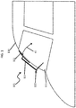
FIG. 1 is a schematic illustration of external components of a WWS in accordance with embodiments; -
FIG. 2 is a schematic diagram of components of a WWS in accordance with embodiments; -
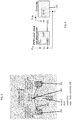
FIG. 3 is an illustration of a layout of a measurement system of a WWS in accordance with embodiments; -
FIG. 4 is a circuit diagram of components of a measurement system and a controller of a WWS in accordance with embodiments; -
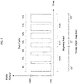
FIG. 5 is a graphical depiction of a relationship between a duty cycle PWM output and a position of a wiper trigger in accordance with embodiments; and -
FIG. 6 is a flow diagram illustrating a method of operating a WWS in accordance with embodiments. - These and other advantages and features will become more apparent from the following description taken in conjunction with the drawings.
- A conventional WWS can include an intelligent device with a controller or processor that provides a motor commutation sequence and monitors system faults, an internal wiper trigger that detects an end of sweep position of an external wiper blade, a park sensor feedback system with an end of sweep (EoS) sensor that detects the end of sweep position of the WWS by monitoring the internal wiper trigger, Hall sensor feedback to measure a speed of a motor of the WWS, motor current feedback to monitor motor winding currents, motor winding temperature feedback to monitor temperatures of the motor windings, a mechanical gear train and four bar link mechanism and a wiper arm and blade. The mechanical gear train and the four bar link mechanism converts rotary motion of the motor to oscillatory motion and the wiper arm and blade is driven by the oscillatory motion to wipe the windshield.
- Thus, in the conventional WWS, it is seen that Hall sensors are used to detect a speed of the motor. As such, any disconnections in Hall sensor signal lines can lead to system failures. In addition, the conventional WWS can include a worm gear that acts as a mechanical brake and a failure of the worm gear teeth can lead to an undesirable movement of the WWS from a park position. The conventional WWS does not have mechanism to detect this movement due to worm gear failure or other mechanical failures. That is, in the conventional WWS, Hall sensors are used for motor speed measurement but Hall sensors measure the speed only at motor ends and do not account for losses or faults in the mechanical gear train.
- As will be described below, a WWS is provided and configured with a capability of measuring a sweep angle of wiper blades by continuously monitoring a sweep angle of an internal wiper trigger. The continuous monitoring of the sweep angle is accomplished by way of strategically placed pulse width modulation (PWM) output linear Hall Effect sensors inside a wiper module. Thus, while a conventional WWS can be characterized in that the internal wiper trigger is used only to detect an EoS of external wiper blades, the internal wiper trigger experiences same external loads as that of the external wiper blades and this internal wiper trigger can be leveraged for sweep angle measurement of the external wiper blades as both the internal wiper trigger and the external wiper blades have the same sweep angle.
- With reference to
FIGS. 1-3 , a windshield wiper system (WWS) 101 is provided for use with anairframe 110, such as an airframe of a vehicle or an aircraft. Theairframe 110 is supportive of awindshield 111. The WWS 101 includes awiper blade assembly 120 and an internal control assembly 130 (seeFIG. 2 ). Thewiper blade assembly 120 includes awiper arm 121 and awiper blade 122. Thewiper blade 122 is attached to a distal end of thewiper arm 121 and is biased toward and onto thewindshield 111 by thewiper arm 121. Thewiper blade assembly 120 is configured to assume a parked position relative to thewindshield 111 unless a pilot/copilot command is entered to initiate a driving of thewiper blade assembly 120 whereby thewiper blade 122 moves across thewindshield 111 along a first sweep angle α1. Theinternal control assembly 130 is configured to drive thewiper blade assembly 120 across thewindshield 111 along the first sweep angle α1 such that the wiper blade element moves across thewindshield 111 to remove moisture or foreign object debris from thewindshield 111. - As shown in
FIGS. 2 and3 , the WWS 101 further includes aninternal wiper trigger 140 and ameasurement system 150. - The
internal wiper trigger 140 is disposed to move with thewiper blade assembly 120 and along a second sweep angle α2 (seeFIG. 3 ) that corresponds to the first sweep angle α1. In accordance with embodiments, theinternal wiper trigger 140 can be coupled to thewiper arm 121 or another suitable component of the wiper blade assembly 120 (i.e., an output shaft leading to the wiper arm 121) and is configured to generate a magnetic field. As a result of being coupled to thewiper arm 121 or another suitable component of thewiper blade assembly 120, theinternal wiper trigger 140 experiences a same or similar loading as thewiper blade assembly 120. - Since the
internal wiper trigger 140 is coupled to thewiper arm 121 or another suitable component of thewiper blade assembly 120, the second sweep angle α2 is a same sweep angle as the first sweep angle α1. - The
measurement system 150 is configured to monitor a position of theinternal wiper trigger 140 relative to the second sweep angle α2 from which a corresponding position of thewiper blade assembly 120 relative to the first sweep angle α1 is measurable. Themeasurement system 150 is further configured to output a sweep angle feedback signal SAFS, which corresponds to monitoring results, to theinternal control assembly 130. In accordance with embodiments, themeasurement system 150 can includeHall Effect sensors 151. As shown inFIG. 3 , theHall Effect sensors 151 can be disposed at opposite sides of an output shaft leading to thewiper blade assembly 120 or, more particularly, to thewiper arm 121 and are responsive to the magnetic field generated by theinternal wiper trigger 140. As such, theHall Effect sensors 151 generate a variable duty cycle output that corresponds to the interaction between theHall Effect sensors 151 and the internal wiper blade trigger 140 (as will be discussed below) and issue the variable duty cycle output to theinternal control assembly 130 as the SAFS. - As shown in
FIG. 2 , theinternal control assembly 130 includes acontroller 131, amotor 132 and a mechanical gear train and fourbar linkage 133. Thecontroller 131 is receptive of the sweep angle feedback signal SAFS and is configured to control a driving of thewiper blade assembly 120. Themotor 132 can include or be provided as a brushless DC (BLDC) motor and is operable by a motor drive control signal MDCS that is output from thecontroller 131. The mechanical gear train and fourbar linkage 133 is operably interposed between themotor 132 and thewiper blade assembly 120. Theinternal control assembly 130 further includes aposition feedback loop 134, which generates a position error signal PES for reception by thecontroller 131, a motorcurrent feedback loop 135, which generates a current error signal CES for reception by thecontroller 131, and a motor windingtemperature feedback loop 136, which generates a motor winding temperature error signal MWTES for reception by thecontroller 131. Theposition feedback loop 134, the motorcurrent feedback loop 135 and the motor windingtemperature feedback loop 136 are configured in parallel with each other and the position error signal PES, the current error signal CES and the motor winding temperature error signal MWTES are each derived from themotor 132. Thecontroller 131 is configured to control the driving of thewiper blade assembly 120 in accordance with at least the sweep angle feedback signal SAFS and, more particularly, thecontroller 131 is configured to control the driving of thewiper blade assembly 120 in accordance with the sweep angle feedback signal SAFS and in accordance with the position error signal PES, the current error signal CES and the motor winding temperature error signal MWTES. - With continued reference to
FIGS. 1-3 and with additional reference toFIGS. 4 and5 , an output of theHall Effect sensors 151 will be a variable duty cycle PWM output whose duty cycle is proportional to the magnetic flux density as shown inFIG. 5 . This PWM output can be interfaced directly to a GPIO pin of thecontroller 131 which, on receiving the PWM data, computes the second sweep angle α2 of theinternal wiper trigger 140. On extrapolating this data for the actual lengths of thewiper blade assembly 120, thecontroller 131 can compute the first sweep angle α1 as well as a position of thewiper blade 122. - The information computed by the
controller 131 can be communicated to a pilot or co-pilot over a communication interface. If the first sweep angle α1 is found to be deviating from a required specification and/or if a deviated sweep angle could obstruct the visibility of pilots, then an alarm or maintenance message could be communicated to replace theWWS 101 immediately. - The
Hall Effect sensors 151 can include or be provided as linear Hall Effect sensors and can be placed perpendicular to the magnetic field produced by theinternal wiper trigger 140. The generated analog voltage is provided by the following equation:
- The PWM output voltage generated is calibrated and interfaced with the
controller 131. The duty cycle of the output voltage is directly proportional to the second sweep angle α2. Hence by this approach, the first sweep angle α1 is effectively computed instead of discrete EoS signals of conventional WWSs. - The PWM output of the
Hall Effect sensors 151 can be interfaced to GPIO pins of thecontroller 131 as shown inFIG. 4 . The PWM output helps in eliminating errors due to noisy environments in themeasurement system 150. Since the duty cycle is directly proportional to the magnetic flux density around theHall Effect sensors 151, it is seen that the strength of the magnetic flux density around theHall Effect sensors 151 is directly proportional to the second sweep angle α2 of the internal wiper trigger 140 (where 'n' ofFIG. 5 represents the second sweep angle α2 of theinternal wiper trigger 140 from a specific defined position). - With reference to
FIG. 6 , a method of operating theWWS 101 is provided. As shown inFIG. 6 , the method includes driving a wiper blade assembly along a first sweep angle by a controller (601), monitoring a position of an internal wiper trigger disposed to move with the wiper blade assembly from which a corresponding position of the wiper blade assembly relative to the first sweep angle is measurable (602), outputting a sweep angle feedback signal corresponding to results of the monitoring to the controller (603) and controlling the driving of the wiper blade assembly by the controller in accordance with at least the sweep angle feedback signal (604). The controlling of the driving of the wiper blade assembly by the controller ofoperation 604 can be executed in accordance with the sweep angle feedback signal SAFS and in accordance with the position error signal PES, the current error signal CES and the motor winding temperature error signal MWTES. The monitoring ofoperation 602 can include generating a magnetic field at an internal wiper trigger disposed to move with the wiper blade assembly and generating a variable duty cycle output responsive to the magnetic field for issuance to the controller as the sweep angle feedback signal. - In accordance with embodiments, the sweep angle feedback signal has a negligible parallax error. In addition, the method further includes at least one of in-flight gear and shaft and real-time sweep angle monitoring based on the sweep angle feedback signal by the
controller 131, computing a speed of a motor configured to drive the wiper blade assembly by thecontroller 131 and facilitating an identification by an operator of ageing issues or failures of the motor, the wiper blade assembly or a gear train interposed between the motor and the wiper blade assembly. - Technical effects and benefits of the enclosure design of the present disclosure are the use of sensors to determine a sweep angle, angular velocity and acceleration of wiper externals and the provision of a redundant system for computing a speed of the motor during events such as Hall Effect sensor system failure. The present disclosure also provides for in-flight health monitoring of shafts and gears of a WWS and angle measurement in existing WWSs. The WWS of the present disclosure has a weight and cost which is substantially a same as a baseline and helps in requirement verification during testing.
- While the disclosure is provided in detail in connection with only a limited number of embodiments, it should be readily understood that the disclosure is not limited to such disclosed embodiments. Rather, the disclosure can be modified to incorporate any number of variations, alterations, substitutions or equivalent arrangements not heretofore described, but which are commensurate with the spirit and scope of the disclosure. Additionally, while various embodiments of the disclosure have been described, it is to be understood that the exemplary embodiment(s) may include only some of the described exemplary aspects. Accordingly, the disclosure is not to be seen as limited by the foregoing description, but is only limited by the scope of the appended claims.
Claims (15)
- A windshield wiper system (WWS) (101), comprising:a wiper blade assembly (120) drivable along a first sweep angle;an internal wiper trigger (140) disposed to move with the wiper blade assembly;a measurement system configured to monitor a position of the internal wiper trigger (140) from which a corresponding position of the wiper blade assembly relative to the first sweep angle is measurable and to output a sweep angle feedback signal corresponding to monitoring results; anda controller (131) receptive of the sweep angle feedback signal.
- The WWS according to claim 1, wherein the controller is configured to control a driving of the wiper blade assembly in accordance with the sweep angle feedback signal.
- The WWS according to claim 1 or 2, wherein the wiper blade assembly is configured to move across a windshield of a vehicle and comprises a wiper arm and a wiper blade attached to the wiper arm.
- The WWS according to any preceding claim, further comprising:a motor, which is operable by a motor drive control signal output from the controller; anda mechanical gear train and four bar linkage operably interposed between the motor and the wiper blade assembly,wherein the controller is configured to control the driving of the wiper blade assembly in accordance with the sweep angle feedback signal and in accordance with position, current and temperature feedback signals derived from the motor.
- The WWS according to any preceding claim, wherein the internal wiper trigger is coupled to the wiper blade assembly.
- The WWS according to any preceding claim, wherein:the internal wiper trigger generates a magnetic field, andthe measurement system is responsive to the magnetic field to monitor the position of the internal wiper trigger.
- The WWS according to claim 6, wherein:the measurement system comprises Hall Effect sensors positioned proximate to opposite ends of the second sweep angle,the Hall Effect sensors being configured to generate a variable duty cycle output responsive to the magnetic field and to issue the variable duty cycle output to the controller as the sweep angle feedback signal.
- The windshield wiper system (WWS) any preceding claim, further comprising:the internal wiper trigger further disposed to move along a second sweep angle corresponding to the first sweep angle;said measurement system configured to monitor a position of the internal wiper trigger relative to the second sweep angle from which said corresponding position of the wiper blade assembly relative to the first sweep angle is measurable.
- The WWS according to claim 8, wherein the controller is configured to control a driving of the wiper blade assembly in accordance with at least the sweep angle feedback signal.
- The WWS according to claim 8 or 9, wherein the second sweep angle is a same sweep angle as the first sweep angle.
- The WWS according to any of claims 8 to 10, wherein:the internal wiper trigger generates a magnetic field, andthe measurement system is responsive to the magnetic field to monitor the position of the internal wiper trigger relative to the second sweep angle.
- A method of operating a windshield wiper system (WWS), the method comprising:driving a wiper blade assembly along a first sweep angle by a controller;monitoring a position of an internal wiper trigger disposed to move with the wiper blade assembly from which a corresponding position of the wiper blade assembly relative to the first sweep angle is measurable;outputting a sweep angle feedback signal corresponding to results of the monitoring to the controller; andcontrolling the driving of the wiper blade assembly by the controller in accordance with at least the sweep angle feedback signal.
- The method according to claim 12, wherein the controlling of the driving of the wiper blade assembly by the controller is executed in accordance with the sweep angle feedback signal and in accordance with motor position, motor current and motor temperature feedback signals, and/or wherein the sweep angle feedback signal has a negligible parallax error.
- The method according to claim 12 or 13, wherein the monitoring comprises:generating a magnetic field at an internal wiper trigger disposed to move with the wiper blade assembly; andgenerating a variable duty cycle output responsive to the magnetic field for issuance to the controller as the sweep angle feedback signal.
- The method according to any of claims 12 to 14, further comprising at least one of:in-flight gear and shaft and real-time sweep angle monitoring based on the sweep angle feedback signal;computing a speed of a motor configured to drive the wiper blade assembly; andfacilitating an identification of ageing issues or failures of the motor, the wiper blade assembly or a gear train interposed between the motor and the wiper blade assembly.
Applications Claiming Priority (1)
| Application Number | Priority Date | Filing Date | Title |
|---|---|---|---|
| IN201911032887 | 2019-08-14 |
Publications (2)
| Publication Number | Publication Date |
|---|---|
| EP3778317A1 true EP3778317A1 (en) | 2021-02-17 |
| EP3778317B1 EP3778317B1 (en) | 2025-04-16 |
Family
ID=68762651
Family Applications (1)
| Application Number | Title | Priority Date | Filing Date |
|---|---|---|---|
| EP19212942.7A Active EP3778317B1 (en) | 2019-08-14 | 2019-12-02 | Dynamic sweep angle measurement for fault monitoring of windshield wiper systems |
Country Status (3)
| Country | Link |
|---|---|
| US (2) | US11772608B2 (en) |
| EP (1) | EP3778317B1 (en) |
| CA (1) | CA3064900A1 (en) |
Families Citing this family (1)
| Publication number | Priority date | Publication date | Assignee | Title |
|---|---|---|---|---|
| CN120043436B (en) * | 2025-04-23 | 2025-07-22 | 成都国营锦江机器厂 | Wiper retrace angle measurement method and system based on multi-modal dynamic feature fusion |
Citations (3)
| Publication number | Priority date | Publication date | Assignee | Title |
|---|---|---|---|---|
| EP0926025A2 (en) * | 1997-10-21 | 1999-06-30 | SWF Auto-Electric GmbH | Circuit to reduce the speed at reversing point of a windscreen wiper having a motor controlled by pulse width modulation |
| WO2009135820A1 (en) * | 2008-05-06 | 2009-11-12 | Robert Bosch Gmbh | Method for installing a wiper arm, method for adjusting or operating a windshield wiper device and windshield wiper device |
| WO2018216506A1 (en) * | 2017-05-22 | 2018-11-29 | 株式会社デンソー | Wiper drive device |
Family Cites Families (8)
| Publication number | Priority date | Publication date | Assignee | Title |
|---|---|---|---|---|
| US5355061A (en) | 1992-01-24 | 1994-10-11 | Grimes Aerospace Company | Windshield wiper system |
| US5404085A (en) | 1992-07-10 | 1995-04-04 | Rosemount Aerospace, Inc. | Multifunction aircraft windscreen wiper control system |
| CA2536676A1 (en) | 2003-09-15 | 2005-03-24 | Intier Automotive Closures Inc. | Reversing-motor windshield wiper system |
| US9061657B2 (en) | 2012-07-10 | 2015-06-23 | Asmo Co., Ltd. | Wiper device |
| WO2014010616A1 (en) | 2012-07-12 | 2014-01-16 | 株式会社ミツバ | Wiper control method and wiper control device |
| JP6650302B2 (en) * | 2015-03-19 | 2020-02-19 | 株式会社ミツバ | Brushless motor and wiper device |
| JP6790688B2 (en) | 2016-01-19 | 2020-11-25 | 株式会社デンソー | Vehicle wiper device and control method of vehicle wiper device |
| US11420594B2 (en) | 2017-08-28 | 2022-08-23 | Rosemount Aerospace Inc. | Configurable variable sweep variable speed wiper system |
-
2019
- 2019-11-21 US US16/690,936 patent/US11772608B2/en active Active
- 2019-12-02 EP EP19212942.7A patent/EP3778317B1/en active Active
- 2019-12-11 CA CA3064900A patent/CA3064900A1/en active Pending
-
2023
- 2023-07-07 US US18/348,584 patent/US11999320B2/en active Active
Patent Citations (3)
| Publication number | Priority date | Publication date | Assignee | Title |
|---|---|---|---|---|
| EP0926025A2 (en) * | 1997-10-21 | 1999-06-30 | SWF Auto-Electric GmbH | Circuit to reduce the speed at reversing point of a windscreen wiper having a motor controlled by pulse width modulation |
| WO2009135820A1 (en) * | 2008-05-06 | 2009-11-12 | Robert Bosch Gmbh | Method for installing a wiper arm, method for adjusting or operating a windshield wiper device and windshield wiper device |
| WO2018216506A1 (en) * | 2017-05-22 | 2018-11-29 | 株式会社デンソー | Wiper drive device |
Also Published As
| Publication number | Publication date |
|---|---|
| US20230347848A1 (en) | 2023-11-02 |
| EP3778317B1 (en) | 2025-04-16 |
| US20210046902A1 (en) | 2021-02-18 |
| US11999320B2 (en) | 2024-06-04 |
| BR102019026599A2 (en) | 2021-02-23 |
| US11772608B2 (en) | 2023-10-03 |
| CA3064900A1 (en) | 2021-02-14 |
Similar Documents
| Publication | Publication Date | Title |
|---|---|---|
| EP3110002B1 (en) | Motor rotation angle detection apparatus and electric power steering apparatus using same | |
| CN107444481B (en) | Rotation detection apparatus and electric power steering apparatus using the same | |
| US11084523B2 (en) | Vehicle-mounted device actuator and power steering device | |
| US7973504B2 (en) | Electric power steering control | |
| CN114269630A (en) | Power steering system for motor vehicle | |
| US11999320B2 (en) | Dynamic sweep angle measurement for fault monitoring of windshield wiper systems | |
| EP1479157B1 (en) | Method for the detection of abnormalities of electric motors | |
| EP3012191B1 (en) | Method for determining a state of a component in a high lift system of an aircraft, high lift system of an aircraft and aircraft having such a high lift system | |
| US20030090228A1 (en) | Position sensor and actuating system | |
| US20180115269A1 (en) | Electric motor power connection prognosis systems and methods | |
| CN113056386B (en) | Method for reliable monitoring of the functionality of electromagnetic transport devices | |
| US7500538B2 (en) | Control unit for electric power steering apparatus | |
| CN107010099B (en) | Emergency departure steering assist using estimated motor current | |
| EP4095003B1 (en) | Configurable variable sweep variable speed wiper system | |
| KR101090588B1 (en) | Fault tolerant control method of active front steering system | |
| SE545628C2 (en) | A steer-by-wire steering assembly | |
| CN113815719A (en) | Fault detection device and electric power steering device | |
| EP1672324A1 (en) | Control device for electric power steering device | |
| US20200055490A1 (en) | Fault diagnostics in aircraft windshield wiper systems | |
| EP2947004B1 (en) | Method for determining the position of a component in a high lift system of an aircraft, high lift system of an aircraft and aircraft | |
| US9211741B2 (en) | Position encoder systems | |
| US12021470B2 (en) | Method for identifying a malfunction in an inverter-motor assembly | |
| EP3889571B1 (en) | Method and system for diagnosing a rotation machine | |
| WO2026006113A1 (en) | Motor health monitoring | |
| BR102019026599B1 (en) | WINDSHIELD WIPER SYSTEM, AND, METHOD FOR OPERATING A WINDSHIELD WIPER SYSTEM CROSS-REFERENCE TO RELATED APPLICATIONS |
Legal Events
| Date | Code | Title | Description |
|---|---|---|---|
| PUAI | Public reference made under article 153(3) epc to a published international application that has entered the european phase |
Free format text: ORIGINAL CODE: 0009012 |
|
| STAA | Information on the status of an ep patent application or granted ep patent |
Free format text: STATUS: THE APPLICATION HAS BEEN PUBLISHED |
|
| AK | Designated contracting states |
Kind code of ref document: A1 Designated state(s): AL AT BE BG CH CY CZ DE DK EE ES FI FR GB GR HR HU IE IS IT LI LT LU LV MC MK MT NL NO PL PT RO RS SE SI SK SM TR |
|
| AX | Request for extension of the european patent |
Extension state: BA ME |
|
| STAA | Information on the status of an ep patent application or granted ep patent |
Free format text: STATUS: REQUEST FOR EXAMINATION WAS MADE |
|
| 17P | Request for examination filed |
Effective date: 20210816 |
|
| RBV | Designated contracting states (corrected) |
Designated state(s): AL AT BE BG CH CY CZ DE DK EE ES FI FR GB GR HR HU IE IS IT LI LT LU LV MC MK MT NL NO PL PT RO RS SE SI SK SM TR |
|
| STAA | Information on the status of an ep patent application or granted ep patent |
Free format text: STATUS: EXAMINATION IS IN PROGRESS |
|
| 17Q | First examination report despatched |
Effective date: 20220615 |
|
| GRAP | Despatch of communication of intention to grant a patent |
Free format text: ORIGINAL CODE: EPIDOSNIGR1 |
|
| STAA | Information on the status of an ep patent application or granted ep patent |
Free format text: STATUS: GRANT OF PATENT IS INTENDED |
|
| INTG | Intention to grant announced |
Effective date: 20241115 |
|
| GRAS | Grant fee paid |
Free format text: ORIGINAL CODE: EPIDOSNIGR3 |
|
| GRAA | (expected) grant |
Free format text: ORIGINAL CODE: 0009210 |
|
| STAA | Information on the status of an ep patent application or granted ep patent |
Free format text: STATUS: THE PATENT HAS BEEN GRANTED |
|
| AK | Designated contracting states |
Kind code of ref document: B1 Designated state(s): AL AT BE BG CH CY CZ DE DK EE ES FI FR GB GR HR HU IE IS IT LI LT LU LV MC MK MT NL NO PL PT RO RS SE SI SK SM TR |
|
| REG | Reference to a national code |
Ref country code: GB Ref legal event code: FG4D |
|
| REG | Reference to a national code |
Ref country code: CH Ref legal event code: EP Ref country code: DE Ref legal event code: R096 Ref document number: 602019068646 Country of ref document: DE |
|
| REG | Reference to a national code |
Ref country code: IE Ref legal event code: FG4D |
|
| REG | Reference to a national code |
Ref country code: NL Ref legal event code: MP Effective date: 20250416 |
|
| PG25 | Lapsed in a contracting state [announced via postgrant information from national office to epo] |
Ref country code: NL Free format text: LAPSE BECAUSE OF FAILURE TO SUBMIT A TRANSLATION OF THE DESCRIPTION OR TO PAY THE FEE WITHIN THE PRESCRIBED TIME-LIMIT Effective date: 20250416 |
|
| REG | Reference to a national code |
Ref country code: AT Ref legal event code: MK05 Ref document number: 1785409 Country of ref document: AT Kind code of ref document: T Effective date: 20250416 |
|
| PG25 | Lapsed in a contracting state [announced via postgrant information from national office to epo] |
Ref country code: FI Free format text: LAPSE BECAUSE OF FAILURE TO SUBMIT A TRANSLATION OF THE DESCRIPTION OR TO PAY THE FEE WITHIN THE PRESCRIBED TIME-LIMIT Effective date: 20250416 Ref country code: ES Free format text: LAPSE BECAUSE OF FAILURE TO SUBMIT A TRANSLATION OF THE DESCRIPTION OR TO PAY THE FEE WITHIN THE PRESCRIBED TIME-LIMIT Effective date: 20250416 Ref country code: PT Free format text: LAPSE BECAUSE OF FAILURE TO SUBMIT A TRANSLATION OF THE DESCRIPTION OR TO PAY THE FEE WITHIN THE PRESCRIBED TIME-LIMIT Effective date: 20250818 |
|
| REG | Reference to a national code |
Ref country code: LT Ref legal event code: MG9D |
|
| PG25 | Lapsed in a contracting state [announced via postgrant information from national office to epo] |
Ref country code: GR Free format text: LAPSE BECAUSE OF FAILURE TO SUBMIT A TRANSLATION OF THE DESCRIPTION OR TO PAY THE FEE WITHIN THE PRESCRIBED TIME-LIMIT Effective date: 20250717 Ref country code: NO Free format text: LAPSE BECAUSE OF FAILURE TO SUBMIT A TRANSLATION OF THE DESCRIPTION OR TO PAY THE FEE WITHIN THE PRESCRIBED TIME-LIMIT Effective date: 20250716 |
|
| PG25 | Lapsed in a contracting state [announced via postgrant information from national office to epo] |
Ref country code: PL Free format text: LAPSE BECAUSE OF FAILURE TO SUBMIT A TRANSLATION OF THE DESCRIPTION OR TO PAY THE FEE WITHIN THE PRESCRIBED TIME-LIMIT Effective date: 20250416 |
|
| PG25 | Lapsed in a contracting state [announced via postgrant information from national office to epo] |
Ref country code: BG Free format text: LAPSE BECAUSE OF FAILURE TO SUBMIT A TRANSLATION OF THE DESCRIPTION OR TO PAY THE FEE WITHIN THE PRESCRIBED TIME-LIMIT Effective date: 20250416 |
|
| PG25 | Lapsed in a contracting state [announced via postgrant information from national office to epo] |
Ref country code: HR Free format text: LAPSE BECAUSE OF FAILURE TO SUBMIT A TRANSLATION OF THE DESCRIPTION OR TO PAY THE FEE WITHIN THE PRESCRIBED TIME-LIMIT Effective date: 20250416 |
|
| PG25 | Lapsed in a contracting state [announced via postgrant information from national office to epo] |
Ref country code: AT Free format text: LAPSE BECAUSE OF FAILURE TO SUBMIT A TRANSLATION OF THE DESCRIPTION OR TO PAY THE FEE WITHIN THE PRESCRIBED TIME-LIMIT Effective date: 20250416 |
|
| PG25 | Lapsed in a contracting state [announced via postgrant information from national office to epo] |
Ref country code: RS Free format text: LAPSE BECAUSE OF FAILURE TO SUBMIT A TRANSLATION OF THE DESCRIPTION OR TO PAY THE FEE WITHIN THE PRESCRIBED TIME-LIMIT Effective date: 20250716 |
|
| PG25 | Lapsed in a contracting state [announced via postgrant information from national office to epo] |
Ref country code: IS Free format text: LAPSE BECAUSE OF FAILURE TO SUBMIT A TRANSLATION OF THE DESCRIPTION OR TO PAY THE FEE WITHIN THE PRESCRIBED TIME-LIMIT Effective date: 20250816 |
|
| PG25 | Lapsed in a contracting state [announced via postgrant information from national office to epo] |
Ref country code: LV Free format text: LAPSE BECAUSE OF FAILURE TO SUBMIT A TRANSLATION OF THE DESCRIPTION OR TO PAY THE FEE WITHIN THE PRESCRIBED TIME-LIMIT Effective date: 20250416 |
|
| PGFP | Annual fee paid to national office [announced via postgrant information from national office to epo] |
Ref country code: DE Payment date: 20251126 Year of fee payment: 7 |
|
| PGFP | Annual fee paid to national office [announced via postgrant information from national office to epo] |
Ref country code: GB Payment date: 20251119 Year of fee payment: 7 |
|
| PG25 | Lapsed in a contracting state [announced via postgrant information from national office to epo] |
Ref country code: DK Free format text: LAPSE BECAUSE OF FAILURE TO SUBMIT A TRANSLATION OF THE DESCRIPTION OR TO PAY THE FEE WITHIN THE PRESCRIBED TIME-LIMIT Effective date: 20250416 Ref country code: SM Free format text: LAPSE BECAUSE OF FAILURE TO SUBMIT A TRANSLATION OF THE DESCRIPTION OR TO PAY THE FEE WITHIN THE PRESCRIBED TIME-LIMIT Effective date: 20250416 |
|
| PGFP | Annual fee paid to national office [announced via postgrant information from national office to epo] |
Ref country code: FR Payment date: 20251120 Year of fee payment: 7 |
|
| REG | Reference to a national code |
Ref country code: DE Ref legal event code: R097 Ref document number: 602019068646 Country of ref document: DE |
|
| PG25 | Lapsed in a contracting state [announced via postgrant information from national office to epo] |
Ref country code: CZ Free format text: LAPSE BECAUSE OF FAILURE TO SUBMIT A TRANSLATION OF THE DESCRIPTION OR TO PAY THE FEE WITHIN THE PRESCRIBED TIME-LIMIT Effective date: 20250416 |
|
| PG25 | Lapsed in a contracting state [announced via postgrant information from national office to epo] |
Ref country code: EE Free format text: LAPSE BECAUSE OF FAILURE TO SUBMIT A TRANSLATION OF THE DESCRIPTION OR TO PAY THE FEE WITHIN THE PRESCRIBED TIME-LIMIT Effective date: 20250416 |
|
| PG25 | Lapsed in a contracting state [announced via postgrant information from national office to epo] |
Ref country code: RO Free format text: LAPSE BECAUSE OF FAILURE TO SUBMIT A TRANSLATION OF THE DESCRIPTION OR TO PAY THE FEE WITHIN THE PRESCRIBED TIME-LIMIT Effective date: 20250416 Ref country code: SK Free format text: LAPSE BECAUSE OF FAILURE TO SUBMIT A TRANSLATION OF THE DESCRIPTION OR TO PAY THE FEE WITHIN THE PRESCRIBED TIME-LIMIT Effective date: 20250416 |
|
| PG25 | Lapsed in a contracting state [announced via postgrant information from national office to epo] |
Ref country code: IT Free format text: LAPSE BECAUSE OF FAILURE TO SUBMIT A TRANSLATION OF THE DESCRIPTION OR TO PAY THE FEE WITHIN THE PRESCRIBED TIME-LIMIT Effective date: 20250416 |
|
| PLBE | No opposition filed within time limit |
Free format text: ORIGINAL CODE: 0009261 |
|
| STAA | Information on the status of an ep patent application or granted ep patent |
Free format text: STATUS: NO OPPOSITION FILED WITHIN TIME LIMIT |
|
| REG | Reference to a national code |
Ref country code: CH Ref legal event code: L10 Free format text: ST27 STATUS EVENT CODE: U-0-0-L10-L00 (AS PROVIDED BY THE NATIONAL OFFICE) Effective date: 20260225 |
|
| 26N | No opposition filed |
Effective date: 20260119 |