EP3778135B1 - Convertible sawhorse and work table - Google Patents
Convertible sawhorse and work table Download PDFInfo
- Publication number
- EP3778135B1 EP3778135B1 EP20191053.6A EP20191053A EP3778135B1 EP 3778135 B1 EP3778135 B1 EP 3778135B1 EP 20191053 A EP20191053 A EP 20191053A EP 3778135 B1 EP3778135 B1 EP 3778135B1
- Authority
- EP
- European Patent Office
- Prior art keywords
- sawhorse
- leg
- disposed
- worktable
- slider
- Prior art date
- Legal status (The legal status is an assumption and is not a legal conclusion. Google has not performed a legal analysis and makes no representation as to the accuracy of the status listed.)
- Active
Links
Images

















Classifications
-
- B—PERFORMING OPERATIONS; TRANSPORTING
- B25—HAND TOOLS; PORTABLE POWER-DRIVEN TOOLS; MANIPULATORS
- B25H—WORKSHOP EQUIPMENT, e.g. FOR MARKING-OUT WORK; STORAGE MEANS FOR WORKSHOPS
- B25H1/00—Work benches; Portable stands or supports for positioning portable tools or work to be operated on thereby
- B25H1/02—Work benches; Portable stands or supports for positioning portable tools or work to be operated on thereby of table type
- B25H1/04—Work benches; Portable stands or supports for positioning portable tools or work to be operated on thereby of table type portable
-
- B—PERFORMING OPERATIONS; TRANSPORTING
- B25—HAND TOOLS; PORTABLE POWER-DRIVEN TOOLS; MANIPULATORS
- B25H—WORKSHOP EQUIPMENT, e.g. FOR MARKING-OUT WORK; STORAGE MEANS FOR WORKSHOPS
- B25H1/00—Work benches; Portable stands or supports for positioning portable tools or work to be operated on thereby
- B25H1/06—Work benches; Portable stands or supports for positioning portable tools or work to be operated on thereby of trestle type
-
- B—PERFORMING OPERATIONS; TRANSPORTING
- B25—HAND TOOLS; PORTABLE POWER-DRIVEN TOOLS; MANIPULATORS
- B25H—WORKSHOP EQUIPMENT, e.g. FOR MARKING-OUT WORK; STORAGE MEANS FOR WORKSHOPS
- B25H1/00—Work benches; Portable stands or supports for positioning portable tools or work to be operated on thereby
- B25H1/14—Work benches; Portable stands or supports for positioning portable tools or work to be operated on thereby with provision for adjusting the bench top
- B25H1/18—Work benches; Portable stands or supports for positioning portable tools or work to be operated on thereby with provision for adjusting the bench top in inclination
Definitions
- the invention is directed to an assembly which can be moved between a first position where it can be used as a sawhorse to a second position where it can be used as a worktable. Examples are known from EP3253536A1 , US2018/161973A1 or US2005/230188A1 .
- Portable sawhorse assemblies which can be switched between sawhorse and workpiece support configurations are known, for example as disclosed in U.S. Patent No. 6,659,440 entitled Portable Support Assembly for a Workpiece, owned by the assignee of the present invention.
- the structure disclosed therein requires the workpiece support table to be fully disconnected from the sawhorse elements and separately pivoted about its support rods to be moved from the workpiece support configuration into the sawhorse or storage condition.
- EP3253536A1 shows the preamble of independent claims 1 and 8.
- the invention is direction to an assembly having a sawhorse including first and second sawhorse legs pivotably connected to each other at one end thereof to define an upper end of the sawhorse.
- the first and second sawhorse legs are pivotable relative to each other between a closed sawhorse position in which the first and second sawhorse legs are folded substantially against each other and an open sawhorse position in which the first and second sawhorse legs are spaced apart from each other below the upper end.
- a worktable defines first and second worktable sides.
- a first rack and a second rack are secured to the worktable. The first rack is disposed adjacent the first table side and the second rack is disposed adjacent the second table side.
- a first gear disposed in engagement with the first rack and a second gear is disposed in engagement with the second rack.
- a gear axis rod extends and is secured adjacent a first end to the first gear and adjacent a second end to the second gear.
- a support leg is pivotably secured adjacent one end thereof to the first sawhorse leg and pivotably secured adjacent a second end thereof to the worktable. In a first condition of the assembly, the sawhorse is in the closed sawhorse position, the worktable is disposed outwardly adjacent of the second sawhorse leg and the support leg is disposed outwardly adjacent of the first sawhorse leg.
- the assembly may be moved to a second condition in which the sawhorse is in the open sawhorse position, the worktable is supported at an inward location thereof by the upper end of the sawhorse and the worktable is supported adjacent an end thereof by the support leg.
- the worktable slides above the upper end of the sawhorse during at least a portion of the movement between the first and second conditions with the racks causing simultaneous rotation of said gear via the gear rod.
- the invention is directed to an assembly having a sawhorse including a first sawhorse leg and a second sawhorse leg pivotably connected to each other at the upper ends thereof.
- the sawhorse legs include sawhorse feet at the lower ends thereof.
- Two pivot support rods are each pivotably mounted at a lower end thereof to the feet of the first sawhorse leg and have a sliding rod disposed therethrough adjacent an upper end thereto.
- a worktable has a lower surface and two pairs of flanges, each of the pair of flanges is disposed at a corner of the worktable. Each flange has a channel formed therethrough.
- One of the sliding rods is slidably disposed at either end thereof in one channel of one flange of a pair of flanges.
- the work table has a first rack and a second rack disposed on the lower surface.
- a first gear is disposed in engagement with the first rack and a second gear is disposed in engagement with the second rack.
- a gear axis rod extends between and is engaged with the first gear and the said second gear.
- Convertible sawhorse and work table 1 includes worktable 10, two pivoting support rods 130, first sawhorse leg 110, second sawhorse leg 120, and tray 150 disposed between first sawhorse leg 110 and second sawhorse leg 120.
- convertible sawhorse and work table 1 is in its fully open position with upper surface 12 of worktable 10 disposed substantially horizontally and supported centrally by first sawhorse leg 110 and second sawhorse leg 120 and adjacent two corners by pivoting support rods 130.
- convertible sawhorse and work table 1 is shown in a fully collapsed position with first sawhorse leg 110 and second sawhorse leg 120 disposed adjacent each other with tray 150 collapsed and fitting therebetween so as to not be shown, worktable 10 folded against second sawhorse leg 120, pivoting support rods 130 folded against first sawhorse leg 110. Worktable 10 is locked to second sawhorse leg 120 via protrusion 125 on second sawhorse leg 120 fitting within lock opening 13 formed on worktable 10 (see Figure 3a ).
- convertible sawhorse and worktable 1 is shown in an intermediate position with first sawhorse leg 110 pivoted away from second sawhorse leg 120 to support the structure, tray 150 unfolded therebetween, and worktable 10 disposed adjacent second sawhorse leg 120.
- rear wall 11 of worktable 10 is horizontally disposed and overlies the top surface of first sawhorse leg 110, which itself overlaps the top surface of second sawhorse leg 120, and the outer surface there of functions as a sawhorse surface.
- Figure 2c shows an intermediate position in which convertible sawhorse and work table 1 is being moved between the positions shown in Figure 2b and Figure 2d .
- Worktable 10 includes upper work surface 12 and front wall 19 and two side walls 14 extending downwardly therefrom.
- Rear wall 11 includes a slanted upper surface, an intermediate surface angled with respect to the upper surface and a lower surface at a further angle, and as noted above the upper surface may serves as the sawhorse surface when the assembly is in the sawhorse configuration.
- Rack channels 22 are formed by walls extending downwardly from the lower surface in a generally longitudinal direction between from a position rearward of front wall 19 to a position forward of rear wall 11 and are generally parallel to side walls 14 and disposed laterally inwardly thereof.
- Each rack channel 22 is formed by two walls each having three square shaped slots 22b at the lower ends. Screw-threaded projections 22a are formed on the lower surface of worktable 10 above the location of slots 22. Various circular and oblong slots may be formed through worktable 10.
- Worktable 10 further includes handle receiving portion 16 which includes an opening formed through front wall 19.
- the rear surface of handle receiving portion 16 includes through channel 16a.
- the lower surface of handle receiving portion 16 includes three through slots 16a.
- Handle 15, (shown in Figures 4a , 4b and 5a ) includes three protrusions which are snap fitted into slots 16a to secure handle 15 in handle receiving portion 16.
- Louvered support walls 17 extends downwardly from the lower surface of work surface 12 and includes two through slots 17a.
- Support wall 17 along with two side walls 17b define a generally square region 17c into which push button 40 is received.
- Screw-threaded projection 18 extends downwardly from the lower surface of work surface 12 behind handle receiving portion 16 and within region 17c.
- Push button opening 20 (see Figure 1a ) is formed through work surface 12 at a location above handle receiving portion 16. Further lateral walls 17d extend transversely from the laterally outward sides of rack channels 22 to the inner surface of each side wall 14. Lock opening 13 is which may include two spring loaded tabs is formed in the lower surface of front wall 19 below handle receiving portion 16.
- Worktable 10 further includes outer flanges 24 and inner flanges 26 extending downwardly from work surface 12 at the rear corners thereof, generally forward of rear wall 11.
- Each outer flange 24 includes a C-shaped channel 24a and each inner flange 26 includes C-shaped channel 26a formed therethrough.
- Each of a pair of channels 24a and 26a are aligned with each other to form a single travel channel which will hereinafter be denoted as slide channel 24a/26a.
- cross rods 27 extend between each of a pair of outer flange 24 and inner flange 26 at a location midway along channels 24a and 26a.
- Geometric tooth 27a extends from each rod 27, generally rearwardly towards rear wall 11.
- Rack 30 includes lower wall 36 and upper wall 38 with primary wall 31 extending therebetween.
- Lower wall 36 extends outwardly from primary wall 31 to a greater extent than upper wall 38 so as to give rack 30 an overall inverted T-shaped configuration.
- Rack teeth 32 are formed on lower wall 36.
- Strengthening ribs 35 extending between lower wall 36 and upper wall 38.
- Tabs 34 extend laterally from three of ribs 35 and include semi-circular screw openings 34a.
- racks 30 are disposed in rack channels 22 of worktable 10 with tabs 34 fitting within square shaped slots 22b.
- Racks 30 are secured to worktable 10 by screws (not shown) which fit through openings 34a and into screw-threaded projections 22a.
- Push button 40 includes a main body portion having a cylindrical pivot axis 44 formed transversely across an upper surface at a generally midway location.
- Push tab or surface 49 is formed at a forward end of push button 40.
- Through hole 46 and raised, non-through openings 48 are formed between axis 44 and push surface 49.
- Two hooked push button teeth 42 extend from the rear of push button 44.
- push button 40 is disposed adjacent the lower surface of worksurface 12 of worktable 10 within square region 17c.
- Push tab 49 is fitted through channel 16a formed in handle receiving portion 16 and is disposed in push button opening 20 in worktable 10.
- Screw threaded projection 18 fits within through hole 46. Teeth 42 extend through support wall openings 17a. Pivot axis 44 snap fits within four semi-circular downward projections 18a formed on the lower surface of work surface 12 to pivotably secure push button 40 to worktable 10.
- Lock cover 50 includes two hollow cylinders 52 on either side and lock cover screw column 54 centrally located therebetween. With reference to Figures 3b , 4a and 5b , lock cover 50 is disposed beneath push button 40, with lock cover screw column 54 disposed through hole 46 and received about screw threaded projection 18. A screw secures lock cover 50 to the lower surface of work surface 12 of worktable 10, with push button 40 disposed therebetween. Springs are secured within hollow cylinders 52, in contact with the lower surfaces of non-through openings 48 of push button 40, to thereby bias push button 40 upwardly forward of axis 44, with push tab 49 thereby raised to an upper most location within opening 20, and teeth 42 biased downwardly. Therefore, pushing tab 49 causes push button 40 to pivot about axis 44 and raises teeth 42 upwardly.
- First sawhorse leg 110 includes side leg elements 110a and 110b extending vertically, and upper leg element 111 and lower leg element 113 extending laterally therebetween.
- Upper leg element 111 includes a pair of rack slots 116 formed adjacent and extending through the side ends approximately above or just inward of leg elements 110a and 110b.
- Rack retaining projections 117 project into rack slots 116 at an upper open end.
- Openings 118 are formed on an inward surface of upper leg element 111, at a location just below rack slots 116.
- one slider base 60 is disposed within each opening 118, and one such slider base 60 is shown in Figure 8a .
- Raised rearwardly hooked teeth 115 are formed in further openings of upper leg element 111, laterally inward of and at a location above each opening 118.
- Multiple circular through hole projections 119 extend inwardly from upper leg element 111, are spaced from each other, and extend laterally across the inner surface.
- Curved teeth 114 project upwardly from lower leg element 113, are spaced from each other, and face towards a common axis in an alternating arrangement, that is, the curved outer side of teeth 114 alternately face the forward or rearward direction relative to lower leg element 113.
- Side leg elements 110a and 110b each extend outwardly downwardly from lower leg element 113 into feet 112.
- Each foot 112 includes foot slot 112a.
- Circular through opening 112b is formed in foot 112 outwardly of slot 112a and corresponding circular opening 112c extends within foot 112 on the other side of slot 112a.
- a ledge is formed behind opening 112c with foot 112.
- Second saw horse leg 120 includes side leg elements 120a and 120b extending vertically, and upper leg element 121 and lower leg element 123 extending laterally therebetween.
- Upper leg element 121 includes spaced extending projections 126 projecting from an upper surface and forming slots 126a therebetween.
- Curved teeth 124 project upwardly from lower leg element 123, are spaced from each other, and face towards a common axis in an alternating arrangement, that is, the curved outer side of teeth 124 alternately face the forward or rearward direction relative to leg element 123.
- Protrusion 125 extends from the outer side of lower leg element 123 at a central location just below teeth 124.
- Side leg elements 120a and 120b extend outwardly downwardly from lower leg element 113 and extend into feet 122.
- Multiple flexible column shaped protrusions 127 are spaced from each other and extend laterally adjacent the top surface of leg element 121.
- Tray 150 includes left and right tray portions 151 which are identical to each other. Tray portions 151 include four tabs 153 extending from one side surface. Protrusion 153a extends downwardly from each tab 153. Circular columns 153b extend between left and right projections extending downwardly from each tab 153. Semi-circular columns 154 extend from the same side surface, alternating with tabs 153. Openings 155 are formed through tray portions 151 behind each column 154. Tray 150 is assembled with each column 154 pivotably disposed about one circular column 153b, with protrusion 153a snapped into a corresponding hole 155. Protrusions 153a move out of holes 155 when tray portions 151 pivot from the open position to a fully closed position in which tray portions 151 are adjacent each other. Each tray portion 151 also includes spaced columns 152 at an opposite side from tabs 153.
- first sawhorse leg 110 is assembled to second sawhorse leg 120 with the upper surface of leg element 121 of second sawhorse leg 120 fitting below an overhanging portion of upper leg element 111 of first sawhorse leg 110.
- Flexible column shaped protrusions 127 of second sawhorse 120 are snap-fitted into circular through hole projections 119 of first sawhorse leg 110 to pivotably secure the sawhorse legs together around an axis created through protrusions 127.
- tray 150 are snap fitted into teeth 114 of first sawhorse leg 110 and teeth 124 of second sawhorse leg 120 to pivotably secure tray 150 to each sawhorse leg.
- trays portions 151 pivot relative to and are folded against each other and are generally received in an open space formed between the inner surfaces of each sawhorse leg.
- Slider base 60 includes flexible slider base protrusions 62 extending from both sides thereof. Slider base 60 also includes three forward spaced projections 64, each including circular through hole 64a. With reference to Figures 5e and 8a , one slider base 60 is slidably disposed into one of openings 118 formed in first leg 110. Rectangular windows 118a are formed in the rear of each opening 118 on either side thereof. When slider base 60 is slid into opening 118, protrusions 62 snap into each window 118a to secure slider base 60 therein.
- Slider housing 70 includes side walls 72 defining an open region therebetween. Ledges 76 extend from the top of each side wall 72 partially covering the open region. Each side wall 72 incudes a through opening 72a at a forward end, and five spaced projections 74 at a rearward end. Each projection 74 includes a circular opening 74a formed therethrough.
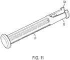
- slider pivot pin 80 is disclosed. Pivot pin 80 includes two flexible prongs 82 at one end each having forward tab 82a.
- slider housing 70 is secured to slider base 60 by interlacing projections 74 with projections 64 with openings 64a aligned with openings 74a, and with pivot pin 80 disposed through all of the aligned openings. Prongs 82 flex outwardly with tips 82a disclosed outwardly of one of side walls 72 to prevent pin 80 from sliding laterally and thereby preventing slider housing 70 from laterally moving relative to slider base 60. Slider housing 70 is thereby secured to first sawhorse leg 110 adjacent upper leg element 11. However, slider housing 70 may freely pivot about pin 80 relative to both slider base 60 and first sawhorse leg 110.
- gear axis rod 90 is disclosed.
- Gear axis rod includes screw-threaded openings 90a adjacent each end.
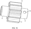
- gear 92 is disclosed.
- Gear 92 includes gear teeth 94 disposed about a hollow central hub and hollow circular projections 96 extending laterally from each side of the hub.
- One of projections 96 includes transverse through holes 96a extending through both sides thereof.
- one gear 92 is disposed in the open region of each slider housing 70.
- Gear axis 90 is disposed through the hollow central hub and projections 96 of each gear 92, with screw-threaded openings 90a disposed beneath though holes 96a, and a screw disposed therein to secure gears 92 near both ends of gear axis 90.
- Gear axis 90 also extends through openings 72a of both pivoting slider housings 70.
- worktable 10 is slidably secured to first sawhorse leg 110 by disposing racks 30 secured thereto in rack slots 116.
- Rack retaining projections 117 are disposed above rack lower wall 36 to preclude vertical motion of racks 30 and thus worktable 10 relative to first sawhorse leg 110.
- Racks 30 are also fitted into the open regions of pivotable slider housing 70, with ledges 76 extending above lower walls 36.
- Rack teeth 32 engage gears 92. Therefore, worktable 10 and all elements attached thereto including racks 30 and push button 40 may move laterally across the upper surface of first sawhorse leg 110, with racks 30 sliding through slots 116.
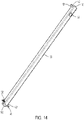
- Pivoting support rod 130 includes circular through openings 132 formed through and near a lower end thereof and circular through openings 134 formed through and near an upper end thereof, and rectangular through opening 136 formed adjacent and below opening 134.
- profile cap 140 is disclosed.
- Profile cap 140 is substantially hollow and is defined by four side walls 145 and upper surface 141.
- Circular through hole 141a is formed through surface 141.
- Circular through holes 145a are formed through two opposite side surfaces 145.
- One profile cap 140 is disposed through the lower open end of each support rod 130, with through holes 145a aligned with circular openings 132.
- a second profile pad 140 is disposed in the upper end of each support rod 130 with through holes 145a aligned with circular openings 134.
- cylindrical sliding rod 142 is disclosed and includes screw-threaded opening 142a formed therethrough.
- one pivoting support rod 130 is disposed on each foot 112 of first sawhorse 110.
- the lower surface of support rod 130 having profile pad 140 disposed therein is inserted into foot slot 112a, with circular openings 132 aligned with circular openings 112b and 112c.
- Slider pivot pin 80 is disposed through openings 112b, openings 132 and holes 145a, with prongs 82 extending into circular opening 112c.
- Prongs 82 flex outwardly to secure tabs 82a behind a ledge formed within openings 112c to retain support rod 130 on first sawhorse leg 110, while allowing pivoting movement of support rod 130 about an axis defined by pin 80 towards and away from first sawhorse leg 110.
- a second profile pad 140 is disclosed in the upper open end of support rod 130, with though holes 145 aligned with openings 134.
- Cylindrical sliding rod 142 is disposed through hole 145 and openings 134 so as to include ends extending outwardly from either side of support rod 130.
- a screw is inserted through opening 141b of pad 140 and is screwed into the threaded openings 142a of rod 140 to secure both pad 140 and rod 142 relative to support rod 130.
- the upper end of support rod 130 is disposed between each pair of inner flange 26 and outer flange 24, with one end of rod 142 extending through channel 26a and the opposite end extending though channel 26b. Therefore, the upper end of support rods 130 can be moved from a location adjacent the upper end of channels 24a/26a to a location adjacent the lower end, with the outer ends of rod 42 sliding in the channels.
- geometric tooth 27a is disposed in rectangular through opening 136.
- convertible sawhorse and work table 1 is in the closed position.
- Worktable 10 and racks 30 secured thereto are pivoted downward so as to extend adjacent and generally parallel to second sawhorse leg 120.
- slider 70 is pivoted downwardly about pivot pin 80 relative to slider base 60, which is secured within first sawhorse leg 110, such that slider 70 also extends downwardly generally adjacent and generally parallel to second sawhorse leg 120.
- Sliding rod 142 is in a hooked part of channel 24a/26a. Since racks 30 and sliders 70 both pivot, gears 92 remain in contact with rack teeth 32.
- first sawhorse leg 110 and second sawhorse leg 120 are pivoted away from each other to their fully open position relative to each other.
- Convertible sawhorse and work table 1 is now in the sawhorse position.
- Rear wall 11 of worktable 10 is now the upper most surface of the assembly and serves as the sawhorse upper surface.
- Sliding rod 142 has moved out of the hooked part of channel 24a/26a.
- the configuration of worktable 10, rack 30 and slider 70 relative to second sawhorse leg 120 has not changed, that is, they extend generally parallel and adjacent thereto.
- Tray 150 has pivoted to the fully open position.
- Geometric teeth 27a of cross rods 27 extend substantially parallel to the forward walls of pivoting support rods 130.
- worktable 110 has been pivoted in the clockwise direction about sliding rod 142, away from second sawhorse leg 120 and is now disposed substantially horizontally above first sawhorse leg 110.
- Slider 70 has pivoted relative to slider housing 60 about pivot pin 80 and remains extending substantially parallel to worktable 110.
- the pivoting of worktable 10 relative to the upper surface of first sawhorse leg 110 has caused sliding rod 142 to slide along channel 24a/26a to an intermediate position.
- the pivoting of worktable 110 also causes geometric teeth 27a of cross rods 27 to pivot to a position where they extend substantially perpendicular the forward walls of support rods 130 but are spaced therefrom.
- worktable 10 has been slid rearwardly (to the right in the Figures) to the fully open position.
- rack teeth 32 engage gears 92 linked by gear axis 90 to ensure that that side walls 14 of worktable 10 move evenly with respect to each other such that the worktable always stays square relative to the top of first sawhorse leg 110, that is, side walls 14 of worktable 10 remain parallel to the sides of the upper first saw horse leg 110.
- Rearward movement of worktable 10 relative to sawhorse leg 110 forces sliding rod 142 to slide upwardly in channel 24a/26a to the uppermost end of the channel, at which point further rearward motion of worktable 10 is precluded.
- support wall 17 and side walls 17d of worktable 10 also contact the forward surface of upper leg element 111 to also preclude further rearward motion of worktable 10.
- Pivot support rods 130 pivot about pivot pins 80 in feet 112 to a position in which they are spaced from first sawhorse leg 110, and which is slightly past vertical.
- geometric teeth 27a of cross rods 27 are also moved rearwardly and lodge within rectangular openings 136 of pivoting support rods 130, which precludes upward movement of rear wall 11 of table 110 at the locations of support rods 130.
- Projections 117 in rack slots 116 preclude upward movement of worktable 110.
- teeth 42 of pushbutton 40 lodge behind raised teeth 115 of first sawhorse leg 110 to preclude forward movement of worktable 110 relative thereto, and convertible sawhorse and work table 1 is locked in the worktable position.
Landscapes
- Engineering & Computer Science (AREA)
- Mechanical Engineering (AREA)
- Ladders (AREA)
- Sawing (AREA)
Description
- The invention is directed to an assembly which can be moved between a first position where it can be used as a sawhorse to a second position where it can be used as a worktable. Examples are known from
EP3253536A1 ,US2018/161973A1 orUS2005/230188A1 . - Portable sawhorse assemblies which can be switched between sawhorse and workpiece support configurations are known, for example as disclosed in
U.S. Patent No. 6,659,440 entitled Portable Support Assembly for a Workpiece, owned by the assignee of the present invention. The structure disclosed therein requires the workpiece support table to be fully disconnected from the sawhorse elements and separately pivoted about its support rods to be moved from the workpiece support configuration into the sawhorse or storage condition.EP3253536A1 shows the preamble ofindependent claims 1 and 8. - In a first embodiment the invention is direction to an assembly having a sawhorse including first and second sawhorse legs pivotably connected to each other at one end thereof to define an upper end of the sawhorse. The first and second sawhorse legs are pivotable relative to each other between a closed sawhorse position in which the first and second sawhorse legs are folded substantially against each other and an open sawhorse position in which the first and second sawhorse legs are spaced apart from each other below the upper end. A worktable defines first and second worktable sides. A first rack and a second rack are secured to the worktable. The first rack is disposed adjacent the first table side and the second rack is disposed adjacent the second table side. A first gear disposed in engagement with the first rack and a second gear is disposed in engagement with the second rack. A gear axis rod extends and is secured adjacent a first end to the first gear and adjacent a second end to the second gear. A support leg is pivotably secured adjacent one end thereof to the first sawhorse leg and pivotably secured adjacent a second end thereof to the worktable. In a first condition of the assembly, the sawhorse is in the closed sawhorse position, the worktable is disposed outwardly adjacent of the second sawhorse leg and the support leg is disposed outwardly adjacent of the first sawhorse leg. The assembly may be moved to a second condition in which the sawhorse is in the open sawhorse position, the worktable is supported at an inward location thereof by the upper end of the sawhorse and the worktable is supported adjacent an end thereof by the support leg. The worktable slides above the upper end of the sawhorse during at least a portion of the movement between the first and second conditions with the racks causing simultaneous rotation of said gear via the gear rod.
- In a second embodiment the invention is directed to an assembly having a sawhorse including a first sawhorse leg and a second sawhorse leg pivotably connected to each other at the upper ends thereof. The sawhorse legs include sawhorse feet at the lower ends thereof. Two pivot support rods are each pivotably mounted at a lower end thereof to the feet of the first sawhorse leg and have a sliding rod disposed therethrough adjacent an upper end thereto. A worktable has a lower surface and two pairs of flanges, each of the pair of flanges is disposed at a corner of the worktable. Each flange has a channel formed therethrough. One of the sliding rods is slidably disposed at either end thereof in one channel of one flange of a pair of flanges. The work table has a first rack and a second rack disposed on the lower surface. A first gear is disposed in engagement with the first rack and a second gear is disposed in engagement with the second rack. A gear axis rod extends between and is engaged with the first gear and the said second gear.
- These and other objects, features, and characteristics of the present invention, as well as the methods of operation and functions of the related elements of structure and the combination of parts will become more apparent upon consideration of the following description and the appended claims with reference to the accompanying drawings, all of which form a part of this specification, wherein like reference numerals designate corresponding parts in the various figures. It is to be expressly understood, that the drawings are for the purpose of illustration and description only and are not intended as a definition of the limits of the invention. In addition, it should be appreciated that structural features shown or described in any one embodiment herein can be used in other embodiments as well. As used in the specification and in the claims, the singular form of "a", "an", and "the" include plural references unless the context clearly dictates otherwise.
-
-
Figure 1a is a side perspective view of a convertible sawhorse and work table in accordance with the invention. -
Figure 1b is an underside perspective view of a convertible sawhorse and work table in accordance with the invention as shown inFigure 1a . -
Figure 2a is a side elevational view of the convertible sawhorse and work table as n shown inFigure 1a in a closed position. -
Figure 2b is a side elevational view of the convertible sawhorse and work table as shown inFigure 1a in the sawhorse position. -
Figure 2c is a side elevational view of the convertible sawhorse and work table as shown inFigure 1a in a transitional position between the sawhorse position and the work table position. -
Figure 2d is a side elevational view of the convertible sawhorse and work table shown inFigure 1a in the work table position. - Figure 2e is a side perspective view of the convertible sawhorse and work table in the sawhorse position as shown in
Figure 2b . -
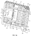
Figure 3a is an underside perspective view of a work table forming part of the convertible sawhorse and work table shown inFigure 1a . -
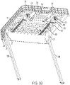
Figure 3b is an underside perspective view of the work table shown inFigure 3a from a second direction and further showing the support rods forming part of the convertible sawhorse and work table. -
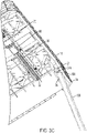
Figure 3c is a closeup underside perspective view showing a portion of the work table as shown inFigure 3b . -
Figure 3d is a closeup underside perspective view showing a portion of the work table shown as inFigure 3b . -
Figure 4a is a perspective view showing elements of the convertible sawhorse and work table shown inFigure 1a with the worktable not shown. -
Figure 4b is a side elevation view of the convertible sawhorse and work table as shown inFigure 4a . -
Figure 4c is a side elevation view of the convertible sawhorse and work table as shown inFigure 4b in the closed position. -
Figure 4d is a side elevation view of the convertible sawhorse and work table as shown inFigure 4b in the sawhorse position. -
Figure 5a is a close up side elevation view of several elements of the convertible sawhorse and work table as shown inFigure 4b . -
Figure 5b is an underside perspective view showing several elements of the convertible sawhorse and work table as shown inFigure 1a . -
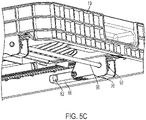
Figure 5c is a closeup underside perspective view showing several elements of the convertible sawhorse and work table as shown inFigure 1a . -
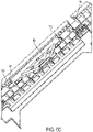
Figure 5d is an overhead perspective view of the convertible sawhorse and work table as shown inFigure 1a showing several elements thereof with the worktable not shown. -
Figure 5e is a closeup perspective view showing a portion of the top of one sawhorse leg of the convertible sawhorse and work table as shown inFigure 1a . -
Figure 6a is a closeup overhead perspective view of the convertible sawhorse and work table as shown inFigure 1a showing several elements thereof with the worktable not shown. -
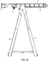
Figure 6b is a closeup side elevation view showing several elements of the convertible sawhorse and work table as shown inFigure 1a . -
Figure 6c is a closeup perspective view showing several elements of the convertible sawhorse and work table as shownFigure 6b . -
Figure 7a is a top perspective view of the push button forming part of the convertible sawhorse and work table as shown inFigure 1a . -
Figure 7b is an underside perspective view of the push button shown inFigure 7a . -
Figure 8a is a side perspective view of a first sawhorse leg forming part of the convertible sawhorse and work table as shown inFigure 1a . -
Figure 8b is an opposite side perspective view of the first sawhorse leg shown inFigure 8a . -
Figure 9a is a side perspective view of a second sawhorse leg forming part of the of the convertible sawhorse and work table as shown inFigure 1a . -
Figure 9b is an opposite side perspective view of the second sawhorse leg shown inFigure 9a . -
Figure 10 is a side perspective view of a gear forming part of the convertible sawhorse and work table as shown inFigure 1a . -
Figure 11 is a perspective view of a slider pivot pin forming part of the convertible sawhorse and work table as shown inFigure 1a . -
Figure 12 is a perspective view of a pivoting slider forming part of the convertible sawhorse and work table as shown inFigure 1a . -
Figure 13 is a perspective view of a slider base forming part of the convertible sawhorse and work table as shown inFigure 1a . -
Figure 14 is a perspective view of a pivoting support profile rod forming part of the convertible sawhorse and work table as shown inFigure 1a . -
Figure 15 is a perspective view of a cylindrical sliding rod forming part of the convertible sawhorse and work table as shown inFigure 1a . -
Figure 16 is a perspective view of a profile cap forming part of the convertible sawhorse and work table as shown inFigure 1a . -
Figure 17 is a perspective view of a gear axis rod forming part of the convertible sawhorse and work table as shown inFigure 1a . -
Figure 18a is a perspective view of a rack forming part of the convertible sawhorse and work table as shown inFigure 1a . -
Figure 18b is an overhead perspective view of the rack shown inFigure 18a . -
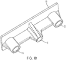
Figure 19 is a perspective view of a push button lock cover forming part of the convertible sawhorse and work table as shown inFigure 1a . -
Figure 20 is an overhead perspective view of a tray forming part of the convertible sawhorse and work table as shown inFigure 1a . -
Figure 21 is an underside perspective view a tray element forming part of the tray shown inFigure 20 . - With reference to
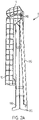
Figures 1 and2a -2e, convertible sawhorse and work table 1 is shown. Convertible sawhorse and work table 1 includesworktable 10, two pivotingsupport rods 130,first sawhorse leg 110,second sawhorse leg 120, andtray 150 disposed between firstsawhorse leg 110 andsecond sawhorse leg 120. InFigures 1 and2d , convertible sawhorse and work table 1 is in its fully open position withupper surface 12 ofworktable 10 disposed substantially horizontally and supported centrally byfirst sawhorse leg 110 andsecond sawhorse leg 120 and adjacent two corners by pivotingsupport rods 130. InFigure 2a , convertible sawhorse and work table 1 is shown in a fully collapsed position withfirst sawhorse leg 110 andsecond sawhorse leg 120 disposed adjacent each other withtray 150 collapsed and fitting therebetween so as to not be shown,worktable 10 folded againstsecond sawhorse leg 120, pivotingsupport rods 130 folded againstfirst sawhorse leg 110.Worktable 10 is locked tosecond sawhorse leg 120 viaprotrusion 125 onsecond sawhorse leg 120 fitting within lock opening 13 formed on worktable 10 (seeFigure 3a ). InFigures 2b and 2e, convertible sawhorse andworktable 1 is shown in an intermediate position withfirst sawhorse leg 110 pivoted away fromsecond sawhorse leg 120 to support the structure,tray 150 unfolded therebetween, andworktable 10 disposed adjacentsecond sawhorse leg 120. In this position,rear wall 11 ofworktable 10 is horizontally disposed and overlies the top surface offirst sawhorse leg 110, which itself overlaps the top surface ofsecond sawhorse leg 120, and the outer surface there of functions as a sawhorse surface.Figure 2c shows an intermediate position in which convertible sawhorse and work table 1 is being moved between the positions shown inFigure 2b andFigure 2d . - With further reference to
Figures 3a andFigure 3b , further details ofworktable 10 and in particular the underside thereof are disclosed.Worktable 10 includesupper work surface 12 andfront wall 19 and twoside walls 14 extending downwardly therefrom.Rear wall 11 includes a slanted upper surface, an intermediate surface angled with respect to the upper surface and a lower surface at a further angle, and as noted above the upper surface may serves as the sawhorse surface when the assembly is in the sawhorse configuration.Rack channels 22 are formed by walls extending downwardly from the lower surface in a generally longitudinal direction between from a position rearward offront wall 19 to a position forward ofrear wall 11 and are generally parallel toside walls 14 and disposed laterally inwardly thereof. Eachrack channel 22 is formed by two walls each having three square shapedslots 22b at the lower ends. Screw-threadedprojections 22a are formed on the lower surface ofworktable 10 above the location ofslots 22. Various circular and oblong slots may be formed throughworktable 10. -
Worktable 10 further includeshandle receiving portion 16 which includes an opening formed throughfront wall 19. The rear surface ofhandle receiving portion 16 includes throughchannel 16a. The lower surface ofhandle receiving portion 16 includes three throughslots 16a.Handle 15, (shown inFigures 4a ,4b and5a ) includes three protrusions which are snap fitted intoslots 16a to securehandle 15 inhandle receiving portion 16.Louvered support walls 17 extends downwardly from the lower surface ofwork surface 12 and includes two throughslots 17a.Support wall 17 along with twoside walls 17b define a generallysquare region 17c into which pushbutton 40 is received. Screw-threadedprojection 18 extends downwardly from the lower surface ofwork surface 12 behindhandle receiving portion 16 and withinregion 17c. Push button opening 20 (seeFigure 1a ) is formed throughwork surface 12 at a location abovehandle receiving portion 16. Furtherlateral walls 17d extend transversely from the laterally outward sides ofrack channels 22 to the inner surface of eachside wall 14.Lock opening 13 is which may include two spring loaded tabs is formed in the lower surface offront wall 19 belowhandle receiving portion 16. -
Worktable 10 further includesouter flanges 24 andinner flanges 26 extending downwardly fromwork surface 12 at the rear corners thereof, generally forward ofrear wall 11. Eachouter flange 24 includes a C-shapedchannel 24a and eachinner flange 26 includes C-shapedchannel 26a formed therethrough. Each of a pair ofchannels slide channel 24a/26a. As best shown inFigures 3b and3c ,cross rods 27 extend between each of a pair ofouter flange 24 andinner flange 26 at a location midway alongchannels Geometric tooth 27a extends from eachrod 27, generally rearwardly towardsrear wall 11. - With further reference to
Figures 18a and18b ,rack 30 is further disclosed.Rack 30 includeslower wall 36 andupper wall 38 withprimary wall 31 extending therebetween.Lower wall 36 extends outwardly fromprimary wall 31 to a greater extent thanupper wall 38 so as to giverack 30 an overall inverted T-shaped configuration.Rack teeth 32 are formed onlower wall 36. Strengtheningribs 35 extending betweenlower wall 36 andupper wall 38.Tabs 34 extend laterally from three ofribs 35 and include semi-circular screw openings 34a. With reference toFigures 3b and3c , racks 30 are disposed inrack channels 22 ofworktable 10 withtabs 34 fitting within square shapedslots 22b.Racks 30 are secured to worktable 10 by screws (not shown) which fit through openings 34a and into screw-threadedprojections 22a. - With reference to
Figures 7a and7b ,push button 40 is disclosed.Push button 40 includes a main body portion having acylindrical pivot axis 44 formed transversely across an upper surface at a generally midway location. Push tab orsurface 49 is formed at a forward end ofpush button 40. Throughhole 46 and raised,non-through openings 48 are formed betweenaxis 44 and pushsurface 49. Two hookedpush button teeth 42 extend from the rear ofpush button 44. With further reference toFigures 3a ,3b ,4b and5a -5c,push button 40 is disposed adjacent the lower surface ofworksurface 12 ofworktable 10 withinsquare region 17c.Push tab 49 is fitted throughchannel 16a formed inhandle receiving portion 16 and is disposed inpush button opening 20 inworktable 10. Screw threadedprojection 18 fits within throughhole 46.Teeth 42 extend throughsupport wall openings 17a.Pivot axis 44 snap fits within four semi-circular downward projections 18a formed on the lower surface ofwork surface 12 to pivotablysecure push button 40 toworktable 10. - With further reference to
Figure 19 , pushbutton lock cover 50 is disclosed.Lock cover 50 includes twohollow cylinders 52 on either side and lockcover screw column 54 centrally located therebetween. With reference toFigures 3b ,4a and5b , lock cover 50 is disposed beneathpush button 40, with lockcover screw column 54 disposed throughhole 46 and received about screw threadedprojection 18. A screw secureslock cover 50 to the lower surface ofwork surface 12 ofworktable 10, withpush button 40 disposed therebetween. Springs are secured withinhollow cylinders 52, in contact with the lower surfaces ofnon-through openings 48 ofpush button 40, to thereby biaspush button 40 upwardly forward ofaxis 44, withpush tab 49 thereby raised to an upper most location within opening 20, andteeth 42 biased downwardly. Therefore, pushingtab 49 causes pushbutton 40 to pivot aboutaxis 44 and raisesteeth 42 upwardly. - With reference to
Figures 8a and8b ,first sawhorse leg 110 is disclosed. First sawhorseleg 110 includesside leg elements upper leg element 111 andlower leg element 113 extending laterally therebetween.Upper leg element 111 includes a pair ofrack slots 116 formed adjacent and extending through the side ends approximately above or just inward ofleg elements projections 117 project intorack slots 116 at an upper open end.Openings 118 are formed on an inward surface ofupper leg element 111, at a location just belowrack slots 116. As will be discussed further below, oneslider base 60 is disposed within eachopening 118, and onesuch slider base 60 is shown inFigure 8a . Raised rearwardly hookedteeth 115 are formed in further openings ofupper leg element 111, laterally inward of and at a location above eachopening 118. Multiple circular throughhole projections 119, for example ten such projections, extend inwardly fromupper leg element 111, are spaced from each other, and extend laterally across the inner surface.Curved teeth 114 project upwardly fromlower leg element 113, are spaced from each other, and face towards a common axis in an alternating arrangement, that is, the curved outer side ofteeth 114 alternately face the forward or rearward direction relative tolower leg element 113.Side leg elements lower leg element 113 intofeet 112. Eachfoot 112 includesfoot slot 112a. Circular throughopening 112b is formed infoot 112 outwardly ofslot 112a and correspondingcircular opening 112c extends withinfoot 112 on the other side ofslot 112a. A ledge is formed behindopening 112c withfoot 112. - With reference to
Figures 9a and9b ,second sawhorse leg 120 is disclosed. Second sawhorse leg 120 includesside leg elements upper leg element 121 andlower leg element 123 extending laterally therebetween.Upper leg element 121 includes spaced extendingprojections 126 projecting from an upper surface and formingslots 126a therebetween.Curved teeth 124 project upwardly fromlower leg element 123, are spaced from each other, and face towards a common axis in an alternating arrangement, that is, the curved outer side ofteeth 124 alternately face the forward or rearward direction relative toleg element 123.Protrusion 125 extends from the outer side oflower leg element 123 at a central location just belowteeth 124.Side leg elements lower leg element 113 and extend intofeet 122. Multiple flexible column shapedprotrusions 127, for example ten such protrusions, are spaced from each other and extend laterally adjacent the top surface ofleg element 121. - With reference to
Figures 20 and21 ,tray 150 is disclosed.Tray 150 includes left and right tray portions 151 which are identical to each other. Tray portions 151 include fourtabs 153 extending from one side surface.Protrusion 153a extends downwardly from eachtab 153.Circular columns 153b extend between left and right projections extending downwardly from eachtab 153.Semi-circular columns 154 extend from the same side surface, alternating withtabs 153.Openings 155 are formed through tray portions 151 behind eachcolumn 154.Tray 150 is assembled with eachcolumn 154 pivotably disposed about onecircular column 153b, withprotrusion 153a snapped into acorresponding hole 155.Protrusions 153a move out ofholes 155 when tray portions 151 pivot from the open position to a fully closed position in which tray portions 151 are adjacent each other. Each tray portion 151 also includes spacedcolumns 152 at an opposite side fromtabs 153. - With further reference to
Figures 1 ,4a ,4b and5a ,first sawhorse leg 110 is assembled tosecond sawhorse leg 120 with the upper surface ofleg element 121 ofsecond sawhorse leg 120 fitting below an overhanging portion ofupper leg element 111 offirst sawhorse leg 110. Flexible column shapedprotrusions 127 ofsecond sawhorse 120 are snap-fitted into circular throughhole projections 119 offirst sawhorse leg 110 to pivotably secure the sawhorse legs together around an axis created throughprotrusions 127.Columns 152 oftray 150 are snap fitted intoteeth 114 offirst sawhorse leg 110 andteeth 124 ofsecond sawhorse leg 120 to pivotablysecure tray 150 to each sawhorse leg. When the sawhorse legs are pivoted to the closed position adjacent each other, trays portions 151 pivot relative to and are folded against each other and are generally received in an open space formed between the inner surfaces of each sawhorse leg. - With reference to
Figure 13 ,slider base 60 is disclosed.Slider base 60 includes flexibleslider base protrusions 62 extending from both sides thereof.Slider base 60 also includes three forward spacedprojections 64, each including circular throughhole 64a. With reference toFigures 5e and8a , oneslider base 60 is slidably disposed into one ofopenings 118 formed infirst leg 110.Rectangular windows 118a are formed in the rear of each opening 118 on either side thereof. Whenslider base 60 is slid intoopening 118,protrusions 62 snap into eachwindow 118a to secureslider base 60 therein. - With reference to
Figure 12 , pivotingslider housing 70 is disclosed.Slider housing 70 includesside walls 72 defining an open region therebetween.Ledges 76 extend from the top of eachside wall 72 partially covering the open region. Eachside wall 72 incudes a throughopening 72a at a forward end, and five spacedprojections 74 at a rearward end. Eachprojection 74 includes acircular opening 74a formed therethrough. With further reference toFigure 11 ,slider pivot pin 80 is disclosed.Pivot pin 80 includes twoflexible prongs 82 at one end each having forwardtab 82a. With further reference toFigures 3b ,5c ,5d and5e ,slider housing 70 is secured toslider base 60 by interlacingprojections 74 withprojections 64 withopenings 64a aligned withopenings 74a, and withpivot pin 80 disposed through all of the aligned openings.Prongs 82 flex outwardly withtips 82a disclosed outwardly of one ofside walls 72 to preventpin 80 from sliding laterally and thereby preventingslider housing 70 from laterally moving relative toslider base 60.Slider housing 70 is thereby secured tofirst sawhorse leg 110 adjacentupper leg element 11. However,slider housing 70 may freely pivot aboutpin 80 relative to bothslider base 60 andfirst sawhorse leg 110. - With reference to
Figure 17 , cylindricalgear axis rod 90 is disclosed. Gear axis rod includes screw-threadedopenings 90a adjacent each end. With reference toFigure 10 ,gear 92 is disclosed.Gear 92 includesgear teeth 94 disposed about a hollow central hub and hollowcircular projections 96 extending laterally from each side of the hub. One ofprojections 96 includes transverse throughholes 96a extending through both sides thereof. With reference toFigures 3b and5a -5d, onegear 92 is disposed in the open region of eachslider housing 70.Gear axis 90 is disposed through the hollow central hub andprojections 96 of eachgear 92, with screw-threadedopenings 90a disposed beneath thoughholes 96a, and a screw disposed therein to securegears 92 near both ends ofgear axis 90.Gear axis 90 also extends throughopenings 72a of both pivotingslider housings 70. - With reference to
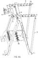
Figures 4a-6c ,worktable 10 is slidably secured tofirst sawhorse leg 110 by disposingracks 30 secured thereto inrack slots 116. Rack retainingprojections 117 are disposed above racklower wall 36 to preclude vertical motion ofracks 30 and thus worktable 10 relative tofirst sawhorse leg 110.Racks 30 are also fitted into the open regions ofpivotable slider housing 70, withledges 76 extending abovelower walls 36.Rack teeth 32 engage gears 92. Therefore,worktable 10 and all elements attached thereto includingracks 30 andpush button 40 may move laterally across the upper surface offirst sawhorse leg 110, withracks 30 sliding throughslots 116. Sinceracks 30 and gears 92 are disposed on both lateral sides ofworktable 10 and are linked bygear axis 90, any pulling or pushing force directed to only one side ofworktable 10 will automatically be transferred to the other side to ensure smooth motion. Furthermore, since pivotingslider housings 70 can pivot relative tofirst sawhorse leg 110 whenracks 30 have clearedslots 116, andslider housings 70 may pivot relative toslider bases 60,worktable 10 andhousings 70 may jointly pivot relative tofirst sawhorse leg 110. Additionally, with reference toFigures 1 ,4a ,6a and6c , when convertible sawhorse and work table 1 is in the fully open position,push button teeth 42 are disposed behind and in contact withteeth 115 offirst sawhorse leg 110. Sincepushbutton 40 is secured toworktable 10, the contact ofteeth 42 behindteeth 115 precludes lateral movement ofworktable 10 relative tofirst sawhorse leg 110, locking convertible sawhorse and work table 1 in the fully open position. By pushing onpush tab 49 against the upward spring bias and thereby pivotingpushbutton 40 about itsaxis 44,teeth 42 are raised to clearteeth 115, andworktable 10 can be moved laterally forward relative tofirst sawhorse leg 110 and out of the fully opened position. - With reference to
Figure 14 , pivotingsupport rod 130 is disclosed. Pivotingsupport rod 130 includes circular throughopenings 132 formed through and near a lower end thereof and circular throughopenings 134 formed through and near an upper end thereof, and rectangular throughopening 136 formed adjacent and belowopening 134. With reference toFigure 16 ,profile cap 140 is disclosed.Profile cap 140 is substantially hollow and is defined by fourside walls 145 andupper surface 141. Circular through hole 141a is formed throughsurface 141. Circular throughholes 145a are formed through two opposite side surfaces 145. Oneprofile cap 140 is disposed through the lower open end of eachsupport rod 130, with throughholes 145a aligned withcircular openings 132. Asecond profile pad 140 is disposed in the upper end of eachsupport rod 130 with throughholes 145a aligned withcircular openings 134. - With reference to
Figure 15 , cylindrical slidingrod 142 is disclosed and includes screw-threadedopening 142a formed therethrough. - With further reference to
Figures 4a ,4b ,8b and14 , one pivotingsupport rod 130 is disposed on eachfoot 112 offirst sawhorse 110. In particular, the lower surface ofsupport rod 130 havingprofile pad 140 disposed therein is inserted intofoot slot 112a, withcircular openings 132 aligned withcircular openings Slider pivot pin 80 is disposed throughopenings 112b,openings 132 andholes 145a, withprongs 82 extending intocircular opening 112c.Prongs 82 flex outwardly to securetabs 82a behind a ledge formed withinopenings 112c to retainsupport rod 130 onfirst sawhorse leg 110, while allowing pivoting movement ofsupport rod 130 about an axis defined bypin 80 towards and away fromfirst sawhorse leg 110. - With further reference to
Figures 2a ,3d ,14 and15 , the manner in which the upper ends ofsupport rods 130 are secured toworktable 110 is disclosed. Asecond profile pad 140 is disclosed in the upper open end ofsupport rod 130, with thoughholes 145 aligned withopenings 134. Cylindrical slidingrod 142 is disposed throughhole 145 andopenings 134 so as to include ends extending outwardly from either side ofsupport rod 130. A screw is inserted throughopening 141b ofpad 140 and is screwed into the threadedopenings 142a ofrod 140 to secure bothpad 140 androd 142 relative to supportrod 130. The upper end ofsupport rod 130 is disposed between each pair ofinner flange 26 andouter flange 24, with one end ofrod 142 extending throughchannel 26a and the opposite end extending though channel 26b. Therefore, the upper end ofsupport rods 130 can be moved from a location adjacent the upper end ofchannels 24a/26a to a location adjacent the lower end, with the outer ends ofrod 42 sliding in the channels. When the upper end ofsupports rods 130 are located at the upper end of thechannels 24a/26a,geometric tooth 27a is disposed in rectangular throughopening 136. - With reference to
Figures 1 , 2a-2e and 4a-4d, the operation of convertible sawhorse and work table 1 is further explained. InFigures 2a and4c , convertible sawhorse and work table 1 is in the closed position. Worktable 10 andracks 30 secured thereto are pivoted downward so as to extend adjacent and generally parallel tosecond sawhorse leg 120. Similarly,slider 70 is pivoted downwardly aboutpivot pin 80 relative toslider base 60, which is secured withinfirst sawhorse leg 110, such thatslider 70 also extends downwardly generally adjacent and generally parallel tosecond sawhorse leg 120. Slidingrod 142 is in a hooked part ofchannel 24a/26a. Sinceracks 30 andsliders 70 both pivot, gears 92 remain in contact withrack teeth 32. - With reference to
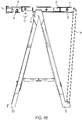
Figures 2b and4d ,first sawhorse leg 110 andsecond sawhorse leg 120 are pivoted away from each other to their fully open position relative to each other. Convertible sawhorse and work table 1 is now in the sawhorse position.Rear wall 11 ofworktable 10 is now the upper most surface of the assembly and serves as the sawhorse upper surface. Slidingrod 142 has moved out of the hooked part ofchannel 24a/26a. The configuration ofworktable 10,rack 30 andslider 70 relative tosecond sawhorse leg 120 has not changed, that is, they extend generally parallel and adjacent thereto.Tray 150 has pivoted to the fully open position.Geometric teeth 27a ofcross rods 27 extend substantially parallel to the forward walls of pivotingsupport rods 130. - With reference to
Figure 2c ,worktable 110 has been pivoted in the clockwise direction about slidingrod 142, away fromsecond sawhorse leg 120 and is now disposed substantially horizontally abovefirst sawhorse leg 110.Slider 70 has pivoted relative toslider housing 60 aboutpivot pin 80 and remains extending substantially parallel toworktable 110. The pivoting ofworktable 10 relative to the upper surface offirst sawhorse leg 110 has caused slidingrod 142 to slide alongchannel 24a/26a to an intermediate position. The pivoting ofworktable 110 also causesgeometric teeth 27a ofcross rods 27 to pivot to a position where they extend substantially perpendicular the forward walls ofsupport rods 130 but are spaced therefrom. - With reference to
Figures 1a ,2d and4b ,worktable 10 has been slid rearwardly (to the right in the Figures) to the fully open position. During rearwardmotion rack teeth 32 engagegears 92 linked bygear axis 90 to ensure that thatside walls 14 ofworktable 10 move evenly with respect to each other such that the worktable always stays square relative to the top offirst sawhorse leg 110, that is,side walls 14 ofworktable 10 remain parallel to the sides of the upper firstsaw horse leg 110. Rearward movement ofworktable 10 relative tosawhorse leg 110forces sliding rod 142 to slide upwardly inchannel 24a/26a to the uppermost end of the channel, at which point further rearward motion ofworktable 10 is precluded. With reference toFigure 1b ,support wall 17 andside walls 17d ofworktable 10 also contact the forward surface ofupper leg element 111 to also preclude further rearward motion ofworktable 10.Pivot support rods 130 pivot about pivot pins 80 infeet 112 to a position in which they are spaced fromfirst sawhorse leg 110, and which is slightly past vertical. With reference toFigures 3c and3d ,geometric teeth 27a ofcross rods 27 are also moved rearwardly and lodge withinrectangular openings 136 of pivotingsupport rods 130, which precludes upward movement ofrear wall 11 of table 110 at the locations ofsupport rods 130.Projections 117 inrack slots 116 preclude upward movement ofworktable 110. With further reference toFigures 6a and6c ,teeth 42 ofpushbutton 40 lodge behind raisedteeth 115 offirst sawhorse leg 110 to preclude forward movement ofworktable 110 relative thereto, and convertible sawhorse and work table 1 is locked in the worktable position. - To close convertible sawhorse and work table 1, push
tab 49 is pushed to pivotpush button 40 to removeteeth 42 from behind raisedteeth 115. Work table 110 can be moved forwardly to causegeometric teeth 27a to move out ofrectangular openings 136. Slidingrod 142 moves downwardly inchannel 24a/26a until the position shown inFigure 2c is reached.Worktable 10 is then pivoted downwardly towardssecond sawhorse leg 120 to the sawhorse position shown inFigure 2b in which worktable 110 is locked tosawhorse leg 120. First sawhorseleg 110 andsecond sawhorse leg 120 are then pivoted relative to each other to achieve the closed position ofFigure 2a .
Claims (10)
- An assembly comprising:a sawhorse including first and second sawhorse legs (110, 120) pivotably connected to each other at one end thereof to define an upper end of said sawhorse, said first and second sawhorse legs pivotable relative to each other between a closed sawhorse position in which said first and second sawhorse legs are folded substantially against each other and an open sawhorse position in which said first and second sawhorse legs are spaced apart from each other below said upper end;a worktable (10) defining first and second worktable sides;a first rack (30) and a second rack (30) on a lower surface of said worktable;a first gear (92) disposed in engagement with said first rack and a second gear (92) disposed in engagement with said second rack;a gear axis rod (90) extending between and engaged with said first gear and said second gear; characterized bya support rod (130) pivotably secured adjacent one end thereof to said first sawhorse leg and pivotably secured adjacent a second end thereof to said worktable; wherein,in a first condition of said assembly, said sawhorse is in the closed sawhorse position, said worktable is disposed outwardly adjacent of said second sawhorse leg and said support rod is disposed outwardly adjacent of said first sawhorse leg, and wherein,said assembly may be moved to a second condition in which said sawhorse is in the open sawhorse position, said worktable is disposed substantially horizontally and is supported at an inward location thereof by said upper end of said sawhorse and said worktable is supported adjacent an end thereof by said support rod, said worktable sliding above the upper end of said sawhorse during at least a portion of the movement between the first and second conditions with said racks causing rotation of said gears.
- The assembly recited in claim 1, wherein, said assembly may be moved to a third condition in which said sawhorse is in the open sawhorse position and said worktable (10) is disposed outwardly adjacent of said second sawhorse leg (120) and said support rod (130) is disposed outwardly adjacent of said first sawhorse leg (110), said worktable further defining a rear side extending between said first and second worktable sides, said rear side covering the upper end of said sawhorse and thereby defining the upper surface of said sawhorse in the third condition.
- The assembly recited in claim 2, further comprising a first slider housing (70) and a second slider housing (70) each defining an interior region therein, said first gear (92) and said first rack (30) disposed within said first slider housing interior region and said second gear (92) and said second rack (30) disposed with said second slider housing interior region, said first and second slider housings pivotably secured on said first sawhorse leg (110).
- The assembly recited in claim 3 further comprising a first slider base (60) and a second slider (60) base fixedly secured to said first sawhorse leg (110), said first slider housing (70) pivotably secured to said first slider base and said second slider housing (70) pivotably secured to said second slider base.
- The assembly recited in claim 1 further comprising a push button (40) secured to said work table (10), said push button comprising a push tab (49) and a push button tooth (42), said first sawhorse leg (110) comprising a tooth (115), wherein, in the second condition of said assembly said push button tooth is disposed behind and in engagement with said first sawhorse leg tooth to preclude relative sliding movement of said work table relative to said first sawhorse leg, wherein, when said push tab is pushed said push button tooth is removed from engagement with said first sawhorse leg tooth to allow relative sliding movement of said work table relative to said first sawhorse leg.
- The assembly recited in claim 1, said work table including inner flange (26) and outer flange (24) extending from a corner thereof, said flanges each defining a channel therethrough, said support rod (130) including a sliding rod (142) disposed therethrough adjacent one end, said sliding rod having first and second ends disposed outwardly of said support rods, said first end of said sliding rod disposed in said first flange channel and said second end of said sliding disposed in said second flange channel, said sliding rod sliding in said channels when said work table is moved between the assembly conditions.
- The assembly recited in claim 6, said work table further including a cross rod (27) extending between said inner and outer flanges (26, 24), said cross rod including a geometric tooth (27a) extending therefrom, said support rod (130) including an opening formed adjacent said one end thereof, wherein, when said assembly is in the second condition, said geometric tooth extends into said support rod opening to secure said work table (10) against being moved vertically relative to said sawhorse legs (110, 120).
- An assembly comprising:a sawhorse including a first sawhorse leg (110) and a second sawhorse leg (120) pivotably connected to each other at the upper ends thereof, said sawhorse legs including sawhorse feet (80) at the lower ends thereof; a worktable having a first rack (30) and a second rack (30) disposed on said lower surface;a first gear (92) disposed in engagement with said first rack and a second gear disposed in engagement with said second rack; anda gear axis rod (90) extending between and engaged with said first gear and said second gear;characterized by two pivot support rods (130), each said support rod pivotably mounted at a lower end thereof to the feet of said first sawhorse leg and having a sliding rod (142) disposed therethrough adjacent an upper end thereof;said worktable (10) having a lower surface and two pairs of flanges, each of said pair of flanges (24, 26) disposed at a corner of the worktable, each said flange having a channel formed therethrough, one of said sliding rods slidably disposed at either end thereof in one channel of one flange of a pair of flanges.
- The assembly recited in claim 8 further comprising a first slider housing (70) and a second slider housing (70) each defining an interior region therein, said first gear (92) and said first rack (30) disposed within said first slider housing interior region and said second gear (92) and said second rack (30) disposed with said second slider housing interior region, said first and second slider housings pivotably secured on said first sawhorse leg.
- The assembly recited in claim 8 further comprising a first slider base (60) and a second slider base (60) fixedly secured to said first sawhorse leg (110), said first slider housing (70) pivotably secured to said first slider base and said second slider housing (70) pivotably secured to said second slider base.
Applications Claiming Priority (1)
| Application Number | Priority Date | Filing Date | Title |
|---|---|---|---|
| US201962887848P | 2019-08-16 | 2019-08-16 |
Publications (2)
| Publication Number | Publication Date |
|---|---|
| EP3778135A1 EP3778135A1 (en) | 2021-02-17 |
| EP3778135B1 true EP3778135B1 (en) | 2022-04-27 |
Family
ID=72087911
Family Applications (1)
| Application Number | Title | Priority Date | Filing Date |
|---|---|---|---|
| EP20191053.6A Active EP3778135B1 (en) | 2019-08-16 | 2020-08-14 | Convertible sawhorse and work table |
Country Status (2)
| Country | Link |
|---|---|
| US (3) | US11597074B2 (en) |
| EP (1) | EP3778135B1 (en) |
Families Citing this family (7)
| Publication number | Priority date | Publication date | Assignee | Title |
|---|---|---|---|---|
| US11426856B2 (en) * | 2018-08-03 | 2022-08-30 | The Stanley Works Israel Ltd. | Convertible sawhorse and worktable |
| US11597074B2 (en) * | 2019-08-16 | 2023-03-07 | The Stanley Works Israel Ltd. | Convertible sawhorse and worktable |
| CN211333078U (en) * | 2019-10-09 | 2020-08-25 | 金华市渤蓝科技有限公司 | Multifunctional workbench |
| CN114348236B (en) * | 2021-12-31 | 2023-06-06 | 哈瓦国际航空技术(深圳)有限公司 | Folding mechanism and unmanned aerial vehicle |
| US11745328B1 (en) | 2022-02-23 | 2023-09-05 | Ronald Evenson, Jr. | Sawhorse support attachment device |
| CN115008427A (en) * | 2022-06-28 | 2022-09-06 | 久维科技(苏州)有限公司 | workbench |
| CN118752454B (en) * | 2024-09-06 | 2024-12-24 | 金华市亚虎工具有限公司 | Multi-mode slip controller |
Family Cites Families (47)
| Publication number | Priority date | Publication date | Assignee | Title |
|---|---|---|---|---|
| US4154435A (en) * | 1978-02-22 | 1979-05-15 | The Black And Decker Manufacturing Company | Portable workbench |
| GB2028642B (en) | 1978-07-07 | 1983-03-30 | Ai Ko Britain Ltd | Workbench |
| FR2554754B3 (en) * | 1983-11-10 | 1986-05-23 | Guilhot Gilbert | DEVICE FOR POSITIONING THE COMPONENTS OF A HANDLING PALLET DURING MANUFACTURE |
| US5020799A (en) * | 1988-08-09 | 1991-06-04 | Chang Yong Hong | Folding billiard table |
| US4943040A (en) * | 1989-01-26 | 1990-07-24 | Cannon Equipment Company | Adjustable work stand |
| US4909491A (en) * | 1989-02-08 | 1990-03-20 | Cheng Wen H | Saw platform and workbench |
| NL9301519A (en) * | 1993-09-02 | 1995-04-03 | Lawn Comfort Sa | Foldable table. |
| US5535847A (en) | 1994-04-06 | 1996-07-16 | Storehorse, Inc. | Table top attachment for sawhorses |
| US5560448A (en) | 1995-01-03 | 1996-10-01 | Zag Ltd. | Folding sawhorse |
| US5735220A (en) | 1996-12-16 | 1998-04-07 | Wang; Ming-Cheng | Slide rails of extensible table |
| US5924684A (en) * | 1997-10-21 | 1999-07-20 | Cheng; Wen-He | Worktable |
| IL124680A (en) * | 1998-05-27 | 2001-12-23 | Keter Plastic Ltd | Folding sawhorse |
| US6286824B1 (en) | 1999-11-01 | 2001-09-11 | Keter Plastic Ltd. | Collapsible worktable |
| TW435319U (en) | 2000-03-14 | 2001-05-16 | Ke Chuan Ming | Fast positioning and clamping worktable structure |
| US6659440B2 (en) * | 2000-12-18 | 2003-12-09 | Zag Industries Ltd. | Portable support assembly for a workpiece |
| US6712180B2 (en) | 2002-03-01 | 2004-03-30 | Zag Industries Ltd. | Height adjustable sawhorse |
| US6769674B2 (en) * | 2002-05-15 | 2004-08-03 | Huei-Yu Chang | Foldable workbench |
| US6942229B2 (en) | 2003-10-31 | 2005-09-13 | One World Technologies Limited | Collapsible stand for a bench-top power tool |
| US20050230188A1 (en) | 2004-04-19 | 2005-10-20 | Berg Joel J | Saw horse with adjustable height and length top rail |
| US7588255B2 (en) * | 2004-11-10 | 2009-09-15 | Zag Industries, Ltd. | Collapsible clamping work table |
| US20070175368A1 (en) | 2006-01-31 | 2007-08-02 | Yoder Ervin E | Leaf table having lockable slide rails |
| US7631604B2 (en) | 2006-05-08 | 2009-12-15 | Tsung-Chieh Huang | Telescopic and foldable table |
| US20090288914A1 (en) | 2008-05-22 | 2009-11-26 | Zag Industries, Ltd. | Sawhorse |
| CN101554722A (en) | 2009-05-20 | 2009-10-14 | 温海腾 | Foldable workbench |
| US8656527B2 (en) | 2011-06-16 | 2014-02-25 | Furniture of America, Inc. | Multifunctional furniture |
| US9055821B2 (en) | 2011-06-16 | 2015-06-16 | Furniture of America, Inc. | Multifunctional furniture |
| EP2599595B1 (en) | 2011-12-01 | 2017-10-11 | The Stanley Works Israel Ltd. | Adjustable sawhorse |
| EP2767368B1 (en) * | 2013-02-15 | 2016-02-10 | The Stanley Works Israel Ltd. | Work bench including a vise |
| EP2767369B1 (en) | 2013-02-15 | 2016-04-20 | The Stanley Works Israel Ltd. | Work bench frame |
| CN204273631U (en) | 2014-11-19 | 2015-04-22 | 厦门新技术集成有限公司 | A kind of same table |
| CA2918977A1 (en) | 2015-01-29 | 2016-07-29 | Creative Plastic Concepts, Llc | Sawhorse shelf hinge feature |
| CN107405768A (en) | 2015-02-03 | 2017-11-28 | 亲和工具工程有限公司 | With can Automatic-expanding leg tool rack |
| US9889553B2 (en) | 2015-02-04 | 2018-02-13 | Affinity Tool Works, Llc | Collapsible mobile work bench and tool support stand |
| US10550638B2 (en) | 2015-11-09 | 2020-02-04 | Louisville Ladder Inc. | Stepladder adapted for use as a single ladder or an extension ladder |
| EP3374114B1 (en) * | 2015-11-11 | 2023-01-04 | The Stanley Works Israel Ltd. | Workbench |
| US10675749B2 (en) | 2015-12-18 | 2020-06-09 | Creative Plastic Concepts, Llc | Keyed rail and support surface for saw horse |
| US20180163471A1 (en) | 2016-12-12 | 2018-06-14 | Tek Lentine | Pinch Flex Latch, Ladder and Method |
| US10435947B2 (en) | 2016-12-12 | 2019-10-08 | Werner Co. | Ladder with pinch flex latch, and method |
| US10092089B1 (en) * | 2017-06-06 | 2018-10-09 | Chung Chiao Holding Corp. | Height-adjustable table |
| US10426259B2 (en) * | 2017-08-08 | 2019-10-01 | Varidesk, Llc | Adjustable height table |
| WO2019057216A1 (en) | 2017-09-22 | 2019-03-28 | 苏州宝时得电动工具有限公司 | Workbench |
| US10864625B2 (en) * | 2017-12-05 | 2020-12-15 | Js Products, Inc. | Sawhorse |
| CN208084294U (en) | 2018-04-01 | 2018-11-13 | 金华市亚虎工具有限公司 | A kind of twofold workbench |
| CN208451788U (en) | 2018-04-01 | 2019-02-01 | 金华市亚虎工具有限公司 | Twofold multifunctional workstation |
| CN108582268B (en) | 2018-04-01 | 2023-02-10 | 金华市亚虎工具有限公司 | Double-folding multifunctional workbench |
| US11426856B2 (en) * | 2018-08-03 | 2022-08-30 | The Stanley Works Israel Ltd. | Convertible sawhorse and worktable |
| US11597074B2 (en) * | 2019-08-16 | 2023-03-07 | The Stanley Works Israel Ltd. | Convertible sawhorse and worktable |
-
2020
- 2020-08-06 US US16/986,630 patent/US11597074B2/en active Active
- 2020-08-14 EP EP20191053.6A patent/EP3778135B1/en active Active
-
2023
- 2023-03-02 US US18/116,459 patent/US12017338B2/en active Active
-
2024
- 2024-05-17 US US18/667,540 patent/US20240300086A1/en active Pending
Also Published As
| Publication number | Publication date |
|---|---|
| US11597074B2 (en) | 2023-03-07 |
| US12017338B2 (en) | 2024-06-25 |
| US20210046634A1 (en) | 2021-02-18 |
| EP3778135A1 (en) | 2021-02-17 |
| US20230202023A1 (en) | 2023-06-29 |
| US20240300086A1 (en) | 2024-09-12 |
Similar Documents
| Publication | Publication Date | Title |
|---|---|---|
| EP3778135A1 (en) | Convertible sawhorse and work table | |
| EP2251155B1 (en) | Folding sawhorse | |
| JP6630290B2 (en) | Furniture support frame | |
| US8534737B2 (en) | Trunk of a motor vehicle | |
| US8070226B2 (en) | Infant car seat base | |
| EP2603365B1 (en) | Guard systems for table saw | |
| CN103128803B (en) | Adjustable sawhorse | |
| US10702063B2 (en) | Frame for a drawer | |
| US10034538B1 (en) | Height-adjustable work surface assembly | |
| US9254565B1 (en) | Toolbox | |
| WO2019032697A1 (en) | Adjustable height table | |
| CN220415230U (en) | Folding pedal ladder | |
| KR102314062B1 (en) | Under rail guide bracket for drawer | |
| JP6643003B2 (en) | Telescopic leg device | |
| JPH11342027A (en) | Top plate elevating and lowering device for furniture | |
| EP1163862B1 (en) | Leg for a piece of furniture or the like, as well as a piece of furniture | |
| US20050126718A1 (en) | Carrier-positioning device for a vertical blind | |
| JP4577764B2 (en) | Assembled plastic container | |
| TWI702900B (en) | Cabinet and slide rail kit thereof | |
| JPH09262136A (en) | Top plate elevator device for furniture | |
| JP4000416B2 (en) | Telescopic scaffold board | |
| US20250197059A1 (en) | Dual latching adaptor | |
| TWI739434B (en) | Cabinet and slide rail kit thereof | |
| DE20119626U1 (en) | Lock for securing objects against unintentional relocation | |
| KR20230152304A (en) | Frame connection module and structure comprising the same |
Legal Events
| Date | Code | Title | Description |
|---|---|---|---|
| PUAI | Public reference made under article 153(3) epc to a published international application that has entered the european phase |
Free format text: ORIGINAL CODE: 0009012 |
|
| STAA | Information on the status of an ep patent application or granted ep patent |
Free format text: STATUS: THE APPLICATION HAS BEEN PUBLISHED |
|
| AK | Designated contracting states |
Kind code of ref document: A1 Designated state(s): AL AT BE BG CH CY CZ DE DK EE ES FI FR GB GR HR HU IE IS IT LI LT LU LV MC MK MT NL NO PL PT RO RS SE SI SK SM TR |
|
| AX | Request for extension of the european patent |
Extension state: BA ME |
|
| RIN1 | Information on inventor provided before grant (corrected) |
Inventor name: WAISSENGREEN, OHAD Inventor name: SHECHTMAN, VICTORIA |
|
| STAA | Information on the status of an ep patent application or granted ep patent |
Free format text: STATUS: REQUEST FOR EXAMINATION WAS MADE |
|
| 17P | Request for examination filed |
Effective date: 20210803 |
|
| RBV | Designated contracting states (corrected) |
Designated state(s): AL AT BE BG CH CY CZ DE DK EE ES FI FR GB GR HR HU IE IS IT LI LT LU LV MC MK MT NL NO PL PT RO RS SE SI SK SM TR |
|
| GRAP | Despatch of communication of intention to grant a patent |
Free format text: ORIGINAL CODE: EPIDOSNIGR1 |
|
| STAA | Information on the status of an ep patent application or granted ep patent |
Free format text: STATUS: GRANT OF PATENT IS INTENDED |
|
| RIC1 | Information provided on ipc code assigned before grant |
Ipc: B25H 1/06 20060101ALI20211209BHEP Ipc: B25H 1/04 20060101AFI20211209BHEP |
|
| INTG | Intention to grant announced |
Effective date: 20211223 |
|
| GRAS | Grant fee paid |
Free format text: ORIGINAL CODE: EPIDOSNIGR3 |
|
| GRAA | (expected) grant |
Free format text: ORIGINAL CODE: 0009210 |
|
| STAA | Information on the status of an ep patent application or granted ep patent |
Free format text: STATUS: THE PATENT HAS BEEN GRANTED |
|
| AK | Designated contracting states |
Kind code of ref document: B1 Designated state(s): AL AT BE BG CH CY CZ DE DK EE ES FI FR GB GR HR HU IE IS IT LI LT LU LV MC MK MT NL NO PL PT RO RS SE SI SK SM TR |
|
| REG | Reference to a national code |
Ref country code: GB Ref legal event code: FG4D |
|
| REG | Reference to a national code |
Ref country code: CH Ref legal event code: EP |
|
| REG | Reference to a national code |
Ref country code: AT Ref legal event code: REF Ref document number: 1486577 Country of ref document: AT Kind code of ref document: T Effective date: 20220515 |
|
| REG | Reference to a national code |
Ref country code: DE Ref legal event code: R096 Ref document number: 602020002829 Country of ref document: DE |
|
| REG | Reference to a national code |
Ref country code: IE Ref legal event code: FG4D |
|
| REG | Reference to a national code |
Ref country code: LT Ref legal event code: MG9D |
|
| REG | Reference to a national code |
Ref country code: NL Ref legal event code: MP Effective date: 20220427 |
|
| REG | Reference to a national code |
Ref country code: AT Ref legal event code: MK05 Ref document number: 1486577 Country of ref document: AT Kind code of ref document: T Effective date: 20220427 |
|
| PG25 | Lapsed in a contracting state [announced via postgrant information from national office to epo] |
Ref country code: NL Free format text: LAPSE BECAUSE OF FAILURE TO SUBMIT A TRANSLATION OF THE DESCRIPTION OR TO PAY THE FEE WITHIN THE PRESCRIBED TIME-LIMIT Effective date: 20220427 |
|
| PG25 | Lapsed in a contracting state [announced via postgrant information from national office to epo] |
Ref country code: SE Free format text: LAPSE BECAUSE OF FAILURE TO SUBMIT A TRANSLATION OF THE DESCRIPTION OR TO PAY THE FEE WITHIN THE PRESCRIBED TIME-LIMIT Effective date: 20220427 Ref country code: PT Free format text: LAPSE BECAUSE OF FAILURE TO SUBMIT A TRANSLATION OF THE DESCRIPTION OR TO PAY THE FEE WITHIN THE PRESCRIBED TIME-LIMIT Effective date: 20220829 Ref country code: NO Free format text: LAPSE BECAUSE OF FAILURE TO SUBMIT A TRANSLATION OF THE DESCRIPTION OR TO PAY THE FEE WITHIN THE PRESCRIBED TIME-LIMIT Effective date: 20220727 Ref country code: LT Free format text: LAPSE BECAUSE OF FAILURE TO SUBMIT A TRANSLATION OF THE DESCRIPTION OR TO PAY THE FEE WITHIN THE PRESCRIBED TIME-LIMIT Effective date: 20220427 Ref country code: HR Free format text: LAPSE BECAUSE OF FAILURE TO SUBMIT A TRANSLATION OF THE DESCRIPTION OR TO PAY THE FEE WITHIN THE PRESCRIBED TIME-LIMIT Effective date: 20220427 Ref country code: GR Free format text: LAPSE BECAUSE OF FAILURE TO SUBMIT A TRANSLATION OF THE DESCRIPTION OR TO PAY THE FEE WITHIN THE PRESCRIBED TIME-LIMIT Effective date: 20220728 Ref country code: FI Free format text: LAPSE BECAUSE OF FAILURE TO SUBMIT A TRANSLATION OF THE DESCRIPTION OR TO PAY THE FEE WITHIN THE PRESCRIBED TIME-LIMIT Effective date: 20220427 Ref country code: BG Free format text: LAPSE BECAUSE OF FAILURE TO SUBMIT A TRANSLATION OF THE DESCRIPTION OR TO PAY THE FEE WITHIN THE PRESCRIBED TIME-LIMIT Effective date: 20220727 Ref country code: AT Free format text: LAPSE BECAUSE OF FAILURE TO SUBMIT A TRANSLATION OF THE DESCRIPTION OR TO PAY THE FEE WITHIN THE PRESCRIBED TIME-LIMIT Effective date: 20220427 |
|
| PG25 | Lapsed in a contracting state [announced via postgrant information from national office to epo] |
Ref country code: RS Free format text: LAPSE BECAUSE OF FAILURE TO SUBMIT A TRANSLATION OF THE DESCRIPTION OR TO PAY THE FEE WITHIN THE PRESCRIBED TIME-LIMIT Effective date: 20220427 Ref country code: PL Free format text: LAPSE BECAUSE OF FAILURE TO SUBMIT A TRANSLATION OF THE DESCRIPTION OR TO PAY THE FEE WITHIN THE PRESCRIBED TIME-LIMIT Effective date: 20220427 Ref country code: LV Free format text: LAPSE BECAUSE OF FAILURE TO SUBMIT A TRANSLATION OF THE DESCRIPTION OR TO PAY THE FEE WITHIN THE PRESCRIBED TIME-LIMIT Effective date: 20220427 Ref country code: IS Free format text: LAPSE BECAUSE OF FAILURE TO SUBMIT A TRANSLATION OF THE DESCRIPTION OR TO PAY THE FEE WITHIN THE PRESCRIBED TIME-LIMIT Effective date: 20220827 |
|
| REG | Reference to a national code |
Ref country code: DE Ref legal event code: R097 Ref document number: 602020002829 Country of ref document: DE |
|
| PG25 | Lapsed in a contracting state [announced via postgrant information from national office to epo] |
Ref country code: SM Free format text: LAPSE BECAUSE OF FAILURE TO SUBMIT A TRANSLATION OF THE DESCRIPTION OR TO PAY THE FEE WITHIN THE PRESCRIBED TIME-LIMIT Effective date: 20220427 Ref country code: SK Free format text: LAPSE BECAUSE OF FAILURE TO SUBMIT A TRANSLATION OF THE DESCRIPTION OR TO PAY THE FEE WITHIN THE PRESCRIBED TIME-LIMIT Effective date: 20220427 Ref country code: RO Free format text: LAPSE BECAUSE OF FAILURE TO SUBMIT A TRANSLATION OF THE DESCRIPTION OR TO PAY THE FEE WITHIN THE PRESCRIBED TIME-LIMIT Effective date: 20220427 Ref country code: ES Free format text: LAPSE BECAUSE OF FAILURE TO SUBMIT A TRANSLATION OF THE DESCRIPTION OR TO PAY THE FEE WITHIN THE PRESCRIBED TIME-LIMIT Effective date: 20220427 Ref country code: EE Free format text: LAPSE BECAUSE OF FAILURE TO SUBMIT A TRANSLATION OF THE DESCRIPTION OR TO PAY THE FEE WITHIN THE PRESCRIBED TIME-LIMIT Effective date: 20220427 Ref country code: DK Free format text: LAPSE BECAUSE OF FAILURE TO SUBMIT A TRANSLATION OF THE DESCRIPTION OR TO PAY THE FEE WITHIN THE PRESCRIBED TIME-LIMIT Effective date: 20220427 Ref country code: CZ Free format text: LAPSE BECAUSE OF FAILURE TO SUBMIT A TRANSLATION OF THE DESCRIPTION OR TO PAY THE FEE WITHIN THE PRESCRIBED TIME-LIMIT Effective date: 20220427 |
|
| PLBE | No opposition filed within time limit |
Free format text: ORIGINAL CODE: 0009261 |
|
| STAA | Information on the status of an ep patent application or granted ep patent |
Free format text: STATUS: NO OPPOSITION FILED WITHIN TIME LIMIT |
|
| PG25 | Lapsed in a contracting state [announced via postgrant information from national office to epo] |
Ref country code: MC Free format text: LAPSE BECAUSE OF FAILURE TO SUBMIT A TRANSLATION OF THE DESCRIPTION OR TO PAY THE FEE WITHIN THE PRESCRIBED TIME-LIMIT Effective date: 20220427 Ref country code: AL Free format text: LAPSE BECAUSE OF FAILURE TO SUBMIT A TRANSLATION OF THE DESCRIPTION OR TO PAY THE FEE WITHIN THE PRESCRIBED TIME-LIMIT Effective date: 20220427 |
|
| 26N | No opposition filed |
Effective date: 20230130 |
|
| PG25 | Lapsed in a contracting state [announced via postgrant information from national office to epo] |
Ref country code: LU Free format text: LAPSE BECAUSE OF NON-PAYMENT OF DUE FEES Effective date: 20220814 |
|
| REG | Reference to a national code |
Ref country code: BE Ref legal event code: MM Effective date: 20220831 |
|
| PG25 | Lapsed in a contracting state [announced via postgrant information from national office to epo] |
Ref country code: SI Free format text: LAPSE BECAUSE OF FAILURE TO SUBMIT A TRANSLATION OF THE DESCRIPTION OR TO PAY THE FEE WITHIN THE PRESCRIBED TIME-LIMIT Effective date: 20220427 |
|
| PG25 | Lapsed in a contracting state [announced via postgrant information from national office to epo] |
Ref country code: IE Free format text: LAPSE BECAUSE OF NON-PAYMENT OF DUE FEES Effective date: 20220814 Ref country code: FR Free format text: LAPSE BECAUSE OF NON-PAYMENT OF DUE FEES Effective date: 20220831 |
|
| PG25 | Lapsed in a contracting state [announced via postgrant information from national office to epo] |
Ref country code: BE Free format text: LAPSE BECAUSE OF NON-PAYMENT OF DUE FEES Effective date: 20220831 |
|
| PG25 | Lapsed in a contracting state [announced via postgrant information from national office to epo] |
Ref country code: IT Free format text: LAPSE BECAUSE OF FAILURE TO SUBMIT A TRANSLATION OF THE DESCRIPTION OR TO PAY THE FEE WITHIN THE PRESCRIBED TIME-LIMIT Effective date: 20220427 |
|
| REG | Reference to a national code |
Ref country code: CH Ref legal event code: PL |
|
| PG25 | Lapsed in a contracting state [announced via postgrant information from national office to epo] |
Ref country code: CY Free format text: LAPSE BECAUSE OF FAILURE TO SUBMIT A TRANSLATION OF THE DESCRIPTION OR TO PAY THE FEE WITHIN THE PRESCRIBED TIME-LIMIT Effective date: 20220427 Ref country code: CH Free format text: LAPSE BECAUSE OF NON-PAYMENT OF DUE FEES Effective date: 20230831 |
|
| PG25 | Lapsed in a contracting state [announced via postgrant information from national office to epo] |
Ref country code: MK Free format text: LAPSE BECAUSE OF FAILURE TO SUBMIT A TRANSLATION OF THE DESCRIPTION OR TO PAY THE FEE WITHIN THE PRESCRIBED TIME-LIMIT Effective date: 20220427 Ref country code: HU Free format text: LAPSE BECAUSE OF FAILURE TO SUBMIT A TRANSLATION OF THE DESCRIPTION OR TO PAY THE FEE WITHIN THE PRESCRIBED TIME-LIMIT; INVALID AB INITIO Effective date: 20200814 |
|
| PG25 | Lapsed in a contracting state [announced via postgrant information from national office to epo] |
Ref country code: TR Free format text: LAPSE BECAUSE OF FAILURE TO SUBMIT A TRANSLATION OF THE DESCRIPTION OR TO PAY THE FEE WITHIN THE PRESCRIBED TIME-LIMIT Effective date: 20220427 |
|
| PG25 | Lapsed in a contracting state [announced via postgrant information from national office to epo] |
Ref country code: MT Free format text: LAPSE BECAUSE OF FAILURE TO SUBMIT A TRANSLATION OF THE DESCRIPTION OR TO PAY THE FEE WITHIN THE PRESCRIBED TIME-LIMIT Effective date: 20220427 |
|
| PG25 | Lapsed in a contracting state [announced via postgrant information from national office to epo] |
Ref country code: BG Free format text: LAPSE BECAUSE OF FAILURE TO SUBMIT A TRANSLATION OF THE DESCRIPTION OR TO PAY THE FEE WITHIN THE PRESCRIBED TIME-LIMIT Effective date: 20220427 |
|
| PG25 | Lapsed in a contracting state [announced via postgrant information from national office to epo] |
Ref country code: BG Free format text: LAPSE BECAUSE OF FAILURE TO SUBMIT A TRANSLATION OF THE DESCRIPTION OR TO PAY THE FEE WITHIN THE PRESCRIBED TIME-LIMIT Effective date: 20220427 |
|
| PGFP | Annual fee paid to national office [announced via postgrant information from national office to epo] |
Ref country code: DE Payment date: 20250819 Year of fee payment: 6 |
|
| PGFP | Annual fee paid to national office [announced via postgrant information from national office to epo] |
Ref country code: GB Payment date: 20250822 Year of fee payment: 6 |