EP3778063A1 - Apparatus and method for center twisting wires - Google Patents
Apparatus and method for center twisting wires Download PDFInfo
- Publication number
- EP3778063A1 EP3778063A1 EP20186497.2A EP20186497A EP3778063A1 EP 3778063 A1 EP3778063 A1 EP 3778063A1 EP 20186497 A EP20186497 A EP 20186497A EP 3778063 A1 EP3778063 A1 EP 3778063A1
- Authority
- EP
- European Patent Office
- Prior art keywords
- wires
- central portions
- wire
- another
- gripping mechanism
- Prior art date
- Legal status (The legal status is an assumption and is not a legal conclusion. Google has not performed a legal analysis and makes no representation as to the accuracy of the status listed.)
- Granted
Links
Images




Classifications
-
- B—PERFORMING OPERATIONS; TRANSPORTING
- B21—MECHANICAL METAL-WORKING WITHOUT ESSENTIALLY REMOVING MATERIAL; PUNCHING METAL
- B21F—WORKING OR PROCESSING OF METAL WIRE
- B21F7/00—Twisting wire; Twisting wire together
-
- H—ELECTRICITY
- H01—ELECTRIC ELEMENTS
- H01B—CABLES; CONDUCTORS; INSULATORS; SELECTION OF MATERIALS FOR THEIR CONDUCTIVE, INSULATING OR DIELECTRIC PROPERTIES
- H01B13/00—Apparatus or processes specially adapted for manufacturing conductors or cables
- H01B13/02—Stranding-up
-
- H—ELECTRICITY
- H01—ELECTRIC ELEMENTS
- H01B—CABLES; CONDUCTORS; INSULATORS; SELECTION OF MATERIALS FOR THEIR CONDUCTIVE, INSULATING OR DIELECTRIC PROPERTIES
- H01B13/00—Apparatus or processes specially adapted for manufacturing conductors or cables
- H01B13/0003—Apparatus or processes specially adapted for manufacturing conductors or cables for feeding conductors or cables
-
- H—ELECTRICITY
- H01—ELECTRIC ELEMENTS
- H01B—CABLES; CONDUCTORS; INSULATORS; SELECTION OF MATERIALS FOR THEIR CONDUCTIVE, INSULATING OR DIELECTRIC PROPERTIES
- H01B13/00—Apparatus or processes specially adapted for manufacturing conductors or cables
- H01B13/02—Stranding-up
- H01B13/0235—Stranding-up by a twisting device situated between a pay-off device and a take-up device
-
- H—ELECTRICITY
- H01—ELECTRIC ELEMENTS
- H01B—CABLES; CONDUCTORS; INSULATORS; SELECTION OF MATERIALS FOR THEIR CONDUCTIVE, INSULATING OR DIELECTRIC PROPERTIES
- H01B13/00—Apparatus or processes specially adapted for manufacturing conductors or cables
- H01B13/02—Stranding-up
- H01B13/0271—Alternate stranding processes
-
- H—ELECTRICITY
- H01—ELECTRIC ELEMENTS
- H01B—CABLES; CONDUCTORS; INSULATORS; SELECTION OF MATERIALS FOR THEIR CONDUCTIVE, INSULATING OR DIELECTRIC PROPERTIES
- H01B11/00—Communication cables or conductors
- H01B11/02—Cables with twisted pairs or quads
Definitions
- the invention generally relates to an apparatus and a method for twisting wires, particularly to an apparatus and method for center twisting pairs of wires.
- a twisted pair is a type of wiring in which two conductors of a single circuit are twisted together for the purposes of improving electromagnetic compatibility (EMC). Compared to a single conductor or an untwisted balanced pair, a twisted pair reduces electromagnetic radiation from the twisted pair and crosstalk between neighboring pairs and improves rejection of external electromagnetic interference (EMI).
- EMC electromagnetic compatibility
- Twisted pairs have been formed by arranging a pair of parallel wires 12PA, 14 PA, securing the ends of the wires 12PA, 14 PA, and then rotating one or both ends of the wires 12PA, 14 PA so that the wire pair 12PA, 14 PA is twisted one about the other as illustrated in Fig. 1A .
- the ends of the wires may be terminated before or after twisting.
- the terminated wire pair may be inserted into a connector body only after the twisting process is complete. This inhibits the use of equipment to automatically insert the terminated ends of the wires into the connector bodies, since the twisted wires are difficult for an automated actuator to grip.
- an apparatus configured to twist a first wire about a second wire.
- the apparatus includes a securing mechanism configured to secure ends of the first wire and the second wire.
- the first wire is arranged parallel to the second wire along a longitudinal axis.
- the apparatus also includes a gripping mechanism configured to grip central portions of the first and second wires, a tensioning mechanism configured to apply a lateral offsetting force to the gripping mechanism, thereby deflecting the central portions of the first and second wires orthogonally from the longitudinal axis, and a rotating mechanism configured to rotate the gripping mechanism, thereby twisting the first and second wires about one another.
- the tensioning mechanism includes an extension spring.
- the tensioning mechanism includes a pneumatic spring.
- the tensioning mechanism includes a pneumatic actuator.
- the tensioning mechanism includes a hydraulic actuator.
- the tensioning mechanism includes an electrical servo motor.
- the apparatus is configured to twist the first wire about the second wire such that the first and second wires are right-hand helically twisted about one another on one side of the central portions and the first and second wires are left-hand helically twisted about one another on an opposite side of the central portions.
- the securing mechanism is configured to secure an electrical connector housing in which the ends of the first and second wires are disposed.
- the gripping mechanism is configured to grip central portions of the first and second wires such that inner surfaces of the central portions of the first and second wires are in contact with one another.
- the gripping mechanism is configured to grip the central portions of the first and second wires such that the inner surfaces of the central portions of the first and second wires are in uninterrupted contact with one another.
- the gripping mechanism is configured to grip the central portions of the first and second wires such that the inner surfaces of the central portions of the first and second wires are in continuous contact with one another.
- the gripping mechanism defines a U-shaped groove configured to receive and grip the central portions of the first and second wires.
- a width of the U-shaped groove is greater than a diameter of the first and second wires when the first and second wires are received within the U-shaped groove and wherein the width of the U-shaped groove is less than or equal to the diameter of the first and second wires when the first and second wires are gripped within the U-shaped groove.
- the U-shaped groove is defined by an inflatable U-shaped bladder configured to receive and grip the central portions of the first and second wires.
- the gripping mechanism does not comprise a pin that is configured to be inserted between the central portions of the first and second wires.
- a method of twisting a pair of wires includes the steps of:
- a longitudinal tension force caused by the twisting of the first and second wires is less than or equal to the lateral offsetting force during step d).
- the longitudinal tension force is equal to the lateral offsetting force after the completion of step d).
- the deflected central portions of the first and second wires are drawn toward the longitudinal axis by an increase in the longitudinal tension force during step d).
- the ends of the first and second wires are attached to electrical terminals.
- the electrical terminals are contained within electrical connector housings.
- step d) right-hand helically twists the first and second wires are about one another on one side of the central portions of the first and second wires and left-hand helically twists the first and second wires about one another on an opposite side of the central portions of the first and second wires.
- the inner surfaces of the central portions of the first and second wires are in contact with one another during steps c) and d).
- the inner surfaces of the central portions of the first and second wires are in uninterrupted contact with one another during steps c) and d).
- the inner surfaces of the central portions of the first and second wires are in continuous contact with one another during steps c) and d).
- Figs. 1B to 5 and 7 to 9 illustrate a non-limiting example of an apparatus 100 configured to center twist a first wire 12 about a second wire 14 according to one or more embodiments of the invention.
- the first and second wires 12, 14 each include a an electrical conductor surrounded by an insulation layer.
- the apparatus 100 includes a securing mechanism 102 that is configured to secure ends of the first wire 12 and the second wire 14. The ends of the wires may be terminated by electrical terminals (not shown) while they are secured by the securing mechanism 102 and may further be disposed within terminal cavities of a connector body 16 that is secured by the securing mechanism 102.
- the securing mechanism 102 may include a pair of clamping jaws 104 that open to allow placement of the wire ends within the securing mechanism 102 and then close to secure the wire ends.
- the clamping jaws 104 may be manually or automatically operated.
- the securing mechanism 102 holds the wire ends such that first and second wires 12, 14 are generally parallel to one another along a longitudinal axis X.
- the apparatus 100 also includes a gripping mechanism 106 is configured to grip central portions 18 of the first and second wires 12, 14 this is located generally at the midpoint of the distance between the ends of the first and second wires 12, 14.
- a prior art gripping mechanism 106PA included a pin 108PA that was placed between the first and second wires 12, 14. This pin 108PA was rotated around the longitudinal axis X to twist the first and second wires 12, 14 about one another. This pin 108PA formed a gap between the first and second wires 12, 14 that remained after the wires are twisted. The inventors recognized that this gap degrades the electrical performance of the cable, especially for differential transmission of digital data signals, due to a variation in impedance around the gap.
- the gripping mechanism 106 of the apparatus 100 eliminates the gap between the first and second wires 12, 14 in the central portion, thereby providing improved electrical performance.
- the gripping mechanism 106 is configured to grip the central portions 18 of the first and second wires 12, 14 such that inner surfaces of the insulation layers of the first and second wires 12, 14 in the central portions 18 are in contact with one another, preferably in uninterrupted or continuous contact with one another.
- the first and second wires 12, 14 being in contact means that they are separated by a distance of less than 100 micrometers.
- the gripping mechanism 106 defines a U-shaped groove 108 that is configured to receive and grip the central portions 18 of the first and second wires 12, 14.
- a width 110 of the U-shaped groove 108 is greater than a diameter of the first and second wires 12, 14 when the first and second wires 12, 14 are received within the U-shaped groove 108 and the width 110 of the U-shaped groove 108 is less than or equal to the diameter of the first and second wires 12, 14 when the first and second wires 12, 14 are gripped within the U-shaped groove 108.
- a depth 112 of the U-shaped groove 108 is greater than or equal to the diameter of the first wire 12 plus the diameter of the second wire 14.
- the U-shaped groove 108 is defined by an inflatable U-shaped bladder 114 configured to receive and grip the central portions 18 of the first and second wires 12, 14. As shown in Fig. 7 , the U-shaped bladder 114 is uninflated to allow the wires to be placed within the U-shaped groove 108. As shown in Fig. 8 , the U-shaped bladder 114 is inflated to grip the first and second wires 12, 14 while holding the central portion. After twisting the wires, the U-shaped bladder 114 is deflated to release the twisted wire pair 12, 14.
- the U-shaped bladder 114 may be a pneumatic bladder or a hydraulic bladder. Inflation and deflation of the U-shaped bladder 114 may be performed by manually or automatically controlled pumps and valves.
- the gripping mechanism may include jaws or clamps to grip the wires.
- the jaws or clamps are brought into direct contact or near contact with one another to grip the wires.
- These jaws or clamps preferably include a complaint material on the gripping edges to inhibit damage to the wires caused by gripping and during rotation of the gripping mechanism.
- the respective U-shaped grooves form a channel substantially surrounding the first and second wires of the twisted pair.
- the U-shaped bladder 114 provides a reduced risk of damage to the wires than the alternative gripping mechanisms.
- the apparatus 100 also includes a rotating mechanism 116 configured to rotate the gripping mechanism 106, thereby twisting the first and second wires 12, 14 about one another such that the first and second wires 12, 14 are right-hand helically twisted about one another on one side of the central portions 18 and the first and second wires 12, 14 are left-hand helically twisted about one another on an opposite side of the central portions 18 as shown in Fig. 1B , herein referred to as center twisting.
- Center twisting provides the benefit of allowing pairs of wires to be twisted after the wires are terminated and inserted within connector bodies which allows a greater level of automation to be employed in assembling a wire harness which includes twisted pairs of wires. As shown in Fig.
- the gripping mechanism 106 has a toothed outer edge and the rotating mechanism 116 has a pair or gears engaged with the toothed edge that causes the gripping mechanism 106 to rotate.
- One gear will continue to drive the gripping mechanism 106 when the other gear is in the U-shaped groove 108.
- the illustrated apparatus 100 also includes a tensioning mechanism 118 that is configured to apply a lateral offsetting force 120 to the gripping mechanism 106, thereby laterally deflecting the central portions 18 of the first and second wires 12, 14 orthogonally from the longitudinal axis X.
- a tensioning mechanism 118 that is configured to apply a lateral offsetting force 120 to the gripping mechanism 106, thereby laterally deflecting the central portions 18 of the first and second wires 12, 14 orthogonally from the longitudinal axis X.
- the tensioning mechanism 118 has laterally offset the first and second wires 12, 14, the longitudinal tension force 122 has a lateral tension force 124 component that is exerted against the lateral offsetting force 120 of the tensioning mechanism 118.
- the lateral offsetting force 120 is greater than or equal to lateral tension force 124.
- the tensioning mechanism 118 may include an extension spring or pneumatic spring to passively generate the offsetting force.
- the tensioning mechanism 118 may include a pneumatic actuator, a hydraulic actuator, or an electrical servo motor to actively generate the offsetting force.
- the apparatus 100 may include a controller (not shown) connected to tension measuring device (not shown) in the securing mechanism 102, such as a strain gauge to measure the longitudinal tension force 122, calculate the lateral tension force 124 and command the tensioning mechanism 118 to apply the appropriate lateral offsetting force 120.
- the tensioning mechanism 118 provides the benefit of individually applying the offsetting force to one pair of wires at a time, thereby allowing multiple twisted pairs in a wiring harness because the force offsetting the longitudinal tension force 122 is applied laterally. It may be possible to apply a longitudinal offsetting force when center twisting a wire pair secured within a connector body, however applying a longitudinal offsetting force is undesirable for multiple twisted pairs in a single wiring harness, since the distance between the connector bodies is decreased after the first wire pair is twisted and it would be very difficult to apply a longitudinal offsetting force to a second wire pair.
- Fig. 10 illustrates a method 200 of twisting a pair of wires.
- the method 200 includes the following steps:
- STEP 202 ARRANGE A FIRST WIRE PARALLEL TO A SECOND WIRE ALONG A LONGITUDINAL AXIS, includes arranging a first wire 12 parallel to a second wire 14 along a longitudinal axis X;
- STEP 204 SECURE ENDS OF THE FIRST AND SECOND WIRES, includes securing ends of the first and second wires 12, 14 to maintain the parallel arrangement. STEP 204 may be performed by the securing mechanism 102 described above;
- STEP 206 GRIP CENTRAL PORTIONS OF THE FIRST AND SECOND WIRES, includes gripping central portions 18 of the first and second wires 12, 14. STEP 206 may be performed by the gripping mechanism 106 described above;
- STEP 208 APPLYING A LATERAL TENSIONING FORCE TO THE FIRST AND SECOND WIRES BY DEFLECTING THE CENTRAL PORTIONS OF THE FIRST AND SECOND WIRES ORTHOGONALLY FROM THE LONGITUDINAL AXIS, applying a lateral offsetting force to the first and second wires 12, 14 by deflecting the central portions 18 of the first and second wires 12, 14 orthogonally from the longitudinal axis X.
- STEP 208 may be performed by the tensioning mechanism 118 described above;
- STEP 210 ROTATE THE CENTRAL PORTIONS OF THE CENTRAL PORTIONS OF THE FIRST AND SECOND WIRES, THEREBY TWISTING THE FIRST AND SECOND WIRES ABOUT ONE ANOTHER, includes rotating the central portions 18 of the first and second wires 12, 14, thereby twisting the first and second wires 12, 14 about one another. Step 210 is performed after STEP 208.
- a longitudinal tension force 122 caused by the twisting of the first and second wires 12, 14 is less than or equal to the lateral offsetting force 120 during STEP 208.
- the longitudinal tension force 122 is preferably equal to the lateral offsetting force 120 after the completion of STEP 210.
- STEP 210 may be performed by the gripping mechanism 106 and the rotating mechanism 116 described above.
- a tape may be applied to the central portions to hold the first and second wires 12, 14 in contact after the completion of STEP 210.
- 'one or more' includes a function being performed by one element, a function being performed by more than one element, e.g., in a distributed fashion, several functions being performed by one element, several functions being performed by several elements, or any combination of the above.
- first, second, etc. are, in some instances, used herein to describe various elements, these elements should not be limited by these terms. These terms are only used to distinguish one element from another.
- a first contact could be termed a second contact, and, similarly, a second contact could be termed a first contact, without departing from the scope of the various described embodiments.
- the first contact and the second contact are both contacts, but they are not the same contact.
- Example 1 A method of twisting a pair of wires, comprising the steps of: a) arranging a first wire parallel to a second wire along a longitudinal axis; b) securing ends of the first and second wires to maintain the parallel arrangement; c) gripping central portions of the first and second wires; d) rotating the central portions of the first and second wires, thereby twisting the first and second wires about one another; and e) applying a lateral offsetting force to the first and second wires by deflecting the central portions of the first and second wires orthogonally from the longitudinal axis, wherein step e) is performed prior to step d).
- Example 2 The method according to example 1, wherein a longitudinal tension force caused by the twisting of the first and second wires is less than or equal to the lateral offsetting force during step d).
- Example 3 The method according to example 2, wherein the longitudinal tension force is equal to the lateral offsetting force after the completion of step d).
- Example 4 The method according to example 3, wherein the deflected central portions of the first and second wires are drawn toward the longitudinal axis by an increase in the longitudinal tension force during step d).
- Example 5 The method according to example 1, wherein the ends of the first and second wires are attached to electrical terminals.
- Example 6 The method according to example 5, wherein the electrical terminals are contained within electrical connector housings.
- Example 7 The method according to example 1, wherein step d) right-hand helically twists the first and second wires are about one another on one side of the central portions of the first and second wires and left-hand helically twists the first and second wires about one another on an opposite side of the central portions of the first and second wires.
- Example 8 The method according to example 1, wherein inner surfaces of the central portions of the first and second wires are in contact with one another during steps c) and d).
- Example 9 The method according to example 8, wherein the inner surfaces of the central portions of the first and second wires are in uninterrupted contact with one another during steps c) and d).
- Example 10 The method according to example 8, wherein the inner surfaces of the central portions of the first and second wires are in continuous contact with one another during steps c) and d).
- Example 11 An apparatus configured to twist a first wire about a second wire, comprising: a securing mechanism configured to secure ends of the first wire and the second wire, wherein the first wire is arranged parallel to the second wire along a longitudinal axis; a gripping mechanism configured to grip central portions of the first and second wires; a tensioning mechanism configured to apply a lateral offsetting force to the gripping mechanism, thereby deflecting the central portions of the first and second wires orthogonally from the longitudinal axis; and a rotating mechanism configured to rotate the gripping mechanism, thereby twisting the first and second wires about one another.
- Example 12 The apparatus according to example 11, wherein the tensioning mechanism includes an extension spring.
- Example 13 The apparatus according to example 11, wherein the tensioning mechanism includes a pneumatic spring.
- Example 14 The apparatus according to example 11, wherein the tensioning mechanism includes a pneumatic actuator.
- Example 15 The apparatus according to example 11, wherein the tensioning mechanism includes a hydraulic actuator.
- Example 16 The apparatus according to example 11, wherein the tensioning mechanism includes an electrical servo motor.
- Example 17 The apparatus according to example 11, wherein the apparatus is configured to twist the first wire about the second wire such that the first and second wires are right-hand helically twisted about one another on one side of the central portions and the first and second wires are left-hand helically twisted about one another on an opposite side of the central portions.
- Example 18 The apparatus according to example 11, wherein the securing mechanism is configured to secure an electrical connector housing in which the ends of the first and second wires are disposed.
- Example 19 The apparatus according to example 11, wherein the gripping mechanism is configured to grip the central portions of the first and second wires such that inner surfaces of the central portions of the first and second wires are in contact with one another.
- Example 20 The apparatus according to example 19, wherein the gripping mechanism is configured to grip the central portions of the first and second wires such that the inner surfaces of the central portions of the first and second wires are in uninterrupted contact with one another.
- Example 21 The apparatus according to example 19, wherein the gripping mechanism is configured to grip the central portions of the first and second wires such that the inner surfaces of the central portions of the first and second wires are in continuous contact with one another.
- Example 22 The apparatus according to example 19, wherein the gripping mechanism defines a U-shaped groove configured to receive and grip the central portions of the first and second wires.
- Example 23 The apparatus according to example 22, wherein a width of the U-shaped groove is greater than a diameter of the first and second wires when the first and second wires are received within the U-shaped groove and wherein the width of the U-shaped groove is less than or equal to the diameter of the first and second wires when the first and second wires are gripped within the U-shaped groove.
- Example 24 The apparatus according to example 23, wherein the U-shaped groove is defined by an inflatable U-shaped bladder configured to receive and grip the central portions of the first and second wires.
- Example 25 The apparatus according to example 19, wherein the gripping mechanism does not comprise a pin that is configured to be inserted between the central portions of the first and second wires.
- the term “if' is, optionally, construed to mean “when” or “upon” or “in response to determining” or “in response to detecting,” depending on the context.
- the phrase “if it is determined” or “if [a stated condition or event] is detected” is, optionally, construed to mean “upon determining” or “in response to determining” or “upon detecting [the stated condition or event]” or “in response to detecting [the stated condition or event],” depending on the context.
Landscapes
- Engineering & Computer Science (AREA)
- Manufacturing & Machinery (AREA)
- Mechanical Engineering (AREA)
- Processes Specially Adapted For Manufacturing Cables (AREA)
Abstract
Description
- The invention generally relates to an apparatus and a method for twisting wires, particularly to an apparatus and method for center twisting pairs of wires.
- A twisted pair is a type of wiring in which two conductors of a single circuit are twisted together for the purposes of improving electromagnetic compatibility (EMC). Compared to a single conductor or an untwisted balanced pair, a twisted pair reduces electromagnetic radiation from the twisted pair and crosstalk between neighboring pairs and improves rejection of external electromagnetic interference (EMI).
- Twisted pairs have been formed by arranging a pair of parallel wires 12PA, 14 PA, securing the ends of the wires 12PA, 14 PA, and then rotating one or both ends of the wires 12PA, 14 PA so that the wire pair 12PA, 14 PA is twisted one about the other as illustrated in
Fig. 1A . The ends of the wires may be terminated before or after twisting. However, the terminated wire pair may be inserted into a connector body only after the twisting process is complete. This inhibits the use of equipment to automatically insert the terminated ends of the wires into the connector bodies, since the twisted wires are difficult for an automated actuator to grip. - Therefore, a means of twisting wire pairs that is compatible with automated terminal insertion equipment remains desired.
- According to one embodiment of the invention, an apparatus configured to twist a first wire about a second wire is provided. The apparatus includes a securing mechanism configured to secure ends of the first wire and the second wire. The first wire is arranged parallel to the second wire along a longitudinal axis. The apparatus also includes a gripping mechanism configured to grip central portions of the first and second wires, a tensioning mechanism configured to apply a lateral offsetting force to the gripping mechanism, thereby deflecting the central portions of the first and second wires orthogonally from the longitudinal axis, and a rotating mechanism configured to rotate the gripping mechanism, thereby twisting the first and second wires about one another.
- In an example embodiment having one or more features of the apparatus of the previous paragraph, the tensioning mechanism includes an extension spring.
- In an example embodiment having one or more features of the apparatus of the previous paragraph, the tensioning mechanism includes a pneumatic spring.
- In an example embodiment having one or more features of the apparatus of the previous paragraph, the tensioning mechanism includes a pneumatic actuator.
- In an example embodiment having one or more features of the apparatus of the previous paragraph, the tensioning mechanism includes a hydraulic actuator.
- In an example embodiment having one or more features of the apparatus of the previous paragraph, the tensioning mechanism includes an electrical servo motor.
- In an example embodiment having one or more features of the apparatus of the previous paragraph, the apparatus is configured to twist the first wire about the second wire such that the first and second wires are right-hand helically twisted about one another on one side of the central portions and the first and second wires are left-hand helically twisted about one another on an opposite side of the central portions.
- In an example embodiment having one or more features of the apparatus of the previous paragraph, the securing mechanism is configured to secure an electrical connector housing in which the ends of the first and second wires are disposed.
- In an example embodiment having one or more features of the apparatus of the previous paragraph, the gripping mechanism is configured to grip central portions of the first and second wires such that inner surfaces of the central portions of the first and second wires are in contact with one another.
- In an example embodiment having one or more features of the apparatus of the previous paragraph, the gripping mechanism is configured to grip the central portions of the first and second wires such that the inner surfaces of the central portions of the first and second wires are in uninterrupted contact with one another.
- In an example embodiment having one or more features of the apparatus of the previous paragraph, the gripping mechanism is configured to grip the central portions of the first and second wires such that the inner surfaces of the central portions of the first and second wires are in continuous contact with one another.
- In an example embodiment having one or more features of the apparatus of the previous paragraph, the gripping mechanism defines a U-shaped groove configured to receive and grip the central portions of the first and second wires.
- In an example embodiment having one or more features of the apparatus of the previous paragraph, a width of the U-shaped groove is greater than a diameter of the first and second wires when the first and second wires are received within the U-shaped groove and wherein the width of the U-shaped groove is less than or equal to the diameter of the first and second wires when the first and second wires are gripped within the U-shaped groove.
- In an example embodiment having one or more features of the apparatus of the previous paragraph, the U-shaped groove is defined by an inflatable U-shaped bladder configured to receive and grip the central portions of the first and second wires.
- In an example embodiment having one or more features of the apparatus of the previous paragraph, the gripping mechanism does not comprise a pin that is configured to be inserted between the central portions of the first and second wires.
- According to another embodiment of the invention, a method of twisting a pair of wires is provided. The method includes the steps of:
- a) arranging a first wire parallel to a second wire along a longitudinal axis;
- b) securing ends of the first and second wires to maintain the parallel arrangement;
- c) gripping the central portions of the first and second wires;
- d) rotating the central portions of the first and second wires, thereby twisting the first and second wires about one another; and
- e) applying a lateral offsetting force to the first and second wires by deflecting central portions of the first and second wires orthogonally from the longitudinal axis, wherein step e) is performed prior to step d).
- In an example embodiment having one or more features of the method of the previous paragraph, a longitudinal tension force caused by the twisting of the first and second wires is less than or equal to the lateral offsetting force during step d).
- In an example embodiment having one or more features of the method of the previous paragraph, the longitudinal tension force is equal to the lateral offsetting force after the completion of step d).
- In an example embodiment having one or more features of the method of the previous paragraph, the deflected central portions of the first and second wires are drawn toward the longitudinal axis by an increase in the longitudinal tension force during step d).
- In an example embodiment having one or more features of the method of the previous paragraph, the ends of the first and second wires are attached to electrical terminals.
- In an example embodiment having one or more features of the method of the previous paragraph, the electrical terminals are contained within electrical connector housings.
- In an example embodiment having one or more features of the method of the previous paragraph, step d) right-hand helically twists the first and second wires are about one another on one side of the central portions of the first and second wires and left-hand helically twists the first and second wires about one another on an opposite side of the central portions of the first and second wires.
- In an example embodiment having one or more features of the method of the previous paragraph, the inner surfaces of the central portions of the first and second wires are in contact with one another during steps c) and d).
- In an example embodiment having one or more features of the method of the previous paragraph, the inner surfaces of the central portions of the first and second wires are in uninterrupted contact with one another during steps c) and d).
- In an example embodiment having one or more features of the method of the previous paragraph, the inner surfaces of the central portions of the first and second wires are in continuous contact with one another during steps c) and d).
- The present invention will now be described, by way of example with reference to the accompanying drawings, in which:
-
Fig. 1A is a side view of a twisted pair of wires formed by a method or apparatus according to the prior art; -
Fig. 1B is a side view of a twisted pair of wires formed by any one of the embodiments of the invention; -
Fig. 2 is a schematic view of an apparatus configured to center twist a pair of wires according to an embodiment of the invention; -
Fig. 3 is another schematic view of an apparatus configured to center twist a pair of wires according an embodiment of the invention; -
Fig. 4 is yet another schematic view of an apparatus configured to center twist a pair of wires according to an embodiment of the invention; -
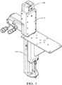
Fig. 5 is a perspective view of a gripping mechanism, a tensioning mechanism, and a rotating mechanism according to an embodiment of the invention; -
Fig. 6 is an end view of gripping mechanism according to the prior art; -
Fig. 7 is an end view of a gripping mechanism in a condition to receive a pair of wires according to an embodiment of the invention; -
Fig. 8 is an end view of the gripping mechanism ofFig. 7 in a condition to grip a pair of wires according to an embodiment of the invention; -
Fig. 9 is a cut-away view of the gripping mechanism ofFig. 7 according to an embodiment of the invention; and -
Fig. 10 is flow chart of a method of center twisting a pair of wires embodiment of the invention. - Reference will now be made in detail to embodiments, examples of which are illustrated in the accompanying drawings. In the following detailed description, numerous specific details are set forth in order to provide a thorough understanding of the various described embodiments. However, it will be apparent to one of ordinary skill in the art that the various described embodiments may be practiced without these specific details. In other instances, well-known methods, procedures, components, circuits, and networks have not been described in detail so as not to unnecessarily obscure aspects of the embodiments.
-
Figs. 1B to 5 and7 to 9 illustrate a non-limiting example of anapparatus 100 configured to center twist afirst wire 12 about asecond wire 14 according to one or more embodiments of the invention. As used herein, the first andsecond wires apparatus 100 includes asecuring mechanism 102 that is configured to secure ends of thefirst wire 12 and thesecond wire 14. The ends of the wires may be terminated by electrical terminals (not shown) while they are secured by thesecuring mechanism 102 and may further be disposed within terminal cavities of aconnector body 16 that is secured by thesecuring mechanism 102. Thesecuring mechanism 102 may include a pair of clampingjaws 104 that open to allow placement of the wire ends within thesecuring mechanism 102 and then close to secure the wire ends. The clampingjaws 104 may be manually or automatically operated. Thesecuring mechanism 102 holds the wire ends such that first andsecond wires - The
apparatus 100 also includes agripping mechanism 106 is configured to gripcentral portions 18 of the first andsecond wires second wires Fig. 6 , a prior art gripping mechanism 106PA included a pin 108PA that was placed between the first andsecond wires second wires second wires gripping mechanism 106 of theapparatus 100 eliminates the gap between the first andsecond wires - The
gripping mechanism 106 is configured to grip thecentral portions 18 of the first andsecond wires second wires central portions 18 are in contact with one another, preferably in uninterrupted or continuous contact with one another. As used herein, the first andsecond wires - As shown in
Fig. 7 , thegripping mechanism 106 defines aU-shaped groove 108 that is configured to receive and grip thecentral portions 18 of the first andsecond wires width 110 of theU-shaped groove 108 is greater than a diameter of the first andsecond wires second wires U-shaped groove 108 and thewidth 110 of theU-shaped groove 108 is less than or equal to the diameter of the first andsecond wires second wires U-shaped groove 108. Adepth 112 of theU-shaped groove 108 is greater than or equal to the diameter of thefirst wire 12 plus the diameter of thesecond wire 14. - In the illustrated example, the
U-shaped groove 108 is defined by an inflatableU-shaped bladder 114 configured to receive and grip thecentral portions 18 of the first andsecond wires Fig. 7 , theU-shaped bladder 114 is uninflated to allow the wires to be placed within theU-shaped groove 108. As shown inFig. 8 , theU-shaped bladder 114 is inflated to grip the first andsecond wires U-shaped bladder 114 is deflated to release the twistedwire pair U-shaped bladder 114 may be a pneumatic bladder or a hydraulic bladder. Inflation and deflation of theU-shaped bladder 114 may be performed by manually or automatically controlled pumps and valves. - In alternative embodiments of the apparatus, the gripping mechanism may include jaws or clamps to grip the wires. The jaws or clamps are brought into direct contact or near contact with one another to grip the wires. These jaws or clamps preferably include a complaint material on the gripping edges to inhibit damage to the wires caused by gripping and during rotation of the gripping mechanism. When the arms are in contact with one another, the respective U-shaped grooves form a channel substantially surrounding the first and second wires of the twisted pair.
- Inventors have found that the
U-shaped bladder 114 provides a reduced risk of damage to the wires than the alternative gripping mechanisms. - The
apparatus 100 also includes arotating mechanism 116 configured to rotate thegripping mechanism 106, thereby twisting the first andsecond wires second wires central portions 18 and the first andsecond wires central portions 18 as shown inFig. 1B , herein referred to as center twisting. Center twisting provides the benefit of allowing pairs of wires to be twisted after the wires are terminated and inserted within connector bodies which allows a greater level of automation to be employed in assembling a wire harness which includes twisted pairs of wires. As shown inFig. 9 , thegripping mechanism 106 has a toothed outer edge and therotating mechanism 116 has a pair or gears engaged with the toothed edge that causes thegripping mechanism 106 to rotate. One gear will continue to drive thegripping mechanism 106 when the other gear is in theU-shaped groove 108. - The
illustrated apparatus 100 also includes atensioning mechanism 118 that is configured to apply alateral offsetting force 120 to thegripping mechanism 106, thereby laterally deflecting thecentral portions 18 of the first andsecond wires second wires wire pair longitudinal tension force 122 in thetwisted wire pair tensioning mechanism 118 has laterally offset the first andsecond wires longitudinal tension force 122 has alateral tension force 124 component that is exerted against thelateral offsetting force 120 of thetensioning mechanism 118. Preferably, thelateral offsetting force 120 is greater than or equal tolateral tension force 124. - The
tensioning mechanism 118 may include an extension spring or pneumatic spring to passively generate the offsetting force. Alternatively, thetensioning mechanism 118 may include a pneumatic actuator, a hydraulic actuator, or an electrical servo motor to actively generate the offsetting force. Theapparatus 100 may include a controller (not shown) connected to tension measuring device (not shown) in thesecuring mechanism 102, such as a strain gauge to measure thelongitudinal tension force 122, calculate thelateral tension force 124 and command thetensioning mechanism 118 to apply the appropriatelateral offsetting force 120. - The
tensioning mechanism 118 provides the benefit of individually applying the offsetting force to one pair of wires at a time, thereby allowing multiple twisted pairs in a wiring harness because the force offsetting thelongitudinal tension force 122 is applied laterally. It may be possible to apply a longitudinal offsetting force when center twisting a wire pair secured within a connector body, however applying a longitudinal offsetting force is undesirable for multiple twisted pairs in a single wiring harness, since the distance between the connector bodies is decreased after the first wire pair is twisted and it would be very difficult to apply a longitudinal offsetting force to a second wire pair. - Alternative embodiments of the
apparatus 100 may be envisioned that do not included thetensioning mechanism 118 while other embodiments may be envisioned which uses other gripping means, such as the pin 108PA of the prior art shown inFig. 6 . -
Fig. 10 illustrates amethod 200 of twisting a pair of wires. Themethod 200 includes the following steps: -
STEP 202, ARRANGE A FIRST WIRE PARALLEL TO A SECOND WIRE ALONG A LONGITUDINAL AXIS, includes arranging afirst wire 12 parallel to asecond wire 14 along a longitudinal axis X; -
STEP 204, SECURE ENDS OF THE FIRST AND SECOND WIRES, includes securing ends of the first andsecond wires STEP 204 may be performed by thesecuring mechanism 102 described above; -
STEP 206, GRIP CENTRAL PORTIONS OF THE FIRST AND SECOND WIRES, includes grippingcentral portions 18 of the first andsecond wires STEP 206 may be performed by thegripping mechanism 106 described above; -
STEP 208, APPLYING A LATERAL TENSIONING FORCE TO THE FIRST AND SECOND WIRES BY DEFLECTING THE CENTRAL PORTIONS OF THE FIRST AND SECOND WIRES ORTHOGONALLY FROM THE LONGITUDINAL AXIS, applying a lateral offsetting force to the first andsecond wires central portions 18 of the first andsecond wires STEP 208 may be performed by thetensioning mechanism 118 described above; -
STEP 210, ROTATE THE CENTRAL PORTIONS OF THE CENTRAL PORTIONS OF THE FIRST AND SECOND WIRES, THEREBY TWISTING THE FIRST AND SECOND WIRES ABOUT ONE ANOTHER, includes rotating thecentral portions 18 of the first andsecond wires second wires STEP 208. Alongitudinal tension force 122 caused by the twisting of the first andsecond wires lateral offsetting force 120 duringSTEP 208. Thelongitudinal tension force 122 is preferably equal to thelateral offsetting force 120 after the completion ofSTEP 210. The deflectedcentral portions 18 of the first andsecond wires longitudinal tension force 122 duringSTEP 210.STEP 210 may be performed by thegripping mechanism 106 and therotating mechanism 116 described above. A tape may be applied to the central portions to hold the first andsecond wires STEP 210. - While this invention has been described in terms of the preferred embodiments thereof, it is not intended to be so limited, but rather only to the extent set forth in the claims that follow. For example, the above-described embodiments (and/or aspects thereof) may be used in combination with each other. In addition, many modifications may be made to configure a particular situation or material to the teachings of the invention without departing from its scope. Dimensions, types of materials, orientations of the various components, and the number and positions of the various components described herein are intended to define parameters of certain embodiments, and are by no means limiting and are merely prototypical embodiments.
- Many other embodiments and modifications within the spirit and scope of the claims will be apparent to those of skill in the art upon reviewing the above description. The scope of the invention should, therefore, be determined with reference to the following claims, along with the full scope of equivalents to which such claims are entitled.
- As used herein, 'one or more' includes a function being performed by one element, a function being performed by more than one element, e.g., in a distributed fashion, several functions being performed by one element, several functions being performed by several elements, or any combination of the above.
- It will also be understood that, although the terms first, second, etc. are, in some instances, used herein to describe various elements, these elements should not be limited by these terms. These terms are only used to distinguish one element from another. For example, a first contact could be termed a second contact, and, similarly, a second contact could be termed a first contact, without departing from the scope of the various described embodiments. The first contact and the second contact are both contacts, but they are not the same contact.
- Although the present disclosure is not so limited, the following numbered examples demonstrate one or more aspects of the disclosure.
- Example 1. A method of twisting a pair of wires, comprising the steps of: a) arranging a first wire parallel to a second wire along a longitudinal axis; b) securing ends of the first and second wires to maintain the parallel arrangement; c) gripping central portions of the first and second wires; d) rotating the central portions of the first and second wires, thereby twisting the first and second wires about one another; and e) applying a lateral offsetting force to the first and second wires by deflecting the central portions of the first and second wires orthogonally from the longitudinal axis, wherein step e) is performed prior to step d).
- Example 2. The method according to example 1, wherein a longitudinal tension force caused by the twisting of the first and second wires is less than or equal to the lateral offsetting force during step d).
- Example 3. The method according to example 2, wherein the longitudinal tension force is equal to the lateral offsetting force after the completion of step d).
- Example 4. The method according to example 3, wherein the deflected central portions of the first and second wires are drawn toward the longitudinal axis by an increase in the longitudinal tension force during step d).
- Example 5. The method according to example 1, wherein the ends of the first and second wires are attached to electrical terminals.
- Example 6. The method according to example 5, wherein the electrical terminals are contained within electrical connector housings.
- Example 7. The method according to example 1, wherein step d) right-hand helically twists the first and second wires are about one another on one side of the central portions of the first and second wires and left-hand helically twists the first and second wires about one another on an opposite side of the central portions of the first and second wires.
- Example 8. The method according to example 1, wherein inner surfaces of the central portions of the first and second wires are in contact with one another during steps c) and d).
- Example 9. The method according to example 8, wherein the inner surfaces of the central portions of the first and second wires are in uninterrupted contact with one another during steps c) and d).
- Example 10. The method according to example 8, wherein the inner surfaces of the central portions of the first and second wires are in continuous contact with one another during steps c) and d).
- Example 11. An apparatus configured to twist a first wire about a second wire, comprising: a securing mechanism configured to secure ends of the first wire and the second wire, wherein the first wire is arranged parallel to the second wire along a longitudinal axis; a gripping mechanism configured to grip central portions of the first and second wires; a tensioning mechanism configured to apply a lateral offsetting force to the gripping mechanism, thereby deflecting the central portions of the first and second wires orthogonally from the longitudinal axis; and a rotating mechanism configured to rotate the gripping mechanism, thereby twisting the first and second wires about one another.
- Example 12. The apparatus according to example 11, wherein the tensioning mechanism includes an extension spring.
- Example 13. The apparatus according to example 11, wherein the tensioning mechanism includes a pneumatic spring.
- Example 14. The apparatus according to example 11, wherein the tensioning mechanism includes a pneumatic actuator.
- Example 15. The apparatus according to example 11, wherein the tensioning mechanism includes a hydraulic actuator.
- Example 16. The apparatus according to example 11, wherein the tensioning mechanism includes an electrical servo motor.
- Example 17. The apparatus according to example 11, wherein the apparatus is configured to twist the first wire about the second wire such that the first and second wires are right-hand helically twisted about one another on one side of the central portions and the first and second wires are left-hand helically twisted about one another on an opposite side of the central portions.
- Example 18. The apparatus according to example 11, wherein the securing mechanism is configured to secure an electrical connector housing in which the ends of the first and second wires are disposed.
- Example 19. The apparatus according to example 11, wherein the gripping mechanism is configured to grip the central portions of the first and second wires such that inner surfaces of the central portions of the first and second wires are in contact with one another.
- Example 20. The apparatus according to example 19, wherein the gripping mechanism is configured to grip the central portions of the first and second wires such that the inner surfaces of the central portions of the first and second wires are in uninterrupted contact with one another.
- Example 21. The apparatus according to example 19, wherein the gripping mechanism is configured to grip the central portions of the first and second wires such that the inner surfaces of the central portions of the first and second wires are in continuous contact with one another.
- Example 22. The apparatus according to example 19, wherein the gripping mechanism defines a U-shaped groove configured to receive and grip the central portions of the first and second wires.
- Example 23. The apparatus according to example 22, wherein a width of the U-shaped groove is greater than a diameter of the first and second wires when the first and second wires are received within the U-shaped groove and wherein the width of the U-shaped groove is less than or equal to the diameter of the first and second wires when the first and second wires are gripped within the U-shaped groove.
- Example 24. The apparatus according to example 23, wherein the U-shaped groove is defined by an inflatable U-shaped bladder configured to receive and grip the central portions of the first and second wires.
- Example 25. The apparatus according to example 19, wherein the gripping mechanism does not comprise a pin that is configured to be inserted between the central portions of the first and second wires.
- The terminology used in the description of the various described embodiments herein is for the purpose of describing particular embodiments only and is not intended to be limiting. As used in the description of the various described embodiments and the appended claims, the singular forms "a", "an" and "the" are intended to include the plural forms as well, unless the context clearly indicates otherwise. It will also be understood that the term "and/or" as used herein refers to and encompasses any and all possible combinations of one or more of the associated listed items. It will be further understood that the terms "includes," "including," "comprises," and/or "comprising," when used in this specification, specify the presence of stated features, integers, steps, operations, elements, and/or components, but do not preclude the presence or addition of one or more other features, integers, steps, operations, elements, components, and/or groups thereof.
- As used herein, the term "if' is, optionally, construed to mean "when" or "upon" or "in response to determining" or "in response to detecting," depending on the context. Similarly, the phrase "if it is determined" or "if [a stated condition or event] is detected" is, optionally, construed to mean "upon determining" or "in response to determining" or "upon detecting [the stated condition or event]" or "in response to detecting [the stated condition or event]," depending on the context.
- Additionally, while terms of ordinance or orientation may be used herein these elements should not be limited by these terms. All terms of ordinance or orientation, unless stated otherwise, are used for purposes distinguishing one element from another, and do not denote any particular order, order of operations, direction or orientation unless stated otherwise.
Claims (15)
- A method of twisting a pair of wires, comprising the steps of:a) arranging a first wire (12) parallel to a second wire (14) along a longitudinal axis (step 202);b) securing ends of the first and second wires (12, 14) to maintain the parallel arrangement (step 204);c) gripping central portions (18) of the first and second wires (12, 14) (step 206);d) rotating the central portions (18) of the first and second wires, thereby twisting the first and second wires about one another (step 210); ande) applying a lateral offsetting force (120) to the first and second wires (12, 14) by deflecting the central portions (18) of the first and second wires (12, 14) orthogonally from the longitudinal axis (step 208), wherein step e) (208) is performed prior to step d) (step 210).
- The method according to claim 1, wherein a longitudinal tension force (122) caused by the twisting of the first and second wires (12, 14) is less than or equal to the lateral offsetting force (120) during step d) (step 210, wherein the longitudinal tension force (122) is equal to the lateral offsetting force (120) after the completion of step d) (step 210).
- The method according to claim 2, wherein the deflected central portions (18) of the first and second wires (12, 14) are drawn toward the longitudinal axis by an increase in the longitudinal tension force (122) during step d).
- The method according to any preceding claim, wherein the ends of the first and second wires (12, 14) are attached to electrical terminals and wherein the electrical terminals are contained within electrical connector housings.
- The method according to any one of the preceding claims, wherein step d) right-hand helically twists the first and second wires (12, 14) are about one another on one side of the central portions (18) of the first and second wires (12, 14) and left-hand helically twists the first and second wires (12, 14) about one another on an opposite side of the central portions (18) of the first and second wires (12, 14).
- The method according to any one of the preceding claims , wherein inner surfaces of the central portions (18) of the first and second wires (12, 14) are in contact with one another during steps c) (step 206) and d) (step 210).
- An apparatus (100) configured to twist a first wire about a second wire, comprising:a securing mechanism (102) configured to secure ends of the first wire (12) and the second wire (14), wherein the first wire (12) is arranged parallel to the second wire (14) along a longitudinal axis;a gripping mechanism (106) configured to grip central portions (18) of the first and second wires (12, 14);a tensioning mechanism (118) configured to apply a lateral offsetting force (120) to the gripping mechanism (106), thereby deflecting the central portions (18) of the first and second wires (12, 14) orthogonally from the longitudinal axis; anda rotating mechanism (116) configured to rotate the gripping mechanism (106), thereby twisting the first and second wires (12, 14) about one another.
- The apparatus (100) according to claim 7, wherein the tensioning mechanism (118) includes at least one of an extension spring, pneumatic spring, a pneumatic actuator, a hydraulic actuator, or an electrical servo motor.
- The apparatus (100) according to claim 7 or 8, wherein the apparatus (100) is configured to twist the first wire (12) about the second wire (14) such that the first and second wires (12, 14) are right-hand helically twisted about one another on one side of the central portions (18) and the first and second wires (12, 14) are left-hand helically twisted about one another on an opposite side of the central portions (18).
- The apparatus (100) according to any one of claims 7 to 9, wherein the securing mechanism (102) is configured to secure an electrical connector housing in which the ends of the first and second wires (12, 14) are disposed.
- The apparatus (100) according to any one of claims 7 to 10, wherein the gripping mechanism (106) is configured to grip the central portions (18) of the first and second wires (12, 14) such that inner surfaces of the central portions (18) of the first and second wires (12, 14) are in contact with one another.
- The apparatus (100) according to any one of claims 7 to 11, wherein the gripping mechanism (106) is configured to grip the central portions (18) of the first and second wires (12, 14) such that the inner surfaces of the central portions (18) of the first and second wires (12, 14) are in uninterrupted contact with one another.
- The apparatus (100) according to any one of claims 7 to 12, wherein the gripping mechanism (106) defines a U-shaped groove (108) configured to receive and grip the central portions (18) of the first and second wires (12, 14).
- The apparatus (100) according to claim 13, wherein a width of the U-shaped groove (108) is greater than a diameter of the first and second wires (12, 14) when the first and second wires (12, 14) are received within the U-shaped groove (108) and wherein the width of the U-shaped groove (108) is less than or equal to the diameter of the first and second wires (12, 14) when the first and second wires (12, 14) are gripped within the U-shaped groove (108).
- The apparatus according to claim 13 or 14, wherein the U-shaped groove (108) is defined by an inflatable U-shaped bladder (114) configured to receive and grip the central portions (18) of the first and second wires (12, 14).
Priority Applications (1)
| Application Number | Priority Date | Filing Date | Title |
|---|---|---|---|
| EP22151268.4A EP4011520B1 (en) | 2019-07-18 | 2020-07-17 | Apparatus and method for center twisting wires |
Applications Claiming Priority (1)
| Application Number | Priority Date | Filing Date | Title |
|---|---|---|---|
| US16/515,720 US10946434B2 (en) | 2019-07-18 | 2019-07-18 | Apparatus and method for center twisting wires |
Related Child Applications (1)
| Application Number | Title | Priority Date | Filing Date |
|---|---|---|---|
| EP22151268.4A Division EP4011520B1 (en) | 2019-07-18 | 2020-07-17 | Apparatus and method for center twisting wires |
Publications (2)
| Publication Number | Publication Date |
|---|---|
| EP3778063A1 true EP3778063A1 (en) | 2021-02-17 |
| EP3778063B1 EP3778063B1 (en) | 2022-01-19 |
Family
ID=71670135
Family Applications (2)
| Application Number | Title | Priority Date | Filing Date |
|---|---|---|---|
| EP22151268.4A Active EP4011520B1 (en) | 2019-07-18 | 2020-07-17 | Apparatus and method for center twisting wires |
| EP20186497.2A Active EP3778063B1 (en) | 2019-07-18 | 2020-07-17 | Apparatus and method for center twisting wires |
Family Applications Before (1)
| Application Number | Title | Priority Date | Filing Date |
|---|---|---|---|
| EP22151268.4A Active EP4011520B1 (en) | 2019-07-18 | 2020-07-17 | Apparatus and method for center twisting wires |
Country Status (3)
| Country | Link |
|---|---|
| US (2) | US10946434B2 (en) |
| EP (2) | EP4011520B1 (en) |
| CN (1) | CN112242216B (en) |
Families Citing this family (2)
| Publication number | Priority date | Publication date | Assignee | Title |
|---|---|---|---|---|
| EP4219041B1 (en) | 2022-01-28 | 2025-11-12 | Aptiv Technologies AG | Apparatus and method for twisting wires |
| CN118950893B (en) * | 2024-09-27 | 2025-03-11 | 湖南汇米精密机械有限公司 | A wire automatic forming machine |
Citations (5)
| Publication number | Priority date | Publication date | Assignee | Title |
|---|---|---|---|---|
| US3052079A (en) * | 1958-11-10 | 1962-09-04 | Western Electric Co | Apparatus for twisting strands |
| DE7606095U1 (en) * | 1976-02-28 | 1976-06-24 | Knorr-Bremse Gmbh, 8000 Muenchen | DEVICE FOR TWISTING WIRE AND LIKE LONG-BODY, ESPECIALLY FOR TWISTING WIRES USED FOR TENSIONING OF CHARGES |
| DE2812208A1 (en) * | 1978-03-20 | 1979-10-04 | Kabel Metallwerke Ghh | Large diameter cable mfr. - with the strands twisted into bundles before cable twisting to preserve protective claddings |
| EP0895254A1 (en) * | 1997-07-17 | 1999-02-03 | 3 V Torsad | Twisting machine with programmable control |
| JP2001307569A (en) * | 2000-04-18 | 2001-11-02 | Sumitomo Wiring Syst Ltd | Connector holder for twisting work |
Family Cites Families (26)
| Publication number | Priority date | Publication date | Assignee | Title |
|---|---|---|---|---|
| US1581794A (en) * | 1921-06-15 | 1926-04-20 | Ti It Machine Company | Process of and apparatus for forming wire ties |
| US1543520A (en) * | 1924-02-07 | 1925-06-23 | Mark M Finlayson | Wire-twisting tool |
| US1572907A (en) * | 1925-05-13 | 1926-02-16 | Frank P Pike | Twisting device |
| US2498920A (en) * | 1947-06-24 | 1950-02-28 | George H Holland | Implement for tying knots |
| US2604883A (en) * | 1949-02-17 | 1952-07-29 | D Avaucourt Pierre De Vitry | Wire saw strand and method of making the same |
| US2654403A (en) * | 1950-05-15 | 1953-10-06 | Roe Ernest | Flat wire tying machine |
| US2796662A (en) * | 1954-08-13 | 1957-06-25 | John A Saum | Wire splicer clamp |
| US2831356A (en) * | 1956-02-20 | 1958-04-22 | Kopparfors Ab | Movement transmitting mechanism with automatic stopping means |
| DE2707197A1 (en) | 1977-02-17 | 1978-08-24 | Aeg Telefunken Kabelwerke | METHOD OF MANUFACTURING A STRINGING ELEMENT FOR COMMUNICATION CABLE |
| DE3721199C1 (en) * | 1987-06-26 | 1988-12-08 | Ni Skij Pk I T Kabel Nyj I Nik | Method and apparatus for the varyingly directed stranding of wires |
| US5494081A (en) * | 1994-01-26 | 1996-02-27 | L&P Property Management Company | Wire twister pinion and assembly |
| US5605181A (en) * | 1995-02-13 | 1997-02-25 | Northrop Grumman Corporation | Portable wire twisting tool |
| JPH08340627A (en) * | 1995-06-09 | 1996-12-24 | Hitachi Cable Ltd | Structure for preventing move of cable terminal sheath |
| DE19631770C2 (en) * | 1996-08-06 | 1998-08-27 | Gluth Systemtechnik Gmbh | Method for twisting at least two individual lines |
| JP2000149684A (en) * | 1998-11-16 | 2000-05-30 | Sumitomo Wiring Syst Ltd | Working device for twisted electric wire |
| JP4884024B2 (en) * | 2006-02-15 | 2012-02-22 | 矢崎総業株式会社 | Twisted wire manufacturing method and manufacturing apparatus |
| US9597724B2 (en) * | 2010-09-02 | 2017-03-21 | Jon R. Kodi | Wire twisting tools and methods |
| JP5848093B2 (en) * | 2011-11-01 | 2016-01-27 | 株式会社ブリヂストン | Metal wire connecting method and connecting device |
| US9117573B2 (en) | 2013-05-30 | 2015-08-25 | Delphi Technologies, Inc. | Integrated wire cable twisting, wrapping, and testing apparatus and method of operating same |
| BR112015027583A2 (en) | 2014-01-28 | 2017-09-19 | Delphi Tech Inc | METHOD FOR CONSTRUCTING A TAPE-WRAPPED TWISTED PAIR CABLE, AND TAPE-WRAPPED UNSHIELDED TWISTED PAIR CABLE |
| WO2017159604A1 (en) * | 2016-03-14 | 2017-09-21 | 新明和工業株式会社 | Electric wire twisting device and electric wire twisting method |
| RS62300B1 (en) | 2016-10-03 | 2021-09-30 | Komax Holding Ag | Method and device for rotational alignment of preconfigured cable ends of a wire harness |
| JP6475765B2 (en) * | 2017-01-17 | 2019-02-27 | 矢崎総業株式会社 | Twist wire manufacturing apparatus and twist wire manufacturing method |
| US9899128B1 (en) | 2017-01-24 | 2018-02-20 | Delphi Technologies, Inc. | Signal transmission cable assembly with ungrounded sheath containing electrically conductive particles |
| EP3557592B1 (en) * | 2018-04-17 | 2021-01-20 | Komax Holding Ag | Device and method for twisting a first and second electrical single wire line to form a cable pair |
| CN109979692B (en) * | 2019-03-25 | 2020-06-26 | 绍兴市梓昂新材料有限公司 | A maintenance-friendly talcum powder laying device before cable winding |
-
2019
- 2019-07-18 US US16/515,720 patent/US10946434B2/en active Active
-
2020
- 2020-07-17 EP EP22151268.4A patent/EP4011520B1/en active Active
- 2020-07-17 EP EP20186497.2A patent/EP3778063B1/en active Active
- 2020-07-20 CN CN202010697350.3A patent/CN112242216B/en active Active
-
2021
- 2021-02-05 US US17/168,492 patent/US11517957B2/en active Active
Patent Citations (5)
| Publication number | Priority date | Publication date | Assignee | Title |
|---|---|---|---|---|
| US3052079A (en) * | 1958-11-10 | 1962-09-04 | Western Electric Co | Apparatus for twisting strands |
| DE7606095U1 (en) * | 1976-02-28 | 1976-06-24 | Knorr-Bremse Gmbh, 8000 Muenchen | DEVICE FOR TWISTING WIRE AND LIKE LONG-BODY, ESPECIALLY FOR TWISTING WIRES USED FOR TENSIONING OF CHARGES |
| DE2812208A1 (en) * | 1978-03-20 | 1979-10-04 | Kabel Metallwerke Ghh | Large diameter cable mfr. - with the strands twisted into bundles before cable twisting to preserve protective claddings |
| EP0895254A1 (en) * | 1997-07-17 | 1999-02-03 | 3 V Torsad | Twisting machine with programmable control |
| JP2001307569A (en) * | 2000-04-18 | 2001-11-02 | Sumitomo Wiring Syst Ltd | Connector holder for twisting work |
Also Published As
| Publication number | Publication date |
|---|---|
| US11517957B2 (en) | 2022-12-06 |
| EP4011520B1 (en) | 2023-04-26 |
| EP4011520A1 (en) | 2022-06-15 |
| US20210016341A1 (en) | 2021-01-21 |
| CN112242216A (en) | 2021-01-19 |
| CN112242216B (en) | 2022-06-10 |
| US20210154726A1 (en) | 2021-05-27 |
| US10946434B2 (en) | 2021-03-16 |
| EP3778063B1 (en) | 2022-01-19 |
Similar Documents
| Publication | Publication Date | Title |
|---|---|---|
| EP3767644B1 (en) | Apparatus and method for center twisting wires | |
| US9240662B2 (en) | Terminal treatment method and terminal treatment apparatus for coaxial cable | |
| US11517957B2 (en) | Apparatus and method for center twisting wires | |
| JP2018060791A (en) | Device and method for attaching plug housing with preassembled cable end of cable harness | |
| US20160203889A1 (en) | Terminal treatment method for a coaxial cable | |
| CN110391053B (en) | Apparatus and method for stranding first and second single wires to form a duplex cable | |
| WO2015178165A1 (en) | Method for manufacturing wound electronic component | |
| CN100423365C (en) | Wire terminal connection structure and wire terminal connection method | |
| CN117220116A (en) | Method and device for untwisting and smoothing a cable end of a stranded cable | |
| CN116581617B (en) | Wire connecting sleeve | |
| CN113285321B (en) | Wire correction method and wire correction device | |
| US20240079863A1 (en) | Drain wire correcting device and drain wire correcting method | |
| CN215008808U (en) | Wear-resistant adjustable automobile wire harness with flexible protective sleeve | |
| JP4653037B2 (en) | Twisted pair electric wire for in-vehicle use, method for forming twisted pair electric wire, and forming apparatus | |
| JP5597464B2 (en) | Method for forming twisted wire and twisted structure | |
| US20250309623A1 (en) | Twisted Pair Cable Processing System and Twisted Pair Cable Cutting Method | |
| JP2002100250A (en) | Manufacturing method of twisted electric wire | |
| JP7310493B2 (en) | Hollow covered stranded wire manufacturing device and hollow covered stranded wire manufacturing method | |
| ES2776206T3 (en) | Procedure for establishing an electrical connection between an end cap and a continuous transposed conductor, and arrangement | |
| US20120227858A1 (en) | Apparatus for Separating the Connecting Ends of Twisted Wires | |
| JP4042433B2 (en) | WIRING END INSULATION DEVICE AND WIRING END INSULATION METHOD | |
| JP2000009595A (en) | Tensile test method for wire | |
| JP2010251233A (en) | Electric wire terminal processing equipment |
Legal Events
| Date | Code | Title | Description |
|---|---|---|---|
| PUAI | Public reference made under article 153(3) epc to a published international application that has entered the european phase |
Free format text: ORIGINAL CODE: 0009012 |
|
| STAA | Information on the status of an ep patent application or granted ep patent |
Free format text: STATUS: THE APPLICATION HAS BEEN PUBLISHED |
|
| STAA | Information on the status of an ep patent application or granted ep patent |
Free format text: STATUS: REQUEST FOR EXAMINATION WAS MADE |
|
| AK | Designated contracting states |
Kind code of ref document: A1 Designated state(s): AL AT BE BG CH CY CZ DE DK EE ES FI FR GB GR HR HU IE IS IT LI LT LU LV MC MK MT NL NO PL PT RO RS SE SI SK SM TR |
|
| AX | Request for extension of the european patent |
Extension state: BA ME |
|
| 17P | Request for examination filed |
Effective date: 20210208 |
|
| RBV | Designated contracting states (corrected) |
Designated state(s): AL AT BE BG CH CY CZ DE DK EE ES FI FR GB GR HR HU IE IS IT LI LT LU LV MC MK MT NL NO PL PT RO RS SE SI SK SM TR |
|
| GRAP | Despatch of communication of intention to grant a patent |
Free format text: ORIGINAL CODE: EPIDOSNIGR1 |
|
| STAA | Information on the status of an ep patent application or granted ep patent |
Free format text: STATUS: GRANT OF PATENT IS INTENDED |
|
| INTG | Intention to grant announced |
Effective date: 20210826 |
|
| GRAJ | Information related to disapproval of communication of intention to grant by the applicant or resumption of examination proceedings by the epo deleted |
Free format text: ORIGINAL CODE: EPIDOSDIGR1 |
|
| STAA | Information on the status of an ep patent application or granted ep patent |
Free format text: STATUS: REQUEST FOR EXAMINATION WAS MADE |
|
| GRAS | Grant fee paid |
Free format text: ORIGINAL CODE: EPIDOSNIGR3 |
|
| STAA | Information on the status of an ep patent application or granted ep patent |
Free format text: STATUS: GRANT OF PATENT IS INTENDED |
|
| GRAP | Despatch of communication of intention to grant a patent |
Free format text: ORIGINAL CODE: EPIDOSNIGR1 |
|
| GRAA | (expected) grant |
Free format text: ORIGINAL CODE: 0009210 |
|
| STAA | Information on the status of an ep patent application or granted ep patent |
Free format text: STATUS: THE PATENT HAS BEEN GRANTED |
|
| INTC | Intention to grant announced (deleted) | ||
| INTG | Intention to grant announced |
Effective date: 20211215 |
|
| AK | Designated contracting states |
Kind code of ref document: B1 Designated state(s): AL AT BE BG CH CY CZ DE DK EE ES FI FR GB GR HR HU IE IS IT LI LT LU LV MC MK MT NL NO PL PT RO RS SE SI SK SM TR |
|
| REG | Reference to a national code |
Ref country code: GB Ref legal event code: FG4D |
|
| REG | Reference to a national code |
Ref country code: CH Ref legal event code: EP |
|
| REG | Reference to a national code |
Ref country code: DE Ref legal event code: R096 Ref document number: 602020001663 Country of ref document: DE |
|
| REG | Reference to a national code |
Ref country code: AT Ref legal event code: REF Ref document number: 1463488 Country of ref document: AT Kind code of ref document: T Effective date: 20220215 |
|
| REG | Reference to a national code |
Ref country code: IE Ref legal event code: FG4D |
|
| REG | Reference to a national code |
Ref country code: LT Ref legal event code: MG9D |
|
| REG | Reference to a national code |
Ref country code: NL Ref legal event code: MP Effective date: 20220119 |
|
| REG | Reference to a national code |
Ref country code: AT Ref legal event code: MK05 Ref document number: 1463488 Country of ref document: AT Kind code of ref document: T Effective date: 20220119 |
|
| PG25 | Lapsed in a contracting state [announced via postgrant information from national office to epo] |
Ref country code: NL Free format text: LAPSE BECAUSE OF FAILURE TO SUBMIT A TRANSLATION OF THE DESCRIPTION OR TO PAY THE FEE WITHIN THE PRESCRIBED TIME-LIMIT Effective date: 20220119 |
|
| PG25 | Lapsed in a contracting state [announced via postgrant information from national office to epo] |
Ref country code: SE Free format text: LAPSE BECAUSE OF FAILURE TO SUBMIT A TRANSLATION OF THE DESCRIPTION OR TO PAY THE FEE WITHIN THE PRESCRIBED TIME-LIMIT Effective date: 20220119 Ref country code: RS Free format text: LAPSE BECAUSE OF FAILURE TO SUBMIT A TRANSLATION OF THE DESCRIPTION OR TO PAY THE FEE WITHIN THE PRESCRIBED TIME-LIMIT Effective date: 20220119 Ref country code: PT Free format text: LAPSE BECAUSE OF FAILURE TO SUBMIT A TRANSLATION OF THE DESCRIPTION OR TO PAY THE FEE WITHIN THE PRESCRIBED TIME-LIMIT Effective date: 20220519 Ref country code: NO Free format text: LAPSE BECAUSE OF FAILURE TO SUBMIT A TRANSLATION OF THE DESCRIPTION OR TO PAY THE FEE WITHIN THE PRESCRIBED TIME-LIMIT Effective date: 20220419 Ref country code: LT Free format text: LAPSE BECAUSE OF FAILURE TO SUBMIT A TRANSLATION OF THE DESCRIPTION OR TO PAY THE FEE WITHIN THE PRESCRIBED TIME-LIMIT Effective date: 20220119 Ref country code: HR Free format text: LAPSE BECAUSE OF FAILURE TO SUBMIT A TRANSLATION OF THE DESCRIPTION OR TO PAY THE FEE WITHIN THE PRESCRIBED TIME-LIMIT Effective date: 20220119 Ref country code: ES Free format text: LAPSE BECAUSE OF FAILURE TO SUBMIT A TRANSLATION OF THE DESCRIPTION OR TO PAY THE FEE WITHIN THE PRESCRIBED TIME-LIMIT Effective date: 20220119 Ref country code: BG Free format text: LAPSE BECAUSE OF FAILURE TO SUBMIT A TRANSLATION OF THE DESCRIPTION OR TO PAY THE FEE WITHIN THE PRESCRIBED TIME-LIMIT Effective date: 20220419 |
|
| PG25 | Lapsed in a contracting state [announced via postgrant information from national office to epo] |
Ref country code: PL Free format text: LAPSE BECAUSE OF FAILURE TO SUBMIT A TRANSLATION OF THE DESCRIPTION OR TO PAY THE FEE WITHIN THE PRESCRIBED TIME-LIMIT Effective date: 20220119 Ref country code: LV Free format text: LAPSE BECAUSE OF FAILURE TO SUBMIT A TRANSLATION OF THE DESCRIPTION OR TO PAY THE FEE WITHIN THE PRESCRIBED TIME-LIMIT Effective date: 20220119 Ref country code: GR Free format text: LAPSE BECAUSE OF FAILURE TO SUBMIT A TRANSLATION OF THE DESCRIPTION OR TO PAY THE FEE WITHIN THE PRESCRIBED TIME-LIMIT Effective date: 20220420 Ref country code: FI Free format text: LAPSE BECAUSE OF FAILURE TO SUBMIT A TRANSLATION OF THE DESCRIPTION OR TO PAY THE FEE WITHIN THE PRESCRIBED TIME-LIMIT Effective date: 20220119 Ref country code: AT Free format text: LAPSE BECAUSE OF FAILURE TO SUBMIT A TRANSLATION OF THE DESCRIPTION OR TO PAY THE FEE WITHIN THE PRESCRIBED TIME-LIMIT Effective date: 20220119 |
|
| PG25 | Lapsed in a contracting state [announced via postgrant information from national office to epo] |
Ref country code: IS Free format text: LAPSE BECAUSE OF FAILURE TO SUBMIT A TRANSLATION OF THE DESCRIPTION OR TO PAY THE FEE WITHIN THE PRESCRIBED TIME-LIMIT Effective date: 20220519 |
|
| REG | Reference to a national code |
Ref country code: DE Ref legal event code: R097 Ref document number: 602020001663 Country of ref document: DE |
|
| PG25 | Lapsed in a contracting state [announced via postgrant information from national office to epo] |
Ref country code: SM Free format text: LAPSE BECAUSE OF FAILURE TO SUBMIT A TRANSLATION OF THE DESCRIPTION OR TO PAY THE FEE WITHIN THE PRESCRIBED TIME-LIMIT Effective date: 20220119 Ref country code: SK Free format text: LAPSE BECAUSE OF FAILURE TO SUBMIT A TRANSLATION OF THE DESCRIPTION OR TO PAY THE FEE WITHIN THE PRESCRIBED TIME-LIMIT Effective date: 20220119 Ref country code: RO Free format text: LAPSE BECAUSE OF FAILURE TO SUBMIT A TRANSLATION OF THE DESCRIPTION OR TO PAY THE FEE WITHIN THE PRESCRIBED TIME-LIMIT Effective date: 20220119 Ref country code: EE Free format text: LAPSE BECAUSE OF FAILURE TO SUBMIT A TRANSLATION OF THE DESCRIPTION OR TO PAY THE FEE WITHIN THE PRESCRIBED TIME-LIMIT Effective date: 20220119 Ref country code: DK Free format text: LAPSE BECAUSE OF FAILURE TO SUBMIT A TRANSLATION OF THE DESCRIPTION OR TO PAY THE FEE WITHIN THE PRESCRIBED TIME-LIMIT Effective date: 20220119 Ref country code: CZ Free format text: LAPSE BECAUSE OF FAILURE TO SUBMIT A TRANSLATION OF THE DESCRIPTION OR TO PAY THE FEE WITHIN THE PRESCRIBED TIME-LIMIT Effective date: 20220119 |
|
| PLBE | No opposition filed within time limit |
Free format text: ORIGINAL CODE: 0009261 |
|
| STAA | Information on the status of an ep patent application or granted ep patent |
Free format text: STATUS: NO OPPOSITION FILED WITHIN TIME LIMIT |
|
| PG25 | Lapsed in a contracting state [announced via postgrant information from national office to epo] |
Ref country code: AL Free format text: LAPSE BECAUSE OF FAILURE TO SUBMIT A TRANSLATION OF THE DESCRIPTION OR TO PAY THE FEE WITHIN THE PRESCRIBED TIME-LIMIT Effective date: 20220119 |
|
| 26N | No opposition filed |
Effective date: 20221020 |
|
| PG25 | Lapsed in a contracting state [announced via postgrant information from national office to epo] |
Ref country code: SI Free format text: LAPSE BECAUSE OF FAILURE TO SUBMIT A TRANSLATION OF THE DESCRIPTION OR TO PAY THE FEE WITHIN THE PRESCRIBED TIME-LIMIT Effective date: 20220119 Ref country code: MC Free format text: LAPSE BECAUSE OF FAILURE TO SUBMIT A TRANSLATION OF THE DESCRIPTION OR TO PAY THE FEE WITHIN THE PRESCRIBED TIME-LIMIT Effective date: 20220119 |
|
| REG | Reference to a national code |
Ref country code: BE Ref legal event code: MM Effective date: 20220731 |
|
| PG25 | Lapsed in a contracting state [announced via postgrant information from national office to epo] |
Ref country code: LU Free format text: LAPSE BECAUSE OF NON-PAYMENT OF DUE FEES Effective date: 20220717 |
|
| PG25 | Lapsed in a contracting state [announced via postgrant information from national office to epo] |
Ref country code: BE Free format text: LAPSE BECAUSE OF NON-PAYMENT OF DUE FEES Effective date: 20220731 |
|
| P01 | Opt-out of the competence of the unified patent court (upc) registered |
Effective date: 20230424 |
|
| PG25 | Lapsed in a contracting state [announced via postgrant information from national office to epo] |
Ref country code: IT Free format text: LAPSE BECAUSE OF FAILURE TO SUBMIT A TRANSLATION OF THE DESCRIPTION OR TO PAY THE FEE WITHIN THE PRESCRIBED TIME-LIMIT Effective date: 20220119 Ref country code: IE Free format text: LAPSE BECAUSE OF NON-PAYMENT OF DUE FEES Effective date: 20220717 |
|
| REG | Reference to a national code |
Ref country code: CH Ref legal event code: PL |
|
| PG25 | Lapsed in a contracting state [announced via postgrant information from national office to epo] |
Ref country code: MK Free format text: LAPSE BECAUSE OF FAILURE TO SUBMIT A TRANSLATION OF THE DESCRIPTION OR TO PAY THE FEE WITHIN THE PRESCRIBED TIME-LIMIT Effective date: 20220119 Ref country code: CY Free format text: LAPSE BECAUSE OF FAILURE TO SUBMIT A TRANSLATION OF THE DESCRIPTION OR TO PAY THE FEE WITHIN THE PRESCRIBED TIME-LIMIT Effective date: 20220119 Ref country code: CH Free format text: LAPSE BECAUSE OF NON-PAYMENT OF DUE FEES Effective date: 20230731 |
|
| PG25 | Lapsed in a contracting state [announced via postgrant information from national office to epo] |
Ref country code: HU Free format text: LAPSE BECAUSE OF FAILURE TO SUBMIT A TRANSLATION OF THE DESCRIPTION OR TO PAY THE FEE WITHIN THE PRESCRIBED TIME-LIMIT; INVALID AB INITIO Effective date: 20200717 |
|
| PG25 | Lapsed in a contracting state [announced via postgrant information from national office to epo] |
Ref country code: MT Free format text: LAPSE BECAUSE OF FAILURE TO SUBMIT A TRANSLATION OF THE DESCRIPTION OR TO PAY THE FEE WITHIN THE PRESCRIBED TIME-LIMIT Effective date: 20220119 |
|
| REG | Reference to a national code |
Ref country code: DE Ref legal event code: R081 Ref document number: 602020001663 Country of ref document: DE Owner name: APTIV TECHNOLOGIES AG, CH Free format text: FORMER OWNER: APTIV TECHNOLOGIES LIMITED, ST. MICHAEL, BB |
|
| PGFP | Annual fee paid to national office [announced via postgrant information from national office to epo] |
Ref country code: DE Payment date: 20250618 Year of fee payment: 6 |
|
| PGFP | Annual fee paid to national office [announced via postgrant information from national office to epo] |
Ref country code: GB Payment date: 20250703 Year of fee payment: 6 |
|
| PGFP | Annual fee paid to national office [announced via postgrant information from national office to epo] |
Ref country code: FR Payment date: 20250703 Year of fee payment: 6 |
|
| PG25 | Lapsed in a contracting state [announced via postgrant information from national office to epo] |
Ref country code: TR Free format text: LAPSE BECAUSE OF FAILURE TO SUBMIT A TRANSLATION OF THE DESCRIPTION OR TO PAY THE FEE WITHIN THE PRESCRIBED TIME-LIMIT Effective date: 20220119 |