EP3778004A1 - Flow type reactor and manufacturing facility including same - Google Patents
Flow type reactor and manufacturing facility including same Download PDFInfo
- Publication number
- EP3778004A1 EP3778004A1 EP19775080.5A EP19775080A EP3778004A1 EP 3778004 A1 EP3778004 A1 EP 3778004A1 EP 19775080 A EP19775080 A EP 19775080A EP 3778004 A1 EP3778004 A1 EP 3778004A1
- Authority
- EP
- European Patent Office
- Prior art keywords
- tubular reaction
- reaction line
- flow reactor
- flow channel
- flow
- Prior art date
- Legal status (The legal status is an assumption and is not a legal conclusion. Google has not performed a legal analysis and makes no representation as to the accuracy of the status listed.)
- Granted
Links
Images

Classifications
-
- B—PERFORMING OPERATIONS; TRANSPORTING
- B01—PHYSICAL OR CHEMICAL PROCESSES OR APPARATUS IN GENERAL
- B01J—CHEMICAL OR PHYSICAL PROCESSES, e.g. CATALYSIS OR COLLOID CHEMISTRY; THEIR RELEVANT APPARATUS
- B01J19/00—Chemical, physical or physico-chemical processes in general; Their relevant apparatus
- B01J19/24—Stationary reactors without moving elements inside
- B01J19/2415—Tubular reactors
- B01J19/243—Tubular reactors spirally, concentrically or zigzag wound
-
- B—PERFORMING OPERATIONS; TRANSPORTING
- B01—PHYSICAL OR CHEMICAL PROCESSES OR APPARATUS IN GENERAL
- B01J—CHEMICAL OR PHYSICAL PROCESSES, e.g. CATALYSIS OR COLLOID CHEMISTRY; THEIR RELEVANT APPARATUS
- B01J19/00—Chemical, physical or physico-chemical processes in general; Their relevant apparatus
- B01J19/0006—Controlling or regulating processes
- B01J19/0013—Controlling the temperature of the process
-
- B—PERFORMING OPERATIONS; TRANSPORTING
- B01—PHYSICAL OR CHEMICAL PROCESSES OR APPARATUS IN GENERAL
- B01J—CHEMICAL OR PHYSICAL PROCESSES, e.g. CATALYSIS OR COLLOID CHEMISTRY; THEIR RELEVANT APPARATUS
- B01J19/00—Chemical, physical or physico-chemical processes in general; Their relevant apparatus
- B01J19/18—Stationary reactors having moving elements inside
-
- B—PERFORMING OPERATIONS; TRANSPORTING
- B01—PHYSICAL OR CHEMICAL PROCESSES OR APPARATUS IN GENERAL
- B01J—CHEMICAL OR PHYSICAL PROCESSES, e.g. CATALYSIS OR COLLOID CHEMISTRY; THEIR RELEVANT APPARATUS
- B01J19/00—Chemical, physical or physico-chemical processes in general; Their relevant apparatus
- B01J19/18—Stationary reactors having moving elements inside
- B01J19/1812—Tubular reactors
- B01J19/1831—Tubular reactors spirally, concentrically or zigzag wound
-
- B—PERFORMING OPERATIONS; TRANSPORTING
- B01—PHYSICAL OR CHEMICAL PROCESSES OR APPARATUS IN GENERAL
- B01J—CHEMICAL OR PHYSICAL PROCESSES, e.g. CATALYSIS OR COLLOID CHEMISTRY; THEIR RELEVANT APPARATUS
- B01J2219/00—Chemical, physical or physico-chemical processes in general; Their relevant apparatus
- B01J2219/00049—Controlling or regulating processes
- B01J2219/00051—Controlling the temperature
- B01J2219/00054—Controlling or regulating the heat exchange system
- B01J2219/00056—Controlling or regulating the heat exchange system involving measured parameters
- B01J2219/00058—Temperature measurement
- B01J2219/00063—Temperature measurement of the reactants
-
- B—PERFORMING OPERATIONS; TRANSPORTING
- B01—PHYSICAL OR CHEMICAL PROCESSES OR APPARATUS IN GENERAL
- B01J—CHEMICAL OR PHYSICAL PROCESSES, e.g. CATALYSIS OR COLLOID CHEMISTRY; THEIR RELEVANT APPARATUS
- B01J2219/00—Chemical, physical or physico-chemical processes in general; Their relevant apparatus
- B01J2219/00049—Controlling or regulating processes
- B01J2219/00051—Controlling the temperature
- B01J2219/00074—Controlling the temperature by indirect heating or cooling employing heat exchange fluids
- B01J2219/00087—Controlling the temperature by indirect heating or cooling employing heat exchange fluids with heat exchange elements outside the reactor
- B01J2219/00099—Controlling the temperature by indirect heating or cooling employing heat exchange fluids with heat exchange elements outside the reactor the reactor being immersed in the heat exchange medium
-
- B—PERFORMING OPERATIONS; TRANSPORTING
- B01—PHYSICAL OR CHEMICAL PROCESSES OR APPARATUS IN GENERAL
- B01J—CHEMICAL OR PHYSICAL PROCESSES, e.g. CATALYSIS OR COLLOID CHEMISTRY; THEIR RELEVANT APPARATUS
- B01J2219/00—Chemical, physical or physico-chemical processes in general; Their relevant apparatus
- B01J2219/00049—Controlling or regulating processes
- B01J2219/00051—Controlling the temperature
- B01J2219/00159—Controlling the temperature controlling multiple zones along the direction of flow, e.g. pre-heating and after-cooling
-
- B—PERFORMING OPERATIONS; TRANSPORTING
- B01—PHYSICAL OR CHEMICAL PROCESSES OR APPARATUS IN GENERAL
- B01J—CHEMICAL OR PHYSICAL PROCESSES, e.g. CATALYSIS OR COLLOID CHEMISTRY; THEIR RELEVANT APPARATUS
- B01J2219/00—Chemical, physical or physico-chemical processes in general; Their relevant apparatus
- B01J2219/00049—Controlling or regulating processes
- B01J2219/00191—Control algorithm
- B01J2219/00222—Control algorithm taking actions
- B01J2219/00227—Control algorithm taking actions modifying the operating conditions
-
- B—PERFORMING OPERATIONS; TRANSPORTING
- B01—PHYSICAL OR CHEMICAL PROCESSES OR APPARATUS IN GENERAL
- B01J—CHEMICAL OR PHYSICAL PROCESSES, e.g. CATALYSIS OR COLLOID CHEMISTRY; THEIR RELEVANT APPARATUS
- B01J2219/00—Chemical, physical or physico-chemical processes in general; Their relevant apparatus
- B01J2219/00049—Controlling or regulating processes
- B01J2219/00191—Control algorithm
- B01J2219/00222—Control algorithm taking actions
- B01J2219/00227—Control algorithm taking actions modifying the operating conditions
- B01J2219/00229—Control algorithm taking actions modifying the operating conditions of the reaction system
- B01J2219/00234—Control algorithm taking actions modifying the operating conditions of the reaction system inside the reactor
Definitions
- the present invention relates to a flow reactor and a manufacturing facility comprising the flow reactor. More particularly, the present invention relates to a flow reactor comprising a tubular reaction line, wherein the flow reactor further comprises an internal temperature measurement unit provided at one or more locations of the tubular reaction line, the internal temperature measurement unit comprises a thermometer with a temperature sensor, and the temperature sensor is inserted into the tubular reaction line.
- a micro-flow reactor is a chemical reaction apparatus generally comprising a microchannel in the order of submillimeter as a reaction field.
- the micro-flow reactor has attracted attention in recent years because it has specific effects, due to the micro reaction field, such as high-speed mixing performance (for example, when two liquids are mixed in a micro reaction space, the substance diffusion distance in the two liquids decreases, resulting in shortening the time of mass transfer movement), heat removal efficiency (for example, since the reaction field of the micro-flow reactor is very small, thermal efficiency is extremely high and temperature control is easy), reaction control performance, interface control performance, or the like.
- micro-flow reactor provides various effects such as improved safety and significantly reduced cost of equipment along with downsizing of the whole process, process intensification (micro in macro) by incorporating into existing processes, and production of substances that could not be produced by an existing production method.
- the flow reactor is a chemical reaction apparatus in which the diameter of a flow channel is enlarged to the order of millimeters to centimeters to the extent that the characteristics of the micro-flow reactor are not impaired to enhance the operability.
- the flow reactor is mainly composed of a raw material feeding line, a reaction unit, and an operation control unit (such as, for example, Patent Document 1).
- Patent Document 1 JP 2013-543021 (A )
- the temperature of a flow reactor has been controlled only by measuring the temperature of the outer wall of the flow reactor or the temperature of temperature adjustment equipment of the flow reactor without usually measuring an internal temperature in the flow reactor.
- a flow reactor has a large heat transfer area relative to its capacity and thus has advantages of high heat removal efficiency and high heating efficiency
- the flow reactor has difficulty of local control of heat there if the reaction locally proceeds due to its high heat removal efficiency and high heating efficiency.
- the flow channel is long, it is difficult to accurately determine the internal temperature, and it is impossible to detect a locally proceeding reaction.
- the demand for strict control of the internal temperature of a flow reactor is increasing.
- an object of the present invention is to provide a flow reactor including a tubular reaction line in which a temperature in the tubular reaction line can be more accurately measured.
- a flow reactor including a tubular reaction line wherein the flow reactor further includes an internal temperature measurement unit provided at one or more locations of the tubular reaction line, the internal temperature measurement unit includes a thermometer with a temperature sensor, and the temperature sensor is inserted into the tubular reaction line can achieve the above object.
- the invention has been made based on such a finding.
- the flow reactor according to the present invention has one or more features described below.
- a novel flow reactor capable of measuring the internal temperature.
- FIG. 1 is a schematic view showing an example of the configuration of a flow reactor 10 adopted in the present invention, and the example shown in FIG. 1 is the most basic example.
- the flow reactor 10 according to the present invention includes a tubular reaction line 1 and an internal temperature measurement unit 2 provided at one or more locations of the tubular reaction line 1.
- the internal temperature measurement unit 2 includes a thermometer 3a with a temperature sensor 3b, and the temperature sensor 3b is inserted into the tubular reaction line 1.
- a reaction proceeds while a solution is transferred through the tubular reaction line 1.
- the temperature sensor 3b of the thermometer 3a is inserted into the tubular reaction line 1, and thus it becomes possible to directly measure the temperature of a reaction solution, whereby the temperature in the tubular reaction line 1 can be more accurately measured.
- the flow reactor 10 may further include a raw material feeding unit 31 provided on an upstream side of the tubular reaction line 1, a discharge unit 32 to discharge a reaction product produced in the tubular reaction line 1, and temperature adjustment equipment 33 to perform temperature control of the tubular reaction line 1.
- the provision of the temperature adjustment equipment 33 in the flow reactor 10 allows the temperature management of the tubular reaction line 1.
- the present invention also includes a manufacturing facility including the flow reactor 10.
- the "flow reactor” refers to a chemical reaction apparatus having a narrow flow channel of the order of micrometers to centimeters as a reaction field.
- the reaction field is minimized in the flow reactor, and therefore, the flow reactor has features that heat and substances can be transferred at high speed, rapid mixing is possible, a reaction time can be controlled by a flow channel length, and the like, which cannot be achieved using ordinary batch reactors.
- the flow reactor has features that facilities can be downsized, resulting in reduced cost for facilities, the amount of energy used can be minimized, resulting in reduced variable costs, the amount of hazardous substances used can be extremely reduced when handling hazardous substances, resulting in a dramatic increase in safety, and the like.
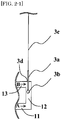
- FIG. 2-1 is an enlarged schematic view showing an example of the tubular reaction line 1 into which the temperature sensor 3b of the thermometer 3a is inserted.
- the internal temperature measurement unit 2 has the thermometer 3a and the temperature sensor 3b of the thermometer 3a.
- the internal temperature measurement unit 2 may further include a support 3c for supporting the thermometer 3a.
- the diameter of the thermometer 3a is not particularly limited as long as the thermometer 3a can be inserted into the tubular reaction line 1.
- the diameter of the thermometer 3a is generally 0.1 to 4 mm, and preferably 2 mm or less.
- the temperature sensor 3b (particularly, the tip of the temperature sensor 3b) be installed without touching the wall surface of the tubular reaction line 1.
- the flow reactor 10 desirably includes the internal temperature measurement units 2 at two or more locations (preferably 3 or more locations, and preferably 10 or less locations, more preferably 5 or less locations).
- the provision of a plurality of internal temperature measurement units 2 makes it possible to monitor the temperature of the reaction solution at a plurality of locations of the tubular reaction line 1, whereby the temperature management and control of the tubular reaction line 1 can be more strictly performed.
- the internal temperature measurement unit 2 be provided at least one location in a first half position of the tubular reaction line 1, the first half position corresponding to 50% (preferably 40%, more preferably 30%) of the entire length of the tubular reaction line 1 from an inlet of the tubular reaction line 1.
- the temperature of a reaction solution rises immediately after the start of a reaction due to a heat of reaction. Therefore, if the internal temperature measurement unit 2 is provided in the first half position of the entire length of the tubular reaction line 1, it becomes possible to strictly perform the temperature management in the reaction solution immediately after the start of the reaction.
- the temperature control of the tubular reaction line 1 can be more precisely performed, whereby the flow reactor 10 has increased safety, and has also improved reaction yield, reaction selectivity, and the like.
- the flow reactor 10 include the internal temperature measurement units 2 at two or more locations, and more than a majority of the internal temperature measurement units 2 be provided in the first half position.
- the provision of a larger number of the internal temperature measurement units 2 in the first half position of the tubular reaction line 1 makes it possible to measure the temperature change of the reaction solution immediately after the start of the reaction at a greater level of detail.
- the internal temperature measurement unit 2 may be provided in a latter half position of the tubular reaction line 1, in addition to the first half position, the latter half position corresponding to 50% (preferably 40%, more preferably 30%) of the entire length of the tubular reaction line 1 from an outlet of the tubular reaction line 1.
- tubular reaction line refers to an elongated hollow tube reactor.
- the cross section of the flow channel of the tubular reaction line 1 is desirably circular.
- the length of the tubular reaction line 1 is preferably 1 cm or more, and more preferably 10 cm or more.
- the upper limit of the length of the tubular reaction line 1 is not particularly limited, and is preferably 500 m or less, and more preferably 300 m or less.
- the length of the tubular reaction line 1 may be appropriately determined according to a retention time of the reaction solution, and the like.
- the shape of the tubular reaction line 1 may be appropriately selected in consideration of the length of the tubular reaction line 1, the installation space of the flow reactor 10, and the like, and is not particularly limited.
- the shape of the tubular reaction line 1 is preferably a curved shape such as a helical shape (coil shape), or a straight shape.
- the curved tubular reaction line 1 especially contributes to space saving of the flow reactor 10.
- a helical axis 20 may be substantially parallel to the direction of gravity or substantially perpendicular to the direction of gravity, and is preferably substantially parallel to the direction of gravity.
- the tubular reaction line 1 be curved and include a straight flow channel 4 in part of the tubular reaction line 1, and the internal temperature measurement unit 2 be positioned in the straight flow channel 4.
- the curved tubular reaction line 1 contributes to space saving of the flow reactor 10.
- the straight flow channel 4 be provided in part of the curved tubular reaction line 1, and the internal temperature measurement unit 2 be provided in the straight flow channel 4. This allows the internal temperature measurement unit 2 not to inhibit the flow of the reaction solution flowing in the tubular reaction line 1 and allows the temperature sensor 3b to hardly touch the wall surface of the tubular reaction line 1.
- the flow channel length of the straight flow channel 4 is desirably long enough to accommodate the temperature sensor 3b.
- the flow channel length of the straight flow channel 4 is, for example, preferably 3 to 10 times, and more preferably 5 to 8 times the diameter of the thermometer 3a.
- the flow channel length of the straight flow channel 4 is, for example, preferably 1 to 100 mm, and more preferably 5 to 50 mm.
- the straight flow channel 4 may be provided substantially parallel to the helical axis 20 (for example, FIG. 1 ), and may be provided along a helical rotation plane.
- the straight flow channel 4 is preferably provided inside, outside or on the circumference (for example, when a helical diameter varies depending on a helical cycle) of the circle drawn by the helix.
- the straight flow channel 4 is preferably provided inside or outside the circle drawn by the helix. The provision of the straight flow channel 4 along the helical rotation plane makes it possible to form the flow channel of the tubular reaction line 1 densely, resulting in space saving of the flow reactor 10.
- the tubular reaction line 1 be helical, and the straight flow channel 4 be substantially parallel to the helical axis 20 of the helical tubular reaction line 1.
- the tubular reaction line 1 is helical, a longer tubular reaction line 1 can be accommodated in a small space.
- a support that supports the tubular reaction line 1 (the raw material feeding units 31 and the discharging unit 32 serve also this function in FIG.
- the tubular reaction line 1 can be easily replaced after the reaction.
- the helical axis 20 of the tubular reaction line 1 is substantially parallel to the direction of gravity, the helical tubular reaction line 1 and the internal temperature measurement units 2 can be installed by being suspended, resulting in a simplified apparatus.
- part of the tubular reaction line 1 include successive three flow channels of an inflow-side flow channel 11, an intermediate flow channel 12, and an outflow-side flow channel 13, and the straight flow channel 4 be the intermediate flow channel 12.
- Forming the intermediate flow channel 12 straight makes the insertion of the thermometer 3a easy.
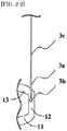
- the shapes of the inflow-side flow channel 11 and the outflow-side flow channel 13 are not particularly limited. Each of the inflow-side flow channel 11 and the outflow-side flow channel 13 may be formed straight as shown in FIG. 2-1 or curved as shown in FIG. 2-2 , and is preferably formed straight. Forming both the inflow-side channel 11 and the outflow-side channel 13 straight makes the apparatus design easier.
- the angles between the above three flow channels are not particularly limited.
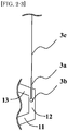
- the angle formed by the inflow-side flow channel 11 and the intermediate flow channel 12, and the angle formed by the intermediate flow channel 12 and the outflow-side flow channel 13 may be each, for example, 85 to 95 degrees as shown in FIG. 2-1 (that is, approximately 90 degrees), may be each greater than 95 degrees as shown in FIG. 2-3 , or may be each less than 85 degrees, and are each preferably 85 to 95 degrees, and more preferably 90 degrees. Adjusting the angles within the above range makes the apparatus design easier.
- the flow direction of the reaction solution may be either a direction A in which the temperature sensor 3b is located upstream and a thermometer insertion portion 3d is located downstream, or a direction B in which the thermometer insertion portion 3d is located upstream and the temperature sensor 3b is located downstream.
- the flow channel indicated as the inflow-side flow channel 11 acts as an outflow-side flow channel
- the flow channel indicated as the outflow-side flow channel 13 acts as an inflow-side flow channel.
- the reaction solution flows from the front toward the temperature sensor 3b, and therefore the direction A is suitable for more accurate temperature measurement.
- the thermometer insertion portion 3d refers to a portion of the thermometer 3a that is present in the tubular reaction line 1, the portion being situated farthest from the tip of the thermometer 3a that is present in the tubular reaction line 1.
- the flow channel lengths of the inflow-side flow channel 11 and the outflow-side flow channel 13 are each preferably 5 to 100 mm, and more preferably 10 to 50 mm in terms of apparatus design.
- the equivalent diameter of the flow channel of the tubular reaction line 1 is preferably 0.1 mm or more, more preferably 1.0 mm or more, and further preferably 1.5 mm or more, and is preferably 50 mm or less, more preferably 20 mm or less, and further preferably 15 mm or less.
- the equivalent diameter of the flow channel of the tubular reaction line 1 may be uniform throughout the whole tubular reaction line 1 or may be changed in the middle of the tubular reaction line 1. If the equivalent diameter of the flow channel of the tubular reaction line 1 is uniform, the reaction proceeds evenly without the flow of the reaction solution being hindered. On the other hand, taking various conditions such as mixing performance and heat removal efficiency into consideration, the equivalent diameter of the flow channel of the tubular reaction line 1 may be changed in the middle of the tubular reaction line 1.
- the equivalent diameter of the flow channel may be changed at an arbitrary position, the number of times of changing the equivalent diameter of the flow channel is not limited, and the equivalent diameter of the flow channel may be changed once or twice or more as necessary.
- the equivalent diameter of the flow channel may be gradually changed or may be greatly changed with a certain point being as the border.
- the equivalent diameter of the flow channel may be smaller or may be larger than the equivalent diameter of the flow channel on the upstream side, and may be appropriately designed according to the reaction.
- the design of the flow channel is not limited to the following example. However, for example, since the mixing efficiency improves as the equivalent diameter of the flow channel of the tubular reaction line 1 decreases, it is also possible that the equivalent diameter of the flow channel of the tubular reaction line 1 immediately after the start of the reaction (that is, immediately after the mixing unit 36 described later) is made small, and after sufficient mixing, the equivalent diameter of the flow channel of the tubular reaction line 1 is made large.
- the tube thickness of the tubular reaction line 1 may be uniform throughout the whole tubular reaction line 1 or may be changed in the middle of the tubular reaction line 1. If the tube thickness of the tubular reaction line 1 is made thin, the structure in which heat can be easily removable, and heat removal efficiency improves. If the tube thickness of the tubular reaction line 1 is thin, the cooling efficiency also increases.
- the tube thickness of the tubular reaction line 1 refers to the thickness of the material forming the flow channel of the tubular reaction line 1.
- the outer diameter of the tubular reaction line 1 may be uniform throughout the whole tubular reaction line 1 or may be changed in the middle of the tubular reaction line 1. Since the heat removal efficiency improves as the outer diameter of the tubular reaction line 1 decreases, for example, for a portion requiring a precise temperature control, both the equivalent diameter of the flow channel of the tubular reaction line 1 and the outside diameter of the tubular reaction line 1 may be decreased. Alternatively, by increasing only the equivalent diameter of the flow channel and making the outer diameter of the tubular reaction line 1 uniform, the tube thickness of the tubular reaction line 1 is made thin, so that the structure in which can be heat easily escapes can be obtained.
- the outer diameter of the tubular reaction line 1 in the present invention refers to the outer equivalent diameter of the tubular reaction line 1.
- the inner wall of the tubular reaction line 1 is preferably formed of, for example, inorganic substances such as metals, silicon, glass and ceramic, or organic substances such as resins according to the characteristics of the reaction product.
- the tubular reaction line 1 has an inlet for introducing a raw material into the tubular reaction line 1 and an outlet for discharging a product produced in the tubular reaction line 1 to the outside of the tubular reaction line 1.
- the installation positions of the inlet and the outlet are not particularly limited.
- the inlet may be placed at the same height as the outlet, at a position higher than the position of the outlet, or at a position lower than the position of the outlet. If the inlet is placed at a position lower than the position of the outlet, bubbles contained in the reaction solution are entrained by the flow of the reaction solution and discharged from the upper part of the tubular reaction line 1, so that bubbles hardly adhere to the inner wall of the tubular reaction line 1. As a result, the raw materials in the reaction solution can be efficiently brought into contact with each other.
- the flow reactor 10 according to the present invention desirably further includes a raw material feeding unit 31 provided on the upstream side of the tubular reaction line 1.
- the raw material feeding unit 31 corresponds to a unit to feed a raw material to be used in the tubular reaction line 1.
- the flow reactor 10 may have two or more (for example, three) raw material feeding units 31 according to a reaction method.
- raw materials fed from either one or both raw material feeding units 31 may be a resultant product obtained by preliminarily mixing other raw materials in a premixer and then reacting them as necessary.
- the reaction solution discharged from the tubular reaction line 1 may be used as a raw material for a subsequent flow reactor 10.
- the reaction raw materials (including the preliminary reactant) are fed into the tubular reaction line 1 through these raw material feeding units 31.
- the reaction raw materials are usually fed in the form of gas or liquid (including solution).
- the flow reactor 10 desirably further includes a mixing unit 36 to mix raw materials fed from the raw material feeding units 31.
- the mixing unit 36 is provided between the ends of the two or more raw material feeding units 31 and the inlet of the tubular reaction line 1.
- the mixed solution obtained in the mixing unit 36 is fed as a reaction solution into the tubular reaction line 1 through the inlet of the tubular reaction line 1.
- the mixing unit 36 is preferably a tube, and the inner diameter of the tube is preferably 0.01 mm or more and 50 mm or less.
- a known mixer may be provided in the mixing unit 36 in order to sufficiently stir the raw materials.
- Examples of such a mixer include a T-shape mixer, a Y-shape mixer, a static mixer, a helix-type mixer, and the like.
- the reaction raw materials are preferably fed by a feed control unit such as a diaphragm pump.
- the number of feed control units is not particularly limited and may be equal to or greater than or less than the number of the raw material feeding units 31.
- the feed control unit is not limited to a pump, and for example, a pressurized container to charge a reaction raw material can also be used as the feed control unit.
- the raw material feeding unit 31 is preferably a tube (tubular), and the inner diameter of the tube is preferably 0.01 mm or more, more preferably 0.1 mm or more, and preferably 50 mm or less.
- the flow reactor 10 desirably further includes temperature adjustment equipment 33 to perform temperature control of the tubular reaction line 1.
- the flow reactor has a larger specific surface area and better heat transfer performance as compared with those of a batch reactor, and thus temperature control can be performed quickly. Therefore, the provision of the temperature adjustment equipment 33 allows the temperature management of the reaction solution to be quickly performed. Due to the presence of the temperature adjustment equipment 33, reaction yields and quality can be improved in a system that initiates a reaction by heat, a system that lowers a temperature to suppress a by-product formation, and the like.
- the temperature adjustment equipment 33 may perform the temperature control based on a temperature measured in the internal temperature measurement unit 2.
- the temperature of the reaction solution in the tubular reaction line 1 is directly measured, and therefore the temperature of the reaction solution is accurately measured.
- the temperature control of the tubular reaction line 1 can be performed more strictly.
- the temperature adjustment equipment 33 is not limited to a specific embodiment as long as the temperature of the tubular reaction line 1 can be controlled.
- Examples of the specific embodiment of the temperature adjustment equipment 33 include an embodiment in which part or all of the tubular reaction line 1 is placed in a fluid of which temperature can be adjusted; and an embodiment in which part or all of the tubular reaction line 1 is configured in a multilayer structure (for example, a two-layer tube or the like) to adjust the temperature from the inner side, the outer side, or both sides of the layers.
- the embodiment in which the tubular reaction line 1 is placed in a fluid of which temperature can be adjusted is desirable. That is, the temperature adjustment equipment 33 desirably includes a fluid 34 that is contactable with part or all of the tubular reaction line 1, and a container 35 to contain the fluid 34, and controls a temperature and/or a feeding amount of the fluid 34 based on a temperature measured in the internal temperature measurement unit 2. By directly controlling the temperature and the feeding amount of the fluid 34 that is contactable with part or all of the tubular reaction line 1, the temperature of the tubular reaction line 1 in contact with the fluid 34 can be adjusted uniformly.
- Examples of the fluid 34 that is contactable with part or all of the tubular reaction line 1 include water; an alcohol containing at least one alcohol selected from methanol, ethanol, ethylene glycol, propylene glycol, and the like, or aqueous solutions thereof; an acidic aqueous solution containing at least one acid selected from hydrochloric acid, sulfuric acid, phosphoric acid, acetic acid, citric acid, and the like; an alkaline aqueous solution containing at least one base selected from sodium hydroxide, potassium carbonate, and sodium hydrogen carbonate; an oxidizing aqueous solution such as a hydrogen peroxide solution, sodium hypochlorite aqueous solution, sodium chlorite aqueous solution or the like; and a reducing aqueous solution such as a sodium thiosulfate aqueous solution, sodium sulfite aqueous solution or the like.
- the state of the fluid 34 is not particularly limited, and may be either gas or liquid depending on the temperature of the fluid 34
- a toxic substance such as acrylonitrile, acrolein, sulfurous acid gas, arsine, ammonia, carbon monoxide, chlorine, chloromethine, chloroprene, arsenic pentafluoride, phosphorus pentafluoride, ethylene oxide, nitrogen trifluoride, boron trifluoride, phosphorus trifluoride, hydrogen cyanide, diethylamine, disilane, sulfur tetrafluoride, silicon tetrafluoride, diborane, hydrogen selenide, trimethylamine, carbon disulfide, fluorine, bromomethyl, phosgene, phosphine, monogermane, monosilane, monomethylamine, or hydrogen sulfide in the tubular reaction line 1, and even if a solution in the tubular reaction line 1 leaks out of the tubular reaction line 1, the fluid 34 such as water, an acidic aqueous solution, an alkaline aqueous
- the temperature and/or the feeding amount of the fluid 34 be controlled based on a program processing using a temperature measured in the internal temperature measurement unit 2 as input information.
- the temperature measured in the internal temperature measurement unit 2 can be fed back to the temperature adjustment equipment 33 more quickly by the introduction of the program processing, and therefore the temperature of the reaction solution in the tubular reaction line 1 can be controlled more strictly.
- the flow reactor 10 may be provided with an impeller 37 to stir the fluid 34.
- thermo adjustment equipment 33 It is also possible to adjust the temperatures of the raw material feeding unit 31 and/or the mixing unit 36 by the temperature adjustment equipment 33.
- Examples of an embodiment of adjusting the temperatures of the raw material feeding unit 31 and/or the mixing unit 36 by the temperature adjustment equipment 33 include, as in the tubular reaction line 1, an embodiment in which the raw material feeding unit 31 and/or the mixing unit 36 are placed in a fluid of which temperature can be adjusted; and an embodiment in which the raw material feeding unit 31 and/or the mixing unit 36 are configured in a multilayer structure (for example, a two-layer tube or the like) to adjust the temperature from the inner side, the outer side, or both sides of the layers.
- a multilayer structure for example, a two-layer tube or the like
- the flow reactor 10 further include a discharge unit 32 to discharge a reaction product produced in the tubular reaction line 1. Not only the reaction product produced in the tubular reaction line 1 but also unreacted raw materials flow through the discharge unit 32.
- the discharge unit 32 is desirably connected to the outlet of the tubular reaction line 1.
- the discharge unit 32 is preferably a tube, and the inner diameter of the tube is preferably 0.01 mm or more, more preferably 0.1 mm or more, and preferably 50 mm or less. It is desirable that the reaction solution collected from the discharge unit 32 be appropriately processed thereafter.
- the raw material feeding unit 31, the mixing unit 36 and the discharge unit 32 are preferably made from a metal such as stainless steel, Hastelloy, titanium, copper, nickel, or aluminum; an inorganic material such as glass or ceramic; or a resin such as PEEK resin, silicone resin, or fluororesin. Electrical conductivity may be imparted to the resin. From the viewpoint of corrosion resistance, heat resistance and durability, the metal, particularly Hastelloy, is preferable.
- the raw material feeding unit 31, the mixing unit 36, and the discharge unit 32 may have either a single-layer structure or a multilayer structure. From the viewpoint of prevention of liquid leakage, at least one or all of the raw material feeding unit 31, the mixing unit 36, and the discharge unit 32 desirably have a multilayer structure.
- the raw material feeding units 31 are preferably respectively connected to raw material storage containers (not shown) to store respective raw materials.
- the raw material feeding units 31 are preferably respectively provided with feed control units (not shown), and the mixed solution flows in the tubular reaction line 1 by the pressure generated by these feed control units.
- the reaction solution discharged from the tubular reaction line 1 is temporarily stored in a reaction solution storage container.
- the flow reactor 10 of the present invention can be used, for example, for a chemical reaction operation, an extraction operation, a separation operation, a purification operation, or the like, which is an example of a chemical reaction operation for a fluid. That is, the present invention also includes a manufacturing facility including the flow reactor 10 described above.
- the flow reactor 10 of the present invention various chemical reactions can be performed, and there is no particular limitation on the chemical reaction. Since a reaction in the flow reactor 10 is performed in a highly closed system, the flow reactor 10 can be also applied to a reaction using a hazardous chemicals such as acrylonitrile, acrolein, sulfurous acid gas, arsine, ammonia, carbon monoxide, chlorine, chloromethine, chloroprene, arsenic pentafluoride, phosphorus pentafluoride, ethylene oxide, nitrogen trifluoride, boron trifluoride, phosphorus trifluoride, hydrogen cyanide, diethylamine, disilane, sulfur tetrafluoride, silicon tetrafluoride, diborane, hydrogen selenide, trimethylamine, carbon disulfide, fluorine, bromomethyl, phosgene, phosphine, monogermane, monosilane, monomethylamine, or hydrogen sulfide.
- the temperature in the tubular reaction line 1 during a reaction is not particularly limited as long as it is equal to or lower than the boiling point of the reaction solvent and equal to or higher than the freezing point of the reaction solvent, and preferably -80°C or higher, more preferably -60°C or higher, further preferably -40°C or higher, preferably 200°C or lower, more preferably 180°C or lower, and further preferably 160°C or lower.
- the flow rate of the reaction solution in the tubular reaction line 1 is preferably 2 m/s or less, more preferably 1 m/s or less, and further preferably 0.8 m/s or less.
- reaction time is preferably 60 minutes or less, more preferably 30 minutes or less, further preferably 15 minutes or less.
Landscapes
- Chemical & Material Sciences (AREA)
- Organic Chemistry (AREA)
- Chemical Kinetics & Catalysis (AREA)
- Physical Or Chemical Processes And Apparatus (AREA)
- Devices And Processes Conducted In The Presence Of Fluids And Solid Particles (AREA)
Abstract
Description
- The present invention relates to a flow reactor and a manufacturing facility comprising the flow reactor. More particularly, the present invention relates to a flow reactor comprising a tubular reaction line, wherein the flow reactor further comprises an internal temperature measurement unit provided at one or more locations of the tubular reaction line, the internal temperature measurement unit comprises a thermometer with a temperature sensor, and the temperature sensor is inserted into the tubular reaction line.
- A micro-flow reactor is a chemical reaction apparatus generally comprising a microchannel in the order of submillimeter as a reaction field. The micro-flow reactor has attracted attention in recent years because it has specific effects, due to the micro reaction field, such as high-speed mixing performance (for example, when two liquids are mixed in a micro reaction space, the substance diffusion distance in the two liquids decreases, resulting in shortening the time of mass transfer movement), heat removal efficiency (for example, since the reaction field of the micro-flow reactor is very small, thermal efficiency is extremely high and temperature control is easy), reaction control performance, interface control performance, or the like. In addition, it is expected that the technology of the micro-flow reactor provides various effects such as improved safety and significantly reduced cost of equipment along with downsizing of the whole process, process intensification (micro in macro) by incorporating into existing processes, and production of substances that could not be produced by an existing production method.
- However, the micro-flow reactor has a problem that only a limited amount can be processed at a time. Therefore, process development of a flow reactor is being carried out for the purpose of providing practical process by increasing processing amount. The flow reactor is a chemical reaction apparatus in which the diameter of a flow channel is enlarged to the order of millimeters to centimeters to the extent that the characteristics of the micro-flow reactor are not impaired to enhance the operability. The flow reactor is mainly composed of a raw material feeding line, a reaction unit, and an operation control unit (such as, for example, Patent Document 1).
- Patent Document 1:
JP 2013-543021 (A - Conventionally, the temperature of a flow reactor has been controlled only by measuring the temperature of the outer wall of the flow reactor or the temperature of temperature adjustment equipment of the flow reactor without usually measuring an internal temperature in the flow reactor. However, as a result of the studies of the inventors, it was found that, although a flow reactor has a large heat transfer area relative to its capacity and thus has advantages of high heat removal efficiency and high heating efficiency, the flow reactor has difficulty of local control of heat there if the reaction locally proceeds due to its high heat removal efficiency and high heating efficiency. In particular, when a tubular reactor is used, and the flow channel is long, it is difficult to accurately determine the internal temperature, and it is impossible to detect a locally proceeding reaction. In the recent precision synthesis, the demand for strict control of the internal temperature of a flow reactor is increasing.
- Under such circumstances, an object of the present invention is to provide a flow reactor including a tubular reaction line in which a temperature in the tubular reaction line can be more accurately measured.
- As a result of intensive studies for achieving the above object, the inventors have found that a flow reactor including a tubular reaction line, wherein the flow reactor further includes an internal temperature measurement unit provided at one or more locations of the tubular reaction line, the internal temperature measurement unit includes a thermometer with a temperature sensor, and the temperature sensor is inserted into the tubular reaction line can achieve the above object. The invention has been made based on such a finding.
- That is, the flow reactor according to the present invention has one or more features described below.
- [1] A flow reactor comprising a tubular reaction line,
wherein the flow reactor further comprises an internal temperature measurement unit provided at one or more locations of the tubular reaction line,
the internal temperature measurement unit comprises a thermometer with a temperature sensor, and
the temperature sensor is inserted into the tubular reaction line. - [2] The flow reactor according to [1],
wherein the tubular reaction line is curved and comprises a straight flow channel in part of the tubular reaction line, and
the internal temperature measurement unit is positioned in the straight flow channel. - [3] The flow reactor according to [2],
wherein the tubular reaction line is helical, and
the straight flow channel is substantially parallel to a helical axis of the helical tubular reaction line. - [4] The flow reactor according to [3],
wherein part of the tubular reaction line comprises successive three flow channels of an inflow-side flow channel, an intermediate flow channel, and an outflow-side flow channel,
the straight flow channel is the intermediate flow channel, and
the intermediate flow channel is substantially parallel to the helical axis of the helical tubular reaction line. - [5] The flow reactor according to [4], wherein each of the inflow-side flow channel and the outflow-side flow channel is formed straight.
- [6] The flow reactor according to any one of [1] to [5], wherein the internal temperature measurement unit is provided at least one location in a first half position of the tubular reaction line, the first half position corresponding to 50% of an entire length of the tubular reaction line from an inlet of the tubular reaction line.
- [7] The flow reactor according to [6], wherein the flow reactor comprises the internal temperature measurement units at two or more locations, and more than a majority of the internal temperature measurement units are provided in the first half position.
- [8] The flow reactor according to any one of [1] to [7], wherein the tubular reaction line has a flow channel with an equivalent diameter of 0.1 mm or more and 50 mm or less.
- [9] The flow reactor according to any one of [1] to [8] further comprising:
- a raw material feeding unit provided on an upstream side of the tubular reaction line;
- a discharge unit to discharge a reaction product produced in the tubular reaction line; and
- temperature adjustment equipment to perform temperature control of the tubular reaction line.
- [10] The flow reactor according to [9], wherein the temperature adjustment equipment performs the temperature control based on a temperature measured in the internal temperature measurement unit.
- [11] The flow reactor according to [9] or [10],
wherein the temperature adjustment equipment comprises a fluid that is contactable with part or all of the tubular reaction line, and a container to contain the fluid, and
the temperature adjustment equipment controls a temperature and/or a feeding amount of the fluid based on a temperature measured in the internal temperature measurement unit. - [12] The flow reactor according to [11], wherein the temperature and/or the feeding amount of the fluid are controlled based on a program processing using a temperature measured in the internal temperature measurement unit as input information.
- [13] The flow reactor according to any one of [9] to [12], wherein the flow reactor comprises two or more of the raw material feeding units and further comprises a mixing unit to mix raw materials fed from the two or more raw material feeding units, and
the mixing unit is provided between ends of the two or more raw material feeding units and the inlet of the tubular reaction line. - [14] A manufacturing facility comprising the flow reactor according to any one of [1] to [13].
- According to the present invention, a novel flow reactor capable of measuring the internal temperature is provided.
-
-
FIG. 1 is a schematic view showing an example of the configuration of a flow reactor adopted in the present invention; -
FIG. 2-1 is an enlarged schematic view showing an example of a tubular reaction line 1 into which atemperature sensor 3b of athermometer 3a is inserted; -
FIG. 2-2 is an enlarged schematic view showing another example of a tubular reaction line 1 into which atemperature sensor 3b of athermometer 3a is inserted; -
FIG. 2-3 is an enlarged schematic view showing another example of a tubular reaction line 1 into which atemperature sensor 3b of athermometer 3a is inserted; - Hereinafter, the present invention will be described in more detail with reference to the drawings as necessary.
-
FIG. 1 is a schematic view showing an example of the configuration of aflow reactor 10 adopted in the present invention, and the example shown inFIG. 1 is the most basic example. As shown in the basic example ofFIG. 1 , theflow reactor 10 according to the present invention includes a tubular reaction line 1 and an internaltemperature measurement unit 2 provided at one or more locations of the tubular reaction line 1. The internaltemperature measurement unit 2 includes athermometer 3a with atemperature sensor 3b, and thetemperature sensor 3b is inserted into the tubular reaction line 1. In theflow reactor 10, a reaction proceeds while a solution is transferred through the tubular reaction line 1. According to the present invention, thetemperature sensor 3b of thethermometer 3a is inserted into the tubular reaction line 1, and thus it becomes possible to directly measure the temperature of a reaction solution, whereby the temperature in the tubular reaction line 1 can be more accurately measured. - The
flow reactor 10 according to the present invention may further include a rawmaterial feeding unit 31 provided on an upstream side of the tubular reaction line 1, adischarge unit 32 to discharge a reaction product produced in the tubular reaction line 1, andtemperature adjustment equipment 33 to perform temperature control of the tubular reaction line 1. The provision of thetemperature adjustment equipment 33 in theflow reactor 10 allows the temperature management of the tubular reaction line 1. - The present invention also includes a manufacturing facility including the
flow reactor 10. - In the present specification, the "flow reactor" refers to a chemical reaction apparatus having a narrow flow channel of the order of micrometers to centimeters as a reaction field. The reaction field is minimized in the flow reactor, and therefore, the flow reactor has features that heat and substances can be transferred at high speed, rapid mixing is possible, a reaction time can be controlled by a flow channel length, and the like, which cannot be achieved using ordinary batch reactors. In terms of the process, the flow reactor has features that facilities can be downsized, resulting in reduced cost for facilities, the amount of energy used can be minimized, resulting in reduced variable costs, the amount of hazardous substances used can be extremely reduced when handling hazardous substances, resulting in a dramatic increase in safety, and the like.
-
FIG. 2-1 is an enlarged schematic view showing an example of the tubular reaction line 1 into which thetemperature sensor 3b of thethermometer 3a is inserted. As shown inFIG. 2-1 , the internaltemperature measurement unit 2 has thethermometer 3a and thetemperature sensor 3b of thethermometer 3a. The internaltemperature measurement unit 2 may further include asupport 3c for supporting thethermometer 3a. - The diameter of the
thermometer 3a is not particularly limited as long as thethermometer 3a can be inserted into the tubular reaction line 1. The diameter of thethermometer 3a is generally 0.1 to 4 mm, and preferably 2 mm or less. - In order to measure the temperature of the reaction solution with high sensitivity and more accurately, it is preferred that the
temperature sensor 3b (particularly, the tip of thetemperature sensor 3b) be installed without touching the wall surface of the tubular reaction line 1. - The
flow reactor 10 according to the present invention desirably includes the internaltemperature measurement units 2 at two or more locations (preferably 3 or more locations, and preferably 10 or less locations, more preferably 5 or less locations). The provision of a plurality of internaltemperature measurement units 2 makes it possible to monitor the temperature of the reaction solution at a plurality of locations of the tubular reaction line 1, whereby the temperature management and control of the tubular reaction line 1 can be more strictly performed. - In the
flow reactor 10 according to the present invention, it is desirable that the internaltemperature measurement unit 2 be provided at least one location in a first half position of the tubular reaction line 1, the first half position corresponding to 50% (preferably 40%, more preferably 30%) of the entire length of the tubular reaction line 1 from an inlet of the tubular reaction line 1. In a general chemical reaction, the temperature of a reaction solution rises immediately after the start of a reaction due to a heat of reaction. Therefore, if the internaltemperature measurement unit 2 is provided in the first half position of the entire length of the tubular reaction line 1, it becomes possible to strictly perform the temperature management in the reaction solution immediately after the start of the reaction. As a result, the temperature control of the tubular reaction line 1 can be more precisely performed, whereby theflow reactor 10 has increased safety, and has also improved reaction yield, reaction selectivity, and the like. - It is desirable that the
flow reactor 10 according to the present invention include the internaltemperature measurement units 2 at two or more locations, and more than a majority of the internaltemperature measurement units 2 be provided in the first half position. The provision of a larger number of the internaltemperature measurement units 2 in the first half position of the tubular reaction line 1 makes it possible to measure the temperature change of the reaction solution immediately after the start of the reaction at a greater level of detail. - The internal
temperature measurement unit 2 may be provided in a latter half position of the tubular reaction line 1, in addition to the first half position, the latter half position corresponding to 50% (preferably 40%, more preferably 30%) of the entire length of the tubular reaction line 1 from an outlet of the tubular reaction line 1. - In the present specification, the "tubular reaction line" refers to an elongated hollow tube reactor. The cross section of the flow channel of the tubular reaction line 1 is desirably circular.
- The length of the tubular reaction line 1 is preferably 1 cm or more, and more preferably 10 cm or more. The upper limit of the length of the tubular reaction line 1 is not particularly limited, and is preferably 500 m or less, and more preferably 300 m or less. The length of the tubular reaction line 1 may be appropriately determined according to a retention time of the reaction solution, and the like.
- The shape of the tubular reaction line 1 may be appropriately selected in consideration of the length of the tubular reaction line 1, the installation space of the
flow reactor 10, and the like, and is not particularly limited. The shape of the tubular reaction line 1 is preferably a curved shape such as a helical shape (coil shape), or a straight shape. The curved tubular reaction line 1 especially contributes to space saving of theflow reactor 10. When the tubular reaction line 1 is helical, ahelical axis 20 may be substantially parallel to the direction of gravity or substantially perpendicular to the direction of gravity, and is preferably substantially parallel to the direction of gravity. By allowing thehelical axis 20 to be substantially parallel to the direction of gravity, the helical tubular reaction line 1 can be installed by being suspended as shown inFIG. 1 , and the tubular reaction line 1 after the reaction can be replaced easily. - In the
flow reactor 10 according to the present invention, it is desirable that the tubular reaction line 1 be curved and include a straight flow channel 4 in part of the tubular reaction line 1, and the internaltemperature measurement unit 2 be positioned in the straight flow channel 4. As described above, the curved tubular reaction line 1 contributes to space saving of theflow reactor 10. However, if the entirety of the curved tubular reaction line 1 is curved, it is difficult to insert thetemperature sensor 3b of thethermometer 3a into the tubular reaction line 1, and thetemperature sensor 3b tends to touch the wall surface of the tubular reaction line 1, resulting in difficulty in accurately measuring the temperature of the reaction solution. Therefore, it is preferred that the straight flow channel 4 be provided in part of the curved tubular reaction line 1, and the internaltemperature measurement unit 2 be provided in the straight flow channel 4. This allows the internaltemperature measurement unit 2 not to inhibit the flow of the reaction solution flowing in the tubular reaction line 1 and allows thetemperature sensor 3b to hardly touch the wall surface of the tubular reaction line 1. - The flow channel length of the straight flow channel 4 is desirably long enough to accommodate the
temperature sensor 3b. The flow channel length of the straight flow channel 4 is, for example, preferably 3 to 10 times, and more preferably 5 to 8 times the diameter of thethermometer 3a. Specifically, the flow channel length of the straight flow channel 4 is, for example, preferably 1 to 100 mm, and more preferably 5 to 50 mm. - When the tubular reaction line 1 is helical, the straight flow channel 4 may be provided substantially parallel to the helical axis 20 (for example,
FIG. 1 ), and may be provided along a helical rotation plane. When the straight flow channel 4 is provided substantially parallel to thehelical axis 20, the straight flow channel 4 is preferably provided inside, outside or on the circumference (for example, when a helical diameter varies depending on a helical cycle) of the circle drawn by the helix. When the straight flow channel 4 is provided along the helical rotation plane, the straight flow channel 4 is preferably provided inside or outside the circle drawn by the helix. The provision of the straight flow channel 4 along the helical rotation plane makes it possible to form the flow channel of the tubular reaction line 1 densely, resulting in space saving of theflow reactor 10. - In the
flow reactor 10 according to the present invention, it is more desirable that the tubular reaction line 1 be helical, and the straight flow channel 4 be substantially parallel to thehelical axis 20 of the helical tubular reaction line 1. When the tubular reaction line 1 is helical, a longer tubular reaction line 1 can be accommodated in a small space. Furthermore, by allowing the straight flow channel 4 to be substantially parallel to thehelical axis 20 of the helical tubular reaction line 1, as shown inFIG. 1 , a support that supports the tubular reaction line 1 (the rawmaterial feeding units 31 and the dischargingunit 32 serve also this function inFIG. 1 ) and a support that supports thethermometer 3a are attached to theflow reactor 10 without crossing each other, and therefore, the tubular reaction line 1 can be easily replaced after the reaction. In particular, when thehelical axis 20 of the tubular reaction line 1 is substantially parallel to the direction of gravity, the helical tubular reaction line 1 and the internaltemperature measurement units 2 can be installed by being suspended, resulting in a simplified apparatus. - As shown in
FIG. 2-1 , it is desirable that part of the tubular reaction line 1 include successive three flow channels of an inflow-side flow channel 11, anintermediate flow channel 12, and an outflow-side flow channel 13, and the straight flow channel 4 be theintermediate flow channel 12. Forming theintermediate flow channel 12 straight makes the insertion of thethermometer 3a easy. In particular, it is preferred that theintermediate flow channel 12 be substantially parallel to thehelical axis 20 of the helical tubular reaction line 1 since such anintermediate flow channel 12 does not interfere with the replacement of the tubular reaction line 1, and as a result, the replacement can be easily performed. - The shapes of the inflow-
side flow channel 11 and the outflow-side flow channel 13 are not particularly limited. Each of the inflow-side flow channel 11 and the outflow-side flow channel 13 may be formed straight as shown inFIG. 2-1 or curved as shown inFIG. 2-2 , and is preferably formed straight. Forming both the inflow-side channel 11 and the outflow-side channel 13 straight makes the apparatus design easier. - The angles between the above three flow channels are not particularly limited. The angle formed by the inflow-
side flow channel 11 and theintermediate flow channel 12, and the angle formed by theintermediate flow channel 12 and the outflow-side flow channel 13 may be each, for example, 85 to 95 degrees as shown inFIG. 2-1 (that is, approximately 90 degrees), may be each greater than 95 degrees as shown inFIG. 2-3 , or may be each less than 85 degrees, and are each preferably 85 to 95 degrees, and more preferably 90 degrees. Adjusting the angles within the above range makes the apparatus design easier. - In the above-described tubular reaction line 1, as shown in
FIG. 2-1 , the flow direction of the reaction solution may be either a direction A in which thetemperature sensor 3b is located upstream and athermometer insertion portion 3d is located downstream, or a direction B in which thethermometer insertion portion 3d is located upstream and thetemperature sensor 3b is located downstream. However, when the flow direction of the reaction solution is in the direction B inFIG. 2-1 , the flow channel indicated as the inflow-side flow channel 11 acts as an outflow-side flow channel, and the flow channel indicated as the outflow-side flow channel 13 acts as an inflow-side flow channel. In particular, in the direction A, the reaction solution flows from the front toward thetemperature sensor 3b, and therefore the direction A is suitable for more accurate temperature measurement. Thethermometer insertion portion 3d refers to a portion of thethermometer 3a that is present in the tubular reaction line 1, the portion being situated farthest from the tip of thethermometer 3a that is present in the tubular reaction line 1. - The flow channel lengths of the inflow-
side flow channel 11 and the outflow-side flow channel 13 are each preferably 5 to 100 mm, and more preferably 10 to 50 mm in terms of apparatus design. - In view of pressure drop and processing amount, the equivalent diameter of the flow channel of the tubular reaction line 1 is preferably 0.1 mm or more, more preferably 1.0 mm or more, and further preferably 1.5 mm or more, and is preferably 50 mm or less, more preferably 20 mm or less, and further preferably 15 mm or less.
- In the present invention, the "equivalent diameter of the flow channel" indicates a diameter of a circular tube regarded as equivalent to the cross section of the flow channel. That is, the equivalent diameter De of the flow channel is represented by the following formula (i):

- The equivalent diameter of the flow channel of the tubular reaction line 1 may be uniform throughout the whole tubular reaction line 1 or may be changed in the middle of the tubular reaction line 1. If the equivalent diameter of the flow channel of the tubular reaction line 1 is uniform, the reaction proceeds evenly without the flow of the reaction solution being hindered. On the other hand, taking various conditions such as mixing performance and heat removal efficiency into consideration, the equivalent diameter of the flow channel of the tubular reaction line 1 may be changed in the middle of the tubular reaction line 1. The equivalent diameter of the flow channel may be changed at an arbitrary position, the number of times of changing the equivalent diameter of the flow channel is not limited, and the equivalent diameter of the flow channel may be changed once or twice or more as necessary. Furthermore, the equivalent diameter of the flow channel may be gradually changed or may be greatly changed with a certain point being as the border. The equivalent diameter of the flow channel may be smaller or may be larger than the equivalent diameter of the flow channel on the upstream side, and may be appropriately designed according to the reaction. The design of the flow channel is not limited to the following example. However, for example, since the mixing efficiency improves as the equivalent diameter of the flow channel of the tubular reaction line 1 decreases, it is also possible that the equivalent diameter of the flow channel of the tubular reaction line 1 immediately after the start of the reaction (that is, immediately after the mixing
unit 36 described later) is made small, and after sufficient mixing, the equivalent diameter of the flow channel of the tubular reaction line 1 is made large. - The tube thickness of the tubular reaction line 1 may be uniform throughout the whole tubular reaction line 1 or may be changed in the middle of the tubular reaction line 1. If the tube thickness of the tubular reaction line 1 is made thin, the structure in which heat can be easily removable, and heat removal efficiency improves. If the tube thickness of the tubular reaction line 1 is thin, the cooling efficiency also increases. The tube thickness of the tubular reaction line 1 refers to the thickness of the material forming the flow channel of the tubular reaction line 1.
- The outer diameter of the tubular reaction line 1 may be uniform throughout the whole tubular reaction line 1 or may be changed in the middle of the tubular reaction line 1. Since the heat removal efficiency improves as the outer diameter of the tubular reaction line 1 decreases, for example, for a portion requiring a precise temperature control, both the equivalent diameter of the flow channel of the tubular reaction line 1 and the outside diameter of the tubular reaction line 1 may be decreased. Alternatively, by increasing only the equivalent diameter of the flow channel and making the outer diameter of the tubular reaction line 1 uniform, the tube thickness of the tubular reaction line 1 is made thin, so that the structure in which can be heat easily escapes can be obtained.
- The outer diameter of the tubular reaction line 1 in the present invention refers to the outer equivalent diameter of the tubular reaction line 1. In the present invention, the "outer equivalent diameter" refers to a diameter of a circular tube regarded as equivalent to the cross section of the tubular reaction line 1. That is, the outer equivalent diameter De' of the tube-type reactor is represented by the following formula (ii):

- The inner wall of the tubular reaction line 1 is preferably formed of, for example, inorganic substances such as metals, silicon, glass and ceramic, or organic substances such as resins according to the characteristics of the reaction product.
- The tubular reaction line 1 has an inlet for introducing a raw material into the tubular reaction line 1 and an outlet for discharging a product produced in the tubular reaction line 1 to the outside of the tubular reaction line 1. The installation positions of the inlet and the outlet are not particularly limited. The inlet may be placed at the same height as the outlet, at a position higher than the position of the outlet, or at a position lower than the position of the outlet. If the inlet is placed at a position lower than the position of the outlet, bubbles contained in the reaction solution are entrained by the flow of the reaction solution and discharged from the upper part of the tubular reaction line 1, so that bubbles hardly adhere to the inner wall of the tubular reaction line 1. As a result, the raw materials in the reaction solution can be efficiently brought into contact with each other.
- The
flow reactor 10 according to the present invention desirably further includes a rawmaterial feeding unit 31 provided on the upstream side of the tubular reaction line 1. The rawmaterial feeding unit 31 corresponds to a unit to feed a raw material to be used in the tubular reaction line 1. - The
flow reactor 10 according to the present invention may have two or more (for example, three) rawmaterial feeding units 31 according to a reaction method. When theflow reactor 10 have two or more rawmaterial feeding units 31, raw materials fed from either one or both rawmaterial feeding units 31 may be a resultant product obtained by preliminarily mixing other raw materials in a premixer and then reacting them as necessary. Although not shown, the reaction solution discharged from the tubular reaction line 1 may be used as a raw material for asubsequent flow reactor 10. The reaction raw materials (including the preliminary reactant) are fed into the tubular reaction line 1 through these rawmaterial feeding units 31. The reaction raw materials are usually fed in the form of gas or liquid (including solution). - When two or more raw
material feeding units 31 are provided, theflow reactor 10 according to the present invention desirably further includes a mixingunit 36 to mix raw materials fed from the rawmaterial feeding units 31. When the mixingunit 36 is present, the mixingunit 36 is provided between the ends of the two or more rawmaterial feeding units 31 and the inlet of the tubular reaction line 1. The mixed solution obtained in the mixingunit 36 is fed as a reaction solution into the tubular reaction line 1 through the inlet of the tubular reaction line 1. The mixingunit 36 is preferably a tube, and the inner diameter of the tube is preferably 0.01 mm or more and 50 mm or less. - A known mixer may be provided in the mixing
unit 36 in order to sufficiently stir the raw materials. Examples of such a mixer include a T-shape mixer, a Y-shape mixer, a static mixer, a helix-type mixer, and the like. - In the raw
material feeding unit 31, the reaction raw materials are preferably fed by a feed control unit such as a diaphragm pump. The number of feed control units is not particularly limited and may be equal to or greater than or less than the number of the rawmaterial feeding units 31. The feed control unit is not limited to a pump, and for example, a pressurized container to charge a reaction raw material can also be used as the feed control unit. - The raw
material feeding unit 31 is preferably a tube (tubular), and the inner diameter of the tube is preferably 0.01 mm or more, more preferably 0.1 mm or more, and preferably 50 mm or less. - The
flow reactor 10 according to the present invention desirably further includestemperature adjustment equipment 33 to perform temperature control of the tubular reaction line 1. The flow reactor has a larger specific surface area and better heat transfer performance as compared with those of a batch reactor, and thus temperature control can be performed quickly. Therefore, the provision of thetemperature adjustment equipment 33 allows the temperature management of the reaction solution to be quickly performed. Due to the presence of thetemperature adjustment equipment 33, reaction yields and quality can be improved in a system that initiates a reaction by heat, a system that lowers a temperature to suppress a by-product formation, and the like. - In the
flow reactor 10 according to the present invention, thetemperature adjustment equipment 33 may perform the temperature control based on a temperature measured in the internaltemperature measurement unit 2. In the internaltemperature measurement unit 2, the temperature of the reaction solution in the tubular reaction line 1 is directly measured, and therefore the temperature of the reaction solution is accurately measured. By feeding the accurately measured temperature of the reaction solution back to thetemperature adjustment equipment 33, the temperature control of the tubular reaction line 1 can be performed more strictly. - The
temperature adjustment equipment 33 is not limited to a specific embodiment as long as the temperature of the tubular reaction line 1 can be controlled. Examples of the specific embodiment of thetemperature adjustment equipment 33 include an embodiment in which part or all of the tubular reaction line 1 is placed in a fluid of which temperature can be adjusted; and an embodiment in which part or all of the tubular reaction line 1 is configured in a multilayer structure (for example, a two-layer tube or the like) to adjust the temperature from the inner side, the outer side, or both sides of the layers. - For the
temperature adjustment equipment 33 in theflow reactor 10 of the present invention, the embodiment in which the tubular reaction line 1 is placed in a fluid of which temperature can be adjusted is desirable. That is, thetemperature adjustment equipment 33 desirably includes a fluid 34 that is contactable with part or all of the tubular reaction line 1, and acontainer 35 to contain the fluid 34, and controls a temperature and/or a feeding amount of the fluid 34 based on a temperature measured in the internaltemperature measurement unit 2. By directly controlling the temperature and the feeding amount of the fluid 34 that is contactable with part or all of the tubular reaction line 1, the temperature of the tubular reaction line 1 in contact with the fluid 34 can be adjusted uniformly. - Examples of the fluid 34 that is contactable with part or all of the tubular reaction line 1 include water; an alcohol containing at least one alcohol selected from methanol, ethanol, ethylene glycol, propylene glycol, and the like, or aqueous solutions thereof; an acidic aqueous solution containing at least one acid selected from hydrochloric acid, sulfuric acid, phosphoric acid, acetic acid, citric acid, and the like; an alkaline aqueous solution containing at least one base selected from sodium hydroxide, potassium carbonate, and sodium hydrogen carbonate; an oxidizing aqueous solution such as a hydrogen peroxide solution, sodium hypochlorite aqueous solution, sodium chlorite aqueous solution or the like; and a reducing aqueous solution such as a sodium thiosulfate aqueous solution, sodium sulfite aqueous solution or the like. The state of the fluid 34 is not particularly limited, and may be either gas or liquid depending on the temperature of the fluid 34. Using such a
fluid 34 enables easy control of the temperature. - Furthermore, when there exists, for example, a toxic substance such as acrylonitrile, acrolein, sulfurous acid gas, arsine, ammonia, carbon monoxide, chlorine, chloromethine, chloroprene, arsenic pentafluoride, phosphorus pentafluoride, ethylene oxide, nitrogen trifluoride, boron trifluoride, phosphorus trifluoride, hydrogen cyanide, diethylamine, disilane, sulfur tetrafluoride, silicon tetrafluoride, diborane, hydrogen selenide, trimethylamine, carbon disulfide, fluorine, bromomethyl, phosgene, phosphine, monogermane, monosilane, monomethylamine, or hydrogen sulfide in the tubular reaction line 1, and even if a solution in the tubular reaction line 1 leaks out of the tubular reaction line 1, the fluid 34 such as water, an acidic aqueous solution, an alkaline aqueous solution, an oxidizing aqueous solution or a reducing aqueous solution also serves as a quenching agent, and therefore safety can be ensured.
- In the
flow reactor 10 according to the present invention, it is desirable that the temperature and/or the feeding amount of the fluid 34 be controlled based on a program processing using a temperature measured in the internaltemperature measurement unit 2 as input information. The temperature measured in the internaltemperature measurement unit 2 can be fed back to thetemperature adjustment equipment 33 more quickly by the introduction of the program processing, and therefore the temperature of the reaction solution in the tubular reaction line 1 can be controlled more strictly. - As shown in
FIG. 1 , theflow reactor 10 may be provided with animpeller 37 to stir thefluid 34. - It is also possible to adjust the temperatures of the raw
material feeding unit 31 and/or the mixingunit 36 by thetemperature adjustment equipment 33. Examples of an embodiment of adjusting the temperatures of the rawmaterial feeding unit 31 and/or the mixingunit 36 by thetemperature adjustment equipment 33 include, as in the tubular reaction line 1, an embodiment in which the rawmaterial feeding unit 31 and/or the mixingunit 36 are placed in a fluid of which temperature can be adjusted; and an embodiment in which the rawmaterial feeding unit 31 and/or the mixingunit 36 are configured in a multilayer structure (for example, a two-layer tube or the like) to adjust the temperature from the inner side, the outer side, or both sides of the layers. - It is desirable that the
flow reactor 10 according to the present invention further include adischarge unit 32 to discharge a reaction product produced in the tubular reaction line 1. Not only the reaction product produced in the tubular reaction line 1 but also unreacted raw materials flow through thedischarge unit 32. Thedischarge unit 32 is desirably connected to the outlet of the tubular reaction line 1. - The
discharge unit 32 is preferably a tube, and the inner diameter of the tube is preferably 0.01 mm or more, more preferably 0.1 mm or more, and preferably 50 mm or less. It is desirable that the reaction solution collected from thedischarge unit 32 be appropriately processed thereafter. - The raw
material feeding unit 31, the mixingunit 36 and thedischarge unit 32 are preferably made from a metal such as stainless steel, Hastelloy, titanium, copper, nickel, or aluminum; an inorganic material such as glass or ceramic; or a resin such as PEEK resin, silicone resin, or fluororesin. Electrical conductivity may be imparted to the resin. From the viewpoint of corrosion resistance, heat resistance and durability, the metal, particularly Hastelloy, is preferable. The rawmaterial feeding unit 31, the mixingunit 36, and thedischarge unit 32 may have either a single-layer structure or a multilayer structure. From the viewpoint of prevention of liquid leakage, at least one or all of the rawmaterial feeding unit 31, the mixingunit 36, and thedischarge unit 32 desirably have a multilayer structure. - Since the shape of the mixing
unit 36 sometimes becomes complicated, when precise processing is required, it is advisable to use a metal or resin having good workability. - In the example shown in
FIG. 1 , the rawmaterial feeding units 31 are preferably respectively connected to raw material storage containers (not shown) to store respective raw materials. The rawmaterial feeding units 31 are preferably respectively provided with feed control units (not shown), and the mixed solution flows in the tubular reaction line 1 by the pressure generated by these feed control units. Preferably, the reaction solution discharged from the tubular reaction line 1 is temporarily stored in a reaction solution storage container. - The
flow reactor 10 of the present invention can be used, for example, for a chemical reaction operation, an extraction operation, a separation operation, a purification operation, or the like, which is an example of a chemical reaction operation for a fluid. That is, the present invention also includes a manufacturing facility including theflow reactor 10 described above. - Examples of reaction solvents that can be used in the
flow reactor 10 of the present invention include an aliphatic hydrocarbon-based solvent such as n-hexane, cyclohexane, or methylcyclohexane; an aromatic hydrocarbon-based solvent such as benzene, toluene, or xylene; an ether-based solvent such as diethyl ether, diisopropyl ether, tetrahydrofuran, 2-methyltetrahydrofuran, 4-methyltetrahydropyran, methyl tert-butyl ether, 1,4-dioxane, or cyclopentyl methyl ether; a halogen-based solvent such as methylene chloride, chloroform, 1,1,1,-trichloroethane, or chlorobenzene; an ester-based solvent such as ethyl acetate, propyl acetate, or butyl acetate; a ketone-based solvent such as acetone, methyl ethyl ketone, or methyl isobutyl ketone; a nitrile-based solvent such as acetonitrile, propionitrile, or butyronitrile; and an amide-based solvent such as N,N-dimethylformamide, N,N-dimethylacetamide, or N-methylpyrrolidone. These reaction solvents may be used singly or in combination of two or more. - In the
flow reactor 10 of the present invention, various chemical reactions can be performed, and there is no particular limitation on the chemical reaction. Since a reaction in theflow reactor 10 is performed in a highly closed system, theflow reactor 10 can be also applied to a reaction using a hazardous chemicals such as acrylonitrile, acrolein, sulfurous acid gas, arsine, ammonia, carbon monoxide, chlorine, chloromethine, chloroprene, arsenic pentafluoride, phosphorus pentafluoride, ethylene oxide, nitrogen trifluoride, boron trifluoride, phosphorus trifluoride, hydrogen cyanide, diethylamine, disilane, sulfur tetrafluoride, silicon tetrafluoride, diborane, hydrogen selenide, trimethylamine, carbon disulfide, fluorine, bromomethyl, phosgene, phosphine, monogermane, monosilane, monomethylamine, or hydrogen sulfide. - The temperature in the tubular reaction line 1 during a reaction is not particularly limited as long as it is equal to or lower than the boiling point of the reaction solvent and equal to or higher than the freezing point of the reaction solvent, and preferably -80°C or higher, more preferably -60°C or higher, further preferably -40°C or higher, preferably 200°C or lower, more preferably 180°C or lower, and further preferably 160°C or lower.
- The flow rate of the reaction solution in the tubular reaction line 1 is preferably 2 m/s or less, more preferably 1 m/s or less, and further preferably 0.8 m/s or less.
- The reaction time (retention time) is preferably 60 minutes or less, more preferably 30 minutes or less, further preferably 15 minutes or less.
- The present application claims priority based on
Japanese Patent Application No. 2018-060121 filed on March 27, 2018 2018-060121 filed on March 27, 2018 -
- 1:
- tubular reaction line
- 2:
- internal temperature measurement unit
- 3a:
- thermometer
- 3b:
- temperature sensor
- 3c:
- support
- 3d:
- thermometer insertion portion
- 4:
- straight flow channel
- 10:
- flow reactor
- 11:
- inflow-side flow channel
- 12:
- intermediate flow channel
- 13:
- outflow-side flow channel
- 20:
- helical axis
- 31:
- raw material feeding unit
- 32:
- discharge unit
- 33:
- temperature adjustment equipment
- 34:
- fluid
- 35:
- container
- 36:
- mixing unit
- 37:
- impeller
- A, B:
- flow direction of the reaction solution
Claims (14)
- A flow reactor comprising a tubular reaction line,
wherein the flow reactor further comprises an internal temperature measurement unit provided at one or more locations of the tubular reaction line,
the internal temperature measurement unit comprises a thermometer with a temperature sensor, and
the temperature sensor is inserted into the tubular reaction line. - The flow reactor according to claim 1,
wherein the tubular reaction line is curved and comprises a straight flow channel in part of the tubular reaction line, and
the internal temperature measurement unit is positioned in the straight flow channel. - The flow reactor according to claim 2,
wherein the tubular reaction line is helical, and
the straight flow channel is substantially parallel to a helical axis of the helical tubular reaction line. - The flow reactor according to claim 3,
wherein part of the tubular reaction line comprises successive three flow channels of an inflow-side flow channel, an intermediate flow channel, and an outflow-side flow channel,
the straight flow channel is the intermediate flow channel, and
the intermediate flow channel is substantially parallel to the helical axis of the helical tubular reaction line. - The flow reactor according to claim 4, wherein each of the inflow-side flow channel and the outflow-side flow channel is formed straight.
- The flow reactor according to any one of claims 1 to 5, wherein the internal temperature measurement unit is provided at least one location in a first half position of the tubular reaction line, the first half position corresponding to 50% of an entire length of the tubular reaction line from an inlet of the tubular reaction line.
- The flow reactor according to claim 6, wherein the flow reactor comprises the internal temperature measurement units at two or more locations, and more than a majority of the internal temperature measurement units are provided in the first half position.
- The flow reactor according to any one of claims 1 to 7, wherein the tubular reaction line has a flow channel with an equivalent diameter of 0.1 mm or more and 50 mm or less.
- The flow reactor according to any one of claims 1 to 8 further comprising:a raw material feeding unit provided on an upstream side of the tubular reaction line;a discharge unit to discharge a reaction product produced in the tubular reaction line; andtemperature adjustment equipment to perform temperature control of the tubular reaction line.
- The flow reactor according to claim 9, wherein the temperature adjustment equipment performs the temperature control based on a temperature measured in the internal temperature measurement unit.
- The flow reactor according to claim 9 or 10,
wherein the temperature adjustment equipment comprises a fluid that is contactable with part or all of the tubular reaction line, and a container to contain the fluid, and
the temperature adjustment equipment controls a temperature and/or a feeding amount of the fluid based on a temperature measured in the internal temperature measurement unit. - The flow reactor according to claim 11, wherein the temperature and/or the feeding amount of the fluid are controlled based on a program processing using a temperature measured in the internal temperature measurement unit as input information.
- The flow reactor according to any one of claims 9 to 12, wherein the flow reactor comprises two or more of the raw material feeding units and further comprises a mixing unit to mix raw materials fed from the two or more raw material feeding units, and
the mixing unit is provided between ends of the two or more raw material feeding units and the inlet of the tubular reaction line. - A manufacturing facility comprising the flow reactor according to any one of claims 1 to 13.
Applications Claiming Priority (2)
| Application Number | Priority Date | Filing Date | Title |
|---|---|---|---|
| JP2018060121 | 2018-03-27 | ||
| PCT/JP2019/000664 WO2019187497A1 (en) | 2018-03-27 | 2019-01-11 | Flow type reactor and manufacturing facility including same |
Publications (3)
| Publication Number | Publication Date |
|---|---|
| EP3778004A1 true EP3778004A1 (en) | 2021-02-17 |
| EP3778004A4 EP3778004A4 (en) | 2021-12-22 |
| EP3778004B1 EP3778004B1 (en) | 2025-02-26 |
Family
ID=68059797
Family Applications (1)
| Application Number | Title | Priority Date | Filing Date |
|---|---|---|---|
| EP19775080.5A Active EP3778004B1 (en) | 2018-03-27 | 2019-01-11 | Flow type reactor and manufacturing facility including same |
Country Status (5)
| Country | Link |
|---|---|
| US (1) | US11235304B2 (en) |
| EP (1) | EP3778004B1 (en) |
| JP (1) | JP7239559B2 (en) |
| ES (1) | ES3018585T3 (en) |
| WO (1) | WO2019187497A1 (en) |
Families Citing this family (4)
| Publication number | Priority date | Publication date | Assignee | Title |
|---|---|---|---|---|
| JP2023088770A (en) * | 2021-12-15 | 2023-06-27 | 横河電機株式会社 | Fluid device |
| CN114288976B (en) * | 2022-03-09 | 2022-07-05 | 山东彩客东奥化学有限公司 | Chlorination treatment device and chlorination process for polyimide production |
| CN116803485B (en) * | 2023-06-13 | 2024-03-26 | 安徽恒光聚氨酯材料有限公司 | Preparation method and preparation system of continuous aminopropionitrile mixture |
| CN121623650B (en) * | 2026-02-05 | 2026-04-14 | 东营华泰化工集团有限公司 | A multi-raw material precise proportioning mixing device suitable for DTBP microreactors |
Family Cites Families (16)
| Publication number | Priority date | Publication date | Assignee | Title |
|---|---|---|---|---|
| US3248179A (en) * | 1962-02-26 | 1966-04-26 | Phillips Petroleum Co | Method and apparatus for the production of solid polymers of olefins |
| NL291441A (en) * | 1962-04-11 | |||
| JPS4942591B1 (en) | 1965-04-17 | 1974-11-15 | ||
| JP2639633B2 (en) | 1994-11-02 | 1997-08-13 | 轟産業株式会社 | Reaction heat control mechanism of heat exchange area control type in chemical reactor |
| JP2002143670A (en) | 2000-11-10 | 2002-05-21 | Sumitomo Chem Co Ltd | Continuous reaction method |
| JP2005330205A (en) | 2004-05-19 | 2005-12-02 | Mitsubishi Chemicals Corp | Method for producing (meth) acrolein or (meth) acrylic acid |
| SE529516C2 (en) * | 2005-10-24 | 2007-09-04 | Alfa Laval Corp Ab | Universal flow module |
| GB0523707D0 (en) | 2005-11-22 | 2005-12-28 | Nitech Solutions Ltd | Improved apparatus and method for temperature controlled processes |
| US7879296B2 (en) | 2005-12-27 | 2011-02-01 | Gas Technologies Llc | Tandem reactor system having an injectively-mixed backmixing reaction chamber, tubular-reactor, and axially movable interface |
| CA2666413C (en) * | 2006-10-18 | 2016-08-02 | Mitsubishi Gas Chemical Company, Inc. | Method for producing peroxymonosulfuric acid and apparatus for continuously producing peroxymonosulfuric acid |
| EP2184103A1 (en) | 2008-11-11 | 2010-05-12 | Onea Engineering Austria GmbH | Modular reactor |
| WO2012037596A1 (en) | 2010-09-22 | 2012-03-29 | Commonwealth Scientific And Industrial Research Organisation | Continuous flow polymerisation process |
| JP6357242B2 (en) | 2013-11-06 | 2018-07-11 | ワット・フューエル・セル・コーポレイションWatt Fuel Cell Corp. | Fuel catalyst partial oxidation reforming reactor with manifold for management of gaseous reaction medium flow to chemical reactor |
| GB201521670D0 (en) | 2015-12-09 | 2016-01-20 | Blacktrace Holdings Ltd | A reactor device for reaction fluid |
| EP3476473A4 (en) | 2016-06-24 | 2019-12-18 | Kaneka Corporation | Flow type reactor |
| JP6528752B2 (en) | 2016-10-07 | 2019-06-12 | カシオ計算機株式会社 | Tone reproduction apparatus, tone reproduction method, program and electronic musical instrument |
-
2019
- 2019-01-11 EP EP19775080.5A patent/EP3778004B1/en active Active
- 2019-01-11 ES ES19775080T patent/ES3018585T3/en active Active
- 2019-01-11 WO PCT/JP2019/000664 patent/WO2019187497A1/en not_active Ceased
- 2019-01-11 US US16/979,731 patent/US11235304B2/en active Active
- 2019-01-11 JP JP2020509689A patent/JP7239559B2/en active Active
Also Published As
| Publication number | Publication date |
|---|---|
| EP3778004B1 (en) | 2025-02-26 |
| US11235304B2 (en) | 2022-02-01 |
| JP7239559B2 (en) | 2023-03-14 |
| ES3018585T3 (en) | 2025-05-16 |
| JPWO2019187497A1 (en) | 2021-03-18 |
| WO2019187497A1 (en) | 2019-10-03 |
| US20210039064A1 (en) | 2021-02-11 |
| EP3778004A4 (en) | 2021-12-22 |
Similar Documents
| Publication | Publication Date | Title |
|---|---|---|
| EP3778004B1 (en) | Flow type reactor and manufacturing facility including same | |
| US10189756B2 (en) | Adiabatic plug flow reactors and processes incorporating the same | |
| CN102875322B (en) | Method for preparing 2-bromo-2-methylpropane by brominating tert-butyl alcohol through microchannel reactor | |
| US10933398B2 (en) | Device for carrying out a chemical reaction by a continuous method | |
| US20100185013A1 (en) | Process for forming alpha, beta-unsaturated carbonyl halides | |
| KR20190022666A (en) | Flow reactor | |
| CN109225114B (en) | Self-circulation tubular reaction device with efficient mixer and reaction method adopting self-circulation tubular reaction device | |
| CN105727840B (en) | A kind of tubulose liquid phase fluorination reactor of successive reaction | |
| US20150175418A1 (en) | Apparatus for preparing germane gas and method for preparing monogermane gas using same | |
| US9458083B2 (en) | Method for hydrolysing acetone cyanohydrin | |
| CN109776365A (en) | A method of fluorination reagent and fluoride are prepared using micro passage reaction serialization | |
| US9169194B2 (en) | Metering ring | |
| CN103349958A (en) | One group of double-turbulence loop reactor | |
| CN113019266B (en) | Continuous photocatalytic pipe reactor and method for carrying out trifluoromethylation reaction | |
| US20060210444A1 (en) | Equipment and method for manufacturing substances | |
| CN210683637U (en) | Continuous synthesis-purification integrated device and continuous reaction system comprising same | |
| JPWO2020008806A1 (en) | Sensor system | |
| JP6255649B2 (en) | Continuous reaction crystallization apparatus and inorganic particle continuous reaction crystallization method | |
| CN203342804U (en) | Double-disturbance ring pipe reactor | |
| JP5211426B2 (en) | Microreactor system | |
| CN212778775U (en) | Tetrafluoro condenser for chloral synthesis | |
| EP1447128A1 (en) | Method for carrying out chemical reactions in pseudo-isothermal conditions | |
| JP2010094572A (en) | Method and apparatus for obtaining functional gas continuously | |
| PL121247B1 (en) | Multitube reactor | |
| CN107001233A (en) | Method for compound of the phosgenation comprising hydroxyl, mercapto, amino and/or carbonylamino group |
Legal Events
| Date | Code | Title | Description |
|---|---|---|---|
| STAA | Information on the status of an ep patent application or granted ep patent |
Free format text: STATUS: THE INTERNATIONAL PUBLICATION HAS BEEN MADE |
|
| PUAI | Public reference made under article 153(3) epc to a published international application that has entered the european phase |
Free format text: ORIGINAL CODE: 0009012 |
|
| STAA | Information on the status of an ep patent application or granted ep patent |
Free format text: STATUS: REQUEST FOR EXAMINATION WAS MADE |
|
| 17P | Request for examination filed |
Effective date: 20200921 |
|
| AK | Designated contracting states |
Kind code of ref document: A1 Designated state(s): AL AT BE BG CH CY CZ DE DK EE ES FI FR GB GR HR HU IE IS IT LI LT LU LV MC MK MT NL NO PL PT RO RS SE SI SK SM TR |
|
| AX | Request for extension of the european patent |
Extension state: BA ME |
|
| DAV | Request for validation of the european patent (deleted) | ||
| DAX | Request for extension of the european patent (deleted) | ||
| A4 | Supplementary search report drawn up and despatched |
Effective date: 20211124 |
|
| RIC1 | Information provided on ipc code assigned before grant |
Ipc: B01J 19/24 20060101ALI20211118BHEP Ipc: B01J 19/00 20060101AFI20211118BHEP |
|
| GRAP | Despatch of communication of intention to grant a patent |
Free format text: ORIGINAL CODE: EPIDOSNIGR1 |
|
| STAA | Information on the status of an ep patent application or granted ep patent |
Free format text: STATUS: GRANT OF PATENT IS INTENDED |
|
| INTG | Intention to grant announced |
Effective date: 20241108 |
|
| GRAS | Grant fee paid |
Free format text: ORIGINAL CODE: EPIDOSNIGR3 |
|
| GRAA | (expected) grant |
Free format text: ORIGINAL CODE: 0009210 |
|
| STAA | Information on the status of an ep patent application or granted ep patent |
Free format text: STATUS: THE PATENT HAS BEEN GRANTED |
|
| AK | Designated contracting states |
Kind code of ref document: B1 Designated state(s): AL AT BE BG CH CY CZ DE DK EE ES FI FR GB GR HR HU IE IS IT LI LT LU LV MC MK MT NL NO PL PT RO RS SE SI SK SM TR |
|
| P01 | Opt-out of the competence of the unified patent court (upc) registered |
Free format text: CASE NUMBER: APP_2965/2025 Effective date: 20250117 |
|
| REG | Reference to a national code |
Ref country code: GB Ref legal event code: FG4D |
|
| REG | Reference to a national code |
Ref country code: CH Ref legal event code: EP |
|
| REG | Reference to a national code |
Ref country code: DE Ref legal event code: R096 Ref document number: 602019066524 Country of ref document: DE |
|
| REG | Reference to a national code |
Ref country code: IE Ref legal event code: FG4D |
|
| REG | Reference to a national code |
Ref country code: ES Ref legal event code: FG2A Ref document number: 3018585 Country of ref document: ES Kind code of ref document: T3 Effective date: 20250516 |
|
| REG | Reference to a national code |
Ref country code: NL Ref legal event code: MP Effective date: 20250226 |
|
| PG25 | Lapsed in a contracting state [announced via postgrant information from national office to epo] |
Ref country code: RS Free format text: LAPSE BECAUSE OF FAILURE TO SUBMIT A TRANSLATION OF THE DESCRIPTION OR TO PAY THE FEE WITHIN THE PRESCRIBED TIME-LIMIT Effective date: 20250526 |
|
| PG25 | Lapsed in a contracting state [announced via postgrant information from national office to epo] |
Ref country code: FI Free format text: LAPSE BECAUSE OF FAILURE TO SUBMIT A TRANSLATION OF THE DESCRIPTION OR TO PAY THE FEE WITHIN THE PRESCRIBED TIME-LIMIT Effective date: 20250226 |
|
| PG25 | Lapsed in a contracting state [announced via postgrant information from national office to epo] |
Ref country code: PL Free format text: LAPSE BECAUSE OF FAILURE TO SUBMIT A TRANSLATION OF THE DESCRIPTION OR TO PAY THE FEE WITHIN THE PRESCRIBED TIME-LIMIT Effective date: 20250226 |
|
| REG | Reference to a national code |
Ref country code: LT Ref legal event code: MG9D |
|
| PG25 | Lapsed in a contracting state [announced via postgrant information from national office to epo] |
Ref country code: IS Free format text: LAPSE BECAUSE OF FAILURE TO SUBMIT A TRANSLATION OF THE DESCRIPTION OR TO PAY THE FEE WITHIN THE PRESCRIBED TIME-LIMIT Effective date: 20250626 Ref country code: NO Free format text: LAPSE BECAUSE OF FAILURE TO SUBMIT A TRANSLATION OF THE DESCRIPTION OR TO PAY THE FEE WITHIN THE PRESCRIBED TIME-LIMIT Effective date: 20250526 |
|
| PG25 | Lapsed in a contracting state [announced via postgrant information from national office to epo] |
Ref country code: NL Free format text: LAPSE BECAUSE OF FAILURE TO SUBMIT A TRANSLATION OF THE DESCRIPTION OR TO PAY THE FEE WITHIN THE PRESCRIBED TIME-LIMIT Effective date: 20250226 |
|
| PG25 | Lapsed in a contracting state [announced via postgrant information from national office to epo] |
Ref country code: HR Free format text: LAPSE BECAUSE OF FAILURE TO SUBMIT A TRANSLATION OF THE DESCRIPTION OR TO PAY THE FEE WITHIN THE PRESCRIBED TIME-LIMIT Effective date: 20250226 |
|
| PG25 | Lapsed in a contracting state [announced via postgrant information from national office to epo] |
Ref country code: PT Free format text: LAPSE BECAUSE OF FAILURE TO SUBMIT A TRANSLATION OF THE DESCRIPTION OR TO PAY THE FEE WITHIN THE PRESCRIBED TIME-LIMIT Effective date: 20250626 Ref country code: LV Free format text: LAPSE BECAUSE OF FAILURE TO SUBMIT A TRANSLATION OF THE DESCRIPTION OR TO PAY THE FEE WITHIN THE PRESCRIBED TIME-LIMIT Effective date: 20250226 |
|
| PG25 | Lapsed in a contracting state [announced via postgrant information from national office to epo] |
Ref country code: GR Free format text: LAPSE BECAUSE OF FAILURE TO SUBMIT A TRANSLATION OF THE DESCRIPTION OR TO PAY THE FEE WITHIN THE PRESCRIBED TIME-LIMIT Effective date: 20250527 Ref country code: BG Free format text: LAPSE BECAUSE OF FAILURE TO SUBMIT A TRANSLATION OF THE DESCRIPTION OR TO PAY THE FEE WITHIN THE PRESCRIBED TIME-LIMIT Effective date: 20250226 |
|
| REG | Reference to a national code |
Ref country code: AT Ref legal event code: MK05 Ref document number: 1770123 Country of ref document: AT Kind code of ref document: T Effective date: 20250226 |
|
| PG25 | Lapsed in a contracting state [announced via postgrant information from national office to epo] |
Ref country code: SE Free format text: LAPSE BECAUSE OF FAILURE TO SUBMIT A TRANSLATION OF THE DESCRIPTION OR TO PAY THE FEE WITHIN THE PRESCRIBED TIME-LIMIT Effective date: 20250226 |
|
| PG25 | Lapsed in a contracting state [announced via postgrant information from national office to epo] |
Ref country code: SM Free format text: LAPSE BECAUSE OF FAILURE TO SUBMIT A TRANSLATION OF THE DESCRIPTION OR TO PAY THE FEE WITHIN THE PRESCRIBED TIME-LIMIT Effective date: 20250226 |
|
| PG25 | Lapsed in a contracting state [announced via postgrant information from national office to epo] |
Ref country code: DK Free format text: LAPSE BECAUSE OF FAILURE TO SUBMIT A TRANSLATION OF THE DESCRIPTION OR TO PAY THE FEE WITHIN THE PRESCRIBED TIME-LIMIT Effective date: 20250226 |
|
| PG25 | Lapsed in a contracting state [announced via postgrant information from national office to epo] |
Ref country code: AT Free format text: LAPSE BECAUSE OF FAILURE TO SUBMIT A TRANSLATION OF THE DESCRIPTION OR TO PAY THE FEE WITHIN THE PRESCRIBED TIME-LIMIT Effective date: 20250226 |
|
| PG25 | Lapsed in a contracting state [announced via postgrant information from national office to epo] |
Ref country code: CZ Free format text: LAPSE BECAUSE OF FAILURE TO SUBMIT A TRANSLATION OF THE DESCRIPTION OR TO PAY THE FEE WITHIN THE PRESCRIBED TIME-LIMIT Effective date: 20250226 Ref country code: EE Free format text: LAPSE BECAUSE OF FAILURE TO SUBMIT A TRANSLATION OF THE DESCRIPTION OR TO PAY THE FEE WITHIN THE PRESCRIBED TIME-LIMIT Effective date: 20250226 |
|
| PG25 | Lapsed in a contracting state [announced via postgrant information from national office to epo] |
Ref country code: RO Free format text: LAPSE BECAUSE OF FAILURE TO SUBMIT A TRANSLATION OF THE DESCRIPTION OR TO PAY THE FEE WITHIN THE PRESCRIBED TIME-LIMIT Effective date: 20250226 |
|
| PG25 | Lapsed in a contracting state [announced via postgrant information from national office to epo] |
Ref country code: SK Free format text: LAPSE BECAUSE OF FAILURE TO SUBMIT A TRANSLATION OF THE DESCRIPTION OR TO PAY THE FEE WITHIN THE PRESCRIBED TIME-LIMIT Effective date: 20250226 |
|
| REG | Reference to a national code |
Ref country code: DE Ref legal event code: R097 Ref document number: 602019066524 Country of ref document: DE |
|
| PLBE | No opposition filed within time limit |
Free format text: ORIGINAL CODE: 0009261 |
|
| STAA | Information on the status of an ep patent application or granted ep patent |
Free format text: STATUS: NO OPPOSITION FILED WITHIN TIME LIMIT |
|
| REG | Reference to a national code |
Ref country code: CH Ref legal event code: L10 Free format text: ST27 STATUS EVENT CODE: U-0-0-L10-L00 (AS PROVIDED BY THE NATIONAL OFFICE) Effective date: 20260107 |
|
| PGFP | Annual fee paid to national office [announced via postgrant information from national office to epo] |
Ref country code: BE Payment date: 20251223 Year of fee payment: 8 |
|
| REG | Reference to a national code |
Ref country code: CH Ref legal event code: U11 Free format text: ST27 STATUS EVENT CODE: U-0-0-U10-U11 (AS PROVIDED BY THE NATIONAL OFFICE) Effective date: 20260201 |
|
| 26N | No opposition filed |
Effective date: 20251127 |
|
| PGFP | Annual fee paid to national office [announced via postgrant information from national office to epo] |
Ref country code: ES Payment date: 20260203 Year of fee payment: 8 |
|
| PGFP | Annual fee paid to national office [announced via postgrant information from national office to epo] |
Ref country code: IT Payment date: 20251219 Year of fee payment: 8 |
|
| PGFP | Annual fee paid to national office [announced via postgrant information from national office to epo] |
Ref country code: CH Payment date: 20260201 Year of fee payment: 8 |