EP3775801B1 - Method and apparatus for detecting vibrational and/or acoustic transfers in a mechanical system - Google Patents
Method and apparatus for detecting vibrational and/or acoustic transfers in a mechanical system Download PDFInfo
- Publication number
- EP3775801B1 EP3775801B1 EP18730283.1A EP18730283A EP3775801B1 EP 3775801 B1 EP3775801 B1 EP 3775801B1 EP 18730283 A EP18730283 A EP 18730283A EP 3775801 B1 EP3775801 B1 EP 3775801B1
- Authority
- EP
- European Patent Office
- Prior art keywords
- input
- neural network
- response
- signal
- network device
- Prior art date
- Legal status (The legal status is an assumption and is not a legal conclusion. Google has not performed a legal analysis and makes no representation as to the accuracy of the status listed.)
- Active
Links
Images




Classifications
-
- G—PHYSICS
- G01—MEASURING; TESTING
- G01H—MEASUREMENT OF MECHANICAL VIBRATIONS OR ULTRASONIC, SONIC OR INFRASONIC WAVES
- G01H1/00—Measuring characteristics of vibrations in solids by using direct conduction to the detector
-
- G—PHYSICS
- G01—MEASURING; TESTING
- G01M—TESTING STATIC OR DYNAMIC BALANCE OF MACHINES OR STRUCTURES; TESTING OF STRUCTURES OR APPARATUS, NOT OTHERWISE PROVIDED FOR
- G01M13/00—Testing of machine parts
- G01M13/02—Gearings; Transmission mechanisms
- G01M13/028—Acoustic or vibration analysis
-
- G—PHYSICS
- G06—COMPUTING OR CALCULATING; COUNTING
- G06N—COMPUTING ARRANGEMENTS BASED ON SPECIFIC COMPUTATIONAL MODELS
- G06N3/00—Computing arrangements based on biological models
- G06N3/02—Neural networks
- G06N3/04—Architecture, e.g. interconnection topology
- G06N3/044—Recurrent networks, e.g. Hopfield networks
-
- G—PHYSICS
- G06—COMPUTING OR CALCULATING; COUNTING
- G06N—COMPUTING ARRANGEMENTS BASED ON SPECIFIC COMPUTATIONAL MODELS
- G06N3/00—Computing arrangements based on biological models
- G06N3/02—Neural networks
- G06N3/04—Architecture, e.g. interconnection topology
- G06N3/044—Recurrent networks, e.g. Hopfield networks
- G06N3/0442—Recurrent networks, e.g. Hopfield networks characterised by memory or gating, e.g. long short-term memory [LSTM] or gated recurrent units [GRU]
-
- G—PHYSICS
- G06—COMPUTING OR CALCULATING; COUNTING
- G06N—COMPUTING ARRANGEMENTS BASED ON SPECIFIC COMPUTATIONAL MODELS
- G06N3/00—Computing arrangements based on biological models
- G06N3/02—Neural networks
- G06N3/08—Learning methods
- G06N3/084—Backpropagation, e.g. using gradient descent
-
- G—PHYSICS
- G06—COMPUTING OR CALCULATING; COUNTING
- G06N—COMPUTING ARRANGEMENTS BASED ON SPECIFIC COMPUTATIONAL MODELS
- G06N3/00—Computing arrangements based on biological models
- G06N3/02—Neural networks
- G06N3/08—Learning methods
- G06N3/09—Supervised learning
-
- G—PHYSICS
- G01—MEASURING; TESTING
- G01H—MEASUREMENT OF MECHANICAL VIBRATIONS OR ULTRASONIC, SONIC OR INFRASONIC WAVES
- G01H1/00—Measuring characteristics of vibrations in solids by using direct conduction to the detector
- G01H1/12—Measuring characteristics of vibrations in solids by using direct conduction to the detector of longitudinal or not specified vibrations
Definitions
- the present invention relates to the field of vibrational and/or acoustic analysis of mechanical systems, and, more particularly to a method and apparatus for detecting vibrational and/or acoustic transfers in a mechanical system.
- Transfer path analysis is a known method for tracing transfers of vibro-acoustic energy from an excitation source, via a plurality of structure- and air-born transfer paths, to a receiver location.
- Performing TPA typically comprises acquiring mechanical loads acting on the mechanical system during an operational test; and estimating a plurality of system response functions (SRF) characterizing the plurality of transfer paths.
- SRFs may be estimated in an excitation test.
- An excitation test may be a time-consuming procedure, which may require disassembling the vehicle body and equipping the vehicle body with force sensors at interface locations between an active and a passive component thereof.
- EP 2 113 755 A1 discloses a method for characterizing vibrational and/or acoustic transfer path related data of a physical system.
- the physical system thereby may be any physical system wherein vibration or acoustics may play a role.
- the method comprises receiving input data for at least one input point of the physical system and/or response data for at least one response point of the physical system.
- the method further comprises receiving at least one system response function between the at least one input point and the at least one response point indicative of the transfer of vibration and/ or acoustic signals.
- the method also comprises applying at least one parametric model characterising at least one load on the physical system as a function of said input data, whereby the parametric models are identified from said input data and/or response data and said physical system response functions.
- the method may have as output a parametric model for the loads present on the system, the determined loads present on the system or the transfer path contributions, e.g. per order or per frequency, and for at least one of the response points.
- US 2016/0343180 A1 discloses an automobile diagnostic system, wherein the method includes identifying a pattern in the electrical waveform data signal.
- US 2005/149234 A1 deals with analyzing engine unbalance conditions.
- US 5 602 761 relates to accurate machine monitoring technique based on vibration analysis.
- US 5 995 910 A relates to a system for training a neural network to synthesize vibration data relating to the operation of a machine.
- a method for detecting vibrational and/or acoustic transfers in a mechanical system including a plurality of mechanically interacting elements is proposed according to claim 1.
- the proposed method may favorably enable obtaining a prediction of the contributions of the mechanical loads acting on the input points to the response signal at the response point without estimating characterizing data of the mechanical system such as system transfer functions. An excitation testing may not be needed. Vibrational and/or acoustic transfers in the mechanical system may be favorably detected solely based on operational data (input signals acquired during operation). The method may favorably allow fast and cost-efficient detection of vibro-acoustic transfers in the mechanical system.
- Examples of the mechanical system including a plurality of mechanically interacting elements include a vehicle, an automobile, an airplane, a piece of machinery.
- Examples of the mechanically interacting elements include a vehicle body, a suspension, a strut tower, a tire, a motor, an engine, a cabin, a panel, a seat, a window, a hood, a door, various parts thereof, and the like.
- the plurality of mechanically interacting elements may be coupled so as to interact via a plurality of structural and/or airborne transfer paths.
- Operating the mechanical system may include operating a primary excitation source included in the mechanical system.
- the primary excitation source may be a motor, and engine or the like.
- operating the mechanical system may refer to driving the vehicle on a road and/or operating the vehicle on a test stand.
- An operating pattern may be a time sequence of operating parameters, such as power, rotations per minute, gear, and the like, to be supplied to the motor, the engine, a clutch and the like to control operation of the mechanical system.
- Operating the mechanical system may include exciting the mechanical system.
- one or more of the mechanically interacting elements may be excited by the primary excitation source and/or by one or more secondary excitation sources.
- a secondary excitation source may represent a source of excitations resulting from external mechanical interaction between one of the mechanically interacting elements of the mechanical system and an external element. Such external mechanical interaction may take place in response to the mechanical system being operated.
- An example for a secondary excitation source is a tire which externally interacts with a road (external element) in response to the vehicle being driven by the motor.
- mechanical loads may act on the mechanical system.
- the mechanical loads may be acoustic and/or vibrational mechanical loads.
- the mechanical loads acting on the mechanical system may be transferred through the system along the plurality of transfer paths.
- the vibrational and/or mechanical loads may be detected at the plurality of input points and at the response point using a plurality of sensors, such as an accelerometer, a microphone, a force sensor, a pressure gauge, a strain gauge and the like.
- a plurality of sensors such as an accelerometer, a microphone, a force sensor, a pressure gauge, a strain gauge and the like.
- each of the plurality of input points may be assigned to one of a first plurality of the mechanically interacting elements at which the mechanical system is excited during operation.
- the response point may be assigned to one of a second plurality of the mechanically interacting elements which responds to the loads transferred along the plurality of transfer paths when the mechanical system is excited during operation.
- a respective of the input points and the response point may be assigned by placing a corresponding sensor at a respective of the mechanically interacting elements.
- examples of locations of the input points include locations at a motor bearing, at a wiper motor bracket, at a strut bearing, at an exhaust pipe bracket and the like
- examples of locations of the response point include locations at a driver seat, at a passenger seat, at a head support, and the like.
- a respective input signal and the response signal may each be a signal supplied by a respective of the sensors, such as an acceleration signal, such as an acoustic signal and/or a vibrational signal, a force signal, a pressure signal, a strain signal, and the like.
- an acceleration signal such as an acoustic signal and/or a vibrational signal
- a force signal such as a force signal, a pressure signal, a strain signal, and the like.
- a respective signal such as a respective input signal and the response signal, may each be acquired as a sequence of readings.
- a respective reading may be a vibrational and/or acoustic frequency value, a force value, a pressure value, a strain value or the like.
- a respective reading may be associated with one or more parameters.
- the one or more parameters may include a time.
- the one or more parameters may include an operating parameter of the operating pattern used during operation when the respective reading was acquired.
- a respective signal may be a signal in time domain, in rotations per minute domain, or the like.
- the neural network device may be configured to implement a neural network having machine learning ability and/or artificial intelligence.
- the neural network may comprise a plurality of artificial neurons.
- a number of artificial input neurons of the neural network may correspond to the number of input points.
- a number of artificial output neurons of the neural network may correspond to a number of response points.
- the number of artificial output neurons may be one or more.
- each input point of the mechanical system may be associated with a corresponding one of the input neurons of the neural network, and the response point of the mechanical system may be associated with the output neuron of the neural network.
- the neural network device may be configured to perform machine learning by adapting an internal structure of the neural network in response to being trained. Training may compromise repeatedly providing training input data and training output data to the neural network device.
- the neural network device may be configured to, in response to being provided with input data, provide output data based on information learned by the neural network device during training.
- machine learning ability and/or artificial intelligence may refer to the fact that the neural network device, by being trained with a number of samples of input and output data, may acquire an ability to predict output data for input data that differs from the input data used during training.
- the neural network device may acquire an ability to predict a response signal for other pluralities of input signals (other combinations of the same input signals and/or combinations of other input signals).
- Providing a respective signal as input data or training input data to the neural network device may refer to feeding readings included in the signal one after another to a corresponding one of the input neurons of the neural network implemented by the neural network device.
- a respective reading may be fed to the neuron together with an associated parameter, such as an operating parameter included in the signal in association with the respective reading.
- Obtaining a signal as output data from the trained neural network device may refer to reading readings from an output neuron of the neural network implemented by the neural network device and forming a signal from the plurality of readings obtained in this way.
- Providing only the input signal acquired at one input point as input data to the trained neural network device may refer to providing the input signal to a corresponding one of the input neurons and providing no input signal, or providing a signal that is continuously zero, to any other input neurons of the neural network.
- the neural network device may be used to predict a behavior of the mechanical system when hypothetically excited by a respective plurality of input signals comprising only one input signal acquired at a respective one of the plurality of input points.
- the contribution signal may be a respective predicted response signal for a respective single input signal.
- step c) and d) may be described as performing a decomposition of the plurality of input signals into respective single input signals and determining a predicted response signal corresponding to a respective single input signal.
- the proposed method has been devised under an assumption that a predicted response signal corresponding to a hypothetical excitation by a single input signal of the plurality of input signals may also be indicative of a contribution that the single input signal has to an actual response signal when the mechanical system is excited by the plurality of input signals.
- a predicted contribution of a respective input signal to the response signal may also be referred to as a portion of the input signal that is transferred into the response signal.
- Obtaining the contribution signal may therefore correspond to detecting vibrational and/or acoustic transfers in the mechanical system.
- the proposed method may advantageously be able to detect vibrational and/or acoustic transfers in the mechanical system based on operational data and machine learning, without requiring the mechanical system to be disassembled to determine system characterization data, without performing an excitation test, without identifying transfer paths, estimating system transfer functions and the like.
- vibrational and/or acoustic transfers of a prototype may be identified, and appropriate corrective measures may be taken.
- a vehicle design process may be accelerated and cost may be reduced.
- the method further comprises testing the trained neural network device by determining a sum of the plurality of contribution signals; subtracting the sum of the plurality of contribution signals from the response signal; determining that the neural network device is sufficiently trained if a result of the subtraction is less than a predetermined threshold; and otherwise, determining that the neural network device is not sufficiently trained.
- steps b) and/or steps a) and b) may be repeated until the neural network device is determined to be sufficiently trained.
- a warning message may be displayed or transmitted to an operator.
- At least one of the neural network implemented by the neural network device, the plurality of input points, the operating pattern and the like may be altered. Following said altering, steps a) and b) may be repeated.
- Determining a sum of the plurality of contribution signals and subtracting the sum form the response signal may include adding and subtracting corresponding individual readings included in the respective signals.
- Comparing the subtraction result (which may be a signal) to a predetermined threshold may refer to comparing a root-mean-square value, total energy content or the like of the subtraction result to the predetermined threshold.
- the training in step b) is supervised training comprising: providing the training input data to the neural network device to obtain predicted output data; and adjusting weightings applied by respective neurons of the neural network device such as to reduce a deviation between the predicted output data and the training output data.
- a neural network device may be trained using one of supervised training, reinforced training and unsupervised training.
- supervised training according to the embodiment may have the advantage of being able to train the neural network device so as to gain artificial knowledge based on the acquired input signals and the acquired response signal.
- the training in step b) may further comprise: providing the training output data to the neural network device to obtain predicted input data; and adjusting weightings applied by respective neurons of the neural network device such as to reduce a deviation between the predicted input data and the training input data.
- step b) may comprise a forward pass and a backward pass.
- Supervised training using a forward pass and a backward pass may advantageously increase an accuracy of and confidence in the neural network device and the results of the proposed method.
- step b) comprises splitting the input signals and the response signal into a plurality of batches of predetermined length; and, for each of the batches, training the neural network device using respective portions of the input signals as the training input data and a respective portion of the response signal as the training output data.
- a respective batch may comprise a plurality of corresponding portions of a respective of the signal.
- the predetermined length may be shorter than a total length of a respective signal.
- length may refer to a number of readings comprised in a respective signal portion.
- the length may be between 100 and 1000 readings.
- a length of 100 may beneficially enable fast training.
- a length of 1000 readings may beneficially provide more accurate results.
- a machine learning performance of the neural network device may be advantageously increased.
- subsequently providing all of the batches to the neural network device as training input data and training output data and performing a forward pass and a backward pass with each of the batches may also be referred to as an "epoch" of training.
- the training in step b) may comprise a number of epochs.
- the training in step b) may be repeated a number of times.
- the number of times or epochs may be a predetermined number of 1 or greater. More preferably, and as a non-limiting example, the number of epochs may be 1000.
- the training in step b) may be repeated until an amount of change, between two subsequent epochs, of a deviation between the predicted output data and the training output data and/or an amount of change, between two subsequent epochs, of a deviation between the predicted input data and the training input data is less than a predetermined threshold.
- training may be repeated until respective deviations converge.
- the neural network device may be trained more reliably.
- the method further comprises, while operating the mechanical system according to a second operating pattern different from the first operating pattern, acquiring, at each of the plurality of input points, a second input signal, and acquiring, at the response point of the mechanical system, a second response signal; and performing steps c) and d) using the second input signals as the input signals and the second response signal as the response signal.
- an artificial intelligence and/or machine learning capability of the neural network device may be beneficially leveraged to detect acoustic and/or vibrational transfers in the mechanical system also when operated in a manner that was not covered by the operating pattern used during training of the neural network device.
- the neural network device may be trained using the acquired operational data and may then be used to provide the respective predicted contributions of the input signals of the same operational data that has been used during training.
- step b) may not be necessary and may be omitted.
- the second aspect relates to using a previously trained neural network device to obtain the respective contribution signals.
- the method further comprises generating and displaying a decomposition of the response signal into the predicted contributions of the input signals acquired at each of the plurality of input points.
- the displayed decomposition may be a graphical representation of each of the contribution signals. By looking at the displayed decomposition, an engineer may easily identify a large contribution among the plurality of contributions. therefrom, the engineer may understand which of the input points primarily contribute to the response signal. The engineer may use this information to undertake countermeasures to reduce the response signal and improve NVH properties of the mechanical system.
- the method further comprises comparing the predicted contributions of the input signals acquired at each of the plurality of input points; identifying an input signal the predicted contribution of which is greatest among the plurality of predicted contributions; and altering the mechanical system at the input point at which the identified input signal has been acquired.
- Altering the mechanical system at the input point may for example comprise increasing a stiffness of one or more of the mechanically interacting elements at the input point, arranging a damping element near the input point, arranging a noise- and/or vibration cancelling source near the response point and/or altering a design of the mechanical system.
- the proposed method may advantageously be used as a design aid in a design process of a mechanical system such as an automobile.
- the neural network device is configured to implement a recurrent neural network comprising an input layer, an output layer and at least one hidden layer, each layer comprising at least one neuron.
- a respective neuron may be configured to receive one or more inputs; apply a weighting to a respective input, determine a sum of the weighted inputs, apply a transfer function to the sum of the weighted inputs; and provide a result of applying the transfer function to the sum of the weighted inputs as an output.
- a recurrent neural network may be an artificial neural network wherein connections between neurons form a cyclic or acyclic directed graph along a sequence.
- a recurrent neural network may favorably include an internal state or memory, enabling it to process sequences of input data such as an input signal including a plurality of readings.
- the input layer may comprise a plurality of input neurons, wherein each input neuron is associated with a respected input point according to the proposed method.
- the output layer may comprise an output neuron associated with the response point according to the proposed method.
- a respective hidden layer may comprise internal neurons that may increase a machine learning capability and/or artificial engine of the recurrent neural network.
- the neurons of the input layer and the output layer are each configured with a linear activation function and the neurons of the at least one hidden layer are each configured with a sigmoid-shaped activation function.
- the sigmoid-shaped function may be a hyperbolic tangent function.
- the recurrent neural network is a long short-term memory.
- a long short-term memory may be a recurrent neural network comprising a plurality of LSTM units.
- Each LSTM unit may comprise, as artificial neurons, a cell, an input gate, an output gate and a forget gate.
- LSTM may beneficially improve the ability of the neural network device to learn and predict complex behaviors of the mechanical system.
- a total number of neurons of the recurrent neural network is between 10 and 250.
- the number of neurons may be 100.
- Any embodiment of the first or second aspect may be combined with any embodiment of the first or second aspect to obtain another embodiment of the first or second aspect.
- the invention relates to a computer program product according to claim 15.
- a computer program product such as a computer program means, may be embodied as a memory card, USB stick, CD-ROM, DVD or as a file which may be downloaded from a server in a network.
- a file may be provided by transferring the file comprising the computer program product from a wireless communication network.
- an apparatus for detecting vibrational and/or acoustic transfers in a mechanical system including a plurality of mechanically interacting elements is proposed according to claim 13.
- an apparatus for detecting vibrational and/or acoustic transfers in a mechanical system including a plurality of mechanically interacting elements is proposed according to claim 14.
- a respective entity such as the neural network device, the acquisition unit, the training unit and/or the prediction unit may be implemented in hardware and/or in software. If said entity is implemented in hardware, it may be embodied as a device, e.g. as a computer or as a processor or as a part of a system, e.g. a computer system. If said entity is implemented in software, it may be embodied as a computer program product, as a function, as a routine, as a program code or as an executable object.
- Fig. 2 shows, inter alia, a prototype car 5 ("car” hereinbelow) as one possible example of the mechanical system.
- the car 5 comprises a plurality of mechanically interacting elements, such as, for example, a motor 51, a front wheel 52, a rear wheel 53, a back door 54 and a seat 55.
- acoustic and/or vibrational mechanical loads may act upon the mechanical system 5 at a plurality of excitation sources.
- vibrations of the motor 51 primary excitation source
- vibrations caused by rotation of the wheels 52, 53 and/or by mechanical interaction between the wheels 52, 53 and the road or test stand (not shown) or by a rattling door such as the back door 54 and the like may be input to the mechanical system 5.
- acoustic and/or vibrational mechanical loads input to the mechanical system 5 may be transferred through the car 5 along a variety of structural and/or air-borne transfer paths and may ultimately reach a passenger sitting in the seat 55.
- the passenger may experience an unpleasant noise, vibrational or harshness (NVH) sensation.
- NSH noise, vibrational or harshness
- the proposed method and apparatus may be beneficially used to provide the required information to enable proper corrective action.
- Fig. 1 shows a method for detecting vibro-acoustic transfers in the mechanical system 5 shown in Fig. 2 according to a first exemplary embodiment.
- rectangles denote method steps and arrows denote a sequence of execution of the method steps.
- Fig. 2 shows, next to the car 5, an apparatus 1 for detecting vibro-acoustic transfers in the mechanical system 5 according to the first exemplary embodiment.
- rectangles illustrate respective entities, units devices and/or apparatuses, and arrows illustrate a signal flow.
- the first exemplary embodiment will be described with reference to both Fig. 1 and Fig. 2 .
- the apparatus 1 of Fig. 2 comprises an acquisition unit 10, a training unit 20, a prediction unit 30 and a neural network device 7.
- step S10 of the method illustrated in Fig. 1 operational data is acquired from the car 5.
- step S11 the car 5 is operated according to an operating pattern.
- the car 5 may be driven on a road (not shown) and an operating parameter, such as a rpm value (rotations per minute) of the motor 51, may be recorded in predetermined time intervals and stored in association with time as the operating pattern.
- the car 5 may be operated on a test stand (not shown) according to a predetermined operating pattern.
- step S12 the acquisition unit 10 of the apparatus 1 acquires a plurality of input signals e i from a plurality of input points 61-64 located in the car 5.
- each of the input points 61-64 may be located at or near a respective one of the primary excitation source 51 and the plurality of secondary excitation sources 52-54.
- a respective input signal e i is a signal indicative of a mechanical load acting on the mechanical system 5 at the respective input point (one of 61-64).
- a respective input signal e i may be a force signal, an acceleration signal, an acoustic or vibrational signal, a noise signal, a strain signal and may be acquired using a force sensor, an accelerometer, a microphone, a strain gauge or the like (not shown) placed at a respective input point (one of 61-64).
- the acquisition unit 10 also acquires a response signal r from a response point 65 located in the car 5.
- the response point may be located at or near a location where a passenger experiences an unpleasant NVH sensation, such as at a head rest of the seat 55.
- the response signal r may be a force signal, an acceleration signal, an acoustic or vibrational signal, a noise signal, a strain signal and may be acquired using a force sensor, an accelerometer, a microphone, a strain gauge or the like placed at the response point 65.
- the acquisition unit 10 provides the plurality of input signals e i and the response signal r to the training unit 20.
- step S20 of the method illustrated in Fig. 1 the training unit 20 trains the neural network device 7 using the acquired operational data of the mechanical system 5 so as to cause the neural network device 7 to learn the behavior of the mechanical system 5.
- the training unit S20 provides the plurality of input signals e i as training input data to the neural network device 7 and also provides the response signal r as training output data to the neural network device 7, to train the neural network device 7.
- the training unit 20 provides the plurality of input signals e i and the response signal r to the prediction unit 30.
- step S30 the prediction unit 30 uses the neural network device 7 to obtain a plurality of contribution signals c i indicative of a predicted contribution of the input signal e i acquired at the respective of the input points 61-64 to the response signal r acquired at the response point 65.
- steps S31 and S32 are executed once for each of the plurality of input points 61-64.
- step S31 the prediction unit 30 provides only the input signal e i acquired at the respective input point (one of 61-64) as input data to the trained neural network device 7.
- the prediction unit In response to providing only the input signal e i acquired at the respective input point (one of 61-64) to the trained neural network device 7 in step S31, the prediction unit obtains, in step S32, output data from the trained neural network device 7. From the output data obtained in this way, the prediction unit 30 forms a contribution signal c i .
- a respective contribution signal c i obtained in this way is considered to be indicative of a predicted contribution of a respective input signal e i to the response signal r.
- a predicted contribution of a respective input signal e i to the response signal r may also be referred to as a portion or amount of the respective input signal e i that is transferred through the mechanical system 5 and becomes part of the response signal r at the response point 65.
- the plurality of contribution signals c i is provided as an output of the method of Fig. 1 and the apparatus 1 of Fig. 2 , and the method ends (E).
- Fig. 3 is a block diagram illustrating conceptual details of step S20 of Fig. 1 .
- Fig. 4 , 5 , and 6 are block diagrams illustrating conceptual details of step S30 of Fig. 1 .
- step S20 ( Fig. 1 ), as is shown in the block diagram in Fig. 3 , the neural network device 7 is trained using the plurality of acquired input signals e 1 , e 2 , ..., e n , as training input data and using the acquired response signal r as training output data.
- the training may be carried out as supervised training comprising a forward pass and a reverse pass, as illustrated by the bijective arrows in Fig. 3 .
- each of input signals e 1 , e 2 , ... e n and the response signal r may be split into a plurality of corresponding portions of predetermined length.
- the predetermined length may be between 100 and 1000 readings.
- a respective set comprising a corresponding portion of the predetermined length of each of the input signals e 1 , e 2 , ... e n and the response signal may also be referred to as a batch.
- the corresponding portions of each of the input signals e 1 , e 2 , ... e n are provided to the neural network device 7 as training input data, and output data obtained from the neural network device 7 in response to the training input data is compared to the corresponding portion of the response signal of the batch. Weightings applied by respective neurons of the neural network device 7 are adjusted so as to reduce a deviation between the output data obtained from the neural network device 7 and the corresponding portion of the response signal r of the batch.
- the corresponding portion of the response signal r is provided to the neural network device 7 as training output data
- the neural network device 7 is operated in a reverse manner, and training input data obtained from the neural network device 7 in response to the training output data is compared to the corresponding portions of the input signals e 1 , e 2 , ... e n of the batch. Weightings applied by the respective neurons of the neural network device 7 are adjusted so as to reduce a deviation between the input data obtained from the neural network device 7 and the corresponding portions of the input signals e 1 , e 2 , ... e n of the batch.
- a respective signal e 1 , e 2 , ... e n , r may include a number of readings, and that each reading may be associated with an operating parameter used at the time of acquisition of the respective reading for operating the mechanical system 5 according to the operating pattern in step S11.
- a respective associated operating parameter may be provided to the neural network device 7 as part of the training input data and/or the training input data.
- the neural network device 7 may learn the behavior of the mechanical system 5 under different operating conditions defined by said operating parameters.
- Step S20 may proceed to repeat the training steps described above to complete a predetermined number of epochs and/or until convergence of respective deviations between the training output data and the response signal r (forward pass) and between the training input data and the plurality of input signals e 1 , e 2 , ... e n is attained.
- a trained neural network device 7 may be obtained.
- step S30 steps S31 and S31 are repeated for each of the plurality of input points, i.e., for each of the plurality of input signals e 1 , e 2 , ... e n
- a contribution signal c 1 is formed.
- the contribution signal c 1 is considered to be a prediction of a contribution of the input signal e 1 acquired at a corresponding input point (61 in Fig. 2 ) to the response signal r acquired at the response point (65 in Fig. 2 ) .
- a contribution signal c 2 indicative of a predicted contribution of the input signal e 2 to the response signal r is formed.
- Steps S31 and S32 ( Fig. 1 ) are repeated in this manner for each of the input signals e i .
- a contribution signal c n indicative of a predicted contribution of the input signal e n to the response signal r is formed.
- step S30 may also be described in the following way, wherein reference is made to Figs. 2 to 6 :
- the trained neural network device 7 may be used to predict, for each of the input points 61-64, a behavior of the mechanical system 5 in a hypothetical situation in which a mechanical load is acting only on a respective single input point (one of 61-64).
- 6 may be considered to be a respective predicted hypothetical response signal predicted to be generated in the mechanical system 5 at the response point 65 when the mechanical system 5 is hypothetically excited only by the respective single input signal e 1 , e 2 , ..., e n at the respective single input point (one of 61-64) .
- TPA such as complex calculations and having to partly disassemble the mechanical system 6 to be able to carry out an excitation test may be advantageously overcome.
- Fig. 7 shows an exemplary graphical decomposition 8 of the response signal r into a plurality of contribution signals c 1 , c 2 , c 3 according to a preferred development of the first exemplary embodiment.
- the apparatus 1 may be configured to generate a digital representation of a graphical decomposition from the response signal r and the plurality of contribution signals c 1 , c 2 , c 3 .
- the apparatus 1 may comprise and/or be connected to a display device (not shown).
- the display device In response to being supplied with the digital representation, the display device (not shown) may display a digital representation similar to the exemplary digital representation 8 shown in Fig. 7 .
- an operation parameter such as a number of rotations per minute is plotted on the horizontal axis.
- Respective signals r, c 1 , c 2 , c 3 are shown on top of each other along the vertical axis.
- An empty rectangle denotes low vibro-acoustic load (db0) of a respective signal in a respective operating parameter range.
- a hatched rectangle denotes medium vibro-acoustic load (db1).
- a cross-hatched rectangle denotes high vibro-acoustic load (db2).
- a triple-hatched rectangle denotes very high vibro-acoustic load (db3).
- the vibro-acoustic load may be in units of decibels in one example.
- the response signal r acquired at the response point 65 indicates high or very high vibro-acoustic load over a wide operating parameter range from 0 to 3000 rpm.
- a counter-measure to improve an NVH experience at the response point 65 is needed.
- the contribution signals c 1 , c 2 and c 3 constitute a decomposition of the response signal r. That is, a respective portion of the response signal r may be represented as a sum of corresponding (same position along the horizontal axis) portions of the contribution signals c 1 , c 2 , c 3 .
- the exemplary decomposition 8 includes information that, according to the prediction made by the neural network device 7, a highest contribution to the response signal r in the operating parameter range from 0 to 1000 rpm is the contribution c 1 of an input signal e 1 acquired at a first input point (such as near the first input point 61 at the motor 51). Accordingly, a countermeasure may be taken in the operating parameter range from 0 to 1000 rpm at the first input point 61.
- the exemplary decomposition 8 further includes information that the contribution c 3 of an input signal e 3 acquired at a third input point 63 (such as the rear axis next to the rear wheel 53), to the response signal r is high in the operating parameter range from 2000 to 3000 rpm. Accordingly, a countermeasure may be taken in the operating parameter range from 2000 to 3000 rpm at the third input point 63.
- a respective countermeasure may comprise altering the mechanical system 5 at the respective input point (one of 61-64). For example, a stiffness may be increased in an area of the input point 61, 63, a damper element may be arranged, or a design of the mechanical system 5 may be altered to alter a location of the respective input point 61, 63 and/or a transfer path between the respective input point 61, 63 and the response point 65.
- the respective countermeasure may be taken manually by an engineer or automatically, based on the contribution signals c i output by the apparatus 1, by a design assistance device (not shown).
- the apparatus 1 may output the contribution signals c i to a design assistance device or the like so as to cause altering the mechanical system 5 without generating the graphical decomposition 8.
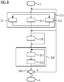
- Fig. 8 shows a method for detecting vibro-acoustic transfers in a mechanical system 5 according to a second exemplary embodiment
- Fig. 9 shows a corresponding apparatus 2 according to the second exemplary embodiment.
- the second exemplary embodiment resembles the first exemplary embodiment, and like reference numerals designate like elements. Only differences between the second exemplary embodiment and the first exemplary embodiment are described below with reference to Fig. 8 and Fig. 9 .
- the apparatus 2 according to the second exemplary embodiment also comprises a testing unit 40.
- the testing unit 40 is configured to execute step S40 of the method of the second exemplary embodiment after the plurality of contribution signals c i have been obtained according to steps S10-S30 in a manner similar to the first exemplary embodiment.
- step S40 the testing unit 40 determines a sum of the plurality of contribution signals c i . That is, the testing unit 40 determines a sum signal, wherein each reading is obtained by adding corresponding readings of each of the contribution signals c i . The testing unit 40 then proceeds to subtract the sum signal from the response signal r to obtain a result signal. The testing unit 40 calculates a root mean square value of the result signal.
- the testing unit 40 determines that the neural network device 7 is sufficiently trained. Otherwise, the testing unit 40 determines that the neural network device 7 is not sufficiently trained.
- the testing unit 40 may verify whether the contribution signals c 1 , c 2 , c 3 correctly add up to the response signal r. If the contribution signals c 1 , c 2 , c 3 do not correctly add up to the response signal r, the prediction made by the neural network device is not accurate, which may indicate the neural network device 7 is not sufficiently trained.
- the testing unit 40 When it is determined by the testing unit 40 in step S40 that the neural network device 7 is not sufficiently trained, the testing unit 40 notifies the training unit 20 that the neural network device 7 is not sufficiently trained.
- the method returns to step 20 to repeat training using the same input signals e i and the same response signal r that were previously acquired in order to perform a more intense training of the neural network device 7 using the same training input data and training output data as in a previous execution of step S20.
- the testing unit 40 when it is determined that the neural network device 7 is not sufficiently trained, the testing unit 40 returns to step S10. That is, operating of the mechanical system 5 is repeated in step S11 according to the same or a different operating pattern to acquire further operational data. After that, step S20 is repeated to perform more training of the neural network device 7 using the newly acquired operational data as training input data and training output data.
- the testing unit 40 When it is determined by the testing unit 40 in step S40 that the neural network device 7 is sufficiently trained, the testing unit 40 notifies the training unit 20 that the neural network device 7 is sufficiently trained, and the method ends E.
- step S20 when the method according to Fig. 8 is repeated in its entirety using the same mechanical system 5 and the same neural network device 7 using the same or a different operating pattern, step S20 may be obviated/ omitted, that is no training according to step S20 may be performed, when the training unit 20 has been notified that the neural network device 7 is sufficiently trained.
- Fig. 10 shows a method for detecting vibro-acoustic transfers in a mechanical system 5 according to a third exemplary embodiment
- Fig. 11 shows a corresponding apparatus 3 according to the third exemplary embodiment.
- the third exemplary embodiment resembles the first exemplary embodiment, and like reference numerals designate like elements.
- the third exemplary embodiment differs from the first exemplary embodiment in that the apparatus 3 comprises a previously trained neural network device 71 and does not comprise a training unit (20 in Fig. 2 ).
- the method shown in Fig. 10 does not comprise a training step (S20 in Fig. 2 )
- the trained neural network device 71 may be a neural network device that has been previously trained using steps such as steps S10 and S20 ( Fig. 2 ) of the method according to the first or second exemplary embodiment.
- the trained neural network device 71 may be installed in the car 5. As has been discussed for the first and second exemplary embodiment, the trained neural network device 71 may have artificial knowledge about mechanical transfers the mechanical system of the car 5. This knowledge may be used to enable various functionality of the car 5. For example, the trained neural network device 71 may be used to control an audio system, a noise cancelling system and the like of the car 5 also in unforeseen operating conditions that were not encountered during a design phase of the car 5.
- An apparatus 1, 2 for detecting vibrational and/or acoustic transfers in a prototype car 5 was built.
- the neural network device 7 of the apparatus 1, 2 was configured to implement a recurrent neural network.
- the recurrent neural network included several layers of artificial neurons, and in particular, an input layer, an output layer, and five hidden layers. More particularly, the recurrent neural network was configured as a long short-term memory.
- the neurons of the input layer and of the output layer were configured with a linear activation function.
- the neurons of the five hidden layers were configured with a sigmoid-shaped, hyperbolic tangent activation function. A dropout of 0.2 was implemented between each layer.
- a total number of neurons of the LSTM was 100.
- the prototype car was operated according to an operating pattern comprising 5 run-up operations runs, all on 4 th gear at 50 % throttle. Respective input and response signals were acquired, each comprising 27136 readings.
- the neural network device 7 was trained in batches of 1000 readings. Convergence was obtained in less than 1000 epochs.
- Contribution signals c i of individual input signals e i and a predicted response signal for the plurality of input signals e i were determined using both a method according to the embodiments and using conventional transfer path analysis (TPA).
- TPA transfer path analysis
- supervised training has been described as a method of training the neural network device 7.
- an unsupervised training method may be used instead.
- a car 5 has been described as an example of the mechanical system 5.
- the present invention may also be useful in applications in aviation engineering, machinery engineering, and the like.
- the graphical decomposition 8 shown in Fig. 7 is merely an example.
- the graphical decomposition 8 may comprise a different, such as a larger, quantity of operating ranges and a different (larger) quantity of contribution signals c i .
- Other ways of visualizing the contribution signals c i may be used for the graphical decomposition 8, such as a plurality of graphs, plots, pie charts, and the like.
- a respective neural network device is implemented to receive a plurality of input signals and to generate a plurality of output signals after being trained, wherein the output signals are generated employing artificial intelligence acquired through the before-mentioned training processes.
- the input and output signals may comprise encoded data referring to or representing physically observable quantities.
- such quantity is a mechanical or vibrational load, a frequency, or another mechanical stimulus to the mechanical system and/or a measure for an NVH contribution.
- input and or output signals are generated and transmitted through a network, and the content of the signals are stored at least temporarily by respective memory devices.
- the disclosed embodiments of methods and devices allow for an efficient transfer path analysis in car or vehicle design automation.
Landscapes
- Physics & Mathematics (AREA)
- Engineering & Computer Science (AREA)
- Theoretical Computer Science (AREA)
- General Physics & Mathematics (AREA)
- General Health & Medical Sciences (AREA)
- General Engineering & Computer Science (AREA)
- Biophysics (AREA)
- Computational Linguistics (AREA)
- Data Mining & Analysis (AREA)
- Evolutionary Computation (AREA)
- Artificial Intelligence (AREA)
- Molecular Biology (AREA)
- Computing Systems (AREA)
- Biomedical Technology (AREA)
- Life Sciences & Earth Sciences (AREA)
- Mathematical Physics (AREA)
- Software Systems (AREA)
- Health & Medical Sciences (AREA)
- Acoustics & Sound (AREA)
- Testing Of Devices, Machine Parts, Or Other Structures Thereof (AREA)
- Measurement Of Mechanical Vibrations Or Ultrasonic Waves (AREA)
Description
- The present invention relates to the field of vibrational and/or acoustic analysis of mechanical systems, and, more particularly to a method and apparatus for detecting vibrational and/or acoustic transfers in a mechanical system.
- In a mechanical system such as an automobile, sensations such as noise, vibration and harshness (NVH) may be experienced by an observer at a receiver location, such as a driver or passenger seat. In vehicle engineering, there is a need to identify excitation sources contributing to the experienced NVH. Transfer path analysis (TPA) is a known method for tracing transfers of vibro-acoustic energy from an excitation source, via a plurality of structure- and air-born transfer paths, to a receiver location. Performing TPA typically comprises acquiring mechanical loads acting on the mechanical system during an operational test; and estimating a plurality of system response functions (SRF) characterizing the plurality of transfer paths. The SRFs may be estimated in an excitation test. An excitation test may be a time-consuming procedure, which may require disassembling the vehicle body and equipping the vehicle body with force sensors at interface locations between an active and a passive component thereof.
-
EP 2 113 755 A1 -
US 2016/0343180 A1 discloses an automobile diagnostic system, wherein the method includes identifying a pattern in the electrical waveform data signal.US 2005/149234 A1 deals with analyzing engine unbalance conditions.US 5 602 761 relates to accurate machine monitoring technique based on vibration analysis.US 5 995 910 A relates to a system for training a neural network to synthesize vibration data relating to the operation of a machine. - It is one object of the present invention to provide a method and device capable of improving the detection of vibrational and/or acoustic transfers in a mechanical system.
- According to a first aspect, a method for detecting vibrational and/or acoustic transfers in a mechanical system including a plurality of mechanically interacting elements is proposed according to
claim 1. - The proposed method may favorably enable obtaining a prediction of the contributions of the mechanical loads acting on the input points to the response signal at the response point without estimating characterizing data of the mechanical system such as system transfer functions. An excitation testing may not be needed. Vibrational and/or acoustic transfers in the mechanical system may be favorably detected solely based on operational data (input signals acquired during operation). The method may favorably allow fast and cost-efficient detection of vibro-acoustic transfers in the mechanical system.
- Examples of the mechanical system including a plurality of mechanically interacting elements include a vehicle, an automobile, an airplane, a piece of machinery.
- Examples of the mechanically interacting elements include a vehicle body, a suspension, a strut tower, a tire, a motor, an engine, a cabin, a panel, a seat, a window, a hood, a door, various parts thereof, and the like.
- The plurality of mechanically interacting elements may be coupled so as to interact via a plurality of structural and/or airborne transfer paths.
- Operating the mechanical system may include operating a primary excitation source included in the mechanical system. The primary excitation source may be a motor, and engine or the like.
- In particular, in the case of a vehicle, operating the mechanical system may refer to driving the vehicle on a road and/or operating the vehicle on a test stand.
- An operating pattern may be a time sequence of operating parameters, such as power, rotations per minute, gear, and the like, to be supplied to the motor, the engine, a clutch and the like to control operation of the mechanical system.
- Operating the mechanical system may include exciting the mechanical system. In particular, one or more of the mechanically interacting elements may be excited by the primary excitation source and/or by one or more secondary excitation sources.
- A secondary excitation source may represent a source of excitations resulting from external mechanical interaction between one of the mechanically interacting elements of the mechanical system and an external element. Such external mechanical interaction may take place in response to the mechanical system being operated. An example for a secondary excitation source is a tire which externally interacts with a road (external element) in response to the vehicle being driven by the motor.
- In response to the mechanical system being excited when the mechanical system is operated according to the operating pattern, mechanical loads may act on the mechanical system.
- The mechanical loads may be acoustic and/or vibrational mechanical loads.
- The mechanical loads acting on the mechanical system may be transferred through the system along the plurality of transfer paths.
- The vibrational and/or mechanical loads may be detected at the plurality of input points and at the response point using a plurality of sensors, such as an accelerometer, a microphone, a force sensor, a pressure gauge, a strain gauge and the like.
- Preferably, each of the plurality of input points may be assigned to one of a first plurality of the mechanically interacting elements at which the mechanical system is excited during operation.
- Preferably, the response point may be assigned to one of a second plurality of the mechanically interacting elements which responds to the loads transferred along the plurality of transfer paths when the mechanical system is excited during operation.
- A respective of the input points and the response point may be assigned by placing a corresponding sensor at a respective of the mechanically interacting elements.
- When the mechanical system is a motor vehicle, examples of locations of the input points include locations at a motor bearing, at a wiper motor bracket, at a strut bearing, at an exhaust pipe bracket and the like, and examples of locations of the response point include locations at a driver seat, at a passenger seat, at a head support, and the like.
- A respective input signal and the response signal may each be a signal supplied by a respective of the sensors, such as an acceleration signal, such as an acoustic signal and/or a vibrational signal, a force signal, a pressure signal, a strain signal, and the like.
- A respective signal, such as a respective input signal and the response signal, may each be acquired as a sequence of readings. A respective reading may be a vibrational and/or acoustic frequency value, a force value, a pressure value, a strain value or the like.
- In a respective signal, a respective reading may be associated with one or more parameters. The one or more parameters may include a time. The one or more parameters may include an operating parameter of the operating pattern used during operation when the respective reading was acquired.
- In other words, a respective signal may be a signal in time domain, in rotations per minute domain, or the like.
- The neural network device may be configured to implement a neural network having machine learning ability and/or artificial intelligence. The neural network may comprise a plurality of artificial neurons. A number of artificial input neurons of the neural network may correspond to the number of input points. A number of artificial output neurons of the neural network may correspond to a number of response points.
- The number of artificial output neurons may be one or more. In particular, each input point of the mechanical system may be associated with a corresponding one of the input neurons of the neural network, and the response point of the mechanical system may be associated with the output neuron of the neural network.
- The neural network device may be configured to perform machine learning by adapting an internal structure of the neural network in response to being trained. Training may compromise repeatedly providing training input data and training output data to the neural network device.
- When trained, the neural network device may be configured to, in response to being provided with input data, provide output data based on information learned by the neural network device during training.
- Herein, machine learning ability and/or artificial intelligence may refer to the fact that the neural network device, by being trained with a number of samples of input and output data, may acquire an ability to predict output data for input data that differs from the input data used during training.
- Specifically, through training with a number of samples of the acquired plurality of input signals and the acquired response signal of the mechanical system, the neural network device may acquire an ability to predict a response signal for other pluralities of input signals (other combinations of the same input signals and/or combinations of other input signals).
- Providing a respective signal as input data or training input data to the neural network device may refer to feeding readings included in the signal one after another to a corresponding one of the input neurons of the neural network implemented by the neural network device. Herein, a respective reading may be fed to the neuron together with an associated parameter, such as an operating parameter included in the signal in association with the respective reading.
- Obtaining a signal as output data from the trained neural network device may refer to reading readings from an output neuron of the neural network implemented by the neural network device and forming a signal from the plurality of readings obtained in this way.
- Providing only the input signal acquired at one input point as input data to the trained neural network device may refer to providing the input signal to a corresponding one of the input neurons and providing no input signal, or providing a signal that is continuously zero, to any other input neurons of the neural network.
- That is, after having been trained on operational data in steps a) and b), in steps c) and d), the neural network device may be used to predict a behavior of the mechanical system when hypothetically excited by a respective plurality of input signals comprising only one input signal acquired at a respective one of the plurality of input points.
- That is, the contribution signal may be a respective predicted response signal for a respective single input signal.
- In other words, step c) and d) may be described as performing a decomposition of the plurality of input signals into respective single input signals and determining a predicted response signal corresponding to a respective single input signal.
- The proposed method has been devised under an assumption that a predicted response signal corresponding to a hypothetical excitation by a single input signal of the plurality of input signals may also be indicative of a contribution that the single input signal has to an actual response signal when the mechanical system is excited by the plurality of input signals.
- A predicted contribution of a respective input signal to the response signal may also be referred to as a portion of the input signal that is transferred into the response signal.
- Obtaining the contribution signal may therefore correspond to detecting vibrational and/or acoustic transfers in the mechanical system.
- That is, the proposed method may advantageously be able to detect vibrational and/or acoustic transfers in the mechanical system based on operational data and machine learning, without requiring the mechanical system to be disassembled to determine system characterization data, without performing an excitation test, without identifying transfer paths, estimating system transfer functions and the like.
- Thereby, vibrational and/or acoustic transfers of a prototype may be identified, and appropriate corrective measures may be taken.
- In particular, a vehicle design process may be accelerated and cost may be reduced.
- According to an embodiment, the method further comprises testing the trained neural network device by determining a sum of the plurality of contribution signals; subtracting the sum of the plurality of contribution signals from the response signal; determining that the neural network device is sufficiently trained if a result of the subtraction is less than a predetermined threshold; and otherwise, determining that the neural network device is not sufficiently trained.
- Thereby, an accuracy of the proposed method may be validated and confidence in the determined contribution signals may be advantageously increased.
- In response to determining that the neural network device is not sufficiently trained, steps b) and/or steps a) and b) may be repeated until the neural network device is determined to be sufficiently trained.
- Alternatively, in response to determining that the neural network device is not sufficiently trained, a warning message may be displayed or transmitted to an operator.
- Optionally, in response to determining that the neural network device is not sufficiently trained, at least one of the neural network implemented by the neural network device, the plurality of input points, the operating pattern and the like may be altered. Following said altering, steps a) and b) may be repeated.
- Determining a sum of the plurality of contribution signals and subtracting the sum form the response signal may include adding and subtracting corresponding individual readings included in the respective signals.
- Comparing the subtraction result (which may be a signal) to a predetermined threshold (which may be a scalar value) may refer to comparing a root-mean-square value, total energy content or the like of the subtraction result to the predetermined threshold.
- According to a further embodiment, the training in step b) is supervised training comprising: providing the training input data to the neural network device to obtain predicted output data; and adjusting weightings applied by respective neurons of the neural network device such as to reduce a deviation between the predicted output data and the training output data.
- A neural network device may be trained using one of supervised training, reinforced training and unsupervised training. However, supervised training according to the embodiment may have the advantage of being able to train the neural network device so as to gain artificial knowledge based on the acquired input signals and the acquired response signal.
- According to a variant of the further embodiment, the training in step b) may further comprise: providing the training output data to the neural network device to obtain predicted input data; and adjusting weightings applied by respective neurons of the neural network device such as to reduce a deviation between the predicted input data and the training input data.
- That is, the training of step b) may comprise a forward pass and a backward pass.
- Supervised training using a forward pass and a backward pass may advantageously increase an accuracy of and confidence in the neural network device and the results of the proposed method.
- According to a further embodiment, step b) comprises splitting the input signals and the response signal into a plurality of batches of predetermined length; and, for each of the batches, training the neural network device using respective portions of the input signals as the training input data and a respective portion of the response signal as the training output data.
- A respective batch may comprise a plurality of corresponding portions of a respective of the signal.
- The predetermined length may be shorter than a total length of a respective signal. Herein, "length" may refer to a number of readings comprised in a respective signal portion.
- Preferably, and as a non-limiting example, the length may be between 100 and 1000 readings. A length of 100 may beneficially enable fast training. A length of 1000 readings may beneficially provide more accurate results.
- By dividing the input signals and the response signals into a plurality of batches with shorter length during training, a machine learning performance of the neural network device may be advantageously increased.
- It is noted that subsequently providing all of the batches to the neural network device as training input data and training output data and performing a forward pass and a backward pass with each of the batches may also be referred to as an "epoch" of training.
- According to embodiments, the training in step b) may comprise a number of epochs.
- In other words, the training in step b) may be repeated a number of times.
- The number of times or epochs may be a predetermined number of 1 or greater. More preferably, and as a non-limiting example, the number of epochs may be 1000.
- Alternatively, the training in step b) may be repeated until an amount of change, between two subsequent epochs, of a deviation between the predicted output data and the training output data and/or an amount of change, between two subsequent epochs, of a deviation between the predicted input data and the training input data is less than a predetermined threshold.
- That is, training may be repeated until respective deviations converge. Thereby, the neural network device may be trained more reliably.
- According to a further embodiment, the method further comprises, while operating the mechanical system according to a second operating pattern different from the first operating pattern, acquiring, at each of the plurality of input points, a second input signal, and acquiring, at the response point of the mechanical system, a second response signal; and performing steps c) and d) using the second input signals as the input signals and the second response signal as the response signal.
- Thereby, an artificial intelligence and/or machine learning capability of the neural network device may be beneficially leveraged to detect acoustic and/or vibrational transfers in the mechanical system also when operated in a manner that was not covered by the operating pattern used during training of the neural network device.
- That is, during evaluation of the mechanical system, initially, when acquiring operational data (input signals and response signal), the neural network device may be trained using the acquired operational data and may then be used to provide the respective predicted contributions of the input signals of the same operational data that has been used during training.
- Once the neural network device has been trained, further operational data may be acquired and the neural network device may be used to provide the respective predicted contributions of the input signals of the further operational data. Therein, further training according to step b) may not be necessary and may be omitted.
- According to a second aspect, there is proposed a method for detecting vibrational and/or acoustic transfers in a mechanical system according to claim 6.
- Whereas the first aspect relates to method of training and using a neural network device, the second aspect relates to using a previously trained neural network device to obtain the respective contribution signals.
- The embodiments and features described with reference to the method of the first aspect apply mutatis mutandis to the method of the second aspect.
- According to an embodiment of the first or second aspect, the method further comprises generating and displaying a decomposition of the response signal into the predicted contributions of the input signals acquired at each of the plurality of input points.
- The displayed decomposition may be a graphical representation of each of the contribution signals. By looking at the displayed decomposition, an engineer may easily identify a large contribution among the plurality of contributions. therefrom, the engineer may understand which of the input points primarily contribute to the response signal. The engineer may use this information to undertake countermeasures to reduce the response signal and improve NVH properties of the mechanical system.
- According to a further embodiment of the first or second aspect, the method further comprises comparing the predicted contributions of the input signals acquired at each of the plurality of input points; identifying an input signal the predicted contribution of which is greatest among the plurality of predicted contributions; and altering the mechanical system at the input point at which the identified input signal has been acquired.
- Altering the mechanical system at the input point may for example comprise increasing a stiffness of one or more of the mechanically interacting elements at the input point, arranging a damping element near the input point, arranging a noise- and/or vibration cancelling source near the response point and/or altering a design of the mechanical system.
- The proposed method may advantageously be used as a design aid in a design process of a mechanical system such as an automobile.
- According to a further embodiment of the first or second aspect, the neural network device is configured to implement a recurrent neural network comprising an input layer, an output layer and at least one hidden layer, each layer comprising at least one neuron.
- A respective neuron may be configured to receive one or more inputs; apply a weighting to a respective input, determine a sum of the weighted inputs, apply a transfer function to the sum of the weighted inputs; and provide a result of applying the transfer function to the sum of the weighted inputs as an output.
- A recurrent neural network may be an artificial neural network wherein connections between neurons form a cyclic or acyclic directed graph along a sequence.
- A recurrent neural network may favorably include an internal state or memory, enabling it to process sequences of input data such as an input signal including a plurality of readings.
- The input layer may comprise a plurality of input neurons, wherein each input neuron is associated with a respected input point according to the proposed method.
- The output layer may comprise an output neuron associated with the response point according to the proposed method.
- A respective hidden layer may comprise internal neurons that may increase a machine learning capability and/or artificial engine of the recurrent neural network.
- There is at least one hidden layer. More preferably, a number of hidden layers may be five.
- According to a further embodiment, the neurons of the input layer and the output layer are each configured with a linear activation function and the neurons of the at least one hidden layer are each configured with a sigmoid-shaped activation function.
- Specifically, the sigmoid-shaped function may be a hyperbolic tangent function.
- According to a further embodiment, the recurrent neural network is a long short-term memory.
- A long short-term memory, or LSTM, may be a recurrent neural network comprising a plurality of LSTM units. Each LSTM unit may comprise, as artificial neurons, a cell, an input gate, an output gate and a forget gate.
- Implementing a LSTM may beneficially improve the ability of the neural network device to learn and predict complex behaviors of the mechanical system.
- According to a further embodiment, a total number of neurons of the recurrent neural network is between 10 and 250.
- More preferably, and as a non-limiting example, the number of neurons may be 100.
- Any embodiment of the first or second aspect may be combined with any embodiment of the first or second aspect to obtain another embodiment of the first or second aspect.
- According to a third aspect, the invention relates to a computer program product according to claim 15.
- A computer program product, such as a computer program means, may be embodied as a memory card, USB stick, CD-ROM, DVD or as a file which may be downloaded from a server in a network. For example, such a file may be provided by transferring the file comprising the computer program product from a wireless communication network.
- According to a fourth aspect, an apparatus for detecting vibrational and/or acoustic transfers in a mechanical system including a plurality of mechanically interacting elements is proposed according to claim 13.
- The embodiments and features described with reference to the method according to the first aspect apply mutatis mutandis to the apparatus of the fourth aspect.
- According to a fifth aspect, an apparatus for detecting vibrational and/or acoustic transfers in a mechanical system including a plurality of mechanically interacting elements is proposed according to claim 14.
- The embodiments and features described with reference to the method according to the second aspect apply mutatis mutandis to the apparatus of the fifth aspect.
- A respective entity, such as the neural network device, the acquisition unit, the training unit and/or the prediction unit may be implemented in hardware and/or in software. If said entity is implemented in hardware, it may be embodied as a device, e.g. as a computer or as a processor or as a part of a system, e.g. a computer system. If said entity is implemented in software, it may be embodied as a computer program product, as a function, as a routine, as a program code or as an executable object.
- Further embodiments, features and advantages of the present invention will become apparent from the subsequent description and dependent claims, taken in conjunction with the accompanying drawings, in which:
-
Fig. 1 shows a method for detecting vibro-acoustic transfers in a mechanical system according to a first exemplary embodiment. -
Fig. 2 shows an apparatus for detecting vibro-acoustic transfers in a mechanical system according to the first exemplary embodiment. -
Fig. 3 is a block diagram illustrating conceptual details of step S20 ofFig. 1 . -
Fig. 4, 5 , and6 are block diagrams illustrating conceptual details of step S30 ofFig. 1 . -
Fig. 7 shows a graphical decomposition of the response signal into a plurality of contribution signals according to a preferred development of the first exemplary embodiment. -
Fig. 8 shows a method for detecting vibro-acoustic transfers in a mechanical system according to a second exemplary embodiment. -
Fig. 9 shows an apparatus for detecting vibro-acoustic transfers in a mechanical system according to the second exemplary embodiment. -
Fig. 10 shows a method for detecting vibro-acoustic transfers in a mechanical system according to a third exemplary embodiment. -
Fig. 11 shows an apparatus for detecting vibro-acoustic transfers in a mechanical system according to the third exemplary embodiment. - In the Figures, like reference numerals designate like or functionally equivalent elements, unless otherwise indicated.
- First, an example of a mechanical system comprising a plurality of interacting mechanical elements will be briefly described with reference to
Fig. 2 . -
Fig. 2 shows, inter alia, a prototype car 5 ("car" hereinbelow) as one possible example of the mechanical system. In particular, thecar 5 comprises a plurality of mechanically interacting elements, such as, for example, amotor 51, afront wheel 52, arear wheel 53, aback door 54 and aseat 55. - When the
car 5 is driven on a road or a test stand (not shown), acoustic and/or vibrational mechanical loads may act upon themechanical system 5 at a plurality of excitation sources. Specifically, vibrations of the motor 51 (primary excitation source), vibrations caused by rotation of thewheels wheels back door 54 and the like (secondary excitation sources), may be input to themechanical system 5. - These acoustic and/or vibrational mechanical loads input to the
mechanical system 5 may be transferred through thecar 5 along a variety of structural and/or air-borne transfer paths and may ultimately reach a passenger sitting in theseat 55. The passenger may experience an unpleasant noise, vibrational or harshness (NVH) sensation. - During design of the
prototype car 5, it may be desirable to know to which amount each of theexcitation sources -
Fig. 1 shows a method for detecting vibro-acoustic transfers in themechanical system 5 shown inFig. 2 according to a first exemplary embodiment. InFig. 1 , rectangles denote method steps and arrows denote a sequence of execution of the method steps. -
Fig. 2 shows, next to thecar 5, anapparatus 1 for detecting vibro-acoustic transfers in themechanical system 5 according to the first exemplary embodiment. InFig. 2 , rectangles illustrate respective entities, units devices and/or apparatuses, and arrows illustrate a signal flow. - The first exemplary embodiment will be described with reference to both
Fig. 1 and Fig. 2 . - The
apparatus 1 ofFig. 2 comprises anacquisition unit 10, atraining unit 20, aprediction unit 30 and aneural network device 7. - As the method starts (S), in step S10 of the method illustrated in
Fig. 1 , operational data is acquired from thecar 5. - More specifically, in step S11, the
car 5 is operated according to an operating pattern. According to one variant, thecar 5 may be driven on a road (not shown) and an operating parameter, such as a rpm value (rotations per minute) of themotor 51, may be recorded in predetermined time intervals and stored in association with time as the operating pattern. According to another variant, thecar 5 may be operated on a test stand (not shown) according to a predetermined operating pattern. - While the
car 5 is being operated in this manner, in step S12, theacquisition unit 10 of theapparatus 1 acquires a plurality of input signals ei from a plurality of input points 61-64 located in thecar 5. - Herein, each of the input points 61-64 may be located at or near a respective one of the
primary excitation source 51 and the plurality of secondary excitation sources 52-54. A respective input signal ei is a signal indicative of a mechanical load acting on themechanical system 5 at the respective input point (one of 61-64). - A respective input signal ei may be a force signal, an acceleration signal, an acoustic or vibrational signal, a noise signal, a strain signal and may be acquired using a force sensor, an accelerometer, a microphone, a strain gauge or the like (not shown) placed at a respective input point (one of 61-64).
- At the same time, while the
car 5 is being operated according to step S11 and the input signals ei are acquired according to step S12, theacquisition unit 10 also acquires a response signal r from aresponse point 65 located in thecar 5. - Specifically, the response point may be located at or near a location where a passenger experiences an unpleasant NVH sensation, such as at a head rest of the
seat 55. - Also, the response signal r may be a force signal, an acceleration signal, an acoustic or vibrational signal, a noise signal, a strain signal and may be acquired using a force sensor, an accelerometer, a microphone, a strain gauge or the like placed at the
response point 65. - The
acquisition unit 10 provides the plurality of input signals ei and the response signal r to thetraining unit 20. - In step S20 of the method illustrated in
Fig. 1 , thetraining unit 20 trains theneural network device 7 using the acquired operational data of themechanical system 5 so as to cause theneural network device 7 to learn the behavior of themechanical system 5. - More specifically, the training unit S20 provides the plurality of input signals ei as training input data to the
neural network device 7 and also provides the response signal r as training output data to theneural network device 7, to train theneural network device 7. - The
training unit 20 provides the plurality of input signals ei and the response signal r to theprediction unit 30. - In step S30, the
prediction unit 30 uses theneural network device 7 to obtain a plurality of contribution signals ci indicative of a predicted contribution of the input signal ei acquired at the respective of the input points 61-64 to the response signal r acquired at theresponse point 65. - More specifically, steps S31 and S32 are executed once for each of the plurality of input points 61-64.
- In step S31, the
prediction unit 30 provides only the input signal ei acquired at the respective input point (one of 61-64) as input data to the trainedneural network device 7. - In response to providing only the input signal ei acquired at the respective input point (one of 61-64) to the trained
neural network device 7 in step S31, the prediction unit obtains, in step S32, output data from the trainedneural network device 7. From the output data obtained in this way, theprediction unit 30 forms a contribution signal ci. - A respective contribution signal ci obtained in this way is considered to be indicative of a predicted contribution of a respective input signal ei to the response signal r. A predicted contribution of a respective input signal ei to the response signal r may also be referred to as a portion or amount of the respective input signal ei that is transferred through the
mechanical system 5 and becomes part of the response signal r at theresponse point 65. - The plurality of contribution signals ci is provided as an output of the method of
Fig. 1 and theapparatus 1 ofFig. 2 , and the method ends (E). - Conceptual details of preferred further developments of the first exemplary embodiment will now be described with reference to
Fig. 3-6 . -
Fig. 3 is a block diagram illustrating conceptual details of step S20 ofFig. 1 . andFig. 4 ,5 , and6 are block diagrams illustrating conceptual details of step S30 ofFig. 1 . - Specifically, in step S20 (
Fig. 1 ), as is shown in the block diagram inFig. 3 , theneural network device 7 is trained using the plurality of acquired input signals e1, e2, ..., en, as training input data and using the acquired response signal r as training output data. - The training may be carried out as supervised training comprising a forward pass and a reverse pass, as illustrated by the bijective arrows in
Fig. 3 . - Specifically, each of input signals e1, e2, ... en and the response signal r may be split into a plurality of corresponding portions of predetermined length. The predetermined length may be between 100 and 1000 readings. A respective set comprising a corresponding portion of the predetermined length of each of the input signals e1, e2, ... en and the response signal may also be referred to as a batch.
- During a forward pass of the supervised training, for each of the batches, the corresponding portions of each of the input signals e1, e2, ... en are provided to the
neural network device 7 as training input data, and output data obtained from theneural network device 7 in response to the training input data is compared to the corresponding portion of the response signal of the batch. Weightings applied by respective neurons of theneural network device 7 are adjusted so as to reduce a deviation between the output data obtained from theneural network device 7 and the corresponding portion of the response signal r of the batch. - During a backward pass of the supervised training, for each of the batches, the corresponding portion of the response signal r is provided to the
neural network device 7 as training output data, theneural network device 7 is operated in a reverse manner, and training input data obtained from theneural network device 7 in response to the training output data is compared to the corresponding portions of the input signals e1, e2, ... en of the batch. Weightings applied by the respective neurons of theneural network device 7 are adjusted so as to reduce a deviation between the input data obtained from theneural network device 7 and the corresponding portions of the input signals e1, e2, ... en of the batch. - After a forward pass and a backward pass have been completed for each of the batches, one epoch of training is completed.
- It is noted herein that a respective signal e1, e2, ... en, r may include a number of readings, and that each reading may be associated with an operating parameter used at the time of acquisition of the respective reading for operating the
mechanical system 5 according to the operating pattern in step S11. - Along with each reading, a respective associated operating parameter may be provided to the
neural network device 7 as part of the training input data and/or the training input data. Thereby, theneural network device 7 may learn the behavior of themechanical system 5 under different operating conditions defined by said operating parameters. - Step S20 may proceed to repeat the training steps described above to complete a predetermined number of epochs and/or until convergence of respective deviations between the training output data and the response signal r (forward pass) and between the training input data and the plurality of input signals e1, e2, ... en is attained.
- In this manner, a trained
neural network device 7 may be obtained. - Specifically, in step S30 (
Fig. 1 ), steps S31 and S31 are repeated for each of the plurality of input points, i.e., for each of the plurality of input signals e1, e2, ... en - Specifically, in a first iteration in the loop of S30 shown in
Fig. 1 , only the input signal e1 is provided to the trainedneural network device 7 in step S31 (Fig. 1 ), as is shown inFig. 4 . Input signals e2, ..., en are not provided to the trainedneural network device 7. From the output data obtained from the trainedneural network device 7 in response to the input signal e1 in step S32 (Fig. 1 ), a contribution signal c1 is formed. The contribution signal c1 is considered to be a prediction of a contribution of the input signal e1 acquired at a corresponding input point (61 inFig. 2 ) to the response signal r acquired at the response point (65 inFig. 2 ) . - Next, as is shown in
Fig. 5 , only the input signal e2 is provided to the trainedneural network device 7. From the output data obtained from the trainedneural network device 7 in response to the input signal e2, a contribution signal c2 indicative of a predicted contribution of the input signal e2 to the response signal r is formed. - Steps S31 and S32 (
Fig. 1 ) are repeated in this manner for each of the input signals ei. - Finally, as is shown in
Fig. 6 , only the input signal en is provided to the trainedneural network device 7. From the output data obtained from the trainedneural network device 7 in response to the input signal en, a contribution signal cn indicative of a predicted contribution of the input signal en to the response signal r is formed. - Merely in order to facilitate understanding, step S30 (
Fig. 2 ) may also be described in the following way, wherein reference is made toFigs. 2 to 6 :
The trainedneural network device 7 may be used to predict, for each of the input points 61-64, a behavior of themechanical system 5 in a hypothetical situation in which a mechanical load is acting only on a respective single input point (one of 61-64). Herein, the output data provided by the neural network device in each ofFig. 4 to Fig. 6 may be considered to be a respective predicted hypothetical response signal predicted to be generated in themechanical system 5 at theresponse point 65 when themechanical system 5 is hypothetically excited only by the respective single input signal e1, e2, ..., en at the respective single input point (one of 61-64) . - By using the
neural network device 7 in this manner to predict the behavior of themechanical system 5 in a hypothetical situation in which a mechanical load is acting only on a respective single one of the input points 61-64, transfers of mechanical loads in themechanical system 5 may be favorably detected without taking recourse to conventional transfer path analysis (TPA). - Disadvantages of TPA such as complex calculations and having to partly disassemble the mechanical system 6 to be able to carry out an excitation test may be advantageously overcome.
-
Fig. 7 shows an exemplarygraphical decomposition 8 of the response signal r into a plurality of contribution signals c1, c2, c3 according to a preferred development of the first exemplary embodiment. - The preferred development will be described with reference to
Fig. 7 andFig. 2 . - According to the preferred development, the
apparatus 1 may be configured to generate a digital representation of a graphical decomposition from the response signal r and the plurality of contribution signals c1, c2, c3. Theapparatus 1 may comprise and/or be connected to a display device (not shown). In response to being supplied with the digital representation, the display device (not shown) may display a digital representation similar to the exemplarydigital representation 8 shown inFig. 7 . - In the exemplary
graphical decomposition 8 shown inFig. 7 , an operation parameter such as a number of rotations per minute is plotted on the horizontal axis. Respective signals r, c1, c2, c3 are shown on top of each other along the vertical axis. An empty rectangle denotes low vibro-acoustic load (db0) of a respective signal in a respective operating parameter range. A hatched rectangle denotes medium vibro-acoustic load (db1). A cross-hatched rectangle denotes high vibro-acoustic load (db2). A triple-hatched rectangle denotes very high vibro-acoustic load (db3). The vibro-acoustic load may be in units of decibels in one example. - As can be seen in
Fig. 7 , the response signal r acquired at theresponse point 65 indicates high or very high vibro-acoustic load over a wide operating parameter range from 0 to 3000 rpm. A counter-measure to improve an NVH experience at theresponse point 65 is needed. - As also shown in
Fig. 7 , the contribution signals c1, c2 and c3 constitute a decomposition of the response signal r. That is, a respective portion of the response signal r may be represented as a sum of corresponding (same position along the horizontal axis) portions of the contribution signals c1, c2, c3. - The
exemplary decomposition 8 includes information that, according to the prediction made by theneural network device 7, a highest contribution to the response signal r in the operating parameter range from 0 to 1000 rpm is the contribution c1 of an input signal e1 acquired at a first input point (such as near thefirst input point 61 at the motor 51). Accordingly, a countermeasure may be taken in the operating parameter range from 0 to 1000 rpm at thefirst input point 61. - The
exemplary decomposition 8 further includes information that the contribution c3 of an input signal e3 acquired at a third input point 63 (such as the rear axis next to the rear wheel 53), to the response signal r is high in the operating parameter range from 2000 to 3000 rpm. Accordingly, a countermeasure may be taken in the operating parameter range from 2000 to 3000 rpm at thethird input point 63. - A respective countermeasure may comprise altering the
mechanical system 5 at the respective input point (one of 61-64). For example, a stiffness may be increased in an area of theinput point mechanical system 5 may be altered to alter a location of therespective input point respective input point response point 65. - The respective countermeasure may be taken manually by an engineer or automatically, based on the contribution signals ci output by the
apparatus 1, by a design assistance device (not shown). - According to a further preferred development, the
apparatus 1 may output the contribution signals ci to a design assistance device or the like so as to cause altering themechanical system 5 without generating thegraphical decomposition 8. -
Fig. 8 shows a method for detecting vibro-acoustic transfers in amechanical system 5 according to a second exemplary embodiment, andFig. 9 shows acorresponding apparatus 2 according to the second exemplary embodiment. - The second exemplary embodiment resembles the first exemplary embodiment, and like reference numerals designate like elements. Only differences between the second exemplary embodiment and the first exemplary embodiment are described below with reference to
Fig. 8 andFig. 9 . - The
apparatus 2 according to the second exemplary embodiment also comprises atesting unit 40. Thetesting unit 40 is configured to execute step S40 of the method of the second exemplary embodiment after the plurality of contribution signals ci have been obtained according to steps S10-S30 in a manner similar to the first exemplary embodiment. - In step S40, the
testing unit 40 determines a sum of the plurality of contribution signals ci. That is, thetesting unit 40 determines a sum signal, wherein each reading is obtained by adding corresponding readings of each of the contribution signals ci. Thetesting unit 40 then proceeds to subtract the sum signal from the response signal r to obtain a result signal. Thetesting unit 40 calculates a root mean square value of the result signal. - If the root mean square value if below a predetermined threshold, the
testing unit 40 determines that theneural network device 7 is sufficiently trained. Otherwise, thetesting unit 40 determines that theneural network device 7 is not sufficiently trained. - In other words, and merely to facilitate understanding, with reference to
Fig. 7 , thetesting unit 40 may verify whether the contribution signals c1, c2, c3 correctly add up to the response signal r. If the contribution signals c1, c2, c3 do not correctly add up to the response signal r, the prediction made by the neural network device is not accurate, which may indicate theneural network device 7 is not sufficiently trained. - When it is determined by the
testing unit 40 in step S40 that theneural network device 7 is not sufficiently trained, thetesting unit 40 notifies thetraining unit 20 that theneural network device 7 is not sufficiently trained. - After that, according to one variant, the method returns to step 20 to repeat training using the same input signals ei and the same response signal r that were previously acquired in order to perform a more intense training of the
neural network device 7 using the same training input data and training output data as in a previous execution of step S20. - According to another variant, when it is determined that the
neural network device 7 is not sufficiently trained, thetesting unit 40 returns to step S10. That is, operating of themechanical system 5 is repeated in step S11 according to the same or a different operating pattern to acquire further operational data. After that, step S20 is repeated to perform more training of theneural network device 7 using the newly acquired operational data as training input data and training output data. - When it is determined by the
testing unit 40 in step S40 that theneural network device 7 is sufficiently trained, thetesting unit 40 notifies thetraining unit 20 that theneural network device 7 is sufficiently trained, and the method ends E. - According to the present exemplary embodiment, when the method according to
Fig. 8 is repeated in its entirety using the samemechanical system 5 and the sameneural network device 7 using the same or a different operating pattern, step S20 may be obviated/ omitted, that is no training according to step S20 may be performed, when thetraining unit 20 has been notified that theneural network device 7 is sufficiently trained. - It is noted that, when further operational data (such as a second plurality of input signals ei and a second response signal r) is acquired while operating the
car 5 using a second operating pattern that differs from the operating pattern used while training theneural network device 7, operating conditions may be experienced that were not experienced during the previous training step S20. Nevertheless, theneural network device 7 may advantageously be able to obtain contribution signals ci indicative of a predicted contribution of the respective of the second plurality of input signals ei during the operation condition that was not experienced during training, and advantageously without requiring further training. -
Fig. 10 shows a method for detecting vibro-acoustic transfers in amechanical system 5 according to a third exemplary embodiment, andFig. 11 shows acorresponding apparatus 3 according to the third exemplary embodiment. - The third exemplary embodiment resembles the first exemplary embodiment, and like reference numerals designate like elements.
- With reference to
Fig. 10 andFig. 11 , the third exemplary embodiment differs from the first exemplary embodiment in that theapparatus 3 comprises a previously trainedneural network device 71 and does not comprise a training unit (20 inFig. 2 ). Correspondingly, the method shown inFig. 10 does not comprise a training step (S20 inFig. 2 ) - The trained
neural network device 71 may be a neural network device that has been previously trained using steps such as steps S10 and S20 (Fig. 2 ) of the method according to the first or second exemplary embodiment. - The trained
neural network device 71 may be installed in thecar 5. As has been discussed for the first and second exemplary embodiment, the trainedneural network device 71 may have artificial knowledge about mechanical transfers the mechanical system of thecar 5. This knowledge may be used to enable various functionality of thecar 5. For example, the trainedneural network device 71 may be used to control an audio system, a noise cancelling system and the like of thecar 5 also in unforeseen operating conditions that were not encountered during a design phase of thecar 5. - A practical exemplary use case of the exemplary embodiments will be briefly discussed.
- An
apparatus prototype car 5 was built. - The
neural network device 7 of theapparatus - The prototype car was operated according to an operating pattern comprising 5 run-up operations runs, all on 4th gear at 50 % throttle. Respective input and response signals were acquired, each comprising 27136 readings.
- The
neural network device 7 was trained in batches of 1000 readings. Convergence was obtained in less than 1000 epochs. - Contribution signals ci of individual input signals ei and a predicted response signal for the plurality of input signals ei were determined using both a method according to the embodiments and using conventional transfer path analysis (TPA).
- A useful level of agreement between the two approaches was confirmed.
- Although the present invention has been described in accordance with preferred exemplary embodiments, it is obvious for the person skilled in the art that modifications are possible in all exemplary embodiments.
- In the exemplary embodiments, supervised training has been described as a method of training the
neural network device 7. However, an unsupervised training method may be used instead. - A
car 5 has been described as an example of themechanical system 5. However, the present invention may also be useful in applications in aviation engineering, machinery engineering, and the like. - The
graphical decomposition 8 shown inFig. 7 is merely an example. Thegraphical decomposition 8 may comprise a different, such as a larger, quantity of operating ranges and a different (larger) quantity of contribution signals ci. Other ways of visualizing the contribution signals ci may be used for thegraphical decomposition 8, such as a plurality of graphs, plots, pie charts, and the like. - It is understood that a respective neural network device is implemented to receive a plurality of input signals and to generate a plurality of output signals after being trained, wherein the output signals are generated employing artificial intelligence acquired through the before-mentioned training processes. The input and output signals may comprise encoded data referring to or representing physically observable quantities. In embodiments, such quantity is a mechanical or vibrational load, a frequency, or another mechanical stimulus to the mechanical system and/or a measure for an NVH contribution. In embodiments, input and or output signals are generated and transmitted through a network, and the content of the signals are stored at least temporarily by respective memory devices.
- The disclosed embodiments of methods and devices allow for an efficient transfer path analysis in car or vehicle design automation.
Claims (15)
- A method for detecting vibrational and/or acoustic transfers in a mechanical system (5) including a plurality of mechanically interacting elements (51-55), the method comprising:a) (S10) while operating (S11) the mechanical system (5) according to an operating pattern, acquiring (S12), at each of a plurality of input points (61-64) of the mechanical system (5), an input signal (ei) indicative of a mechanical load acting on the input point (one of 61-64) during operation, and acquiring (S13), at a response point (65) of the mechanical system (5), a response signal (r) indicative of a mechanical response of the mechanical system (5) at the response point (65);b) training (S20) a neural network device (7) using the input signals (ei) acquired at the plurality of input points (61-64) as training input data and using the response signal (r) acquired at the response point (65) as training output data; and(S30) for each of the plurality of input points (61-64):c) providing (S31) only the input signal (ei) acquired at the respective input point (one of 61-64) as input data to the trained neural network device (7); andd) obtaining (S32), as output data from the trained neural network device (7) in response to only the input signal (ei) acquired at the respective input point (one of 61-64) being provided thereto, a contribution signal (ci) indicative of a predicted contribution of the input signal (ei) acquired at the respective input point (one of 61-64) to the response signal (r) acquired at the response point (65).
- The method of claim 1,
wherein the method further comprises testing (S40) the trained neural network device (7) by- determining a sum of the plurality of contribution signals (ci);- subtracting the sum of the plurality of contribution signals (ci) from the response signal (r);- determining that the neural network device (7) is sufficiently trained if a result of the subtraction is less than a predetermined threshold; and- otherwise, determining that the neural network device (7) is not sufficiently trained. - The method of claim 1 or 2,
wherein said training in step b) is supervised training comprising:- providing the training input data to the neural network device (7) to obtain predicted output data; and- adjusting weightings applied by respective neurons of the neural network device (7) such as to reduce a deviation between the predicted output data and the training output data. - The method of any of claim 1-3,
wherein step b) comprises- splitting the input signals (ei) and the response signal (r) into a plurality of batches of predetermined length; and,
for each of the batches,- training the neural network device (7) using respective portions of the input signals (ei) as the training input data and a respective portion of the response signal (r) as the training output data. - The method of any of claim 1-4,
wherein the method further comprises,- while operating the mechanical system according to a second operating pattern different from the first operating pattern, acquiring, at each of the plurality of input points (61-64), a second input signal, and acquiring, at the response point (65) of the mechanical system, a second response signal; and- performing steps c) and d) (31, 32) using the second input signals as the input signals (ei) and the second response signal as the response signal (ri). - A method for detecting vibrational and/or acoustic transfers in a mechanical system (5) including a plurality of mechanically interacting elements (51-55) using a trained neural network device (7) trained to perform detection of vibrational and/or acoustic transfers in the mechanical system (5),
the method comprising:a') (S10) while operating (S11) the mechanical system (5) according to an operating pattern, acquiring (S12), at each of a plurality of input points (61-64) of the mechanical system (5), an input signal (ei) indicative of a mechanical load acting on the respective input point (one of 61-64) during operation, and acquiring (S13), at a response point of the mechanical system, a response signal (r) indicative of a mechanical response of the mechanical system (5) at the response point (65);(S30) for each of the plurality of input points (61-64):c) providing (S31) only the input signal (ei) acquired at the respective input point (61-64) as input data to the trained neural network device (7); andd) obtaining (S32), as output data from the trained neural network device (7) in response to only the input signal (ei) acquired at the respective input point (one of 61-64) being provided thereto, a contribution signal (ci) indicative of a predicted contribution of the input signal (ei) acquired at the input point (61-64) to the response signal (r) acquired at the response point (65),wherein training (S20) of the neural network device (7) is using the input signals (ei) acquired at the plurality of input points (61-64) as training input data and using the response signal (r) acquired at the response point (65) as training output data; and (S30) for each of the plurality of input points (61-64). - The method of any of claim 1-6,
wherein the method further comprises generating and displaying a decomposition (8) of the response signal (r) into the predicted contributions of the input signals (ei) acquired at each of the plurality of input points. - The method of any of claim 1-7,
wherein the method further comprises comparing the predicted contributions of the input signals (ei) acquired at each of the plurality of input points (61-64); identifying an input signal (ei) the predicted contribution of which is greatest among the plurality of predicted contributions; and altering the mechanical system (5) at the input point (61-64) at which the identified input signal (ei) has been acquired. - The method of any of claim 1-8,
wherein the neural network device (7) is configured to implement a recurrent neural network comprising an input layer, an output layer and at least one hidden layer, each layer comprising at least one neuron. - The method of claim 9,
wherein the neurons of the input layer and the output layer are each configured with a linear activation function and the neurons of the at least one hidden layer are each configured with a sigmoid-shaped activation function. - The method of claim 9 or 10,
wherein the recurrent neural network is a long short-term memory. - The method of any of claim 9-11,
wherein a total number of neurons of the recurrent neural network is between 10 and 250. - An apparatus (1, 2) for detecting vibrational and/or acoustic transfers in a mechanical system (5) including a plurality of mechanically interacting elements (51-55), the apparatus (1, 2) comprising a neural network device (7) and further comprising:an acquisition unit (10) configured to a) while the mechanical system (5) is operated according to an operating pattern, acquire, at each of a plurality of input points (61-64) of the mechanical system (5), an input signal (ei) indicative of a mechanical load acting on the input point (61-64) during operation, and acquire, at a response point (65) of the mechanical system (5), a response signal (r) indicative of a mechanical response of the mechanical system (5) at the response point (65);a training unit (20) configured to b) train the neural network device (7) using the input signals (ei) acquired at the plurality of input points (61-64) as training input data and using the response signal (r) acquired at the response point (65) as training output data; anda prediction unit (30) configured to, for each of the plurality of input points (61-64):c) provide only the input signal (ei) acquired at the respective input point (61-64) as input data to the trained neural network device (7); andd) obtain, as output data from the trained neural network device (7) in response to only the input signal (ei) acquired at the respective input point (61-64) being provided thereto, a contribution signal (ci) indicative of a predicted contribution of the input signal (ei) acquired at the respective input point (61-64) to the response signal (r) acquired at the response point (65).
- An apparatus (3) for detecting vibrational and/or acoustic transfers in a mechanical system (5) including a plurality of mechanically interacting elements (51-55), the apparatus (3) comprising a trained neural network device (7) which is trained to perform detection of vibrational and/or acoustic transfers in the mechanical system (5), and further comprising:an acquisition unit (10) configured to a') while the mechanical system (5) is operated according to an operating pattern, acquire, at each of a plurality of input points (61-64) of the mechanical system (5), an input signal indicative of a mechanical load acting on the input point (61-64) during operation, and acquire, at a response point (65) of the mechanical system (5), a response signal (r) indicative of a mechanical response of the mechanical system (5) at the response point (65);a prediction unit (30) configured to, for each of the plurality of input points (61-64):c) provide only the input signal (ei) acquired at the respective input point (61-64) as input data to the trained neural network device (7); andd) obtain, as output data from the trained neural network device (7) in response to only the input signal (ei) acquired at the respective input point (61-64) being provided thereto, a contribution signal (ci) indicative of a predicted contribution of the input signal (ei) acquired at the respective input point (61-64) to the response signal (r) acquired at the response point (65),wherein training (S20) of the neural network device (7) is using the input signals (ei) acquired at the plurality of input points (61-64) as training input data and using the response signal (r) acquired at the response point (65) as training output data; and (S30) for each of the plurality of input points (61-64).
- A computer program product comprising a program code for executing the method of any of claims 1-12 when run on an apparatus according to claim 13 or 14,the apparatus including at least one computer,wherein the neural network device, the acquisition unit, the training unit and the prediction unit are implemented in software to be executed as said computer program product.
Applications Claiming Priority (1)
| Application Number | Priority Date | Filing Date | Title |
|---|---|---|---|
| PCT/EP2018/064236 WO2019228625A1 (en) | 2018-05-30 | 2018-05-30 | Method and apparatus for detecting vibrational and/or acoustic transfers in a mechanical system |
Publications (2)
| Publication Number | Publication Date |
|---|---|
| EP3775801A1 EP3775801A1 (en) | 2021-02-17 |
| EP3775801B1 true EP3775801B1 (en) | 2022-04-20 |
Family
ID=62567627
Family Applications (1)
| Application Number | Title | Priority Date | Filing Date |
|---|---|---|---|
| EP18730283.1A Active EP3775801B1 (en) | 2018-05-30 | 2018-05-30 | Method and apparatus for detecting vibrational and/or acoustic transfers in a mechanical system |
Country Status (4)
| Country | Link |
|---|---|
| US (1) | US11187619B2 (en) |
| EP (1) | EP3775801B1 (en) |
| CN (1) | CN112204362B (en) |
| WO (1) | WO2019228625A1 (en) |
Families Citing this family (11)
| Publication number | Priority date | Publication date | Assignee | Title |
|---|---|---|---|---|
| US10985951B2 (en) * | 2019-03-15 | 2021-04-20 | The Research Foundation for the State University | Integrating Volterra series model and deep neural networks to equalize nonlinear power amplifiers |
| WO2021013331A1 (en) * | 2019-07-22 | 2021-01-28 | Siemens Industry Software Nv | Method and apparatus for estimating electromagnetic forces active in an electric machine |
| KR20210152206A (en) * | 2020-06-08 | 2021-12-15 | 현대자동차주식회사 | Method and apparatus for predicting the performance of a vehicle nvh system based on deep learning |
| DE102020213899A1 (en) | 2020-11-04 | 2022-05-05 | Fraunhofer-Gesellschaft zur Förderung der angewandten Forschung eingetragener Verein | SENSOR SYSTEM |
| JP7392633B2 (en) * | 2020-11-10 | 2023-12-06 | トヨタ自動車株式会社 | Vehicle noise inspection device |
| CN115248077B (en) * | 2021-04-28 | 2024-09-20 | 上海沃尔沃汽车研发有限公司 | Method and system for evaluating road noise of in-vehicle structure |
| CN113465733B (en) * | 2021-08-13 | 2022-04-05 | 重庆大学 | Method and device for predicting displacement response of shaking table structure based on EEMD-DNN |
| CN113465732B (en) * | 2021-08-13 | 2022-04-05 | 重庆大学 | Method and device for predicting displacement response of shaking table structure based on EMD-DNN |
| CN113963676B (en) * | 2021-10-20 | 2022-06-03 | 深圳技术大学 | Noise control method for passenger car |
| US20240110825A1 (en) * | 2022-09-30 | 2024-04-04 | Robert Bosch Gmbh | System and method for a model for prediction of sound perception using accelerometer data |
| CN116415339A (en) * | 2023-06-06 | 2023-07-11 | 四川名人居门窗有限公司 | Door and window risk prediction method, system and equipment based on structural stress tracking |
Family Cites Families (12)
| Publication number | Priority date | Publication date | Assignee | Title |
|---|---|---|---|---|
| US5367612A (en) * | 1990-10-30 | 1994-11-22 | Science Applications International Corporation | Neurocontrolled adaptive process control system |
| US5602671A (en) * | 1990-11-13 | 1997-02-11 | Texas Instruments Incorporated | Low surface energy passivation layer for micromechanical devices |
| JP3345930B2 (en) * | 1993-01-06 | 2002-11-18 | 日産自動車株式会社 | Active control device |
| US5602761A (en) * | 1993-12-30 | 1997-02-11 | Caterpillar Inc. | Machine performance monitoring and fault classification using an exponentially weighted moving average scheme |
| US6137886A (en) * | 1994-07-18 | 2000-10-24 | Cooper Tire & Rubber Company | Active vibration control method and apparatus |
| US5995910A (en) * | 1997-08-29 | 1999-11-30 | Reliance Electric Industrial Company | Method and system for synthesizing vibration data |
| US6601054B1 (en) * | 1999-08-16 | 2003-07-29 | Maryland Technology Corporation | Active acoustic and structural vibration control without online controller adjustment and path modeling |
| US6493689B2 (en) * | 2000-12-29 | 2002-12-10 | General Dynamics Advanced Technology Systems, Inc. | Neural net controller for noise and vibration reduction |
| US7321809B2 (en) * | 2003-12-30 | 2008-01-22 | The Boeing Company | Methods and systems for analyzing engine unbalance conditions |
| CN101072984A (en) * | 2004-12-06 | 2007-11-14 | 卡特彼勒公司 | Vibration analysis system and method for a machine |
| EP2113755B1 (en) | 2008-05-01 | 2012-02-01 | LMS International NV | Vibrational and/or acoustic transfer path analysis |
| US20160343180A1 (en) * | 2015-05-19 | 2016-11-24 | GM Global Technology Operations LLC | Automobiles, diagnostic systems, and methods for generating diagnostic data for automobiles |
-
2018
- 2018-05-30 CN CN201880094013.6A patent/CN112204362B/en active Active
- 2018-05-30 EP EP18730283.1A patent/EP3775801B1/en active Active
- 2018-05-30 US US17/058,640 patent/US11187619B2/en active Active
- 2018-05-30 WO PCT/EP2018/064236 patent/WO2019228625A1/en not_active Ceased
Also Published As
| Publication number | Publication date |
|---|---|
| US20210208026A1 (en) | 2021-07-08 |
| WO2019228625A1 (en) | 2019-12-05 |
| CN112204362A (en) | 2021-01-08 |
| EP3775801A1 (en) | 2021-02-17 |
| CN112204362B (en) | 2022-10-04 |
| US11187619B2 (en) | 2021-11-30 |
Similar Documents
| Publication | Publication Date | Title |
|---|---|---|
| US11187619B2 (en) | Method and apparatus for detecting vibrational and/or acoustic transfers in a mechanical system | |
| KR102329665B1 (en) | System for assessing and/or optimising the operating behaviour of a vehicle | |
| JP4583028B2 (en) | Method for estimating the mass of a vehicle driven on a road with varying slope and method for estimating the slope of a road | |
| Gustafsson | Statistical signal processing approaches to fault detection | |
| US11978292B2 (en) | Vehicle noise inspection apparatus | |
| CN110525511A (en) | For system that is passive and actively monitoring and assess electric power steering | |
| US11556792B2 (en) | Method and apparatus for predicting performance of vehicle NVH system based on deep learning | |
| CN113591228A (en) | Noise transmission path analysis and optimization method | |
| US6687585B1 (en) | Fault detection and isolation system and method | |
| Elkafafy et al. | Machine learning and system identification for the estimation of data-driven models: An experimental case study illustrated on a tire-suspension system | |
| Zheng et al. | Coherence analysis of the transfer function for dynamic force identification | |
| GB2494712A (en) | Test rig and method for testing a subsystem of a vehicle | |
| US6101432A (en) | Vehicle rattle detection method and system | |
| Tsokaktsidis et al. | Time domain full vehicle interior noise calculation from component level data by machine learning | |
| CN104697804A (en) | Method and system for detecting and separating intermittent faults of train active suspension system | |
| US20210026999A1 (en) | Method and device for validating a simulation of a technical system | |
| JP7609131B2 (en) | How to learn mapping | |
| JP5294314B2 (en) | Chassis dynamometer restraint device and vehicle stiffness characteristic identification method | |
| Kordes et al. | Automatic Fault Detection using Cause and Effect Rules for In-vehicle Networks. | |
| JP7582118B2 (en) | Abnormal noise cause identification device, abnormal noise cause identification system, and application program | |
| CN117669661A (en) | Methods for training generative adversarial networks | |
| CN113609590A (en) | In-vehicle noise prediction method, device, equipment and computer storage medium | |
| Khalil et al. | Sensor measurements only with transmissibility operators for fault detection in flexible beams | |
| Mange et al. | Identify challenges in vibration measurements for rotating tyres using a finite element model | |
| Almirón et al. | Structure-borne prediction on a tire-suspension assembly using experimental invariant spindle forces |
Legal Events
| Date | Code | Title | Description |
|---|---|---|---|
| STAA | Information on the status of an ep patent application or granted ep patent |
Free format text: STATUS: UNKNOWN |
|
| STAA | Information on the status of an ep patent application or granted ep patent |
Free format text: STATUS: THE INTERNATIONAL PUBLICATION HAS BEEN MADE |
|
| PUAI | Public reference made under article 153(3) epc to a published international application that has entered the european phase |
Free format text: ORIGINAL CODE: 0009012 |
|
| STAA | Information on the status of an ep patent application or granted ep patent |
Free format text: STATUS: REQUEST FOR EXAMINATION WAS MADE |
|
| 17P | Request for examination filed |
Effective date: 20201103 |
|
| AK | Designated contracting states |
Kind code of ref document: A1 Designated state(s): AL AT BE BG CH CY CZ DE DK EE ES FI FR GB GR HR HU IE IS IT LI LT LU LV MC MK MT NL NO PL PT RO RS SE SI SK SM TR |
|
| AX | Request for extension of the european patent |
Extension state: BA ME |
|
| RIN1 | Information on inventor provided before grant (corrected) |
Inventor name: MARQUES DOS SANTOS, FABIO Inventor name: MAS, PETER |
|
| DAV | Request for validation of the european patent (deleted) | ||
| DAX | Request for extension of the european patent (deleted) | ||
| GRAP | Despatch of communication of intention to grant a patent |
Free format text: ORIGINAL CODE: EPIDOSNIGR1 |
|
| STAA | Information on the status of an ep patent application or granted ep patent |
Free format text: STATUS: GRANT OF PATENT IS INTENDED |
|
| RIC1 | Information provided on ipc code assigned before grant |
Ipc: G01H 1/12 20060101ALN20211130BHEP Ipc: G06N 3/08 20060101ALI20211130BHEP Ipc: G06N 3/04 20060101ALI20211130BHEP Ipc: G01M 13/028 20190101ALI20211130BHEP Ipc: G01H 1/00 20060101AFI20211130BHEP |
|
| INTG | Intention to grant announced |
Effective date: 20211216 |
|
| RIC1 | Information provided on ipc code assigned before grant |
Ipc: G01H 1/12 20060101ALN20211206BHEP Ipc: G06N 3/08 20060101ALI20211206BHEP Ipc: G06N 3/04 20060101ALI20211206BHEP Ipc: G01M 13/028 20190101ALI20211206BHEP Ipc: G01H 1/00 20060101AFI20211206BHEP |
|
| RIN1 | Information on inventor provided before grant (corrected) |
Inventor name: DOS SANTOS, FABIO MARQUES Inventor name: MAS, PETER |
|
| GRAS | Grant fee paid |
Free format text: ORIGINAL CODE: EPIDOSNIGR3 |
|
| GRAA | (expected) grant |
Free format text: ORIGINAL CODE: 0009210 |
|
| STAA | Information on the status of an ep patent application or granted ep patent |
Free format text: STATUS: THE PATENT HAS BEEN GRANTED |
|
| AK | Designated contracting states |
Kind code of ref document: B1 Designated state(s): AL AT BE BG CH CY CZ DE DK EE ES FI FR GB GR HR HU IE IS IT LI LT LU LV MC MK MT NL NO PL PT RO RS SE SI SK SM TR |
|
| REG | Reference to a national code |
Ref country code: GB Ref legal event code: FG4D |
|
| REG | Reference to a national code |
Ref country code: CH Ref legal event code: EP |
|
| REG | Reference to a national code |
Ref country code: IE Ref legal event code: FG4D |
|
| REG | Reference to a national code |
Ref country code: DE Ref legal event code: R096 Ref document number: 602018034145 Country of ref document: DE |
|
| REG | Reference to a national code |
Ref country code: AT Ref legal event code: REF Ref document number: 1485485 Country of ref document: AT Kind code of ref document: T Effective date: 20220515 |
|
| REG | Reference to a national code |
Ref country code: LT Ref legal event code: MG9D |
|
| REG | Reference to a national code |
Ref country code: NL Ref legal event code: MP Effective date: 20220420 |
|
| REG | Reference to a national code |
Ref country code: AT Ref legal event code: MK05 Ref document number: 1485485 Country of ref document: AT Kind code of ref document: T Effective date: 20220420 |
|
| PG25 | Lapsed in a contracting state [announced via postgrant information from national office to epo] |
Ref country code: NL Free format text: LAPSE BECAUSE OF FAILURE TO SUBMIT A TRANSLATION OF THE DESCRIPTION OR TO PAY THE FEE WITHIN THE PRESCRIBED TIME-LIMIT Effective date: 20220420 |
|
| PG25 | Lapsed in a contracting state [announced via postgrant information from national office to epo] |
Ref country code: SE Free format text: LAPSE BECAUSE OF FAILURE TO SUBMIT A TRANSLATION OF THE DESCRIPTION OR TO PAY THE FEE WITHIN THE PRESCRIBED TIME-LIMIT Effective date: 20220420 Ref country code: PT Free format text: LAPSE BECAUSE OF FAILURE TO SUBMIT A TRANSLATION OF THE DESCRIPTION OR TO PAY THE FEE WITHIN THE PRESCRIBED TIME-LIMIT Effective date: 20220822 Ref country code: NO Free format text: LAPSE BECAUSE OF FAILURE TO SUBMIT A TRANSLATION OF THE DESCRIPTION OR TO PAY THE FEE WITHIN THE PRESCRIBED TIME-LIMIT Effective date: 20220720 Ref country code: LT Free format text: LAPSE BECAUSE OF FAILURE TO SUBMIT A TRANSLATION OF THE DESCRIPTION OR TO PAY THE FEE WITHIN THE PRESCRIBED TIME-LIMIT Effective date: 20220420 Ref country code: HR Free format text: LAPSE BECAUSE OF FAILURE TO SUBMIT A TRANSLATION OF THE DESCRIPTION OR TO PAY THE FEE WITHIN THE PRESCRIBED TIME-LIMIT Effective date: 20220420 Ref country code: GR Free format text: LAPSE BECAUSE OF FAILURE TO SUBMIT A TRANSLATION OF THE DESCRIPTION OR TO PAY THE FEE WITHIN THE PRESCRIBED TIME-LIMIT Effective date: 20220721 Ref country code: FI Free format text: LAPSE BECAUSE OF FAILURE TO SUBMIT A TRANSLATION OF THE DESCRIPTION OR TO PAY THE FEE WITHIN THE PRESCRIBED TIME-LIMIT Effective date: 20220420 Ref country code: ES Free format text: LAPSE BECAUSE OF FAILURE TO SUBMIT A TRANSLATION OF THE DESCRIPTION OR TO PAY THE FEE WITHIN THE PRESCRIBED TIME-LIMIT Effective date: 20220420 Ref country code: BG Free format text: LAPSE BECAUSE OF FAILURE TO SUBMIT A TRANSLATION OF THE DESCRIPTION OR TO PAY THE FEE WITHIN THE PRESCRIBED TIME-LIMIT Effective date: 20220720 Ref country code: AT Free format text: LAPSE BECAUSE OF FAILURE TO SUBMIT A TRANSLATION OF THE DESCRIPTION OR TO PAY THE FEE WITHIN THE PRESCRIBED TIME-LIMIT Effective date: 20220420 |
|
| PG25 | Lapsed in a contracting state [announced via postgrant information from national office to epo] |
Ref country code: RS Free format text: LAPSE BECAUSE OF FAILURE TO SUBMIT A TRANSLATION OF THE DESCRIPTION OR TO PAY THE FEE WITHIN THE PRESCRIBED TIME-LIMIT Effective date: 20220420 Ref country code: PL Free format text: LAPSE BECAUSE OF FAILURE TO SUBMIT A TRANSLATION OF THE DESCRIPTION OR TO PAY THE FEE WITHIN THE PRESCRIBED TIME-LIMIT Effective date: 20220420 Ref country code: LV Free format text: LAPSE BECAUSE OF FAILURE TO SUBMIT A TRANSLATION OF THE DESCRIPTION OR TO PAY THE FEE WITHIN THE PRESCRIBED TIME-LIMIT Effective date: 20220420 Ref country code: IS Free format text: LAPSE BECAUSE OF FAILURE TO SUBMIT A TRANSLATION OF THE DESCRIPTION OR TO PAY THE FEE WITHIN THE PRESCRIBED TIME-LIMIT Effective date: 20220820 |
|
| REG | Reference to a national code |
Ref country code: CH Ref legal event code: PL |
|
| REG | Reference to a national code |
Ref country code: DE Ref legal event code: R097 Ref document number: 602018034145 Country of ref document: DE |
|
| REG | Reference to a national code |
Ref country code: BE Ref legal event code: MM Effective date: 20220531 |
|
| PG25 | Lapsed in a contracting state [announced via postgrant information from national office to epo] |
Ref country code: SM Free format text: LAPSE BECAUSE OF FAILURE TO SUBMIT A TRANSLATION OF THE DESCRIPTION OR TO PAY THE FEE WITHIN THE PRESCRIBED TIME-LIMIT Effective date: 20220420 Ref country code: SK Free format text: LAPSE BECAUSE OF FAILURE TO SUBMIT A TRANSLATION OF THE DESCRIPTION OR TO PAY THE FEE WITHIN THE PRESCRIBED TIME-LIMIT Effective date: 20220420 Ref country code: RO Free format text: LAPSE BECAUSE OF FAILURE TO SUBMIT A TRANSLATION OF THE DESCRIPTION OR TO PAY THE FEE WITHIN THE PRESCRIBED TIME-LIMIT Effective date: 20220420 Ref country code: MC Free format text: LAPSE BECAUSE OF FAILURE TO SUBMIT A TRANSLATION OF THE DESCRIPTION OR TO PAY THE FEE WITHIN THE PRESCRIBED TIME-LIMIT Effective date: 20220420 Ref country code: LU Free format text: LAPSE BECAUSE OF NON-PAYMENT OF DUE FEES Effective date: 20220530 Ref country code: LI Free format text: LAPSE BECAUSE OF NON-PAYMENT OF DUE FEES Effective date: 20220531 Ref country code: EE Free format text: LAPSE BECAUSE OF FAILURE TO SUBMIT A TRANSLATION OF THE DESCRIPTION OR TO PAY THE FEE WITHIN THE PRESCRIBED TIME-LIMIT Effective date: 20220420 Ref country code: DK Free format text: LAPSE BECAUSE OF FAILURE TO SUBMIT A TRANSLATION OF THE DESCRIPTION OR TO PAY THE FEE WITHIN THE PRESCRIBED TIME-LIMIT Effective date: 20220420 Ref country code: CZ Free format text: LAPSE BECAUSE OF FAILURE TO SUBMIT A TRANSLATION OF THE DESCRIPTION OR TO PAY THE FEE WITHIN THE PRESCRIBED TIME-LIMIT Effective date: 20220420 Ref country code: CH Free format text: LAPSE BECAUSE OF NON-PAYMENT OF DUE FEES Effective date: 20220531 |
|
| PLBE | No opposition filed within time limit |
Free format text: ORIGINAL CODE: 0009261 |
|
| STAA | Information on the status of an ep patent application or granted ep patent |
Free format text: STATUS: NO OPPOSITION FILED WITHIN TIME LIMIT |
|
| 26N | No opposition filed |
Effective date: 20230123 |
|
| PG25 | Lapsed in a contracting state [announced via postgrant information from national office to epo] |
Ref country code: AL Free format text: LAPSE BECAUSE OF FAILURE TO SUBMIT A TRANSLATION OF THE DESCRIPTION OR TO PAY THE FEE WITHIN THE PRESCRIBED TIME-LIMIT Effective date: 20220420 |
|
| PG25 | Lapsed in a contracting state [announced via postgrant information from national office to epo] |
Ref country code: IE Free format text: LAPSE BECAUSE OF NON-PAYMENT OF DUE FEES Effective date: 20220530 |
|
| PG25 | Lapsed in a contracting state [announced via postgrant information from national office to epo] |
Ref country code: SI Free format text: LAPSE BECAUSE OF FAILURE TO SUBMIT A TRANSLATION OF THE DESCRIPTION OR TO PAY THE FEE WITHIN THE PRESCRIBED TIME-LIMIT Effective date: 20220420 Ref country code: BE Free format text: LAPSE BECAUSE OF NON-PAYMENT OF DUE FEES Effective date: 20220531 |
|
| PG25 | Lapsed in a contracting state [announced via postgrant information from national office to epo] |
Ref country code: IT Free format text: LAPSE BECAUSE OF FAILURE TO SUBMIT A TRANSLATION OF THE DESCRIPTION OR TO PAY THE FEE WITHIN THE PRESCRIBED TIME-LIMIT Effective date: 20220420 |
|
| PG25 | Lapsed in a contracting state [announced via postgrant information from national office to epo] |
Ref country code: MK Free format text: LAPSE BECAUSE OF FAILURE TO SUBMIT A TRANSLATION OF THE DESCRIPTION OR TO PAY THE FEE WITHIN THE PRESCRIBED TIME-LIMIT Effective date: 20220420 Ref country code: CY Free format text: LAPSE BECAUSE OF FAILURE TO SUBMIT A TRANSLATION OF THE DESCRIPTION OR TO PAY THE FEE WITHIN THE PRESCRIBED TIME-LIMIT Effective date: 20220420 |
|
| PG25 | Lapsed in a contracting state [announced via postgrant information from national office to epo] |
Ref country code: HU Free format text: LAPSE BECAUSE OF FAILURE TO SUBMIT A TRANSLATION OF THE DESCRIPTION OR TO PAY THE FEE WITHIN THE PRESCRIBED TIME-LIMIT; INVALID AB INITIO Effective date: 20180530 |
|
| PG25 | Lapsed in a contracting state [announced via postgrant information from national office to epo] |
Ref country code: MT Free format text: LAPSE BECAUSE OF FAILURE TO SUBMIT A TRANSLATION OF THE DESCRIPTION OR TO PAY THE FEE WITHIN THE PRESCRIBED TIME-LIMIT Effective date: 20220420 |
|
| PG25 | Lapsed in a contracting state [announced via postgrant information from national office to epo] |
Ref country code: BG Free format text: LAPSE BECAUSE OF FAILURE TO SUBMIT A TRANSLATION OF THE DESCRIPTION OR TO PAY THE FEE WITHIN THE PRESCRIBED TIME-LIMIT Effective date: 20220420 |
|
| PG25 | Lapsed in a contracting state [announced via postgrant information from national office to epo] |
Ref country code: BG Free format text: LAPSE BECAUSE OF FAILURE TO SUBMIT A TRANSLATION OF THE DESCRIPTION OR TO PAY THE FEE WITHIN THE PRESCRIBED TIME-LIMIT Effective date: 20220420 |
|
| PGFP | Annual fee paid to national office [announced via postgrant information from national office to epo] |
Ref country code: GB Payment date: 20250610 Year of fee payment: 8 |
|
| PGFP | Annual fee paid to national office [announced via postgrant information from national office to epo] |
Ref country code: FR Payment date: 20250516 Year of fee payment: 8 |
|
| PGFP | Annual fee paid to national office [announced via postgrant information from national office to epo] |
Ref country code: DE Payment date: 20250718 Year of fee payment: 8 |
|
| PG25 | Lapsed in a contracting state [announced via postgrant information from national office to epo] |
Ref country code: TR Free format text: LAPSE BECAUSE OF FAILURE TO SUBMIT A TRANSLATION OF THE DESCRIPTION OR TO PAY THE FEE WITHIN THE PRESCRIBED TIME-LIMIT Effective date: 20220420 |