EP3775761B1 - Capteur à fibre optique de mesure de déformation en environnement sévère - Google Patents
Capteur à fibre optique de mesure de déformation en environnement sévère Download PDFInfo
- Publication number
- EP3775761B1 EP3775761B1 EP19715506.2A EP19715506A EP3775761B1 EP 3775761 B1 EP3775761 B1 EP 3775761B1 EP 19715506 A EP19715506 A EP 19715506A EP 3775761 B1 EP3775761 B1 EP 3775761B1
- Authority
- EP
- European Patent Office
- Prior art keywords
- case
- fibre
- optical
- optical fibre
- optical fiber
- Prior art date
- Legal status (The legal status is an assumption and is not a legal conclusion. Google has not performed a legal analysis and makes no representation as to the accuracy of the status listed.)
- Active
Links
Images
Classifications
-
- G—PHYSICS
- G01—MEASURING; TESTING
- G01B—MEASURING LENGTH, THICKNESS OR SIMILAR LINEAR DIMENSIONS; MEASURING ANGLES; MEASURING AREAS; MEASURING IRREGULARITIES OF SURFACES OR CONTOURS
- G01B11/00—Measuring arrangements characterised by the use of optical techniques
- G01B11/16—Measuring arrangements characterised by the use of optical techniques for measuring the deformation in a solid, e.g. optical strain gauge
-
- G—PHYSICS
- G01—MEASURING; TESTING
- G01B—MEASURING LENGTH, THICKNESS OR SIMILAR LINEAR DIMENSIONS; MEASURING ANGLES; MEASURING AREAS; MEASURING IRREGULARITIES OF SURFACES OR CONTOURS
- G01B9/00—Measuring instruments characterised by the use of optical techniques
- G01B9/02—Interferometers
-
- G—PHYSICS
- G01—MEASURING; TESTING
- G01D—MEASURING NOT SPECIALLY ADAPTED FOR A SPECIFIC VARIABLE; ARRANGEMENTS FOR MEASURING TWO OR MORE VARIABLES NOT COVERED IN A SINGLE OTHER SUBCLASS; TARIFF METERING APPARATUS; MEASURING OR TESTING NOT OTHERWISE PROVIDED FOR
- G01D5/00—Mechanical means for transferring the output of a sensing member; Means for converting the output of a sensing member to another variable where the form or nature of the sensing member does not constrain the means for converting; Transducers not specially adapted for a specific variable
- G01D5/26—Mechanical means for transferring the output of a sensing member; Means for converting the output of a sensing member to another variable where the form or nature of the sensing member does not constrain the means for converting; Transducers not specially adapted for a specific variable characterised by optical transfer means, i.e. using infrared, visible, or ultraviolet light
- G01D5/266—Mechanical means for transferring the output of a sensing member; Means for converting the output of a sensing member to another variable where the form or nature of the sensing member does not constrain the means for converting; Transducers not specially adapted for a specific variable characterised by optical transfer means, i.e. using infrared, visible, or ultraviolet light by interferometric means
-
- G—PHYSICS
- G01—MEASURING; TESTING
- G01D—MEASURING NOT SPECIALLY ADAPTED FOR A SPECIFIC VARIABLE; ARRANGEMENTS FOR MEASURING TWO OR MORE VARIABLES NOT COVERED IN A SINGLE OTHER SUBCLASS; TARIFF METERING APPARATUS; MEASURING OR TESTING NOT OTHERWISE PROVIDED FOR
- G01D5/00—Mechanical means for transferring the output of a sensing member; Means for converting the output of a sensing member to another variable where the form or nature of the sensing member does not constrain the means for converting; Transducers not specially adapted for a specific variable
- G01D5/26—Mechanical means for transferring the output of a sensing member; Means for converting the output of a sensing member to another variable where the form or nature of the sensing member does not constrain the means for converting; Transducers not specially adapted for a specific variable characterised by optical transfer means, i.e. using infrared, visible, or ultraviolet light
- G01D5/268—Mechanical means for transferring the output of a sensing member; Means for converting the output of a sensing member to another variable where the form or nature of the sensing member does not constrain the means for converting; Transducers not specially adapted for a specific variable characterised by optical transfer means, i.e. using infrared, visible, or ultraviolet light using optical fibres
-
- G—PHYSICS
- G01—MEASURING; TESTING
- G01D—MEASURING NOT SPECIALLY ADAPTED FOR A SPECIFIC VARIABLE; ARRANGEMENTS FOR MEASURING TWO OR MORE VARIABLES NOT COVERED IN A SINGLE OTHER SUBCLASS; TARIFF METERING APPARATUS; MEASURING OR TESTING NOT OTHERWISE PROVIDED FOR
- G01D5/00—Mechanical means for transferring the output of a sensing member; Means for converting the output of a sensing member to another variable where the form or nature of the sensing member does not constrain the means for converting; Transducers not specially adapted for a specific variable
- G01D5/26—Mechanical means for transferring the output of a sensing member; Means for converting the output of a sensing member to another variable where the form or nature of the sensing member does not constrain the means for converting; Transducers not specially adapted for a specific variable characterised by optical transfer means, i.e. using infrared, visible, or ultraviolet light
- G01D5/32—Mechanical means for transferring the output of a sensing member; Means for converting the output of a sensing member to another variable where the form or nature of the sensing member does not constrain the means for converting; Transducers not specially adapted for a specific variable characterised by optical transfer means, i.e. using infrared, visible, or ultraviolet light with attenuation or whole or partial obturation of beams of light
- G01D5/34—Mechanical means for transferring the output of a sensing member; Means for converting the output of a sensing member to another variable where the form or nature of the sensing member does not constrain the means for converting; Transducers not specially adapted for a specific variable characterised by optical transfer means, i.e. using infrared, visible, or ultraviolet light with attenuation or whole or partial obturation of beams of light the beams of light being detected by photocells
- G01D5/353—Mechanical means for transferring the output of a sensing member; Means for converting the output of a sensing member to another variable where the form or nature of the sensing member does not constrain the means for converting; Transducers not specially adapted for a specific variable characterised by optical transfer means, i.e. using infrared, visible, or ultraviolet light with attenuation or whole or partial obturation of beams of light the beams of light being detected by photocells influencing the transmission properties of an optical fibre
- G01D5/35306—Mechanical means for transferring the output of a sensing member; Means for converting the output of a sensing member to another variable where the form or nature of the sensing member does not constrain the means for converting; Transducers not specially adapted for a specific variable characterised by optical transfer means, i.e. using infrared, visible, or ultraviolet light with attenuation or whole or partial obturation of beams of light the beams of light being detected by photocells influencing the transmission properties of an optical fibre using an interferometer arrangement
-
- G—PHYSICS
- G01—MEASURING; TESTING
- G01D—MEASURING NOT SPECIALLY ADAPTED FOR A SPECIFIC VARIABLE; ARRANGEMENTS FOR MEASURING TWO OR MORE VARIABLES NOT COVERED IN A SINGLE OTHER SUBCLASS; TARIFF METERING APPARATUS; MEASURING OR TESTING NOT OTHERWISE PROVIDED FOR
- G01D5/00—Mechanical means for transferring the output of a sensing member; Means for converting the output of a sensing member to another variable where the form or nature of the sensing member does not constrain the means for converting; Transducers not specially adapted for a specific variable
- G01D5/26—Mechanical means for transferring the output of a sensing member; Means for converting the output of a sensing member to another variable where the form or nature of the sensing member does not constrain the means for converting; Transducers not specially adapted for a specific variable characterised by optical transfer means, i.e. using infrared, visible, or ultraviolet light
- G01D5/32—Mechanical means for transferring the output of a sensing member; Means for converting the output of a sensing member to another variable where the form or nature of the sensing member does not constrain the means for converting; Transducers not specially adapted for a specific variable characterised by optical transfer means, i.e. using infrared, visible, or ultraviolet light with attenuation or whole or partial obturation of beams of light
- G01D5/34—Mechanical means for transferring the output of a sensing member; Means for converting the output of a sensing member to another variable where the form or nature of the sensing member does not constrain the means for converting; Transducers not specially adapted for a specific variable characterised by optical transfer means, i.e. using infrared, visible, or ultraviolet light with attenuation or whole or partial obturation of beams of light the beams of light being detected by photocells
- G01D5/353—Mechanical means for transferring the output of a sensing member; Means for converting the output of a sensing member to another variable where the form or nature of the sensing member does not constrain the means for converting; Transducers not specially adapted for a specific variable characterised by optical transfer means, i.e. using infrared, visible, or ultraviolet light with attenuation or whole or partial obturation of beams of light the beams of light being detected by photocells influencing the transmission properties of an optical fibre
- G01D5/35306—Mechanical means for transferring the output of a sensing member; Means for converting the output of a sensing member to another variable where the form or nature of the sensing member does not constrain the means for converting; Transducers not specially adapted for a specific variable characterised by optical transfer means, i.e. using infrared, visible, or ultraviolet light with attenuation or whole or partial obturation of beams of light the beams of light being detected by photocells influencing the transmission properties of an optical fibre using an interferometer arrangement
- G01D5/35309—Mechanical means for transferring the output of a sensing member; Means for converting the output of a sensing member to another variable where the form or nature of the sensing member does not constrain the means for converting; Transducers not specially adapted for a specific variable characterised by optical transfer means, i.e. using infrared, visible, or ultraviolet light with attenuation or whole or partial obturation of beams of light the beams of light being detected by photocells influencing the transmission properties of an optical fibre using an interferometer arrangement using multiple waves interferometer
- G01D5/35312—Mechanical means for transferring the output of a sensing member; Means for converting the output of a sensing member to another variable where the form or nature of the sensing member does not constrain the means for converting; Transducers not specially adapted for a specific variable characterised by optical transfer means, i.e. using infrared, visible, or ultraviolet light with attenuation or whole or partial obturation of beams of light the beams of light being detected by photocells influencing the transmission properties of an optical fibre using an interferometer arrangement using multiple waves interferometer using a Fabry Perot
-
- G—PHYSICS
- G01—MEASURING; TESTING
- G01D—MEASURING NOT SPECIALLY ADAPTED FOR A SPECIFIC VARIABLE; ARRANGEMENTS FOR MEASURING TWO OR MORE VARIABLES NOT COVERED IN A SINGLE OTHER SUBCLASS; TARIFF METERING APPARATUS; MEASURING OR TESTING NOT OTHERWISE PROVIDED FOR
- G01D5/00—Mechanical means for transferring the output of a sensing member; Means for converting the output of a sensing member to another variable where the form or nature of the sensing member does not constrain the means for converting; Transducers not specially adapted for a specific variable
- G01D5/26—Mechanical means for transferring the output of a sensing member; Means for converting the output of a sensing member to another variable where the form or nature of the sensing member does not constrain the means for converting; Transducers not specially adapted for a specific variable characterised by optical transfer means, i.e. using infrared, visible, or ultraviolet light
- G01D5/32—Mechanical means for transferring the output of a sensing member; Means for converting the output of a sensing member to another variable where the form or nature of the sensing member does not constrain the means for converting; Transducers not specially adapted for a specific variable characterised by optical transfer means, i.e. using infrared, visible, or ultraviolet light with attenuation or whole or partial obturation of beams of light
- G01D5/34—Mechanical means for transferring the output of a sensing member; Means for converting the output of a sensing member to another variable where the form or nature of the sensing member does not constrain the means for converting; Transducers not specially adapted for a specific variable characterised by optical transfer means, i.e. using infrared, visible, or ultraviolet light with attenuation or whole or partial obturation of beams of light the beams of light being detected by photocells
- G01D5/353—Mechanical means for transferring the output of a sensing member; Means for converting the output of a sensing member to another variable where the form or nature of the sensing member does not constrain the means for converting; Transducers not specially adapted for a specific variable characterised by optical transfer means, i.e. using infrared, visible, or ultraviolet light with attenuation or whole or partial obturation of beams of light the beams of light being detected by photocells influencing the transmission properties of an optical fibre
- G01D5/3537—Optical fibre sensor using a particular arrangement of the optical fibre itself
- G01D5/35374—Particular layout of the fiber
-
- G—PHYSICS
- G01—MEASURING; TESTING
- G01B—MEASURING LENGTH, THICKNESS OR SIMILAR LINEAR DIMENSIONS; MEASURING ANGLES; MEASURING AREAS; MEASURING IRREGULARITIES OF SURFACES OR CONTOURS
- G01B2290/00—Aspects of interferometers not specifically covered by any group under G01B9/02
- G01B2290/25—Fabry-Perot in interferometer, e.g. etalon, cavity
Definitions
- the field of the invention is that of displacement measurement sensors operating in a harsh environment.
- harsh environment is understood to mean that which prevails inside nuclear reactors. It is characterized by high temperatures, of the order of several hundred degrees, and intense radiation levels both in terms of gamma radiation and sustained doses of neutrons.
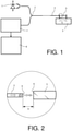
- the figure 1 represents the general synoptic of a sensor of this type. It comprises a broad-spectrum light source 1, part of the flux emitted by this source is sent into the measurement optical fiber 3 by means of a Y-shaped optical coupler denoted 2.
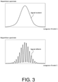
- a cylindrical rod 5 In front of the end 4 of this optical fiber, a cylindrical rod 5 has been placed in the axis of the optical fiber. The end of the fiber and the rod are made integral with a sample E to be measured by point connections which do not produce excessive stresses in the material. They are separated by a length defining the gauge length Lj.
- the two reflected signals having undergone different paths are phase shifted. This phase shift depends on the wavelength ⁇ of the signal and the distance Lc.
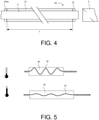
- An optical signal is obtained, the spectrum of which has periodic maxima and minima as represented on the picture 3 . That picture 3 has two representations. The top one represents the spectral distribution of the source at emission as a function of the wavelength ⁇ and the bottom one, the spectral distribution of the reflected signal as a function of the wavelength ⁇ .
- the reflected spectrum is said to be “fluted”.
- the spectrum is analyzed by a spectrometer 7 as seen in the figure 1 . From the position of the grooves, the analysis and measurement means 8 easily deduce the distance L.
- the light source is a diode of the "SLED” type, an acronym meaning “Superluminescent Light Emitting Diode” emitting at a wavelength close to 960 nanometers and whose width of the emission spectrum is approximately 50 nanometers. If the distance Lc equals 100 microns, one thus obtains about ten usable grooves.
- a sensor of this type must have an accuracy of the order of a micron.
- the realization of the sensor must be simple in order to ensure its resistance to extreme environments, while guaranteeing the precision of the measurements. It usually has an optical head and a fiber optic transport. Transport makes it possible to deport the measurement to an area where the irradiation and temperature constraints have dropped considerably.
- the actual optical head that is to say the part of the sensor comprising the Fabry-Perot cavity, is generally inserted into a metal encapsulation.
- the end of the fiber and the rod are fixed to this metal encapsulation by two first anchor points.
- the tube is secured to the object whose elongation is to be measured by two second anchor points.
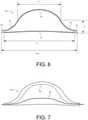
- the simplest and most robust design of the optical transport 10 is shown in the figure 4 . It consists in protecting the optical fiber 3 by a sheath 11 of stainless steel with a length L′. The fiber is held in its sheath by dots of ceramic glue 12 and 12a as seen on the figure 4 .
- the second attachment point 12a between the steel sheath and the optical head which corresponds to the attachment point farthest from the optical head, is located in an area where the temperature and radiation are greatly reduced compared to the area in which the optical head and the sample are located.
- This second attachment point between the steel sheath and the optical head is robust and absorbs the various stresses transmitted by the fiber during the manufacturing, assembly and test phases which could be transmitted to the attachment point 12 close to the cavity. .
- first attachment point 12 between the steel sheath and the optical head is less bulky and less resistant.
- the second attachment point 12bis between the steel sheath and the optical head thus avoids damaging the first attachment point 12, causing a modification of the cavity length Lc during the measurement phase.
- the difference in length between the fiber and the metal sheath can then cause, depending on the position of the single fixing point, a drift of the Fabry Perot measurement cavity or a strong variation in the length of the second cavity, which prevents good transmission of the signal on this second cavity, these two harmful effects possibly occurring simultaneously.
- the tensions generated risk modifying the length of the cavity Lc and damaging the fixing close to the cavity.
- a possible solution is to create, during assembly at room temperature, a reserve of expansion in the optical transport so that the optical fiber can retract freely without creating constraints at the level of the attachments of its sheath or of its protective envelope.
- the proposed solution takes into account the small volume available in particular near the sample and the need to avoid bringing a high thermal mass near the sensor.
- the solution is represented in figure 5 at two different temperatures symbolized on the left of the figure by thermometers.
- the optical fiber 15 is held in a closed enclosure 16 whose width is greater than the diameter of the optical fiber.
- the optical fiber forms a serpentine as seen in the representation at the top of the figure 5 .
- the box 16 expands, as well as the stainless steel sheath of the transport to which it is connected and the serpentine of the optical fiber 15 stretches without creating traction on the fixing points.
- the case or expansion reserve case according to the invention does not have these drawbacks. Its shape is designed to contain only one arch of optical fiber, whatever the difference in length between fiber and stainless steel sheath, so as to minimize the friction and possible snagging of the optical fiber on the enclosure walls during operating phases in severe environments during which the optical fiber can compact and undergo thermal cycles.
- the subject of the invention is an optical fiber sensor for measuring deformation intended to operate in a temperature range of a few hundred degrees, said sensor comprising a optical measuring head with Fabry-Perot cavity, an optical transport fiber and an expansion reserve case, the said case comprising a segment of the said optical transport fiber, characterized in that the internal thickness of the case is between one and a few millimeters, said case being flat and in the shape of a so-called policeman's hat, said shape comprising a central convex part and two symmetrical concave ends, the optical fiber free to form inside the hat one and only one arch, the segment of the optical fiber being, at most, tangent to the internal surfaces of the reserve case, whatever the temperature conditions.
- the optical fiber is made of silica, it comprises an aluminum sheath and the case is made of stainless steel.
- the optical fiber sensor for measuring elongation comprises an optical measuring head with a Fabry-Pérot cavity such as previously described, a transport optical fiber and a specific optical fiber expansion reserve.
- this sensor is arranged so as to measure elongations of the order of 150 microns over a gauge length of 15 mm with micron precision.
- This optical sensor is particularly intended to operate in harsh environments. This environment is characterized by high temperatures, of the order of several hundred degrees, and intense radiation levels both in terms of gamma radiation and sustained neutron doses.
- the figure 6 shows a cross-sectional view of this fiber optic expansion reserve 20.
- This expansion reserve has the form of a thin, flat, hollow case comprising a segment of the transport optical fiber. More precisely, the internal thickness of the case is close to the diameter of the transport optical fiber. This optical fiber is not represented on the figure 6 .
- the material of the case must be chosen in such a way as to withstand the severe environments of the sensors as described previously. It can be made of stainless steel, the optical fiber being made of silica and having an aluminum coating.
- the optical fiber When the temperature rises, the optical fiber undergoes two phenomena as it has been said, a weaker expansion than the transport sheath and compaction under the effect of radiation. In the end, its length in the case varies and this variation in length is absorbed by the height of the arch.
- a case as defined above can absorb a differential variation between expansion and maximum compaction of 12 millimeters.
Landscapes
- Physics & Mathematics (AREA)
- General Physics & Mathematics (AREA)
- Length Measuring Devices By Optical Means (AREA)
- Measuring Temperature Or Quantity Of Heat (AREA)
- Optical Transform (AREA)
Description
- Le domaine de l'invention est celui des capteurs de mesure de déplacement fonctionnant en environnement sévère. On entend par environnement sévère celui qui règne à l'intérieur des réacteurs nucléaires. Il est caractérisé par des températures élevées, de l'ordre de plusieurs centaines de degrés et des niveaux de radiations intenses tant au niveau du rayonnement gamma que des doses de neutrons supportées.
- L'instrumentation nucléaire pour les irradiations en réacteur de recherche fait appel à un certain nombre de mesures. On citera les mesures de température, de flux neutroniques, de rayonnement Gamma et d'élongation de certaines pièces en test dans le réacteur. Ces dernières mesures d'allongement sont essentiellement réalisées par des capteurs inductifs. Ces mesures peuvent également être réalisées par des capteurs à fibre optique qui présentent comme principaux avantages d'être moins encombrants, moins intrusifs et plus précis que les capteurs précédents.
- Ces capteurs optiques sont de type Fabry-Perot en lumière blanche. Le principe de fonctionnement des capteurs adaptés aux fortes température et radiations est exposé sur les
figures 1, 2 et3 . Lafigure 1 représente le synoptique général d'un capteur de ce type. Il comporte une source de lumière 1 à spectre large, une partie du flux émis par cette source est envoyée dans la fibre optique de mesure 3 au moyen d'un coupleur optique en Y noté 2. Devant l'extrémité 4 de cette fibre optique, on a disposé une tige cylindrique 5 dans l'axe de la fibre optique. L'extrémité de la fibre et la tige sont rendus solidaires d'un échantillon E à mesurer par des liaisons ponctuelles qui ne produisent pas de contraintes excessives dans le matériau. Elles sont séparées par une longueur définissant la longueur de jauge Lj. - L'extrémité 4 située au plus près de la fibre optique est réfléchissante. La
figure 2 représente une vue agrandie de cette partie du capteur. L'extrémité de la fibre optique et l'extrémité 6 de la tige 5 en regard constituent une cavité Fabry-Pérot de longueur Lc. La variation de la longueur Lj que l'on cherche à mesurer est égale à la variation de Lc. A titre d'ordre de grandeur, cette distance Lc vaut environ 100 microns. Sur lafigure 2 , les flèches représentent les différents signaux optiques émis et réfléchis. Une partie du signal optique est réfléchie par l'extrémité de la fibre optique. Une seconde partie du signal optique est réfléchie par la tige. Ces deux signaux se superposent et forment un système d'interférences. - Les deux signaux réfléchis ayant subi des parcours différents sont déphasés. Ce déphasage dépend de la longueur d'onde λ du signal et de la distance Lc. On obtient un signal optique dont le spectre présente des maxima et des minima périodiques comme représenté sur la
figure 3 . Cettefigure 3 comporte deux représentations. Celle du haut représente la répartition spectrale de la source à l'émission en fonction de la longueur d'onde λ et celle du bas, la répartition spectrale du signal réfléchi en fonction de la longueur d'onde λ. Le spectre réfléchi est dit « cannelé ». Le spectre est analysé par un spectromètre 7 comme on le voit sur lafigure 1 . De la position des cannelures, les moyens d'analyse et de mesure 8 déduisent facilement la distance L. A titre d'exemple, la source de lumière est une diode de type « SLED », acronyme signifiant « Superluminescent Light Emitting Diode » émettant à une longueur d'onde voisine de 960 nanomètres et dont la largeur du spectre d'émission vaut environ 50 nanomètres. Si la distance Lc vaut 100 microns, on obtient ainsi une dizaine de cannelures exploitables. - Plus précisément, le nombre Δk de franges brillantes entières ou de franges sombres entières entre deux longueurs d'onde λ1 et λ2 connues, la longueur d'onde λ2 étant supérieure à la longueur d'onde λ1, est reliée à la longueur de cavité LC selon la formule :

- Un capteur de ce type doit avoir une précision de l'ordre du micron. La réalisation du capteur doit être simple de façon à assurer sa résistance aux environnements extrêmes, tout en garantissant la précision des mesures. Il comporte généralement une tête optique et un transport à fibre optique. Le transport permet de déporter la mesure jusqu'à une zone où les contraintes d'irradiation et de température ont fortement baissé.
- La tête optique proprement dit, c'est-à-dire la partie du capteur comportant la cavité Fabry-Perot est généralement insérée dans une encapsulation métallique. L'extrémité de la fibre et la tige sont fixées à cette encapsulation métallique par deux premiers points d'ancrage. Le tube est rendu solidaire de l'objet dont on cherche à mesurer l'élongation par deux seconds points d'ancrage. On trouvera dans le brevet
FR 2 929 701 - La conception la plus simple et la plus robuste du transport optique 10 est représentée sur la
figure 4 . Elle consiste à protéger la fibre optique 3 par une gaine 11 d'acier inoxydable d'une longueur L'. La fibre est maintenue dans sa gaine par des points de colle céramique 12 et 12bis comme on le voit sur lafigure 4 . Le second point de fixation 12bis entre la gaine d'acier et la tête optique, qui correspond au point de fixation le plus éloigné de la tête optique, se situe dans une zone où la température et les radiations sont fortement réduites par rapport à la zone dans laquelle se situent la tête optique et l'échantillon. Ce second point de fixation entre la gaine d'acier et la tête optique est robuste et absorbe les diverses contraintes transmises par la fibre pendant les phases de fabrication, de montage et de tests qui pourraient se transmettre au point de fixation 12 proche de la cavité. En effet, le premier point de fixation 12 entre la gaine d'acier et la tête optique est moins volumineux et moins résistant. Le second point de fixation 12bis entre la gaine d'acier et la tête optique évite ainsi de détériorer le premier point de fixation 12, engendrant une modification de la longueur de cavité Lc pendant la phase de mesure. - Une façon d'éviter que des contraintes ne s'appliquent sur l'extrémité de fibre est proposée dans le brevet
US 2006/0233484 intitulé « Adhesive-assembled fiber-optic interferometer ». Cette solution présente un assemblage comportant une seconde cavité qui n'a pas de fonction de mesure mais découple mécaniquement la cavité de mesure de la fibre optique reliant la cavité de mesure à l'instrumentation. Il y a un seul point de fixation sur le segment entre les deux cavités. - Cette solution ne convient pas pour un fonctionnement en environnement sévère. En effet, lorsque ce transport est soumis aux environnements sévères du capteur, deux phénomènes se produisent : la gaine d'acier se dilate davantage que la fibre sous l'effet de la chaleur et la fibre optique se rétracte sous l'effet des radiations neutroniques intenses. On appelle ce dernier phénomène « compaction ». Les fibres optiques utilisées sont en silice. Le différentiel de longueur résultant peut atteindre plus de 1 pour cent de variation relative. Pour disposer cette seconde cavité dans une zone où la température et les radiations sont fortement réduites, il faut augmenter la distance entre les deux cavités. Le différentiel de longueur entre la fibre et la gaine métallique peut alors entrainer, selon la position du seul point de fixation, une dérive de la cavité Fabry Perot de mesure ou une forte variation de la longueur de la seconde cavité, qui empêche une bonne transmission du signal sur cette seconde cavité, ces deux effets néfastes pouvant se produire simultanément.
- Si les deux extrémités du transport comportent deux points de fixation, les tensions engendrées risquent de modifier la longueur de cavité Lc et de détériorer la fixation proche de la cavité.
- Pour résoudre le problème, une solution possible est de créer, lors du montage à température ambiante, une réserve de dilatation dans le transport optique de façon que la fibre optique puisse se rétracter librement sans créer de contraintes au niveau des attaches de sa gaine ou de son enveloppe de protection. La solution proposée tient compte du faible volume disponible en particulier à proximité de l'échantillon et de la nécessité d'éviter de rapporter une masse thermique élevée près du capteur.
- La solution est représentée en
figure 5 à deux températures différentes symbolisées à gauche de la figure par des thermomètres. La fibre optique 15 est maintenue dans une enceinte 16 fermée dont la largeur est supérieure au diamètre de la fibre optique. A froid, la fibre optique forme un serpentin comme on le voit sur la représentation du haut de lafigure 5 . A chaud, comme on le voit sur la représentation du bas de lafigure 5 , la boîte 16 se dilate, ainsi que la gaine d'acier inoxydable du transport à laquelle il est relié et le serpentin de la fibre optique 15 s'étire sans créer de tractions sur les points de fixation. Un des inconvénients de ce système est qu'il existe un risque que lors des divers cycles thermiques la fibre optique s'accroche aux parois de la boîte au lieu de reprendre la forme idéale dessinée, il peut alors se former une forte courbure locale pouvant endommager la fibre. Il est important que la fibre optique ne puisse s'appuyer localement sur les parois. - Le boitier ou l'étui de réserve de dilatation selon l'invention ne présente pas ces inconvénients. Sa forme est étudiée pour ne contenir qu'une seule arche de fibre optique, quel que soit le différentiel de longueur entre fibre et gaine d'acier inoxydable, de façon à minimiser au mieux les frottements et les accroches possibles de la fibre optique sur les parois du boitier pendant les phases de fonctionnement en environnement sévère pendant lesquelles la fibre optique peut se compacter et subir des cycles thermiques.
- Plus précisément, l'invention a pour objet un capteur à fibre optique de mesure de déformation destiné à fonctionner dans une plage de température de quelques centaines de degrés, ledit capteur comportant une tête optique de mesure à cavité Fabry-Perot, une fibre optique de transport et un étui de réserve de dilatation, ledit étui comportant un segment de ladite fibre optique de transport, caractérisé en ce que l'épaisseur intérieure de l'étui est comprise entre un et quelques millimètres, ledit étui étant plat et en forme dite de chapeau de gendarme, ladite forme comportant une partie centrale convexe et deux extrémités symétriques concaves, la fibre optique libre de former à l'intérieur du chapeau une et une seule arche, le segment de la fibre optique étant, au plus, tangent aux surfaces internes de l'étui de réserve, quelles que soient les conditions de température.
- Avantageusement, la fibre optique est en silice, elle comporte un gainage en aluminium et l'étui est en acier inoxydable.
- Avantageusement, la hauteur de l'étui de réserve de dilatation est environ le quart de sa largeur.
- Avantageusement, la hauteur de l'étui de réserve de dilatation est d'environ 20 millimètres.
- Avantageusement, le maintien de la fibre optique à l'extrémité du transport la plus éloignée de la tête optique de mesure est réalisé par une colle céramique haute température à proximité de la sortie de l'étui.
- L'invention sera mieux comprise et d'autres avantages apparaîtront à la lecture de la description qui va suivre donnée à titre non limitatif et grâce aux figures annexées parmi lesquelles :
- La
figure 1 représente le synoptique général d'un capteur de déplacement à cavité Fabry-Pérot ; - La
figure 2 représente une vue agrandie de la cavité Fabry-Pérot et de son fonctionnement ; - La
figure 3 représente le spectre de la source d'émission avant et après traversée de la cavité Fabry-Pérot ; - La
figure 4 représente une vue en coupe du transport optique ; - La
figure 5 représente un mode de réalisation d'une réserve de dilatation selon l'art antérieur ; - La
figure 6 représente un mode de réalisation d'une réserve de dilatation selon l'invention ; - La
figure 7 représente le fonctionnement de la réserve de dilatation selon l'invention. - Le capteur à fibre optique de mesure d'allongement selon l'invention comporte une tête optique de mesure à cavité Fabry-Pérot tel que précédemment décrit, une fibre optique de transport et une réserve de dilatation à fibre optique spécifique. Typiquement, ce capteur est agencé de façon à mesurer des allongements de l'ordre de 150 microns sur une longueur de jauge de 15 mm avec une précision du micron.
- Ce capteur optique est tout particulièrement destiné à fonctionner en environnement sévère. Cet environnement est caractérisé par des températures élevées, de l'ordre de plusieurs centaines de degrés, et des niveaux de radiations intenses tant au niveau du rayonnement gamma que des doses de neutrons supportées
- La
figure 6 représente une vue en coupe de cette réserve de dilatation 20 à fibre optique. Cette réserve de dilatation a la forme d'un étui creux et plat de faible épaisseur comportant un segment de la fibre optique de transport. Plus précisément, l'épaisseur interne de l'étui est voisine du diamètre de la fibre optique de transport. Cette fibre optique n'est pas représentée sur lafigure 6 . - Cet étui a une forme dite en « chapeau de gendarme », la partie haute de cette forme comportant une partie centrale convexe 21 et deux extrémités symétriques concaves 22, la fibre optique étant maintenue à une des deux extrémités 24 de l'étui et passant par la seconde extrémité 25 de l'étui, la fibre optique formant à l'intérieur du chapeau une et une seule arche dont la hauteur varie avec la dilatation ou la compaction de la fibre optique. La partie basse 23 de l'étui est faiblement concave.
- La géométrie de cet étui peut être caractérisée par un certain nombre de dimensions qui sont sa longueur LU hors embouts d'assemblage, sa longueur maximale LMAX, sa hauteur H au point d'inflexion séparant les parties concaves de la partie convexe, la longueur de la partie convexe LC. A titre d'exemple non limitatif, un étui selon l'invention peut avoir les caractéristiques géométriques suivantes, arrondies au dixième de millimètre :
Longueur LMAX : 66.0 mm Longueur LU : 60.0 mm Hauteur H : 9.2 mm Longueur LC : 38.3 mm Epaisseur intérieure : 1.2 mm Epaisseur totale : 2.5 mm - Le matériau de l'étui doit être choisi de façon à résister aux environnements sévères des capteurs tels que décrits précédemment. Il peut être réalisé en acier inoxydable, la fibre optique étant réalisée en silice et comportant un revêtement en aluminium.
- Ce boitier peut être réalisé en impression 3D par la technique de fusion sélective par laser, connue sous le terme de « SLM », acronyme signifiant « Selective Laser Melting ».
- Le maintien de la fibre optique à l'extrémité du transport la plus éloignée de la tête optique de mesure est réalisé, à 30 mm de la sortie de l'étui, par une colle céramique résistant à haute température, de l'ordre de quelques centaines de degrés.
- L'étui de réserve de dilatation est éloigné de la tête optique d'au moins 500 millimètres de façon que son échauffement propre ne parasite pas la mesure d'élongation réalisée par la tête optique, à une position telle qu'au-delà du point de fixation fibre/gaine éloigné de la tête optique, la dilatation thermique et la compaction soient négligeables, et telle que l'encombrement de cet étui soit acceptable à cette position. Le fonctionnement de cet étui est représenté sur la
figure 7 . Sur cette figure, on a représenté une vue en coupe de l'étui 20 et la fibre optique 30 à deux températures. La courbe en traits pointillés est représentative de la position de la fibre optique à basse température et la courbe en trait plein est représentative de la position de la fibre optique à haute température. Ces deux courbes sont en forme d'arche. Lorsque la température monte, la fibre optique subit deux phénomènes comme il a été dit, une dilatation plus faible que la gaine du transport et une compaction sous l'effet des radiations. Au final, sa longueur dans l'étui varie et cette variation de longueur est absorbée par la hauteur de l'arche. Un étui tel que défini précédemment peut absorber une variation différentielle entre la dilatation et la compaction maximale de 12 millimètres. - L'intérêt de cette forme en arche est que la fibre optique se déplace à l'intérieur de l'étui sans frottement important de façon à éviter tout risque d'accroche de la fibre optique susceptible de créer des contraintes mécaniques excessives sur la fibre optique. La fibre optique reste, au plus, tangente aux surfaces avec lesquelles elle est en contact. Le capteur peut ainsi subir un grand nombre de cycles thermiques sans détérioration, augmentant ainsi sa durée de vie et sa fiabilité de façon significative.
Claims (5)
- Capteur à fibre optique de mesure de déformation destiné à fonctionner dans une plage de température de quelques centaines de degrés, ledit capteur comportant une tête optique de mesure à cavité Fabry-Perot, une fibre optique de transport et un étui (20) de réserve de dilatation, ledit étui comportant un segment de ladite fibre optique de transport, caractérisé en ce que l'épaisseur intérieure de l'étui est voisine du diamètre de la fibre optique de transport, ledit étui étant plat et en forme dite de chapeau de gendarme, ladite forme comportant une partie centrale convexe (21) et deux extrémités symétriques concaves (22), la fibre optique étant libre de former à l'intérieur du chapeau une et une seule arche, le segment de la fibre optique étant, au plus, tangent aux surfaces internes de l'étui de réserve, quelles que soient les conditions de température.
- Capteur à fibre optique selon la revendication 1, caractérisé en ce que la fibre optique est en silice, qu'elle comporte un gainage en aluminium et que l'étui est en acier inoxydable.
- Capteur à fibre optique selon l'une des revendications précédentes, caractérisé en ce que la hauteur de l'étui de réserve de dilatation est le quart de sa largeur.
- Capteur à fibre optique selon la revendication 3, caractérisé en ce que la hauteur de l'étui de réserve de dilatation est 20 millimètres.
- Capteur à fibre optique selon l'une des revendications précédentes, caractérisé en ce que le maintien de la fibre optique à l'extrémité du transport la plus éloignée de la tête optique de mesure est réalisé à proximité de la sortie de l'étui par une colle céramique haute température, de l'ordre de quelques centaines de degrés.
Priority Applications (1)
| Application Number | Priority Date | Filing Date | Title |
|---|---|---|---|
| PL19715506T PL3775761T3 (pl) | 2018-04-13 | 2019-04-10 | Czujnik światłowodowy do pomiaru odkształceń w trudnych warunkach środowiskowych |
Applications Claiming Priority (2)
| Application Number | Priority Date | Filing Date | Title |
|---|---|---|---|
| FR1853233A FR3080175B1 (fr) | 2018-04-13 | 2018-04-13 | Capteur a fibre optique de mesure de deformation fonctionnant en environnement severe |
| PCT/EP2019/059047 WO2019197447A1 (fr) | 2018-04-13 | 2019-04-10 | Capteur à fibre optique de mesure de déformation fonctionnant en environnement sévère |
Publications (2)
| Publication Number | Publication Date |
|---|---|
| EP3775761A1 EP3775761A1 (fr) | 2021-02-17 |
| EP3775761B1 true EP3775761B1 (fr) | 2022-02-23 |
Family
ID=65243654
Family Applications (1)
| Application Number | Title | Priority Date | Filing Date |
|---|---|---|---|
| EP19715506.2A Active EP3775761B1 (fr) | 2018-04-13 | 2019-04-10 | Capteur à fibre optique de mesure de déformation en environnement sévère |
Country Status (5)
| Country | Link |
|---|---|
| US (1) | US11099005B2 (fr) |
| EP (1) | EP3775761B1 (fr) |
| FR (1) | FR3080175B1 (fr) |
| PL (1) | PL3775761T3 (fr) |
| WO (1) | WO2019197447A1 (fr) |
Families Citing this family (1)
| Publication number | Priority date | Publication date | Assignee | Title |
|---|---|---|---|---|
| CN115046489B (zh) * | 2022-03-25 | 2023-04-18 | 武汉理工大学 | 一种光纤高温应变传感器预紧量控制装置和控制方法 |
Family Cites Families (7)
| Publication number | Priority date | Publication date | Assignee | Title |
|---|---|---|---|---|
| CA2105605A1 (fr) * | 1993-09-07 | 1995-03-08 | Zhuo Jun Lu | Systeme a reseau de capteurs a fibres optiques servant a la mesure des deformations et des temperatures |
| US6141087A (en) * | 1998-12-18 | 2000-10-31 | General Electric Company | System and method for measuring engine rotor thrust using Fabry-Perot fiber sensor |
| CA2541028A1 (fr) | 2005-03-24 | 2006-09-24 | Opsens Inc. | Interferometre a fibres optiques lie par adhesif |
| US7515781B2 (en) * | 2005-07-22 | 2009-04-07 | Exxonmobil Research And Engineering Company | Fiber optic, strain-tuned, material alteration sensor |
| FR2929701B1 (fr) * | 2008-04-07 | 2011-01-07 | Commissariat Energie Atomique | Capteur d'allongement a fibre optique. |
| GB2481039A (en) * | 2010-06-09 | 2011-12-14 | Rolls Royce Plc | Temperature, Pressure and Neutron Fluence Measurment |
| FR3034207B1 (fr) * | 2015-03-27 | 2018-01-19 | Thales | Dispositif de capteur a fibre optique |
-
2018
- 2018-04-13 FR FR1853233A patent/FR3080175B1/fr active Active
-
2019
- 2019-04-10 WO PCT/EP2019/059047 patent/WO2019197447A1/fr not_active Ceased
- 2019-04-10 PL PL19715506T patent/PL3775761T3/pl unknown
- 2019-04-10 EP EP19715506.2A patent/EP3775761B1/fr active Active
- 2019-04-10 US US17/045,719 patent/US11099005B2/en active Active
Also Published As
| Publication number | Publication date |
|---|---|
| FR3080175B1 (fr) | 2020-03-20 |
| EP3775761A1 (fr) | 2021-02-17 |
| US11099005B2 (en) | 2021-08-24 |
| FR3080175A1 (fr) | 2019-10-18 |
| PL3775761T3 (pl) | 2022-04-04 |
| WO2019197447A1 (fr) | 2019-10-17 |
| US20210156673A1 (en) | 2021-05-27 |
Similar Documents
| Publication | Publication Date | Title |
|---|---|---|
| EP2235480B1 (fr) | Capteur optique | |
| EP2791640B1 (fr) | Ressort avec capteur de deformation integre | |
| EP3425344B1 (fr) | Capteur de deplacement avec micro-résonateur en anneau segmenté | |
| EP0033048A1 (fr) | Interféromètre à cavité optique accordable comprenant une fibre optique monomode et application au filtrage et à la spectrographie | |
| EP3844466B1 (fr) | Capteur de température à réseau de bragg insensible aux déformations | |
| EP3274670B1 (fr) | Procédé de fabrication d'un dispositif de capteur à fibre optique | |
| FR3087257A1 (fr) | Capteur a fibre optique a reseau de bragg a haute tenue en temperature et son procede de fabrication | |
| EP3276337A1 (fr) | Dispositif optique à micro-résonateur en anneau segmenté | |
| FR2990754A1 (fr) | Dispositif de mesure des amplitudes vibratoires des sommets d'aubes dans une turbomachine | |
| EP3433575B1 (fr) | Capteur de courbure a fibre optique et dispositif de mesure comprenant ledit capteur | |
| WO2019197447A1 (fr) | Capteur à fibre optique de mesure de déformation fonctionnant en environnement sévère | |
| FR2849694A1 (fr) | Capteur de deviation | |
| EP0971203A1 (fr) | Procédé et dispositif pour la mesure de l'épaisseur d'un matériau transparent | |
| FR3126153A1 (fr) | Capteur optique amélioré pour mesurer un déplacement d’une pièce | |
| CH425245A (fr) | Procédé de mesure d'une dimension linéaire d'un objet | |
| FR3125879A1 (fr) | Dispositif de mesure de pression hydrostatique, notamment absolue et/ou de température et procédé de mesure associé | |
| FR2921482A1 (fr) | Transducteur a fibre optique multimode et a couplage de modes, procede de realisation | |
| WO2025131752A1 (fr) | Dispositif de mesure de variations d'effort, de deformations mecaniques, de pressions hydrostatiques et de temperature, et procede de mesure associe | |
| BE1020906A3 (fr) | Capteur d'allongement a fibre optique. | |
| WO2022123182A1 (fr) | Dispositif de mesure de deplacement mecanique d'une piece | |
| FR3157531A1 (fr) | Dispositif de mesure de variations d’effort, de déformations mécaniques, de pressions hydrostatiques et de température, et procédé de mesure associé | |
| FR3048692A1 (fr) | Installation de production de verre plat comprenant une installation de mesure en continu de la temperature du verre et procede de reglage d'une telle installation de mesure | |
| FR3039893A1 (fr) | Dispositif de mesure de niveau de liquide par reflectrometrie optique, structure comprenant un tel dispositif et procede de mesure correspondant | |
| EP3489629A1 (fr) | Dispositif de cartographie de temperature et de deformation d'une structure, notamment d'une paroi de crayon de combustible nucleaire | |
| US20260036472A1 (en) | Optical sensing method and optical sensor system for an optical sensing method |
Legal Events
| Date | Code | Title | Description |
|---|---|---|---|
| STAA | Information on the status of an ep patent application or granted ep patent |
Free format text: STATUS: UNKNOWN |
|
| STAA | Information on the status of an ep patent application or granted ep patent |
Free format text: STATUS: THE INTERNATIONAL PUBLICATION HAS BEEN MADE |
|
| PUAI | Public reference made under article 153(3) epc to a published international application that has entered the european phase |
Free format text: ORIGINAL CODE: 0009012 |
|
| STAA | Information on the status of an ep patent application or granted ep patent |
Free format text: STATUS: REQUEST FOR EXAMINATION WAS MADE |
|
| 17P | Request for examination filed |
Effective date: 20201012 |
|
| AK | Designated contracting states |
Kind code of ref document: A1 Designated state(s): AL AT BE BG CH CY CZ DE DK EE ES FI FR GB GR HR HU IE IS IT LI LT LU LV MC MK MT NL NO PL PT RO RS SE SI SK SM TR |
|
| AX | Request for extension of the european patent |
Extension state: BA ME |
|
| DAV | Request for validation of the european patent (deleted) | ||
| DAX | Request for extension of the european patent (deleted) | ||
| GRAP | Despatch of communication of intention to grant a patent |
Free format text: ORIGINAL CODE: EPIDOSNIGR1 |
|
| STAA | Information on the status of an ep patent application or granted ep patent |
Free format text: STATUS: GRANT OF PATENT IS INTENDED |
|
| INTG | Intention to grant announced |
Effective date: 20211126 |
|
| GRAS | Grant fee paid |
Free format text: ORIGINAL CODE: EPIDOSNIGR3 |
|
| GRAA | (expected) grant |
Free format text: ORIGINAL CODE: 0009210 |
|
| STAA | Information on the status of an ep patent application or granted ep patent |
Free format text: STATUS: THE PATENT HAS BEEN GRANTED |
|
| AK | Designated contracting states |
Kind code of ref document: B1 Designated state(s): AL AT BE BG CH CY CZ DE DK EE ES FI FR GB GR HR HU IE IS IT LI LT LU LV MC MK MT NL NO PL PT RO RS SE SI SK SM TR |
|
| REG | Reference to a national code |
Ref country code: GB Ref legal event code: FG4D Free format text: NOT ENGLISH |
|
| REG | Reference to a national code |
Ref country code: CH Ref legal event code: EP |
|
| REG | Reference to a national code |
Ref country code: AT Ref legal event code: REF Ref document number: 1470794 Country of ref document: AT Kind code of ref document: T Effective date: 20220315 |
|
| REG | Reference to a national code |
Ref country code: IE Ref legal event code: FG4D Free format text: LANGUAGE OF EP DOCUMENT: FRENCH |
|
| REG | Reference to a national code |
Ref country code: DE Ref legal event code: R096 Ref document number: 602019011891 Country of ref document: DE |
|
| REG | Reference to a national code |
Ref country code: NL Ref legal event code: FP |
|
| REG | Reference to a national code |
Ref country code: LT Ref legal event code: MG9D |
|
| REG | Reference to a national code |
Ref country code: AT Ref legal event code: MK05 Ref document number: 1470794 Country of ref document: AT Kind code of ref document: T Effective date: 20220223 |
|
| PG25 | Lapsed in a contracting state [announced via postgrant information from national office to epo] |
Ref country code: SE Free format text: LAPSE BECAUSE OF FAILURE TO SUBMIT A TRANSLATION OF THE DESCRIPTION OR TO PAY THE FEE WITHIN THE PRESCRIBED TIME-LIMIT Effective date: 20220223 Ref country code: RS Free format text: LAPSE BECAUSE OF FAILURE TO SUBMIT A TRANSLATION OF THE DESCRIPTION OR TO PAY THE FEE WITHIN THE PRESCRIBED TIME-LIMIT Effective date: 20220223 Ref country code: PT Free format text: LAPSE BECAUSE OF FAILURE TO SUBMIT A TRANSLATION OF THE DESCRIPTION OR TO PAY THE FEE WITHIN THE PRESCRIBED TIME-LIMIT Effective date: 20220623 Ref country code: NO Free format text: LAPSE BECAUSE OF FAILURE TO SUBMIT A TRANSLATION OF THE DESCRIPTION OR TO PAY THE FEE WITHIN THE PRESCRIBED TIME-LIMIT Effective date: 20220523 Ref country code: LT Free format text: LAPSE BECAUSE OF FAILURE TO SUBMIT A TRANSLATION OF THE DESCRIPTION OR TO PAY THE FEE WITHIN THE PRESCRIBED TIME-LIMIT Effective date: 20220223 Ref country code: HR Free format text: LAPSE BECAUSE OF FAILURE TO SUBMIT A TRANSLATION OF THE DESCRIPTION OR TO PAY THE FEE WITHIN THE PRESCRIBED TIME-LIMIT Effective date: 20220223 Ref country code: ES Free format text: LAPSE BECAUSE OF FAILURE TO SUBMIT A TRANSLATION OF THE DESCRIPTION OR TO PAY THE FEE WITHIN THE PRESCRIBED TIME-LIMIT Effective date: 20220223 Ref country code: BG Free format text: LAPSE BECAUSE OF FAILURE TO SUBMIT A TRANSLATION OF THE DESCRIPTION OR TO PAY THE FEE WITHIN THE PRESCRIBED TIME-LIMIT Effective date: 20220523 |
|
| PG25 | Lapsed in a contracting state [announced via postgrant information from national office to epo] |
Ref country code: LV Free format text: LAPSE BECAUSE OF FAILURE TO SUBMIT A TRANSLATION OF THE DESCRIPTION OR TO PAY THE FEE WITHIN THE PRESCRIBED TIME-LIMIT Effective date: 20220223 Ref country code: GR Free format text: LAPSE BECAUSE OF FAILURE TO SUBMIT A TRANSLATION OF THE DESCRIPTION OR TO PAY THE FEE WITHIN THE PRESCRIBED TIME-LIMIT Effective date: 20220524 Ref country code: FI Free format text: LAPSE BECAUSE OF FAILURE TO SUBMIT A TRANSLATION OF THE DESCRIPTION OR TO PAY THE FEE WITHIN THE PRESCRIBED TIME-LIMIT Effective date: 20220223 Ref country code: AT Free format text: LAPSE BECAUSE OF FAILURE TO SUBMIT A TRANSLATION OF THE DESCRIPTION OR TO PAY THE FEE WITHIN THE PRESCRIBED TIME-LIMIT Effective date: 20220223 |
|
| PG25 | Lapsed in a contracting state [announced via postgrant information from national office to epo] |
Ref country code: IS Free format text: LAPSE BECAUSE OF FAILURE TO SUBMIT A TRANSLATION OF THE DESCRIPTION OR TO PAY THE FEE WITHIN THE PRESCRIBED TIME-LIMIT Effective date: 20220623 |
|
| PG25 | Lapsed in a contracting state [announced via postgrant information from national office to epo] |
Ref country code: SM Free format text: LAPSE BECAUSE OF FAILURE TO SUBMIT A TRANSLATION OF THE DESCRIPTION OR TO PAY THE FEE WITHIN THE PRESCRIBED TIME-LIMIT Effective date: 20220223 Ref country code: SK Free format text: LAPSE BECAUSE OF FAILURE TO SUBMIT A TRANSLATION OF THE DESCRIPTION OR TO PAY THE FEE WITHIN THE PRESCRIBED TIME-LIMIT Effective date: 20220223 Ref country code: RO Free format text: LAPSE BECAUSE OF FAILURE TO SUBMIT A TRANSLATION OF THE DESCRIPTION OR TO PAY THE FEE WITHIN THE PRESCRIBED TIME-LIMIT Effective date: 20220223 Ref country code: EE Free format text: LAPSE BECAUSE OF FAILURE TO SUBMIT A TRANSLATION OF THE DESCRIPTION OR TO PAY THE FEE WITHIN THE PRESCRIBED TIME-LIMIT Effective date: 20220223 Ref country code: DK Free format text: LAPSE BECAUSE OF FAILURE TO SUBMIT A TRANSLATION OF THE DESCRIPTION OR TO PAY THE FEE WITHIN THE PRESCRIBED TIME-LIMIT Effective date: 20220223 |
|
| REG | Reference to a national code |
Ref country code: DE Ref legal event code: R119 Ref document number: 602019011891 Country of ref document: DE |
|
| PG25 | Lapsed in a contracting state [announced via postgrant information from national office to epo] |
Ref country code: AL Free format text: LAPSE BECAUSE OF FAILURE TO SUBMIT A TRANSLATION OF THE DESCRIPTION OR TO PAY THE FEE WITHIN THE PRESCRIBED TIME-LIMIT Effective date: 20220223 |
|
| REG | Reference to a national code |
Ref country code: CH Ref legal event code: PL |
|
| PLBE | No opposition filed within time limit |
Free format text: ORIGINAL CODE: 0009261 |
|
| STAA | Information on the status of an ep patent application or granted ep patent |
Free format text: STATUS: NO OPPOSITION FILED WITHIN TIME LIMIT |
|
| PG25 | Lapsed in a contracting state [announced via postgrant information from national office to epo] |
Ref country code: MC Free format text: LAPSE BECAUSE OF FAILURE TO SUBMIT A TRANSLATION OF THE DESCRIPTION OR TO PAY THE FEE WITHIN THE PRESCRIBED TIME-LIMIT Effective date: 20220223 Ref country code: LU Free format text: LAPSE BECAUSE OF NON-PAYMENT OF DUE FEES Effective date: 20220410 Ref country code: LI Free format text: LAPSE BECAUSE OF NON-PAYMENT OF DUE FEES Effective date: 20220430 Ref country code: DE Free format text: LAPSE BECAUSE OF NON-PAYMENT OF DUE FEES Effective date: 20221103 Ref country code: CH Free format text: LAPSE BECAUSE OF NON-PAYMENT OF DUE FEES Effective date: 20220430 |
|
| 26N | No opposition filed |
Effective date: 20221124 |
|
| PG25 | Lapsed in a contracting state [announced via postgrant information from national office to epo] |
Ref country code: SI Free format text: LAPSE BECAUSE OF FAILURE TO SUBMIT A TRANSLATION OF THE DESCRIPTION OR TO PAY THE FEE WITHIN THE PRESCRIBED TIME-LIMIT Effective date: 20220223 |
|
| PG25 | Lapsed in a contracting state [announced via postgrant information from national office to epo] |
Ref country code: IE Free format text: LAPSE BECAUSE OF NON-PAYMENT OF DUE FEES Effective date: 20220410 |
|
| PG25 | Lapsed in a contracting state [announced via postgrant information from national office to epo] |
Ref country code: IT Free format text: LAPSE BECAUSE OF FAILURE TO SUBMIT A TRANSLATION OF THE DESCRIPTION OR TO PAY THE FEE WITHIN THE PRESCRIBED TIME-LIMIT Effective date: 20220223 |
|
| PG25 | Lapsed in a contracting state [announced via postgrant information from national office to epo] |
Ref country code: MK Free format text: LAPSE BECAUSE OF FAILURE TO SUBMIT A TRANSLATION OF THE DESCRIPTION OR TO PAY THE FEE WITHIN THE PRESCRIBED TIME-LIMIT Effective date: 20220223 Ref country code: CY Free format text: LAPSE BECAUSE OF FAILURE TO SUBMIT A TRANSLATION OF THE DESCRIPTION OR TO PAY THE FEE WITHIN THE PRESCRIBED TIME-LIMIT Effective date: 20220223 |
|
| PG25 | Lapsed in a contracting state [announced via postgrant information from national office to epo] |
Ref country code: HU Free format text: LAPSE BECAUSE OF FAILURE TO SUBMIT A TRANSLATION OF THE DESCRIPTION OR TO PAY THE FEE WITHIN THE PRESCRIBED TIME-LIMIT; INVALID AB INITIO Effective date: 20190410 |
|
| PG25 | Lapsed in a contracting state [announced via postgrant information from national office to epo] |
Ref country code: TR Free format text: LAPSE BECAUSE OF FAILURE TO SUBMIT A TRANSLATION OF THE DESCRIPTION OR TO PAY THE FEE WITHIN THE PRESCRIBED TIME-LIMIT Effective date: 20220223 |
|
| PG25 | Lapsed in a contracting state [announced via postgrant information from national office to epo] |
Ref country code: MT Free format text: LAPSE BECAUSE OF FAILURE TO SUBMIT A TRANSLATION OF THE DESCRIPTION OR TO PAY THE FEE WITHIN THE PRESCRIBED TIME-LIMIT Effective date: 20220223 |
|
| PGFP | Annual fee paid to national office [announced via postgrant information from national office to epo] |
Ref country code: PL Payment date: 20250328 Year of fee payment: 7 |
|
| PGFP | Annual fee paid to national office [announced via postgrant information from national office to epo] |
Ref country code: NL Payment date: 20250423 Year of fee payment: 7 |
|
| PGFP | Annual fee paid to national office [announced via postgrant information from national office to epo] |
Ref country code: GB Payment date: 20250424 Year of fee payment: 7 |
|
| PGFP | Annual fee paid to national office [announced via postgrant information from national office to epo] |
Ref country code: BE Payment date: 20250417 Year of fee payment: 7 |
|
| PGFP | Annual fee paid to national office [announced via postgrant information from national office to epo] |
Ref country code: FR Payment date: 20250422 Year of fee payment: 7 |
|
| PGFP | Annual fee paid to national office [announced via postgrant information from national office to epo] |
Ref country code: CZ Payment date: 20260327 Year of fee payment: 8 |