EP3775568B1 - Strömungsmaschine, insbesondere verdichtereinrichtung - Google Patents
Strömungsmaschine, insbesondere verdichtereinrichtung Download PDFInfo
- Publication number
- EP3775568B1 EP3775568B1 EP19711314.5A EP19711314A EP3775568B1 EP 3775568 B1 EP3775568 B1 EP 3775568B1 EP 19711314 A EP19711314 A EP 19711314A EP 3775568 B1 EP3775568 B1 EP 3775568B1
- Authority
- EP
- European Patent Office
- Prior art keywords
- bearing
- medium
- pressure
- shaft
- turbomachine
- Prior art date
- Legal status (The legal status is an assumption and is not a legal conclusion. Google has not performed a legal analysis and makes no representation as to the accuracy of the status listed.)
- Active
Links
Images

Classifications
-
- F—MECHANICAL ENGINEERING; LIGHTING; HEATING; WEAPONS; BLASTING
- F04—POSITIVE - DISPLACEMENT MACHINES FOR LIQUIDS; PUMPS FOR LIQUIDS OR ELASTIC FLUIDS
- F04D—NON-POSITIVE-DISPLACEMENT PUMPS
- F04D29/00—Details, component parts, or accessories
- F04D29/05—Shafts or bearings, or assemblies thereof, specially adapted for elastic fluid pumps
- F04D29/056—Bearings
- F04D29/057—Bearings hydrostatic; hydrodynamic
-
- F—MECHANICAL ENGINEERING; LIGHTING; HEATING; WEAPONS; BLASTING
- F04—POSITIVE - DISPLACEMENT MACHINES FOR LIQUIDS; PUMPS FOR LIQUIDS OR ELASTIC FLUIDS
- F04D—NON-POSITIVE-DISPLACEMENT PUMPS
- F04D29/00—Details, component parts, or accessories
- F04D29/05—Shafts or bearings, or assemblies thereof, specially adapted for elastic fluid pumps
- F04D29/051—Axial thrust balancing
- F04D29/0513—Axial thrust balancing hydrostatic; hydrodynamic thrust bearings
-
- F—MECHANICAL ENGINEERING; LIGHTING; HEATING; WEAPONS; BLASTING
- F04—POSITIVE - DISPLACEMENT MACHINES FOR LIQUIDS; PUMPS FOR LIQUIDS OR ELASTIC FLUIDS
- F04D—NON-POSITIVE-DISPLACEMENT PUMPS
- F04D29/00—Details, component parts, or accessories
- F04D29/05—Shafts or bearings, or assemblies thereof, specially adapted for elastic fluid pumps
- F04D29/056—Bearings
-
- F—MECHANICAL ENGINEERING; LIGHTING; HEATING; WEAPONS; BLASTING
- F04—POSITIVE - DISPLACEMENT MACHINES FOR LIQUIDS; PUMPS FOR LIQUIDS OR ELASTIC FLUIDS
- F04D—NON-POSITIVE-DISPLACEMENT PUMPS
- F04D29/00—Details, component parts, or accessories
- F04D29/26—Rotors specially for elastic fluids
- F04D29/28—Rotors specially for elastic fluids for centrifugal or helico-centrifugal pumps for radial-flow or helico-centrifugal pumps
- F04D29/284—Rotors specially for elastic fluids for centrifugal or helico-centrifugal pumps for radial-flow or helico-centrifugal pumps for compressors
Definitions
- the invention relates to a turbomachine, in particular a compressor device, having the features of the preamble of claim 1.
- Such a turbomachine is through the DE 10 2015 007 379 A1 known.
- This turbomachine has at least one bearing device for a rotatably arranged shaft.
- the bearing device has at least one bearing element for the radial and/or axial bearing of the shaft.
- the at least one bearing element can be acted upon by a pressurized gaseous medium for bearing the shaft.
- the shaft is connected to a drivable or driven flow element which is arranged in a housing which at least partially surrounds it.
- the pressurized medium can be fed at least indirectly from the turbomachine to the at least one bearing element.
- the flow element has at least one pressure outlet hole for the medium, via which the medium can be fed at least indirectly to the at least one bearing device.
- the at least one pressure outlet hole is at least indirectly connected to the at least one bearing device via at least one pressure line for the medium.
- the turbomachine according to the invention in particular a compressor device, with the features of claim 1 has the advantage that the supply of the medium to the at least one bearing device is improved.
- the flow element has a compressor wheel designed in a radial design, with the at least one pressure outlet bore on a pitch circle diameter is arranged around the axis of rotation of the shaft and interacts with an arranged in a separate component ring groove, whose side facing away from the at least one passage bore is connected to the at least one bearing device.
- Such a configuration has the advantage that when the compressor wheel rotates, the pressure outlet bore is arranged at least at times in operative connection with the annular groove and thus with the bearing device.
- a pressure accumulator designed as a separate component is arranged in the flow path of the at least one pressure line.
- the pressure accumulator ensures that there is sufficient (gaseous) medium available to support the shaft when the volume or pressure of the medium is temporarily low.
- the at least one bearing device has a pressure control device is connected upstream, which regulates the pressure or the quantity of the medium that can be fed to the storage device. In this way, in particular, excessive pressures of the medium that may have a negative effect on the bearing of the shaft are avoided.
- the separate component is designed in the shape of a ring or disk and is arranged stationary in relation to the flow element, that the at least one pressure outlet bore is designed as a through bore that extends between two opposite axial end faces of the flow element, and that the annular groove is designed as a circular annular groove running radially around the axis of rotation.
- the annular groove is designed as a circular annular groove running radially around the axis of rotation.
- a further structural design that reduces the cost of the bearing device provides that the bearing device is an axial bearing that acts on opposite end faces of a bearing disk connected to the shaft, and that the medium acts only on the end face of the bearing disk that faces the flow element.
- the bearing device is either supplied by another medium source or by a differently constructed bearing element, e.g. a film bearing, a bearing via spiral grooves or the like.
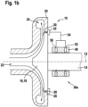
- the in the Fig. 1a and 1b The highly simplified flow machine not according to the invention is, for example, a component of a fuel cell system, an air conditioning system, a heat pump, a turbocharger, a turbine for a fuel cell system or a heat recovery turbine.
- the turbomachine is designed in the form of a compressor device 10 .
- Compressor device 10 includes a shaft 14 mounted on an axis of rotation 12, at one end of which a compressor stage 16 in the form of a compressor wheel 18 designed in a radial design is connected to shaft 14 in a rotationally fixed manner.
- the compressor stage 16 or the compressor wheel 18 is surrounded by a housing 20, which has an inlet area 22, through which gaseous medium, in particular air, is sucked into the compressor device 10, and when the shaft 14 rotates about the axis of rotation 12 by the Compressor stage 16 is compressed or increased in pressure, so that it exits under increased pressure in the region of an outlet region 24 of the housing 20 and can be supplied to a consumer, not shown.
- a radially encircling leakage gap 30 is formed between an edge region 26 of the compressor wheel 18 that runs radially around the axis of rotation 12 and a receiving opening 28 for the compressor wheel 18 in the housing 20, through which the medium, which has an increased pressure compared to the inlet region 22, can escape.
- the area of leakage gap 30 on the side facing away from housing 20 is surrounded by an annular collecting element 32 that is open towards leakage gap 30 and via which the medium emerging from leakage gap 30 can be fed directly to a bearing device 36 for shaft 14 via at least one pressure line 34 is.
- the storage device 36 is in the Fig. 1a designed as an axial bearing and has annular bearing elements 40, 42 arranged on two opposite end faces of a bearing disk 38 connected in a rotationally fixed manner to the shaft 14.
- the two bearing elements 40, 42 each have supply bores 44, 46, via which the pressurized medium from the pressure line 34 acts on the end faces of the bearing ring 38 and provides a corresponding pressure cushion in order to axially support the shaft 14 with respect to the housing 20 to allow.
- the bearing device 36a is designed as a radial bearing and comprises a bearing element 48 that radially encloses the shaft 14 and can be supplied directly with pressurized medium from the leakage gap 30 via feed bores 50, 52 and the at least one pressure line 34.
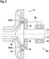
- a compressor wheel 55 has at least one, but preferably a plurality of pressure outlet bores 56 in the form of through bores 58, which are arranged at equal angular intervals on a pitch circle diameter around the axis of rotation 12 and extend parallel to the shaft 14.
- the pressure outlet bores 56 connect the end face of the compressor wheel 55 which faces the housing 20 and on which the pressurized medium is present, with the rear end face 60 of the compressor wheel 55.
- the radial distance of the pressure outlet bores 56 from the axis of rotation 12 determines the level of pressure of the medium for the bearing device 36a.
- the compressor wheel 55 is positioned on the side facing away from the housing 20 , at least in the region of the pressure outlet bores 56 , overlapping an annular, stationary element 62 .
- the element 62 has, on the same pitch circle diameter as the pressure outlet bores 56, a radially circumferential annular groove 64, which in turn is arranged in an operative connection via at least one pressure line 66 with the bearing device 36a.
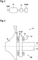
- the at least one pressure line 34, 66 is connected to the bearing device 36, 36a with the interposition of a pressure accumulator 70 and a pressure control device 72.
- Last is in the 4 the case is shown in which the bearing ring 38 of the bearing device 36b has a bearing element 40 on an end face facing the compressor stage 16, which is supplied with pressurized medium by the compressor device 10, while the other end face of the bearing ring 38 is connected to the bearing element 76 either via another (pressure) source 74 is applied in the direction of the housing 20 force.
- the bearing element 76 can also be a bearing element 76 which is not designed as a bearing element 76 subjected to gas pressure.
Landscapes
- Engineering & Computer Science (AREA)
- Mechanical Engineering (AREA)
- General Engineering & Computer Science (AREA)
- Physics & Mathematics (AREA)
- Fluid Mechanics (AREA)
- Structures Of Non-Positive Displacement Pumps (AREA)
Description
- Die Erfindung betrifft eine Strömungsmaschine, insbesondere eine Verdichtereinrichtung, mit den Merkmalen des Oberbegriffs des Anspruchs 1.
- Eine derartige Strömungsmaschine ist durch die
DE 10 2015 007 379 A1 bekannt. Diese Strömungsmaschine weist wenigstens eine Lagereinrichtung für eine drehbar angeordnete Welle auf. Die Lagereinrichtung weist wenigstens ein Lagerelement zur radialen und/oder axialen Lagerung der Welle auf. Das wenigstens eine Lagerelement ist mit unter Druck stehendem gasförmigem Medium zur Lagerung der Welle beaufschlagbar. Die Welle ist mit einem antreibbaren oder angetriebenen Ströumgselement verbunden, das in einem dieses zumindest teilweise umgebenden Gehäuse angeordnet ist. Das unter Druck stehende Medium ist zumindest mittelbar von der Strömungsmaschine dem wenigstens einen Lagerelement zuführbar. Das Strömungselement weist wenigstens eine Druckauslassbohrung für das Medium auf, über die das Medium zumindest mittelbar der wenigstens einen Lagereinrichtung zuführbar ist. Die wenigstens eine Druckauslassbohrung ist zumindest mittelbar über wenigstens eine Druckleitung für das Medium mit der wenigstens einen Lagereinrichtung verbunden. - Die erfindungsgemäße Strömungsmaschine, insbesondere Verdichtereinrichtung, mit den Merkmalen des Anspruchs 1 hat den Vorteil, dass die Zuführung des Mediums zur wenigstens einen Lagereinrichtung verbessert ist. Hierbei weist das Strömungselement ein in radialer Bauweise ausgebildetes Verdichterrad auf, wobei die wenigstens eine Druckauslassbohrung auf einem Teilkreisdurchmesser um die Drehachse der Welle angeordnet ist und mit einer in einem separaten Bauteil angeordneten Ringnut zusammenwirkt, deren der wenigstens einen Durchlassbohrung abgewandte Seite mit der wenigstens einen Lagereinrichtung verbunden ist. Eine derartige Ausgestaltung hat den Vorteil, dass bei einer Drehung des Verdichterrads die Druckauslassbohrung zumindest zeitweise in Wirkverbindung mit der Ringnut und somit der Lagereinrichtung angeordnet ist.
- Vorteilhafte Weiterbildungen der erfindungsgemäßen Strömungsmaschine, insbesondere Verdichtereinrichtung, sind in den Unteransprüchen aufgeführt.
- Insbesondere für den Fall, dass der Druck bzw. die Menge des von der Strömungsmaschine bzw. Verdichtereinrichtung bereitgestellten Mediums für die wenigstens eine Lagereinrichtung variiert, kann es alternativ vorgesehen sein, dass im Strömungsweg der wenigstens einen Druckleitung ein als separates Bauteil ausgebildeter Druckspeicher angeordnet ist. Der Druckspeicher stellt sicher, dass bei zeitweise geringen Mengen bzw. geringen Drücke des Mediums genügend (gasförmiges) Medium zur Lagerung der Welle bereitsteht.
- Insbesondere bei letztgenannter Lösung mit einem separaten Druckspeicher, aber auch für den Fall, bei dem das Medium über die Druckleitung unmittelbar aus dem Bereich des Leckagespalts oder der wenigstens eine Druckauslassbohrung der Lagereinrichtung zuführbar ist, kann es vorgesehen sein, dass der wenigstens einen Lagereinrichtung eine Druckregeleinrichtung vorgeschaltet ist, die den Druck bzw. die Menge des der Lagereinrichtung zuführbaren Mediums regelt. Dadurch werden insbesondere gegebenenfalls die Lagerung der Welle negativ beeinflussende, zu hohe Drücke des Mediums vermieden.
- In besonders bevorzugter Weiterbildung ist es vorgesehen, dass das separate Bauteil ring- bzw. scheibenförmig ausgebildet und ortsfest in Bezug zum Strömungselement angeordnet ist, dass die wenigstens eine Druckauslassbohrung als Durchgangsbohrung ausgebildet ist, die sich zwischen zwei gegenüberliegenden axialen Stirnseiten des Strömungselements erstreckt, und dass die Ringnut als radial um die Drehachse umlaufende, kreisförmig ausgebildete Ringnut ausgebildet ist. Eine derartige Ausgestaltung insbesondere der Ringnut hat den Vorteil, dass während der gesamten Drehung des Strömungselements um seine Drehachse stets eine pneumatische Verbindung zwischen der wenigstens einen Druckauslassbohrung und der Lagereinrichtung über die Ringnut ausbildbar ist.
- Eine weitere konstruktive Ausgestaltung, die den Aufwand der Lagereinrichtung reduziert, sieht vor, dass die Lagereinrichtung ein Axiallager ist, das auf gegenüberliegenden Stirnseiten einer mit der Welle verbundenen Lagerscheibe wirkt, und dass das Medium lediglich auf der dem Strömungselement zugewandten Stirnseite der Lagerscheibe wirkt. Eine derartige Ausgestaltung sieht vor, dass auf der dem Strömungselement abgewandten Stirnseite der Lagerscheibe die Lagereinrichtung entweder über eine andere Mediumquelle versorgt wird, oder aber über ein andersartig aufgebautes Lagerelement, z.B. ein Folienlager, eine Lagerung über Spiralrillen oder ähnliches verfügt.
- Weitere Vorteile, Merkmale und Einzelheiten der Erfindung ergeben sich aus der nachfolgenden Beschreibung bevorzugter Ausführungsbeispiele sowie anhand der Zeichnung.
- Diese zeigt in:
- Fig. 1a und Fig. 1b
- jeweils einen vereinfachten Längsschnitt im Bereich einer nicht erfindungsgemäßen Verdichtereinrichtung, bei der gasförmiges Medium zur Versorgung einer als Axiallager bzw. Radiallager ausgebildeten Lagereinrichtung aus dem Bereich eines Leckagespalts bereitgestellt wird,
- Fig. 2
- einen Längsschnitt durch eine erfindungsgemäße Verdichtereinrichtung, bei der Medium für eine Lagereinrichtung im Bereich von Druckauslassbohrungen an einem Verdichterrad zur Verfügung gestellt wird,
- Fig. 3
- ein Detail einer gegenüber der
Fig. 1 und2 abgewandelten Verdichtereinrichtung unter Verwendung eines zwischengeschalteten Druckspeichers und - Fig. 4
- eine gegenüber den
Fig. 1 und2 modifizierte Verdichtereinrichtung, bei der die Lagereinrichtung lediglich an einer Stirnseite mit Medium von der Verdichtereinrichtung versorgt wird. - Gleiche Elemente bzw. Elemente bzw. gleicher Funktion sind in den Figuren mit den gleichen Bezugsziffern versehen.
- Die in den
Fig. 1a und1b stark vereinfacht dargestellte nicht erfindungsgemäße Strömungsmaschine ist zum Beispiel Bestandteil eines Brennstoffzellensystems, einer Klimaanlage, einer Wärmepumpe, eines Turboladers, einer Turbine für ein Brennstoffzellensystem oder einer Wärmerückgewinnungsturbine. In den Darstellungen derFig. 1a und1b ist die Strömungsmaschine in Form einer Verdichtereinrichtung 10 ausgebildet. - Die Verdichtereinrichtung 10 umfasst eine in einer Drehachse 12 gelagerte Welle 14, an derem einen stirnseitigen Ende eine Verdichterstufe 16 in Form eines in radialer Bauweise ausgebildeten Verdichterrads 18 drehfest mit der Welle 14 verbunden ist. Die Verdichterstufe 16 bzw. das Verdichterrad 18 ist von einem Gehäuse 20 umgeben, das einen Einlassbereich 22 aufweist, über die gasförmiges Medium, insbesondere Luft, in die Verdichtereinrichtung 10 angesaugt wird, und das bei einer Drehung der Welle 14 um die Drehachse 12 durch die Verdichterstufe 16 verdichtet bzw. im Druck erhöht wird, sodass es im Bereich eines Auslassbereiches 24 des Gehäuses 20 unter erhöhtem Druck austritt und einem nicht dargestellten Verbraucher zuführbar ist.
- Zwischen einem radial um die Drehachse 12 umlaufenden Randbereich 26 des Verdichterrads 18 und einer Aufnahmeöffnung 28 für das Verdichterrad 18 im Gehäuse 20 ist ein radial umlaufender Leckagespalt 30 ausgebildet, über den das in seinem Druck gegenüber dem Einlassbereich 22 erhöhte Medium entweichen kann. Beispielhaft ist der Bereich des Leckagespalts 30 auf der dem Gehäuse 20 abgewandten Seite von einem ringförmigen, zum Leckagespalt 30 hin offenen Sammelelement 32 umgeben, über das das aus dem Leckagespalt 30 austretende Medium über wenigstens eine Druckleitung 34 unmittelbar einer Lagereinrichtung 36 für die Welle 14 zuführbar ist.
- Die Lagereinrichtung 36 ist in der
Fig. 1a als Axiallager ausgebildet und weist auf zwei gegenüberliegenden Stirnseiten einer drehfest mit der Welle 14 verbundenen Lagerscheibe 38 angeordnete, ringförmige Lagerelemente 40, 42 auf. Die beiden Lagerelemente 40, 42 weisen jeweils Zuführbohrungen 44, 46 auf, über die das unter Druck stehende Medium von der Druckleitung 34 auf die Stirnseiten des Lagerrings 38 wirkt und für ein entsprechendes Druckpolster sorgt, um eine axiale Lagerung der Welle 14 zu dem Gehäuse 20 zu ermöglichen. - In der
Fig. 1b ist die Lagereinrichtung 36a demgegenüber als Radiallager ausgebildet und umfasst ein die Welle 14 radial umschließendes Lagerelement 48, das über Zuführbohrungen 50, 52 und die wenigstens eine Druckleitung 34 unmittelbar mit unter Druck stehendem Medium aus dem Leckagespalt 30 versorgbar ist. - In der
Fig. 2 ist eine erfindungsgemäße Verdichtereinrichtung 10 dargestellt, bei der ein Verdichterrad 55 wenigstens eine, vorzugsweise jedoch mehrere, in gleichmäßigen Winkelabständen auf einem Teilkreisdurchmesser um die Drehachse 12 angeordnete Druckauslassbohrungen 56 in Form von Durchgangsbohrungen 58 aufweist, die sich parallel zur Welle 14 erstrecken. Die Druckauslassbohrungen 56 verbinden die dem Gehäuse 20 zugewandte Stirnseite des Verdichterrads 55, an der unter Druck stehendes Medium ansteht, mit der rückseitigen Stirnseite 60 des Verdichterrads 55. - Während die Anzahl sowie der Durchmesser der Druckauslassbohrungen 56 die Menge des für die Lagereinrichtung 36a zur Verfügung stehenden Mediums bestimmt, bestimmt der radiale Abstand der Druckauslassbohrungen 56 von der Drehachse 12 die Höhe des Drucks des Mediums für die Lagereinrichtung 36a.
- Das Verdichterrad 55 ist auf der dem Gehäuse 20 abgewandten Seite zumindest im Bereich der Druckauslassbohrungen 56 in Überdeckung mit einem ringförmigen, ortsfest angeordneten Element 62 positioniert. Das Element 62 weist auf demselben Teilkreisdurchmesser wie die Druckauslassbohrungen 56 eine radial umlaufende Ringnut 64 auf, die wiederum über wenigstens eine Druckleitung 66 mit der Lagereinrichtung 36a in Wirkverbindung angeordnet ist.
- In der
Fig. 3 ist der Fall dargestellt, bei der die wenigstens eine Druckleitung 34, 66 unter Zwischenschaltung eines Druckspeichers 70 sowie einer Druckregeleinrichtung 72 mit der Lagereinrichtung 36, 36a verbunden ist. - Zuletzt ist in der
Fig. 4 der Fall dargestellt, bei der der Lagerring 38 der Lagereinrichtung 36b an einer der Verdichterstufe 16 zugewandten Stirnfläche ein Lagerelement 40 aufweist, das von der Verdichtereinrichtung 10 mit unter Druck stehendem Medium versorgt wird, während die andere Stirnseite des Lagerrings 38 mit dem Lagerelement 76 entweder über eine andere (Druck-) Quelle 74 in Richtung des Gehäuses 20 kraftbeaufschlagt ist. Alternativ kann das Lagerelement 76 auch ein Lagerelement 76 sein, das nicht als gasdruckbeaufschlagtes Lagerelement 76 ausgebildet ist.
Claims (6)
- Strömungsmaschine (10), insbesondere Verdichtereinrichtung, mit wenigstens einer Lagereinrichtung (36; 36a; 36b) für eine drehbar angeordnete Welle (14), wobei die wenigstens eine Lagereinrichtung (36; 36a; 36b) wenigstens ein Lagerelement (40, 42; 48) zur radialen und/oder axialen Lagerung der Welle (14) aufweist, wobei das wenigstens eine Lagerelement (40, 42; 48) mit unter Druck stehendem gasförmigem Medium zur Lagerung der Welle (14) beaufschlagbar ist, wobei die Welle (14) mit einem antreibbaren oder angetriebenen Strömungselement (16), insbesondere einem Verdichterrad (18), verbunden ist, wobei das Strömungselement (16) in einem das Strömungselement (16) zumindest teilweise umgebenden Gehäuse (20) angeordnet ist, und wobei das unter Druck stehende Medium zumindest mittelbar von der Strömungsmaschine (10) dem wenigstens einen Lagerelement (40, 42; 48) zuführbar ist, wobei das Strömungselement (16) wenigstens eine Druckauslassbohrung (56) für das Medium aufweist, über die das Medium zumindest mittelbar der wenigstens einen Lagereinrichtung (36; 36a; 36b) zuführbar ist, wobei die wenigstens eine Druckauslassbohrung (56) zumindest mittelbar über wenigstens eine Druckleitung (66) für das Medium mit der wenigstens einen Lagereinrichtung (36; 36a; 36b) verbunden ist, und wobei das Strömungselement (16) als ein in radialer Bauweise ausgebildetes Verdichterrad (18) ausgebildet ist, dadurch gekennzeichnet, dass die wenigstens eine Druckauslassbohrung (56) auf einem Teilkreisdurchmesser um die Drehachse (12) der Welle (14) angeordnet ist und mit einer in einem separaten Bauteil (62) angeordneten Ringnut (64) zusammenwirkt, deren der wenigstens einen Druckauslassbohrung (56) abgewandte Seite mit der wenigstens einen Lagereinrichtung (36; 36a; 36b) verbunden ist.
- Strömungsmaschine nach Anspruch 1, dadurch gekennzeichnet, dass im Strömungsweg der wenigstens einen Druckleitung (66) ein als separates Bauteil ausgebildeter Druckspeicher (70) für das Medium angeordnet ist.
- Strömungsmaschine nach Anspruch 1 oder 2, dadurch gekennzeichnet, dass der wenigstens einen Lagereinrichtung (36; 36a; 36b) eine Druckregeleinrichtung (72) vorgeschaltet ist, die den Druck des Mediums regelt.
- Strömungsmaschine nach einem der Ansprüche 1 bis 3, dadurch gekennzeichnet, dass dass das Bauteil (62) ringförmig ausgebildet und ortsfest in Bezug zum Strömungselement (16) angeordnet ist, dass die wenigstens eine Druckauslassbohrung (56) als Durchgangsbohrung (58) ausgebildet ist, die sich zwischen zwei gegenüberliegenden axialen Stirnseiten des Strömungselements (16) erstreckt, und dass die Ringnut (64) als radial um die Drehachse (12) umlaufende, kreisförmig ausgebildete Ringnut (64) ausgebildet ist.
- Strömungsmaschine nach einem der Ansprüche 1 bis 4, dadurch gekennzeichnet, dass die Lagereinrichtung (36b) ein Axiallager ist, das auf gegenüberliegende Stirnseiten eines mit der Welle (14) verbundenen Lagerscheibe (38) wirkt, und dass das Medium lediglich auf der dem Strömungselement (16) zugewandten Stirnseite der Lagerscheibe (38) wirkt.
- Strömungsmaschine nach einem der Ansprüche 1 bis 5, dadurch gekennzeichnet, dass die Strömungsmaschine als Verdichtereinrichtung (10) ausgebildet ist.
Applications Claiming Priority (2)
| Application Number | Priority Date | Filing Date | Title |
|---|---|---|---|
| DE102018204619.0A DE102018204619A1 (de) | 2018-03-27 | 2018-03-27 | Strömungsmaschine, insbesondere Verdichtereinrichtung |
| PCT/EP2019/056255 WO2019185351A1 (de) | 2018-03-27 | 2019-03-13 | Strömungsmaschine, insbesondere verdichtereinrichtung |
Publications (2)
| Publication Number | Publication Date |
|---|---|
| EP3775568A1 EP3775568A1 (de) | 2021-02-17 |
| EP3775568B1 true EP3775568B1 (de) | 2023-06-28 |
Family
ID=65802081
Family Applications (1)
| Application Number | Title | Priority Date | Filing Date |
|---|---|---|---|
| EP19711314.5A Active EP3775568B1 (de) | 2018-03-27 | 2019-03-13 | Strömungsmaschine, insbesondere verdichtereinrichtung |
Country Status (5)
| Country | Link |
|---|---|
| EP (1) | EP3775568B1 (de) |
| JP (1) | JP6973981B2 (de) |
| CN (1) | CN111936748B (de) |
| DE (1) | DE102018204619A1 (de) |
| WO (1) | WO2019185351A1 (de) |
Family Cites Families (12)
| Publication number | Priority date | Publication date | Assignee | Title |
|---|---|---|---|---|
| EP0212091A1 (de) * | 1985-06-10 | 1987-03-04 | INTERATOM Gesellschaft mit beschränkter Haftung | Abgasturbolader mit gasstatischem Lager |
| DE102008038787A1 (de) * | 2008-08-13 | 2010-02-18 | Siemens Aktiengesellschaft | Fluidenergiemaschine |
| US10724544B2 (en) * | 2011-02-07 | 2020-07-28 | Vortech Engineering, Inc. | Centrifugal compressor |
| GB201122142D0 (en) * | 2011-12-21 | 2012-02-01 | Venus Systems Ltd | Centrifugal compressors |
| DE102012013048A1 (de) * | 2012-06-29 | 2013-01-17 | Daimler Ag | Strömungsmaschine für einen Energiewandler sowie Brennstoffzelleneinrichtung mit einer solchen Strömungsmaschine |
| DE102012211882A1 (de) * | 2012-07-06 | 2014-01-09 | Abb Turbo Systems Ag | Ölfreies Lager eines Abgasturboladers |
| US9003793B2 (en) * | 2013-05-31 | 2015-04-14 | GM Global Technology Operations LLC | Turbocharger assembly with compressed air cooled bearings |
| US9709068B2 (en) * | 2014-02-19 | 2017-07-18 | Honeywell International Inc. | Sealing arrangement for fuel cell compressor |
| DE102015007379A1 (de) * | 2015-06-10 | 2016-01-21 | Daimler Ag | Strömungsmaschine für einen Energiewandler, insbesondere eine Brennstoffzelle |
| CN105889096B (zh) * | 2016-05-06 | 2019-10-18 | 同济大学 | 燃料电池发动机的两级串联增压直驱离心式空压机 |
| CN106015032B (zh) * | 2016-06-28 | 2018-05-22 | 杭州万辰机电科技有限公司 | 离心压缩机 |
| DE102017211033A1 (de) | 2017-06-29 | 2019-01-03 | Robert Bosch Gmbh | Verdichtereinrichtung und elektrische Maschine |
-
2018
- 2018-03-27 DE DE102018204619.0A patent/DE102018204619A1/de not_active Withdrawn
-
2019
- 2019-03-13 CN CN201980022187.6A patent/CN111936748B/zh active Active
- 2019-03-13 EP EP19711314.5A patent/EP3775568B1/de active Active
- 2019-03-13 WO PCT/EP2019/056255 patent/WO2019185351A1/de not_active Ceased
- 2019-03-13 JP JP2020550097A patent/JP6973981B2/ja active Active
Also Published As
| Publication number | Publication date |
|---|---|
| WO2019185351A1 (de) | 2019-10-03 |
| CN111936748A (zh) | 2020-11-13 |
| EP3775568A1 (de) | 2021-02-17 |
| CN111936748B (zh) | 2022-09-16 |
| JP6973981B2 (ja) | 2021-12-01 |
| JP2021516311A (ja) | 2021-07-01 |
| DE102018204619A1 (de) | 2019-10-02 |
Similar Documents
| Publication | Publication Date | Title |
|---|---|---|
| DE102014203354B4 (de) | Variable düseneinheit und variables turbinengeometrie-ladersystem | |
| DE112017002684B4 (de) | Turbolader mit variabler Geometrie | |
| DE112015004675T5 (de) | Zentrifugalkompressor und Turbolader | |
| EP3935284A1 (de) | Verdichter | |
| EP2617947B1 (de) | Fluggasturbine mit justierbarem Fan | |
| EP4041994A1 (de) | Strömungsmaschine, verfahren zum betreiben einer strömungsmaschine | |
| DE102011084360A1 (de) | Strömungsarbeitsmaschine | |
| DE112015000633T5 (de) | Verdichterrad-Welle-Baugruppe | |
| DE102008051980A1 (de) | Luftversorgungsvorrichtung für eine Brennstoffzelle | |
| DE102014221362A1 (de) | Profilierung von Leitschaufeln von Leitapparaten bei Turbomaschinen, insbesondere Verdichtern | |
| DE102017210968A1 (de) | Lagereinrichtung für eine Welle | |
| DE112016003653T5 (de) | Lagerstruktur und Turbolader | |
| DE102010040823A1 (de) | Turbolader | |
| WO2019185351A1 (de) | Strömungsmaschine, insbesondere verdichtereinrichtung | |
| DE4213716A1 (de) | Axialdurchströmte Turbine | |
| DE102011107557A1 (de) | Strömungspumpe | |
| WO2018006999A1 (de) | Lagervorrichtung für einen abgasturbolader und abgasturbolader | |
| EP3289198B1 (de) | Turbolader mit verdichteranordnung | |
| WO2009000618A1 (de) | Nasenhaube für einen turbomaschinenrotor | |
| WO2013083484A1 (de) | Vorrichtung zur ölversorgung einer lagervorrichtung eines abgasturboladers | |
| DE102008035749B4 (de) | Abgasturbolader | |
| DE3707103C1 (de) | Turbo-Arbeitsmaschine radialer Bauart mit Scheibendiffusor | |
| DE102018109138A1 (de) | Turbolader mit integrierter Nutzturbine | |
| DE102021212662A1 (de) | Radialverdichter und Verfahren zum Betreiben eines Radialverdichters | |
| DE102013018560A1 (de) | Lagerungsanordnung eines Rotors an einem Lagergehäuse eines Abgasturboladers |
Legal Events
| Date | Code | Title | Description |
|---|---|---|---|
| STAA | Information on the status of an ep patent application or granted ep patent |
Free format text: STATUS: UNKNOWN |
|
| STAA | Information on the status of an ep patent application or granted ep patent |
Free format text: STATUS: THE INTERNATIONAL PUBLICATION HAS BEEN MADE |
|
| PUAI | Public reference made under article 153(3) epc to a published international application that has entered the european phase |
Free format text: ORIGINAL CODE: 0009012 |
|
| STAA | Information on the status of an ep patent application or granted ep patent |
Free format text: STATUS: REQUEST FOR EXAMINATION WAS MADE |
|
| 17P | Request for examination filed |
Effective date: 20201027 |
|
| AK | Designated contracting states |
Kind code of ref document: A1 Designated state(s): AL AT BE BG CH CY CZ DE DK EE ES FI FR GB GR HR HU IE IS IT LI LT LU LV MC MK MT NL NO PL PT RO RS SE SI SK SM TR |
|
| AX | Request for extension of the european patent |
Extension state: BA ME |
|
| DAV | Request for validation of the european patent (deleted) | ||
| DAX | Request for extension of the european patent (deleted) | ||
| GRAP | Despatch of communication of intention to grant a patent |
Free format text: ORIGINAL CODE: EPIDOSNIGR1 |
|
| STAA | Information on the status of an ep patent application or granted ep patent |
Free format text: STATUS: GRANT OF PATENT IS INTENDED |
|
| INTG | Intention to grant announced |
Effective date: 20230125 |
|
| GRAS | Grant fee paid |
Free format text: ORIGINAL CODE: EPIDOSNIGR3 |
|
| GRAA | (expected) grant |
Free format text: ORIGINAL CODE: 0009210 |
|
| STAA | Information on the status of an ep patent application or granted ep patent |
Free format text: STATUS: THE PATENT HAS BEEN GRANTED |
|
| AK | Designated contracting states |
Kind code of ref document: B1 Designated state(s): AL AT BE BG CH CY CZ DE DK EE ES FI FR GB GR HR HU IE IS IT LI LT LU LV MC MK MT NL NO PL PT RO RS SE SI SK SM TR |
|
| REG | Reference to a national code |
Ref country code: CH Ref legal event code: EP |
|
| REG | Reference to a national code |
Ref country code: AT Ref legal event code: REF Ref document number: 1582907 Country of ref document: AT Kind code of ref document: T Effective date: 20230715 |
|
| REG | Reference to a national code |
Ref country code: IE Ref legal event code: FG4D Free format text: LANGUAGE OF EP DOCUMENT: GERMAN |
|
| REG | Reference to a national code |
Ref country code: DE Ref legal event code: R096 Ref document number: 502019008329 Country of ref document: DE |
|
| REG | Reference to a national code |
Ref country code: LT Ref legal event code: MG9D |
|
| PG25 | Lapsed in a contracting state [announced via postgrant information from national office to epo] |
Ref country code: SE Free format text: LAPSE BECAUSE OF FAILURE TO SUBMIT A TRANSLATION OF THE DESCRIPTION OR TO PAY THE FEE WITHIN THE PRESCRIBED TIME-LIMIT Effective date: 20230628 Ref country code: NO Free format text: LAPSE BECAUSE OF FAILURE TO SUBMIT A TRANSLATION OF THE DESCRIPTION OR TO PAY THE FEE WITHIN THE PRESCRIBED TIME-LIMIT Effective date: 20230928 |
|
| REG | Reference to a national code |
Ref country code: NL Ref legal event code: MP Effective date: 20230628 |
|
| PG25 | Lapsed in a contracting state [announced via postgrant information from national office to epo] |
Ref country code: RS Free format text: LAPSE BECAUSE OF FAILURE TO SUBMIT A TRANSLATION OF THE DESCRIPTION OR TO PAY THE FEE WITHIN THE PRESCRIBED TIME-LIMIT Effective date: 20230628 Ref country code: NL Free format text: LAPSE BECAUSE OF FAILURE TO SUBMIT A TRANSLATION OF THE DESCRIPTION OR TO PAY THE FEE WITHIN THE PRESCRIBED TIME-LIMIT Effective date: 20230628 Ref country code: LV Free format text: LAPSE BECAUSE OF FAILURE TO SUBMIT A TRANSLATION OF THE DESCRIPTION OR TO PAY THE FEE WITHIN THE PRESCRIBED TIME-LIMIT Effective date: 20230628 Ref country code: LT Free format text: LAPSE BECAUSE OF FAILURE TO SUBMIT A TRANSLATION OF THE DESCRIPTION OR TO PAY THE FEE WITHIN THE PRESCRIBED TIME-LIMIT Effective date: 20230628 Ref country code: HR Free format text: LAPSE BECAUSE OF FAILURE TO SUBMIT A TRANSLATION OF THE DESCRIPTION OR TO PAY THE FEE WITHIN THE PRESCRIBED TIME-LIMIT Effective date: 20230628 Ref country code: GR Free format text: LAPSE BECAUSE OF FAILURE TO SUBMIT A TRANSLATION OF THE DESCRIPTION OR TO PAY THE FEE WITHIN THE PRESCRIBED TIME-LIMIT Effective date: 20230929 |
|
| PG25 | Lapsed in a contracting state [announced via postgrant information from national office to epo] |
Ref country code: FI Free format text: LAPSE BECAUSE OF FAILURE TO SUBMIT A TRANSLATION OF THE DESCRIPTION OR TO PAY THE FEE WITHIN THE PRESCRIBED TIME-LIMIT Effective date: 20230628 |
|
| PG25 | Lapsed in a contracting state [announced via postgrant information from national office to epo] |
Ref country code: SK Free format text: LAPSE BECAUSE OF FAILURE TO SUBMIT A TRANSLATION OF THE DESCRIPTION OR TO PAY THE FEE WITHIN THE PRESCRIBED TIME-LIMIT Effective date: 20230628 |
|
| PG25 | Lapsed in a contracting state [announced via postgrant information from national office to epo] |
Ref country code: ES Free format text: LAPSE BECAUSE OF FAILURE TO SUBMIT A TRANSLATION OF THE DESCRIPTION OR TO PAY THE FEE WITHIN THE PRESCRIBED TIME-LIMIT Effective date: 20230628 |
|
| PG25 | Lapsed in a contracting state [announced via postgrant information from national office to epo] |
Ref country code: IS Free format text: LAPSE BECAUSE OF FAILURE TO SUBMIT A TRANSLATION OF THE DESCRIPTION OR TO PAY THE FEE WITHIN THE PRESCRIBED TIME-LIMIT Effective date: 20231028 |
|
| PG25 | Lapsed in a contracting state [announced via postgrant information from national office to epo] |
Ref country code: SM Free format text: LAPSE BECAUSE OF FAILURE TO SUBMIT A TRANSLATION OF THE DESCRIPTION OR TO PAY THE FEE WITHIN THE PRESCRIBED TIME-LIMIT Effective date: 20230628 Ref country code: SK Free format text: LAPSE BECAUSE OF FAILURE TO SUBMIT A TRANSLATION OF THE DESCRIPTION OR TO PAY THE FEE WITHIN THE PRESCRIBED TIME-LIMIT Effective date: 20230628 Ref country code: RO Free format text: LAPSE BECAUSE OF FAILURE TO SUBMIT A TRANSLATION OF THE DESCRIPTION OR TO PAY THE FEE WITHIN THE PRESCRIBED TIME-LIMIT Effective date: 20230628 Ref country code: PT Free format text: LAPSE BECAUSE OF FAILURE TO SUBMIT A TRANSLATION OF THE DESCRIPTION OR TO PAY THE FEE WITHIN THE PRESCRIBED TIME-LIMIT Effective date: 20231030 Ref country code: IS Free format text: LAPSE BECAUSE OF FAILURE TO SUBMIT A TRANSLATION OF THE DESCRIPTION OR TO PAY THE FEE WITHIN THE PRESCRIBED TIME-LIMIT Effective date: 20231028 Ref country code: ES Free format text: LAPSE BECAUSE OF FAILURE TO SUBMIT A TRANSLATION OF THE DESCRIPTION OR TO PAY THE FEE WITHIN THE PRESCRIBED TIME-LIMIT Effective date: 20230628 Ref country code: EE Free format text: LAPSE BECAUSE OF FAILURE TO SUBMIT A TRANSLATION OF THE DESCRIPTION OR TO PAY THE FEE WITHIN THE PRESCRIBED TIME-LIMIT Effective date: 20230628 Ref country code: CZ Free format text: LAPSE BECAUSE OF FAILURE TO SUBMIT A TRANSLATION OF THE DESCRIPTION OR TO PAY THE FEE WITHIN THE PRESCRIBED TIME-LIMIT Effective date: 20230628 |
|
| PG25 | Lapsed in a contracting state [announced via postgrant information from national office to epo] |
Ref country code: PL Free format text: LAPSE BECAUSE OF FAILURE TO SUBMIT A TRANSLATION OF THE DESCRIPTION OR TO PAY THE FEE WITHIN THE PRESCRIBED TIME-LIMIT Effective date: 20230628 |
|
| REG | Reference to a national code |
Ref country code: DE Ref legal event code: R097 Ref document number: 502019008329 Country of ref document: DE |
|
| PG25 | Lapsed in a contracting state [announced via postgrant information from national office to epo] |
Ref country code: DK Free format text: LAPSE BECAUSE OF FAILURE TO SUBMIT A TRANSLATION OF THE DESCRIPTION OR TO PAY THE FEE WITHIN THE PRESCRIBED TIME-LIMIT Effective date: 20230628 |
|
| PLBE | No opposition filed within time limit |
Free format text: ORIGINAL CODE: 0009261 |
|
| STAA | Information on the status of an ep patent application or granted ep patent |
Free format text: STATUS: NO OPPOSITION FILED WITHIN TIME LIMIT |
|
| PG25 | Lapsed in a contracting state [announced via postgrant information from national office to epo] |
Ref country code: IT Free format text: LAPSE BECAUSE OF FAILURE TO SUBMIT A TRANSLATION OF THE DESCRIPTION OR TO PAY THE FEE WITHIN THE PRESCRIBED TIME-LIMIT Effective date: 20230628 |
|
| 26N | No opposition filed |
Effective date: 20240402 |
|
| PG25 | Lapsed in a contracting state [announced via postgrant information from national office to epo] |
Ref country code: SI Free format text: LAPSE BECAUSE OF FAILURE TO SUBMIT A TRANSLATION OF THE DESCRIPTION OR TO PAY THE FEE WITHIN THE PRESCRIBED TIME-LIMIT Effective date: 20230628 |
|
| REG | Reference to a national code |
Ref country code: CH Ref legal event code: PL |
|
| PG25 | Lapsed in a contracting state [announced via postgrant information from national office to epo] |
Ref country code: BG Free format text: LAPSE BECAUSE OF FAILURE TO SUBMIT A TRANSLATION OF THE DESCRIPTION OR TO PAY THE FEE WITHIN THE PRESCRIBED TIME-LIMIT Effective date: 20230628 |
|
| PG25 | Lapsed in a contracting state [announced via postgrant information from national office to epo] |
Ref country code: LU Free format text: LAPSE BECAUSE OF NON-PAYMENT OF DUE FEES Effective date: 20240313 |
|
| PG25 | Lapsed in a contracting state [announced via postgrant information from national office to epo] |
Ref country code: MC Free format text: LAPSE BECAUSE OF FAILURE TO SUBMIT A TRANSLATION OF THE DESCRIPTION OR TO PAY THE FEE WITHIN THE PRESCRIBED TIME-LIMIT Effective date: 20230628 |
|
| GBPC | Gb: european patent ceased through non-payment of renewal fee |
Effective date: 20240313 |
|
| PG25 | Lapsed in a contracting state [announced via postgrant information from national office to epo] |
Ref country code: MC Free format text: LAPSE BECAUSE OF FAILURE TO SUBMIT A TRANSLATION OF THE DESCRIPTION OR TO PAY THE FEE WITHIN THE PRESCRIBED TIME-LIMIT Effective date: 20230628 Ref country code: LU Free format text: LAPSE BECAUSE OF NON-PAYMENT OF DUE FEES Effective date: 20240313 Ref country code: BG Free format text: LAPSE BECAUSE OF FAILURE TO SUBMIT A TRANSLATION OF THE DESCRIPTION OR TO PAY THE FEE WITHIN THE PRESCRIBED TIME-LIMIT Effective date: 20230628 |
|
| REG | Reference to a national code |
Ref country code: BE Ref legal event code: MM Effective date: 20240331 |
|
| PG25 | Lapsed in a contracting state [announced via postgrant information from national office to epo] |
Ref country code: BE Free format text: LAPSE BECAUSE OF NON-PAYMENT OF DUE FEES Effective date: 20240331 |
|
| PG25 | Lapsed in a contracting state [announced via postgrant information from national office to epo] |
Ref country code: GB Free format text: LAPSE BECAUSE OF NON-PAYMENT OF DUE FEES Effective date: 20240313 |
|
| PG25 | Lapsed in a contracting state [announced via postgrant information from national office to epo] |
Ref country code: IE Free format text: LAPSE BECAUSE OF NON-PAYMENT OF DUE FEES Effective date: 20240313 |
|
| PG25 | Lapsed in a contracting state [announced via postgrant information from national office to epo] |
Ref country code: IE Free format text: LAPSE BECAUSE OF NON-PAYMENT OF DUE FEES Effective date: 20240313 Ref country code: GB Free format text: LAPSE BECAUSE OF NON-PAYMENT OF DUE FEES Effective date: 20240313 Ref country code: BE Free format text: LAPSE BECAUSE OF NON-PAYMENT OF DUE FEES Effective date: 20240331 Ref country code: CH Free format text: LAPSE BECAUSE OF NON-PAYMENT OF DUE FEES Effective date: 20240331 |
|
| REG | Reference to a national code |
Ref country code: AT Ref legal event code: MM01 Ref document number: 1582907 Country of ref document: AT Kind code of ref document: T Effective date: 20240313 |
|
| PGFP | Annual fee paid to national office [announced via postgrant information from national office to epo] |
Ref country code: DE Payment date: 20250522 Year of fee payment: 7 |
|
| PG25 | Lapsed in a contracting state [announced via postgrant information from national office to epo] |
Ref country code: AT Free format text: LAPSE BECAUSE OF NON-PAYMENT OF DUE FEES Effective date: 20240313 |
|
| PG25 | Lapsed in a contracting state [announced via postgrant information from national office to epo] |
Ref country code: CY Free format text: LAPSE BECAUSE OF FAILURE TO SUBMIT A TRANSLATION OF THE DESCRIPTION OR TO PAY THE FEE WITHIN THE PRESCRIBED TIME-LIMIT; INVALID AB INITIO Effective date: 20190313 |
|
| PG25 | Lapsed in a contracting state [announced via postgrant information from national office to epo] |
Ref country code: HU Free format text: LAPSE BECAUSE OF FAILURE TO SUBMIT A TRANSLATION OF THE DESCRIPTION OR TO PAY THE FEE WITHIN THE PRESCRIBED TIME-LIMIT; INVALID AB INITIO Effective date: 20190313 |
|
| PG25 | Lapsed in a contracting state [announced via postgrant information from national office to epo] |
Ref country code: TR Free format text: LAPSE BECAUSE OF FAILURE TO SUBMIT A TRANSLATION OF THE DESCRIPTION OR TO PAY THE FEE WITHIN THE PRESCRIBED TIME-LIMIT Effective date: 20230628 |
|
| PGFP | Annual fee paid to national office [announced via postgrant information from national office to epo] |
Ref country code: FR Payment date: 20260324 Year of fee payment: 8 |