EP3775533B1 - Methods for joining blade components of rotor blades using printed grid structures - Google Patents
Methods for joining blade components of rotor blades using printed grid structures Download PDFInfo
- Publication number
- EP3775533B1 EP3775533B1 EP19716684.6A EP19716684A EP3775533B1 EP 3775533 B1 EP3775533 B1 EP 3775533B1 EP 19716684 A EP19716684 A EP 19716684A EP 3775533 B1 EP3775533 B1 EP 3775533B1
- Authority
- EP
- European Patent Office
- Prior art keywords
- blade
- grid structure
- rotor blade
- joint area
- adhesive
- Prior art date
- Legal status (The legal status is an assumption and is not a legal conclusion. Google has not performed a legal analysis and makes no representation as to the accuracy of the status listed.)
- Active
Links
Images



Classifications
-
- F—MECHANICAL ENGINEERING; LIGHTING; HEATING; WEAPONS; BLASTING
- F03—MACHINES OR ENGINES FOR LIQUIDS; WIND, SPRING, OR WEIGHT MOTORS; PRODUCING MECHANICAL POWER OR A REACTIVE PROPULSIVE THRUST, NOT OTHERWISE PROVIDED FOR
- F03D—WIND MOTORS
- F03D1/00—Wind motors with rotation axis substantially parallel to the air flow entering the rotor
- F03D1/06—Rotors
- F03D1/065—Rotors characterised by their construction elements
- F03D1/0675—Rotors characterised by their construction elements of the blades
-
- B—PERFORMING OPERATIONS; TRANSPORTING
- B29—WORKING OF PLASTICS; WORKING OF SUBSTANCES IN A PLASTIC STATE IN GENERAL
- B29C—SHAPING OR JOINING OF PLASTICS; SHAPING OF MATERIAL IN A PLASTIC STATE, NOT OTHERWISE PROVIDED FOR; AFTER-TREATMENT OF THE SHAPED PRODUCTS, e.g. REPAIRING
- B29C65/00—Joining or sealing of preformed parts, e.g. welding of plastics materials; Apparatus therefor
- B29C65/48—Joining or sealing of preformed parts, e.g. welding of plastics materials; Apparatus therefor using adhesives, i.e. using supplementary joining material; solvent bonding
-
- B—PERFORMING OPERATIONS; TRANSPORTING
- B29—WORKING OF PLASTICS; WORKING OF SUBSTANCES IN A PLASTIC STATE IN GENERAL
- B29C—SHAPING OR JOINING OF PLASTICS; SHAPING OF MATERIAL IN A PLASTIC STATE, NOT OTHERWISE PROVIDED FOR; AFTER-TREATMENT OF THE SHAPED PRODUCTS, e.g. REPAIRING
- B29C70/00—Shaping composites, i.e. plastics material comprising reinforcements, fillers or preformed parts, e.g. inserts
- B29C70/68—Shaping composites, i.e. plastics material comprising reinforcements, fillers or preformed parts, e.g. inserts by incorporating or moulding on preformed parts, e.g. inserts or layers, e.g. foam blocks
- B29C70/84—Shaping composites, i.e. plastics material comprising reinforcements, fillers or preformed parts, e.g. inserts by incorporating or moulding on preformed parts, e.g. inserts or layers, e.g. foam blocks by moulding material on preformed parts to be joined
-
- B—PERFORMING OPERATIONS; TRANSPORTING
- B29—WORKING OF PLASTICS; WORKING OF SUBSTANCES IN A PLASTIC STATE IN GENERAL
- B29D—PRODUCING PARTICULAR ARTICLES FROM PLASTICS OR FROM SUBSTANCES IN A PLASTIC STATE
- B29D99/00—Subject matter not provided for in other groups of this subclass
- B29D99/0025—Producing blades or the like, e.g. blades for turbines, propellers, or wings
-
- F—MECHANICAL ENGINEERING; LIGHTING; HEATING; WEAPONS; BLASTING
- F03—MACHINES OR ENGINES FOR LIQUIDS; WIND, SPRING, OR WEIGHT MOTORS; PRODUCING MECHANICAL POWER OR A REACTIVE PROPULSIVE THRUST, NOT OTHERWISE PROVIDED FOR
- F03D—WIND MOTORS
- F03D1/00—Wind motors with rotation axis substantially parallel to the air flow entering the rotor
- F03D1/06—Rotors
- F03D1/0608—Rotors characterised by their aerodynamic shape
- F03D1/0633—Rotors characterised by their aerodynamic shape of the blades
- F03D1/0641—Rotors characterised by their aerodynamic shape of the blades of the section profile of the blades, i.e. aerofoil profile
-
- G—PHYSICS
- G05—CONTROLLING; REGULATING
- G05B—CONTROL OR REGULATING SYSTEMS IN GENERAL; FUNCTIONAL ELEMENTS OF SUCH SYSTEMS; MONITORING OR TESTING ARRANGEMENTS FOR SUCH SYSTEMS OR ELEMENTS
- G05B19/00—Program-control systems
- G05B19/02—Program-control systems electric
- G05B19/18—Numerical control [NC], i.e. automatically operating machines, in particular machine tools, e.g. in a manufacturing environment, so as to execute positioning, movement or co-ordinated operations by means of program data in numerical form
- G05B19/414—Structure of the control system, e.g. common controller or multiprocessor systems, interface to servo, programmable interface controller
- G05B19/4145—Structure of the control system, e.g. common controller or multiprocessor systems, interface to servo, programmable interface controller characterised by using same processor to execute programmable controller and numerical controller function [CNC] and PC controlled NC [PCNC]
-
- B—PERFORMING OPERATIONS; TRANSPORTING
- B29—WORKING OF PLASTICS; WORKING OF SUBSTANCES IN A PLASTIC STATE IN GENERAL
- B29C—SHAPING OR JOINING OF PLASTICS; SHAPING OF MATERIAL IN A PLASTIC STATE, NOT OTHERWISE PROVIDED FOR; AFTER-TREATMENT OF THE SHAPED PRODUCTS, e.g. REPAIRING
- B29C65/00—Joining or sealing of preformed parts, e.g. welding of plastics materials; Apparatus therefor
- B29C65/48—Joining or sealing of preformed parts, e.g. welding of plastics materials; Apparatus therefor using adhesives, i.e. using supplementary joining material; solvent bonding
- B29C65/4805—Joining or sealing of preformed parts, e.g. welding of plastics materials; Apparatus therefor using adhesives, i.e. using supplementary joining material; solvent bonding characterised by the type of adhesives
- B29C65/483—Reactive adhesives, e.g. chemically curing adhesives
-
- B—PERFORMING OPERATIONS; TRANSPORTING
- B29—WORKING OF PLASTICS; WORKING OF SUBSTANCES IN A PLASTIC STATE IN GENERAL
- B29C—SHAPING OR JOINING OF PLASTICS; SHAPING OF MATERIAL IN A PLASTIC STATE, NOT OTHERWISE PROVIDED FOR; AFTER-TREATMENT OF THE SHAPED PRODUCTS, e.g. REPAIRING
- B29C65/00—Joining or sealing of preformed parts, e.g. welding of plastics materials; Apparatus therefor
- B29C65/78—Means for handling the parts to be joined, e.g. for making containers or hollow articles, e.g. means for handling sheets, plates, web-like materials, tubular articles, hollow articles or elements to be joined therewith; Means for discharging the joined articles from the joining apparatus
- B29C65/7802—Positioning the parts to be joined, e.g. aligning, indexing or centring
- B29C65/7805—Positioning the parts to be joined, e.g. aligning, indexing or centring the parts to be joined comprising positioning features
-
- B—PERFORMING OPERATIONS; TRANSPORTING
- B29—WORKING OF PLASTICS; WORKING OF SUBSTANCES IN A PLASTIC STATE IN GENERAL
- B29C—SHAPING OR JOINING OF PLASTICS; SHAPING OF MATERIAL IN A PLASTIC STATE, NOT OTHERWISE PROVIDED FOR; AFTER-TREATMENT OF THE SHAPED PRODUCTS, e.g. REPAIRING
- B29C66/00—General aspects of processes or apparatus for joining preformed parts
- B29C66/01—General aspects dealing with the joint area or with the area to be joined
- B29C66/05—Particular design of joint configurations
- B29C66/10—Particular design of joint configurations particular design of the joint cross-sections
- B29C66/11—Joint cross-sections comprising a single joint-segment, i.e. one of the parts to be joined comprising a single joint-segment in the joint cross-section
- B29C66/112—Single lapped joints
-
- B—PERFORMING OPERATIONS; TRANSPORTING
- B29—WORKING OF PLASTICS; WORKING OF SUBSTANCES IN A PLASTIC STATE IN GENERAL
- B29C—SHAPING OR JOINING OF PLASTICS; SHAPING OF MATERIAL IN A PLASTIC STATE, NOT OTHERWISE PROVIDED FOR; AFTER-TREATMENT OF THE SHAPED PRODUCTS, e.g. REPAIRING
- B29C66/00—General aspects of processes or apparatus for joining preformed parts
- B29C66/01—General aspects dealing with the joint area or with the area to be joined
- B29C66/05—Particular design of joint configurations
- B29C66/10—Particular design of joint configurations particular design of the joint cross-sections
- B29C66/11—Joint cross-sections comprising a single joint-segment, i.e. one of the parts to be joined comprising a single joint-segment in the joint cross-section
- B29C66/112—Single lapped joints
- B29C66/1122—Single lap to lap joints, i.e. overlap joints
-
- B—PERFORMING OPERATIONS; TRANSPORTING
- B29—WORKING OF PLASTICS; WORKING OF SUBSTANCES IN A PLASTIC STATE IN GENERAL
- B29C—SHAPING OR JOINING OF PLASTICS; SHAPING OF MATERIAL IN A PLASTIC STATE, NOT OTHERWISE PROVIDED FOR; AFTER-TREATMENT OF THE SHAPED PRODUCTS, e.g. REPAIRING
- B29C66/00—General aspects of processes or apparatus for joining preformed parts
- B29C66/01—General aspects dealing with the joint area or with the area to be joined
- B29C66/05—Particular design of joint configurations
- B29C66/10—Particular design of joint configurations particular design of the joint cross-sections
- B29C66/11—Joint cross-sections comprising a single joint-segment, i.e. one of the parts to be joined comprising a single joint-segment in the joint cross-section
- B29C66/116—Single bevelled joints, i.e. one of the parts to be joined being bevelled in the joint area
-
- B—PERFORMING OPERATIONS; TRANSPORTING
- B29—WORKING OF PLASTICS; WORKING OF SUBSTANCES IN A PLASTIC STATE IN GENERAL
- B29C—SHAPING OR JOINING OF PLASTICS; SHAPING OF MATERIAL IN A PLASTIC STATE, NOT OTHERWISE PROVIDED FOR; AFTER-TREATMENT OF THE SHAPED PRODUCTS, e.g. REPAIRING
- B29C66/00—General aspects of processes or apparatus for joining preformed parts
- B29C66/01—General aspects dealing with the joint area or with the area to be joined
- B29C66/05—Particular design of joint configurations
- B29C66/301—Three-dimensional joints, i.e. the joined area being substantially non-flat
-
- B—PERFORMING OPERATIONS; TRANSPORTING
- B29—WORKING OF PLASTICS; WORKING OF SUBSTANCES IN A PLASTIC STATE IN GENERAL
- B29C—SHAPING OR JOINING OF PLASTICS; SHAPING OF MATERIAL IN A PLASTIC STATE, NOT OTHERWISE PROVIDED FOR; AFTER-TREATMENT OF THE SHAPED PRODUCTS, e.g. REPAIRING
- B29C66/00—General aspects of processes or apparatus for joining preformed parts
- B29C66/01—General aspects dealing with the joint area or with the area to be joined
- B29C66/32—Measures for keeping the burr form under control; Avoiding burr formation; Shaping the burr
- B29C66/322—Providing cavities in the joined article to collect the burr
-
- B—PERFORMING OPERATIONS; TRANSPORTING
- B29—WORKING OF PLASTICS; WORKING OF SUBSTANCES IN A PLASTIC STATE IN GENERAL
- B29C—SHAPING OR JOINING OF PLASTICS; SHAPING OF MATERIAL IN A PLASTIC STATE, NOT OTHERWISE PROVIDED FOR; AFTER-TREATMENT OF THE SHAPED PRODUCTS, e.g. REPAIRING
- B29C66/00—General aspects of processes or apparatus for joining preformed parts
- B29C66/50—General aspects of joining tubular articles; General aspects of joining long products, i.e. bars or profiled elements; General aspects of joining single elements to tubular articles, hollow articles or bars; General aspects of joining several hollow-preforms to form hollow or tubular articles
- B29C66/51—Joining tubular articles, profiled elements or bars; Joining single elements to tubular articles, hollow articles or bars; Joining several hollow-preforms to form hollow or tubular articles
- B29C66/52—Joining tubular articles, bars or profiled elements
- B29C66/524—Joining profiled elements
-
- B—PERFORMING OPERATIONS; TRANSPORTING
- B29—WORKING OF PLASTICS; WORKING OF SUBSTANCES IN A PLASTIC STATE IN GENERAL
- B29C—SHAPING OR JOINING OF PLASTICS; SHAPING OF MATERIAL IN A PLASTIC STATE, NOT OTHERWISE PROVIDED FOR; AFTER-TREATMENT OF THE SHAPED PRODUCTS, e.g. REPAIRING
- B29C66/00—General aspects of processes or apparatus for joining preformed parts
- B29C66/50—General aspects of joining tubular articles; General aspects of joining long products, i.e. bars or profiled elements; General aspects of joining single elements to tubular articles, hollow articles or bars; General aspects of joining several hollow-preforms to form hollow or tubular articles
- B29C66/51—Joining tubular articles, profiled elements or bars; Joining single elements to tubular articles, hollow articles or bars; Joining several hollow-preforms to form hollow or tubular articles
- B29C66/54—Joining several hollow-preforms, e.g. half-shells, to form hollow articles, e.g. for making balls, containers; Joining several hollow-preforms, e.g. half-cylinders, to form tubular articles
- B29C66/543—Joining several hollow-preforms, e.g. half-shells, to form hollow articles, e.g. for making balls, containers; Joining several hollow-preforms, e.g. half-cylinders, to form tubular articles joining more than two hollow-preforms to form said hollow articles
-
- B—PERFORMING OPERATIONS; TRANSPORTING
- B29—WORKING OF PLASTICS; WORKING OF SUBSTANCES IN A PLASTIC STATE IN GENERAL
- B29C—SHAPING OR JOINING OF PLASTICS; SHAPING OF MATERIAL IN A PLASTIC STATE, NOT OTHERWISE PROVIDED FOR; AFTER-TREATMENT OF THE SHAPED PRODUCTS, e.g. REPAIRING
- B29C66/00—General aspects of processes or apparatus for joining preformed parts
- B29C66/50—General aspects of joining tubular articles; General aspects of joining long products, i.e. bars or profiled elements; General aspects of joining single elements to tubular articles, hollow articles or bars; General aspects of joining several hollow-preforms to form hollow or tubular articles
- B29C66/61—Joining from or joining on the inside
-
- B—PERFORMING OPERATIONS; TRANSPORTING
- B29—WORKING OF PLASTICS; WORKING OF SUBSTANCES IN A PLASTIC STATE IN GENERAL
- B29C—SHAPING OR JOINING OF PLASTICS; SHAPING OF MATERIAL IN A PLASTIC STATE, NOT OTHERWISE PROVIDED FOR; AFTER-TREATMENT OF THE SHAPED PRODUCTS, e.g. REPAIRING
- B29C66/00—General aspects of processes or apparatus for joining preformed parts
- B29C66/50—General aspects of joining tubular articles; General aspects of joining long products, i.e. bars or profiled elements; General aspects of joining single elements to tubular articles, hollow articles or bars; General aspects of joining several hollow-preforms to form hollow or tubular articles
- B29C66/63—Internally supporting the article during joining
- B29C66/636—Internally supporting the article during joining using a support which remains in the joined object
-
- B—PERFORMING OPERATIONS; TRANSPORTING
- B29—WORKING OF PLASTICS; WORKING OF SUBSTANCES IN A PLASTIC STATE IN GENERAL
- B29C—SHAPING OR JOINING OF PLASTICS; SHAPING OF MATERIAL IN A PLASTIC STATE, NOT OTHERWISE PROVIDED FOR; AFTER-TREATMENT OF THE SHAPED PRODUCTS, e.g. REPAIRING
- B29C66/00—General aspects of processes or apparatus for joining preformed parts
- B29C66/70—General aspects of processes or apparatus for joining preformed parts characterised by the composition, physical properties or the structure of the material of the parts to be joined; Joining with non-plastics material
- B29C66/71—General aspects of processes or apparatus for joining preformed parts characterised by the composition, physical properties or the structure of the material of the parts to be joined; Joining with non-plastics material characterised by the composition of the plastics material of the parts to be joined
-
- B—PERFORMING OPERATIONS; TRANSPORTING
- B29—WORKING OF PLASTICS; WORKING OF SUBSTANCES IN A PLASTIC STATE IN GENERAL
- B29C—SHAPING OR JOINING OF PLASTICS; SHAPING OF MATERIAL IN A PLASTIC STATE, NOT OTHERWISE PROVIDED FOR; AFTER-TREATMENT OF THE SHAPED PRODUCTS, e.g. REPAIRING
- B29C66/00—General aspects of processes or apparatus for joining preformed parts
- B29C66/70—General aspects of processes or apparatus for joining preformed parts characterised by the composition, physical properties or the structure of the material of the parts to be joined; Joining with non-plastics material
- B29C66/71—General aspects of processes or apparatus for joining preformed parts characterised by the composition, physical properties or the structure of the material of the parts to be joined; Joining with non-plastics material characterised by the composition of the plastics material of the parts to be joined
- B29C66/712—General aspects of processes or apparatus for joining preformed parts characterised by the composition, physical properties or the structure of the material of the parts to be joined; Joining with non-plastics material characterised by the composition of the plastics material of the parts to be joined the composition of one of the parts to be joined being different from the composition of the other part
-
- B—PERFORMING OPERATIONS; TRANSPORTING
- B29—WORKING OF PLASTICS; WORKING OF SUBSTANCES IN A PLASTIC STATE IN GENERAL
- B29C—SHAPING OR JOINING OF PLASTICS; SHAPING OF MATERIAL IN A PLASTIC STATE, NOT OTHERWISE PROVIDED FOR; AFTER-TREATMENT OF THE SHAPED PRODUCTS, e.g. REPAIRING
- B29C66/00—General aspects of processes or apparatus for joining preformed parts
- B29C66/70—General aspects of processes or apparatus for joining preformed parts characterised by the composition, physical properties or the structure of the material of the parts to be joined; Joining with non-plastics material
- B29C66/72—General aspects of processes or apparatus for joining preformed parts characterised by the composition, physical properties or the structure of the material of the parts to be joined; Joining with non-plastics material characterised by the structure of the material of the parts to be joined
- B29C66/721—Fibre-reinforced materials
- B29C66/7212—Fibre-reinforced materials characterised by the composition of the fibres
-
- B—PERFORMING OPERATIONS; TRANSPORTING
- B29—WORKING OF PLASTICS; WORKING OF SUBSTANCES IN A PLASTIC STATE IN GENERAL
- B29C—SHAPING OR JOINING OF PLASTICS; SHAPING OF MATERIAL IN A PLASTIC STATE, NOT OTHERWISE PROVIDED FOR; AFTER-TREATMENT OF THE SHAPED PRODUCTS, e.g. REPAIRING
- B29C66/00—General aspects of processes or apparatus for joining preformed parts
- B29C66/70—General aspects of processes or apparatus for joining preformed parts characterised by the composition, physical properties or the structure of the material of the parts to be joined; Joining with non-plastics material
- B29C66/72—General aspects of processes or apparatus for joining preformed parts characterised by the composition, physical properties or the structure of the material of the parts to be joined; Joining with non-plastics material characterised by the structure of the material of the parts to be joined
- B29C66/725—General aspects of processes or apparatus for joining preformed parts characterised by the composition, physical properties or the structure of the material of the parts to be joined; Joining with non-plastics material characterised by the structure of the material of the parts to be joined being hollow-walled or honeycombs
- B29C66/7254—General aspects of processes or apparatus for joining preformed parts characterised by the composition, physical properties or the structure of the material of the parts to be joined; Joining with non-plastics material characterised by the structure of the material of the parts to be joined being hollow-walled or honeycombs honeycomb structures
-
- B—PERFORMING OPERATIONS; TRANSPORTING
- B29—WORKING OF PLASTICS; WORKING OF SUBSTANCES IN A PLASTIC STATE IN GENERAL
- B29C—SHAPING OR JOINING OF PLASTICS; SHAPING OF MATERIAL IN A PLASTIC STATE, NOT OTHERWISE PROVIDED FOR; AFTER-TREATMENT OF THE SHAPED PRODUCTS, e.g. REPAIRING
- B29C66/00—General aspects of processes or apparatus for joining preformed parts
- B29C66/70—General aspects of processes or apparatus for joining preformed parts characterised by the composition, physical properties or the structure of the material of the parts to be joined; Joining with non-plastics material
- B29C66/73—General aspects of processes or apparatus for joining preformed parts characterised by the composition, physical properties or the structure of the material of the parts to be joined; Joining with non-plastics material characterised by the intensive physical properties of the material of the parts to be joined, by the optical properties of the material of the parts to be joined, by the extensive physical properties of the parts to be joined, by the state of the material of the parts to be joined or by the material of the parts to be joined being a thermoplastic or a thermoset
- B29C66/737—General aspects of processes or apparatus for joining preformed parts characterised by the composition, physical properties or the structure of the material of the parts to be joined; Joining with non-plastics material characterised by the intensive physical properties of the material of the parts to be joined, by the optical properties of the material of the parts to be joined, by the extensive physical properties of the parts to be joined, by the state of the material of the parts to be joined or by the material of the parts to be joined being a thermoplastic or a thermoset characterised by the state of the material of the parts to be joined
- B29C66/7375—General aspects of processes or apparatus for joining preformed parts characterised by the composition, physical properties or the structure of the material of the parts to be joined; Joining with non-plastics material characterised by the intensive physical properties of the material of the parts to be joined, by the optical properties of the material of the parts to be joined, by the extensive physical properties of the parts to be joined, by the state of the material of the parts to be joined or by the material of the parts to be joined being a thermoplastic or a thermoset characterised by the state of the material of the parts to be joined uncured, partially cured or fully cured
- B29C66/73755—General aspects of processes or apparatus for joining preformed parts characterised by the composition, physical properties or the structure of the material of the parts to be joined; Joining with non-plastics material characterised by the intensive physical properties of the material of the parts to be joined, by the optical properties of the material of the parts to be joined, by the extensive physical properties of the parts to be joined, by the state of the material of the parts to be joined or by the material of the parts to be joined being a thermoplastic or a thermoset characterised by the state of the material of the parts to be joined uncured, partially cured or fully cured the to-be-joined area of at least one of the parts to be joined being fully cured, i.e. fully cross-linked, fully vulcanized
-
- B—PERFORMING OPERATIONS; TRANSPORTING
- B29—WORKING OF PLASTICS; WORKING OF SUBSTANCES IN A PLASTIC STATE IN GENERAL
- B29C—SHAPING OR JOINING OF PLASTICS; SHAPING OF MATERIAL IN A PLASTIC STATE, NOT OTHERWISE PROVIDED FOR; AFTER-TREATMENT OF THE SHAPED PRODUCTS, e.g. REPAIRING
- B29C66/00—General aspects of processes or apparatus for joining preformed parts
- B29C66/70—General aspects of processes or apparatus for joining preformed parts characterised by the composition, physical properties or the structure of the material of the parts to be joined; Joining with non-plastics material
- B29C66/73—General aspects of processes or apparatus for joining preformed parts characterised by the composition, physical properties or the structure of the material of the parts to be joined; Joining with non-plastics material characterised by the intensive physical properties of the material of the parts to be joined, by the optical properties of the material of the parts to be joined, by the extensive physical properties of the parts to be joined, by the state of the material of the parts to be joined or by the material of the parts to be joined being a thermoplastic or a thermoset
- B29C66/737—General aspects of processes or apparatus for joining preformed parts characterised by the composition, physical properties or the structure of the material of the parts to be joined; Joining with non-plastics material characterised by the intensive physical properties of the material of the parts to be joined, by the optical properties of the material of the parts to be joined, by the extensive physical properties of the parts to be joined, by the state of the material of the parts to be joined or by the material of the parts to be joined being a thermoplastic or a thermoset characterised by the state of the material of the parts to be joined
- B29C66/7377—General aspects of processes or apparatus for joining preformed parts characterised by the composition, physical properties or the structure of the material of the parts to be joined; Joining with non-plastics material characterised by the intensive physical properties of the material of the parts to be joined, by the optical properties of the material of the parts to be joined, by the extensive physical properties of the parts to be joined, by the state of the material of the parts to be joined or by the material of the parts to be joined being a thermoplastic or a thermoset characterised by the state of the material of the parts to be joined amorphous, semi-crystalline or crystalline
- B29C66/73771—General aspects of processes or apparatus for joining preformed parts characterised by the composition, physical properties or the structure of the material of the parts to be joined; Joining with non-plastics material characterised by the intensive physical properties of the material of the parts to be joined, by the optical properties of the material of the parts to be joined, by the extensive physical properties of the parts to be joined, by the state of the material of the parts to be joined or by the material of the parts to be joined being a thermoplastic or a thermoset characterised by the state of the material of the parts to be joined amorphous, semi-crystalline or crystalline the to-be-joined area of at least one of the parts to be joined being amorphous
-
- B—PERFORMING OPERATIONS; TRANSPORTING
- B29—WORKING OF PLASTICS; WORKING OF SUBSTANCES IN A PLASTIC STATE IN GENERAL
- B29C—SHAPING OR JOINING OF PLASTICS; SHAPING OF MATERIAL IN A PLASTIC STATE, NOT OTHERWISE PROVIDED FOR; AFTER-TREATMENT OF THE SHAPED PRODUCTS, e.g. REPAIRING
- B29C66/00—General aspects of processes or apparatus for joining preformed parts
- B29C66/70—General aspects of processes or apparatus for joining preformed parts characterised by the composition, physical properties or the structure of the material of the parts to be joined; Joining with non-plastics material
- B29C66/73—General aspects of processes or apparatus for joining preformed parts characterised by the composition, physical properties or the structure of the material of the parts to be joined; Joining with non-plastics material characterised by the intensive physical properties of the material of the parts to be joined, by the optical properties of the material of the parts to be joined, by the extensive physical properties of the parts to be joined, by the state of the material of the parts to be joined or by the material of the parts to be joined being a thermoplastic or a thermoset
- B29C66/737—General aspects of processes or apparatus for joining preformed parts characterised by the composition, physical properties or the structure of the material of the parts to be joined; Joining with non-plastics material characterised by the intensive physical properties of the material of the parts to be joined, by the optical properties of the material of the parts to be joined, by the extensive physical properties of the parts to be joined, by the state of the material of the parts to be joined or by the material of the parts to be joined being a thermoplastic or a thermoset characterised by the state of the material of the parts to be joined
- B29C66/7377—General aspects of processes or apparatus for joining preformed parts characterised by the composition, physical properties or the structure of the material of the parts to be joined; Joining with non-plastics material characterised by the intensive physical properties of the material of the parts to be joined, by the optical properties of the material of the parts to be joined, by the extensive physical properties of the parts to be joined, by the state of the material of the parts to be joined or by the material of the parts to be joined being a thermoplastic or a thermoset characterised by the state of the material of the parts to be joined amorphous, semi-crystalline or crystalline
- B29C66/73773—General aspects of processes or apparatus for joining preformed parts characterised by the composition, physical properties or the structure of the material of the parts to be joined; Joining with non-plastics material characterised by the intensive physical properties of the material of the parts to be joined, by the optical properties of the material of the parts to be joined, by the extensive physical properties of the parts to be joined, by the state of the material of the parts to be joined or by the material of the parts to be joined being a thermoplastic or a thermoset characterised by the state of the material of the parts to be joined amorphous, semi-crystalline or crystalline the to-be-joined area of at least one of the parts to be joined being semi-crystalline
-
- B—PERFORMING OPERATIONS; TRANSPORTING
- B29—WORKING OF PLASTICS; WORKING OF SUBSTANCES IN A PLASTIC STATE IN GENERAL
- B29C—SHAPING OR JOINING OF PLASTICS; SHAPING OF MATERIAL IN A PLASTIC STATE, NOT OTHERWISE PROVIDED FOR; AFTER-TREATMENT OF THE SHAPED PRODUCTS, e.g. REPAIRING
- B29C66/00—General aspects of processes or apparatus for joining preformed parts
- B29C66/70—General aspects of processes or apparatus for joining preformed parts characterised by the composition, physical properties or the structure of the material of the parts to be joined; Joining with non-plastics material
- B29C66/73—General aspects of processes or apparatus for joining preformed parts characterised by the composition, physical properties or the structure of the material of the parts to be joined; Joining with non-plastics material characterised by the intensive physical properties of the material of the parts to be joined, by the optical properties of the material of the parts to be joined, by the extensive physical properties of the parts to be joined, by the state of the material of the parts to be joined or by the material of the parts to be joined being a thermoplastic or a thermoset
- B29C66/739—General aspects of processes or apparatus for joining preformed parts characterised by the composition, physical properties or the structure of the material of the parts to be joined; Joining with non-plastics material characterised by the intensive physical properties of the material of the parts to be joined, by the optical properties of the material of the parts to be joined, by the extensive physical properties of the parts to be joined, by the state of the material of the parts to be joined or by the material of the parts to be joined being a thermoplastic or a thermoset characterised by the material of the parts to be joined being a thermoplastic or a thermoset
- B29C66/7392—General aspects of processes or apparatus for joining preformed parts characterised by the composition, physical properties or the structure of the material of the parts to be joined; Joining with non-plastics material characterised by the intensive physical properties of the material of the parts to be joined, by the optical properties of the material of the parts to be joined, by the extensive physical properties of the parts to be joined, by the state of the material of the parts to be joined or by the material of the parts to be joined being a thermoplastic or a thermoset characterised by the material of the parts to be joined being a thermoplastic or a thermoset characterised by the material of at least one of the parts being a thermoplastic
-
- B—PERFORMING OPERATIONS; TRANSPORTING
- B29—WORKING OF PLASTICS; WORKING OF SUBSTANCES IN A PLASTIC STATE IN GENERAL
- B29C—SHAPING OR JOINING OF PLASTICS; SHAPING OF MATERIAL IN A PLASTIC STATE, NOT OTHERWISE PROVIDED FOR; AFTER-TREATMENT OF THE SHAPED PRODUCTS, e.g. REPAIRING
- B29C66/00—General aspects of processes or apparatus for joining preformed parts
- B29C66/70—General aspects of processes or apparatus for joining preformed parts characterised by the composition, physical properties or the structure of the material of the parts to be joined; Joining with non-plastics material
- B29C66/73—General aspects of processes or apparatus for joining preformed parts characterised by the composition, physical properties or the structure of the material of the parts to be joined; Joining with non-plastics material characterised by the intensive physical properties of the material of the parts to be joined, by the optical properties of the material of the parts to be joined, by the extensive physical properties of the parts to be joined, by the state of the material of the parts to be joined or by the material of the parts to be joined being a thermoplastic or a thermoset
- B29C66/739—General aspects of processes or apparatus for joining preformed parts characterised by the composition, physical properties or the structure of the material of the parts to be joined; Joining with non-plastics material characterised by the intensive physical properties of the material of the parts to be joined, by the optical properties of the material of the parts to be joined, by the extensive physical properties of the parts to be joined, by the state of the material of the parts to be joined or by the material of the parts to be joined being a thermoplastic or a thermoset characterised by the material of the parts to be joined being a thermoplastic or a thermoset
- B29C66/7394—General aspects of processes or apparatus for joining preformed parts characterised by the composition, physical properties or the structure of the material of the parts to be joined; Joining with non-plastics material characterised by the intensive physical properties of the material of the parts to be joined, by the optical properties of the material of the parts to be joined, by the extensive physical properties of the parts to be joined, by the state of the material of the parts to be joined or by the material of the parts to be joined being a thermoplastic or a thermoset characterised by the material of the parts to be joined being a thermoplastic or a thermoset characterised by the material of at least one of the parts being a thermoset
-
- B—PERFORMING OPERATIONS; TRANSPORTING
- B29—WORKING OF PLASTICS; WORKING OF SUBSTANCES IN A PLASTIC STATE IN GENERAL
- B29K—INDEXING SCHEME ASSOCIATED WITH SUBCLASSES B29B, B29C OR B29D, RELATING TO MOULDING MATERIALS OR TO MATERIALS FOR MOULDS, REINFORCEMENTS, FILLERS OR PREFORMED PARTS, e.g. INSERTS
- B29K2105/00—Condition, form or state of moulded material or of the material to be shaped
- B29K2105/06—Condition, form or state of moulded material or of the material to be shaped containing reinforcements, fillers or inserts
- B29K2105/12—Condition, form or state of moulded material or of the material to be shaped containing reinforcements, fillers or inserts of short lengths, e.g. chopped filaments, staple fibres or bristles
- B29K2105/122—Condition, form or state of moulded material or of the material to be shaped containing reinforcements, fillers or inserts of short lengths, e.g. chopped filaments, staple fibres or bristles microfibres or nanofibers
- B29K2105/124—Nanofibers
-
- B—PERFORMING OPERATIONS; TRANSPORTING
- B29—WORKING OF PLASTICS; WORKING OF SUBSTANCES IN A PLASTIC STATE IN GENERAL
- B29L—INDEXING SCHEME ASSOCIATED WITH SUBCLASS B29C, RELATING TO PARTICULAR ARTICLES
- B29L2031/00—Other particular articles
- B29L2031/08—Blades for rotors, stators, fans, turbines or the like, e.g. screw propellers
-
- B—PERFORMING OPERATIONS; TRANSPORTING
- B29—WORKING OF PLASTICS; WORKING OF SUBSTANCES IN A PLASTIC STATE IN GENERAL
- B29L—INDEXING SCHEME ASSOCIATED WITH SUBCLASS B29C, RELATING TO PARTICULAR ARTICLES
- B29L2031/00—Other particular articles
- B29L2031/08—Blades for rotors, stators, fans, turbines or the like, e.g. screw propellers
- B29L2031/082—Blades, e.g. for helicopters
- B29L2031/085—Wind turbine blades
-
- B—PERFORMING OPERATIONS; TRANSPORTING
- B33—ADDITIVE MANUFACTURING TECHNOLOGY
- B33Y—ADDITIVE MANUFACTURING, i.e. MANUFACTURING OF THREE-DIMENSIONAL [3D] OBJECTS BY ADDITIVE DEPOSITION, ADDITIVE AGGLOMERATION OR ADDITIVE LAYERING, e.g. BY 3D PRINTING, STEREOLITHOGRAPHY OR SELECTIVE LASER SINTERING
- B33Y10/00—Processes of additive manufacturing
-
- B—PERFORMING OPERATIONS; TRANSPORTING
- B33—ADDITIVE MANUFACTURING TECHNOLOGY
- B33Y—ADDITIVE MANUFACTURING, i.e. MANUFACTURING OF THREE-DIMENSIONAL [3D] OBJECTS BY ADDITIVE DEPOSITION, ADDITIVE AGGLOMERATION OR ADDITIVE LAYERING, e.g. BY 3D PRINTING, STEREOLITHOGRAPHY OR SELECTIVE LASER SINTERING
- B33Y80/00—Products made by additive manufacturing
-
- F—MECHANICAL ENGINEERING; LIGHTING; HEATING; WEAPONS; BLASTING
- F05—INDEXING SCHEMES RELATING TO ENGINES OR PUMPS IN VARIOUS SUBCLASSES OF CLASSES F01-F04
- F05B—INDEXING SCHEME RELATING TO WIND, SPRING, WEIGHT, INERTIA OR LIKE MOTORS, TO MACHINES OR ENGINES FOR LIQUIDS COVERED BY SUBCLASSES F03B, F03D AND F03G
- F05B2230/00—Manufacture
- F05B2230/20—Manufacture essentially without removing material
- F05B2230/23—Manufacture essentially without removing material by permanently joining parts together
-
- F—MECHANICAL ENGINEERING; LIGHTING; HEATING; WEAPONS; BLASTING
- F05—INDEXING SCHEMES RELATING TO ENGINES OR PUMPS IN VARIOUS SUBCLASSES OF CLASSES F01-F04
- F05B—INDEXING SCHEME RELATING TO WIND, SPRING, WEIGHT, INERTIA OR LIKE MOTORS, TO MACHINES OR ENGINES FOR LIQUIDS COVERED BY SUBCLASSES F03B, F03D AND F03G
- F05B2230/00—Manufacture
- F05B2230/30—Manufacture with deposition of material
-
- F—MECHANICAL ENGINEERING; LIGHTING; HEATING; WEAPONS; BLASTING
- F05—INDEXING SCHEMES RELATING TO ENGINES OR PUMPS IN VARIOUS SUBCLASSES OF CLASSES F01-F04
- F05B—INDEXING SCHEME RELATING TO WIND, SPRING, WEIGHT, INERTIA OR LIKE MOTORS, TO MACHINES OR ENGINES FOR LIQUIDS COVERED BY SUBCLASSES F03B, F03D AND F03G
- F05B2240/00—Components
- F05B2240/20—Rotors
- F05B2240/21—Rotors for wind turbines
- F05B2240/221—Rotors for wind turbines with horizontal axis
- F05B2240/2211—Rotors for wind turbines with horizontal axis of the multibladed, low speed, e.g. "American farm" type
-
- F—MECHANICAL ENGINEERING; LIGHTING; HEATING; WEAPONS; BLASTING
- F05—INDEXING SCHEMES RELATING TO ENGINES OR PUMPS IN VARIOUS SUBCLASSES OF CLASSES F01-F04
- F05D—INDEXING SCHEME FOR ASPECTS RELATING TO NON-POSITIVE-DISPLACEMENT MACHINES OR ENGINES, GAS-TURBINES OR JET-PROPULSION PLANTS
- F05D2250/00—Geometry
- F05D2250/20—Three-dimensional
- F05D2250/28—Three-dimensional patterned
-
- G—PHYSICS
- G05—CONTROLLING; REGULATING
- G05B—CONTROL OR REGULATING SYSTEMS IN GENERAL; FUNCTIONAL ELEMENTS OF SUCH SYSTEMS; MONITORING OR TESTING ARRANGEMENTS FOR SUCH SYSTEMS OR ELEMENTS
- G05B2219/00—Program-control systems
- G05B2219/30—Nc systems
- G05B2219/49—Nc machine tool, till multiple
- G05B2219/49023—3-D printing, layer of powder, add drops of binder in layer, new powder
-
- Y—GENERAL TAGGING OF NEW TECHNOLOGICAL DEVELOPMENTS; GENERAL TAGGING OF CROSS-SECTIONAL TECHNOLOGIES SPANNING OVER SEVERAL SECTIONS OF THE IPC; TECHNICAL SUBJECTS COVERED BY FORMER USPC CROSS-REFERENCE ART COLLECTIONS [XRACs] AND DIGESTS
- Y02—TECHNOLOGIES OR APPLICATIONS FOR MITIGATION OR ADAPTATION AGAINST CLIMATE CHANGE
- Y02E—REDUCTION OF GREENHOUSE GAS [GHG] EMISSIONS, RELATED TO ENERGY GENERATION, TRANSMISSION OR DISTRIBUTION
- Y02E10/00—Energy generation through renewable energy sources
- Y02E10/70—Wind energy
- Y02E10/72—Wind turbines with rotation axis in wind direction
-
- Y—GENERAL TAGGING OF NEW TECHNOLOGICAL DEVELOPMENTS; GENERAL TAGGING OF CROSS-SECTIONAL TECHNOLOGIES SPANNING OVER SEVERAL SECTIONS OF THE IPC; TECHNICAL SUBJECTS COVERED BY FORMER USPC CROSS-REFERENCE ART COLLECTIONS [XRACs] AND DIGESTS
- Y02—TECHNOLOGIES OR APPLICATIONS FOR MITIGATION OR ADAPTATION AGAINST CLIMATE CHANGE
- Y02P—CLIMATE CHANGE MITIGATION TECHNOLOGIES IN THE PRODUCTION OR PROCESSING OF GOODS
- Y02P70/00—Climate change mitigation technologies in the production process for final industrial or consumer products
- Y02P70/50—Manufacturing or production processes characterised by the final manufactured product
Definitions
- the present disclosure relates in general to wind turbine rotor blades, and more particularly to methods for joining blade components of rotor blades using printed grid structures.
- Wind power is considered one of the cleanest, most environmentally friendly energy sources presently available, and wind turbines have gained increased attention in this regard.
- a modern wind turbine typically includes a tower, a generator, a gearbox, a nacelle, and one or more rotor blades.
- the rotor blades capture kinetic energy of wind using known foil principles.
- the rotor blades transmit the kinetic energy in the form of rotational energy so as to turn a shaft coupling the rotor blades to a gearbox, or if a gearbox is not used, directly to the generator.
- the generator then converts the mechanical energy to electrical energy that may be deployed to a utility grid.
- the rotor blades generally include a suction side shell and a pressure side shell typically formed using molding processes that are bonded together at bond lines along the leading and trailing edges of the blade.
- the pressure and suction shells are relatively lightweight and have structural properties (e.g., stiffness, buckling resistance and strength) which are not configured to withstand the bending moments and other loads exerted on the rotor blade during operation.
- the body shell is typically reinforced using one or more structural components (e.g. opposing spar caps with a shear web configured therebetween) that engage the inner pressure and suction side surfaces of the shell halves.
- conventional rotor blades require a substantial amount of bond paste to provide structure at various blade joints (e.g. at the leading or trailing edges of the rotor blade) to prevent local buckling of the suction and pressure side shells. Due to the complex geometry near these joint areas, it is often difficult to provide this structure in other ways that would be lighter than bond paste. Thus, conventional rotor blades typically utilize excess paste for the structure needed at the joints. Such excess paste, however, is expensive, heavy, and can limit the types of adhesives that can be used. For example, heavy and thick adhesive sections containing fast curing adhesives with high exothermic reactions can generate excess heat and damage the surrounding materials, thereby creating safety hazards.
- US 2009/155084 A1 discloses method and system for assembling large wind turbine blades that includes providing a plurality of wind turbine blade segments.
- An adhesive distribution arrangement is disposed on a surface of at least one of the plurality of the wind turbine blade segments.
- the adhesive distribution arrangement includes a bonding grid having a plurality of adhesive distribution openings.
- the wind turbine blade segments are directed together and sufficient adhesive is provided to the bonding grid to substantially fill an area between the wind turbine segments.
- the adhesive is then cured to form a bonded joint, the bonding grid being incorporated into the bonded joint.
- a bonding grid for use with the method and system and a segmented wind turbine blade are also disclosed.
- US 4 474 536 A1 discloses a hollow wind turbine blades and the like comprising abutting blade sections, with nose forming strips and converging walls forming a tail section connecting with the ends of the nose forming strips, and a method of fabricating them comprising machining the facial end walls of the abutting blade sections to provide a precise alignment thereof providing a flush joint when the sections are butted together, adhesively bonding the blade sections in abutting relation and permitting the bond to cure, cutting communicating splice receiving slots in the abutting nose forming strips, and inserting adhesively bonding splice inserts which fit the slots in place in the slot.
- US 2017/145990 A1 discloses a wind turbine blade with a trailing edge including a radially inboard portion and a radially outboard portion opposite the radially inboard portion.
- the trailing edge further includes at least one serrated portion extending at least partially between the radially inboard portion and the radially outboard portion.
- the serrated portion includes at least one substantially acoustically absorbent material.
- EP 3 050 651 A1 discloses a method of manufacturing a lead edge protective sheath for an airfoil component.
- the method includes generating a digital model of a lead edge protective sheath for an airfoil component, inputting the digital model into an additive manufacturing machine, and printing, with one or more selected materials, a lead edge protective sheath for an airfoil component based on the digital model.
- the method includes printing and depositing, via the CNC device, a first grid structure onto the inner surface of the first outer surface at the first joint area and a second grid structure onto the inner surface of the first outer surface at a different, second joint area.
- the method also includes printing and depositing, via the CNC device, the first grid structure onto the inner surface of the first outer surface and spaced apart from the trailing edge of the rotor blade to provide a first gap.
- the method further includes printing and depositing, via the CNC device, the second grid structure onto the inner surface of the first outer surface and spaced apart from the leading edge of the rotor blade to provide a second gap.
- the method may include selectively applying cooling air to the grid structure during printing and depositing.
- the method may also include printing and depositing, via the CNC device, one or more alignment structures into the at least one grid structure.
- the grid structure(s) may contact the inner surface of the first outer surface and an inner surface of the second outer surface.
- the grid structure(s) may include a tapered chord-wise cross-section.
- the present disclosure is directed to a joint area of a rotor blade of a wind turbine.
- the joint area includes a first blade component, a second blade component interfacing with the first blade component at a joint, at least one three-dimensional (3-D) grid structure positioned between the first and second blade components adjacent to the joint, and an adhesive provided between the grid structure and the first and second blade components.
- first and second blade components of the joint area may include first and second outer surfaces of the rotor blade, a shear web, or a spar cap.
- the grid structure(s) may be formed, at least in part, via additive manufacturing.
- the grid structure(s) may be formed, at least in part, of a pre-fabricated honeycomb material. It should be understood that the joint area may further include any of the additional features as described herein.
- the present disclosure is directed to a method for securing a blade add-on component to a rotor blade.
- the method includes printing and depositing, via a computer numeric control (CNC) device, at least one three-dimensional (3-D) grid structure to form the blade add-on component.
- CNC computer numeric control
- the method also includes placing the blade add-on component onto or within the rotor blade.
- the method includes providing an adhesive to at least partially fill the grid structure.
- the method includes securing the blade add-on component to the rotor blade via the adhesive.
- the blade add-on component may correspond to a reinforcement structure for a leading edge or a trailing edge, a flatback airfoil corner, or a tip extension. It should be understood that the method may further include any of the additional features and/or steps as described herein.
- the present disclosure is directed to methods for manufacturing grid structures for wind turbine rotor blades using automated deposition of materials via technologies such as 3-D Printing, additive manufacturing, automated fiber deposition, as well as other techniques that utilize CNC control and multiple degrees of freedom to deposit material.
- the grid structures of the present disclosure are useful for reinforcing a joint area of the rotor blade (i.e. by providing buckling resistance at the joint area).
- the printed structures described herein may contain one or more gaps and may be shaped to fill the space between two laminate surfaces that require bonding. The tight gaps within the printed structure allow for a significantly reduced amount of adhesive to be used and allow the adhesive to flow between the gaps of the printed structure upon closing.
- the adhesive flow between the gaps and the reduced amount of adhesive needed substantially reduces the hydraulic pressure needed to close the joint.
- the adhesive can form a mechanical lock when cured into the structure to increase bonding strength and reliability compared to an adhesive-only bond.
- joints of the present disclosure provide a net weight savings as the bulk of the printed structure gaps remains unfilled after closing of the joint.
- the grid structures described herein allow for faster curing adhesives to be used and reduce the overall process cycle time and weight.
- the grid structures of the present disclosure allow for non-destructive testing (NDT) inspection, as the joint areas no longer require foam.
- NDT non-destructive testing
- the grid structures of the present disclosure can be directly printed to thermoplastic fiberglass skins, thereby providing a more ideal bonding surface.
- the printed structures of the present disclosure may also simultaneously be used to align components during the bonding process and can be used to fill difficult gaps, such as the space created when using flat pultrusions in spar caps against a curved airfoil surface.
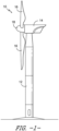
- FIG. 1 illustrates one embodiment of a wind turbine 10 according to the present disclosure.
- the wind turbine 10 includes a tower 12 with a nacelle 14 mounted thereon.
- a plurality of rotor blades 16 are mounted to a rotor hub 18, which is in turn connected to a main flange that turns a main rotor shaft.
- the wind turbine power generation and control components are housed within the nacelle 14.
- the view of FIG. 1 is provided for illustrative purposes only to place the present invention in an exemplary field of use. It should be appreciated that the invention is not limited to any particular type of wind turbine configuration.
- the present invention is not limited to use with wind turbines, but may be utilized in any application having rotor blades.
- the methods described herein may also apply to manufacturing any similar structure that benefits from printing a structure directly to skins within a mold before the skins have cooled so as to take advantage of the heat from the skins to provide adequate bonding between the printed structure and the skins. As such, the need for additional adhesive or additional curing is eliminated.
- thermoplastic rotor blade components and/or materials as described herein generally encompass a plastic material or polymer that is reversible in nature.
- thermoplastic materials typically become pliable or moldable when heated to a certain temperature and returns to a more rigid state upon cooling.
- thermoplastic materials may include amorphous thermoplastic materials and/or semi-crystalline thermoplastic materials.
- some amorphous thermoplastic materials may generally include, but are not limited to, styrenes, vinyls, cellulosics, polyesters, acrylics, polysulphones, and/or imides.
- exemplary amorphous thermoplastic materials may include polystyrene, acrylonitrile butadiene styrene (ABS), polymethyl methacrylate (PMMA), glycolised polyethylene terephthalate (PET-G), polycarbonate, polyvinyl acetate, amorphous polyamide, polyvinyl chlorides (PVC), polyvinylidene chloride, polyurethane, or any other suitable amorphous thermoplastic material.
- exemplary semi-crystalline thermoplastic materials may generally include, but are not limited to polyolefins, polyamides, fluropolymer, ethyl-methyl acrylate, polyesters, polycarbonates, and/or acetals.
- exemplary semi-crystalline thermoplastic materials may include polybutylene terephthalate (PBT), polyethylene terephthalate (PET), polypropylene, polyphenyl sulfide, polyethylene, polyamide (nylon), polyetherketone, or any other suitable semi-crystalline thermoplastic material.
- PBT polybutylene terephthalate
- PET polyethylene terephthalate
- Ppropylene polypropylene
- polyphenyl sulfide polyethylene
- polyamide nylon
- polyetherketone polyetherketone
- thermoset components and/or materials as described herein generally encompass a plastic material or polymer that is non-reversible in nature.
- thermoset materials once cured, cannot be easily remolded or returned to a liquid state.
- thermoset materials after initial forming, are generally resistant to heat, corrosion, and/or creep.
- Example thermoset materials may generally include, but are not limited to, some polyesters, some polyurethanes, esters, epoxies, or any other suitable thermoset material.
- thermoplastic and/or the thermoset material as described herein may optionally be reinforced with a fiber material, including but not limited to glass fibers, carbon fibers, polymer fibers, wood fibers, bamboo fibers, ceramic fibers, nanofibers, metal fibers, or similar or combinations thereof.
- a fiber material including but not limited to glass fibers, carbon fibers, polymer fibers, wood fibers, bamboo fibers, ceramic fibers, nanofibers, metal fibers, or similar or combinations thereof.
- the direction of the fibers may include multi-axial, unidirectional, biaxial, triaxial, or any other another suitable direction and/or combinations thereof.
- the fiber content may vary depending on the stiffness required in the corresponding blade component, the region or location of the blade component in the rotor blade 16, and/or the desired weldability of the component.
- the main blade structure 15 may include any one of or a combination of the following: a pre-formed blade root section 20, a pre-formed blade tip section 22, one or more one or more continuous spar caps 48, 50, 51, 53, one or more shear webs 35 ( FIGS. 6-7 ), an additional structural component 52 (such as an additional spar cap) secured to the blade root section 20, and/or any other suitable structural component of the rotor blade 16.
- the blade root section 20 is configured to be mounted or otherwise secured to the rotor 18 ( FIG. 1 ).
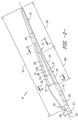
- the rotor blade 16 defines a span 23 that is equal to the total length between the blade root section 20 and the blade tip section 22. As shown in FIGS.
- the rotor blade 16 also defines a chord 25 that is equal to the total length between a leading edge 24 of the rotor blade 16 and a trailing edge 26 of the rotor blade 16. As is generally understood, the chord 25 may generally vary in length with respect to the span 23 as the rotor blade 16 extends from the blade root section 20 to the blade tip section 22.
- any number of blade segments 21 having any suitable size and/or shape may be generally arranged between the blade root section 20 and the blade tip section 22 along a longitudinal axis 27 in a generally span-wise direction.
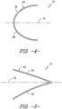
- the blade segments 21 generally serve as the outer casing/covering of the rotor blade 16 and may define a substantially aerodynamic profile that includes a pressure side surface 31 and a suction side surface 33 ( FIGS. 3 and 4 ), such as by defining a symmetrical or cambered airfoil-shaped cross-section.
- the blade segment portion of the blade 16 may include any combination of the segments described herein and are not limited to the embodiment as depicted.
- the leading edge segments 40 may have a forward pressure side surface 28 and a forward suction side surface 30.
- each of the trailing edge segments 42 may have an aft pressure side surface 32 and an aft suction side surface 34.
- the forward pressure side surface 28 of the leading edge segment 40 and the aft pressure side surface 32 of the trailing edge segment 42 generally define a pressure side surface of the rotor blade 16.
- the forward suction side surface 30 of the leading edge segment 40 and the aft suction side surface 34 of the trailing edge segment 42 generally define a suction side surface of the rotor blade 16.
- the leading edge segment(s) 40 and the trailing edge segment(s) 42 may be joined at a pressure side seam 36 and a suction side seam 38.
- the blade segments 40, 42 may be configured to overlap at the pressure side seam 36 and/or the suction side seam 38.
- adjacent blade segments 21 may be configured to overlap at a seam 54.
- adjacent blade segments 21 can be welded together along the seams 36, 38, 54, which will be discussed in more detail herein.
- the various segments of the rotor blade 16 may be secured together via an adhesive (or mechanical fasteners) configured between the overlapping leading and trailing edge segments 40, 42 and/or the overlapping adjacent leading or trailing edge segments 40, 42.
- the blade root section 20 may include one or more longitudinally extending spar caps 48, 50 infused therewith.
- the blade tip section 22 may include one or more longitudinally extending spar caps 51, 53 infused therewith.
- the spar caps 48, 50, 51, 53 may be configured to be engaged against opposing inner surfaces of the blade segments 21 of the rotor blade 16.
- the blade root spar caps 48, 50 may be configured to align with the blade tip spar caps 51, 53.
- the spar caps 48, 50, 51, 53 may generally be designed to control the bending stresses and/or other loads acting on the rotor blade 16 in a generally span-wise direction (a direction parallel to the span 23 of the rotor blade 16) during operation of a wind turbine 10.
- the spar caps 48, 50, 51, 53 may be designed to withstand the span-wise compression occurring during operation of the wind turbine 10.
- the spar cap(s) 48, 50, 51, 53 may be configured to extend from the blade root section 20 to the blade tip section 22 or a portion thereof.
- the blade root section 20 and the blade tip section 22 may be joined together via their respective spar caps 48, 50, 51, 53.
- the spar caps 48, 50, 51, 53 may be constructed of any suitable materials, e.g. a thermoplastic or thermoset material or combinations thereof. Further, the spar caps 48, 50, 51, 53 may be pultruded from thermoplastic or thermoset resins. As used herein, the terms “pultruded,” “pultrusions,” or similar generally encompass reinforced materials (e.g. fibers or woven or braided strands) that are impregnated with a resin and pulled through a stationary die such that the resin cures or undergoes polymerization. As such, the process of manufacturing pultruded members is typically characterized by a continuous process of composite materials that produces composite parts having a constant cross-section.
- reinforced materials e.g. fibers or woven or braided strands
- the present disclosure is directed to methods for joining first and second blade components the rotor blade 16 together at a joint, e.g. via 3-D printing.
- the first and second blade components may include the pressure and/or suction side surfaces 31, 33 of the rotor blade 16, the shear web 35, the spar cap 48, 50, 51, 53 and/or combinations thereof.
- the methods of the present disclosure can be used in a variety of joint areas or connections, including but not limited to a spar cap/shear web connection, a spar cap/blade shell connection, and/or a blade shell/blade shell connection.
- the blade shell/blade shell connection may include the trailing edge 26 and/or the leading edge 24 of the rotor blade 16.
- FIGS. 8-14 illustrates the process of forming first and second joint areas 68 and 72 between the pressure and/or suction side surfaces 31, 33 (i.e. at the trailing and leading edges 26, 24).
- 3-D printing is generally understood to encompass processes used to synthesize three-dimensional objects in which successive layers of material are formed under computer control to create the objects. As such, objects of almost any size and/or shape can be produced from digital model data. It should further be understood that the methods of the present disclosure are not limited to 3-D printing, but rather, may also encompass more than three degrees of freedom such that the printing techniques are not limited to printing stacked two-dimensional layers, but are also capable of printing curved shapes.
- one embodiment of the method includes placing a mold 58 of the rotor blade 16 (or one of the blade segments 21) relative to a CNC device 60. More specifically, as shown in the illustrated embodiment, the method may include placing the mold 58 into a bed 64 of the CNC device 60. Alternatively, the method may include placing the mold 58 under the CNC device 60 or adjacent the CNC device 60.
- the method of the present disclosure further includes forming one or more fiber-reinforced outer skin surfaces 56 in the mold 58 of the rotor blade 16.
- the outer skin surface(s) 56 (which form the pressure and/or suction side surfaces 31, 33) may include one or more continuous, multi-axial (e.g. biaxial) fiber-reinforced thermoplastic or thermoset outer skins.
- the method of forming the fiber-reinforced outer skin surfaces 56 may include at least one of injection molding, 3-D printing, 2-D pultrusion, 3-D pultrusion, thermoforming, vacuum forming, pressure forming, bladder forming, automated fiber deposition, automated fiber tape deposition, or vacuum infusion.
- a thermoset material may be infused into the fiber material on the mold 58 to form the outer skin surface 56 using vacuum infusion.
- the vacuum bag is removed after curing and the grid structures 66, 70 described herein can then be printed onto the inner surface of the outer skin surfaces 56.
- the vacuum bag may be left in place after curing.
- the vacuum bag material can be chosen such that the material would not easily release from the cured thermoset fiber material.
- Such materials may include a thermoplastic material such as polymethyl methacrylate (PMMA) or polycarbonate film.
- PMMA polymethyl methacrylate
- the thermoplastic film that is left in place allows for bonding of thermoplastic grid structures 66 to the thermoset skins with the film in between.
- the outer skin surface(s) 56 may be formed of a reinforced thermoplastic resin with the grid structures 66, 70 being formed of a thermoset-based resin with optional fiber reinforcement.
- the grid structures 66, 70 may be printed to the outer skin surfaces 56 while the surfaces 56 are still hot, warm, partially cooled, or completely cooled.
- the outer skin surfaces 56 may be further treated to promote bonding between the outer skin surfaces s56 and the grid structure 66, 70. More specifically, in certain embodiments, the outer skin surfaces 56 may be treated using flame treating, plasma treating, chemical treating, chemical etching, mechanical abrading, embossing, elevating a temperature of at least areas to be printed on the outer skin surfaces 56, and/or any other suitable treatment method to promote said bonding. In additional embodiments, the method may include forming the outer skin surfaces 56 with more (or even less) matrix resin material on the inside surface to promote said bonding. In additional embodiments, the method may include varying the outer skin thickness and/or fiber content, as well as the fiber orientation.
- the outer skin surface(s) 56 of the rotor blade 16 may be curved.
- the method may include forming the curvature of the outer skin surfaces 56.
- Such forming may include providing one or more generally flat fiber-reinforced outer skin surfaces, forcing the outer skin surfaces 56 into a desired shape corresponding to a desired contour, and maintaining the outer skin surfaces 56 in the desired shape during printing and depositing.
- the outer skin surfaces 56 generally retain their desired shape when the outer skin surfaces 56 and the grid structures 66, 70 printed thereto are released.
- the CNC device 60 may be adapted to include a tooling path that follows the contour of the rotor blade 16.
- one embodiment of the method includes printing and depositing the grid structure 66 directly to the inner surface of the outer skin surface(s) 56 via the CNC device 60. More specifically, as shown, the CNC device 60 is configured to print and deposit, at least, a first the grid structure 66 onto the inner surface of the first outer surface at the first joint area 68 of the rotor blade 16. In addition, as shown, the CNC device 60 may print and deposit a second grid structure 70 onto the inner surface of the first outer surface 56 at a different, second joint area 72.
- any suitable shape of grid structures 66, 70 described herein can be printed and deposited as desired.
- the grid structures 66, 70 may bond to the outer skin(s) 56 as the grid structures 66, 70 are being deposited, which reduces the amount of adhesive and/or curing time needed for the first and second joint areas 68, 72, respectively.
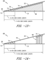
- FIGS. 13 and 14 various embodiments of different shapes and sizes of the grid structure 66 at the trailing edge 26 are illustrated. More specifically, as shown in the illustrated embodiment, the grid structure 66 may have a size ranging from about 10 millimeters (mm) to about 300 mm.
- the size of the grid structures 66, 70 may depend on the size and shape of the rotor blade 16. Further, as shown in FIG. 13 , the grid structure 66 may extend from the adhesive 74 at the trailing edge 26 up to, e.g. 30% chord length. Alternatively, as shown in FIG. 14 , the grid structure 66 may be spaced apart from the adhesive 74 at the trailing edge 26 so as to minimize the weight at the joint area 68.
- the CNC device 60 is configured to print and deposit the grid structures 66, 70 after the formed skin surface 56 reaches a desired state that enables bonding of the grid structures 66, 70 thereto, i.e. based on one or more parameters of temperature, time, and/or hardness. Therefore, in certain embodiments, wherein the skin surfaces 56 and grid structures 66, 70 are formed of a thermoplastic matrix, the CNC device 60 may immediately print the grid structures 66, 70 thereto as the forming temperature of the skin surface(s) 56 and the desired printing temperature to enable thermoplastic welding/bonding can be the same).
- the CNC device 60 before the skin surface(s) 56 have cooled from forming, (i.e. while the skins are still hot or warm), the CNC device 60 is configured to print and deposit the grid structures 66, 70 onto the inner surface of the outer skin surfaces 56.
- the CNC device 60 is configured to print and deposit the grid structures 66, 70 onto the inner surface of the outer skin surfaces 56 before the surfaces 56 have completely cooled.
- the CNC device 60 is configured to print and deposit the grid structures 66, 70 onto the inner surface of the outer skin surfaces 56 when the surfaces 56 have partially cooled.
- suitable materials for the grid structures 66, 70 and the outer skin surfaces 56 can be chosen such that the grid structures 66, 70 bonds to the outer skin surfaces 56 during deposition. Accordingly, the grid structures 66, 70 described herein may be printed using the same materials or different materials.
- the grid structures 66, 70 of the present disclosure may include varying shapes and/or designs (e.g. materials, width, height, thickness, shapes, etc., or combinations thereof).
- the grid structures 66, 70 may define any suitable shape so as to form any suitable structure that can be used at any joint connection within the rotor blade 16 such that adhesives can be reduced in such joints.
- the CNC device 60 can be designed having one or more extruders 62 that generate any suitable thickness or width so as to disperse a desired amount of resin material to create the grid structures 66, 70 with varying heights and/or thicknesses.
- many rotor blade joints include tight angles and/or tapered cross-sections that are conventionally filled with adhesives.
- the grid structure(s) 66, 70 of the present disclosure can be printed to contact both of the inner surfaces of the pressure and/or suction side surfaces 31, 33.
- the grid structure(s) 66, 70 may include a tapered chord-wise cross-section.
- the CNC device 60 may also print and deposit one or more alignment structures 82 into the grid structure(s) 66, 70.
- the grid structure(s) 66, 70 may include may include an alignment structure 82 that is printed along with the grid structure(s) 66, 70 for assisting in aligning adjacent rotor blade components (such as printed reinforcement grids of the pressure and/or suction side surfaces 31, 33).
- the structures 66, 70 can retain heat as the printed structure gets taller. Additional heat can be further retained as the shape of many rotor blade joints are tapered or angled, thereby requiring grid structures 66, 70 within a tapered or angled cross-section. As such, the printed layer times get shorter as the part is built. As a result, taller structures and those portions with shorter layer times (i.e. the time it takes to print a layer before starting the next layer) can begin to sag and puddle as there is not enough cooling time to sufficiently solidify the previous layer.
- the method of the present disclosure is configured to slow down the print speeds as needed, alter the formulation of the resin system to use a faster solidifying resin matrix (e.g. a more semi crystalline/less amorphous formulation), and/or selectively apply cooling air to the grid structures 66, 70 during printing and depositing.
- a faster solidifying resin matrix e.g. a more semi crystalline/less amorphous formulation
- the CNC device 60 may include one or more cooling fans 82 or cooling air nozzles that selectively turn on as needed to cool down the grid structures 66, 70.
- the method may include providing an adhesive 74 at the first joint area 68 and/or the second joint area 72, e.g. to at least partially fill the grid structures 66, 70.
- the method also includes placing the second outer surface atop the first outer surface and the printed grid structures 66, 70 and securing the first and second outer skin surfaces 31, 33 together at first and second joints 73, 75, respectively, via the adhesive 74.
- the first joint 73 contains the trailing edge 26 of the rotor blade 16, where the pressure and suction side surfaces 31, 33 of the rotor blade 16 are secured together.
- the second joint 75 contains the leading edge 24 of the rotor blade 16, also where the pressure and suction side surfaces 31, 33 of the rotor blade 16 are secured together.
- the first grid structure 66 may be spaced apart from the trailing edge 26 of the rotor blade 16 to provide a first gap 76. More specifically, as shown in FIGS. 13 and 14 , the first gap 76 may extend from about 1% to about 20% as an example of the chord-wise length of the rotor blade 16. It should be understood that the first gap 76 may include any suitable chord-wise length that is sufficient for adhesion of the pressure and suction side surfaces 31, 33.
- the second grid structure 70 may also be spaced apart from the leading edge 24 of the rotor blade 16 to provide a second gap 78.
- the second gap 78 may extend from about 1% to about 20% as an example of the chord-wise length of the rotor blade 16. Further, it should be understood that the second gap 78 may include any suitable chord-wise length that is sufficient for adhesion of the pressure and suction side surfaces 31, 33.
- the method may also include filling, at least in part, the first and/or second gaps 76, 78 with the adhesive 74.
- the first gap 76 may be completely filled with adhesive 74.
- the second gap 78 may be left primarily free of adhesive 74.
- the second gap 78 may be partially or completely filled with adhesive 74.
- the method may include forming at least a portion of the grid structure 62 of a foaming agent 80.
- a portion of the grid structure 66 at the first joint area 68 is formed of the foaming agent 80 to further reduce the weight of the structure 62 and therefore the overall rotor blade 16.
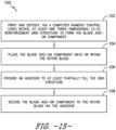
- FIG. 15 a flow diagram of one embodiment of a method 100 for securing a blade add-on component to a rotor blade 16 is illustrated.
- the method 100 includes printing and depositing, via the CNC device 60, at least one three-dimensional (3-D) grid structure to form the blade add-on component.
- the method 100 includes placing the blade add-on component onto or within the rotor blade.
- the method 100 includes providing an adhesive to at least partially fill the grid structure.
- the method 100 includes securing the blade add-on component to the rotor blade via the adhesive.
- blade add-on component may include flatback airfoil corner sections, tip extensions (i.e. a grid structure used to fill thin sections between a sock tip and the rotor blade 16, and allow for bonding using this grid technique), or a reinforcement structure for a leading edge or a trailing edge.
- tip extensions i.e. a grid structure used to fill thin sections between a sock tip and the rotor blade 16, and allow for bonding using this grid technique
- a reinforcement structure for a leading edge or a trailing edge may be included in the blade add-on component.
Landscapes
- Engineering & Computer Science (AREA)
- Mechanical Engineering (AREA)
- Chemical & Material Sciences (AREA)
- Sustainable Development (AREA)
- General Engineering & Computer Science (AREA)
- Combustion & Propulsion (AREA)
- Sustainable Energy (AREA)
- Life Sciences & Earth Sciences (AREA)
- Physics & Mathematics (AREA)
- Composite Materials (AREA)
- Human Computer Interaction (AREA)
- Automation & Control Theory (AREA)
- General Physics & Mathematics (AREA)
- Manufacturing & Machinery (AREA)
- Fluid Mechanics (AREA)
- Wind Motors (AREA)
Description
- The present disclosure relates in general to wind turbine rotor blades, and more particularly to methods for joining blade components of rotor blades using printed grid structures.
- Wind power is considered one of the cleanest, most environmentally friendly energy sources presently available, and wind turbines have gained increased attention in this regard. A modern wind turbine typically includes a tower, a generator, a gearbox, a nacelle, and one or more rotor blades. The rotor blades capture kinetic energy of wind using known foil principles. The rotor blades transmit the kinetic energy in the form of rotational energy so as to turn a shaft coupling the rotor blades to a gearbox, or if a gearbox is not used, directly to the generator. The generator then converts the mechanical energy to electrical energy that may be deployed to a utility grid.
- The rotor blades generally include a suction side shell and a pressure side shell typically formed using molding processes that are bonded together at bond lines along the leading and trailing edges of the blade. Further, the pressure and suction shells are relatively lightweight and have structural properties (e.g., stiffness, buckling resistance and strength) which are not configured to withstand the bending moments and other loads exerted on the rotor blade during operation. Thus, to increase the stiffness, buckling resistance and strength of the rotor blade, the body shell is typically reinforced using one or more structural components (e.g. opposing spar caps with a shear web configured therebetween) that engage the inner pressure and suction side surfaces of the shell halves.
- In addition, conventional rotor blades require a substantial amount of bond paste to provide structure at various blade joints (e.g. at the leading or trailing edges of the rotor blade) to prevent local buckling of the suction and pressure side shells. Due to the complex geometry near these joint areas, it is often difficult to provide this structure in other ways that would be lighter than bond paste. Thus, conventional rotor blades typically utilize excess paste for the structure needed at the joints. Such excess paste, however, is expensive, heavy, and can limit the types of adhesives that can be used. For example, heavy and thick adhesive sections containing fast curing adhesives with high exothermic reactions can generate excess heat and damage the surrounding materials, thereby creating safety hazards.
- In view of the foregoing, the art is continually seeking improved methods for joining blade components of rotor blades that use less adhesives.
-
US 2017/204833 A1 discloses a method of manufacturing a rotor blade for a wind turbine. The method includes providing a blade mold of the rotor blade, placing an outer skin layer in the blade mold, placing one or more structural inserts in the blade mold atop the outer skin layer as a function of a load of the rotor blade and placing an inner skin layer atop the one or more structural inserts and securing the outer skin layer, the one or more structural inserts, and the inner skin layer together to form the rotor blade. -
US 2009/155084 A1 discloses method and system for assembling large wind turbine blades that includes providing a plurality of wind turbine blade segments. An adhesive distribution arrangement is disposed on a surface of at least one of the plurality of the wind turbine blade segments. The adhesive distribution arrangement includes a bonding grid having a plurality of adhesive distribution openings. The wind turbine blade segments are directed together and sufficient adhesive is provided to the bonding grid to substantially fill an area between the wind turbine segments. The adhesive is then cured to form a bonded joint, the bonding grid being incorporated into the bonded joint. A bonding grid for use with the method and system and a segmented wind turbine blade are also disclosed. -
US 4 474 536 A1 discloses a hollow wind turbine blades and the like comprising abutting blade sections, with nose forming strips and converging walls forming a tail section connecting with the ends of the nose forming strips, and a method of fabricating them comprising machining the facial end walls of the abutting blade sections to provide a precise alignment thereof providing a flush joint when the sections are butted together, adhesively bonding the blade sections in abutting relation and permitting the bond to cure, cutting communicating splice receiving slots in the abutting nose forming strips, and inserting adhesively bonding splice inserts which fit the slots in place in the slot. -
US 2017/145990 A1 discloses a wind turbine blade with a trailing edge including a radially inboard portion and a radially outboard portion opposite the radially inboard portion. The trailing edge further includes at least one serrated portion extending at least partially between the radially inboard portion and the radially outboard portion. The serrated portion includes at least one substantially acoustically absorbent material. -
EP 3 050 651 A1 - Other examples of the prior art for a joint area of a rotor blade of a wind turbine and a method for joining a first blade component and a second blade component of a rotor blade are described in
US 2013/0108455 andWO 2017/220740 . - Aspects and advantages of the invention will be set forth in part in the following description, or may be obvious from the description, or may be learned through practice of the invention.
- In one aspect as defined in
claim 1, the present disclosure is directed to a method for joining a first blade component and a second blade component of a rotor blade together. The method includes printing and depositing, via a computer numeric control (CNC) device, at least one three-dimensional (3-D) grid structure at a first joint area of the rotor blade. The first joint area contains the first blade component interfacing with the second blade component. The method also includes providing an adhesive at the first joint area and contacting at least a portion of the grid structure. Further, the method includes securing the first blade component and the second blade component together at the first joint area via the adhesive. - In one embodiment, the adhesive may at least partially fill the grid structure. In another embodiment, the first and second blade components may include first and second outer surfaces of the rotor blade, a shear web, and/or a spar cap. Thus, in one embodiment, the method may include placing the first outer surface into a mold of the rotor blade, printing and depositing, via the CNC device, the grid structure(s) onto an inner surface of the first outer surface at the first joint area, wherein the grid structure bonds to the first outer surface as the grid structure is being deposited, placing the second outer surface atop the first outer surface, and securing the first and second outer surfaces together via the adhesive.
- According to the invention, the first joint area includes a spar cap/shear web connection, a spar cap/blade shell connection, and/or a blade shell/blade shell connection. More specifically, in certain embodiments, the blade shell/blade shell connection includes a trailing edge and/or a leading edge of the rotor blade.
- According to the invention, the method includes printing and depositing, via the CNC device, a first grid structure onto the inner surface of the first outer surface at the first joint area and a second grid structure onto the inner surface of the first outer surface at a different, second joint area. In such embodiments, the method also includes printing and depositing, via the CNC device, the first grid structure onto the inner surface of the first outer surface and spaced apart from the trailing edge of the rotor blade to provide a first gap. In addition, the method further includes printing and depositing, via the CNC device, the second grid structure onto the inner surface of the first outer surface and spaced apart from the leading edge of the rotor blade to provide a second gap.
- According to the invention, the method includes filling, at least in part, at least one of the first gap or the second gap with the adhesive. In addition to the adhesive, in certain embodiments, the method may also include forming at least a portion of the grid structure of a foaming agent.
- In still further embodiments, the method may include selectively applying cooling air to the grid structure during printing and depositing. In yet another embodiment, the method may also include printing and depositing, via the CNC device, one or more alignment structures into the at least one grid structure.
- In additional embodiments, the grid structure(s) may contact the inner surface of the first outer surface and an inner surface of the second outer surface. Thus, in certain embodiments, the grid structure(s) may include a tapered chord-wise cross-section.
- In another aspect according to
claim 9, the present disclosure is directed to a joint area of a rotor blade of a wind turbine. The joint area includes a first blade component, a second blade component interfacing with the first blade component at a joint, at least one three-dimensional (3-D) grid structure positioned between the first and second blade components adjacent to the joint, and an adhesive provided between the grid structure and the first and second blade components. - In one embodiment, the first and second blade components of the joint area may include first and second outer surfaces of the rotor blade, a shear web, or a spar cap. In another embodiment, the grid structure(s) may be formed, at least in part, via additive manufacturing. Alternatively, or in addition, the grid structure(s) may be formed, at least in part, of a pre-fabricated honeycomb material. It should be understood that the joint area may further include any of the additional features as described herein.
- In yet another non-claimed aspect, the present disclosure is directed to a method for securing a blade add-on component to a rotor blade. The method includes printing and depositing, via a computer numeric control (CNC) device, at least one three-dimensional (3-D) grid structure to form the blade add-on component. The method also includes placing the blade add-on component onto or within the rotor blade. Further, the method includes providing an adhesive to at least partially fill the grid structure. Moreover, the method includes securing the blade add-on component to the rotor blade via the adhesive.
- In one embodiment, the blade add-on component may correspond to a reinforcement structure for a leading edge or a trailing edge, a flatback airfoil corner, or a tip extension. It should be understood that the method may further include any of the additional features and/or steps as described herein.
- These and other features, aspects and advantages of the present invention will become better understood with reference to the following description and appended claims. The accompanying drawings, which are incorporated in and constitute a part of this specification, illustrate embodiments of the invention and, together with the description, serve to explain the principles of the invention.
- A full and enabling disclosure of the present invention, including the best mode thereof, directed to one of ordinary skill in the art, is set forth in the specification, which makes reference to the appended figures, in which:
-
FIG. 1 illustrates a perspective view of one embodiment of a wind turbine according to the present disclosure; -
FIG. 2 illustrates a perspective view of one embodiment of a rotor blade of a wind turbine according to the present disclosure; -
FIG. 3 illustrates an exploded view of the modular rotor blade ofFIG. 2 ; -
FIG. 4 illustrates a cross-sectional view of one embodiment of a leading edge segment of a modular rotor blade according to the present disclosure; -
FIG. 5 illustrates a cross-sectional view of one embodiment of a trailing edge segment of a modular rotor blade according to the present disclosure; -
FIG. 6 illustrates a cross-sectional view of the modular rotor blade ofFIG. 2 according to the present disclosure; -
FIG. 7 illustrates a cross-sectional view of the modular rotor blade ofFIG. 2 according to the present disclosure; -
FIG. 8 illustrates a side, perspective view of one embodiment of a mold of a rotor blade placed within a bed of a three-dimensional printer, particularly illustrating an outer skin surface placed in the mold according to the present disclosure; -
FIG. 9 illustrates a side, perspective view of one embodiment of a mold of a rotor blade placed within a bed of a three-dimensional printer, particularly illustrating an outer skin surface placed in the mold with a plurality of grid structures printed thereto according to the present disclosure; -
FIG. 10 illustrates a cross-sectional view of one embodiment of a rotor blade having a plurality of grid structures printed at different joint areas of the rotor blade according to the present disclosure; -
FIG. 11 illustrates a detailed, cross-sectional view of the rotor blade ofFIG. 10 at the trailing edge joint; -
FIG. 12 illustrates a detailed, cross-sectional view of the rotor blade ofFIG. 10 at the leading edge joint; -
FIG. 13 illustrates a detailed, cross-sectional view of one embodiment of trailing edge joint area of a rotor blade containing a printed grid structure according to the present disclosure; -
FIG. 14 illustrates a detailed, cross-sectional view of another embodiment of trailing edge joint area of a rotor blade containing a printed grid structure according to the present disclosure; and -
FIG. 15 illustrates a flow diagram of one embodiment of a method for securing a blade add-on component to a rotor blade according to the present disclosure. - Reference now will be made in detail to embodiments of the invention, one or more examples of which are illustrated in the drawings. Each example is provided by way of explanation of the invention, not limitation of the invention. In fact, it will be apparent to those skilled in the art that various modifications and variations can be made in the present invention without departing from the scope of the invention. For instance, features illustrated or described as part of one embodiment can be used with another embodiment to yield a still further embodiment. Thus, it is intended that the present invention covers such modifications and variations as come within the scope of the appended claims.
- Generally, the present disclosure is directed to methods for manufacturing grid structures for wind turbine rotor blades using automated deposition of materials via technologies such as 3-D Printing, additive manufacturing, automated fiber deposition, as well as other techniques that utilize CNC control and multiple degrees of freedom to deposit material. As such, the grid structures of the present disclosure are useful for reinforcing a joint area of the rotor blade (i.e. by providing buckling resistance at the joint area). More specifically, the printed structures described herein may contain one or more gaps and may be shaped to fill the space between two laminate surfaces that require bonding. The tight gaps within the printed structure allow for a significantly reduced amount of adhesive to be used and allow the adhesive to flow between the gaps of the printed structure upon closing. Thus, the adhesive flow between the gaps and the reduced amount of adhesive needed substantially reduces the hydraulic pressure needed to close the joint. In addition, the adhesive can form a mechanical lock when cured into the structure to increase bonding strength and reliability compared to an adhesive-only bond. As such, joints of the present disclosure provide a net weight savings as the bulk of the printed structure gaps remains unfilled after closing of the joint.
- In addition, the grid structures described herein allow for faster curing adhesives to be used and reduce the overall process cycle time and weight. Moreover, the grid structures of the present disclosure allow for non-destructive testing (NDT) inspection, as the joint areas no longer require foam. Further, the grid structures of the present disclosure can be directly printed to thermoplastic fiberglass skins, thereby providing a more ideal bonding surface. The printed structures of the present disclosure may also simultaneously be used to align components during the bonding process and can be used to fill difficult gaps, such as the space created when using flat pultrusions in spar caps against a curved airfoil surface.
- Referring now to the drawings,
FIG. 1 illustrates one embodiment of awind turbine 10 according to the present disclosure. As shown, thewind turbine 10 includes atower 12 with anacelle 14 mounted thereon. A plurality ofrotor blades 16 are mounted to arotor hub 18, which is in turn connected to a main flange that turns a main rotor shaft. The wind turbine power generation and control components are housed within thenacelle 14. The view ofFIG. 1 is provided for illustrative purposes only to place the present invention in an exemplary field of use. It should be appreciated that the invention is not limited to any particular type of wind turbine configuration. In addition, the present invention is not limited to use with wind turbines, but may be utilized in any application having rotor blades. Further, the methods described herein may also apply to manufacturing any similar structure that benefits from printing a structure directly to skins within a mold before the skins have cooled so as to take advantage of the heat from the skins to provide adequate bonding between the printed structure and the skins. As such, the need for additional adhesive or additional curing is eliminated. - Referring now to
FIGS. 2 and3 , various views of arotor blade 16 according to the present disclosure are illustrated. As shown, the illustratedrotor blade 16 has a segmented or modular configuration. It should also be understood that therotor blade 16 may include any other suitable configuration now known or later developed in the art. As shown, themodular rotor blade 16 includes amain blade structure 15 constructed, at least in part, from a thermoset and/or a thermoplastic material and at least oneblade segment 21 configured with themain blade structure 15. More specifically, as shown, therotor blade 16 includes a plurality ofblade segments 21. The blade segment(s) 21 may also be constructed, at least in part, from a thermoset and/or a thermoplastic material. - The thermoplastic rotor blade components and/or materials as described herein generally encompass a plastic material or polymer that is reversible in nature. For example, thermoplastic materials typically become pliable or moldable when heated to a certain temperature and returns to a more rigid state upon cooling. Further, thermoplastic materials may include amorphous thermoplastic materials and/or semi-crystalline thermoplastic materials. For example, some amorphous thermoplastic materials may generally include, but are not limited to, styrenes, vinyls, cellulosics, polyesters, acrylics, polysulphones, and/or imides. More specifically, exemplary amorphous thermoplastic materials may include polystyrene, acrylonitrile butadiene styrene (ABS), polymethyl methacrylate (PMMA), glycolised polyethylene terephthalate (PET-G), polycarbonate, polyvinyl acetate, amorphous polyamide, polyvinyl chlorides (PVC), polyvinylidene chloride, polyurethane, or any other suitable amorphous thermoplastic material. In addition, exemplary semi-crystalline thermoplastic materials may generally include, but are not limited to polyolefins, polyamides, fluropolymer, ethyl-methyl acrylate, polyesters, polycarbonates, and/or acetals. More specifically, exemplary semi-crystalline thermoplastic materials may include polybutylene terephthalate (PBT), polyethylene terephthalate (PET), polypropylene, polyphenyl sulfide, polyethylene, polyamide (nylon), polyetherketone, or any other suitable semi-crystalline thermoplastic material.
- Further, the thermoset components and/or materials as described herein generally encompass a plastic material or polymer that is non-reversible in nature. For example, thermoset materials, once cured, cannot be easily remolded or returned to a liquid state. As such, after initial forming, thermoset materials are generally resistant to heat, corrosion, and/or creep. Example thermoset materials may generally include, but are not limited to, some polyesters, some polyurethanes, esters, epoxies, or any other suitable thermoset material.
- In addition, as mentioned, the thermoplastic and/or the thermoset material as described herein may optionally be reinforced with a fiber material, including but not limited to glass fibers, carbon fibers, polymer fibers, wood fibers, bamboo fibers, ceramic fibers, nanofibers, metal fibers, or similar or combinations thereof. In addition, the direction of the fibers may include multi-axial, unidirectional, biaxial, triaxial, or any other another suitable direction and/or combinations thereof. Further, the fiber content may vary depending on the stiffness required in the corresponding blade component, the region or location of the blade component in the
rotor blade 16, and/or the desired weldability of the component. - More specifically, as shown, the
main blade structure 15 may include any one of or a combination of the following: a pre-formedblade root section 20, a pre-formedblade tip section 22, one or more one or more continuous spar caps 48, 50, 51, 53, one or more shear webs 35 (FIGS. 6-7 ), an additional structural component 52 (such as an additional spar cap) secured to theblade root section 20, and/or any other suitable structural component of therotor blade 16. Further, theblade root section 20 is configured to be mounted or otherwise secured to the rotor 18 (FIG. 1 ). In addition, as shown inFIG. 2 , therotor blade 16 defines aspan 23 that is equal to the total length between theblade root section 20 and theblade tip section 22. As shown inFIGS. 2 and6 , therotor blade 16 also defines achord 25 that is equal to the total length between aleading edge 24 of therotor blade 16 and a trailingedge 26 of therotor blade 16. As is generally understood, thechord 25 may generally vary in length with respect to thespan 23 as therotor blade 16 extends from theblade root section 20 to theblade tip section 22. - Referring particularly to
FIGS. 2-4 , any number ofblade segments 21 having any suitable size and/or shape may be generally arranged between theblade root section 20 and theblade tip section 22 along alongitudinal axis 27 in a generally span-wise direction. Thus, theblade segments 21 generally serve as the outer casing/covering of therotor blade 16 and may define a substantially aerodynamic profile that includes apressure side surface 31 and a suction side surface 33 (FIGS. 3 and4 ), such as by defining a symmetrical or cambered airfoil-shaped cross-section. In additional embodiments, it should be understood that the blade segment portion of theblade 16 may include any combination of the segments described herein and are not limited to the embodiment as depicted. In addition, theblade segments 21 may be constructed of any suitable materials, including but not limited to a thermoset material or a thermoplastic material optionally reinforced with one or more fiber materials. More specifically, in certain embodiments, theblade segments 21 may include pressure and/orsuction side segments 44, 46 (FIGS. 2 and3 ) and/or leading and/or trailingedge segments 40, 42 (FIGS. 2-6 ), or similar. - More specifically, as shown in
FIG. 4 , the leadingedge segments 40 may have a forwardpressure side surface 28 and a forwardsuction side surface 30. Similarly, as shown inFIG. 5 , each of the trailingedge segments 42 may have an aftpressure side surface 32 and an aftsuction side surface 34. Thus, the forwardpressure side surface 28 of theleading edge segment 40 and the aftpressure side surface 32 of the trailingedge segment 42 generally define a pressure side surface of therotor blade 16. Similarly, the forwardsuction side surface 30 of theleading edge segment 40 and the aftsuction side surface 34 of the trailingedge segment 42 generally define a suction side surface of therotor blade 16. In addition, as particularly shown inFIG. 6 , the leading edge segment(s) 40 and the trailing edge segment(s) 42 may be joined at apressure side seam 36 and asuction side seam 38. For example, theblade segments pressure side seam 36 and/or thesuction side seam 38. Further, as shown inFIG. 2 ,adjacent blade segments 21 may be configured to overlap at aseam 54. Thus, where theblade segments 21 are constructed at least partially of a thermoplastic material,adjacent blade segments 21 can be welded together along theseams rotor blade 16 may be secured together via an adhesive (or mechanical fasteners) configured between the overlapping leading and trailingedge segments edge segments - In specific embodiments, as shown in
FIGS. 2-3 and6-7 , theblade root section 20 may include one or more longitudinally extending spar caps 48, 50 infused therewith. Similarly, theblade tip section 22 may include one or more longitudinally extending spar caps 51, 53 infused therewith. More specifically, as shown, the spar caps 48, 50, 51, 53 may be configured to be engaged against opposing inner surfaces of theblade segments 21 of therotor blade 16. Further, the blade root spar caps 48, 50 may be configured to align with the blade tip spar caps 51, 53. Thus, the spar caps 48, 50, 51, 53 may generally be designed to control the bending stresses and/or other loads acting on therotor blade 16 in a generally span-wise direction (a direction parallel to thespan 23 of the rotor blade 16) during operation of awind turbine 10. In addition, the spar caps 48, 50, 51, 53 may be designed to withstand the span-wise compression occurring during operation of thewind turbine 10. Further, the spar cap(s) 48, 50, 51, 53 may be configured to extend from theblade root section 20 to theblade tip section 22 or a portion thereof. Thus, in certain embodiments, theblade root section 20 and theblade tip section 22 may be joined together via their respective spar caps 48, 50, 51, 53. - In addition, the spar caps 48, 50, 51, 53 may be constructed of any suitable materials, e.g. a thermoplastic or thermoset material or combinations thereof. Further, the spar caps 48, 50, 51, 53 may be pultruded from thermoplastic or thermoset resins. As used herein, the terms "pultruded," "pultrusions," or similar generally encompass reinforced materials (e.g. fibers or woven or braided strands) that are impregnated with a resin and pulled through a stationary die such that the resin cures or undergoes polymerization. As such, the process of manufacturing pultruded members is typically characterized by a continuous process of composite materials that produces composite parts having a constant cross-section. Thus, the pre-cured composite materials may include pultrusions constructed of reinforced thermoset or thermoplastic materials. Further, the spar caps 48, 50, 51, 53 may be formed of the same pre-cured composites or different pre-cured composites. In addition, the pultruded components may be produced from rovings, which generally encompass long and narrow bundles of fibers that are not combined until joined by a cured resin.
- Referring to
FIGS. 6-7 , one ormore shear webs 35 may be configured between the one or more spar caps 48, 50, 51, 53. More particularly, the shear web(s) 35 may be configured to increase the rigidity in theblade root section 20 and/or theblade tip section 22. Further, the shear web(s) 35 may be configured to close out theblade root section 20. - Referring now to
FIGS. 8-14 , the present disclosure is directed to methods for joining first and second blade components therotor blade 16 together at a joint, e.g. via 3-D printing. For example, in one embodiment, the first and second blade components may include the pressure and/or suction side surfaces 31, 33 of therotor blade 16, theshear web 35, thespar cap edge 26 and/or the leadingedge 24 of therotor blade 16. Thus, the illustrated embodiment ofFIGS. 8-14 illustrates the process of forming first and secondjoint areas edges 26, 24). - As used herein, 3-D printing is generally understood to encompass processes used to synthesize three-dimensional objects in which successive layers of material are formed under computer control to create the objects. As such, objects of almost any size and/or shape can be produced from digital model data. It should further be understood that the methods of the present disclosure are not limited to 3-D printing, but rather, may also encompass more than three degrees of freedom such that the printing techniques are not limited to printing stacked two-dimensional layers, but are also capable of printing curved shapes.
- Referring particularly to
FIG. 8 , one embodiment of the method includes placing amold 58 of the rotor blade 16 (or one of the blade segments 21) relative to aCNC device 60. More specifically, as shown in the illustrated embodiment, the method may include placing themold 58 into abed 64 of theCNC device 60. Alternatively, the method may include placing themold 58 under theCNC device 60 or adjacent theCNC device 60. - Further, as shown, the method of the present disclosure further includes forming one or more fiber-reinforced outer skin surfaces 56 in the
mold 58 of therotor blade 16. In certain embodiments, the outer skin surface(s) 56 (which form the pressure and/or suction side surfaces 31, 33) may include one or more continuous, multi-axial (e.g. biaxial) fiber-reinforced thermoplastic or thermoset outer skins. Further, in particular embodiments, the method of forming the fiber-reinforced outer skin surfaces 56 may include at least one of injection molding, 3-D printing, 2-D pultrusion, 3-D pultrusion, thermoforming, vacuum forming, pressure forming, bladder forming, automated fiber deposition, automated fiber tape deposition, or vacuum infusion. - For example, in one embodiment, a thermoset material may be infused into the fiber material on the
mold 58 to form theouter skin surface 56 using vacuum infusion. As such, the vacuum bag is removed after curing and thegrid structures thermoplastic grid structures 66 to the thermoset skins with the film in between. - In still further embodiments, the outer skin surface(s) 56 may be formed of a reinforced thermoplastic resin with the
grid structures grid structures surfaces 56 are still hot, warm, partially cooled, or completely cooled. - In addition, the outer skin surfaces 56 may be further treated to promote bonding between the outer skin surfaces s56 and the
grid structure - In addition, as shown, the outer skin surface(s) 56 of the
rotor blade 16 may be curved. In such embodiments, the method may include forming the curvature of the outer skin surfaces 56. Such forming may include providing one or more generally flat fiber-reinforced outer skin surfaces, forcing the outer skin surfaces 56 into a desired shape corresponding to a desired contour, and maintaining the outer skin surfaces 56 in the desired shape during printing and depositing. As such, the outer skin surfaces 56 generally retain their desired shape when the outer skin surfaces 56 and thegrid structures CNC device 60 may be adapted to include a tooling path that follows the contour of therotor blade 16. - Thus, as shown in
FIG. 9 , one embodiment of the method includes printing and depositing thegrid structure 66 directly to the inner surface of the outer skin surface(s) 56 via theCNC device 60. More specifically, as shown, theCNC device 60 is configured to print and deposit, at least, a first thegrid structure 66 onto the inner surface of the first outer surface at the firstjoint area 68 of therotor blade 16. In addition, as shown, theCNC device 60 may print and deposit asecond grid structure 70 onto the inner surface of the firstouter surface 56 at a different, secondjoint area 72. - It should be understood that any suitable shape of
grid structures grid structures grid structures joint areas FIGS. 13 and 14 , various embodiments of different shapes and sizes of thegrid structure 66 at the trailingedge 26 are illustrated. More specifically, as shown in the illustrated embodiment, thegrid structure 66 may have a size ranging from about 10 millimeters (mm) to about 300 mm. It should be understood, however, that the size of thegrid structures rotor blade 16. Further, as shown inFIG. 13 , thegrid structure 66 may extend from the adhesive 74 at the trailingedge 26 up to, e.g. 30% chord length. Alternatively, as shown inFIG. 14 , thegrid structure 66 may be spaced apart from the adhesive 74 at the trailingedge 26 so as to minimize the weight at thejoint area 68. - For example, in one embodiment, the
CNC device 60 is configured to print and deposit thegrid structures skin surface 56 reaches a desired state that enables bonding of thegrid structures grid structures CNC device 60 may immediately print thegrid structures - More specifically, in particular embodiments, before the skin surface(s) 56 have cooled from forming, (i.e. while the skins are still hot or warm), the
CNC device 60 is configured to print and deposit thegrid structures CNC device 60 is configured to print and deposit thegrid structures surfaces 56 have completely cooled. In addition, in another embodiment, theCNC device 60 is configured to print and deposit thegrid structures surfaces 56 have partially cooled. Thus, suitable materials for thegrid structures grid structures grid structures - It should be understood that the
grid structures grid structures rotor blade 16 such that adhesives can be reduced in such joints. Thus, theCNC device 60 can be designed having one ormore extruders 62 that generate any suitable thickness or width so as to disperse a desired amount of resin material to create thegrid structures FIG. 10 , the grid structure(s) 66, 70 of the present disclosure can be printed to contact both of the inner surfaces of the pressure and/or suction side surfaces 31, 33. Thus, in such embodiments, the grid structure(s) 66, 70 may include a tapered chord-wise cross-section. - In yet another embodiment, the
CNC device 60 may also print and deposit one ormore alignment structures 82 into the grid structure(s) 66, 70. For example, as shown inFIGS. 11 and 12 , the grid structure(s) 66, 70 may include may include analignment structure 82 that is printed along with the grid structure(s) 66, 70 for assisting in aligning adjacent rotor blade components (such as printed reinforcement grids of the pressure and/or suction side surfaces 31, 33). - When the
grid structures structures grid structures grid structures FIG. 9 , theCNC device 60 may include one or more coolingfans 82 or cooling air nozzles that selectively turn on as needed to cool down thegrid structures - In addition to additive manufacturing, the
grid structures - After the
grid structures outer skin surface 56, as shown inFIGS. 10-14 , the method may include providing an adhesive 74 at the firstjoint area 68 and/or the secondjoint area 72, e.g. to at least partially fill thegrid structures grid structures second joints FIG. 10 , the first joint 73 contains the trailingedge 26 of therotor blade 16, where the pressure and suction side surfaces 31, 33 of therotor blade 16 are secured together. Similarly, as shown, the second joint 75 contains the leadingedge 24 of therotor blade 16, also where the pressure and suction side surfaces 31, 33 of therotor blade 16 are secured together. - In such embodiments, as shown in
FIGS. 11 ,13, and 14 , thefirst grid structure 66 may be spaced apart from the trailingedge 26 of therotor blade 16 to provide afirst gap 76. More specifically, as shown inFIGS. 13 and 14 , thefirst gap 76 may extend from about 1% to about 20% as an example of the chord-wise length of therotor blade 16. It should be understood that thefirst gap 76 may include any suitable chord-wise length that is sufficient for adhesion of the pressure and suction side surfaces 31, 33. In addition, as shown inFIG. 12 , thesecond grid structure 70 may also be spaced apart from the leadingedge 24 of therotor blade 16 to provide asecond gap 78. Similarly, thesecond gap 78 may extend from about 1% to about 20% as an example of the chord-wise length of therotor blade 16. Further, it should be understood that thesecond gap 78 may include any suitable chord-wise length that is sufficient for adhesion of the pressure and suction side surfaces 31, 33. - Thus, the method may also include filling, at least in part, the first and/or
second gaps FIGS. 10 and11 , thefirst gap 76 may be completely filled with adhesive 74. Alternatively, as shown inFIG. 13 , only a portion of thefirst gap 76 may be filled with adhesive 74. In addition, as shown inFIGS. 10 and12 , thesecond gap 78 may be left primarily free of adhesive 74. Alternatively, thesecond gap 78 may be partially or completely filled with adhesive 74. - In another embodiment, the method may include forming at least a portion of the
grid structure 62 of afoaming agent 80. For example, as shown inFIG. 11 , a portion of thegrid structure 66 at the firstjoint area 68 is formed of the foamingagent 80 to further reduce the weight of thestructure 62 and therefore theoverall rotor blade 16. - The methods of the present disclosure can also be useful for certain types of blade add-on components, where certain aerodynamic features are desired to be added to the exterior surface of a rotor blade either after production and/or to existing rotor blades in the field. Thus, referring now to
FIG. 15 , a flow diagram of one embodiment of a method 100 for securing a blade add-on component to arotor blade 16 is illustrated. As shown at 102, the method 100 includes printing and depositing, via theCNC device 60, at least one three-dimensional (3-D) grid structure to form the blade add-on component. As shown at 104, the method 100 includes placing the blade add-on component onto or within the rotor blade. As shown at 106, the method 100 includes providing an adhesive to at least partially fill the grid structure. As shown at 108, the method 100 includes securing the blade add-on component to the rotor blade via the adhesive. - Examples of the blade add-on component may include flatback airfoil corner sections, tip extensions (i.e. a grid structure used to fill thin sections between a sock tip and the
rotor blade 16, and allow for bonding using this grid technique), or a reinforcement structure for a leading edge or a trailing edge. - This written description uses examples to disclose the invention, including the best mode, and to enable any person skilled in the art to practice the invention, including making and using any devices or systems and performing any incorporated methods. The patentable scope of the invention is defined by the claims.
Claims (10)
- A method (100) for joining a first blade component and a second blade component of a rotor blade (16) together, the method (100) comprising:printing and depositing, via a computer numeric control (CNC) device (60), at least one three-dimensional (3-D) grid structure (66, 70) at a first joint area (68) of the rotor blade (16), the first joint area (68) containing the first blade component interfacing with the second blade component;providing an adhesive (74) at the first joint area (68) and contacting at least a portion of the grid structure (66, 70), wherein the first joint area (68) comprises at least one of a spar cap/shear web connection, a spar cap/blade shell connection, or a blade shell/blade shell connection, the blade shell/blade shell connection comprising at least one of a trailing edge of the rotor blade (16) or a leading edge of the rotor blade (16);securing the first blade component and the second blade component together at the first joint area (68) via the adhesive (74); the method further comprisingprinting and depositing, via the CNC device (60), a first grid structure (66, 70) onto an inner surface of a first outer surface of the rotor blade at the first joint area (68) and spaced apart from the trailing edge of the rotor blade (16) to provide a first gap, andprinting and depositing, via the CNC device (60) a second grid structure (66, 70) onto the inner surface of the first outer surface at a different, second joint area (72) and spaced apart from the leading edge of the rotor blade (16) to provide a second gap; andfilling, at least in part, at least one of the first gap or the second gap with the adhesive (74).
- The method (100) of claim 1, wherein the adhesive (74) at least partially fills the grid structure (66, 70).
- The method (100) of claims 1 or 2, wherein the first and second blade components, respectively, further comprise at least one of first and second outer surfaces of the rotor blade (16), a shear web, or a spar cap.
- The method (100) of claim 3, further comprising:placing the first outer surface into a mold of the rotor blade (16);printing and depositing, via the CNC device (60), the at least one grid structure (66, 70) onto an inner surface of the first outer surface at the first joint area (68), the grid structure (66, 70) bonding to the first outer surface as the grid structure (66, 70) is being deposited;placing the second outer surface atop the first outer surface; and,securing the first and second outer surfaces together via the adhesive (74).
- The method (100) of any of the preceding claims, further comprising forming at least a portion of the grid structure (66, 70) of a foaming agent.
- The method (100) of any of the preceding claims, further comprising selectively applying cooling air to the grid structure (66, 70) during printing and depositing.
- The method (100) of any of the preceding claims, further comprising printing and depositing, via the CNC device (60), one or more alignment structures into the at least one grid structure (66, 70).
- The method (100) of any of the preceding claims, wherein the at least one grid structure (66, 70) comprises a tapered chord-wise cross-section that contacts the inner surface of the first outer surface and an inner surface of the second outer surface.
- A joint area of a rotor blade (16) of a wind turbine (10), the joint area comprising:a first blade component;a second blade component interfacing with the first blade component at a joint;at least one three-dimensional (3-D) grid structure (66, 70) positioned between the first and second blade components adjacent to the joint; and,an adhesive (74) provided between the grid structure (66, 70) and the first and second blade components, wherein the joint area comprises at least one of a spar cap/shear web connection, a spar cap/blade shell connection, or a blade shell/blade shell connection, the blade shell/blade shell connection comprising at least one of a trailing edge of the rotor blade (16) or a leading edge of the rotor blade (16).
- The joint area of claim 9, wherein the adhesive (74) at least partially fills the grid structure (66, 70).
Applications Claiming Priority (2)
| Application Number | Priority Date | Filing Date | Title |
|---|---|---|---|
| US15/935,304 US20190293049A1 (en) | 2018-03-26 | 2018-03-26 | Methods for Joining Blade Components of Rotor Blades Using Printed Grid Structures |
| PCT/US2019/024006 WO2019191046A1 (en) | 2018-03-26 | 2019-03-26 | Methods for joining blade components of rotor blades using printed grid structures |
Publications (2)
| Publication Number | Publication Date |
|---|---|
| EP3775533A1 EP3775533A1 (en) | 2021-02-17 |
| EP3775533B1 true EP3775533B1 (en) | 2025-04-23 |
Family
ID=66102261
Family Applications (1)
| Application Number | Title | Priority Date | Filing Date |
|---|---|---|---|
| EP19716684.6A Active EP3775533B1 (en) | 2018-03-26 | 2019-03-26 | Methods for joining blade components of rotor blades using printed grid structures |
Country Status (5)
| Country | Link |
|---|---|
| US (1) | US20190293049A1 (en) |
| EP (1) | EP3775533B1 (en) |
| CN (1) | CN112135968B (en) |
| MA (1) | MA52658A (en) |
| WO (1) | WO2019191046A1 (en) |
Families Citing this family (16)
| Publication number | Priority date | Publication date | Assignee | Title |
|---|---|---|---|---|
| US11098691B2 (en) | 2017-02-03 | 2021-08-24 | General Electric Company | Methods for manufacturing wind turbine rotor blades and components thereof |
| US10830206B2 (en) | 2017-02-03 | 2020-11-10 | General Electric Company | Methods for manufacturing wind turbine rotor blades and components thereof |
| US11390013B2 (en) | 2017-11-21 | 2022-07-19 | General Electric Company | Vacuum forming mold assembly and associated methods |
| US10920745B2 (en) | 2017-11-21 | 2021-02-16 | General Electric Company | Wind turbine rotor blade components and methods of manufacturing the same |
| US10865769B2 (en) | 2017-11-21 | 2020-12-15 | General Electric Company | Methods for manufacturing wind turbine rotor blade panels having printed grid structures |
| US11248582B2 (en) | 2017-11-21 | 2022-02-15 | General Electric Company | Multiple material combinations for printed reinforcement structures of rotor blades |
| US11040503B2 (en) | 2017-11-21 | 2021-06-22 | General Electric Company | Apparatus for manufacturing composite airfoils |
| US10773464B2 (en) | 2017-11-21 | 2020-09-15 | General Electric Company | Method for manufacturing composite airfoils |
| US10821652B2 (en) | 2017-11-21 | 2020-11-03 | General Electric Company | Vacuum forming mold assembly and method for creating a vacuum forming mold assembly |
| ES2936471T3 (en) * | 2018-01-17 | 2023-03-17 | Airbus Operations Slu | Method for manufacturing an aeronautical structure |
| US10821696B2 (en) * | 2018-03-26 | 2020-11-03 | General Electric Company | Methods for manufacturing flatback airfoils for wind turbine rotor blades |
| US11035339B2 (en) | 2018-03-26 | 2021-06-15 | General Electric Company | Shear web assembly interconnected with additive manufactured components |
| CN114425626B (en) * | 2020-10-29 | 2022-12-02 | 华中科技大学 | Directional energy deposition manufacturing method based on curved surface cantilever structure and product |
| CN114683531A (en) * | 2020-12-30 | 2022-07-01 | 北京鉴衡认证中心有限公司 | Fan blade, fan blade sandwich and manufacturing method thereof |
| JP2024062505A (en) * | 2022-10-25 | 2024-05-10 | セイコーエプソン株式会社 | 3D modeling equipment |
| CN119858263B (en) * | 2024-12-31 | 2025-10-28 | 华能广东汕头海上风电有限责任公司 | Scaled blade manufacturing method |
Citations (4)
| Publication number | Priority date | Publication date | Assignee | Title |
|---|---|---|---|---|
| US20130108455A1 (en) * | 2010-07-01 | 2013-05-02 | Lm Glasfiber A/S | Wind turbine blade for a rotor of a wind turbine |
| US20140301856A1 (en) * | 2012-09-14 | 2014-10-09 | Bell Helicopter Textron Inc. | Method of optimizing and customizing rotor blade structural properties by tailoring large cell composite core and a rotor blade incorporating the same |
| WO2017220740A1 (en) * | 2016-06-22 | 2017-12-28 | Lm Wind Power International Technology Ii Aps | Method of manufacturing a wind turbine blade |
| WO2019103830A2 (en) * | 2017-11-21 | 2019-05-31 | General Electric Company | Methods for manufacturing wind turbine rotor blade panels having printed grid structures |
Family Cites Families (22)
| Publication number | Priority date | Publication date | Assignee | Title |
|---|---|---|---|---|
| US4474536A (en) * | 1980-04-09 | 1984-10-02 | Gougeon Brothers, Inc. | Wind turbine blade joint assembly and method of making wind turbine blades |
| DE102004049098A1 (en) * | 2004-10-08 | 2006-04-13 | Eew Maschinenbau Gmbh | Rotor blade for a wind energy plant |
| ES2310958B1 (en) * | 2006-09-15 | 2009-11-10 | GAMESA INNOVATION & TECHNOLOGY, S.L. | OPTIMIZED AEROGENERATOR SHOVEL. |
| US8221085B2 (en) * | 2007-12-13 | 2012-07-17 | General Electric Company | Wind blade joint bonding grid |
| CA2639673C (en) * | 2008-05-14 | 2013-04-16 | Alan Daniel De Baets | Composite material formed from foam filled honeycomb panel with top and bottom resin filled sheets |
| BR112012017122B1 (en) * | 2010-01-14 | 2021-09-28 | Senvion Gmbh | COMPOSITE BEAM FOR A WIND TURBINE SHOVEL |
| US8360733B2 (en) * | 2011-09-09 | 2013-01-29 | General Electric Company | Rotor blade for a wind turbine and methods of manufacturing the same |
| US20130186558A1 (en) * | 2011-09-23 | 2013-07-25 | Stratasys, Inc. | Layer transfusion with heat capacitor belt for additive manufacturing |
| CN202851267U (en) * | 2012-09-29 | 2013-04-03 | 航天材料及工艺研究所 | Shear web of composite vanes for wind driven generator |
| BR112016009592B1 (en) * | 2013-11-06 | 2022-04-05 | Lm Wp Patent Holding A/S | JOINING METHOD FOR WIND TURBINE BLADES SHELLS |
| US9494134B2 (en) * | 2013-11-20 | 2016-11-15 | General Electric Company | Noise reducing extension plate for rotor blade in wind turbine |
| US20150204237A1 (en) * | 2014-01-17 | 2015-07-23 | General Electric Company | Turbine blade and method for enhancing life of the turbine blade |
| US9932841B2 (en) * | 2014-01-17 | 2018-04-03 | United Technologies Corporation | Workpiece manufactured from an additive manufacturing system having a particle separator and method of operation |
| US20160208624A1 (en) * | 2015-01-16 | 2016-07-21 | Hamilton Sundstrand Corporation | 3d printing of lead edge protective sheaths |
| CN104760402B (en) * | 2015-04-09 | 2018-04-20 | 京东方科技集团股份有限公司 | Exposure device, three-dimensional printer and 3 D-printing method for three-dimensional printer |
| US20160377050A1 (en) * | 2015-06-29 | 2016-12-29 | General Electric Company | Modular wind turbine rotor blades and methods of assembling same |
| EP3117985A1 (en) * | 2015-07-13 | 2017-01-18 | Airbus Operations GmbH | Additive manufacturing system and method for performing additive manufacturing on thermoplastic sheets |
| US10253752B2 (en) * | 2015-08-26 | 2019-04-09 | General Electric Company | Rotor blade components formed from dissimilar thermoplastics and methods of assembling same |
| US10240576B2 (en) * | 2015-11-25 | 2019-03-26 | General Electric Company | Wind turbine noise reduction with acoustically absorbent serrations |
| US10273935B2 (en) * | 2016-01-15 | 2019-04-30 | General Electric Company | Rotor blades having structural skin insert and methods of making same |
| US10336050B2 (en) * | 2016-03-07 | 2019-07-02 | Thermwood Corporation | Apparatus and methods for fabricating components |
| US10633976B2 (en) * | 2017-07-25 | 2020-04-28 | Bell Helicopter Textron Inc. | Methods of customizing, manufacturing, and repairing a rotor blade using additive manufacturing processes |
-
2018
- 2018-03-26 US US15/935,304 patent/US20190293049A1/en not_active Abandoned
-
2019
- 2019-03-26 CN CN201980035641.1A patent/CN112135968B/en active Active
- 2019-03-26 MA MA052658A patent/MA52658A/en unknown
- 2019-03-26 EP EP19716684.6A patent/EP3775533B1/en active Active
- 2019-03-26 WO PCT/US2019/024006 patent/WO2019191046A1/en not_active Ceased
Patent Citations (4)
| Publication number | Priority date | Publication date | Assignee | Title |
|---|---|---|---|---|
| US20130108455A1 (en) * | 2010-07-01 | 2013-05-02 | Lm Glasfiber A/S | Wind turbine blade for a rotor of a wind turbine |
| US20140301856A1 (en) * | 2012-09-14 | 2014-10-09 | Bell Helicopter Textron Inc. | Method of optimizing and customizing rotor blade structural properties by tailoring large cell composite core and a rotor blade incorporating the same |
| WO2017220740A1 (en) * | 2016-06-22 | 2017-12-28 | Lm Wind Power International Technology Ii Aps | Method of manufacturing a wind turbine blade |
| WO2019103830A2 (en) * | 2017-11-21 | 2019-05-31 | General Electric Company | Methods for manufacturing wind turbine rotor blade panels having printed grid structures |
Also Published As
| Publication number | Publication date |
|---|---|
| WO2019191046A1 (en) | 2019-10-03 |
| CN112135968B (en) | 2025-06-10 |
| CN112135968A (en) | 2020-12-25 |
| US20190293049A1 (en) | 2019-09-26 |
| EP3775533A1 (en) | 2021-02-17 |
| MA52658A (en) | 2021-02-17 |
Similar Documents
| Publication | Publication Date | Title |
|---|---|---|
| CN112135968B (en) | Method for joining blade components of rotor blades using a printed mesh structure | |
| US20220065217A1 (en) | Methods for manufacturing wind turbine rotor blades and components thereof | |
| US10830206B2 (en) | Methods for manufacturing wind turbine rotor blades and components thereof | |
| US10527023B2 (en) | Methods for manufacturing spar caps for wind turbine rotor blades | |
| CN111587178B (en) | Method of manufacturing a wind turbine rotor blade panel with a printed grid structure | |
| EP2934857A2 (en) | A wind turbine blade comprising an aerodynamic blade shell with recess and pre-manufactured spar cap | |
| US20170268479A1 (en) | Thermoset Component Having a Weldable Thermoplastic Interface | |
| CA3098688A1 (en) | Methods for manufacturing wind turbine rotor blades and components thereof | |
| US11879426B2 (en) | Wind turbine rotor blade assembly having a structural trailing edge | |
| EP3787871B1 (en) | Methods for manufacturing wind turbine rotor blades and components thereof | |
| EP3713749B1 (en) | Wind turbine rotor blade components and methods of manufacturing the same | |
| EP3787879B1 (en) | Method of joining rotor blade components using thermoplastic welding | |
| EP3787887B1 (en) | Methods for manufacturing spar caps for wind turbine rotor blades | |
| CN112313068A (en) | Method for manufacturing spar caps for wind turbine rotor blades | |
| US20180238299A1 (en) | Methods of Joining Rotor Blade Components Using Thermoplastic Welding | |
| US20240293992A1 (en) | Methods for manufacturing shells with stiffening grid structures |
Legal Events
| Date | Code | Title | Description |
|---|---|---|---|
| STAA | Information on the status of an ep patent application or granted ep patent |
Free format text: STATUS: UNKNOWN |
|
| STAA | Information on the status of an ep patent application or granted ep patent |
Free format text: STATUS: THE INTERNATIONAL PUBLICATION HAS BEEN MADE |
|
| PUAI | Public reference made under article 153(3) epc to a published international application that has entered the european phase |
Free format text: ORIGINAL CODE: 0009012 |
|
| STAA | Information on the status of an ep patent application or granted ep patent |
Free format text: STATUS: REQUEST FOR EXAMINATION WAS MADE |
|
| 17P | Request for examination filed |
Effective date: 20200924 |
|
| AK | Designated contracting states |
Kind code of ref document: A1 Designated state(s): AL AT BE BG CH CY CZ DE DK EE ES FI FR GB GR HR HU IE IS IT LI LT LU LV MC MK MT NL NO PL PT RO RS SE SI SK SM TR |
|
| AX | Request for extension of the european patent |
Extension state: BA ME |
|
| DAX | Request for extension of the european patent (deleted) | ||
| RAV | Requested validation state of the european patent: fee paid |
Extension state: MA Effective date: 20200924 |
|
| STAA | Information on the status of an ep patent application or granted ep patent |
Free format text: STATUS: EXAMINATION IS IN PROGRESS |
|
| 17Q | First examination report despatched |
Effective date: 20220913 |
|
| P01 | Opt-out of the competence of the unified patent court (upc) registered |
Effective date: 20230522 |
|
| RAP1 | Party data changed (applicant data changed or rights of an application transferred) |
Owner name: LM WIND POWER A/S |
|
| GRAP | Despatch of communication of intention to grant a patent |
Free format text: ORIGINAL CODE: EPIDOSNIGR1 |
|
| STAA | Information on the status of an ep patent application or granted ep patent |
Free format text: STATUS: GRANT OF PATENT IS INTENDED |
|
| RIC1 | Information provided on ipc code assigned before grant |
Ipc: B29L 31/08 20060101ALI20240402BHEP Ipc: B29K 105/12 20060101ALI20240402BHEP Ipc: B29D 99/00 20100101ALI20240402BHEP Ipc: B29C 70/84 20060101ALI20240402BHEP Ipc: B29C 65/00 20060101ALI20240402BHEP Ipc: B29C 65/78 20060101ALI20240402BHEP Ipc: B29C 65/48 20060101ALI20240402BHEP Ipc: B29C 64/00 20170101ALI20240402BHEP Ipc: B33Y 80/00 20150101ALI20240402BHEP Ipc: B33Y 10/00 20150101ALI20240402BHEP Ipc: F03D 1/06 20060101AFI20240402BHEP |
|
| INTG | Intention to grant announced |
Effective date: 20240417 |
|
| RAP1 | Party data changed (applicant data changed or rights of an application transferred) |
Owner name: GENERAL ELECTRIC RENOVABLES ESPANA, S.L. |
|
| GRAS | Grant fee paid |
Free format text: ORIGINAL CODE: EPIDOSNIGR3 |
|
| GRAA | (expected) grant |
Free format text: ORIGINAL CODE: 0009210 |
|
| STAA | Information on the status of an ep patent application or granted ep patent |
Free format text: STATUS: THE PATENT HAS BEEN GRANTED |
|
| AK | Designated contracting states |
Kind code of ref document: B1 Designated state(s): AL AT BE BG CH CY CZ DE DK EE ES FI FR GB GR HR HU IE IS IT LI LT LU LV MC MK MT NL NO PL PT RO RS SE SI SK SM TR |
|
| REG | Reference to a national code |
Ref country code: GB Ref legal event code: FG4D |
|
| REG | Reference to a national code |
Ref country code: CH Ref legal event code: EP |
|
| REG | Reference to a national code |
Ref country code: DE Ref legal event code: R096 Ref document number: 602019068969 Country of ref document: DE |
|
| REG | Reference to a national code |
Ref country code: IE Ref legal event code: FG4D |
|
| REG | Reference to a national code |
Ref country code: NL Ref legal event code: MP Effective date: 20250423 |
|
| PG25 | Lapsed in a contracting state [announced via postgrant information from national office to epo] |
Ref country code: NL Free format text: LAPSE BECAUSE OF FAILURE TO SUBMIT A TRANSLATION OF THE DESCRIPTION OR TO PAY THE FEE WITHIN THE PRESCRIBED TIME-LIMIT Effective date: 20250423 |
|
| REG | Reference to a national code |
Ref country code: AT Ref legal event code: MK05 Ref document number: 1787966 Country of ref document: AT Kind code of ref document: T Effective date: 20250423 |
|
| PG25 | Lapsed in a contracting state [announced via postgrant information from national office to epo] |
Ref country code: FI Free format text: LAPSE BECAUSE OF FAILURE TO SUBMIT A TRANSLATION OF THE DESCRIPTION OR TO PAY THE FEE WITHIN THE PRESCRIBED TIME-LIMIT Effective date: 20250423 Ref country code: ES Free format text: LAPSE BECAUSE OF FAILURE TO SUBMIT A TRANSLATION OF THE DESCRIPTION OR TO PAY THE FEE WITHIN THE PRESCRIBED TIME-LIMIT Effective date: 20250423 Ref country code: PT Free format text: LAPSE BECAUSE OF FAILURE TO SUBMIT A TRANSLATION OF THE DESCRIPTION OR TO PAY THE FEE WITHIN THE PRESCRIBED TIME-LIMIT Effective date: 20250825 |
|
| REG | Reference to a national code |
Ref country code: LT Ref legal event code: MG9D |
|
| PG25 | Lapsed in a contracting state [announced via postgrant information from national office to epo] |
Ref country code: NO Free format text: LAPSE BECAUSE OF FAILURE TO SUBMIT A TRANSLATION OF THE DESCRIPTION OR TO PAY THE FEE WITHIN THE PRESCRIBED TIME-LIMIT Effective date: 20250723 Ref country code: GR Free format text: LAPSE BECAUSE OF FAILURE TO SUBMIT A TRANSLATION OF THE DESCRIPTION OR TO PAY THE FEE WITHIN THE PRESCRIBED TIME-LIMIT Effective date: 20250724 |
|
| PG25 | Lapsed in a contracting state [announced via postgrant information from national office to epo] |
Ref country code: PL Free format text: LAPSE BECAUSE OF FAILURE TO SUBMIT A TRANSLATION OF THE DESCRIPTION OR TO PAY THE FEE WITHIN THE PRESCRIBED TIME-LIMIT Effective date: 20250423 |
|
| PG25 | Lapsed in a contracting state [announced via postgrant information from national office to epo] |
Ref country code: BG Free format text: LAPSE BECAUSE OF FAILURE TO SUBMIT A TRANSLATION OF THE DESCRIPTION OR TO PAY THE FEE WITHIN THE PRESCRIBED TIME-LIMIT Effective date: 20250423 |
|
| PG25 | Lapsed in a contracting state [announced via postgrant information from national office to epo] |
Ref country code: HR Free format text: LAPSE BECAUSE OF FAILURE TO SUBMIT A TRANSLATION OF THE DESCRIPTION OR TO PAY THE FEE WITHIN THE PRESCRIBED TIME-LIMIT Effective date: 20250423 |
|
| PG25 | Lapsed in a contracting state [announced via postgrant information from national office to epo] |
Ref country code: AT Free format text: LAPSE BECAUSE OF FAILURE TO SUBMIT A TRANSLATION OF THE DESCRIPTION OR TO PAY THE FEE WITHIN THE PRESCRIBED TIME-LIMIT Effective date: 20250423 |
|
| PG25 | Lapsed in a contracting state [announced via postgrant information from national office to epo] |
Ref country code: RS Free format text: LAPSE BECAUSE OF FAILURE TO SUBMIT A TRANSLATION OF THE DESCRIPTION OR TO PAY THE FEE WITHIN THE PRESCRIBED TIME-LIMIT Effective date: 20250723 |
|
| PG25 | Lapsed in a contracting state [announced via postgrant information from national office to epo] |
Ref country code: IS Free format text: LAPSE BECAUSE OF FAILURE TO SUBMIT A TRANSLATION OF THE DESCRIPTION OR TO PAY THE FEE WITHIN THE PRESCRIBED TIME-LIMIT Effective date: 20250823 |
|
| PG25 | Lapsed in a contracting state [announced via postgrant information from national office to epo] |
Ref country code: LV Free format text: LAPSE BECAUSE OF FAILURE TO SUBMIT A TRANSLATION OF THE DESCRIPTION OR TO PAY THE FEE WITHIN THE PRESCRIBED TIME-LIMIT Effective date: 20250423 |
|
| PG25 | Lapsed in a contracting state [announced via postgrant information from national office to epo] |
Ref country code: DK Free format text: LAPSE BECAUSE OF FAILURE TO SUBMIT A TRANSLATION OF THE DESCRIPTION OR TO PAY THE FEE WITHIN THE PRESCRIBED TIME-LIMIT Effective date: 20250423 Ref country code: SM Free format text: LAPSE BECAUSE OF FAILURE TO SUBMIT A TRANSLATION OF THE DESCRIPTION OR TO PAY THE FEE WITHIN THE PRESCRIBED TIME-LIMIT Effective date: 20250423 |
|
| PG25 | Lapsed in a contracting state [announced via postgrant information from national office to epo] |
Ref country code: CZ Free format text: LAPSE BECAUSE OF FAILURE TO SUBMIT A TRANSLATION OF THE DESCRIPTION OR TO PAY THE FEE WITHIN THE PRESCRIBED TIME-LIMIT Effective date: 20250423 |
|
| PG25 | Lapsed in a contracting state [announced via postgrant information from national office to epo] |
Ref country code: EE Free format text: LAPSE BECAUSE OF FAILURE TO SUBMIT A TRANSLATION OF THE DESCRIPTION OR TO PAY THE FEE WITHIN THE PRESCRIBED TIME-LIMIT Effective date: 20250423 |
|
| REG | Reference to a national code |
Ref country code: DE Ref legal event code: R097 Ref document number: 602019068969 Country of ref document: DE |
|
| PG25 | Lapsed in a contracting state [announced via postgrant information from national office to epo] |
Ref country code: RO Free format text: LAPSE BECAUSE OF FAILURE TO SUBMIT A TRANSLATION OF THE DESCRIPTION OR TO PAY THE FEE WITHIN THE PRESCRIBED TIME-LIMIT Effective date: 20250423 Ref country code: SK Free format text: LAPSE BECAUSE OF FAILURE TO SUBMIT A TRANSLATION OF THE DESCRIPTION OR TO PAY THE FEE WITHIN THE PRESCRIBED TIME-LIMIT Effective date: 20250423 |
|
| PG25 | Lapsed in a contracting state [announced via postgrant information from national office to epo] |
Ref country code: IT Free format text: LAPSE BECAUSE OF FAILURE TO SUBMIT A TRANSLATION OF THE DESCRIPTION OR TO PAY THE FEE WITHIN THE PRESCRIBED TIME-LIMIT Effective date: 20250423 |
|
| PLBE | No opposition filed within time limit |
Free format text: ORIGINAL CODE: 0009261 |
|
| STAA | Information on the status of an ep patent application or granted ep patent |
Free format text: STATUS: NO OPPOSITION FILED WITHIN TIME LIMIT |
|
| REG | Reference to a national code |
Ref country code: CH Ref legal event code: L10 Free format text: ST27 STATUS EVENT CODE: U-0-0-L10-L00 (AS PROVIDED BY THE NATIONAL OFFICE) Effective date: 20260304 |
|
| 26N | No opposition filed |
Effective date: 20260126 |
|
| PGFP | Annual fee paid to national office [announced via postgrant information from national office to epo] |
Ref country code: GB Payment date: 20260220 Year of fee payment: 8 |
|
| PGFP | Annual fee paid to national office [announced via postgrant information from national office to epo] |
Ref country code: DE Payment date: 20260219 Year of fee payment: 8 |
|
| VS25 | Lapsed in a validation state [announced via postgrant information from nat. office to epo] |
Ref country code: MA Free format text: LAPSE BECAUSE OF FAILURE TO SUBMIT A TRANSLATION OF THE DESCRIPTION OR TO PAY THE FEE WITHIN THE PRESCRIBED TIME-LIMIT Effective date: 20250423 |
|
| PGFP | Annual fee paid to national office [announced via postgrant information from national office to epo] |
Ref country code: FR Payment date: 20260219 Year of fee payment: 8 |
|
| PG25 | Lapsed in a contracting state [announced via postgrant information from national office to epo] |
Ref country code: LT Free format text: LAPSE BECAUSE OF FAILURE TO SUBMIT A TRANSLATION OF THE DESCRIPTION OR TO PAY THE FEE WITHIN THE PRESCRIBED TIME-LIMIT Effective date: 20250423 |
|
| PG25 | Lapsed in a contracting state [announced via postgrant information from national office to epo] |
Ref country code: SE Free format text: LAPSE BECAUSE OF FAILURE TO SUBMIT A TRANSLATION OF THE DESCRIPTION OR TO PAY THE FEE WITHIN THE PRESCRIBED TIME-LIMIT Effective date: 20250423 |