EP3775115B1 - Process vessel for forming fuel compositions and related systems and methods - Google Patents
Process vessel for forming fuel compositions and related systems and methods Download PDFInfo
- Publication number
- EP3775115B1 EP3775115B1 EP19718544.0A EP19718544A EP3775115B1 EP 3775115 B1 EP3775115 B1 EP 3775115B1 EP 19718544 A EP19718544 A EP 19718544A EP 3775115 B1 EP3775115 B1 EP 3775115B1
- Authority
- EP
- European Patent Office
- Prior art keywords
- shell
- wall portion
- longitudinal axis
- composition
- arcuate inner
- Prior art date
- Legal status (The legal status is an assumption and is not a legal conclusion. Google has not performed a legal analysis and makes no representation as to the accuracy of the status listed.)
- Active
Links
Images




Classifications
-
- C—CHEMISTRY; METALLURGY
- C10—PETROLEUM, GAS OR COKE INDUSTRIES; TECHNICAL GASES CONTAINING CARBON MONOXIDE; FUELS; LUBRICANTS; PEAT
- C10L—FUELS NOT OTHERWISE PROVIDED FOR; NATURAL GAS; SYNTHETIC NATURAL GAS OBTAINED BY PROCESSES NOT COVERED BY SUBCLASSES C10G OR C10K; LIQUIFIED PETROLEUM GAS; USE OF ADDITIVES TO FUELS OR FIRES; FIRE-LIGHTERS
- C10L5/00—Solid fuels
- C10L5/40—Solid fuels essentially based on materials of non-mineral origin
- C10L5/46—Solid fuels essentially based on materials of non-mineral origin on sewage, house, or town refuse
-
- B—PERFORMING OPERATIONS; TRANSPORTING
- B01—PHYSICAL OR CHEMICAL PROCESSES OR APPARATUS IN GENERAL
- B01F—MIXING, e.g. DISSOLVING, EMULSIFYING OR DISPERSING
- B01F27/00—Mixers with rotary stirring devices in fixed receptacles; Kneaders
- B01F27/05—Stirrers
- B01F27/07—Stirrers characterised by their mounting on the shaft
- B01F27/072—Stirrers characterised by their mounting on the shaft characterised by the disposition of the stirrers with respect to the rotating axis
- B01F27/0727—Stirrers characterised by their mounting on the shaft characterised by the disposition of the stirrers with respect to the rotating axis having stirring elements connected to the stirrer shaft each by two or more radial rods, e.g. the shaft being interrupted between the rods, or of crankshaft type
-
- B—PERFORMING OPERATIONS; TRANSPORTING
- B01—PHYSICAL OR CHEMICAL PROCESSES OR APPARATUS IN GENERAL
- B01F—MIXING, e.g. DISSOLVING, EMULSIFYING OR DISPERSING
- B01F27/00—Mixers with rotary stirring devices in fixed receptacles; Kneaders
- B01F27/60—Mixers with rotary stirring devices in fixed receptacles; Kneaders with stirrers rotating about a horizontal or inclined axis
- B01F27/70—Mixers with rotary stirring devices in fixed receptacles; Kneaders with stirrers rotating about a horizontal or inclined axis with paddles, blades or arms
- B01F27/708—Mixers with rotary stirring devices in fixed receptacles; Kneaders with stirrers rotating about a horizontal or inclined axis with paddles, blades or arms characterised by the shape of the stirrer as a whole, i.e. of Z- or S-shape
-
- B—PERFORMING OPERATIONS; TRANSPORTING
- B01—PHYSICAL OR CHEMICAL PROCESSES OR APPARATUS IN GENERAL
- B01F—MIXING, e.g. DISSOLVING, EMULSIFYING OR DISPERSING
- B01F35/00—Accessories for mixers; Auxiliary operations or auxiliary devices; Parts or details of general application
- B01F35/75—Discharge mechanisms
- B01F35/754—Discharge mechanisms characterised by the means for discharging the components from the mixer
- B01F35/75455—Discharge mechanisms characterised by the means for discharging the components from the mixer using a rotary discharge means, e.g. a screw beneath the receptacle
- B01F35/754551—Discharge mechanisms characterised by the means for discharging the components from the mixer using a rotary discharge means, e.g. a screw beneath the receptacle using helical screws
-
- B—PERFORMING OPERATIONS; TRANSPORTING
- B01—PHYSICAL OR CHEMICAL PROCESSES OR APPARATUS IN GENERAL
- B01F—MIXING, e.g. DISSOLVING, EMULSIFYING OR DISPERSING
- B01F35/00—Accessories for mixers; Auxiliary operations or auxiliary devices; Parts or details of general application
- B01F35/90—Heating or cooling systems
- B01F35/92—Heating or cooling systems for heating the outside of the receptacle, e.g. heated jackets or burners
-
- B—PERFORMING OPERATIONS; TRANSPORTING
- B01—PHYSICAL OR CHEMICAL PROCESSES OR APPARATUS IN GENERAL
- B01J—CHEMICAL OR PHYSICAL PROCESSES, e.g. CATALYSIS OR COLLOID CHEMISTRY; THEIR RELEVANT APPARATUS
- B01J19/00—Chemical, physical or physico-chemical processes in general; Their relevant apparatus
- B01J19/0053—Details of the reactor
- B01J19/0066—Stirrers
-
- B—PERFORMING OPERATIONS; TRANSPORTING
- B01—PHYSICAL OR CHEMICAL PROCESSES OR APPARATUS IN GENERAL
- B01J—CHEMICAL OR PHYSICAL PROCESSES, e.g. CATALYSIS OR COLLOID CHEMISTRY; THEIR RELEVANT APPARATUS
- B01J19/00—Chemical, physical or physico-chemical processes in general; Their relevant apparatus
- B01J19/18—Stationary reactors having moving elements inside
- B01J19/20—Stationary reactors having moving elements inside in the form of helices, e.g. screw reactors
-
- B—PERFORMING OPERATIONS; TRANSPORTING
- B01—PHYSICAL OR CHEMICAL PROCESSES OR APPARATUS IN GENERAL
- B01J—CHEMICAL OR PHYSICAL PROCESSES, e.g. CATALYSIS OR COLLOID CHEMISTRY; THEIR RELEVANT APPARATUS
- B01J8/00—Chemical or physical processes in general, conducted in the presence of fluids and solid particles; Apparatus for such processes
- B01J8/08—Chemical or physical processes in general, conducted in the presence of fluids and solid particles; Apparatus for such processes with moving particles
- B01J8/10—Chemical or physical processes in general, conducted in the presence of fluids and solid particles; Apparatus for such processes with moving particles moved by stirrers or by rotary drums or rotary receptacles or endless belts
-
- C—CHEMISTRY; METALLURGY
- C10—PETROLEUM, GAS OR COKE INDUSTRIES; TECHNICAL GASES CONTAINING CARBON MONOXIDE; FUELS; LUBRICANTS; PEAT
- C10B—DESTRUCTIVE DISTILLATION OF CARBONACEOUS MATERIALS FOR PRODUCTION OF GAS, COKE, TAR, OR SIMILAR MATERIALS
- C10B7/00—Coke ovens with mechanical conveying means for the raw material inside the oven
- C10B7/10—Coke ovens with mechanical conveying means for the raw material inside the oven with conveyor-screws
-
- C—CHEMISTRY; METALLURGY
- C10—PETROLEUM, GAS OR COKE INDUSTRIES; TECHNICAL GASES CONTAINING CARBON MONOXIDE; FUELS; LUBRICANTS; PEAT
- C10J—PRODUCTION OF PRODUCER GAS, WATER-GAS, SYNTHESIS GAS FROM SOLID CARBONACEOUS MATERIAL, OR MIXTURES CONTAINING THESE GASES; CARBURETTING AIR OR OTHER GASES
- C10J3/00—Production of combustible gases containing carbon monoxide from solid carbonaceous fuels
-
- C—CHEMISTRY; METALLURGY
- C10—PETROLEUM, GAS OR COKE INDUSTRIES; TECHNICAL GASES CONTAINING CARBON MONOXIDE; FUELS; LUBRICANTS; PEAT
- C10J—PRODUCTION OF PRODUCER GAS, WATER-GAS, SYNTHESIS GAS FROM SOLID CARBONACEOUS MATERIAL, OR MIXTURES CONTAINING THESE GASES; CARBURETTING AIR OR OTHER GASES
- C10J3/00—Production of combustible gases containing carbon monoxide from solid carbonaceous fuels
- C10J3/007—Screw type gasifiers
-
- C—CHEMISTRY; METALLURGY
- C10—PETROLEUM, GAS OR COKE INDUSTRIES; TECHNICAL GASES CONTAINING CARBON MONOXIDE; FUELS; LUBRICANTS; PEAT
- C10J—PRODUCTION OF PRODUCER GAS, WATER-GAS, SYNTHESIS GAS FROM SOLID CARBONACEOUS MATERIAL, OR MIXTURES CONTAINING THESE GASES; CARBURETTING AIR OR OTHER GASES
- C10J3/00—Production of combustible gases containing carbon monoxide from solid carbonaceous fuels
- C10J3/72—Other features
- C10J3/74—Construction of shells or jackets
-
- C—CHEMISTRY; METALLURGY
- C10—PETROLEUM, GAS OR COKE INDUSTRIES; TECHNICAL GASES CONTAINING CARBON MONOXIDE; FUELS; LUBRICANTS; PEAT
- C10L—FUELS NOT OTHERWISE PROVIDED FOR; NATURAL GAS; SYNTHETIC NATURAL GAS OBTAINED BY PROCESSES NOT COVERED BY SUBCLASSES C10G OR C10K; LIQUIFIED PETROLEUM GAS; USE OF ADDITIVES TO FUELS OR FIRES; FIRE-LIGHTERS
- C10L5/00—Solid fuels
- C10L5/02—Solid fuels such as briquettes consisting mainly of carbonaceous materials of mineral or non-mineral origin
- C10L5/06—Methods of shaping, e.g. pelletizing or briquetting
-
- C—CHEMISTRY; METALLURGY
- C10—PETROLEUM, GAS OR COKE INDUSTRIES; TECHNICAL GASES CONTAINING CARBON MONOXIDE; FUELS; LUBRICANTS; PEAT
- C10L—FUELS NOT OTHERWISE PROVIDED FOR; NATURAL GAS; SYNTHETIC NATURAL GAS OBTAINED BY PROCESSES NOT COVERED BY SUBCLASSES C10G OR C10K; LIQUIFIED PETROLEUM GAS; USE OF ADDITIVES TO FUELS OR FIRES; FIRE-LIGHTERS
- C10L5/00—Solid fuels
- C10L5/40—Solid fuels essentially based on materials of non-mineral origin
- C10L5/44—Solid fuels essentially based on materials of non-mineral origin on vegetable substances
- C10L5/445—Agricultural waste, e.g. corn crops, grass clippings, nut shells or oil pressing residues
-
- C—CHEMISTRY; METALLURGY
- C10—PETROLEUM, GAS OR COKE INDUSTRIES; TECHNICAL GASES CONTAINING CARBON MONOXIDE; FUELS; LUBRICANTS; PEAT
- C10L—FUELS NOT OTHERWISE PROVIDED FOR; NATURAL GAS; SYNTHETIC NATURAL GAS OBTAINED BY PROCESSES NOT COVERED BY SUBCLASSES C10G OR C10K; LIQUIFIED PETROLEUM GAS; USE OF ADDITIVES TO FUELS OR FIRES; FIRE-LIGHTERS
- C10L5/00—Solid fuels
- C10L5/40—Solid fuels essentially based on materials of non-mineral origin
- C10L5/48—Solid fuels essentially based on materials of non-mineral origin on industrial residues and waste materials
-
- C—CHEMISTRY; METALLURGY
- C10—PETROLEUM, GAS OR COKE INDUSTRIES; TECHNICAL GASES CONTAINING CARBON MONOXIDE; FUELS; LUBRICANTS; PEAT
- C10L—FUELS NOT OTHERWISE PROVIDED FOR; NATURAL GAS; SYNTHETIC NATURAL GAS OBTAINED BY PROCESSES NOT COVERED BY SUBCLASSES C10G OR C10K; LIQUIFIED PETROLEUM GAS; USE OF ADDITIVES TO FUELS OR FIRES; FIRE-LIGHTERS
- C10L9/00—Treating solid fuels to improve their combustion
- C10L9/08—Treating solid fuels to improve their combustion by heat treatments, e.g. calcining
-
- C—CHEMISTRY; METALLURGY
- C10—PETROLEUM, GAS OR COKE INDUSTRIES; TECHNICAL GASES CONTAINING CARBON MONOXIDE; FUELS; LUBRICANTS; PEAT
- C10L—FUELS NOT OTHERWISE PROVIDED FOR; NATURAL GAS; SYNTHETIC NATURAL GAS OBTAINED BY PROCESSES NOT COVERED BY SUBCLASSES C10G OR C10K; LIQUIFIED PETROLEUM GAS; USE OF ADDITIVES TO FUELS OR FIRES; FIRE-LIGHTERS
- C10L9/00—Treating solid fuels to improve their combustion
- C10L9/08—Treating solid fuels to improve their combustion by heat treatments, e.g. calcining
- C10L9/083—Torrefaction
-
- B—PERFORMING OPERATIONS; TRANSPORTING
- B01—PHYSICAL OR CHEMICAL PROCESSES OR APPARATUS IN GENERAL
- B01F—MIXING, e.g. DISSOLVING, EMULSIFYING OR DISPERSING
- B01F35/00—Accessories for mixers; Auxiliary operations or auxiliary devices; Parts or details of general application
- B01F35/90—Heating or cooling systems
- B01F2035/99—Heating
-
- B—PERFORMING OPERATIONS; TRANSPORTING
- B01—PHYSICAL OR CHEMICAL PROCESSES OR APPARATUS IN GENERAL
- B01J—CHEMICAL OR PHYSICAL PROCESSES, e.g. CATALYSIS OR COLLOID CHEMISTRY; THEIR RELEVANT APPARATUS
- B01J2219/00—Chemical, physical or physico-chemical processes in general; Their relevant apparatus
- B01J2219/00049—Controlling or regulating processes
- B01J2219/00051—Controlling the temperature
- B01J2219/00074—Controlling the temperature by indirect heating or cooling employing heat exchange fluids
- B01J2219/00076—Controlling the temperature by indirect heating or cooling employing heat exchange fluids with heat exchange elements inside the reactor
- B01J2219/00085—Plates; Jackets; Cylinders
-
- B—PERFORMING OPERATIONS; TRANSPORTING
- B01—PHYSICAL OR CHEMICAL PROCESSES OR APPARATUS IN GENERAL
- B01J—CHEMICAL OR PHYSICAL PROCESSES, e.g. CATALYSIS OR COLLOID CHEMISTRY; THEIR RELEVANT APPARATUS
- B01J2219/00—Chemical, physical or physico-chemical processes in general; Their relevant apparatus
- B01J2219/18—Details relating to the spatial orientation of the reactor
- B01J2219/182—Details relating to the spatial orientation of the reactor horizontal
-
- B—PERFORMING OPERATIONS; TRANSPORTING
- B01—PHYSICAL OR CHEMICAL PROCESSES OR APPARATUS IN GENERAL
- B01J—CHEMICAL OR PHYSICAL PROCESSES, e.g. CATALYSIS OR COLLOID CHEMISTRY; THEIR RELEVANT APPARATUS
- B01J2219/00—Chemical, physical or physico-chemical processes in general; Their relevant apparatus
- B01J2219/19—Details relating to the geometry of the reactor
- B01J2219/194—Details relating to the geometry of the reactor round
- B01J2219/1941—Details relating to the geometry of the reactor round circular or disk-shaped
- B01J2219/1943—Details relating to the geometry of the reactor round circular or disk-shaped cylindrical
-
- B—PERFORMING OPERATIONS; TRANSPORTING
- B01—PHYSICAL OR CHEMICAL PROCESSES OR APPARATUS IN GENERAL
- B01J—CHEMICAL OR PHYSICAL PROCESSES, e.g. CATALYSIS OR COLLOID CHEMISTRY; THEIR RELEVANT APPARATUS
- B01J2219/00—Chemical, physical or physico-chemical processes in general; Their relevant apparatus
- B01J2219/30—Details relating to random packing elements
- B01J2219/318—Manufacturing aspects
- B01J2219/3188—Extruding
-
- C—CHEMISTRY; METALLURGY
- C10—PETROLEUM, GAS OR COKE INDUSTRIES; TECHNICAL GASES CONTAINING CARBON MONOXIDE; FUELS; LUBRICANTS; PEAT
- C10J—PRODUCTION OF PRODUCER GAS, WATER-GAS, SYNTHESIS GAS FROM SOLID CARBONACEOUS MATERIAL, OR MIXTURES CONTAINING THESE GASES; CARBURETTING AIR OR OTHER GASES
- C10J3/00—Production of combustible gases containing carbon monoxide from solid carbonaceous fuels
- C10J3/005—Rotary drum or kiln gasifiers
-
- C—CHEMISTRY; METALLURGY
- C10—PETROLEUM, GAS OR COKE INDUSTRIES; TECHNICAL GASES CONTAINING CARBON MONOXIDE; FUELS; LUBRICANTS; PEAT
- C10L—FUELS NOT OTHERWISE PROVIDED FOR; NATURAL GAS; SYNTHETIC NATURAL GAS OBTAINED BY PROCESSES NOT COVERED BY SUBCLASSES C10G OR C10K; LIQUIFIED PETROLEUM GAS; USE OF ADDITIVES TO FUELS OR FIRES; FIRE-LIGHTERS
- C10L2290/00—Fuel preparation or upgrading, processes or apparatus therefore, comprising specific process steps or apparatus units
- C10L2290/06—Heat exchange, direct or indirect
-
- C—CHEMISTRY; METALLURGY
- C10—PETROLEUM, GAS OR COKE INDUSTRIES; TECHNICAL GASES CONTAINING CARBON MONOXIDE; FUELS; LUBRICANTS; PEAT
- C10L—FUELS NOT OTHERWISE PROVIDED FOR; NATURAL GAS; SYNTHETIC NATURAL GAS OBTAINED BY PROCESSES NOT COVERED BY SUBCLASSES C10G OR C10K; LIQUIFIED PETROLEUM GAS; USE OF ADDITIVES TO FUELS OR FIRES; FIRE-LIGHTERS
- C10L2290/00—Fuel preparation or upgrading, processes or apparatus therefore, comprising specific process steps or apparatus units
- C10L2290/24—Mixing, stirring of fuel components
-
- C—CHEMISTRY; METALLURGY
- C10—PETROLEUM, GAS OR COKE INDUSTRIES; TECHNICAL GASES CONTAINING CARBON MONOXIDE; FUELS; LUBRICANTS; PEAT
- C10L—FUELS NOT OTHERWISE PROVIDED FOR; NATURAL GAS; SYNTHETIC NATURAL GAS OBTAINED BY PROCESSES NOT COVERED BY SUBCLASSES C10G OR C10K; LIQUIFIED PETROLEUM GAS; USE OF ADDITIVES TO FUELS OR FIRES; FIRE-LIGHTERS
- C10L2290/00—Fuel preparation or upgrading, processes or apparatus therefore, comprising specific process steps or apparatus units
- C10L2290/50—Screws or pistons for moving along solids
-
- C—CHEMISTRY; METALLURGY
- C10—PETROLEUM, GAS OR COKE INDUSTRIES; TECHNICAL GASES CONTAINING CARBON MONOXIDE; FUELS; LUBRICANTS; PEAT
- C10L—FUELS NOT OTHERWISE PROVIDED FOR; NATURAL GAS; SYNTHETIC NATURAL GAS OBTAINED BY PROCESSES NOT COVERED BY SUBCLASSES C10G OR C10K; LIQUIFIED PETROLEUM GAS; USE OF ADDITIVES TO FUELS OR FIRES; FIRE-LIGHTERS
- C10L2290/00—Fuel preparation or upgrading, processes or apparatus therefore, comprising specific process steps or apparatus units
- C10L2290/56—Specific details of the apparatus for preparation or upgrading of a fuel
- C10L2290/565—Apparatus size
-
- Y—GENERAL TAGGING OF NEW TECHNOLOGICAL DEVELOPMENTS; GENERAL TAGGING OF CROSS-SECTIONAL TECHNOLOGIES SPANNING OVER SEVERAL SECTIONS OF THE IPC; TECHNICAL SUBJECTS COVERED BY FORMER USPC CROSS-REFERENCE ART COLLECTIONS [XRACs] AND DIGESTS
- Y02—TECHNOLOGIES OR APPLICATIONS FOR MITIGATION OR ADAPTATION AGAINST CLIMATE CHANGE
- Y02E—REDUCTION OF GREENHOUSE GAS [GHG] EMISSIONS, RELATED TO ENERGY GENERATION, TRANSMISSION OR DISTRIBUTION
- Y02E50/00—Technologies for the production of fuel of non-fossil origin
- Y02E50/10—Biofuels, e.g. bio-diesel
-
- Y—GENERAL TAGGING OF NEW TECHNOLOGICAL DEVELOPMENTS; GENERAL TAGGING OF CROSS-SECTIONAL TECHNOLOGIES SPANNING OVER SEVERAL SECTIONS OF THE IPC; TECHNICAL SUBJECTS COVERED BY FORMER USPC CROSS-REFERENCE ART COLLECTIONS [XRACs] AND DIGESTS
- Y02—TECHNOLOGIES OR APPLICATIONS FOR MITIGATION OR ADAPTATION AGAINST CLIMATE CHANGE
- Y02E—REDUCTION OF GREENHOUSE GAS [GHG] EMISSIONS, RELATED TO ENERGY GENERATION, TRANSMISSION OR DISTRIBUTION
- Y02E50/00—Technologies for the production of fuel of non-fossil origin
- Y02E50/30—Fuel from waste, e.g. synthetic alcohol or diesel
Definitions
- This disclosure relates to a process vessel for producing solid compositions, as well as related systems and methods.
- a process vessel for producing solid fuel compositions from solid wastes are disclosed herein.
- US 2015/0368563 A1 describes a continuous-feed pyrolyzer for converting waste material into ash or char and a combustible gas.
- US 2013/0240343 A1 describes a char making apparatus that includes a longitudinal pyrolyzer furnace housing wherein coal-bearing material may be heated to a temperature to fluidize volatile materials therein and plasticize coal in the coal-bearing material.
- EP 2127738 A1 describes a device with rotative fluidized bed for thermal and/or catalytic transformation of two different reactive fluids that includes a reactor including an annular chamber containing solid particles, a device for supplying the solid particles in the annular chamber, and a device for evacuation of solid particles from the annular chamber
- This disclosure relates to a process vessel for producing compositions, such as solid fuel compositions, having a desired homogeneity, density and/or moisture content, as well as related systems and methods.
- some embodiments provided herein include a process vessel, a system, and a method for producing solid fuel compositions from solid wastes.
- the process vessel provided herein can produce a desired composition (e.g., a solid fuel composition) from feedstock materials (e.g., solid wastes and other wastes).
- this disclosure provides a process vessel including a first shell and a second shell disposed within the first shell.
- the second shell includes a first end, a second end, and a wall extending between the first end and the second end.
- the second shell defines a cavity and a longitudinal axis extending between the first end and the second end.
- a cross section of the second shell transverse to the longitudinal axis includes a first arcuate inner wall portion having a first radius of curvature.
- the cross section of the second shell transverse to the longitudinal axis includes a second arcuate inner wall portion having a second radius of curvature.
- the first radius of curvature is larger than the second radius of curvature.
- An annular enclosure is defined between the first shell and the second shell.
- the process vessel includes one or more support structures disposed within the annular enclosure. At least a portion of the support structure extends transverse to the longitudinal axis and extends circumferentially about a portion of an exterior surface of the second shell.
- the first shell includes a first outer end, a second outer end, and first shell wall defining a cylindrical shape that extends between the first outer end and the second outer end.
- the cross section of the second shell transverse to the longitudinal axis includes a third arcuate inner wall portion and a fourth arcuate inner wall portion.
- Certain aspects of the subject matter described in this disclosure can be implemented as a system for producing a solid fuel composition, the system including a composition and a process vessel as described above and configured for processing the composition.
- the process vessel further includes an inlet opening, an outlet opening, and the process vessel is configured to form, from the composition, a solid fuel composition including an energy content of at least about 18608000 J/kg (8,000 British thermal units per pound).
- a composition is heated within a process vessel.
- the process vessel includes a first shell and a second shell disposed within the first shell.
- the second shell includes a first end, a second end, a wall extending between the first end and the second end, and a heating jacket coupled to the wall.
- the heating jacket is configured to heat the wall.
- the second shell defines a cavity to hold the composition during processing.
- the second shell defines a longitudinal axis extending between the first end and the second end.
- a cross section of the second shell transverse to the longitudinal axis includes a first arcuate inner wall portion having a first radius of curvature and a second arcuate inner wall portion having a second radius of curvature.
- the first radius of curvature is larger than the second radius of curvature.
- An annular enclosure is defined between the first shell and the second shell.
- a support structure is disposed within the annular enclosure, wherein portions of the support structure extend transverse to the longitudinal axis and extending circumferentially about a portion of an exterior surface of the second shell.
- the first shell comprises a first outer end, a second outer end, and a first shell wall defining a cylindrical shape that extends between the first outer end and the second outer end.
- the cross section of the second shell transverse to the longitudinal axis includes a third arcuate inner wall portion and a fourth arcuate inner wall portion.
- the composition is mixed with first and second mixers disposed in the cavity of the second shell.
- mixture generally refers to agitate, combine, or blend.
- the composition is extruded with an extruder element disposed in the cavity of the second shell.
- extruded generally refers to densified or shaped
- extruder element generally refers to a device suitable for densifying or shaping a solid composition.
- a solid fuel composition is formed from the composition.
- the solid fuel composition includes an energy content of at least about 18608000 J/kg (8,000 British thermal units per pound).
- the process vessel can include a heating jacket coupled to the wall of the second shell.
- the heating jacket can be disposed along an inner surface of the wall of the second shell.
- the heating jacket can be disposed along an exterior surface of the wall of the second shell.
- the process vessel can include an insulating material disposed within the annular enclosure.
- the process vessel can include a pump operatively coupled to the first and second shells, and the pump can be configured to reduce a pressure within the cavity, the annular enclosure, or both.
- the process vessel can be configured so that, during use of the pump, the cavity has a first pressure, and the annular enclosure has a second pressure.
- the first and second pressures can be within a 10% deviation.
- the second arcuate inner wall portion can extend between the third arcuate inner wall portion and the fourth arcuate inner wall portion.
- the third arcuate inner wall portion can have a third radius of curvature, and the fourth arcuate inner wall portion can have a fourth radius of curvature that is identical to the third radius of curvature
- the third arcuate inner wall portion and the fourth arcuate inner wall portion can each have a radius of curvature that is larger than the second radius of curvature of the second arcuate inner wall potion.
- the second arcuate inner wall portion can form a channel between curved surfaces formed by the third arcuate inner wall portion and the fourth arcuate inner wall portion.
- the process vessel can include an extruder element disposed in the cavity of the second shell, a first mixer disposed in the cavity of the second shell, and a second mixer disposed in the cavity of the second shell.
- the longitudinal axis can be a first longitudinal axis.
- the extruder element can define a second longitudinal axis.
- the first mixer can define a third longitudinal axis.
- the second mixer can define a fourth longitudinal axis.
- the extruder element can be disposed adjacent to the second arcuate inner wall portion.
- the first mixer can be disposed adjacent to the third arcuate inner wall portion.
- the second mixer can be disposed adjacent to the fourth arcuate inner wall portion.
- the extruder element can include an extrusion screw.
- the first mixer and the second mixer can each include a rotary mixing blade.
- the extruder element can be disposed within the channel.
- the extruder element can be spaced apart from each of the first mixer and the second mixer by a first gap, and the first mixer and the second mixer can be spaced apart from each other by a second gap.
- the second gap can be larger than the first gap.
- the second, third, and fourth longitudinal axes can be offset from the first longitudinal axis.
- the first longitudinal axis can be separated from the third longitudinal axis and the fourth longitudinal axis by a first distance and a second distance, respectively, where a difference between the first and second distances is no more than 5% of the first or second distance.
- the first longitudinal axis can be separated from the third longitudinal axis and the fourth longitudinal axis by a first distance and a second distance, respectively, where a difference between the first and second distances is no more than 0.5 meters (m).
- the first longitudinal axis can be parallel to the second longitudinal axis, the third longitudinal axis, the fourth longitudinal axis, or combinations of these.
- the second longitudinal axis can be separated from the third longitudinal axis and the fourth longitudinal axis by a third distance and a fourth distance, respectively, where a difference between the third and fourth distances is no more than 5% of the first or second distance.
- the second longitudinal axis can be separated from the third longitudinal axis and the fourth longitudinal axis by a third distance and a fourth distance, respectively, where a difference between the first and second distances is no more than 0.5 meters (m).
- the second, third, and fourth longitudinal axes can form a triangular geometry in the cross section of the second shell.
- the first, second, third, and fourth longitudinal axes can form a quadrilateral geometry in the cross section of the second shell.
- the second arcuate inner wall portion can define a central angle with respect to the extruder element.
- the central angle can extend from about 180 degrees (°) to about 300°.
- the third arcuate inner wall portion and the fourth arcuate inner wall portion can each define an arc length having an angle that extends from about 10 degrees (°) to about 60°.
- An annular enclosure can be defined between the first shell and the second shell.
- the system can include a heating jacket coupled to the wall of the second shell.
- the heating jacket can be configured to heat the wall of the second shell.
- the system can include an insulating material disposed within the annular enclosure.
- the system can include a pump system operatively coupled to the first and second shells, and the pump system can be configured to reduce the pressure or generate a vacuum within the cavity, the annular enclosure, or both.
- the pump system can be configured to set the cavity at a first pressure and set the annular enclosure at a second pressure, where the first and second pressures are equal.
- the pump system can be configured to set the cavity at a first pressure and set the annular enclosure to a second pressure, where a pressure differential between the first and second pressures is no greater than 2.27 kg (5 pounds) per 0.007 m 2 (square inch).
- the cross section of the second shell transverse to the longitudinal axis can include a third arcuate inner wall portion and a fourth arcuate inner wall portion.
- the process vessel can include an extruder element disposed in the cavity of the second shell, a first mixer disposed in the cavity of the second shell, and a second mixer disposed in the cavity of the second shell.
- the extruder element can be disposed adjacent to the second arcuate inner wall portion.
- the first mixer can be disposed adjacent to the third arcuate inner wall portion.
- the second mixer can be disposed adjacent to the fourth arcuate inner wall portion.
- the second arcuate inner wall portion can form a channel.
- the extruder element can be disposed within the channel.
- the first mixer can be configured to rotate the composition in a first direction
- the second mixer can be configured to rotate the composition in a second direction opposite the first direction
- the extruder element can be configured to circulate the composition in the cavity or transport the solid fuel composition out of the process vessel through the outlet opening.
- the extruder element can be configured to, when the extruder element is rotating in a first direction, transport the solid fuel composition out of the process vessel through the outlet opening.
- the extruder element can be configured to, when the extruder element is rotating in a second direction, circulate the composition in the cavity.
- the process vessel provided herein can be used to transform a feedstock material(s) into a more useful composition by modifying, reducing, and/or eliminating one or more characteristics and/or elements of the feedstock material.
- the process vessel provided herein can form a desired composition (e.g., a solid fuel composition) from a feedstock (e.g., solid waste) that reduces or eliminates odors, bacteria, and other undesirable properties of the feedstock.
- the process vessel described herein transforms a feedstock material (e.g., solid waste) having a variable composition (e.g., a mixture of different types of solid waste) into a composition (e.g., a solid fuel composition) that is a relatively consistent (e.g., homogeneous), more compact (e.g., having a high density), and/or has a low moisture content (e.g., dry, ⁇ 2 wt. % water).
- a feedstock material e.g., solid waste
- a variable composition e.g., a mixture of different types of solid waste
- a composition e.g., a solid fuel composition
- a relatively consistent e.g., homogeneous
- more compact e.g., having a high density
- a low moisture content e.g., dry, ⁇ 2 wt. % water
- the process vessel provided herein can provide a solid fuel composition in the form of a homogenized, dry, dense, and energy-rich fuel primed for subsequent processing (e.g., pyrolysis or gasification).
- the process vessel provided herein can produce a desired composition (e.g., a solid fuel composition) that provides efficient operation for subsequent processing (e.g., feedstock for a pyrolysis or gasification chamber as part of a waste-to-energy process) without additional capital investment in advanced machinery.
- the process vessel provided herein can produce the desired composition in a compact form having a density of at least 321 kg/m 3 (20 pounds per cubic foot (lb/ft 3 )).
- the process vessel provided herein produce the desired composition in a compact form having a density in a range from 321 kg/m 3 (20 lb/ft 3 ) to 1282 kg/m 3 (80 lb/ft 3 ), from 481 kg/m 3 (30 lb/ft 3 ) to 1122 kg/m 3 (70 lb/ft 3 ), from 641 kg/m 3 (40 lb/ft 3 ) to 962 kg/m 3 (60 lb/ft 3 ), or from 673 kg/m 3 (42 lb/ft 3 ) to 914 kg/m 3 (57 lb/ft 3 ).
- the process vessel provided herein can produce the desired composition having a moisture content of no more than 45 weight percent (wt %).
- the process vessel provided herein produces the desired composition having a moisture content in a range from 1 wt % to 45 wt %, from 1 wt % to 15 wt %, from 1 wt % to 20 wt %, from 1 wt % to 30 wt %, from 1 wt % to 40 wt %, from 10 wt % to 40 wt %, or from 20 wt % to 30 wt %.
- the process vessel provided herein provides a suitable design for heating, mixing, drying, and/or extruding the feedstock materials.
- certain embodiments of the process vessel provided herein define a volume suitable for mixing and heating a composition (e.g., solid waste) such that air voids within the final composition (e.g., solid fuel composition) is reduced and/or to provide uniform dispersion of components in the final composition.
- the process vessel includes at least two mixers (e.g., mixing blades) configured to actuate in a counter-rotation direction with respect to one another to improve circulation and mixing of the composition (e.g., solid waste) during processing.
- the configuration of the process vessel and manner in which the components move with respect to one another can improve moisture removal from the composition (e.g., solid waste).
- the at least two mixers can circulate the composition (e.g., solid waste), such that moisture does not get entrapped or entrained within the composition.
- the process vessel provided herein includes a pump for reducing pressure and/or removing moisture from the materials during processing of the composition (e.g., solid waste) at lower temperatures, which can reduce processing time, heat, and energy required for producing the desired final composition (e.g., solid fuel composition).
- the process vessel provided herein includes inner and outer shells. The inner and outer shell configuration can reduce inner structural reinforcement, which may otherwise be necessary due to vacuum operation within the process vessel.
- the inner and outer shell configuration can also increase heat transfer surface area, thereby increasing the overall heating efficiency of the process.
- the inner and outer shell configuration also enables the overall system to be rated for full vacuum operation. Vacuum operation also allows for higher operating temperatures to be achieved within the process vessel without the risk of combustion occurring within the process vessel. Breakdown of organic matter can be improved in vacuum operation within the process vessel provided herein.
- the disclosure provides a size-efficient process vessel that can produce a densified, dry (e.g., ⁇ 2 wt. % water) composition.
- This disclosure describes a process vessel for producing compositions, such as solid fuel compositions, as well as related systems and methods.
- the process vessel provided herein can produce a desired composition (e.g., a solid fuel composition) from feedstock materials (e.g., solid wastes and other wastes).
- feedstock materials e.g., solid wastes and other wastes.
- various embodiments of a process vessel (or a system) and a method for producing solid fuel compositions from a solid waste mixture are disclosed herein.
- the process vessel provided herein is configured to process feedstock material that includes waste (e.g., solid waste).
- waste refers to carbon-containing combustible material discarded after its primary use
- solid waste is any garbage, refuse, or sludge.
- the process vessel provided herein is not limited to producing solid fuel compositions.
- the process vessel (or a system) and method relating thereto provided herein may be used to produce other types of compositions from feedstock materials (e.g., a mixture of materials).
- the process vessel provided herein can produce a desired composition (e.g., a uniformly mixed or blended solid composition) from feedstock materials (e.g., a mixture of different materials).
- the process vessel provided herein can produce the desired composition having a moisture content less than the moisture content of the feedstock materials.
- the process vessel provided herein can produce the desired composition having a moisture content of no more than 45 weight percent (wt %).
- the process vessel provided herein can produce the desired composition in a compact form having a density higher than the density of the feedstock materials.
- the process vessel provided herein can produce the desired composition in a compact form having a density of at least 20 pounds per cubic feet (lb/ft 3 ).
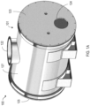
- FIGS. 1A and 1B show a process vessel 100.
- the process vessel 100 includes an outer shell 101 and an inner shell 102 disposed within the outer shell 101.
- the outer shell 101 includes a first outer end 123, a second outer end 125, and an outer shell wall 127 which defines a cylindrical shape that extends between the first outer end 123 and the second outer end 125.
- the outer shell 101 includes an inlet 122 on the outer shell wall 127.
- the outer shell 101 includes an outlet 124 on the first outer end 123.
- the absolute and relative size of the various components depicted in FIG. 1A can be varied as desired.
- the outer shell 101 may vary in overall size depending on various factors, such as the type or shape of mixers (described later) included within the outer shell 101, desired footprint of the process vessel 100 at a waste-to-energy facility, or desired size for the ability to transport a module including the process vessel 100 to a waste-to-energy facility. While depicted as cylindrical in FIG. 1A , in some embodiments, the outer shell 101 may include other shapes, such as cubic, cuboidal, spherical, or any irregular shape.
- the length of the outer shell 101 may range from about 5 feet to about 20 feet.
- the height and width of the outer shell 101 may each range from about 5 feet to about 10 feet.
- the outer shell 101 can have a length of about 9 feet, a width of about 6 feet, and a height of about 6 feet.
- the length-to-width ratio of the outer shell is from about 0.5 to about 4.0, e.g., from about 0.75 to about 3.0, from about 1.0 to about 2.5, or from about 1.5 to about 2.0.
- the length-to-height ratio of the outer shell is from about 0.5 to about 4.0, e.g., from about 0.75 to about 3.0, from about 1.0 to about 2.5, or from about 1.5 to about 2.0.
- the width-to-height ratio of the outer shell is from about 0.5 to about 2, e.g., from about 0.75 to about 1.75, or from about 1.0 to about 1.5.
- the inner shell 102 of the process vessel 100 is disposed within the outer shell 101.
- the inner shell 102 includes a first end 103, a second end 105, and a wall 107 extending between the first end 103 and the second end 105.
- the inner shell 102 defines a cavity 111 and a longitudinal axis 180a extending between the first end 103 and the second end 105.
- the outer shell 101 can include one or more metals (including alloys thereof), ceramics, polymers, composites, or combinations thereof.
- suitable materials for constructing the outer shell 101 include, but are not limited to, titanium, stainless steel, carbon steel, and combinations or alloys thereof.
- the material e.g., a metal
- the material includes an internal wetted surface, such as a metallic coating or metallic cladding suitable for providing oxidation resistance.
- the inner shell 102 can include one or more metals (including alloys thereof), ceramics, polymers, composites, or combinations thereof. Examples of suitable materials for constructing the inner shell 102 include, but are not limited to, titanium, 304 class stainless steel, 316 class stainless steel, appropriate chromium/nickel alloys, and other alloy variants resistant to oxidation and abrasion.
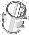
- FIGS. 2A and 2B show a process vessel 100.
- the first outer end 123 is omitted from the illustration shown in FIG. 2A for the purpose of showing the inside of the process vessel 100.
- a cross section of the inner shell 103 is transverse to the longitudinal axis 180a.
- the cross section includes a first arcuate inner wall portion 140a having a first radius of curvature 141a and a second arcuate inner wall portion 140b having a second radius of curvature 141b.
- the first radius of curvature 141b is larger than the second radius of curvature 141c.
- the cross section of the inner shell 103 transverse to the longitudinal axis 180a includes a third arcuate inner wall portion 140c and a fourth arcuate inner wall portion 140d.
- the second arcuate inner wall portion 140b can extend between the third arcuate inner wall portion 140c and the fourth arcuate inner wall portion 140d.
- the third arcuate inner wall portion 140c can have a third radius of curvature 141c
- the fourth arcuate inner wall portion 140d can have a fourth radius of curvature 141d.
- the third radius of curvature 141c and the fourth radius of curvature 141d are identical.
- the third radius of curvature 141c and the fourth radius of curvature 141d can be larger than the second radius of curvature 141b of the second arcuate inner wall portion 140b.
- the second arcuate inner wall portion 140b can form a channel 142 between curved surfaces formed by the third arcuate inner wall portion 140c and the fourth arcuate inner wall portion 140d.
- the process vessel 100 can include a heating structure coupled to or forming an exterior surface of the inner shell 102 or coupled to or forms an interior surface of the inner shell 102.
- the heating structure may be in the form of a heating jacket.
- a heating jacket 109 is coupled to or forms a surface of the wall 107 of the inner shell 102.
- the heating jacket 109 is disposed along or forms an exterior surface of the wall 107 of the inner shell 102.
- the heating jacket 109 is disposed along or forms an inner surface of the wall 107 of the inner shell 102.
- the heating jacket 109 can heat the wall 107 of the inner shell 102.
- any suitable heater design may be selected as the heating jacket 109, such as an electrical heating jacket, an inductive heating jacket, or a convective heating jacket (for example, a heated oil jacket).
- the heating jacket 109 transfers heat into the cavity 111, and the solid waste mixture may be heated within the cavity 111 through conduction from the heating jacket 109 to a portion of the solid waste mixture in contact with the heating jacket 109 and through convection.
- the heating structure e.g., heating jacket
- an exemplary heating structure includes half-pipe coil jackets, dimple jackets, plate coils, and pillow plates.
- a heat transfer fluid can be circulated through the heating structure (e.g., heating jacket 109) as a heating medium.
- the heat transfer fluid flows through the heating structure to provide heat to the process vessel 100.
- a heater can be included to heat the heat transfer fluid, and a circulation pump can be included to circulate the reheated heat transfer fluid to the heating structure.
- the heat transfer fluid can be, for example, a heated oil.
- the heating structure includes a hollow shell with heated oil circulating within the hollow shell.
- the heating structure is one, continuous member.
- the heating structure is made up of multiple, discrete portions.
- the heating structure can include multiple heating panels formed around and welded to the outer surface of the inner shell 102. The temperature of the heated oil may be increased by passing the oil through any suitable heat exchanger.
- the process vessel 100 can include a plurality of heating structures.
- the outer shell 101 is configured to withstand an internal vacuum.
- An annular enclosure 150 is defined between the outer shell 101 and the inner shell 102.
- the process vessel 100 can include a pump (e.g., a vacuum pump) operatively coupled to the outer shell 101 and the inner shell 102.
- the pump can be used so that a difference between the pressure in the cavity 111 and the pressure in the annular enclosure 150 is no greater than 2.27 kg (5 pounds) per 0.007 m 2 (square inch) (psi).
- the pump can be used such that the pressure within the cavity 111 and the pressure within the annular enclosure 150 are equal.
- the inner shell 102 does not experience a pressure differential because the pressure within the inner shell 102 (that is, the pressure within the cavity 111) and the pressure exterior to the inner shell 102 (that is, the pressure within the annular enclosure 150) are equal. Therefore, the inner shell 102 can have a thickness that is thinner in comparison to a shell that would need to be designed to withstand a pressure differential between an interior vacuum operation and the atmosphere. Additionally, the process vessel 100 can include an insulating material 108 disposed within the annular enclosure 150, so that heat losses to the surrounding environment (for example, through the outer shell 101 to the atmosphere) can be decreased. By surrounding the inner shell 102 with insulating material 108, the energy efficiency of the process vessel can be increased.
- Suitable insulating materials can withstand high temperature operation, for example, at least up to the maximum temperature of the heating structure (e.g., heating jacket 109).
- the insulating material 108 can be hydrophobic to reduce or prevent moisture buildup in the annular cavity.
- the insulating material 108 can be chemically inert to reduce or prevent deterioration of the insulating material over time.
- the insulating material 108 can optionally have a high density. Examples of suitable insulating materials include, but are not limited to, cellular gas and ceramic fiber.
- the insulating material 108 is coupled to the inner shell 102. In some embodiments, the insulating material 108 covers at least a portion of the heating jacket 109.
- the insulating material 108 is coupled to the heating jacket 109.
- the insulating material 108 can be coupled to the outer shell 101 (for example, an inner surface of the outer shell 101).
- the insulating material 108 can be coupled to the inner shell 102 (for example, an inner surface of the inner shell 102, an outer surface of the inner shell 102, or both).
- the insulating material 108 can be coupled to one or multiple support structures 152.
- the inner shell 102 is maintained in position within the outer shell 101 by a support structure 152 (best shown in FIG. 1B ) disposed within the annular enclosure 150.
- the support structure 152 can include a continuous body defined by a curved base and rib-like portions extending from the curved base. In some embodiments, portions (e.g., rib-like portions) of the support structure 152 can extend transverse to the longitudinal axis 180a and extend circumferentially about a portion of an exterior surface of the inner shell 102.
- the support structure 152 can be coupled to the outer shell 101 and the inner shell 102.
- the support structure 152 can absorb at least a portion of the mechanical stress generated from rotating components (such as mixers and extruder elements, which are described later).
- the support structures absorb a majority (that is, more than 50%) of the mechanical stress generated from rotating components. Because of the support structure 152, the inner shell 102 design can be configured to withstand thermal stresses associated with the heating used to form the solid fuel composition from the solid waste mixture. Examples of suitable materials for constructing the support structure 152 include, but are not limited to, 304 class stainless steel, 316 stainless steel, appropriate chromium/nickel alloys, and other alloy variants resistant to oxidation and weld-compatible with the inner shell 102 or inner liner material (if included on the inner surface of the inner shell 102).
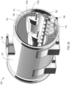
- FIGS. 3A and 3B show the process vessel 100 in which the first outer end 123 is omitted from the view for the purpose of showing inner components of the process vessel 100.
- the process vessel 100 includes a first mixer 113a, a second mixer 113b, and an extruder element 115.
- a “mixer” generally refers to a device suitable for mixing, agitating, or blending a composition
- “mix” generally refers to agitating materials, combining materials, or blending materials. That is, mixing does not necessarily result in a homogeneous mixture.
- an “extruder element” generally refers to a device suitable for densifying or shaping a solid composition
- “extruding” generally refers to densifying or shaping
- “extruded” generally refers to densified or shaped.
- the first mixer 113a, the second mixer 113b, and the extruder element 115 are disposed in the cavity 111 of the inner shell 102.
- the process vessel can include one mixer, or multiple mixers (e.g., three, four, five, or more than five mixers).
- the extruder element 115 can be disposed adjacent to the second arcuate inner wall portion 140b.
- the extruder element 115 can be disposed within the channel 142.
- the first mixer 113a can be disposed adjacent to the third arcuate inner wall portion 140c, and the second mixer 113a can be disposed adjacent to the fourth arcuate inner wall portion 140d.
- the extruder element 115 can move into and out of the process vessel the outlet 124.
- the extruder element 115 is a compression element configured to compress the solid waste mixture toward the opening, thereby forcing the solid waste mixture through the opening.
- the compression element can include a mixer blade, a screw conveyer, a piston, a compression pump, or the like.
- the extruder element 115 circulates material (for example, a composition such as a solid waste mixture) within the cavity 111 of the inner shell 102 or transport material (such as a solid fuel composition) out of the process vessel 100 through the outlet 124.
- material for example, a composition such as a solid waste mixture
- transport material such as a solid fuel composition
- the extruder element 115 When rotating in a second direction (for example, in a direction opposite the first direction), the extruder element 115 can circulate a composition in the cavity 111.
- the extruder element 115 can be an extrusion screw.
- the outlet 124 can optionally be heated to facilitate extrusion of the solid waste mixture out of the process vessel 100.
- the outlet 124 can be operatively connected to an extrusion heater, such as an electrical heater, an inductive heater, or a convective heater.
- the first mixer 113a is configured to rotate in a first direction
- the second mixer 113b is configured to rotate in a second direction opposite the first direction.
- the first mixer 113a can rotate in a clockwise direction
- the second mixer 113b can rotate in a counter-clockwise direction, or vice versa.
- Any known mixer design may be included in the process vessel 100 without limitation.
- the type and size of the mixers (113a, 113b) may be selected based on various factors, such as the ability to agitate the solid waste mixture (which can vary in density and viscosity), the ability to impart shear forces to the solid waste mixture, and energy requirements to drive the mixers 113a and 113b.
- the mixers 113a and 113b may include one or more mixer blades.
- the first mixer 113a and the second mixer 113b can be rotary mixing blades.
- the mixers 113a and 113b can be laterally spaced in close proximity to one another to enable grinding of the solid waste mixture between the mixers (113a, 113b), which are counter-rotating.
- “Grinding” generally includes any form of reducing a material into smaller pieces, such as break apart or shear, and does not necessarily mean, for example, that the material is pulverized into a powder.
- the extruder element 115 is spaced apart from each of the first mixer 113a and the second mixer 113b by a first gap 144a.
- the first mixer 113a and the second mixer 113b are spaced apart from each other by a second gap 144b.
- the second gap 144b is larger than the first gap 144a.
- the longitudinal axis 180a of the inner shell 102 is a first longitudinal axis 180a.
- the extruder element 115 defines a second longitudinal axis 180b.
- the first mixer 113a defines a third longitudinal axis 180c.
- the second mixer 113b defines a fourth longitudinal axis 180d.
- the second longitudinal axis 180b, the third longitudinal axis 180c, and the fourth longitudinal axis 180d can each be offset from the first longitudinal axis 180a.
- the first longitudinal axis 180a is equidistant from the third longitudinal axis 180c and the fourth longitudinal axis 180d.
- the first longitudinal axis 180a can be parallel to the second longitudinal axis 180b, the third longitudinal axis 180c, the fourth longitudinal axis 180d, or combinations of these.
- the second longitudinal axis 180b can be equidistant from the third longitudinal axis 180c and the fourth longitudinal axis 180d.
- the second longitudinal axis 180b, the third longitudinal axis 180c, and the fourth longitudinal axis 180d can form a triangular geometry in the cross section of the inner shell 102.
- the first longitudinal axis 180a, the second longitudinal axis 180b, the third longitudinal axis 180c, and the fourth longitudinal axis 180d can form a quadrilateral geometry in the cross section of the inner shell 102.
- the cross-sectional shape of the inner shell 102 can generally conform to the cross-sectional shapes of the first mixer 113a, second mixer 113b, and extruder element 115, so that the ratio between heated surface area (for example, the surface area of the heating jacket 109) and the volume of the inner cavity 111 can be increased in comparison to an inner shell with a cylindrical shape (that is, with a circular, cross-sectional shape).
- the heated surface area is equal to the sum of the heated portions (that is, portions carrying heating fluid, such as the circulating heating oil) of the heating structure (e.g., heating jacket 109).
- the "outer diameter" of a rotating component generally refers to double the length of the longest radius of the component; the outer diameter is also equal to the diameter of the overall cross-sectional shape of the component going through a full, 360-degree rotation about its longitudinal axis.
- an outer diameter of the first mixer 113a and an outer diameter of the second mixer 113b are equal.
- a ratio of the outer diameter of the first mixer 113a to an outer diameter of the extruder element 115 is at least about 1: 1 and at most about 3:1.
- the outer diameters of the first mixer 113a and the second mixer 113b can be about 0.91 m (36 inches), and the outer diameter of the extruder element 115 can be about 0.51 m (20 inches), resulting in a ratio of 1.8:1 for the outer diameter of the first mixer 113a to the outer diameter of the extruder element 115.
- the cavity 111 is subdivided into separate drying and mixing chambers.
- the drying chamber and the mixing chamber can independently be surrounded by the heating jacket 109 to heat contents of either chamber.
- a resealing door can be included in between the separate chambers, and the resealing door can be opened or otherwise moved to allow transfer of material between the drying chamber and the mixing chamber.
- a partition can be included in between the separate chambers, and the partition can be moved to allow transfer of material between the drying chamber and the mixing chamber.
- the process vessel 100 can include an exhaust port on the first shell wall 127 to provide an operative coupling to the pump (e.g., vacuum pump).
- the pump is connected to the exhaust port with a hose (e.g., a vacuum hose), which may be reinforced to prevent collapse during use.
- the hose may also be heat-resistant or include insulation to allow safe operation at temperatures up to the maximum temperature to which the solid waste mixture is heated within the process vessel 100.
- the pump can be selected to maintain a sufficiently low pressure as described in this disclosure, within the cavity 111.
- the pump may be placed on a stand or a raised platform to prevent the pump from exposure to liquid water during incidental flooding. Any pump design may be included without limitation.
- the pump can include a rotary vane pump, a diaphragm pump, or a liquid ring pump.
- the pump can optionally include one or more pumps connected in series.
- the pump includes a condenser operatively connected to the process vessel 100.
- the condenser cools water vapor and other vaporized compounds drawn from the cavity 111 by the pump to produce wastewater.
- the wastewater can be transferred to a wastewater reservoir, such as another vessel or a tank.
- a water treatment device operatively coupled to the wastewater reservoir can be configured to remove compounds from the condensed wastewater to produce treated wastewater.
- the water treatment device can include membrane filters, ozone chambers, activated carbon filters, or combinations thereof.
- the pump includes a gas scrubbing device, to which any air remaining in the condenser after the vaporized compounds have been condensed can pass through the pump and be exhausted.
- the gas exiting the pump (in other words, the exhaust) may include air, methane, chlorine, chlorinated organic compounds, and volatile organic compounds.
- the gas scrubbing device can include an adsorbent bed to separate methane and other combustible gases from the exhaust. The methane and other combustible gases captured by the adsorbent bed can be used as fuel, stored for later use, or be sold.
- the gas scrubbing device can include a gas filter, such as an activated carbon filter or a membrane filter. The gas remaining after treatment by the gas scrubbing device may be exhausted to the atmosphere.
- the process vessel 100 includes an air source operatively coupled to the process vessel 100 through an air inlet port.
- the air source can introduce sweep air into the cavity 111 of the inner shell 102 to facilitate movement of vaporized compounds out of the cavity 111 and into the pump.
- the air source can provide air at a flow rate selected to maintain the desired pressure (e.g., vacuum) within the cavity 111 while the pump is operating.
- the air source may be any known air source, such as a compressed air tank, an air compressor, an air pump, or a fan drawing in atmospheric air.
- the air source may supply an oxygen-free and non-reactive gas, such as nitrogen or a noble gas.
- the process vessel 100 includes a cutter configured to cut the solid waste mixture into discrete pieces, as the solid waste mixture is extruded out of the outer shell 101.
- the cutter can be a laser cutter, a saw, or a water jet cutter.
- the solid waste mixture is slightly cooled in order to harden the solid waste mixture prior to cutting.
- the solid waste mixture can be cut into discrete pieces that are less than about 2 feet in length.
- FIGS. 4A and 4B show an exemplary system 400.
- the system 400 includes a composition 450a (e.g., feedstock material), such as a solid waste mixture.
- the system 400 includes a process vessel 499 that can be substantially the same as the process vessel 100 described earlier.
- the process vessel 499 can process the composition 450a and form a solid fuel composition 450b from the composition 450a.
- the solid fuel composition 450b includes an energy content of at least about 18608000 J/kg (8,000 British thermal units per pound (BTU/lb)).
- the system 400 provided herein can be configured to process a composition 450a that includes solid waste.
- the solid waste can include solid, liquid, semi-solid, or contained gaseous material.
- the solid waste is wet.
- the solid waste is heterogeneous.
- the solid waste includes non-combustible material.
- the solid waste is material discarded from industrial, commercial, mining, agricultural, or community operations.
- the solid waste can include a mixture of solid waste having a variable composition due to the variable nature of municipal solid waste streams.
- the solid waste mixture may be derived from non-hazardous waste sources including, but not limited to, municipal waste, agricultural waste, commercial waste, household waste, mining waste, discarded secondary materials, industrial solid waste, and sewage sludge from a wastewater treatment plant, a water supply treatment plant, or an air pollution control facility.
- Municipal waste or “municipal solid waste” (MSW), as used here, generally refer to any household waste, commercial solid waste, or industrial solid waste.
- Non-limiting examples of wastes that can be included in the solid waste mixture include biodegradable waste, such as food and kitchen waste; green wastes, such as lawn or hedge trimmings; paper; mixed plastics; solid food waste; solid agricultural waste; sewage sludge; and automotive shredder residue.
- "Household waste” or “residential waste” generally refers to any solid waste (including garbage, trash, and sanitary waste in septic tanks) derived from households (including single and multiple residences, hotels and motels, bunkhouses, ranger stations, crew quarters, campgrounds, picnic grounds, and day-use recreation areas).
- “Commercial solid waste” generally refers to all types of solid waste generated by stores, offices, restaurants, warehouses, and other non-manufacturing activities.
- Industrial solid waste generally refers to non-hazardous solid waste generated by manufacturing or industrial processes.
- industrial solid waste include, but are not limited to, waste resulting from manufacturing processes, such as electric power generation; fertilizer and agricultural chemicals; food and related products and by-products; leather and leather products; organic chemicals; plastics and resins manufacturing; pulp and paper products; rubber and miscellaneous plastic products; textile manufacturing; transportation equipment; and water treatment.
- the composition 450a can include solid waste containing water.
- the solid waste can contain a variable amount of water ranging from about 10 wt % to about 60 wt %.
- the solid waste contains an amount of water ranging from about 10 wt % to about 20 wt %, from about 10 wt % to about 30 wt %, 10 wt % to about 40 wt %, or 10 wt % to about 50 wt %.
- the solid waste contains at least 10 wt % water, at least 20 wt % water, at least 30 wt % water, at least 40 wt % water, or at least 50 wt % water.
- the solid waste contains less than 20 wt % water, less than 30 wt % water, less than 40 wt % water, less than 50 wt % water, or less than 60 wt % water.
- the amount of water in the solid waste can influence the time and/or temperature associated with removing the water from the solid waste during the formation of the solid fuel composition.
- the composition 450a can include solid waste containing plastics.
- the solid waste includes at least about 20 wt % plastics.
- the solid waste includes from about 20 wt % to about 60 wt % plastics.
- the solid waste includes from about 20 wt % to about 40 wt % mixed plastics.
- the feedstock for the process includes between about 5 wt % to about 35 wt % mixed plastics.
- the feedstock for the process includes between about 5 wt % to about 30 wt % mixed plastics.
- the feedstock for the process includes greater than about 5 wt % plastics, greater than about 10 wt % plastics, greater than about 15 wt % plastics, greater than about 20 wt % plastics, greater than about 25 wt % plastics, greater than about 30 wt % plastics, greater than about 35 wt % plastics, greater than about 40 wt % plastics, greater than about 45 wt % plastics, greater than about 50 wt % plastics, or greater than about 55 wt % plastics.
- the process vessel 499 includes an inlet opening 422, an outlet opening 424, an outer shell 401, and an inner shell 402 disposed within the outer shell 401.
- the components of the process vessel 499 can be substantially the same as analogous components of the process vessel 100.
- the inner shell 401 of the process vessel 499 is substantially the same as the inner shell 102 of the process vessel 100 (best shown in FIG. 1B ).
- the inner shell 401 includes a first end (e.g., the first end 103), a second end (e.g., the second end 105), and a wall (e.g., the wall 107) extending between the first end and the second end.
- the inner shell 401 defines a cavity 411 to hold the composition 450a during processing.
- the inner shell 401 defines a longitudinal axis 480a extending between the first end and the second end.
- a cross section of the inner shell 401 transverse to the longitudinal axis 180a includes a first arcuate inner wall portion 440a having a first radius of curvature and a second arcuate inner wall portion 440b having a second radius of curvature.
- the first radius of curvature is larger than the second radius of curvature (see analogous radii of curvature of process vessel 100).
- the process vessel 499 includes an annular enclosure 450 defined between the outer shell 401 and the inner shell 402.
- the process vessel 499 can include a heating structure (e.g., the heating jacket 409 coupled to the wall of the inner shell 402), and the heating structure can heat the wall of the inner shell 402.
- the process vessel 499 can include an insulating material 408 disposed within the annular enclosure 450.
- the process vessel 499 can include a pump system operatively coupled to the outer shell 401 and the inner shell 402.
- the pump system can reduce the pressure or generate a vacuum within the cavity 411, the annular enclosure 450, or both.
- the pump system can set the cavity 411 at a first pressure and the annular enclosure 450 at a second pressure.
- the first pressure of the cavity 411 and the second pressure of the annular enclosure 450 can be equal.
- a pressure differential between the first pressure of the cavity 411 and the second pressure of the annular enclosure 450 is no greater than 5 psi.
- the cross section of the inner shell 402 transverse to the longitudinal axis 480a can include a third arcuate inner wall portion 440c and a fourth arcuate inner wall portion 440d.
- the process vessel 499 includes an extruder element 415, a first mixer 413a, and a second mixer 413b.
- the extruder element 415, the first mixer 413a, and the second mixer 413b can be disposed in the cavity 411 of the inner shell 402.
- the extruder element 415 can be disposed adjacent to the second arcuate inner wall portion 440b.
- the first mixer 413a can be disposed adjacent to the third arcuate inner wall portion 440c.
- the second mixer 413b can be disposed adjacent to the fourth arcuate inner wall portion 440d.
- the second arcuate inner wall portion 440b can form a channel, and the extruder element 415 can be disposed within the channel.
- the first mixer 413a can rotate the composition 450a in a first direction
- the second mixer 413b can rotate the composition 450a in a second direction opposite the first direction.
- the first mixer 413a and the second mixer 413b can counter-rotate.
- the extruder element 415 can circulate the composition 450a in the cavity 411 or transport the solid fuel composition 450b out of the process vessel 499 through the outlet opening 424.
- the extruder element 415 can transport the solid fuel composition 450b out of the process vessel 499 through the outlet opening 424.
- the extruder element 415 rotates in a second direction (for example, opposite to the first direction)
- the extruder element 415 can circulate the composition 450a in the cavity 411.
- the solid fuel composition 450b formed by the system 400 is provided herein.
- the solid fuel composition 450b has a uniform consistency and reduced variability in energy content relative to the compositions used to produce the solid fuel composition.
- the solid fuel composition 450b may have an energy content of at least 18608000 J/kg (8,000 BTU/lb), at least 20934000 J/kg (9,000 BTU/lb), at least 23260000 J/kg (10,000 BTU/lb), at least 25586000 J/kg (11,000 BTU/lb), at least 27912000 J/kg (12,000 BTU/lb), at least 30238000 J/kg (13,000 BTU/lb), at least 32564000 J/kg (14,000 BTU/lb), or at least 34890000 J/kg (15,000 BTU/lb).
- the solid fuel composition 450b has an energy content ranging from between about 18608000 J/kg (8,000 BTU/lb) to about 32564000 J/kg (14,000 BTU/lb).
- the solid fuel composition 450b has a density ranging from about 481 kg/m 3 (30 lb/ft 3 ) to about 1282 kg/m 3 (80 lb/ft 3 ). In some embodiments, the density of the solid fuel composition 450b is at least 481 kg/m 3 (30 lb/ft 3 ), at least 641 kg/m 3 (40 lb/ft 3 ), at least 802 kg/m 3 (50 lb/ft 3 ), at least 962 kg/m 3 (60 lb/ft 3 ), or at least 1122 kg/m 3 (70 lb/ft 3 ). In some embodiments, the solid fuel composition 450b has a density of about 802 kg/m 3 (50 lb/ft 3 ).
- the solid fuel composition 450b can include carbon. In some embodiments, the solid fuel composition 450b includes from about 40 wt % to about 80 wt % carbon. In some embodiments, the solid fuel composition 450b includes from about 40 wt % to about 44 wt %, from about 42 wt % to about 46 wt %, from about 44 wt % to about 48 wt %, from about 46 wt % to about 50 wt %, from about 48 wt % to about 52 wt %, from about 50 wt % to about 54 wt %, from about 52 wt % to about 56 wt %, from about 54 wt % to about 58 wt %, from about 56 wt % to about 62 wt %, from about 60 wt % to about 64 wt %, from about 62 wt % to about 66 wt %, from about 64 wt %
- the solid fuel composition 450b can include hydrogen. In some embodiments, the solid fuel composition 450b includes from about 5 wt % to about 20 wt % hydrogen. In some embodiments, the solid fuel composition 450b includes from about 5 wt % to about 7 wt % hydrogen, from about 6 wt % to about 8 wt % hydrogen, from about 7 wt % to about 9 wt % hydrogen, from about 8 wt % to about 10 wt % hydrogen, from about 9 wt % to about 11 wt % hydrogen, from about 10 wt % to about 12 wt % hydrogen, from about 11 wt % to about 13 wt % hydrogen, from about 12 wt % to about 14 wt % hydrogen, from about 13 wt % to about 15 wt % hydrogen, from about 14 wt % to about 16 wt % hydrogen, from about 15 wt % to about 17 wt % hydrogen, from
- the solid fuel composition 450b can include oxygen. In some embodiments, the solid fuel composition 450b includes from about 5 wt % to about 20 wt % oxygen. In some embodiments, the solid fuel composition 450b includes from about 5 wt % to about 7 wt % oxygen, from about 6 wt % to about 8 wt % oxygen, from about 7 wt % to about 9 wt % oxygen, from about 8 wt % to about 10 wt % oxygen, from about 9 wt % to about 11 wt % oxygen, from about 10 wt % to about 12 wt % oxygen, from about 11 wt % to about 13 wt % oxygen, from about 12 wt % to about 14 wt % oxygen, from about 13 wt % to about 15 wt % oxygen, from about 14 wt % to about 16 wt % oxygen, from about 15 wt % to about 17 wt % oxygen, from
- the solid fuel composition 450b can include no sulfur, or minimal amounts of sulfur. In some embodiments, the solid fuel composition 450b includes less than about 2 wt % sulfur. In some embodiments, the solid fuel composition 450b includes less than about 1 wt % sulfur, less than about 0.5 wt % sulfur, or less than about 0.1 wt % sulfur.
- the solid fuel composition 450b can include no chlorine, or minimal amounts of chlorine.
- the solid fuel composition 450b may include less than about 2 wt % chlorine.
- the solid fuel composition 450b includes less than about 1 wt % chlorine, less than about 0.5 wt % chlorine, and less than about 0.1 wt % chlorine.
- the solid fuel composition 450b can include no water, or minimal amounts of water.
- the solid fuel composition may include less than about 2 wt % water.
- the solid fuel composition 450b includes less than about 1 wt % water, less than about 0.5 wt % water, and less than about 0.1 wt % water. In some embodiments, the solid fuel composition 450b includes less than about 1 wt % water.
- the solid fuel composition 450b when burned, may release significantly lower levels of toxins when burned compared to unprocessed compositions (e.g., unprocessed solid waste).
- the amount of toxins released can vary.
- the solid fuel composition 450b can release less than about 0.23 kg (0.5 lb) alkali oxide, less than about 1.36 kg (3 lb) ash, less than about 0.05 kg (0.1 lb) sulfur dioxide (SO 2 ), and less than about 0.68 kg (1.5 lb) of chlorine per 1.06 million kJ (BTU) when burned.
- the solid fuel composition 450b releases less than about 0.23 kg (0.5 lb) alkali oxide per 1.06 million kJ (BTU) when burned.
- the solid fuel composition 450b releases less than about 1.36 kg (3 lb) ash per 1.06 million kJ (BTU) when burned. In some embodiments, the solid fuel composition 450b releases less than about 0.05 kg (0.1 lb) sulfur dioxide (SO 2 ) per 1.06 million kJ (BTU) when burned. In some embodiments, the solid fuel composition 450b releases less than about 0.68 kg (1.5 lb) of chlorine per 1.06 million kJ (BTU) when burned.
- the solid fuel composition 450b may release an amount of ash ranging from between about 1 lb and about 30 lb per million kJ (BTU) when burned, such as between about 0.45 kg (1 lb) and 0.9 kg (2 lb), between about 0.9 kg (2 lb) and 1.36 kg (3 lb), between about 1.36 kg (3 lb) and 1.81 kg (4 lb), between about 1.81 kg (4 lb) and 2.27 kg (5 lb), between about 2.27 kg (5 lb) and 4.54 kg (10 lb), between about 4.54 kg (10 lb) and 6.80 kg (15 lb), between about 6.80 kg (15 lb) and 9.07 kg (20 lb), between about 9.07 kg (20 lb) and 11.33 kg (25 lb), or between about 11.33 kg (25 lb) and 13.6 kg (30 lb).
- the solid fuel compositions may be used as an engineered feedstock to replace or supplement coal, biomass, or other alternative fuels during an incarnation, pyr
- FIG. 5 depicts a flow chart of a method 500 for forming a solid composition (such as the solid fuel composition 450b) from a composition (such as the composition 450a).
- the composition 450a can be introduced into a process vessel, such as the process vessel 499.
- the composition 450a is a solid waste mixture and is introduced into the process vessel 499 from above, through the inlet opening 422.
- the composition 450a is heated within the process vessel 499.
- the composition can be heated to a temperature of about 37.8 °C (100 degrees Fahrenheit (°F)) using the heating structure (e.g., heating jacket 109).
- the heating step 502 can be categorized into three heating cycles: the first heating cycle includes increasing the temperature of the solid waste mixture 450a to the water evaporation temperature; the second heating cycle includes maintaining the temperature of the solid waste mixture 450a at the water evaporation temperature to remove water from the solid waste mixture 450a; and the third heating cycle includes increasing and maintaining the temperature of the solid waste mixture 450a to the extrusion temperature.
- a vacuum can be pulled within the process vessel 499, such that a pressure within the cavity 411 is below atmospheric pressure. In some embodiments, the pressure within the process vessel 499 (and within the cavity 411) is maintained at about 50 torr.
- the vacuum not only reduces the boiling temperature of water and other compounds in the composition 450a, but also removes any of the vaporized compounds released by the heated solid waste. Reducing the boiling temperature of water and other compounds can reduce the necessary heating time and heating temperature to vaporize the compounds from the composition 450a. Reducing the heating time and heating temperature can reduce the necessary energy consumption to form the solid fuel composition 450b from the composition 450a.
- the vaporized compounds can include steam (that is, vaporized water).
- the vacuum can be generated by a vacuum pump or system connected to the outer shell 401 and the inner shell 402. Sweep air may be introduced into the process vessel 499 to facilitate movement of vaporized compounds out of the process vessel 499.
- the vacuum maintained within the process vessel 499 can also prevent combustion of material as the composition 250a is heated and dried.
- the pressure within the process vessel 499 (that is, within the cavity 411 and the annular enclosure 450) is maintained to less than about 6666 Pa (50 torr), 6000 Pa (45 torr), 5333 Pa (40 torr), 4666 Pa (35 torr), 4000 Pa (30 torr), 3333 Pa (25 torr), 2666 Pa (20 torr), 2000 Pa (15 torr), 1333 Pa (10 torr), or 667 Pa (5 torr).
- the range of pressures maintained within the process vessel 499 can vary.
- the pressure maintained within the process vessel 499 can vary between about 667 Pa (5 torr) and about 13332 Pa (100 torr), between about 5333 Pa (40 torr) and about 7999 Pa (60 torr), between about 667 Pa (5 torr) and about 1333 Pa (10 torr), between about 1333 Pa (10 torr) and about 2000 Pa (15 torr), between about 2000 Pa (15 torr) and about 2666 Pa (20 torr), between about 2666 Pa (20 torr) and about 3333 Pa (25 torr), between about 3333 Pa (25 torr) and about 4000 Pa (30 torr), between about 4000 Pa (30 torr) and about 4666 Pa (35 torr), between about 4666 Pa (35 torr) and about 5333 Pa (40 torr), between about 5333 Pa (40 torr) and about 6000 Pa (45 torr), between about 6000 Pa (45 torr) and about 6666 Pa (50 torr), between about 6666 Pa (50 torr
- the composition 450a can be mixed with the first and second mixers (413a, 413b) disposed in the cavity 411 of the inner shell 402.
- “mixed” generally refers to "agitated” or “blended.”
- the composition 450a can be mixed by rotating the first and second mixers (413a, 413b) in opposite directions.
- the composition 450a can be circulated within the process vessel 499 by rotating the extruder element 415 in a first direction.
- the heating structure can provide heat to the composition 450a and maintain a temperature within the process vessel 499 (and within the cavity 411) at about 37.8 °C (100°F). In some embodiments, the heating structure provides heat to maintain a temperature within the process vessel 499 at about 204.4 °C (400°F).
- the range of temperatures maintained within the process vessel 499 can vary. The temperature maintained within the process vessel 499 can vary between about 37.8 °C (100°F) and about 204.4 °C (400°F). In some embodiments, the temperature within the process vessel 499 is maintained at about 37.8 °C (100°F) for a first duration and then at about 204.4 °C (400°F) for a second duration.
- the maximum temperature and processing conditions within the process vessel 499 can be controlled, such that the composition 450a does not undergo pyrolysis.
- the heating jacket 409 can be maintained at a temperature corresponding to a maximum temperature of the composition 450a, above which the composition 450a begins to undergo pyrolysis.
- the heating jacket 409 can be maintained at a temperature that is higher than the desired temperature of the composition 450a, so that the composition 450a can be heated up to its desired temperature more quickly.
- the heating jacket 409 can be maintained at a temperature that is higher than the desired temperature of the composition 450a in order to compensate for any potential heat losses.
- the heating jacket 409 can be maintained at a temperature that is about -12.2 °C (10°F) hotter than the desired temperature of the composition 450a.
- the heating jacket 409 can be maintained at a temperature of about 43.3 °C (110°F).
- the heating jacket 409 can be maintained at a temperature that is about 93.3 °C (200°F) hotter than the desired temperature of the composition 450a.
- the heating jacket 409 can be maintained at a temperature of about 315.6 °C (600°F).
- the desired temperature of the composition 450a can vary throughout the duration of heating (502) and mixing (504) of the composition 450a within the process vessel 499.
- the composition 450a can be heated and mixed within the process vessel 499 for a duration ranging from about 10 minutes to about 120 minutes.
- the composition 450b is formed within 60 minutes of heating (502) and mixing (504) the composition 450a within the process vessel 499.
- the duration of heating at 502 depends on various factors, such as the makeup of the composition 450a introduced into the process vessel 499, the temperature of the heating jacket 409, the specific heat capacities of the various components of the composition 450a, the mixing speed (that is, the rotational speed of the mixers 413a and 413b), and targeted specifications or characteristics of the fuel composition to be produced.
- the composition 450a may be heated (502) and mixed (504) for a duration ranging from about 10 minutes to about 120 minutes, about 15 minutes to about 25 minutes, from about 20 minutes to about 30 minutes, from about 25 minutes to about 35 minutes, from about 30 minutes to about 40 minutes, from about 35 minutes to about 45 minutes, from about 40 minutes to about 50 minutes, from about 45 minutes to about 55 minutes, from about 50 minutes to about 60 minutes, from about 55 minutes to about 65 minutes, from about 60 minutes to about 90 minutes, from about 75 minutes to about 105 minutes, and from about 90 minutes to about 120 minutes.
- the composition 450a may be heated and mixed within the process vessel 499 for a duration of about 40 minutes.
- the composition 450a can be extruded from the process vessel 499 (for example, through the outlet 424) with the extruder element 415 disposed in the cavity 411 of the inner shell 402.
- extrude generally refers to densify or shape.
- the extruder element 415 can be a screw conveyer or an extrusion screw that may be operated in one direction to circulate the composition 450a within the cavity 411 and operated in a reverse direction to extrude the composition 450a out of the process vessel 499 through the outlet 424.
- the extruder element can be any component or arrangement of components (e.g., an extruder with no diehead) configured to densify or shape the composition 450a.
- a solid composition (such as the solid fuel composition 450b) is formed from the composition 450a.
- the solid fuel composition 450b has an energy content of at least 18608000 J/kg (8,000 BTU/lb).
- the solid fuel composition 450b can be sterile, hydrophobic, chemically stable, non-biodegradable, or a combination of these.
- “Sterile” generally refers to the solid fuel composition 450b being substantially free of living microorganisms after being produced.
- “Stable” or “chemically stable” generally refers to the solid fuel composition 450b not substantially changing in chemical properties, physical properties, or structure upon extended contact with water, oxygen, ambient conditions, or ordinary storage conditions.
- the solid fuel composition 450b is stable until the solid fuel composition 450b is combusted, undergoes pyrolysis, or is employed as feedstock in a similar process.
- Non-biodegradable generally refers to the solid fuel composition 450b not degrading, deposing, or decomposing under ordinary biological action, such as rotting or composting.
- the solid fuel composition 450b can be stored for extended periods at a various storage conditions, used as feedstock to a collocated waste-to-energy facility, transported to a remote waste-to-energy facility, or used to provide energy for the process vessel 499 itself, any associated devices, or other processes.
- the method 500 of forming a solid composition can be completed as a batch process, in which, for example, the solid waste mixture 450a is introduced to the process vessel 499, processed, and then extruded to form the solid fuel composition 450b. Once the solid fuel composition 450b has been completely extruded from the process vessel 499, another batch can be initiated.
- the method 500 can be completed as a semi-continuous process.
- the outer shell 401 of the process vessel 499 had an inside diameter in a range between 1.52 m (60 inches) and 2.29 m (90 inches).
- the outer shell 401 had a length in a range between 2.29 m (90 inches) and 3.2 m (126 inches).
- Each of the at least two mixing blades (the first mixer 413a and the second mixer 413b) had an outer diameter in a range between 0.76 m (30 inches) and 1.07 m (42 inches).
- the extrusion screw (the extruder element 415) had an outer diameter in a range between 12 inches and 0.76 m (30 inches).
- the second arcuate inner wall portion 440b of the cross-sectional shape of the inner shell 402 had a central angle (with respect to the extruder element 415) in a range between 230° and 270°.
- the third and fourth arcuate inner wall portions (440c, 440d) of the cross-sectional shape of the inner shell 402 had central angles (with respect to the corresponding mixers, 413a and 413b) in a range between 100° and 140°.
- the total inner volume of the process vessel 499 (that is, the volume within the outer shell 401) was in a range of 5,947 liters (L) (210 cubic feet (ft 3 )) and 6,513 L (230 ft 3 ).
- the working volume of the process vessel 499 (that is, the volume within which the solid waste mixture 450a is circulated, heated, and mixed, which is equal to the volume within the inner shell 402 excluding the volume taken up by the first mixer 413a, the second mixer 413b, and the extruder element 415 within the inner shell 402) was in a range of 5,239 L (185 ft 3 ) and 5,805 L (205 ft 3 ).
- the total area of the cross-sectional shape of the inner shell 402 was in a range between 1.86 m 2 (20 square feet (ft 2 )) and 2.79 m 2 (30 ft 2 ).
- the heating jacket 409 lined the outer surface of the inner shell 402 and defined the heated surface area.
- the heated surface area was in a range between 16.72 m 2 (180 ft2) and 20.44 m 2 (220 ft 2 ).
- the ratio between the heated surface area and the total surface area of the process vessel 499 was in a range between 0.5 and 0.9.
- the heating jacket 409 was supplied with hot oil (Duratherm 630 TM ) at a flow rate in a range between 492 L per minute (130 gallons per minute (gpm)) and 644 L per minute (170 gpm) and a temperature in a range between 315.6 °C (600°F) and 343.3 °C (650°F).
- Hot oil Diuratherm 630 TM
- the process of forming the solid fuel composition 450b from the solid waste mixture 450a was completed as a batch process, in which the solid waste mixture 450a was introduced to the process vessel 499, processed, and then extruded to form the solid fuel composition 450b. Once the solid fuel composition 450b was completely extruded from the process vessel 499, another batch was initiated.
- the process was categorized into three heating cycles: the first heating cycle which included increasing the temperature of the solid waste mixture 450a to the water evaporation temperature; the second heating cycle which included maintaining the temperature of the solid waste mixture 450a at the water evaporation temperature to remove water from the solid waste mixture 450a; and the third heating cycle which included increasing and maintaining the temperature of the solid waste mixture 450a to the extrusion temperature.
- the total process took 30 minutes to 60 minutes to complete.
- the mass of total solid fuel composition 450b formed in a single batch was in a range between 80% and 99% of the total original mass of the solid waste mixture 450a introduced to the process vessel 499 (includes moisture content).
Landscapes
- Chemical & Material Sciences (AREA)
- Organic Chemistry (AREA)
- Oil, Petroleum & Natural Gas (AREA)
- Engineering & Computer Science (AREA)
- Chemical Kinetics & Catalysis (AREA)
- Combustion & Propulsion (AREA)
- Materials Engineering (AREA)
- Physics & Mathematics (AREA)
- Thermal Sciences (AREA)
- Life Sciences & Earth Sciences (AREA)
- Geochemistry & Mineralogy (AREA)
- Environmental & Geological Engineering (AREA)
- General Life Sciences & Earth Sciences (AREA)
- Agronomy & Crop Science (AREA)
- Geology (AREA)
- Processing Of Solid Wastes (AREA)
- Containers Having Bodies Formed In One Piece (AREA)
- Filling Or Discharging Of Gas Storage Vessels (AREA)
- Details Of Rigid Or Semi-Rigid Containers (AREA)
- Solid Fuels And Fuel-Associated Substances (AREA)
Description
- This disclosure relates to a process vessel for producing solid compositions, as well as related systems and methods. In particular, a process vessel for producing solid fuel compositions from solid wastes are disclosed herein.
- It is desirable to manage solid wastes, such as municipal wastes from residential, institutional, and commercial sources, agricultural wastes, and other wastes such as sewage sludge. As landfills reach and exceed capacity worldwide, and as the solid waste industry and societies generally limit the use of landfills, methods of managing solid wastes have been developed to reduce the volume of solid waste introduced into landfills. Recycling of metals, plastics, and paper products, as well as composting organic matter are methods of reducing the overall volume of solid wastes going to landfills. Waste-to-energy processes have also been developed to convert the energy content of solid wastes into a more usable form, such as electrical power.
-
US 2015/0368563 A1 describes a continuous-feed pyrolyzer for converting waste material into ash or char and a combustible gas. -
US 2013/0240343 A1 describes a char making apparatus that includes a longitudinal pyrolyzer furnace housing wherein coal-bearing material may be heated to a temperature to fluidize volatile materials therein and plasticize coal in the coal-bearing material. -
EP 2127738 A1 describes a device with rotative fluidized bed for thermal and/or catalytic transformation of two different reactive fluids that includes a reactor including an annular chamber containing solid particles, a device for supplying the solid particles in the annular chamber, and a device for evacuation of solid particles from the annular chamber - The present invention is defined by the independent claims. The dependent claims depict additional embodiments of the invention. This disclosure relates to a process vessel for producing compositions, such as solid fuel compositions, having a desired homogeneity, density and/or moisture content, as well as related systems and methods. In particular, some embodiments provided herein include a process vessel, a system, and a method for producing solid fuel compositions from solid wastes. For example, the process vessel provided herein can produce a desired composition (e.g., a solid fuel composition) from feedstock materials (e.g., solid wastes and other wastes).
- In one general aspect, this disclosure provides a process vessel including a first shell and a second shell disposed within the first shell. The second shell includes a first end, a second end, and a wall extending between the first end and the second end. The second shell defines a cavity and a longitudinal axis extending between the first end and the second end. A cross section of the second shell transverse to the longitudinal axis includes a first arcuate inner wall portion having a first radius of curvature. The cross section of the second shell transverse to the longitudinal axis includes a second arcuate inner wall portion having a second radius of curvature. The first radius of curvature is larger than the second radius of curvature. An annular enclosure is defined between the first shell and the second shell. The process vessel includes one or more support structures disposed within the annular enclosure. At least a portion of the support structure extends transverse to the longitudinal axis and extends circumferentially about a portion of an exterior surface of the second shell. The first shell includes a first outer end, a second outer end, and first shell wall defining a cylindrical shape that extends between the first outer end and the second outer end. The cross section of the second shell transverse to the longitudinal axis includes a third arcuate inner wall portion and a fourth arcuate inner wall portion.
- Certain aspects of the subject matter described in this disclosure can be implemented as a system for producing a solid fuel composition, the system including a composition and a process vessel as described above and configured for processing the composition. The process vessel further includes an inlet opening, an outlet opening, and the process vessel is configured to form, from the composition, a solid fuel composition including an energy content of at least about 18608000 J/kg (8,000 British thermal units per pound).
- Certain aspects of the subject matter described in this disclosure can be implemented as a method for producing a solid fuel composition. A composition is heated within a process vessel. The process vessel includes a first shell and a second shell disposed within the first shell. The second shell includes a first end, a second end, a wall extending between the first end and the second end, and a heating jacket coupled to the wall. The heating jacket is configured to heat the wall. The second shell defines a cavity to hold the composition during processing. The second shell defines a longitudinal axis extending between the first end and the second end. A cross section of the second shell transverse to the longitudinal axis includes a first arcuate inner wall portion having a first radius of curvature and a second arcuate inner wall portion having a second radius of curvature. The first radius of curvature is larger than the second radius of curvature. An annular enclosure is defined between the first shell and the second shell. A support structure is disposed within the annular enclosure, wherein portions of the support structure extend transverse to the longitudinal axis and extending circumferentially about a portion of an exterior surface of the second shell. The first shell comprises a first outer end, a second outer end, and a first shell wall defining a cylindrical shape that extends between the first outer end and the second outer end. The cross section of the second shell transverse to the longitudinal axis includes a third arcuate inner wall portion and a fourth arcuate inner wall portion. The composition is mixed with first and second mixers disposed in the cavity of the second shell. As used herein, "mix" generally refers to agitate, combine, or blend. The composition is extruded with an extruder element disposed in the cavity of the second shell. As used herein, "extruded" generally refers to densified or shaped, and "extruder element" generally refers to a device suitable for densifying or shaping a solid composition. A solid fuel composition is formed from the composition. The solid fuel composition includes an energy content of at least about 18608000 J/kg (8,000 British thermal units per pound).
- The aspects provided above, and other aspects, can include one or more of the following features.
- The process vessel can include a heating jacket coupled to the wall of the second shell.
- The heating jacket can be disposed along an inner surface of the wall of the second shell.
- The heating jacket can be disposed along an exterior surface of the wall of the second shell.
- The process vessel can include an insulating material disposed within the annular enclosure.
- The process vessel can include a pump operatively coupled to the first and second shells, and the pump can be configured to reduce a pressure within the cavity, the annular enclosure, or both.
- The process vessel can be configured so that, during use of the pump, the cavity has a first pressure, and the annular enclosure has a second pressure. The first and second pressures can be within a 10% deviation.
- The second arcuate inner wall portion can extend between the third arcuate inner wall portion and the fourth arcuate inner wall portion.
- The third arcuate inner wall portion can have a third radius of curvature, and the fourth arcuate inner wall portion can have a fourth radius of curvature that is identical to the third radius of curvature
- The third arcuate inner wall portion and the fourth arcuate inner wall portion can each have a radius of curvature that is larger than the second radius of curvature of the second arcuate inner wall potion.
- The second arcuate inner wall portion can form a channel between curved surfaces formed by the third arcuate inner wall portion and the fourth arcuate inner wall portion.
- The process vessel can include an extruder element disposed in the cavity of the second shell, a first mixer disposed in the cavity of the second shell, and a second mixer disposed in the cavity of the second shell. The longitudinal axis can be a first longitudinal axis. The extruder element can define a second longitudinal axis. The first mixer can define a third longitudinal axis. The second mixer can define a fourth longitudinal axis.
- The extruder element can be disposed adjacent to the second arcuate inner wall portion. The first mixer can be disposed adjacent to the third arcuate inner wall portion. The second mixer can be disposed adjacent to the fourth arcuate inner wall portion.
- The extruder element can include an extrusion screw.
- The first mixer and the second mixer can each include a rotary mixing blade.
- The extruder element can be disposed within the channel.
- The extruder element can be spaced apart from each of the first mixer and the second mixer by a first gap, and the first mixer and the second mixer can be spaced apart from each other by a second gap.
- The second gap can be larger than the first gap.
- The second, third, and fourth longitudinal axes can be offset from the first longitudinal axis.
- The first longitudinal axis can be separated from the third longitudinal axis and the fourth longitudinal axis by a first distance and a second distance, respectively, where a difference between the first and second distances is no more than 5% of the first or second distance.
- The first longitudinal axis can be separated from the third longitudinal axis and the fourth longitudinal axis by a first distance and a second distance, respectively, where a difference between the first and second distances is no more than 0.5 meters (m).
- The first longitudinal axis can be parallel to the second longitudinal axis, the third longitudinal axis, the fourth longitudinal axis, or combinations of these.
- The second longitudinal axis can be separated from the third longitudinal axis and the fourth longitudinal axis by a third distance and a fourth distance, respectively, where a difference between the third and fourth distances is no more than 5% of the first or second distance.
- The second longitudinal axis can be separated from the third longitudinal axis and the fourth longitudinal axis by a third distance and a fourth distance, respectively, where a difference between the first and second distances is no more than 0.5 meters (m).
- The second, third, and fourth longitudinal axes can form a triangular geometry in the cross section of the second shell.
- The first, second, third, and fourth longitudinal axes can form a quadrilateral geometry in the cross section of the second shell.
- The second arcuate inner wall portion can define a central angle with respect to the extruder element. The central angle can extend from about 180 degrees (°) to about 300°.
- The third arcuate inner wall portion and the fourth arcuate inner wall portion can each define an arc length having an angle that extends from about 10 degrees (°) to about 60°.
- This, and other aspects, can include one or more of the following features.
- An annular enclosure can be defined between the first shell and the second shell.
- The system can include a heating jacket coupled to the wall of the second shell. The heating jacket can be configured to heat the wall of the second shell.
- The system can include an insulating material disposed within the annular enclosure.
- The system can include a pump system operatively coupled to the first and second shells, and the pump system can be configured to reduce the pressure or generate a vacuum within the cavity, the annular enclosure, or both.
- The pump system can be configured to set the cavity at a first pressure and set the annular enclosure at a second pressure, where the first and second pressures are equal.
- The pump system can be configured to set the cavity at a first pressure and set the annular enclosure to a second pressure, where a pressure differential between the first and second pressures is no greater than 2.27 kg (5 pounds) per 0.007 m2 (square inch).
- The cross section of the second shell transverse to the longitudinal axis can include a third arcuate inner wall portion and a fourth arcuate inner wall portion.
- The process vessel can include an extruder element disposed in the cavity of the second shell, a first mixer disposed in the cavity of the second shell, and a second mixer disposed in the cavity of the second shell.
- The extruder element can be disposed adjacent to the second arcuate inner wall portion. The first mixer can be disposed adjacent to the third arcuate inner wall portion. The second mixer can be disposed adjacent to the fourth arcuate inner wall portion.
- The second arcuate inner wall portion can form a channel. The extruder element can be disposed within the channel.
- The first mixer can be configured to rotate the composition in a first direction, and the second mixer can be configured to rotate the composition in a second direction opposite the first direction.
- The extruder element can be configured to circulate the composition in the cavity or transport the solid fuel composition out of the process vessel through the outlet opening.
- The extruder element can be configured to, when the extruder element is rotating in a first direction, transport the solid fuel composition out of the process vessel through the outlet opening.
- The extruder element can be configured to, when the extruder element is rotating in a second direction, circulate the composition in the cavity.
- The subject matter described in this disclosure can be implemented in particular embodiments, so as to realize one or more of the following advantages. For example, in various embodiments, the process vessel provided herein can be used to transform a feedstock material(s) into a more useful composition by modifying, reducing, and/or eliminating one or more characteristics and/or elements of the feedstock material. For example, in some embodiments, the process vessel provided herein can form a desired composition (e.g., a solid fuel composition) from a feedstock (e.g., solid waste) that reduces or eliminates odors, bacteria, and other undesirable properties of the feedstock. In some embodiments, the process vessel described herein transforms a feedstock material (e.g., solid waste) having a variable composition (e.g., a mixture of different types of solid waste) into a composition (e.g., a solid fuel composition) that is a relatively consistent (e.g., homogeneous), more compact (e.g., having a high density), and/or has a low moisture content (e.g., dry, < 2 wt. % water).
- In some embodiments, the process vessel provided herein can provide a solid fuel composition in the form of a homogenized, dry, dense, and energy-rich fuel primed for subsequent processing (e.g., pyrolysis or gasification). For example, the process vessel provided herein can produce a desired composition (e.g., a solid fuel composition) that provides efficient operation for subsequent processing (e.g., feedstock for a pyrolysis or gasification chamber as part of a waste-to-energy process) without additional capital investment in advanced machinery. The process vessel provided herein can produce the desired composition in a compact form having a density of at least 321 kg/m3 (20 pounds per cubic foot (lb/ft3)). In some embodiments, the process vessel provided herein produce the desired composition in a compact form having a density in a range from 321 kg/m3 (20 lb/ft3) to 1282 kg/m3 (80 lb/ft3), from 481 kg/m3 (30 lb/ft3) to 1122 kg/m3 (70 lb/ft3), from 641 kg/m3 (40 lb/ft3) to 962 kg/m3 (60 lb/ft3), or from 673 kg/m3 (42 lb/ft3) to 914 kg/m3 (57 lb/ft3). The process vessel provided herein can produce the desired composition having a moisture content of no more than 45 weight percent (wt %). In some embodiments, the process vessel provided herein produces the desired composition having a moisture content in a range from 1 wt % to 45 wt %, from 1 wt % to 15 wt %, from 1 wt % to 20 wt %, from 1 wt % to 30 wt %, from 1 wt % to 40 wt %, from 10 wt % to 40 wt %, or from 20 wt % to 30 wt %.
- In some embodiments, the process vessel provided herein provides a suitable design for heating, mixing, drying, and/or extruding the feedstock materials. For example, certain embodiments of the process vessel provided herein define a volume suitable for mixing and heating a composition (e.g., solid waste) such that air voids within the final composition (e.g., solid fuel composition) is reduced and/or to provide uniform dispersion of components in the final composition. In some embodiments, the process vessel includes at least two mixers (e.g., mixing blades) configured to actuate in a counter-rotation direction with respect to one another to improve circulation and mixing of the composition (e.g., solid waste) during processing. The configuration of the process vessel and manner in which the components move with respect to one another can improve moisture removal from the composition (e.g., solid waste). For example, the at least two mixers can circulate the composition (e.g., solid waste), such that moisture does not get entrapped or entrained within the composition. In some embodiments, the process vessel provided herein includes a pump for reducing pressure and/or removing moisture from the materials during processing of the composition (e.g., solid waste) at lower temperatures, which can reduce processing time, heat, and energy required for producing the desired final composition (e.g., solid fuel composition). The process vessel provided herein includes inner and outer shells. The inner and outer shell configuration can reduce inner structural reinforcement, which may otherwise be necessary due to vacuum operation within the process vessel. The inner and outer shell configuration can also increase heat transfer surface area, thereby increasing the overall heating efficiency of the process. The inner and outer shell configuration also enables the overall system to be rated for full vacuum operation. Vacuum operation also allows for higher operating temperatures to be achieved within the process vessel without the risk of combustion occurring within the process vessel. Breakdown of organic matter can be improved in vacuum operation within the process vessel provided herein. In some embodiments, the disclosure provides a size-efficient process vessel that can produce a densified, dry (e.g., < 2 wt. % water) composition.
- The details of one or more embodiments of the subject matter of this disclosure are set forth in the accompanying drawings and the description. Other features, aspects, and advantages of the subject matter will become apparent from the description, the drawings, and the claims.
-
-
FIG. 1A is a perspective view of a process vessel. -
FIG. 1B is a perspective view showing an inner shell of the process vessel ofFIG. 1A . -
FIG. 2A is another perspective view of the process vessel ofFIG. 1A . -
FIG. 2B is a cross-sectional view of the process vessel ofFIG. 1A . -
FIG. 3A is another perspective view of the process vessel ofFIG. 1A . -
FIG. 3B is another cross-sectional view of the process vessel ofFIG. 1A . -
FIG. 4A is a perspective view of a system including the process vessel ofFIG. 1A . -
FIG. 4B is a cross-sectional view of the system ofFIG. 4A . -
FIG. 5 is a flow chart of a method for forming a solid composition. - This disclosure describes a process vessel for producing compositions, such as solid fuel compositions, as well as related systems and methods. In particular, the process vessel provided herein can produce a desired composition (e.g., a solid fuel composition) from feedstock materials (e.g., solid wastes and other wastes). For example, various embodiments of a process vessel (or a system) and a method for producing solid fuel compositions from a solid waste mixture are disclosed herein. In various embodiments, the process vessel provided herein is configured to process feedstock material that includes waste (e.g., solid waste). As used herein, "waste" refers to carbon-containing combustible material discarded after its primary use, and "solid waste" is any garbage, refuse, or sludge.
- In some embodiments, the process vessel provided herein is not limited to producing solid fuel compositions. For example, the process vessel (or a system) and method relating thereto provided herein may be used to produce other types of compositions from feedstock materials (e.g., a mixture of materials). In some embodiments, the process vessel provided herein can produce a desired composition (e.g., a uniformly mixed or blended solid composition) from feedstock materials (e.g., a mixture of different materials). In some embodiments, the process vessel provided herein can produce the desired composition having a moisture content less than the moisture content of the feedstock materials. For example, the process vessel provided herein can produce the desired composition having a moisture content of no more than 45 weight percent (wt %). In some embodiments, the process vessel provided herein can produce the desired composition in a compact form having a density higher than the density of the feedstock materials. For example, the process vessel provided herein can produce the desired composition in a compact form having a density of at least 20 pounds per cubic feet (lb/ft3).
-
FIGS. 1A and1B show aprocess vessel 100. Theprocess vessel 100 includes anouter shell 101 and aninner shell 102 disposed within theouter shell 101. Theouter shell 101 includes a firstouter end 123, a secondouter end 125, and anouter shell wall 127 which defines a cylindrical shape that extends between the firstouter end 123 and the secondouter end 125. Theouter shell 101 includes aninlet 122 on theouter shell wall 127. Theouter shell 101 includes anoutlet 124 on the firstouter end 123. In general, the absolute and relative size of the various components depicted inFIG. 1A can be varied as desired. For example, Theouter shell 101 may vary in overall size depending on various factors, such as the type or shape of mixers (described later) included within theouter shell 101, desired footprint of theprocess vessel 100 at a waste-to-energy facility, or desired size for the ability to transport a module including theprocess vessel 100 to a waste-to-energy facility. While depicted as cylindrical inFIG. 1A , in some embodiments, theouter shell 101 may include other shapes, such as cubic, cuboidal, spherical, or any irregular shape. - The absolute and relative size of the outer shell can be varied as desired. For example, in some embodiments, the length of the
outer shell 101 may range from about 5 feet to about 20 feet. In some embodiments, the height and width of theouter shell 101 may each range from about 5 feet to about 10 feet. In some embodiments, theouter shell 101 can have a length of about 9 feet, a width of about 6 feet, and a height of about 6 feet. In some embodiments, the length-to-width ratio of the outer shell is from about 0.5 to about 4.0, e.g., from about 0.75 to about 3.0, from about 1.0 to about 2.5, or from about 1.5 to about 2.0. In some embodiments, the length-to-height ratio of the outer shell is from about 0.5 to about 4.0, e.g., from about 0.75 to about 3.0, from about 1.0 to about 2.5, or from about 1.5 to about 2.0. In some embodiments, the width-to-height ratio of the outer shell is from about 0.5 to about 2, e.g., from about 0.75 to about 1.75, or from about 1.0 to about 1.5. - The
inner shell 102 of theprocess vessel 100 is disposed within theouter shell 101. Theinner shell 102 includes afirst end 103, asecond end 105, and awall 107 extending between thefirst end 103 and thesecond end 105. Theinner shell 102 defines acavity 111 and alongitudinal axis 180a extending between thefirst end 103 and thesecond end 105. - The
outer shell 101 can include one or more metals (including alloys thereof), ceramics, polymers, composites, or combinations thereof. Examples of suitable materials for constructing theouter shell 101 include, but are not limited to, titanium, stainless steel, carbon steel, and combinations or alloys thereof. In some embodiments, the material (e.g., a metal) includes an internal wetted surface, such as a metallic coating or metallic cladding suitable for providing oxidation resistance. Theinner shell 102 can include one or more metals (including alloys thereof), ceramics, polymers, composites, or combinations thereof. Examples of suitable materials for constructing theinner shell 102 include, but are not limited to, titanium, 304 class stainless steel, 316 class stainless steel, appropriate chromium/nickel alloys, and other alloy variants resistant to oxidation and abrasion. -
FIGS. 2A and2B show aprocess vessel 100. The firstouter end 123 is omitted from the illustration shown inFIG. 2A for the purpose of showing the inside of theprocess vessel 100. A cross section of theinner shell 103 is transverse to thelongitudinal axis 180a. The cross section includes a first arcuateinner wall portion 140a having a first radius of curvature 141a and a second arcuateinner wall portion 140b having a second radius ofcurvature 141b. The first radius ofcurvature 141b is larger than the second radius ofcurvature 141c. In some embodiments, the cross section of theinner shell 103 transverse to thelongitudinal axis 180a includes a third arcuateinner wall portion 140c and a fourth arcuateinner wall portion 140d. The second arcuateinner wall portion 140b can extend between the third arcuateinner wall portion 140c and the fourth arcuateinner wall portion 140d. The third arcuateinner wall portion 140c can have a third radius ofcurvature 141c, and the fourth arcuateinner wall portion 140d can have a fourth radius ofcurvature 141d. In some embodiments, the third radius ofcurvature 141c and the fourth radius ofcurvature 141d are identical. The third radius ofcurvature 141c and the fourth radius ofcurvature 141d can be larger than the second radius ofcurvature 141b of the second arcuateinner wall portion 140b. The second arcuateinner wall portion 140b can form achannel 142 between curved surfaces formed by the third arcuateinner wall portion 140c and the fourth arcuateinner wall portion 140d. - The
process vessel 100 can include a heating structure coupled to or forming an exterior surface of theinner shell 102 or coupled to or forms an interior surface of theinner shell 102. The heating structure may be in the form of a heating jacket. In some embodiments, aheating jacket 109 is coupled to or forms a surface of thewall 107 of theinner shell 102. In some embodiments, theheating jacket 109 is disposed along or forms an exterior surface of thewall 107 of theinner shell 102. In some embodiments, theheating jacket 109 is disposed along or forms an inner surface of thewall 107 of theinner shell 102. Theheating jacket 109 can heat thewall 107 of theinner shell 102. Any suitable heater design may be selected as theheating jacket 109, such as an electrical heating jacket, an inductive heating jacket, or a convective heating jacket (for example, a heated oil jacket). Theheating jacket 109 transfers heat into thecavity 111, and the solid waste mixture may be heated within thecavity 111 through conduction from theheating jacket 109 to a portion of the solid waste mixture in contact with theheating jacket 109 and through convection. In some embodiments, the heating structure (e.g., heating jacket) includes a second shell installed over a portion of a wall of the vessel that forms an annular space containing a heating (or cooling) medium. In some embodiments, an exemplary heating structure includes half-pipe coil jackets, dimple jackets, plate coils, and pillow plates. - A heat transfer fluid can be circulated through the heating structure (e.g., heating jacket 109) as a heating medium. The heat transfer fluid flows through the heating structure to provide heat to the
process vessel 100. A heater can be included to heat the heat transfer fluid, and a circulation pump can be included to circulate the reheated heat transfer fluid to the heating structure. The heat transfer fluid can be, for example, a heated oil. In some implementations, the heating structure includes a hollow shell with heated oil circulating within the hollow shell. In some implementations, the heating structure is one, continuous member. In some implementations, the heating structure is made up of multiple, discrete portions. In some embodiments, the heating structure can include multiple heating panels formed around and welded to the outer surface of theinner shell 102. The temperature of the heated oil may be increased by passing the oil through any suitable heat exchanger. In some embodiments, theprocess vessel 100 can include a plurality of heating structures. - The
outer shell 101 is configured to withstand an internal vacuum. Anannular enclosure 150 is defined between theouter shell 101 and theinner shell 102. Theprocess vessel 100 can include a pump (e.g., a vacuum pump) operatively coupled to theouter shell 101 and theinner shell 102. The pump can be used so that a difference between the pressure in thecavity 111 and the pressure in theannular enclosure 150 is no greater than 2.27 kg (5 pounds) per 0.007 m2 (square inch) (psi). In some embodiments, the pump can be used such that the pressure within thecavity 111 and the pressure within theannular enclosure 150 are equal. In some embodiments, theinner shell 102 does not experience a pressure differential because the pressure within the inner shell 102 (that is, the pressure within the cavity 111) and the pressure exterior to the inner shell 102 (that is, the pressure within the annular enclosure 150) are equal. Therefore, theinner shell 102 can have a thickness that is thinner in comparison to a shell that would need to be designed to withstand a pressure differential between an interior vacuum operation and the atmosphere. Additionally, theprocess vessel 100 can include an insulatingmaterial 108 disposed within theannular enclosure 150, so that heat losses to the surrounding environment (for example, through theouter shell 101 to the atmosphere) can be decreased. By surrounding theinner shell 102 with insulatingmaterial 108, the energy efficiency of the process vessel can be increased. Suitable insulating materials can withstand high temperature operation, for example, at least up to the maximum temperature of the heating structure (e.g., heating jacket 109). In some embodiments, the insulatingmaterial 108 can be hydrophobic to reduce or prevent moisture buildup in the annular cavity. In some embodiments, the insulatingmaterial 108 can be chemically inert to reduce or prevent deterioration of the insulating material over time. The insulatingmaterial 108 can optionally have a high density. Examples of suitable insulating materials include, but are not limited to, cellular gas and ceramic fiber. In some embodiments, the insulatingmaterial 108 is coupled to theinner shell 102. In some embodiments, the insulatingmaterial 108 covers at least a portion of theheating jacket 109. In some embodiments, the insulatingmaterial 108 is coupled to theheating jacket 109. The insulatingmaterial 108 can be coupled to the outer shell 101 (for example, an inner surface of the outer shell 101). The insulatingmaterial 108 can be coupled to the inner shell 102 (for example, an inner surface of theinner shell 102, an outer surface of theinner shell 102, or both). The insulatingmaterial 108 can be coupled to one ormultiple support structures 152. - The
inner shell 102 is maintained in position within theouter shell 101 by a support structure 152 (best shown inFIG. 1B ) disposed within theannular enclosure 150. Thesupport structure 152 can include a continuous body defined by a curved base and rib-like portions extending from the curved base. In some embodiments, portions (e.g., rib-like portions) of thesupport structure 152 can extend transverse to thelongitudinal axis 180a and extend circumferentially about a portion of an exterior surface of theinner shell 102. Thesupport structure 152 can be coupled to theouter shell 101 and theinner shell 102. Thesupport structure 152 can absorb at least a portion of the mechanical stress generated from rotating components (such as mixers and extruder elements, which are described later). In some embodiments, the support structures absorb a majority (that is, more than 50%) of the mechanical stress generated from rotating components. Because of thesupport structure 152, theinner shell 102 design can be configured to withstand thermal stresses associated with the heating used to form the solid fuel composition from the solid waste mixture. Examples of suitable materials for constructing thesupport structure 152 include, but are not limited to, 304 class stainless steel, 316 stainless steel, appropriate chromium/nickel alloys, and other alloy variants resistant to oxidation and weld-compatible with theinner shell 102 or inner liner material (if included on the inner surface of the inner shell 102). -
FIGS. 3A and3B show theprocess vessel 100 in which the firstouter end 123 is omitted from the view for the purpose of showing inner components of theprocess vessel 100. Theprocess vessel 100 includes afirst mixer 113a, asecond mixer 113b, and anextruder element 115. As used herein, a "mixer" generally refers to a device suitable for mixing, agitating, or blending a composition, and "mix" generally refers to agitating materials, combining materials, or blending materials. That is, mixing does not necessarily result in a homogeneous mixture. As used herein, an "extruder element" generally refers to a device suitable for densifying or shaping a solid composition, "extruding" generally refers to densifying or shaping, and "extruded" generally refers to densified or shaped. Thefirst mixer 113a, thesecond mixer 113b, and theextruder element 115 are disposed in thecavity 111 of theinner shell 102. In some embodiments, the process vessel can include one mixer, or multiple mixers (e.g., three, four, five, or more than five mixers). Theextruder element 115 can be disposed adjacent to the second arcuateinner wall portion 140b. Theextruder element 115 can be disposed within thechannel 142. Thefirst mixer 113a can be disposed adjacent to the third arcuateinner wall portion 140c, and thesecond mixer 113a can be disposed adjacent to the fourth arcuateinner wall portion 140d. Theextruder element 115 can move into and out of the process vessel theoutlet 124. - The
extruder element 115 is a compression element configured to compress the solid waste mixture toward the opening, thereby forcing the solid waste mixture through the opening. For example, the compression element can include a mixer blade, a screw conveyer, a piston, a compression pump, or the like. Theextruder element 115 circulates material (for example, a composition such as a solid waste mixture) within thecavity 111 of theinner shell 102 or transport material (such as a solid fuel composition) out of theprocess vessel 100 through theoutlet 124. For example, when theextruder element 115 is rotating in a first direction, theextruder element 115 can transport a solid fuel composition out of theprocess vessel 100 through theoutlet 124. When rotating in a second direction (for example, in a direction opposite the first direction), theextruder element 115 can circulate a composition in thecavity 111. Theextruder element 115 can be an extrusion screw. Theoutlet 124 can optionally be heated to facilitate extrusion of the solid waste mixture out of theprocess vessel 100. For example, theoutlet 124 can be operatively connected to an extrusion heater, such as an electrical heater, an inductive heater, or a convective heater. - The
first mixer 113a is configured to rotate in a first direction, and thesecond mixer 113b is configured to rotate in a second direction opposite the first direction. For example, thefirst mixer 113a can rotate in a clockwise direction, and thesecond mixer 113b can rotate in a counter-clockwise direction, or vice versa. Any known mixer design may be included in theprocess vessel 100 without limitation. The type and size of the mixers (113a, 113b) may be selected based on various factors, such as the ability to agitate the solid waste mixture (which can vary in density and viscosity), the ability to impart shear forces to the solid waste mixture, and energy requirements to drive themixers mixers first mixer 113a and thesecond mixer 113b can be rotary mixing blades. When theprocess vessel 100 is horizontally oriented (that is, the lateral length of thefirst shell 101 is parallel to a horizontal, such as the ground or a platform), themixers - Still referring to
FIGS. 3A and3B , theextruder element 115 is spaced apart from each of thefirst mixer 113a and thesecond mixer 113b by afirst gap 144a. Thefirst mixer 113a and thesecond mixer 113b are spaced apart from each other by asecond gap 144b. In some embodiments, thesecond gap 144b is larger than thefirst gap 144a. Thelongitudinal axis 180a of theinner shell 102 is a firstlongitudinal axis 180a. Theextruder element 115 defines a secondlongitudinal axis 180b. Thefirst mixer 113a defines a thirdlongitudinal axis 180c. Thesecond mixer 113b defines a fourthlongitudinal axis 180d. The secondlongitudinal axis 180b, the thirdlongitudinal axis 180c, and the fourthlongitudinal axis 180d can each be offset from the firstlongitudinal axis 180a. In some embodiments, the firstlongitudinal axis 180a is equidistant from the thirdlongitudinal axis 180c and the fourthlongitudinal axis 180d. The firstlongitudinal axis 180a can be parallel to the secondlongitudinal axis 180b, the thirdlongitudinal axis 180c, the fourthlongitudinal axis 180d, or combinations of these. The secondlongitudinal axis 180b can be equidistant from the thirdlongitudinal axis 180c and the fourthlongitudinal axis 180d. The secondlongitudinal axis 180b, the thirdlongitudinal axis 180c, and the fourthlongitudinal axis 180d can form a triangular geometry in the cross section of theinner shell 102. The firstlongitudinal axis 180a, the secondlongitudinal axis 180b, the thirdlongitudinal axis 180c, and the fourthlongitudinal axis 180d can form a quadrilateral geometry in the cross section of theinner shell 102. The cross-sectional shape of theinner shell 102 can generally conform to the cross-sectional shapes of thefirst mixer 113a,second mixer 113b, andextruder element 115, so that the ratio between heated surface area (for example, the surface area of the heating jacket 109) and the volume of theinner cavity 111 can be increased in comparison to an inner shell with a cylindrical shape (that is, with a circular, cross-sectional shape). In some embodiments, the heated surface area is equal to the sum of the heated portions (that is, portions carrying heating fluid, such as the circulating heating oil) of the heating structure (e.g., heating jacket 109). - The "outer diameter" of a rotating component (for example, the
first mixer 113a or the extruder element 115) generally refers to double the length of the longest radius of the component; the outer diameter is also equal to the diameter of the overall cross-sectional shape of the component going through a full, 360-degree rotation about its longitudinal axis. In some embodiments, an outer diameter of thefirst mixer 113a and an outer diameter of thesecond mixer 113b are equal. In some embodiments, a ratio of the outer diameter of thefirst mixer 113a to an outer diameter of theextruder element 115 is at least about 1: 1 and at most about 3:1. For example, the outer diameters of thefirst mixer 113a and thesecond mixer 113b can be about 0.91 m (36 inches), and the outer diameter of theextruder element 115 can be about 0.51 m (20 inches), resulting in a ratio of 1.8:1 for the outer diameter of thefirst mixer 113a to the outer diameter of theextruder element 115. - In some embodiments, the
cavity 111 is subdivided into separate drying and mixing chambers. The drying chamber and the mixing chamber can independently be surrounded by theheating jacket 109 to heat contents of either chamber. In some embodiments, a resealing door can be included in between the separate chambers, and the resealing door can be opened or otherwise moved to allow transfer of material between the drying chamber and the mixing chamber. In some embodiments, a partition can be included in between the separate chambers, and the partition can be moved to allow transfer of material between the drying chamber and the mixing chamber. - The
process vessel 100 can include an exhaust port on thefirst shell wall 127 to provide an operative coupling to the pump (e.g., vacuum pump). In some embodiments, the pump is connected to the exhaust port with a hose (e.g., a vacuum hose), which may be reinforced to prevent collapse during use. The hose may also be heat-resistant or include insulation to allow safe operation at temperatures up to the maximum temperature to which the solid waste mixture is heated within theprocess vessel 100. The pump can be selected to maintain a sufficiently low pressure as described in this disclosure, within thecavity 111. The pump may be placed on a stand or a raised platform to prevent the pump from exposure to liquid water during incidental flooding. Any pump design may be included without limitation. For example, the pump can include a rotary vane pump, a diaphragm pump, or a liquid ring pump. The pump can optionally include one or more pumps connected in series. - In some embodiments, the pump includes a condenser operatively connected to the
process vessel 100. The condenser cools water vapor and other vaporized compounds drawn from thecavity 111 by the pump to produce wastewater. The wastewater can be transferred to a wastewater reservoir, such as another vessel or a tank. A water treatment device operatively coupled to the wastewater reservoir can be configured to remove compounds from the condensed wastewater to produce treated wastewater. The water treatment device can include membrane filters, ozone chambers, activated carbon filters, or combinations thereof. - In some embodiments, the pump includes a gas scrubbing device, to which any air remaining in the condenser after the vaporized compounds have been condensed can pass through the pump and be exhausted. The gas exiting the pump (in other words, the exhaust) may include air, methane, chlorine, chlorinated organic compounds, and volatile organic compounds. The gas scrubbing device can include an adsorbent bed to separate methane and other combustible gases from the exhaust. The methane and other combustible gases captured by the adsorbent bed can be used as fuel, stored for later use, or be sold. The gas scrubbing device can include a gas filter, such as an activated carbon filter or a membrane filter. The gas remaining after treatment by the gas scrubbing device may be exhausted to the atmosphere.
- The
process vessel 100 includes an air source operatively coupled to theprocess vessel 100 through an air inlet port. The air source can introduce sweep air into thecavity 111 of theinner shell 102 to facilitate movement of vaporized compounds out of thecavity 111 and into the pump. The air source can provide air at a flow rate selected to maintain the desired pressure (e.g., vacuum) within thecavity 111 while the pump is operating. The air source may be any known air source, such as a compressed air tank, an air compressor, an air pump, or a fan drawing in atmospheric air. In some embodiments, the air source may supply an oxygen-free and non-reactive gas, such as nitrogen or a noble gas. - In some embodiments, the
process vessel 100 includes a cutter configured to cut the solid waste mixture into discrete pieces, as the solid waste mixture is extruded out of theouter shell 101. For example, the cutter can be a laser cutter, a saw, or a water jet cutter. In some embodiments, the solid waste mixture is slightly cooled in order to harden the solid waste mixture prior to cutting. As an example, the solid waste mixture can be cut into discrete pieces that are less than about 2 feet in length. -
FIGS. 4A and4B show anexemplary system 400. Thesystem 400 includes acomposition 450a (e.g., feedstock material), such as a solid waste mixture. Thesystem 400 includes aprocess vessel 499 that can be substantially the same as theprocess vessel 100 described earlier. Theprocess vessel 499 can process thecomposition 450a and form asolid fuel composition 450b from thecomposition 450a. Thesolid fuel composition 450b includes an energy content of at least about 18608000 J/kg (8,000 British thermal units per pound (BTU/lb)). - The
system 400 provided herein can be configured to process acomposition 450a that includes solid waste. The solid waste can include solid, liquid, semi-solid, or contained gaseous material. In some embodiments, the solid waste is wet. In some embodiments, the solid waste is heterogeneous. In some embodiments, the solid waste includes non-combustible material. In some embodiments, the solid waste is material discarded from industrial, commercial, mining, agricultural, or community operations. The solid waste can include a mixture of solid waste having a variable composition due to the variable nature of municipal solid waste streams. - A variety of sources of solid waste can be used. The solid waste mixture may be derived from non-hazardous waste sources including, but not limited to, municipal waste, agricultural waste, commercial waste, household waste, mining waste, discarded secondary materials, industrial solid waste, and sewage sludge from a wastewater treatment plant, a water supply treatment plant, or an air pollution control facility. "Municipal waste" or "municipal solid waste" (MSW), as used here, generally refer to any household waste, commercial solid waste, or industrial solid waste. Non-limiting examples of wastes that can be included in the solid waste mixture include biodegradable waste, such as food and kitchen waste; green wastes, such as lawn or hedge trimmings; paper; mixed plastics; solid food waste; solid agricultural waste; sewage sludge; and automotive shredder residue. "Household waste" or "residential waste" generally refers to any solid waste (including garbage, trash, and sanitary waste in septic tanks) derived from households (including single and multiple residences, hotels and motels, bunkhouses, ranger stations, crew quarters, campgrounds, picnic grounds, and day-use recreation areas). "Commercial solid waste" generally refers to all types of solid waste generated by stores, offices, restaurants, warehouses, and other non-manufacturing activities. "Industrial solid waste" generally refers to non-hazardous solid waste generated by manufacturing or industrial processes. Examples of industrial solid waste include, but are not limited to, waste resulting from manufacturing processes, such as electric power generation; fertilizer and agricultural chemicals; food and related products and by-products; leather and leather products; organic chemicals; plastics and resins manufacturing; pulp and paper products; rubber and miscellaneous plastic products; textile manufacturing; transportation equipment; and water treatment.
- The
composition 450a can include solid waste containing water. For example, the solid waste can contain a variable amount of water ranging from about 10 wt % to about 60 wt %. In some embodiments, the solid waste contains an amount of water ranging from about 10 wt % to about 20 wt %, from about 10 wt % to about 30 wt %, 10 wt % to about 40 wt %, or 10 wt % to about 50 wt %. In some embodiments, the solid waste contains at least 10 wt % water, at least 20 wt % water, at least 30 wt % water, at least 40 wt % water, or at least 50 wt % water. In some embodiments, the solid waste contains less than 20 wt % water, less than 30 wt % water, less than 40 wt % water, less than 50 wt % water, or less than 60 wt % water. The amount of water in the solid waste can influence the time and/or temperature associated with removing the water from the solid waste during the formation of the solid fuel composition. - The
composition 450a can include solid waste containing plastics. For example, in some embodiments, the solid waste includes at least about 20 wt % plastics. In some embodiments, the solid waste includes from about 20 wt % to about 60 wt % plastics. In some embodiments, the solid waste includes from about 20 wt % to about 40 wt % mixed plastics. In some embodiments, the feedstock for the process includes between about 5 wt % to about 35 wt % mixed plastics. In some embodiments, the feedstock for the process includes between about 5 wt % to about 30 wt % mixed plastics. In some embodiments, the feedstock for the process includes greater than about 5 wt % plastics, greater than about 10 wt % plastics, greater than about 15 wt % plastics, greater than about 20 wt % plastics, greater than about 25 wt % plastics, greater than about 30 wt % plastics, greater than about 35 wt % plastics, greater than about 40 wt % plastics, greater than about 45 wt % plastics, greater than about 50 wt % plastics, or greater than about 55 wt % plastics. - Still referring to
FIGS. 4A and4B , theprocess vessel 499 includes aninlet opening 422, anoutlet opening 424, anouter shell 401, and aninner shell 402 disposed within theouter shell 401. The components of theprocess vessel 499 can be substantially the same as analogous components of theprocess vessel 100. For example, theinner shell 401 of theprocess vessel 499 is substantially the same as theinner shell 102 of the process vessel 100 (best shown inFIG. 1B ). Theinner shell 401 includes a first end (e.g., the first end 103), a second end (e.g., the second end 105), and a wall (e.g., the wall 107) extending between the first end and the second end. Theinner shell 401 defines acavity 411 to hold thecomposition 450a during processing. Theinner shell 401 defines alongitudinal axis 480a extending between the first end and the second end. A cross section of theinner shell 401 transverse to thelongitudinal axis 180a includes a first arcuateinner wall portion 440a having a first radius of curvature and a second arcuateinner wall portion 440b having a second radius of curvature. The first radius of curvature is larger than the second radius of curvature (see analogous radii of curvature of process vessel 100). - The
process vessel 499 includes anannular enclosure 450 defined between theouter shell 401 and theinner shell 402. Theprocess vessel 499 can include a heating structure (e.g., theheating jacket 409 coupled to the wall of the inner shell 402), and the heating structure can heat the wall of theinner shell 402. Theprocess vessel 499 can include an insulatingmaterial 408 disposed within theannular enclosure 450. Theprocess vessel 499 can include a pump system operatively coupled to theouter shell 401 and theinner shell 402. The pump system can reduce the pressure or generate a vacuum within thecavity 411, theannular enclosure 450, or both. The pump system can set thecavity 411 at a first pressure and theannular enclosure 450 at a second pressure. The first pressure of thecavity 411 and the second pressure of theannular enclosure 450 can be equal. In some embodiments, a pressure differential between the first pressure of thecavity 411 and the second pressure of theannular enclosure 450 is no greater than 5 psi. - The cross section of the
inner shell 402 transverse to thelongitudinal axis 480a can include a third arcuateinner wall portion 440c and a fourth arcuateinner wall portion 440d. Theprocess vessel 499 includes anextruder element 415, afirst mixer 413a, and asecond mixer 413b. Theextruder element 415, thefirst mixer 413a, and thesecond mixer 413b can be disposed in thecavity 411 of theinner shell 402. Theextruder element 415 can be disposed adjacent to the second arcuateinner wall portion 440b. Thefirst mixer 413a can be disposed adjacent to the third arcuateinner wall portion 440c. Thesecond mixer 413b can be disposed adjacent to the fourth arcuateinner wall portion 440d. The second arcuateinner wall portion 440b can form a channel, and theextruder element 415 can be disposed within the channel. - The
first mixer 413a can rotate thecomposition 450a in a first direction, and thesecond mixer 413b can rotate thecomposition 450a in a second direction opposite the first direction. In other words, thefirst mixer 413a and thesecond mixer 413b can counter-rotate. Theextruder element 415 can circulate thecomposition 450a in thecavity 411 or transport thesolid fuel composition 450b out of theprocess vessel 499 through theoutlet opening 424. For example, when theextruder element 415 rotates in a first direction, theextruder element 415 can transport thesolid fuel composition 450b out of theprocess vessel 499 through theoutlet opening 424. When theextruder element 415 rotates in a second direction (for example, opposite to the first direction), theextruder element 415 can circulate thecomposition 450a in thecavity 411. - The
solid fuel composition 450b formed by thesystem 400 is provided herein. In some embodiments, thesolid fuel composition 450b has a uniform consistency and reduced variability in energy content relative to the compositions used to produce the solid fuel composition. In some embodiments, thesolid fuel composition 450b may have an energy content of at least 18608000 J/kg (8,000 BTU/lb), at least 20934000 J/kg (9,000 BTU/lb), at least 23260000 J/kg (10,000 BTU/lb), at least 25586000 J/kg (11,000 BTU/lb), at least 27912000 J/kg (12,000 BTU/lb), at least 30238000 J/kg (13,000 BTU/lb), at least 32564000 J/kg (14,000 BTU/lb), or at least 34890000 J/kg (15,000 BTU/lb). In some embodiments, thesolid fuel composition 450b has an energy content ranging from between about 18608000 J/kg (8,000 BTU/lb) to about 32564000 J/kg (14,000 BTU/lb). - In some embodiments, the
solid fuel composition 450b has a density ranging from about 481 kg/m3 (30 lb/ft3) to about 1282 kg/m3 (80 lb/ft3). In some embodiments, the density of thesolid fuel composition 450b is at least 481 kg/m3 (30 lb/ft3), at least 641 kg/m3 (40 lb/ft3), at least 802 kg/m3 (50 lb/ft3), at least 962 kg/m3 (60 lb/ft3), or at least 1122 kg/m3 (70 lb/ft3). In some embodiments, thesolid fuel composition 450b has a density of about 802 kg/m3 (50 lb/ft3). - The
solid fuel composition 450b can include carbon. In some embodiments, thesolid fuel composition 450b includes from about 40 wt % to about 80 wt % carbon. In some embodiments, thesolid fuel composition 450b includes from about 40 wt % to about 44 wt %, from about 42 wt % to about 46 wt %, from about 44 wt % to about 48 wt %, from about 46 wt % to about 50 wt %, from about 48 wt % to about 52 wt %, from about 50 wt % to about 54 wt %, from about 52 wt % to about 56 wt %, from about 54 wt % to about 58 wt %, from about 56 wt % to about 62 wt %, from about 60 wt % to about 64 wt %, from about 62 wt % to about 66 wt %, from about 64 wt % to about 68 wt %, from about 66 wt % to about 70 wt %, from about 68 wt % to about 72 wt %, from about 70 wt % to about 74 wt %, from about 72 wt % to about 76 wt %, from about 74 wt % to about 78 wt %, and from about 76 wt % to about 80 wt % carbon. - The
solid fuel composition 450b can include hydrogen. In some embodiments, thesolid fuel composition 450b includes from about 5 wt % to about 20 wt % hydrogen. In some embodiments, thesolid fuel composition 450b includes from about 5 wt % to about 7 wt % hydrogen, from about 6 wt % to about 8 wt % hydrogen, from about 7 wt % to about 9 wt % hydrogen, from about 8 wt % to about 10 wt % hydrogen, from about 9 wt % to about 11 wt % hydrogen, from about 10 wt % to about 12 wt % hydrogen, from about 11 wt % to about 13 wt % hydrogen, from about 12 wt % to about 14 wt % hydrogen, from about 13 wt % to about 15 wt % hydrogen, from about 14 wt % to about 16 wt % hydrogen, from about 15 wt % to about 17 wt % hydrogen, from about 16 wt % to about 18 wt % hydrogen, from about 17 wt % to about 19 wt % hydrogen, or from about 18 wt % to about 20 wt % hydrogen. - The
solid fuel composition 450b can include oxygen. In some embodiments, thesolid fuel composition 450b includes from about 5 wt % to about 20 wt % oxygen. In some embodiments, thesolid fuel composition 450b includes from about 5 wt % to about 7 wt % oxygen, from about 6 wt % to about 8 wt % oxygen, from about 7 wt % to about 9 wt % oxygen, from about 8 wt % to about 10 wt % oxygen, from about 9 wt % to about 11 wt % oxygen, from about 10 wt % to about 12 wt % oxygen, from about 11 wt % to about 13 wt % oxygen, from about 12 wt % to about 14 wt % oxygen, from about 13 wt % to about 15 wt % oxygen, from about 14 wt % to about 16 wt % oxygen, from about 15 wt % to about 17 wt % oxygen, from about 16 wt % to about 18 wt % oxygen, from about 17 wt % to about 19 wt % oxygen, or from about 18 wt % to about 20 wt % oxygen. - The
solid fuel composition 450b can include no sulfur, or minimal amounts of sulfur. In some embodiments, thesolid fuel composition 450b includes less than about 2 wt % sulfur. In some embodiments, thesolid fuel composition 450b includes less than about 1 wt % sulfur, less than about 0.5 wt % sulfur, or less than about 0.1 wt % sulfur. - The
solid fuel composition 450b can include no chlorine, or minimal amounts of chlorine. Thesolid fuel composition 450b may include less than about 2 wt % chlorine. In some embodiments, thesolid fuel composition 450b includes less than about 1 wt % chlorine, less than about 0.5 wt % chlorine, and less than about 0.1 wt % chlorine. - The
solid fuel composition 450b can include no water, or minimal amounts of water. The solid fuel composition may include less than about 2 wt % water. In some embodiments, thesolid fuel composition 450b includes less than about 1 wt % water, less than about 0.5 wt % water, and less than about 0.1 wt % water. In some embodiments, thesolid fuel composition 450b includes less than about 1 wt % water. - The
solid fuel composition 450b, when burned, may release significantly lower levels of toxins when burned compared to unprocessed compositions (e.g., unprocessed solid waste). The amount of toxins released can vary. For example, thesolid fuel composition 450b can release less than about 0.23 kg (0.5 lb) alkali oxide, less than about 1.36 kg (3 lb) ash, less than about 0.05 kg (0.1 lb) sulfur dioxide (SO2), and less than about 0.68 kg (1.5 lb) of chlorine per 1.06 million kJ (BTU) when burned. In some embodiments, thesolid fuel composition 450b releases less than about 0.23 kg (0.5 lb) alkali oxide per 1.06 million kJ (BTU) when burned. In some embodiments, thesolid fuel composition 450b releases less than about 1.36 kg (3 lb) ash per 1.06 million kJ (BTU) when burned. In some embodiments, thesolid fuel composition 450b releases less than about 0.05 kg (0.1 lb) sulfur dioxide (SO2) per 1.06 million kJ (BTU) when burned. In some embodiments, thesolid fuel composition 450b releases less than about 0.68 kg (1.5 lb) of chlorine per 1.06 million kJ (BTU) when burned. - The
solid fuel composition 450b may release an amount of ash ranging from between about 1 lb and about 30 lb per million kJ (BTU) when burned, such as between about 0.45 kg (1 lb) and 0.9 kg (2 lb), between about 0.9 kg (2 lb) and 1.36 kg (3 lb), between about 1.36 kg (3 lb) and 1.81 kg (4 lb), between about 1.81 kg (4 lb) and 2.27 kg (5 lb), between about 2.27 kg (5 lb) and 4.54 kg (10 lb), between about 4.54 kg (10 lb) and 6.80 kg (15 lb), between about 6.80 kg (15 lb) and 9.07 kg (20 lb), between about 9.07 kg (20 lb) and 11.33 kg (25 lb), or between about 11.33 kg (25 lb) and 13.6 kg (30 lb). The solid fuel compositions may be used as an engineered feedstock to replace or supplement coal, biomass, or other alternative fuels during an incarnation, pyrolysis or gasification process. -
FIG. 5 depicts a flow chart of amethod 500 for forming a solid composition (such as thesolid fuel composition 450b) from a composition (such as thecomposition 450a). Thecomposition 450a can be introduced into a process vessel, such as theprocess vessel 499. As one example, thecomposition 450a is a solid waste mixture and is introduced into theprocess vessel 499 from above, through theinlet opening 422. After introduction into theprocess vessel 499, at 502, thecomposition 450a is heated within theprocess vessel 499. The composition can be heated to a temperature of about 37.8 °C (100 degrees Fahrenheit (°F)) using the heating structure (e.g., heating jacket 109). Theheating step 502 can be categorized into three heating cycles: the first heating cycle includes increasing the temperature of thesolid waste mixture 450a to the water evaporation temperature; the second heating cycle includes maintaining the temperature of thesolid waste mixture 450a at the water evaporation temperature to remove water from thesolid waste mixture 450a; and the third heating cycle includes increasing and maintaining the temperature of thesolid waste mixture 450a to the extrusion temperature. - A vacuum can be pulled within the
process vessel 499, such that a pressure within thecavity 411 is below atmospheric pressure. In some embodiments, the pressure within the process vessel 499 (and within the cavity 411) is maintained at about 50 torr. The vacuum not only reduces the boiling temperature of water and other compounds in thecomposition 450a, but also removes any of the vaporized compounds released by the heated solid waste. Reducing the boiling temperature of water and other compounds can reduce the necessary heating time and heating temperature to vaporize the compounds from thecomposition 450a. Reducing the heating time and heating temperature can reduce the necessary energy consumption to form thesolid fuel composition 450b from thecomposition 450a. The vaporized compounds can include steam (that is, vaporized water). The vacuum can be generated by a vacuum pump or system connected to theouter shell 401 and theinner shell 402. Sweep air may be introduced into theprocess vessel 499 to facilitate movement of vaporized compounds out of theprocess vessel 499. The vacuum maintained within theprocess vessel 499 can also prevent combustion of material as the composition 250a is heated and dried. In some embodiments, the pressure within the process vessel 499 (that is, within thecavity 411 and the annular enclosure 450) is maintained to less than about 6666 Pa (50 torr), 6000 Pa (45 torr), 5333 Pa (40 torr), 4666 Pa (35 torr), 4000 Pa (30 torr), 3333 Pa (25 torr), 2666 Pa (20 torr), 2000 Pa (15 torr), 1333 Pa (10 torr), or 667 Pa (5 torr). The range of pressures maintained within theprocess vessel 499 can vary. The pressure maintained within the process vessel 499 can vary between about 667 Pa (5 torr) and about 13332 Pa (100 torr), between about 5333 Pa (40 torr) and about 7999 Pa (60 torr), between about 667 Pa (5 torr) and about 1333 Pa (10 torr), between about 1333 Pa (10 torr) and about 2000 Pa (15 torr), between about 2000 Pa (15 torr) and about 2666 Pa (20 torr), between about 2666 Pa (20 torr) and about 3333 Pa (25 torr), between about 3333 Pa (25 torr) and about 4000 Pa (30 torr), between about 4000 Pa (30 torr) and about 4666 Pa (35 torr), between about 4666 Pa (35 torr) and about 5333 Pa (40 torr), between about 5333 Pa (40 torr) and about 6000 Pa (45 torr), between about 6000 Pa (45 torr) and about 6666 Pa (50 torr), between about 6666 Pa (50 torr) and about 7333 Pa (55 torr), between about 7333 Pa (55 torr) and about 7999 Pa (60 torr), between about 7999 Pa (60 torr) and about 8666 Pa (65 torr), between about 8666 Pa (65 torr) and about 9333 Pa (70 torr), between about 9333 Pa (70 torr) and about 9999 Pa (75 torr), between about 9999 Pa (75 torr) and about 10666 Pa (80 torr), between about 10666 Pa (80 torr) and about 11332 Pa (85 torr), between about 11332 Pa (85 torr) and about 11999 Pa (90 torr), between about 11999 Pa (90 torr) and about 12666 Pa (95 torr), and between about 12666 Pa (95 torr) and about 13332 Pa (100 torr). - At 504, the
composition 450a can be mixed with the first and second mixers (413a, 413b) disposed in thecavity 411 of theinner shell 402. As used herein, "mixed" generally refers to "agitated" or "blended." For example, thecomposition 450a can be mixed by rotating the first and second mixers (413a, 413b) in opposite directions. Thecomposition 450a can be circulated within theprocess vessel 499 by rotating theextruder element 415 in a first direction. - The heating structure (e.g., heating jacket 409) can provide heat to the
composition 450a and maintain a temperature within the process vessel 499 (and within the cavity 411) at about 37.8 °C (100°F). In some embodiments, the heating structure provides heat to maintain a temperature within theprocess vessel 499 at about 204.4 °C (400°F). The range of temperatures maintained within theprocess vessel 499 can vary. The temperature maintained within theprocess vessel 499 can vary between about 37.8 °C (100°F) and about 204.4 °C (400°F). In some embodiments, the temperature within theprocess vessel 499 is maintained at about 37.8 °C (100°F) for a first duration and then at about 204.4 °C (400°F) for a second duration. The maximum temperature and processing conditions within theprocess vessel 499 can be controlled, such that thecomposition 450a does not undergo pyrolysis. - The
heating jacket 409 can be maintained at a temperature corresponding to a maximum temperature of thecomposition 450a, above which thecomposition 450a begins to undergo pyrolysis. Theheating jacket 409 can be maintained at a temperature that is higher than the desired temperature of thecomposition 450a, so that thecomposition 450a can be heated up to its desired temperature more quickly. Theheating jacket 409 can be maintained at a temperature that is higher than the desired temperature of thecomposition 450a in order to compensate for any potential heat losses. Theheating jacket 409 can be maintained at a temperature that is about -12.2 °C (10°F) hotter than the desired temperature of thecomposition 450a. For example, for a desired temperature of thecomposition 450a of 37.8 °C (100°F), theheating jacket 409 can be maintained at a temperature of about 43.3 °C (110°F). Theheating jacket 409 can be maintained at a temperature that is about 93.3 °C (200°F) hotter than the desired temperature of thecomposition 450a. For example, for a desired temperature of thecomposition 450a of 204.4 °C (400°F), theheating jacket 409 can be maintained at a temperature of about 315.6 °C (600°F). The desired temperature of thecomposition 450a can vary throughout the duration of heating (502) and mixing (504) of thecomposition 450a within theprocess vessel 499. - The
composition 450a can be heated and mixed within theprocess vessel 499 for a duration ranging from about 10 minutes to about 120 minutes. In some embodiments, thecomposition 450b is formed within 60 minutes of heating (502) and mixing (504) thecomposition 450a within theprocess vessel 499. The duration of heating at 502 depends on various factors, such as the makeup of thecomposition 450a introduced into theprocess vessel 499, the temperature of theheating jacket 409, the specific heat capacities of the various components of thecomposition 450a, the mixing speed (that is, the rotational speed of themixers composition 450a may be heated (502) and mixed (504) for a duration ranging from about 10 minutes to about 120 minutes, about 15 minutes to about 25 minutes, from about 20 minutes to about 30 minutes, from about 25 minutes to about 35 minutes, from about 30 minutes to about 40 minutes, from about 35 minutes to about 45 minutes, from about 40 minutes to about 50 minutes, from about 45 minutes to about 55 minutes, from about 50 minutes to about 60 minutes, from about 55 minutes to about 65 minutes, from about 60 minutes to about 90 minutes, from about 75 minutes to about 105 minutes, and from about 90 minutes to about 120 minutes. Thecomposition 450a may be heated and mixed within theprocess vessel 499 for a duration of about 40 minutes. - At 506, the
composition 450a can be extruded from the process vessel 499 (for example, through the outlet 424) with theextruder element 415 disposed in thecavity 411 of theinner shell 402. As used herein, "extrude" generally refers to densify or shape. In some examples, theextruder element 415 can be a screw conveyer or an extrusion screw that may be operated in one direction to circulate thecomposition 450a within thecavity 411 and operated in a reverse direction to extrude thecomposition 450a out of theprocess vessel 499 through theoutlet 424. In some examples, the extruder element can be any component or arrangement of components (e.g., an extruder with no diehead) configured to densify or shape thecomposition 450a. - At 508, a solid composition (such as the
solid fuel composition 450b) is formed from thecomposition 450a. Thesolid fuel composition 450b has an energy content of at least 18608000 J/kg (8,000 BTU/lb). Thesolid fuel composition 450b can be sterile, hydrophobic, chemically stable, non-biodegradable, or a combination of these. "Sterile" generally refers to thesolid fuel composition 450b being substantially free of living microorganisms after being produced. "Stable" or "chemically stable" generally refers to thesolid fuel composition 450b not substantially changing in chemical properties, physical properties, or structure upon extended contact with water, oxygen, ambient conditions, or ordinary storage conditions. Thesolid fuel composition 450b is stable until thesolid fuel composition 450b is combusted, undergoes pyrolysis, or is employed as feedstock in a similar process. "Non-biodegradable" generally refers to thesolid fuel composition 450b not degrading, deposing, or decomposing under ordinary biological action, such as rotting or composting. As a result, thesolid fuel composition 450b can be stored for extended periods at a various storage conditions, used as feedstock to a collocated waste-to-energy facility, transported to a remote waste-to-energy facility, or used to provide energy for theprocess vessel 499 itself, any associated devices, or other processes. - The
method 500 of forming a solid composition can be completed as a batch process, in which, for example, thesolid waste mixture 450a is introduced to theprocess vessel 499, processed, and then extruded to form thesolid fuel composition 450b. Once thesolid fuel composition 450b has been completely extruded from theprocess vessel 499, another batch can be initiated. Themethod 500 can be completed as a semi-continuous process. - The following description applies to a non-limiting exemplary process vessel. The
outer shell 401 of theprocess vessel 499 had an inside diameter in a range between 1.52 m (60 inches) and 2.29 m (90 inches). Theouter shell 401 had a length in a range between 2.29 m (90 inches) and 3.2 m (126 inches). Each of the at least two mixing blades (thefirst mixer 413a and thesecond mixer 413b) had an outer diameter in a range between 0.76 m (30 inches) and 1.07 m (42 inches). The extrusion screw (the extruder element 415) had an outer diameter in a range between 12 inches and 0.76 m (30 inches). The second arcuateinner wall portion 440b of the cross-sectional shape of theinner shell 402 had a central angle (with respect to the extruder element 415) in a range between 230° and 270°. The third and fourth arcuate inner wall portions (440c, 440d) of the cross-sectional shape of theinner shell 402 had central angles (with respect to the corresponding mixers, 413a and 413b) in a range between 100° and 140°. - The total inner volume of the process vessel 499 (that is, the volume within the outer shell 401) was in a range of 5,947 liters (L) (210 cubic feet (ft3)) and 6,513 L (230 ft3). The working volume of the process vessel 499 (that is, the volume within which the
solid waste mixture 450a is circulated, heated, and mixed, which is equal to the volume within theinner shell 402 excluding the volume taken up by thefirst mixer 413a, thesecond mixer 413b, and theextruder element 415 within the inner shell 402) was in a range of 5,239 L (185 ft3) and 5,805 L (205 ft3). - The total area of the cross-sectional shape of the
inner shell 402 was in a range between 1.86 m2 (20 square feet (ft2)) and 2.79 m2 (30 ft2). Theheating jacket 409 lined the outer surface of theinner shell 402 and defined the heated surface area. The heated surface area was in a range between 16.72 m2 (180 ft2) and 20.44 m2 (220 ft2). The ratio between the heated surface area and the total surface area of theprocess vessel 499 was in a range between 0.5 and 0.9. Theheating jacket 409 was supplied with hot oil (Duratherm 630™) at a flow rate in a range between 492 L per minute (130 gallons per minute (gpm)) and 644 L per minute (170 gpm) and a temperature in a range between 315.6 °C (600°F) and 343.3 °C (650°F). - The process of forming the
solid fuel composition 450b from thesolid waste mixture 450a was completed as a batch process, in which thesolid waste mixture 450a was introduced to theprocess vessel 499, processed, and then extruded to form thesolid fuel composition 450b. Once thesolid fuel composition 450b was completely extruded from theprocess vessel 499, another batch was initiated. The process was categorized into three heating cycles: the first heating cycle which included increasing the temperature of thesolid waste mixture 450a to the water evaporation temperature; the second heating cycle which included maintaining the temperature of thesolid waste mixture 450a at the water evaporation temperature to remove water from thesolid waste mixture 450a; and the third heating cycle which included increasing and maintaining the temperature of thesolid waste mixture 450a to the extrusion temperature. The total process took 30 minutes to 60 minutes to complete. The mass of totalsolid fuel composition 450b formed in a single batch was in a range between 80% and 99% of the total original mass of thesolid waste mixture 450a introduced to the process vessel 499 (includes moisture content). - Although this disclosure contains many specific embodiment details, these should not be construed as limitations on the scope of the subject matter or on the scope of what may be claimed, but rather as descriptions of features that may be specific to particular embodiments. Certain features that are described in this disclosure in the context of separate embodiments can also be implemented, in combination, in a single embodiment. Conversely, various features that are described in the context of a single embodiment can also be implemented in multiple embodiments, separately, or in any suitable sub-combination, as long as still falling in the scope of the appended claims.
- Particular embodiments of the subject matter have been described. Other embodiments, alterations, and permutations of the described embodiments are within the scope of the following claims as will be apparent to those skilled in the art. While operations are depicted in the drawings or claims in a particular order, this should not be understood as requiring that such operations be performed in the particular order shown or in sequential order, or that all illustrated operations be performed (some operations may be considered optional), to achieve desirable results.
Claims (14)
- A vessel (100) comprising:a first shell (101);a second shell (102) disposed within the first shell (101), the second shell (102) comprising a first end (103) , a second end (105), and a wall (107) extending between the first end (103) and the second end (105), the second shell (102) defining a cavity (111) and a longitudinal axis (180a) extending between the first end (103) and the second end (105), a cross section of the second shell (102) transverse to the longitudinal axis (180a) including:a first arcuate inner wall portion (140a) having a first radius of curvature (141a); anda second arcuate inner wall portion (140b) having a second radius of curvature (141b),wherein the first radius of curvature (141a) is larger than the second radius of curvature (141b);an annular enclosure (150) is defined between the first shell (101) and the second shell (102); anda support structure (152) disposed within the annular enclosure (150), wherein portions of the support structure (152) extend transverse to the longitudinal axis (180a) and extending circumferentially about a portion of an exterior surface of the second shell (102),wherein the first shell (101) comprises a first outer end (123), a second outer end (125), and a first shell wall (127) defining a cylindrical shape that extends between the first outer end (123) and the second outer end (125), andwherein the cross section of the second shell (102) transverse to the longitudinal axis (180a) comprises a third arcuate inner wall portion (140c) and a fourth arcuate inner wall portion (140d).
- The vessel (100) of claim 1, further comprising a heating structure coupled to the wall of the second shell (102).
- The vessel of claim 1 or 2, further comprising an insulating material disposed within the annular enclosure.
- The vessel (100) of claim 2 or 3, further comprising a pump operatively coupled to the first and second shells (101, 102), wherein the pump is configured to reduce a pressure within the cavity (111), the annular enclosure (150), or both.
- The vessel (100) of claim 1, wherein the second arcuate inner wall portion (140b) extends between the third arcuate inner wall portion (140c) and the fourth arcuate inner wall portion (140d).
- The vessel (100) of claim 5, wherein the third arcuate inner wall portion (140c) has a third radius of curvature (141c), and the fourth arcuate inner wall portion (140d) has a fourth radius of curvature (141d) that is identical to the third radius of curvature (141c).
- The vessel (100) of claim 5 or 6, wherein the third arcuate inner wall portion (141c) and the fourth arcuate inner wall portion (140d) each have a radius of curvature that is larger than the second radius of curvature of the second arcuate inner wall portion (140b).
- The vessel (100) of any one of claims 5-7, wherein the second arcuate inner wall portion (140b) forms a channel between curved surfaces formed by the third arcuate inner wall portion (140c) and the fourth arcuate inner wall portion (140d).
- The vessel (100) of any one of the preceding claims, further comprising:an extruder element (115) disposed in the cavity of the second shell (102);a first mixer (113a) disposed in the cavity of the second shell (102); anda second mixer (113b) disposed in the cavity of the second shell (102);wherein the longitudinal axis (108a) is a first longitudinal axis, the extruder element (115) defines a second longitudinal axis, the first mixer (113a) defines a third longitudinal axis, and the second mixer (113b) defines a fourth longitudinal axis.
- The vessel (100) of any one of claims 5-9, wherein the extruder element (115) is disposed adjacent to the second arcuate inner wall portion (141b), the first mixer (113a) is disposed adjacent to the third arcuate inner wall portion (141c), and the second mixer (113b) is disposed adjacent to the fourth arcuate inner wall portion (141d).
- The vessel (100) of any one of claims 9-10, wherein the first longitudinal axis (180a) is parallel to the second longitudinal axis (180b), the third longitudinal axis (180c), the fourth longitudinal axis (180d), or combinations thereof.
- The vessel (100) of any one of claims 9-10, wherein the second, third, and fourth longitudinal axes (180a, 180b 180c,180d) form a triangular geometry in the cross section of the second shell (102).
- A system for producing a solid fuel composition, the system comprising:a composition; anda process vessel according to claim 1 configured for processing the composition, the process vessel further comprising:an inlet opening;an outlet opening;wherein the process vessel is configured to form, from the composition, a solid fuel composition comprising an energy content of at least about 8,000 British thermal units per pound.
- A method for producing a solid fuel composition comprising:heating a composition within a process vessel (100) , the process vessel comprising:a first shell; anda second shell disposed within the first shell, the second shell comprising:a first end;a second end;a wall extending between the first end and the second end;a heating structure coupled to the wall, the heating structure configured to heat the wall, wherein the second shell defines a cavity to hold the composition during processing and a longitudinal axis extending between the first end and the second end, a cross section of the second shell transverse to the longitudinal axis comprising a first arcuate inner wall portion having a first radius of curvature and a second arcuate inner wall portion having a second radius of curvature, wherein the first radius of curvature is larger than the second radius of curvature,wherein the first shell comprises a first outer end, a second outer end, and a first shell wall defining a cylindrical shape that extends between the first outer end and the second outer end, andwherein the cross section of the second shell (102) transverse to the longitudinal axis (180a) comprises a third arcuate inner wall portion (140c) and a fourth arcuate inner wall portion (140d);an annular enclosure (150) is defined between the first shell (101) and the second shell (102); anda support structure (152) disposed within the annular enclosure (150), wherein portions of the support structure (152) extend transverse to the longitudinal axis (180a) and extending circumferentially about a portion of an exterior surface of the second shell (102);mixing the composition with first and second mixers (113a, 113b) disposed in the cavity (111) of the second shell (102);extruding the composition with an extruder element (115) disposed in the cavity (111) of the second shell (102); andforming, from the composition, a solid fuel composition comprising an energy content of at least about 18608000 J/kg (8,000 British thermal units per pound).
Applications Claiming Priority (2)
| Application Number | Priority Date | Filing Date | Title |
|---|---|---|---|
| US201862652840P | 2018-04-04 | 2018-04-04 | |
| PCT/US2019/025844 WO2019195584A1 (en) | 2018-04-04 | 2019-04-04 | Process vessel for forming fuel compositions and related systems and methods |
Publications (2)
| Publication Number | Publication Date |
|---|---|
| EP3775115A1 EP3775115A1 (en) | 2021-02-17 |
| EP3775115B1 true EP3775115B1 (en) | 2023-11-01 |
Family
ID=66223859
Family Applications (1)
| Application Number | Title | Priority Date | Filing Date |
|---|---|---|---|
| EP19718544.0A Active EP3775115B1 (en) | 2018-04-04 | 2019-04-04 | Process vessel for forming fuel compositions and related systems and methods |
Country Status (8)
| Country | Link |
|---|---|
| US (3) | US10618025B2 (en) |
| EP (1) | EP3775115B1 (en) |
| KR (1) | KR102524965B1 (en) |
| CN (1) | CN112912475A (en) |
| BR (1) | BR112020020405B1 (en) |
| MX (1) | MX2020010431A (en) |
| PH (1) | PH12020551634A1 (en) |
| WO (1) | WO2019195584A1 (en) |
Families Citing this family (8)
| Publication number | Priority date | Publication date | Assignee | Title |
|---|---|---|---|---|
| US10526557B2 (en) * | 2014-10-30 | 2020-01-07 | EcoGensus LLC | System for forming a solid fuel composition from mixed solid waste |
| US9771536B2 (en) | 2014-10-30 | 2017-09-26 | EcoGensus LLC | Solid fuel composition formed from mixed solid waste |
| HUE054169T2 (en) | 2014-10-30 | 2021-08-30 | EcoGensus LLC | Process for producing a solid fuel composition from mixed solid waste |
| US10618025B2 (en) | 2018-04-04 | 2020-04-14 | EcoGensus LLC | Process vessel for forming fuel compositions and related systems and methods |
| IT202000028073A1 (en) * | 2020-11-23 | 2022-05-23 | Marco Pisanello | PLANT FOR THERMAL TREATMENT OF MUNICIPAL SOLID WASTE |
| US11692082B2 (en) | 2021-02-02 | 2023-07-04 | EcoGensus LLC | Compositions containing solid waste material |
| US11964314B2 (en) * | 2021-02-02 | 2024-04-23 | EcoGensus LLC | Powders comprising solid waste materials |
| WO2022197727A1 (en) * | 2021-03-15 | 2022-09-22 | Duke University | Generation of novel crispr genome editing agents using combinatorial chemistry |
Family Cites Families (77)
| Publication number | Priority date | Publication date | Assignee | Title |
|---|---|---|---|---|
| US2760936A (en) * | 1952-05-20 | 1956-08-28 | Nat Cylinder Gas Co | Manufacture of lithium grease |
| US3114933A (en) | 1961-10-05 | 1963-12-24 | Ambrette Machinery Corp | Apparatus for continuously preparing and extruding plastic compositions |
| FR1597615A (en) | 1967-11-22 | 1970-06-29 | ||
| US3760717A (en) | 1970-08-18 | 1973-09-25 | Mil Pac Systems Inc | Shredder-compactor |
| NL165045C (en) | 1971-01-05 | Gimborn Probat Werke | DEVICE FOR A HEAT, COLD AND / OR DUST TREATMENT OF GRAINY LIQUID MATERIAL. | |
| US3874835A (en) | 1971-04-02 | 1975-04-01 | Welding Engineers | Face-cutting apparatus for forming pellets |
| US4176969A (en) * | 1978-06-16 | 1979-12-04 | Polymer Research, Inc. | Mixer and/or heat exchanger device |
| US4298350A (en) | 1979-09-17 | 1981-11-03 | Occidental Research Corporation | Method of embrittling waste |
| US4636085A (en) | 1982-03-16 | 1987-01-13 | Mapro Inc. | Apparatus for removing volatiles from plastic materials delivered to an extrusion or injection molding machine |
| US4541277A (en) | 1983-09-23 | 1985-09-17 | Southwire Company | Self-sealing, self-cleaning sight glass |
| US4752139A (en) * | 1986-10-14 | 1988-06-21 | Wenger Manufacturing, Inc. | Preconditioning apparatus for extruder |
| DE3720325A1 (en) | 1987-06-19 | 1989-01-12 | Werner & Pfleiderer | DEVICE FOR MIXING AND CONTINUOUSLY EXTRUDING PLASTIC MEASURES |
| US5429645A (en) | 1990-12-06 | 1995-07-04 | Benson; Peter H. | Solid fuel and process for combustion of the solid fuel |
| US5265979A (en) | 1991-03-25 | 1993-11-30 | Landfill Service Corporation | High efficiency waste placement system for municipal landfills |
| US5161888A (en) * | 1991-09-26 | 1992-11-10 | Wenger Manufacturing, Inc. | Dual shaft preconditioning device having differentiated conditioning zones for farinaceous materials |
| US5345955A (en) | 1992-09-17 | 1994-09-13 | R. J. Reynolds Tobacco Company | Composite fuel element for smoking articles |
| US5948447A (en) | 1993-08-05 | 1999-09-07 | Huntsman Polymers Corporation | Apparatus for product recovery of polyolefings |
| JP3700203B2 (en) | 1995-06-13 | 2005-09-28 | 株式会社青木固研究所 | Method for removing volatile matter in venting device |
| JPH0987646A (en) | 1995-09-27 | 1997-03-31 | Maitei 21:Kk | Method for producing solid fuel using organic waste |
| US5628969A (en) | 1995-10-18 | 1997-05-13 | Mercury Treatment Alternatives, Inc. | Chemical separation and reaction apparatus |
| US5888256A (en) | 1996-09-11 | 1999-03-30 | Morrison; Garrett L. | Managed composition of waste-derived fuel |
| US5938994A (en) | 1997-08-29 | 1999-08-17 | Kevin P. Gohr | Method for manufacturing of plastic wood-fiber pellets |
| US6139793A (en) | 1997-09-05 | 2000-10-31 | Hydroclave Systems Corporation | Waste treatment control system |
| US5916826A (en) | 1997-12-05 | 1999-06-29 | Waste Technology Transfer, Inc. | Pelletizing and briquetting of coal fines using binders produced by liquefaction of biomass |
| US6126842A (en) | 1998-01-30 | 2000-10-03 | Decker; R. Scott | Low-concentration ozone waste water treatment |
| JP2000273460A (en) | 1999-03-25 | 2000-10-03 | Japan Steel Works Ltd:The | Synthetic coalification method for combustible waste and synthetic coalification equipment |
| US6165238A (en) | 1999-06-14 | 2000-12-26 | Cq Inc. | Fuel pellet and method for its production |
| KR100349218B1 (en) | 1999-10-26 | 2002-08-14 | 건민산업 주식회사 | The drying system and method for fuelizing of wet sludge |
| US6692544B1 (en) | 2000-04-12 | 2004-02-17 | Ecosystems Projects, Llc | Municipal waste briquetting system and method of filling land |
| US7252691B2 (en) | 2001-03-06 | 2007-08-07 | John Philipson | Conversion of municipal solid waste to high fuel value |
| JP3888885B2 (en) * | 2001-12-04 | 2007-03-07 | レンゴー株式会社 | Manufacturing method of fibrous material |
| US20030177939A1 (en) | 2002-03-20 | 2003-09-25 | Robertson George H. | Continuous process for preparing pigment flush |
| JP2004225014A (en) | 2003-01-27 | 2004-08-12 | Hirohisa Yanagimoto | Fuel consisting of waste and method for producing the same |
| KR100500388B1 (en) * | 2003-08-08 | 2005-07-18 | 자연과학산업(주) | Organic wastes drying machine |
| JP4199637B2 (en) | 2003-10-21 | 2008-12-17 | 新日本製鐵株式会社 | Waste plastic recycling and molding methods |
| US7368503B2 (en) | 2003-12-22 | 2008-05-06 | Eastman Chemical Company | Compatibilized blends of biodegradable polymers with improved rheology |
| AU2004324109A1 (en) | 2004-09-21 | 2006-04-20 | Alliance Technology Group, Inc. | Pressure vessel door seal mechanism |
| BE1016382A3 (en) * | 2004-12-15 | 2006-10-03 | Broqueville Axel De | Fluid injection device within a rotating fluidized bed. |
| CN100400575C (en) | 2006-01-06 | 2008-07-09 | 华南理工大学 | Two-stage vacuum thermochemical treatment and recovery method and device for halogen-containing waste plastics |
| CN101374883B (en) | 2006-01-30 | 2011-06-29 | 株式会社吴羽 | Process for producing aliphatic polyester |
| US8728802B2 (en) | 2006-02-15 | 2014-05-20 | Biomass Worldwide Group Limited | Angled reaction vessel |
| EP2015859A4 (en) | 2006-05-05 | 2010-09-29 | Plascoenergy Ip Holdings Slb | A gas conditioning system |
| ES2557993T3 (en) | 2006-06-14 | 2016-02-01 | Torr-Coal Technology B.V. | Procedure for preparing solid fuels by roasting, as well as solid fuels obtained in this way and using them |
| US7497392B2 (en) | 2006-07-17 | 2009-03-03 | Alliance Technology Group, Inc. | Process and apparatus for transforming waste materials into fuel |
| CA2658030C (en) | 2006-07-26 | 2011-09-27 | Miike Tekkou Kabushikigaisha | Solidification processing method and solidification processing apparatus |
| US9045693B2 (en) | 2006-12-26 | 2015-06-02 | Nucor Corporation | Pyrolyzer furnace apparatus and method for operation thereof |
| US20090056205A1 (en) | 2007-08-28 | 2009-03-05 | Stephane Gauthier | Plant biomass solid fuel |
| CN101458546B (en) | 2007-12-12 | 2012-05-16 | 鸿富锦精密工业(深圳)有限公司 | Door blocking combination |
| CA2653577C (en) | 2008-02-15 | 2010-10-05 | Renewable Densified Fuels, Llc | Densified fuel pellets |
| US7960325B2 (en) | 2008-02-15 | 2011-06-14 | Renewable Densified Fuels, Llc | Densified fuel pellets |
| EP2127738A1 (en) | 2008-05-23 | 2009-12-02 | Total Petrochemicals Research Feluy | Method for thermal and/or catalytic transformation of reagent fluids passing through different longitudinal reaction volumes of a rotating moving bed. |
| CN104498098A (en) | 2008-06-26 | 2015-04-08 | 谐和能源有限责任公司 | Engineered Fuel Feed Stock Useful For Displacement Of Coal In Coal Firing Plants |
| US8444721B2 (en) | 2008-06-26 | 2013-05-21 | Re Community Energy, Llc | Engineered fuel feed stock |
| CN102083601A (en) | 2008-06-26 | 2011-06-01 | 凯斯勒废物系统公司 | System and method for integrated waste storage |
| WO2009158540A1 (en) | 2008-06-26 | 2009-12-30 | Casella Waste Systems, Inc. | Engineered fuel feed stock |
| JP4593657B2 (en) | 2008-07-11 | 2010-12-08 | 株式会社クリエイティブ | Solid fuel |
| NL1035778C2 (en) | 2008-07-31 | 2009-06-03 | Qlyte Technologies B V | Waste particles mixture processing method for producing e.g. fuel, involves feeding dried cellulose/plastic waste to purification stage, and subjecting dried waste to effect of treatment phase |
| CA2749908C (en) | 2009-01-15 | 2014-10-21 | Nova-Arena Ltd. | A composite material and method of preparing the same from substantially unsorted waste |
| PL212812B1 (en) | 2009-03-14 | 2012-11-30 | Bl Lab Spolka Z Ograniczona Odpowiedzialnoscia | System for carrying out the scrap plastics thermolysis and the method of conducting the thermolysis by continuous method |
| CN101837274A (en) * | 2009-03-19 | 2010-09-22 | 上海亦晨信息科技发展有限公司 | Multidirectional stirring-type two-cavity hybrid reaction chamber and method thereof |
| MY151894A (en) | 2009-07-17 | 2014-07-14 | Green Energy And Technology Sdn Bhd | Advanced thermal reactor |
| HRP20170938T1 (en) | 2009-12-22 | 2017-09-22 | Accordant Energy, Llc | MODIFIED REPLACEMENT FUELS CONTAINING SORBENS |
| US8562915B2 (en) | 2010-01-14 | 2013-10-22 | Exxonmobil Chemical Patents Inc. | Processes and apparatus for polymer finishing and packaging |
| US20130192127A1 (en) | 2010-04-20 | 2013-08-01 | William F. Rhatigan | Process and System For Manufacturing Improved Heat Value Solid Fuel From Solid Waste |
| CN201713509U (en) | 2010-05-24 | 2011-01-19 | 茹兆祥 | Automatic production line for producing environmentally friendly solid fuel from municipal waste without manual sorting |
| GB201018150D0 (en) | 2010-10-27 | 2010-12-08 | Cathcart Jeremy J | A method of and apparatus for treating waste and a waste product |
| EP3690315A1 (en) | 2011-04-22 | 2020-08-05 | Accordant Energy, LLC | A process for cogasifying and cofiring engineered fuel with coal |
| HRP20171259T1 (en) | 2011-06-03 | 2017-10-20 | Accordant Energy, Llc | Methods for producing engineered fuel feed stocks from waste material |
| ES2688361T3 (en) | 2012-01-26 | 2018-11-02 | Accordant Energy, Llc | Mitigation of harmful combustion emissions using combustible raw materials containing sorbent |
| CN102671928B (en) | 2012-05-07 | 2014-02-26 | 四川川润环保能源科技有限公司 | Method for sorting and comprehensively using urban mixed garbage |
| LT2847304T (en) | 2012-05-11 | 2019-01-25 | Accordant Energy, Llc | Methods for producing engineered fuel feedstocks with reduced chlorine content |
| WO2014164296A1 (en) | 2013-03-10 | 2014-10-09 | Funk Kip W | Multiple temperature control zone pyrolyzer and methods of use |
| HUE054169T2 (en) * | 2014-10-30 | 2021-08-30 | EcoGensus LLC | Process for producing a solid fuel composition from mixed solid waste |
| US9771536B2 (en) | 2014-10-30 | 2017-09-26 | EcoGensus LLC | Solid fuel composition formed from mixed solid waste |
| US10526557B2 (en) | 2014-10-30 | 2020-01-07 | EcoGensus LLC | System for forming a solid fuel composition from mixed solid waste |
| CN107597022B (en) * | 2017-10-20 | 2020-11-03 | 遵义双河生物燃料科技有限公司 | Pelletizing Chamber of Bio-Pellet Fuel Extruder |
| US10618025B2 (en) | 2018-04-04 | 2020-04-14 | EcoGensus LLC | Process vessel for forming fuel compositions and related systems and methods |
-
2019
- 2019-04-03 US US16/374,444 patent/US10618025B2/en active Active
- 2019-04-04 MX MX2020010431A patent/MX2020010431A/en unknown
- 2019-04-04 CN CN201980036951.5A patent/CN112912475A/en active Pending
- 2019-04-04 EP EP19718544.0A patent/EP3775115B1/en active Active
- 2019-04-04 BR BR112020020405-6A patent/BR112020020405B1/en active IP Right Grant
- 2019-04-04 WO PCT/US2019/025844 patent/WO2019195584A1/en not_active Ceased
- 2019-04-04 KR KR1020207031449A patent/KR102524965B1/en active Active
-
2020
- 2020-04-13 US US16/847,292 patent/US11124725B2/en active Active
- 2020-10-02 PH PH12020551634A patent/PH12020551634A1/en unknown
-
2021
- 2021-09-16 US US17/476,923 patent/US11781083B2/en active Active
Also Published As
| Publication number | Publication date |
|---|---|
| KR20200139213A (en) | 2020-12-11 |
| EP3775115A1 (en) | 2021-02-17 |
| MX2020010431A (en) | 2021-01-15 |
| BR112020020405B1 (en) | 2023-03-14 |
| US10618025B2 (en) | 2020-04-14 |
| BR112020020405A2 (en) | 2021-01-12 |
| US11124725B2 (en) | 2021-09-21 |
| KR102524965B1 (en) | 2023-04-21 |
| US20220145202A1 (en) | 2022-05-12 |
| WO2019195584A1 (en) | 2019-10-10 |
| US20210032555A1 (en) | 2021-02-04 |
| US11781083B2 (en) | 2023-10-10 |
| CN112912475A (en) | 2021-06-04 |
| PH12020551634A1 (en) | 2021-07-26 |
| US20190308159A1 (en) | 2019-10-10 |
Similar Documents
| Publication | Publication Date | Title |
|---|---|---|
| US11781083B2 (en) | Process vessel for forming fuel compositions and related systems and methods | |
| JP7315264B2 (en) | Method for producing solid fuel composition from mixed solid waste | |
| US20220243139A1 (en) | Solid fuel composition formed from mixed solid waste | |
| TWI755726B (en) | System for forming a solid fuel composition from mixed solid waste | |
| HK40046559B (en) | Process vessel for forming fuel compositions and related systems and methods | |
| HK40046559A (en) | Process vessel for forming fuel compositions and related systems and methods | |
| HK40078380A (en) | Solid fuel composition from mixed solid waste |
Legal Events
| Date | Code | Title | Description |
|---|---|---|---|
| STAA | Information on the status of an ep patent application or granted ep patent |
Free format text: STATUS: UNKNOWN |
|
| STAA | Information on the status of an ep patent application or granted ep patent |
Free format text: STATUS: THE INTERNATIONAL PUBLICATION HAS BEEN MADE |
|
| PUAI | Public reference made under article 153(3) epc to a published international application that has entered the european phase |
Free format text: ORIGINAL CODE: 0009012 |
|
| STAA | Information on the status of an ep patent application or granted ep patent |
Free format text: STATUS: REQUEST FOR EXAMINATION WAS MADE |
|
| 17P | Request for examination filed |
Effective date: 20201029 |
|
| AK | Designated contracting states |
Kind code of ref document: A1 Designated state(s): AL AT BE BG CH CY CZ DE DK EE ES FI FR GB GR HR HU IE IS IT LI LT LU LV MC MK MT NL NO PL PT RO RS SE SI SK SM TR |
|
| AX | Request for extension of the european patent |
Extension state: BA ME |
|
| DAV | Request for validation of the european patent (deleted) | ||
| DAX | Request for extension of the european patent (deleted) | ||
| STAA | Information on the status of an ep patent application or granted ep patent |
Free format text: STATUS: EXAMINATION IS IN PROGRESS |
|
| 17Q | First examination report despatched |
Effective date: 20210910 |
|
| REG | Reference to a national code |
Ref country code: HK Ref legal event code: DE Ref document number: 40046559 Country of ref document: HK |
|
| GRAP | Despatch of communication of intention to grant a patent |
Free format text: ORIGINAL CODE: EPIDOSNIGR1 |
|
| STAA | Information on the status of an ep patent application or granted ep patent |
Free format text: STATUS: GRANT OF PATENT IS INTENDED |
|
| INTG | Intention to grant announced |
Effective date: 20230320 |
|
| GRAS | Grant fee paid |
Free format text: ORIGINAL CODE: EPIDOSNIGR3 |
|
| P01 | Opt-out of the competence of the unified patent court (upc) registered |
Effective date: 20230602 |
|
| GRAA | (expected) grant |
Free format text: ORIGINAL CODE: 0009210 |
|
| STAA | Information on the status of an ep patent application or granted ep patent |
Free format text: STATUS: THE PATENT HAS BEEN GRANTED |
|
| AK | Designated contracting states |
Kind code of ref document: B1 Designated state(s): AL AT BE BG CH CY CZ DE DK EE ES FI FR GB GR HR HU IE IS IT LI LT LU LV MC MK MT NL NO PL PT RO RS SE SI SK SM TR |
|
| REG | Reference to a national code |
Ref country code: GB Ref legal event code: FG4D |
|
| REG | Reference to a national code |
Ref country code: CH Ref legal event code: EP |
|
| REG | Reference to a national code |
Ref country code: DE Ref legal event code: R096 Ref document number: 602019040531 Country of ref document: DE |
|
| REG | Reference to a national code |
Ref country code: IE Ref legal event code: FG4D |
|
| REG | Reference to a national code |
Ref country code: LT Ref legal event code: MG9D |
|
| REG | Reference to a national code |
Ref country code: NL Ref legal event code: MP Effective date: 20231101 |
|
| PG25 | Lapsed in a contracting state [announced via postgrant information from national office to epo] |
Ref country code: GR Free format text: LAPSE BECAUSE OF FAILURE TO SUBMIT A TRANSLATION OF THE DESCRIPTION OR TO PAY THE FEE WITHIN THE PRESCRIBED TIME-LIMIT Effective date: 20240202 |
|
| PG25 | Lapsed in a contracting state [announced via postgrant information from national office to epo] |
Ref country code: IS Free format text: LAPSE BECAUSE OF FAILURE TO SUBMIT A TRANSLATION OF THE DESCRIPTION OR TO PAY THE FEE WITHIN THE PRESCRIBED TIME-LIMIT Effective date: 20240301 |
|
| PG25 | Lapsed in a contracting state [announced via postgrant information from national office to epo] |
Ref country code: LT Free format text: LAPSE BECAUSE OF FAILURE TO SUBMIT A TRANSLATION OF THE DESCRIPTION OR TO PAY THE FEE WITHIN THE PRESCRIBED TIME-LIMIT Effective date: 20231101 |
|
| REG | Reference to a national code |
Ref country code: AT Ref legal event code: MK05 Ref document number: 1627230 Country of ref document: AT Kind code of ref document: T Effective date: 20231101 |
|
| PG25 | Lapsed in a contracting state [announced via postgrant information from national office to epo] |
Ref country code: NL Free format text: LAPSE BECAUSE OF FAILURE TO SUBMIT A TRANSLATION OF THE DESCRIPTION OR TO PAY THE FEE WITHIN THE PRESCRIBED TIME-LIMIT Effective date: 20231101 |
|
| PG25 | Lapsed in a contracting state [announced via postgrant information from national office to epo] |
Ref country code: AT Free format text: LAPSE BECAUSE OF FAILURE TO SUBMIT A TRANSLATION OF THE DESCRIPTION OR TO PAY THE FEE WITHIN THE PRESCRIBED TIME-LIMIT Effective date: 20231101 |
|
| PG25 | Lapsed in a contracting state [announced via postgrant information from national office to epo] |
Ref country code: ES Free format text: LAPSE BECAUSE OF FAILURE TO SUBMIT A TRANSLATION OF THE DESCRIPTION OR TO PAY THE FEE WITHIN THE PRESCRIBED TIME-LIMIT Effective date: 20231101 |
|
| PG25 | Lapsed in a contracting state [announced via postgrant information from national office to epo] |
Ref country code: NL Free format text: LAPSE BECAUSE OF FAILURE TO SUBMIT A TRANSLATION OF THE DESCRIPTION OR TO PAY THE FEE WITHIN THE PRESCRIBED TIME-LIMIT Effective date: 20231101 Ref country code: LT Free format text: LAPSE BECAUSE OF FAILURE TO SUBMIT A TRANSLATION OF THE DESCRIPTION OR TO PAY THE FEE WITHIN THE PRESCRIBED TIME-LIMIT Effective date: 20231101 Ref country code: IS Free format text: LAPSE BECAUSE OF FAILURE TO SUBMIT A TRANSLATION OF THE DESCRIPTION OR TO PAY THE FEE WITHIN THE PRESCRIBED TIME-LIMIT Effective date: 20240301 Ref country code: GR Free format text: LAPSE BECAUSE OF FAILURE TO SUBMIT A TRANSLATION OF THE DESCRIPTION OR TO PAY THE FEE WITHIN THE PRESCRIBED TIME-LIMIT Effective date: 20240202 Ref country code: ES Free format text: LAPSE BECAUSE OF FAILURE TO SUBMIT A TRANSLATION OF THE DESCRIPTION OR TO PAY THE FEE WITHIN THE PRESCRIBED TIME-LIMIT Effective date: 20231101 Ref country code: BG Free format text: LAPSE BECAUSE OF FAILURE TO SUBMIT A TRANSLATION OF THE DESCRIPTION OR TO PAY THE FEE WITHIN THE PRESCRIBED TIME-LIMIT Effective date: 20240201 Ref country code: AT Free format text: LAPSE BECAUSE OF FAILURE TO SUBMIT A TRANSLATION OF THE DESCRIPTION OR TO PAY THE FEE WITHIN THE PRESCRIBED TIME-LIMIT Effective date: 20231101 Ref country code: PT Free format text: LAPSE BECAUSE OF FAILURE TO SUBMIT A TRANSLATION OF THE DESCRIPTION OR TO PAY THE FEE WITHIN THE PRESCRIBED TIME-LIMIT Effective date: 20240301 |
|
| PG25 | Lapsed in a contracting state [announced via postgrant information from national office to epo] |
Ref country code: SE Free format text: LAPSE BECAUSE OF FAILURE TO SUBMIT A TRANSLATION OF THE DESCRIPTION OR TO PAY THE FEE WITHIN THE PRESCRIBED TIME-LIMIT Effective date: 20231101 Ref country code: RS Free format text: LAPSE BECAUSE OF FAILURE TO SUBMIT A TRANSLATION OF THE DESCRIPTION OR TO PAY THE FEE WITHIN THE PRESCRIBED TIME-LIMIT Effective date: 20231101 Ref country code: PL Free format text: LAPSE BECAUSE OF FAILURE TO SUBMIT A TRANSLATION OF THE DESCRIPTION OR TO PAY THE FEE WITHIN THE PRESCRIBED TIME-LIMIT Effective date: 20231101 Ref country code: NO Free format text: LAPSE BECAUSE OF FAILURE TO SUBMIT A TRANSLATION OF THE DESCRIPTION OR TO PAY THE FEE WITHIN THE PRESCRIBED TIME-LIMIT Effective date: 20240201 Ref country code: LV Free format text: LAPSE BECAUSE OF FAILURE TO SUBMIT A TRANSLATION OF THE DESCRIPTION OR TO PAY THE FEE WITHIN THE PRESCRIBED TIME-LIMIT Effective date: 20231101 Ref country code: HR Free format text: LAPSE BECAUSE OF FAILURE TO SUBMIT A TRANSLATION OF THE DESCRIPTION OR TO PAY THE FEE WITHIN THE PRESCRIBED TIME-LIMIT Effective date: 20231101 |
|
| PG25 | Lapsed in a contracting state [announced via postgrant information from national office to epo] |
Ref country code: DK Free format text: LAPSE BECAUSE OF FAILURE TO SUBMIT A TRANSLATION OF THE DESCRIPTION OR TO PAY THE FEE WITHIN THE PRESCRIBED TIME-LIMIT Effective date: 20231101 |
|
| PG25 | Lapsed in a contracting state [announced via postgrant information from national office to epo] |
Ref country code: CZ Free format text: LAPSE BECAUSE OF FAILURE TO SUBMIT A TRANSLATION OF THE DESCRIPTION OR TO PAY THE FEE WITHIN THE PRESCRIBED TIME-LIMIT Effective date: 20231101 |
|
| PG25 | Lapsed in a contracting state [announced via postgrant information from national office to epo] |
Ref country code: SK Free format text: LAPSE BECAUSE OF FAILURE TO SUBMIT A TRANSLATION OF THE DESCRIPTION OR TO PAY THE FEE WITHIN THE PRESCRIBED TIME-LIMIT Effective date: 20231101 |
|
| PG25 | Lapsed in a contracting state [announced via postgrant information from national office to epo] |
Ref country code: SM Free format text: LAPSE BECAUSE OF FAILURE TO SUBMIT A TRANSLATION OF THE DESCRIPTION OR TO PAY THE FEE WITHIN THE PRESCRIBED TIME-LIMIT Effective date: 20231101 Ref country code: SK Free format text: LAPSE BECAUSE OF FAILURE TO SUBMIT A TRANSLATION OF THE DESCRIPTION OR TO PAY THE FEE WITHIN THE PRESCRIBED TIME-LIMIT Effective date: 20231101 Ref country code: IT Free format text: LAPSE BECAUSE OF FAILURE TO SUBMIT A TRANSLATION OF THE DESCRIPTION OR TO PAY THE FEE WITHIN THE PRESCRIBED TIME-LIMIT Effective date: 20231101 Ref country code: EE Free format text: LAPSE BECAUSE OF FAILURE TO SUBMIT A TRANSLATION OF THE DESCRIPTION OR TO PAY THE FEE WITHIN THE PRESCRIBED TIME-LIMIT Effective date: 20231101 Ref country code: DK Free format text: LAPSE BECAUSE OF FAILURE TO SUBMIT A TRANSLATION OF THE DESCRIPTION OR TO PAY THE FEE WITHIN THE PRESCRIBED TIME-LIMIT Effective date: 20231101 Ref country code: CZ Free format text: LAPSE BECAUSE OF FAILURE TO SUBMIT A TRANSLATION OF THE DESCRIPTION OR TO PAY THE FEE WITHIN THE PRESCRIBED TIME-LIMIT Effective date: 20231101 |
|
| REG | Reference to a national code |
Ref country code: DE Ref legal event code: R097 Ref document number: 602019040531 Country of ref document: DE |
|
| PLBE | No opposition filed within time limit |
Free format text: ORIGINAL CODE: 0009261 |
|
| STAA | Information on the status of an ep patent application or granted ep patent |
Free format text: STATUS: NO OPPOSITION FILED WITHIN TIME LIMIT |
|
| 26N | No opposition filed |
Effective date: 20240802 |
|
| PG25 | Lapsed in a contracting state [announced via postgrant information from national office to epo] |
Ref country code: SI Free format text: LAPSE BECAUSE OF FAILURE TO SUBMIT A TRANSLATION OF THE DESCRIPTION OR TO PAY THE FEE WITHIN THE PRESCRIBED TIME-LIMIT Effective date: 20231101 |
|
| PG25 | Lapsed in a contracting state [announced via postgrant information from national office to epo] |
Ref country code: SI Free format text: LAPSE BECAUSE OF FAILURE TO SUBMIT A TRANSLATION OF THE DESCRIPTION OR TO PAY THE FEE WITHIN THE PRESCRIBED TIME-LIMIT Effective date: 20231101 |
|
| REG | Reference to a national code |
Ref country code: DE Ref legal event code: R119 Ref document number: 602019040531 Country of ref document: DE |
|
| PG25 | Lapsed in a contracting state [announced via postgrant information from national office to epo] |
Ref country code: MC Free format text: LAPSE BECAUSE OF FAILURE TO SUBMIT A TRANSLATION OF THE DESCRIPTION OR TO PAY THE FEE WITHIN THE PRESCRIBED TIME-LIMIT Effective date: 20231101 |
|
| PG25 | Lapsed in a contracting state [announced via postgrant information from national office to epo] |
Ref country code: MC Free format text: LAPSE BECAUSE OF FAILURE TO SUBMIT A TRANSLATION OF THE DESCRIPTION OR TO PAY THE FEE WITHIN THE PRESCRIBED TIME-LIMIT Effective date: 20231101 |
|
| REG | Reference to a national code |
Ref country code: CH Ref legal event code: PL |
|
| PG25 | Lapsed in a contracting state [announced via postgrant information from national office to epo] |
Ref country code: LU Free format text: LAPSE BECAUSE OF NON-PAYMENT OF DUE FEES Effective date: 20240404 |
|
| REG | Reference to a national code |
Ref country code: BE Ref legal event code: MM Effective date: 20240430 |
|
| PG25 | Lapsed in a contracting state [announced via postgrant information from national office to epo] |
Ref country code: LU Free format text: LAPSE BECAUSE OF NON-PAYMENT OF DUE FEES Effective date: 20240404 |
|
| PG25 | Lapsed in a contracting state [announced via postgrant information from national office to epo] |
Ref country code: DE Free format text: LAPSE BECAUSE OF NON-PAYMENT OF DUE FEES Effective date: 20241105 |
|
| PG25 | Lapsed in a contracting state [announced via postgrant information from national office to epo] |
Ref country code: BE Free format text: LAPSE BECAUSE OF NON-PAYMENT OF DUE FEES Effective date: 20240430 |
|
| PGFP | Annual fee paid to national office [announced via postgrant information from national office to epo] |
Ref country code: FR Payment date: 20241031 Year of fee payment: 6 |
|
| PG25 | Lapsed in a contracting state [announced via postgrant information from national office to epo] |
Ref country code: DE Free format text: LAPSE BECAUSE OF NON-PAYMENT OF DUE FEES Effective date: 20241105 Ref country code: BE Free format text: LAPSE BECAUSE OF NON-PAYMENT OF DUE FEES Effective date: 20240430 Ref country code: CH Free format text: LAPSE BECAUSE OF NON-PAYMENT OF DUE FEES Effective date: 20240430 |
|
| PG25 | Lapsed in a contracting state [announced via postgrant information from national office to epo] |
Ref country code: RO Free format text: LAPSE BECAUSE OF FAILURE TO SUBMIT A TRANSLATION OF THE DESCRIPTION OR TO PAY THE FEE WITHIN THE PRESCRIBED TIME-LIMIT Effective date: 20231101 |
|
| PG25 | Lapsed in a contracting state [announced via postgrant information from national office to epo] |
Ref country code: CY Free format text: LAPSE BECAUSE OF FAILURE TO SUBMIT A TRANSLATION OF THE DESCRIPTION OR TO PAY THE FEE WITHIN THE PRESCRIBED TIME-LIMIT; INVALID AB INITIO Effective date: 20190404 |
|
| PG25 | Lapsed in a contracting state [announced via postgrant information from national office to epo] |
Ref country code: HU Free format text: LAPSE BECAUSE OF FAILURE TO SUBMIT A TRANSLATION OF THE DESCRIPTION OR TO PAY THE FEE WITHIN THE PRESCRIBED TIME-LIMIT; INVALID AB INITIO Effective date: 20190404 |
|
| PG25 | Lapsed in a contracting state [announced via postgrant information from national office to epo] |
Ref country code: FI Free format text: LAPSE BECAUSE OF FAILURE TO SUBMIT A TRANSLATION OF THE DESCRIPTION OR TO PAY THE FEE WITHIN THE PRESCRIBED TIME-LIMIT Effective date: 20231101 |
|
| PG25 | Lapsed in a contracting state [announced via postgrant information from national office to epo] |
Ref country code: TR Free format text: LAPSE BECAUSE OF FAILURE TO SUBMIT A TRANSLATION OF THE DESCRIPTION OR TO PAY THE FEE WITHIN THE PRESCRIBED TIME-LIMIT Effective date: 20231101 |
|
| PGFP | Annual fee paid to national office [announced via postgrant information from national office to epo] |
Ref country code: GB Payment date: 20251027 Year of fee payment: 7 |
|
| PG25 | Lapsed in a contracting state [announced via postgrant information from national office to epo] |
Ref country code: FR Free format text: LAPSE BECAUSE OF NON-PAYMENT OF DUE FEES Effective date: 20250430 |
|
| PGFP | Annual fee paid to national office [announced via postgrant information from national office to epo] |
Ref country code: IE Payment date: 20251020 Year of fee payment: 7 |