EP3774454B1 - Airbagmodul und airbagsystem - Google Patents
Airbagmodul und airbagsystem Download PDFInfo
- Publication number
- EP3774454B1 EP3774454B1 EP19712994.3A EP19712994A EP3774454B1 EP 3774454 B1 EP3774454 B1 EP 3774454B1 EP 19712994 A EP19712994 A EP 19712994A EP 3774454 B1 EP3774454 B1 EP 3774454B1
- Authority
- EP
- European Patent Office
- Prior art keywords
- airbag
- pilot valve
- gas
- bore
- gas generator
- Prior art date
- Legal status (The legal status is an assumption and is not a legal conclusion. Google has not performed a legal analysis and makes no representation as to the accuracy of the status listed.)
- Active
Links
Images


Classifications
-
- B—PERFORMING OPERATIONS; TRANSPORTING
- B60—VEHICLES IN GENERAL
- B60R—VEHICLES, VEHICLE FITTINGS, OR VEHICLE PARTS, NOT OTHERWISE PROVIDED FOR
- B60R21/00—Arrangements or fittings on vehicles for protecting or preventing injuries to occupants or pedestrians in case of accidents or other traffic risks
- B60R21/01—Electrical circuits for triggering passive safety arrangements, e.g. airbags, safety belt tighteners, in case of vehicle accidents or impending vehicle accidents
- B60R21/013—Electrical circuits for triggering passive safety arrangements, e.g. airbags, safety belt tighteners, in case of vehicle accidents or impending vehicle accidents including means for detecting collisions, impending collisions or roll-over
- B60R21/0134—Electrical circuits for triggering passive safety arrangements, e.g. airbags, safety belt tighteners, in case of vehicle accidents or impending vehicle accidents including means for detecting collisions, impending collisions or roll-over responsive to imminent contact with an obstacle, e.g. using radar systems
-
- B—PERFORMING OPERATIONS; TRANSPORTING
- B60—VEHICLES IN GENERAL
- B60R—VEHICLES, VEHICLE FITTINGS, OR VEHICLE PARTS, NOT OTHERWISE PROVIDED FOR
- B60R21/00—Arrangements or fittings on vehicles for protecting or preventing injuries to occupants or pedestrians in case of accidents or other traffic risks
- B60R21/02—Occupant safety arrangements or fittings, e.g. crash pads
- B60R21/16—Inflatable occupant restraints or confinements designed to inflate upon impact or impending impact, e.g. air bags
- B60R21/26—Inflatable occupant restraints or confinements designed to inflate upon impact or impending impact, e.g. air bags characterised by the inflation fluid source or means to control inflation fluid flow
-
- B—PERFORMING OPERATIONS; TRANSPORTING
- B60—VEHICLES IN GENERAL
- B60R—VEHICLES, VEHICLE FITTINGS, OR VEHICLE PARTS, NOT OTHERWISE PROVIDED FOR
- B60R21/00—Arrangements or fittings on vehicles for protecting or preventing injuries to occupants or pedestrians in case of accidents or other traffic risks
- B60R21/02—Occupant safety arrangements or fittings, e.g. crash pads
- B60R21/16—Inflatable occupant restraints or confinements designed to inflate upon impact or impending impact, e.g. air bags
- B60R21/26—Inflatable occupant restraints or confinements designed to inflate upon impact or impending impact, e.g. air bags characterised by the inflation fluid source or means to control inflation fluid flow
- B60R21/263—Inflatable occupant restraints or confinements designed to inflate upon impact or impending impact, e.g. air bags characterised by the inflation fluid source or means to control inflation fluid flow using a variable source, e.g. plural stage or controlled output
-
- B—PERFORMING OPERATIONS; TRANSPORTING
- B60—VEHICLES IN GENERAL
- B60R—VEHICLES, VEHICLE FITTINGS, OR VEHICLE PARTS, NOT OTHERWISE PROVIDED FOR
- B60R21/00—Arrangements or fittings on vehicles for protecting or preventing injuries to occupants or pedestrians in case of accidents or other traffic risks
- B60R21/02—Occupant safety arrangements or fittings, e.g. crash pads
- B60R21/16—Inflatable occupant restraints or confinements designed to inflate upon impact or impending impact, e.g. air bags
- B60R21/26—Inflatable occupant restraints or confinements designed to inflate upon impact or impending impact, e.g. air bags characterised by the inflation fluid source or means to control inflation fluid flow
- B60R21/264—Inflatable occupant restraints or confinements designed to inflate upon impact or impending impact, e.g. air bags characterised by the inflation fluid source or means to control inflation fluid flow using instantaneous generation of gas, e.g. pyrotechnic
-
- F—MECHANICAL ENGINEERING; LIGHTING; HEATING; WEAPONS; BLASTING
- F15—FLUID-PRESSURE ACTUATORS; HYDRAULICS OR PNEUMATICS IN GENERAL
- F15B—SYSTEMS ACTING BY MEANS OF FLUIDS IN GENERAL; FLUID-PRESSURE ACTUATORS, e.g. SERVOMOTORS; DETAILS OF FLUID-PRESSURE SYSTEMS, NOT OTHERWISE PROVIDED FOR
- F15B15/00—Fluid-actuated devices for displacing a member from one position to another; Gearing associated therewith
- F15B15/02—Mechanical layout characterised by the means for converting the movement of the fluid-actuated element into movement of the finally-operated member
-
- B—PERFORMING OPERATIONS; TRANSPORTING
- B60—VEHICLES IN GENERAL
- B60R—VEHICLES, VEHICLE FITTINGS, OR VEHICLE PARTS, NOT OTHERWISE PROVIDED FOR
- B60R21/00—Arrangements or fittings on vehicles for protecting or preventing injuries to occupants or pedestrians in case of accidents or other traffic risks
- B60R21/01—Electrical circuits for triggering passive safety arrangements, e.g. airbags, safety belt tighteners, in case of vehicle accidents or impending vehicle accidents
- B60R2021/01204—Actuation parameters of safety arrangents
- B60R2021/01211—Expansion of air bags
-
- B—PERFORMING OPERATIONS; TRANSPORTING
- B60—VEHICLES IN GENERAL
- B60R—VEHICLES, VEHICLE FITTINGS, OR VEHICLE PARTS, NOT OTHERWISE PROVIDED FOR
- B60R21/00—Arrangements or fittings on vehicles for protecting or preventing injuries to occupants or pedestrians in case of accidents or other traffic risks
- B60R21/02—Occupant safety arrangements or fittings, e.g. crash pads
- B60R21/16—Inflatable occupant restraints or confinements designed to inflate upon impact or impending impact, e.g. air bags
- B60R21/26—Inflatable occupant restraints or confinements designed to inflate upon impact or impending impact, e.g. air bags characterised by the inflation fluid source or means to control inflation fluid flow
- B60R2021/26094—Inflatable occupant restraints or confinements designed to inflate upon impact or impending impact, e.g. air bags characterised by the inflation fluid source or means to control inflation fluid flow characterised by fluid flow controlling valves
Definitions
- the invention relates to an airbag module and an airbag system, which usually form part of an occupant restraint system in motor vehicles.
- Airbag systems usually have a plurality of airbag modules, each of which includes at least one airbag sack, which is filled with airbag gas when an impact occurs.
- the airbag sack unfolds between an occupant and parts of an interior of the motor vehicle within a short period of time between 10 ms and 50 ms and forms a cushion. This prevents the occupant from colliding with hard interior parts such as a steering wheel or dashboard.
- the airbag gas is provided in the gas generator at a high pressure of between 50 bar and 1000 bar.
- the gas generator can be a hot gas generator (pyrotechnic gas generator), a cold gas generator or a hybrid gas generator.
- Airbag systems also have at least one sensor which, in the event of an impact, detects an impact time to.
- the airbag deployment is started after a certain time (ms range) after this impact time to.
- the airbag modules have a gas generator that provides the airbag gas with which the airbag sack is to be filled.
- the airbag gas can, for example, by igniting a solid propellant that releases the airbag gas when burned, or by under High pressure stored gas are provided.
- the airbag gas from the gas generator flows into the airbag sack, fills it and ensures its deployment.
- the airbag system is currently triggered shortly after the impact time to, ie only when the impact has already occurred.
- it is planned to use suitable sensors and the evaluation of their signals to detect a point in time t n at which an impact is unavoidable.
- This point in time t n is in the so-called pre-crash phase before the actual point in time t o of the impact. It is planned to use this information to activate the airbag system before the impact, in order to be able to protect the occupants of a vehicle even better from injuries.
- An airbag module according to the preamble of claim 1 is from Offenlegungsschrift DE 10 2012 210943 A1 famous.
- Another airbag module is from the published application WO 00/21799A1 famous.
- the object of the invention is to propose an alternative airbag module for an airbag system.
- An airbag module has an airbag sack, which is filled with a pressurized airbag gas during operation, and a gas generator for providing the pressurized airbag gas for the airbag sack. Furthermore, the airbag module has a gas supply line between the gas generator and the airbag sack for supplying the pressurized airbag gas provided from the gas generator into the airbag sack. A valve arrangement for releasing a predefined mass flow m of the pressurized airbag gas from the gas generator is arranged in the gas supply line.
- the mass flow m of the airbag gas is defined by the mass that flows towards the airbag sack per unit of time (m/t).
- the valve arrangement has an electrically controllable pilot valve for controlling the predefined mass flow m of the airbag gas and a hydraulic transmission arrangement for increasing a lifting effect of the pilot valve.
- a selectively electrically controllable valve arrangement is provided in the gas supply line between the gas generator and the airbag bag makes it possible to selectively adapt the filling of the airbag bag with the airbag gas to the course of an impact.
- control of the mass flow m of the airbag gas from the gas generator is required.
- the mass flow m can be controlled in a targeted manner via the valve arrangement at any time before, during and after the impact, and the filling of the airbag bag can thus be regulated at any time. That's the way it is possible to be able to adjust the filling of the airbag sack specifically to the course of the impact.
- the hydraulic transmission arrangement has a control chamber which is fluidically connected to the gas generator via a connecting bore and via a throttle bore arranged separately from the connecting bore. Furthermore, the control chamber is fluidically connected to the airbag sack via a drain hole. A closing element for closing and releasing a valve seat in the connection bore or in the drain bore is arranged in the control chamber.
- the closing element is designed as a separating element, which divides the control space into a first control space area and a second control space area, which is separate from the first control space area.
- the closing element is arranged as a separating element between the first control space area and the second control space area. This means that a static fluid pressure from both the side of the first control chamber area and from the side of the second Control room area acts on the closing element. If the system is pressure-balanced, the closing element does not move but remains in its initial position. However, if a different pressure acts on the side of the first control chamber area than on the side of the second control chamber area, the closing element moves—depending on the arrangement of the two control chamber areas—into an open or closed position. In the open position it releases the gas supply so that airbag gas can flow from the gas generator into the airbag sack. In the closed position, however, it closes the gas supply, so that no airbag gas flows from the gas generator into the airbag sack.
- the fluid pressure from the side of the first control space is controlled by the pilot valve.
- This has a pilot valve closing element which closes an inlet bore to the pilot valve.
- the pilot valve is advantageously fluidly connected to the control chamber via the inlet bore, specifically in particular to the first control chamber area. If the pilot valve opens, airbag gas can flow out of the first control chamber area via the pilot valve, the fluid pressure in the first control chamber area drops, and a fluid pressure that acts on the closing element from the second control chamber area becomes greater than the fluid pressure that comes from the first control chamber area acts forth on the closing element.
- the closing element therefore changes its position, in particular it moves into an open position, and airbag gas flows from the gas generator into the airbag sack.
- the pilot valve has a drain hole that forms a fluid connection between the pilot valve and the airbag sack. In this way, airbag gas also flows from the first control chamber area via the inlet bore and the outlet bore of the pilot valve to the airbag sack.
- the throttle bore advantageously fluidically connects the first control chamber area to the gas generator, with the pilot valve being designed to control a fluid pressure of the airbag gas in the first control chamber area.
- the connecting bore which connects the gas generator to the control space area, connects the gas generator in particular to the second control space area.
- the closing element is advantageously designed in such a way that a first effective pressure area on the closing element from one side of the first control chamber area is greater than a second effective pressure area from a side of the connecting bore in which the valve seat is formed, or from a side of the outflow bore in which the valve seat is formed is formed.
- the closing element can be designed in such a way that, when it is located in the valve seat, it closes the drain hole towards the airbag sack, or that it closes the connecting hole between the control chamber and the gas generator.
- the closing element is preferably designed as a sphere, but it is also possible to design the closing element as a cone, for example.
- the only important thing here is that the effective pressure surfaces differ from the side of the first control chamber area and from the side of the second control chamber area, so that a movement of the closing element can be induced by a pressure change in the two control chamber areas.
- a diameter of the throttle bore it is possible to adjust the fluid pressure prevailing in the first control chamber area in comparison to the fluid pressure prevailing in the second control chamber area. It is therefore possible to keep the fluid pressure that prevails in the first control chamber area just below a switching pressure, ie the state of the valve arrangement in which the closing element begins to move, or just above the switching pressure.
- the diameter of the feed bore to the pilot valve can also be adjusted in this regard in order to influence the prevailing fluid pressure.
- the pilot valve is preferably designed as a normally closed pilot valve and has a compression spring that biases a pilot valve element into a closed position on a pilot valve seat in the inlet bore, the compression spring determining an opening pressure of the pilot valve in particular in such a way that the opening pressure is greater than that caused by activation of the gas generator in the gas generator prevailing high pressure of the airbag gas. It can thus advantageously be avoided that the pilot valve opens unintentionally and thus activates the entire valve arrangement.
- pilot valve in the form of a normally open pilot valve.
- the pilot valve is then kept actively closed by energizing and only opened when the current is removed.
- a compression spring is advantageously provided for this purpose, which biases the pilot valve into a defined open position.
- An airbag system has an airbag module as described above and also a control device for activating the pilot valve, the control device being designed to detect the course of an impact and to define a mass flow m of the airbag gas to be supplied to the airbag sack based on the recognized course of the impact.
- the airbag system also has at least one sensor which, before an impact, detects parameters for calculating a probable course of the impact and transmits them to the control device.
- the control device is preferably designed to use the recorded parameters to define the probable course of the impact and, based thereon, to define the mass of the airbag gas in the airbag sack that is required at any point in time during the course of the impact.
- control device is designed to control the pilot valve in such a way that the pilot valve releases several defined partial masses of the required mass of the airbag gas from the gas generator at different points in time during the course of the impact.
- the pilot valve can release a partial mass into the airbag sack before the expected impact, so that it is already pre-filled. It is also possible to fill the airbag sack with a further partial mass during the impact and to refill the airbag sack with a further partial mass even after the actual impact, when the occupant reacts to the negative acceleration with a delay due to inertia.
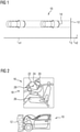
- FIG. 1 shows a schematic plan view of a motor vehicle 10 approaching an obstacle 12 which it is highly likely to collide with.
- the approximation process is shown in terms of time using a time axis with a time profile t, where t o defines an impact time, ie the time at which motor vehicle 10 and obstacle 12 touch.
- Motor vehicle 10 has a sensor 14 that detects a speed of motor vehicle 10 and a distance from obstacle 12 .
- the speed and the distance are parameters that are recorded in time before the expected impact and from which it is possible to calculate an expected course of the impact.
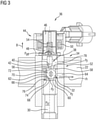
- FIG. 12 shows an interior (top) and an exterior (bottom) view of motor vehicle 10.
- FIG 1 as a snapshot at the time to of the impact.
- the interior view shows a snapshot of an activation of an airbag module 16 of an airbag system 18 in the motor vehicle 10 when, as in the exterior view of Motor vehicle 10 is shown, the motor vehicle 10 has crashed into the obstacle 12.
- an airbag sack 22 of the airbag module 16 is filled with an airbag gas 24, thereby unfolds and separates the occupant 20 from hard parts of the motor vehicle 10. Injuries to the occupant 20 can thereby be avoided.
- a further sensor 26 is arranged in the motor vehicle 10, which detects properties of the occupant 20, such as, for example, his size and his weight.
- a control device 28 detects signals from the sensors 14, 26 and uses these signals to determine the probable course of the impact. As a result, the control device 28 can define which mass flow m of the airbag gas 24 must be supplied to the airbag sack 22 .
- the airbag module 16 has a gas generator 30 which provides the airbag gas 24 for the airbag sack 22 .
- the airbag gas 24 is made available via a cold gas generator and is therefore present in gaseous form from the start.
- a pyrotechnic gas generator 30 is used, in the gas generator 30 is a solid propellant, which is first ignited to release the airbag gas 24 when needed.
- a gas supply 32 is arranged between the airbag sack 22 and the gas generator 28 , via which the airbag gas 24 can be conducted from the gas generator 30 to the airbag sack 22 .
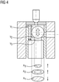
- a valve arrangement 34 is arranged in the gas feed line 32, which has an electrically controllable pilot valve 36, which can be controlled in a targeted manner via the control device 28 in such a way that the gas feed line 32 can be opened or closed in a targeted manner. In this way, a mass flow m of the airbag gas 24 fed from the gas generator 30 to the airbag sack 22 can be controlled in a targeted and predefined manner.
- the pilot valve 36 has a valve portion 38 where a pilot valve element 40 cooperates with a pilot valve seat 42 to hold the pilot valve 36 in a closed position.
- the pilot valve 36 also has an actuator area 44 which, in an electrically controlled state, exerts a motive force B on the pilot valve element 40, so that the pilot valve element 40 moves between its closed position and its open position.
- the actuator portion 44 includes magnetic elements such as a fixed pole piece 46 and a movable armature 48, with the armature 48 being coupled to the pilot valve member 40. As shown in FIG. As a result, the armature 48 transmits its movement to the pilot valve element 40. In order to induce the movement of the armature 48, the actuator area 44 includes a coil 50, which is energized for this purpose.
- the coil 50 forms a magnet with the magnetic elements of the pilot valve 36 .
- pilot valve element 40 closes the gas generator 30, so that a mass flow can occur simply by opening and closing the pilot valve element 40 ⁇ from the gas generator 30 to the airbag bag 22 can be regulated.
- the pilot valve 36 in 3 is designed as a normally closed pilot valve 36, ie in the de-energized state the pilot valve element 40 is in its closed position. For this purpose it is biased by a compression spring 54 in the direction of the closed position. In the closed position, the pilot valve element 40 closes an inlet bore 56 to the pilot valve 36, the inlet bore 56 forming the connection between the pilot valve 36 and the hydraulic transmission arrangement 52.
- the hydraulic transmission arrangement 52 is formed from a control chamber 58 which is fluidically connected to the gas generator 30 both via a connecting bore 60 and via a throttle bore 62 .
- the connecting bore 60 and the throttle bore 62 are bores which are arranged separately from one another and open into the control chamber 58 and into the gas generator 30 at different positions.
- the control chamber 58 is also fluidly connected to the pilot valve 36 via the inlet bore 56 .
- the control chamber 58 is fluidically connected to the airbag sack 22 via a drain hole 64 .
- a closing element 66 is arranged in the control chamber 58 and closes a valve seat 68 which is arranged in the connecting bore 60 in the first embodiment shown.
- the closing element 66 is designed as a separating element 70 and divides the control chamber 58 into a first control chamber region 52 and a second control chamber region 74, the two control chamber regions 72, 74 being separate from one another.
- the separating element 70 fluidly separates the two control chamber regions 72 , 74 from one another, but is nevertheless movably arranged within the control chamber 58 .
- the throttle bore 62 has an orifice 76 and fluidly connects the gas generator 30 to the first control chamber area 72.
- the pilot valve 36 is also fluidly connected to the first control chamber area 72 via the inlet bore 56.
- the connecting bore 60 fluidly connects the gas generator 30 to the second control chamber area 74.
- the closing element 66 is designed as a sphere on which a fluid pressure P F of the airbag gas 24 present in the respective control chamber region 72, 74 acts both from the side of the first control chamber region 72 and from the side of the second control chamber region 74.
- the first control chamber area 72 thereby forms a first volume V 1 in which the airbag gas 24 acts on the upper surface of the closure element 66 . This results in a relatively large first effective pressure area A 1 on the closing element 66 from the side of the first control chamber region 72 .
- the second control chamber area 74 forms a second volume V 2 with a corresponding second effective pressure area A 2 , which acts on the closing element 66 from the side of the second control chamber area 74 from below.
- the area in the connecting bore 60 that is closed by the closing element 66 forms a third volume V 3 with a corresponding third effective pressure area A 3 from below on the closing element 66.
- the second and third effective pressure areas A 2 and A 3 add up and act in opposition to the first effective pressure area A 1 .
- the action of the valve arrangement 34 which is used in the first embodiment in 3 and 4 shown is as follows:
- the hydraulic transmission arrangement 52 has the movable closing element 66 in the form of a ball and is controlled by the pilot valve 36 .
- the pilot valve 36 can, as in 3 shown, be normally closed, but it is also possible to use the pilot valve 36, as in figure 5 shown to provide as a normally open pilot valve 36.
- the selection of the type of pilot valve 36 depends on the safety concept of the airbag system 18.
- the pilot valve 36 closes the inlet bore 56 with the pilot valve element 40 without current being applied to the coil 50 by the compression spring 54.
- the compression spring 54 is clamped in a region between the armature 48 and the pole piece 46.
- a magnetic field and thereby a magnetic force is generated between the armature 48 and the pole piece 46, which acts against the force of the compression spring 54.
- the pilot valve 36 switches. The distance between the moving armature 48 and the fixed pole piece 46 is reduced and the pilot valve element 40 releases the cross-section of the inlet bore 56. This allows airbag gas 24 to flow through inlet bore 56 .
- the airbag gas 24 is discharged to the airbag sack 22 via a drain hole 78 of the pilot valve 36 .
- the hydraulic transmission arrangement 52 is designed as a seat valve. This means that the closing element 66 closes the valve seat 68 .
- the diameter of the valve seat 68 is smaller than the diameter of the closing element 66, since this is designed as a sphere.
- the third effective pressure area A 3 in the area of the connecting bore 60 is formed by the diameter of the valve seat 68 .
- the first effective pressure area A 1 in the first control chamber area 72 is determined by the outside diameter of the closing element 66 .
- the first effective pressure area A 1 in The first control chamber area 72 is larger than the third effective pressure area A 3 on the valve seat 68.
- the fluid pressure P F in the connecting bore 60 increases.
- the fluid pressure P F is thus present in the region of the valve seat 68 on the closing element 66 .
- the pilot valve 36 in the normally closed variant is closed.
- the airbag gas 24 can flow through the aperture 76 into the first control chamber region 72 as a result of the dynamic pressure.
- the fluid pressure P F in the first control chamber area 72 has equalized with the fluid pressure P F in the area of the valve seat 68 .
- the closing element 66 continues to close the connecting bore 60.
- the pilot valve 36 In order to meter an amount of gas from the airbag gas 24 to the outflow bore 64 and thus to the airbag sack 22 , the pilot valve 36 is supplied with current, as a result of which the pilot valve 36 releases the inflow bore 56 . As a result, the fluid pressure P F in the first control chamber area 52 drops, the closing element 66 switches and opens the cross section in the area of the valve seat 68 towards the outflow bore 64 . The mass flows m from the drain hole 64 and the drain hole 78 are collected and fed to the airbag sack 22 .
- a gas quantity of the airbag gas 24 can be supplied to the airbag sack 22 once or repeatedly.
- In 4 are the area ratios of the effective pressure areas A 1 , A 2 and A 3 in the detailed representation corresponding to the volumes V 1 , V 2 , V 3 are shown in the different areas of the control room 58 .
- the third effective pressure area A 3 acts within the seat diameter of the valve seat 68 on the closing element 66.
- a pressure from the outflow bore 64 acts on the airbag 22 or from the airbag sack 22 onto the lower second effective pressure area A 2 of the closing element 66.
- the second effective pressure area A 2 is located between the outer diameter of the closing element 66 and the seat diameter of the valve seat 68. The pressure in this area is much lower than in the connecting bore 60.
- the forces on the closure member 66 act in the same direction on the closure member 66.
- the corresponding first effective pressure area A 1 acts on the outer diameter of the closing element 66.
- the effective direction of the force on the closing element 66 is opposite to the forces on the effective pressure areas A 2 and A 3 . If there is a high pressure in the first control chamber area 72, the force on the first effective pressure area A 1 is greater than the sum of the forces on the effective pressure areas A 2 and A 3 .
- the closing element 66 closes and seals on the valve seat 68 . If there is a low pressure in the first control chamber area 72, the force on the first effective pressure area A 1 is smaller than the sum of the forces on the second and third effective pressure areas A 2 and A 3 .
- the closing element 66 opens and releases the connecting bore 60 and thus the flow to the airbag sack 22 via the drain bore 64 .
- valve assembly 34 In the longitudinal section in figure 5 is a function of the valve assembly 34 from 3 corresponding valve arrangement 34 is shown, the only difference being that the pilot valve 36 in 3 is designed as a normally closed pilot valve 36 and the pilot valve 36 in figure 5 as a normally open pilot valve 36.
- the components of the actuator area 44, in particular the pole piece 46, the armature 48 and the compression spring 54 are arranged accordingly.
- the compression spring 54 in 3 ensures that the pilot valve 36 is securely closed.
- an opening pressure P öff of the pilot valve 36 which is determined by the prestressing force of the compression spring 54, is above a high pressure P H of the airbag gas 24 in the gas generator 30, which is to be expected when the gas generator 30 is activated.
- a biasing force of the compression spring 54 is designed such that the pilot valve 36 is held in the open position, with the pilot valve element 40 assuming a defined open position.
- figs 6 , 7 and 8th show a second embodiment of the valve arrangement 34, wherein the pilot valve 36 or the entire actuator area 44 corresponds to the first embodiment in figs 3 to 5 is trained. Only the hydraulic transmission arrangement 52 differs in the second embodiment from that in the first embodiment.
- the effective pressure areas are A 1 , A 2 and A 3 , as in particular in FIG 7 can be seen, reversed compared to the first embodiment.
- the second effective pressure area A 2 between the outer diameter of the closing element 66 and the seat diameter of the valve seat 68 acts in the connecting bore 60 from the gas generator 30 Airbag sack 22 on the third effective pressure surface A 3 of the closing element 66.
- the second effective pressure surface A 2 is located between the outer diameter of the closing element 66 and the seat diameter of the valve seat 68.
- the fluid pressure P F in this area is much lower than in the connecting bore 60.
- the Forces on the closure member 66 act in the same direction on the closure member 66.
- the corresponding first effective pressure area A 1 acts on the outside diameter of the closing element 66.
- the effective direction of the fluid pressure P F on the first effective pressure surface A 1 is in the opposite direction to the force on the two effective pressure surfaces A 2 and A 3 . If there is a high fluid pressure P F in the first control chamber region 72, the force on the first effective pressure area A 1 is greater than the sum of the forces on the two effective pressure areas A 2 and A 3 .
- the closing element 66 closes and seals on the valve seat 68 . If there is a low fluid pressure P F in the first control chamber area 72, the force on the first effective pressure area A 1 is smaller than the sum of the forces on the two effective pressure areas A 2 and A 3 .
- the closing element 66 opens and allows flow to the airbag sack 22 .
- valve seat 68 on which the closing element 66 sits in the closed position is not formed on the connection hole 60 but on the drain hole 64 .
- valve assembly 34 in 6 differs from the valve assembly 34 in 8 only by the fact that the valve arrangement 34 in 6 a normally closed pilot valve 36 and the valve arrangement 34 in 8 has a normally open pilot valve 36 .
- valve arrangement 34 can be constructed in a very robust and compact manner, with the closing element 66 being of very simple design.
- the construction in the pilot-controlled design with the aid of the pilot valve 36 makes it possible to control large mass flows m with a relatively small pilot valve 36 .
- pilot valve 36 By exchanging the pilot valve 36 from a normally open design to a normally closed design, the use of the preloaded pilot valve element 40 and the pressure tap in front of the mass flow-limiting orifice 76, a variant constellation of different hydraulic transmission arrangements 52 corresponding to the safety concept of the airbag system 18 can be generated relatively easily.
Landscapes
- Engineering & Computer Science (AREA)
- Mechanical Engineering (AREA)
- Physics & Mathematics (AREA)
- Fluid Mechanics (AREA)
- Radar, Positioning & Navigation (AREA)
- Remote Sensing (AREA)
- General Engineering & Computer Science (AREA)
- Air Bags (AREA)
Description
- Die Erfindung betrifft ein Airbagmodul sowie ein Airbagsystem, die für gewöhnlich in Kraftfahrzeugen Teil eines Insassenrückhaltesystems bilden.
- Airbagsysteme bilden heutzutage gemeinsam mit Sicherheitsgurten die wichtigsten passiven Sicherheitselemente eines Insassenrückhaltesystems in einem Kraftfahrzeug, das schwerwiegenden Verletzungen bei einem Aufprall des Kraftfahrzeuges auf ein Hindernis entgegenwirken soll.
- Airbagsysteme weisen zumeist mehrere Airbagmodule auf, die jeweils wenigstens einen Airbagsack umfassen, der, wenn es zu einem Aufprall kommt, mit einem Airbaggas befüllt wird. Dabei entfaltet sich der Airbagsack innerhalb eines kurzen Zeitbereichs zwischen 10 ms und 50 ms zwischen einem Insassen und Teilen eines Innenraumes des Kraftfahrzeuges und bildet ein Kissen. Dadurch wird verhindert, dass der Insasse gegen harte Teile des Innenraumes wie beispielsweise ein Lenkrad oder Armaturenbrett prallt.
- Das Airbaggas wird in dem Gasgenerator mit einem Hochdruck zwischen 50 bar und 1000 bar bereitgestellt. Bei dem Gasgenerator kann es sich um einen Heißgasgenerator (pyrotechnischer Gasgenerator), einen Kaltgasgenerator oder auch um einen Hybridgasgenerator handeln.
- Airbagsysteme weisen weiter wenigstens einen Sensor auf, der im Falle eines Aufpralls einen Aufprallzeitpunkt to detektiert. Nach einer gewissen Zeit (ms-Bereich) nach diesem Aufprallzeitpunkt to wird die Airbagauslösung gestartet. Dazu weisen die Airbagmodule einen Gasgenerator auf, der das Airbaggas, mit dem der Airbagsack befüllt werden soll, bereitstellt. Das Airbaggas kann beispielsweise durch Zündung eines Festtreibstoffes, der bei Verbrennung das Airbaggas freisetzt, oder durch unter Hochdruck gespeichertes Gas bereitgestellt werden. Das Airbaggas aus dem Gasgenerator strömt in den Airbagsack, füllt diesen und sorgt für seine Entfaltung.
- Derzeit löst das Airbagsystem kurz nach dem Aufprallzeitpunkt to aus, d. h. erst wenn der Aufprall bereits erfolgt ist. Bei zukünftigen Airbagsystemen ist es jedoch geplant, durch geeignete Sensoren und Auswertung deren Signale einen Zeitpunkt tn zu erkennen, bei dem ein Aufprall unvermeidbar ist. Dieser Zeitpunkt tn liegt in der sog. Pre-Crash-Phase vor dem eigentlichen Zeitpunkt to des Aufpralls. Es ist geplant, mit dieser Information das Airbagsystem bereits vor dem Aufprall zu aktivieren, um so die Insassen eines Fahrzeuges noch besser vor Verletzungen schützen zu können.
- Bislang ist geplant, hierzu zweistufige Airbagmodule zu verwenden, bei denen zwei Gasgeneratoren vorgesehen sind, die zeitversetzt ausgelöst werden. Hier wird in zwei aufeinanderfolgenden Phasen je ein konstanter Massestrom m an Airbaggas in den Airbagsack eingeleitet.
- Ein Airbagmodul gemäß dem Oberbegriff des Anspruchs 1 ist aus der Offenlegungsschrift
DE 10 2012 210943 A1 bekannt. Ein weiteres Airbagmodul ist aus der OffenlegungsschriftWO 00/21799A1 - Aufgabe der Erfindung ist es, ein alteratives Airbagmodul für ein Airbagsystem vorzuschlagen.
- Diese Aufgabe wird mit einem Airbagmodul mit der Merkmalskombination des Anspruches 1 gelöst.
- Ein Airbagsystem, das ein solches Airbagmodul aufweist, ist Gegenstand des nebengeordneten Anspruches.
- Vorteilhafte Ausgestaltungen der Erfindung sind Gegenstand der abhängigen Ansprüche.
- Ein Airbagmodul weist einen Airbagsack, der im Betrieb mit einem druckbeaufschlagten Airbaggas befüllt wird, und einen Gasgenerator zum Bereitstellen des druckbeaufschlagten Airbaggases für den Airbagsack auf. Weiter weist das Airbagmodul eine Gaszuführung zwischen Gasgenerator und Airbagsack zum Zuführen des bereitgestellten druckbeaufschlagten Airbaggases von dem Gasgenerator in den Airbagsack auf. In der Gaszuführung ist eine Ventilanordnung zum Freigeben eines vordefinierten Massestroms m des druckbeaufschlagten Airbaggases aus dem Gasgenerator angeordnet.
- Der Massestrom m des Airbaggases ist dabei definiert durch die Masse, die pro Zeiteinheit zu dem Airbagsack hinströmt (m/t).
- Die Ventilanordnung weist ein elektrisch ansteuerbares Pilotventil zum Steuern des vordefinierten Massestroms m des Airbaggases und eine hydraulische Übersetzungsanordnung zur Vergrößerung einer Hubwirkung des Pilotventils auf.
- Dadurch, dass in der Gaszuführung zwischen dem Gasgenerator und dem Airbagsack eine gezielt elektrisch ansteuerbare Ventilanordnung vorgesehen ist, ist es möglich, die Füllung des Airbagsackes mit dem Airbaggas gezielt einem Aufprallverlauf anpassen zu können. Um einen optimalen Füllverlauf des Airbagsackes durchführen zu können, z. B. indem der Airbagsack bereits vor dem erwarteten Aufprall vollgefüllt und später noch nachgefüllt wird, ist eine Steuerung des Massestroms m des Airbaggases aus dem Gasgenerator erforderlich. Mit den bisher bekannten Airbagsystemen, bei denen zwei Gasgeneratoren zeitversetzt ausgelöst werden, ist es nur möglich, einen konstanten Massestrom m in dem Airbagsack zu erzeugen, eine gezielte Steuerung des Massestroms m ist jedoch nicht möglich. Dadurch, dass nur die Ventilanordnung mit dem elektrisch ansteuerbaren Pilotventil vorgesehen ist, kann zu jedem Zeitpunkt vor, während und nach dem Aufprall der Massestrom m über die Ventilanordnung gezielt gesteuert und somit die Befüllung des Airbagsackes zu jedem Zeitpunkt geregelt werden. So ist es möglich, die Füllung des Airbagsackes gezielt an den Aufprallverlauf anpassen zu können.
- Grundsätzlich wäre es beispielsweise bereits möglich, über ein einzelnes elektrisch ansteuerbares Ventil wie beispielsweise ein Magnetventil ein aktives Steuern der Befüllung des Airbagsackes zu ermöglichen. Wird jedoch ein Magnetventil verwendet, bewirkt die Größe und das Gewicht des verwendeten Magneten eine gewisse Trägheit des Systems und nimmt auch relativ viel Bauraum ein. Daher wird vorliegend lediglich ein kleines elektrisch ansteuerbares Pilotventil verwendet, das beispielsweise als Magnetventil ausgebildet sein kann. Hier ist nur ein kleiner Magnet notwendig, da zusätzlich zu dem Pilotventil selbst, das die eigentliche Steuerung des Massestroms m übernimmt, eine hydraulische Übersetzungsanordnung vorgesehen ist, die den eigentlichen Hub des Pilotventils vervielfacht. Dadurch ist es nicht nötig, einen sehr großen Magneten zu verwenden, sondern die gewünschte Masse wird durch die hydraulische Übersetzungsanordnung eingestellt, während die eigentliche Steuerung des Massestromes m über das elektrisch ansteuerbare Pilotventil erfolgt.
- Die hydraulische Übersetzungsanordnung weist einen Steuerraum auf, der fluidisch über eine Verbindungsbohrung und über eine getrennt von der Verbindungsbohrung angeordnete Drosselbohrung mit dem Gasgenerator verbunden ist. Weiter ist der steuerraum fluidisch über eine Ablaufbohrung mit dem Airbagsack verbunden. In dem Steuerraum ist ein Schließelement zum Verschließen und Freigeben eines Ventilsitzes in der Verbindungsbohrung oder in der Ablaufbohrung angeordnet. Das Schließelement ist dabei als Trennelement ausgebildet, das den Steuerraum in einen ersten Steuerraumbereich und in einem von dem ersten Steuerraumbereich getrennten zweiten Steuerraumbereich unterteilt.
- Das Schließelement ist als Trennelement zwischen dem ersten Steuerraumbereich und dem zweiten Steuerraumbereich angeordnet. Das bedeutet, dass ein statischer Fluiddruck sowohl von der Seite des ersten Steuerraumbereiches als auch von der Seite des zweiten Steuerraumbereiches auf das Schließelement wirkt. Ist das System druckausgeglichen, bewegt sich das Schließelement nicht, sondern bleibt in seiner Ausgangsposition stehen. Wirkt jedoch von der Seite des ersten Steuerraumbereiches ein anderer Druck als von der Seite des zweiten Steuerraumbereiches, bewegt sich das Schließelement - je nach Anordnung der beiden Steuerraumbereiche - in eine Öffnungs- bzw. Schließposition. In der Öffnungsposition gibt es die Gaszuführung frei, so dass Airbaggas von dem Gasgenerator in den Airbagsack strömen kann. In der Schließposition verschließt es jedoch die Gaszuführung, so dass kein Airbaggas von dem Gasgenerator in den Airbagsack strömt.
- Der von der Seite des ersten Steuerraumbereiches herrschende Fluiddruck wird durch das Pilotventil gesteuert. Dieses weist ein Pilotventilschließelement auf, das eine Zulaufbohrung zu dem Pilotventil verschließt. Über die Zulaufbohrung ist das Pilotventil vorteilhaft fluidisch mit dem Steuerraum verbunden, und zwar insbesondere mit dem ersten Steuerraumbereich. Öffnet sich das Pilotventil, kann Airbaggas aus dem ersten Steuerraumbereich über das Pilotventil abfließen, der Fluiddruck in dem ersten Steuerraumbereich sinkt, und ein Fluiddruck, der von dem zweiten Steuerraumbereich her auf das Schließelement wirkt, wird größer als der Fluiddruck, der von dem ersten Steuerraumbereich her auf das Schließelement wirkt. Das Schließelement verändert daher seine Position, insbesondere bewegt es sich in eine Öffnungsposition, und Airbaggas fließt von dem Gasgenerator in den Airbagsack.
- Das Pilotventil weist eine Ablaufbohrung auf, die eine fluidische Verbindung des Pilotventiles mit dem Airbagsack bildet. So fließt Airbaggas auch aus dem ersten Steuerraumbereich über die Zulaufbohrung und die Ablaufbohrung des Pilotventiles zu dem Airbagsack.
- Vorteilhaft verbindet die Drosselbohrung fluidisch den ersten Steuerraumbereich mit dem Gasgenerator, wobei das Pilotventil zum Steuern eines Fluiddruckes des Airbaggases in dem ersten Steuerraumbereich ausgebildet ist.
- Die Verbindungsbohrung, die den Gasgenerator mit dem Steuerraumbereich verbindet, verbindet den Gasgenerator insbesondere mit dem zweiten Steuerraumbereich.
- Das Schließelement ist vorteilhaft so ausgebildet, dass eine erste Druckwirkfläche auf das Schließelement von einer Seite des ersten Steuerraumbereiches größer ist als eine zweite Druckwirkfläche von einer Seite der Verbindungsbohrung, in der der Ventilsitz gebildet ist, oder von einer Seite der Ablaufbohrung, in der der Ventilsitz gebildet ist.
- Das Schließelement kann demgemäß so ausgebildet sein, dass es, wenn es sich in dem Ventilsitz befindet, die Ablaufbohrung zu dem Airbagsack hin verschließt, oder dass es die Verbindungsbohrung zwischen Steuerraum und Gasgenerator verschließt.
- Vorzugsweise ist das Schließelement als Kugel ausgebildet, es ist jedoch auch möglich, das Schließelement beispielsweise als Kegel auszubilden. Wichtig hierbei ist nur, dass sich die Druckwirkflächen von der Seite des ersten Steuerraumbereiches und von der Seite des zweiten Steuerraumbereiches unterscheiden, so dass eine Bewegung des Schließelementes durch eine Druckänderung in den beiden Steuerraumbereichen induziert werden kann.
- Über einen Durchmesser der Drosselbohrung ist es möglich, den in dem ersten Steuerraumbereich herrschenden Fluiddruck im Vergleich zu dem in dem zweiten Steuerraumbereich herrschenden Fluiddruck einzustellen. Es ist daher möglich, den Fluiddruck, der in dem ersten Steuerraumbereich herrscht, knapp unterhalb einem Schaltdruck, d. h. dem Zustand der Ventilanordnung, bei dem sich das Schließelement zu bewegen beginnt, oder knapp oberhalb des Schaltdruckes zu halten. Auch der Durchmesser der Zulaufbohrung zu dem Pilotventil kann in dieser Hinsicht angepasst werden, um einen Einfluss auf den herrschenden Fluiddruck zu bewirken.
- Vorzugsweise ist das Pilotventil als stromlos geschlossenes Pilotventil ausgebildet und weist eine Druckfeder auf, die ein Pilotventilelement in eine Schließposition auf einen Pilotventilsitz in der Zulaufbohrung vorspannt, wobei die Druckfeder einen Öffnungsdruck des Pilotventils insbesondere derart festlegt, dass der Öffnungsdruck größer ist als ein durch die Aktivierung des Gasgenerators im Gasgenerator herrschender Hochdruck des Airbaggases. So kann vorteilhaft vermieden werden, dass das Pilotventil ungewollt öffnet und somit die gesamte Ventilanordnung aktiviert.
- Alternativ ist es jedoch auch möglich, dass das Pilotventil als stromlos offenes Pilotventil ausgebildet ist. Dann wird durch Bestromung das Pilotventil aktiv geschlossen gehalten und nur durch Wegnahme des Stromes geöffnet. Vorteilhaft ist dazu eine Druckfeder vorgesehen, die das Pilotventil in eine definierte Öffnungsposition vorspannt.
- Ein Airbagsystem weist ein Airbagmodul wie oben beschrieben und weiter eine Steuereinrichtung zum Ansteuern des Pilotventils auf, wobei die Steuereinrichtung dazu ausgelegt ist, einen Aufprallverlauf zu erkennen und basierend auf dem erkannten Aufprallverlauf einen dem Airbagsack zuzuführenden Massestrom m des Airbaggases zu definieren.
- Vorteilhaft weist das Airbagsystem weiter wenigstens einen Sensor auf, der zeitlich vor einem Aufprall Parameter zum Berechnen eines voraussichtlichen Aufprallverlaufes erfasst und an die Steuereinrichtung überträgt.
- Vorzugsweise ist die Steuereinrichtung dazu ausgelegt, aus den erfassten Parametern den voraussichtlichen Aufprallverlauf und darauf basierend die zu jedem Zeitpunkt des Aufprallverlaufes benötigte Masse des Airbaggases in dem Airbagsack zu definieren.
- Über die erfassten Parameter des Sensors ist es daher möglich, zu erkennen, wann ein Aufprall unvermeidbar ist, wann beispielsweise der Aufprallzeitpunkt tn vorliegt, welche Kräfte beim Aufprall voraussichtlich wirken, und daraus zu schließen, in welchem Maße der Airbagsack aufgeblasen sein muss, um Verletzungen des Insassen zu vermeiden.
- Dazu ist es vorteilhaft, wenn nicht nur eine Geschwindigkeit des Fahrzeuges und ein Abstand zu einem Hindernis erfasst wird, sondern auch die Eigenschaften von Insassen, wie beispielsweise Größe und Gewicht, so dass die Aktivierung des Airbagsackes von Insassenparametern durchgeführt werden kann.
- Beispielsweise ist die Steuereinrichtung dazu ausgelegt, das Pilotventil derart anzusteuern, dass das Pilotventil mehrere definierte Teilmassen der benötigten Masse des Airbaggases zu unterschiedlichen Zeitpunkten des Aufprallverlaufes aus dem Gasgenerator freigibt. Beispielsweise kann das Pilotventil eine Teilmasse bereits vor dem erwarteten Aufprall in den Airbagsack freigeben, so dass dieser bereits vorbefüllt ist. Weiter ist es auch möglich, während des Aufpralls den Airbagsack mit einer weiteren Teilmasse zu füllen und auch nach dem eigentlichen Aufprall, wenn der Insasse aufgrund der Masseträgheit verzögert auf die negative Beschleunigung reagiert, den Airbagsack mit einer weiteren Teilmasse nachzufüllen.
- Vorteilhafte Ausgestaltungen der Erfindung werden nachfolgend anhand der beigefügten Zeichnungen näher erläutert. Darin zeigt:
- Fig. 1
- eine schematische Draufsicht auf ein Kraftfahrzeug, dass sich entlang einer Zeitachse t einem Hindernis nähert;
- Fig. 2
- eine Momentaufnahme zu einem Aufprallzeitpunkt to des Fahrzeuges aus
Fig. 1 auf das Hindernis, wenn ein Airbagmodul in einem Innenraum des Fahrzeuges aktiviert wird; - Fig. 3
- eine schematische Längsschnittdarstellung einer ersten Ausführungsform des Airbagmoduls aus
Fig. 2 mit einer Ventilanordnung, bei der ein Pilotventil als stromlos geschlossenes Pilotventil ausgebildet ist; - Fig. 4
- eine Detaildarstellung einer hydraulischen Übersetzungsanordnung für das Pilotventil aus
Fig. 3 ; - Fig. 5
- eine schematische Längsschnittdarstellung der Ventilanordnung aus
Fig. 3 , wobei das Pilotventil als stromlos offenes Pilotventil ausgebildet ist; - Fig. 6
- eine schematische Längsschnittdarstellung einer zweiten Ausführungsform des Airbagmoduls aus
Fig. 2 mit einer Ventilanordnung, bei der ein Pilotventil als stromlos geschlossenes Pilotventil ausgebildet ist; - Fig. 7
- eine Detaildarstellung einer hydraulischen Übersetzungsanordnung für das Pilotventil aus
Fig. 6 ; und - Fig. 8
- eine schematische Längsschnittdarstellung der Ventilanordnung aus
Fig. 6 , wobei das Pilotventil als stromlos offenes Pilotventil ausgebildet ist. -
Fig. 1 zeigt eine schematische Draufsicht auf ein Kraftfahrzeug 10, das sich einem Hindernis 12 nähert, auf das es mit hoher Wahrscheinlichkeit aufprallen wird. Der Näherungsvorgang ist zeitlich anhand einer Zeitachse mit einem Zeitverlauf t dargestellt, wobei to einen Aufprallzeitpunkt definiert, d. h. den Zeitpunkt, zu dem sich das Kraftfahrzeug 10 und das Hindernis 12 berühren. - Das Kraftfahrzeug 10 weist einen Sensor 14 auf, der eine Geschwindigkeit des Kraftfahrzeuges 10 und eine Entfernung zu dem Hindernis 12 erfasst. Die Geschwindigkeit und die Entfernung sind Parameter, die zeitlich vor dem voraussichtlichen Aufprall erfasst werden, und aus denen es möglich ist, einen voraussichtlich Aufprallverlauf zu berechnen.
-
Fig. 2 zeigt eine Innen- (oben) und eine Außenansicht (unten) des Kraftfahrzeuges 10 ausFig. 1 als Momentaufnahme zum Zeitpunkt to des Aufpralles. - In der Innenansicht ist eine Momentaufnahme einer Aktivierung eines Airbagmodules 16 eines Airbagsystems 18 in dem Kraftfahrzeug 10 zu sehen, wenn, wie in der Außenansicht des Kraftfahrzeuges 10 dargestellt ist, das Kraftfahrzeug 10 auf das Hindernis 12 aufgeprallt ist.
- Um einen Insassen 20 in dem Kraftfahrzeug 10 vor Verletzungen zu schützen, wird ein Airbagsack 22 des Airbagmoduls 16 mit einem Airbaggas 24 befüllt, entfaltet sich dadurch und trennt den Insassen 20 von harten Teilen des Kraftfahrzeuges 10. Dadurch können Verletzungen des Insassen 20 vermieden werden.
- In dem Kraftfahrzeug 10 ist ein weiterer Sensor 26 angeordnet, der Eigenschaften des Insassen 20 erfasst, wie beispielsweise seine Größe und sein Gewicht.
- Auf Basis der Parameter, die die Sensoren 14, 26 erfassen, ist es möglich, einen Aufprallverlauf des unvermeidbaren Aufpralles vorauszuberechnen, und zu ermitteln, zu welchen vorbestimmten Zeitpunkten tn der Airbagsack 22 wie stark aufgeblasen sein muss, um den Insassen 20 maximal schützen zu können.
- Eine Steuereinrichtung 28 erfasst dazu Signale der Sensoren 14, 26 und ermittelt aus diesen Signalen den voraussichtlichen Aufprallverlauf. Dadurch kann die Steuereinrichtung 28 definieren, welcher Massestrom m des Airbaggases 24 zu dem Airbagsack 22 zugeführt werden muss.
- Damit der Airbagsack 22 gezielt entsprechend des vorhergesagten Aufprallverlaufes gefüllt werden kann, ist ein spezielles, in den
Figs. 3 bis 8 in schematischer Längsschnittdarstellung gezeigtes Airbagmodul 16 vorgesehen. - Zunächst wird mit Bezug auf
Fig. 3 eine erste Ausführungsform des Airbagmodules 16 beschrieben. Das Airbagmodul 16 weist neben dem Airbagsack 22 einen Gasgenerator 30 auf, der das Airbaggas 24 für den Airbagsack 22 bereitstellt. Hierbei besteht die Möglichkeit, dass das Airbaggas 24 über einen Kaltgasgenerator zur Verfügung gestellt wird und somit von Anfang an in gasförmiger Form vorliegt. Es ist jedoch auch möglich, dass ein pyrotechnischer Gasgenerator 30 verwendet wird, wobei sich in dem Gasgenerator 30 ein Festtreibstoff befindet, der zunächst entzündet wird, um das Airbaggas 24 im benötigten Fall freizusetzen. - Zwischen dem Airbagsack 22 und dem Gasgenerator 28 ist eine Gaszuführung 32 angeordnet, über die das Airbaggas 24 von dem Gasgenerator 30 zu dem Airbagsack 22 geleitet werden kann.
- In der Gaszuführung 32 ist eine Ventilanordnung 34 angeordnet, die ein elektrisch ansteuerbares Pilotventil 36 aufweist, das gezielt so über die Steuereinrichtung 28 ansteuerbar ist, dass die Gaszuführung 32 gezielt geöffnet bzw. verschlossen werden kann. So kann ein von dem Gasgenerator 30 zu dem Airbagsack 22 zugeführter Massestrom m des Airbaggases 24 gezielt und vordefiniert gesteuert werden.
- Das Pilotventil 36 weist einen Ventilbereich 38 auf, bei dem ein Pilotventilelement 40 mit einem Pilotventilsitz 42 zusammenwirkt, um das Pilotventil 36 in einer Schließposition zu halten.
- Das Pilotventil 36 weist weiter einen Aktorbereich 44 auf, der in einem elektrisch angesteuerten Zustand eine Bewegungskraft B auf das Pilotventilelement 40 ausübt, so dass sich das Pilotventilelement 40 zwischen seiner Schließposition und seiner Öffnungsposition bewegt.
- Der Aktorbereich 44 weist magnetische Elemente wie ein feststehendes Polstück 46 und einen beweglichen Anker 48 auf, wobei der Anker 48 mit dem Pilotventilelement 40 gekoppelt ist. Dadurch überträgt der Anker 48 seine Bewegung auf das Pilotventilelement 40. Um die Bewegung des Ankers 48 zu induzieren, umfasst der Aktorbereich 44 eine Spule 50, die hierfür bestromt wird.
- Die Spule 50 bildet mit den magnetischen Elementen des Pilotventiles 36 einen Magneten aus.
- Normalerweise würde es ausreichen, wenn das Pilotventilelement 40 den Gasgenerator 30 verschließt, so dass durch einfaches Öffnen und Schließen des Pilotventilelementes 40 ein Massestrom ṁ von dem Gasgenerator 30 zu dem Airbagsack 22 geregelt werden kann.
- Hierzu ist jedoch ein relativ großer Magnet nötig, der einen relativ großen Bauraum in dem Airbagmodul 16 benötigt und außerdem auch verhältnismäßig träge ist.
- Daher wird nun in den nachfolgend beschriebenen Ausführungsformen vorgeschlagen, zwischen dem Gasgenerator 30 und dem Pilotventil 36 eine hydraulische Übersetzung 52 zwischenzuschalten, die einen Hub des Pilotventilelementes 40 verstärkt. Dadurch kann das Pilotventil 36 und somit auch die Magnetanordnung deutlich kleiner ausgebildet sein, benötigt daher weniger Bauraum und kann sehr schnell schalten.
- Das Pilotventil 36 in
Fig. 3 ist als stromlos geschlossenes Pilotventil 36 ausgebildet, d. h., im unbestromten Zustand befindet sich das Pilotventilelement 40 in seiner Schließposition. Dazu wird es von einer Druckfeder 54 in Richtung auf die Schließposition vorgespannt. In der Schließposition verschließt das Pilotventilelement 40 eine Zulaufbohrung 56 zu dem Pilotventil 36, wobei die Zulaufbohrung 56 die Verbindung des Pilotventiles 36 zu der hydraulischen Übersetzungsanordnung 52 bildet. - Die hydraulische Übersetzungsanordnung 52 ist gebildet aus einem Steuerraum 58, der fluidisch sowohl über eine Verbindungsbohrung 60 als auch über eine Drosselbohrung 62 mit dem Gasgenerator 30 verbunden ist. Die Verbindungsbohrung 60 und die Drosselbohrung 62 sind getrennt voneinander angeordnete Bohrungen, die an unterschiedlichen Positionen in den Steuerraum 58 bzw. in den Gasgenerator 30 münden. Der Steuerraum 58 ist über die Zulaufbohrung 56 auch fluidisch mit dem Pilotventil 36 verbunden. Weiter ist der Steuerraum 58 fluidisch über eine Ablaufbohrung 64 mit dem Airbagsack 22 verbunden. In dem Steuerraum 58 ist ein Schließelement 66 angeordnet, das einen Ventilsitz 68 verschließt, der in der gezeigten ersten Ausführungsform in der Verbindungsbohrung 60 angeordnet ist. Das Schließelement 66 ist als Trennelement 70 ausgebildet und unterteilt den Steuerraum 58 in einen ersten Steuerraumbereich 52 und einen zweiten Steuerraumbereich 74, wobei die beiden Steuerraumbereiche 72, 74 getrennt voneinander sind. Das Trennelement 70 trennt die beiden Steuerraumbereiche 72, 74 fluidisch voneinander ab, ist aber dennoch innerhalb des Steuerraumes 58 beweglich angeordnet.
- Die Drosselbohrung 62 weist eine Blende 76 auf und verbindet den Gasgenerator 30 fluidisch mit dem ersten Steuerraumbereich 72. Auch das Pilotventil 36 ist über die Zulaufbohrung 56 mit dem ersten Steuerraumbereich 72 fluidisch verbunden.
- Die Verbindungsbohrung 60 verbindet den Gasgenerator 30 fluidisch mit dem zweiten Steuerraumbereich 74.
- Das Schließelement 66 ist in der vorliegenden Ausführungsform als Kugel ausgebildet, auf die sowohl von der Seite des ersten Steuerraumbereiches 72 als auch von der Seite des zweiten Steuerraumbereiches 74 ein Fluiddruck PF des in dem jeweiligen Steuerraumbereich 72, 74 vorhandenen Airbaggases 24 wirkt.
- Dies ist in einer Detaildarstellung in
Fig. 4 gezeigt. Der erste Steuerraumbereich 72 bildet dabei ein erstes Volumen V1, in dem das Airbaggas 24 auf die obere Fläche des Schließelementes 66 wirkt. Dadurch entsteht eine relativ große erste Druckwirkfläche A1 auf das Schließelement 66 von Seite des ersten Steuerraumbereiches 72 her. - Der zweite Steuerraumbereich 74 bildet ein zweites Volumen V2 mit einer entsprechenden zweiten Druckwirkfläche A2, die von Seite des zweiten Steuerraumbereiches 74 auf das Schließelement 66 von unten wirkt. Zusätzlich bildet der Bereich in der Verbindungsbohrung 60, die mit dem Schließelement 66 verschlossen wird, ein drittes Volumen V3 mit einer entsprechenden dritten Druckwirkfläche A3 von unten auf das Schließelement 66.
- Die zweite und dritte Druckwirkfläche A2 und A3 addieren sich und wirken entgegen der ersten Druckwirkfläche A1.
- Die Wirkung der Ventilanordnung 34, die in der ersten Ausführungsform in
Fig. 3 undFig. 4 gezeigt ist, ist wie folgt:
Die hydraulische Übersetzungsanordnung 52 weist das bewegliche Schließelement 66 in Form einer Kugel auf und wird durch das Pilotventil 36 angesteuert. Das Pilotventil 36 kann, wie inFig. 3 gezeigt, stromlos geschlossen sein, es ist jedoch auch möglich, das Pilotventil 36, wie inFig. 5 gezeigt, als stromlos offenes Pilotventil 36 vorzusehen. Die Wahl des Typs des Pilotventiles 36 ist abhängig vom Sicherheitskonzept des Airbagsystems 18. - Bei der stromlos geschlossenen Variante in
Fig. 3 verschließt das Pilotventil 36 ohne Strombeaufschlagung der Spule 50 mit dem Pilotventilelement 40 die Zulaufbohrung 56 durch die Druckfeder 54. Die Druckfeder 54 ist in einem Bereich zwischen dem Anker 48 und dem Polstück 46 eingespannt. Bei einer Strombeaufschlagung der Spule 50 wird ein Magnetfeld und dadurch eine Magnetkraft zwischen dem Anker 48 und dem Polstück 46 erzeugt, die gegen die Kraft der Druckfeder 54 wirkt. Zu dem Zeitpunkt, zu dem die Kraft der Druckfeder 54 von der Magnetkraft zwischen dem beweglichen Anker 48 und dem feststehenden Polstück 46 überwunden wird, schaltet das Pilotventil 36. Der Abstand zwischen dem beweglichen Anker 48 und dem feststehenden Polstück 46 wird verringert und das Pilotventilelement 40 gibt den Querschnitt der Zulaufbohrung 56 frei. Dadurch kann das Airbaggas 24 durch die Zulaufbohrung 56 fließen. Das Airbaggas 24 wird über eine Ablaufbohrung 78 des Pilotventiles 36 zu dem Airbagsack 22 abgeleitet. - Die hydraulische Übersetzungsanordnung 52 ist als Sitzventil ausgeführt. Das bedeutet, dass das Schließelement 66 den Ventilsitz 68 verschließt. Der Durchmesser des Ventilsitzes 68 ist kleiner als der Durchmesser des Schließelementes 66, da dieses als Kugel ausgebildet ist. Die dritte Druckwirkfläche A3 im Bereich der Verbindungsbohrung 60 wird durch den Durchmesser des Ventilsitzes 68 gebildet. Die erste Druckwirkfläche A1 im ersten Steuerraumbereich 72 wird durch den Außendurchmesser des Schließelementes 66 bestimmt. Die erste Druckwirkfläche A1 im ersten Steuerraumbereich 72 ist größer als die dritte Druckwirkfläche A3 am Ventilsitz 68. Wird daher das Schließelement 66 von beiden Seiten mit dem gleichen Fluiddruck PF beaufschlagt, wirkt vom ersten Steuerraumbereich 72 durch die größere erste Druckwirkfläche A1 eine größere Kraft als aus dem Bereich des Ventilsitzes 68 entgegen. Dadurch schließt das Schließelement 66 und liegt an dem Ventilsitz 68 an.
- Nach Aktivierung des Gasgenerators 30 steigt der Fluiddruck PF in der Verbindungsbohrung 60. Der Fluiddruck PF steht damit im Bereich des Ventilsitzes 68 an dem Schließelement 66 an. Das Pilotventil 36 in der stromlos geschlossenen Variante ist geschlossen. Durch den Staudruck kann Airbaggas 24 durch die Blende 76 in den ersten Steuerraumbereich 72 fließen. Nach kurzer Zeit hat sich der Fluiddruck PF in dem ersten Steuerraumbereich 72 mit dem Fluiddruck PF im Bereich des Ventilsitzes 68 ausgeglichen. Das Schließelement 66 verschließt weiterhin die Verbindungsbohrung 60.
- Um eine Gasmenge des Airbaggases 24 zu der Ablaufbohrung 64 und somit zu dem Airbagsack 22 zuzudosieren, wird das Pilotventil 36 mit Strom beaufschlagt, wodurch das Pilotventil 36 die Zulaufbohrung 56 freigibt. Dadurch fällt der Fluiddruck PF in dem ersten Steuerraumbereich 52 ab, das Schließelement 66 schaltet und gibt den Querschnitt im Bereich des Ventilsitzes 68 zu der Ablaufbohrung 64 hin frei. Die Masseströme m aus der Ablaufbohrung 64 und der Ablaufbohrung 78 werden gesammelt und zu dem Airbagsack 22 zugeführt.
- Um den Massestrom m des Airbaggases 24 zu dem Airbagsack 22 zu stoppen, wird das Pilotventil 36 wieder geschlossen.
- Durch die Ansteuerung des Pilotventils 36 kann einmalig oder auch wiederholt eine Gasmenge des Airbaggases 24 dem Airbagsack 22 zugeführt werden.
- In
Fig. 4 sind in der Detaildarstellung die Flächenverhältnisse der Druckwirkflächen A1, A2 und A3 entsprechend zu den Volumina V1, V2, V3 in den unterschiedlichen Bereichen des Steuerraumes 58 dargestellt. In der Verbindungsbohrung 60 aus dem Gasgenerator 30 wirkt die dritte Druckwirkfläche A3 innerhalb des Sitzdurchmessers des Ventilsitzes 68 auf das Schließelement 66. In dem zweiten Steuerraumbereich 74, d. h. in dem zweiten Volumen V2, wirkt ein Druck aus der Ablaufbohrung 64 zu dem Aibagsack 22 bzw. aus dem Airbagsack 22 auf die untere zweite Druckwirkfläche A2 des Schließelementes 66. Die zweite Druckwirkfläche A2 befindet sich zwischen dem Außendurchmesser des Schließelementes 66 und dem Sitzdurchmesser des Ventilsitzes 68. Der Druck in diesem Bereich ist sehr viel geringer als in der Verbindungsbohrung 60. Die Kräfte auf das Schließelement 66 wirken in die gleiche Richtung auf das Schließelement 66. - In dem ersten Steuerraumbereich 72 wirkt die entsprechende erste Druckwirkfläche A1 auf den Außendurchmesser des Schließelementes 66. Die Wirkrichtung der Kraft auf das Schließelement 66 ist den Kräften auf die Druckwirkflächen A2 und A3 entgegengerichtet. Herrscht in dem ersten Steuerraumbereich 72 ein hoher Druck, ist die Kraft auf die erste Druckwirkfläche A1 größer als die Summe der Kräfte auf die Druckwirkflächen A2 und A3. Das Schließelement 66 schließt und dichtet auf den Ventilsitz 68 ab. Herrscht in dem ersten Steuerraumbereich 72 ein niedriger Druck, ist die Kraft auf die erste Druckwirkfläche A1 kleiner als die Summe der Kräfte auf die zweite und dritte Druckwirkfläche A2 und A3. Das Schließelement 66 öffnet und gibt die Verbindungsbohrung 60 und somit den Durchfluss zu dem Airbagsack 22 über die Ablaufbohrung 64 frei.
- In der Längsschnittdarstellung in
Fig. 5 ist eine in ihrer Wirkungsweise der Ventilanordnung 34 ausFig. 3 entsprechende Ventilanordnung 34 gezeigt, wobei der Unterschied lediglich darin besteht, dass das Pilotventil 36 inFig. 3 als stromlos geschlossenes Pilotventil 36 ausgebildet ist und das Pilotventil 36 inFig. 5 als stromlos offenes Pilotventil 36. Dazu sind die Bauteile des Aktorbereichs 44, insbesondere das Polstück 46, der Anker 48 und die Druckfeder 54 entsprechend angeordnet. - Die Druckfeder 54 in
Fig. 3 sorgt dafür, dass das Pilotventil 36 sicher geschlossen ist. Dazu liegt ein Öffnungsdruck Pöff des Pilotventiles 36, der durch die Vorspannkraft der Druckfeder 54 bestimmt wird, oberhalb eines Hochdruckes PH des Airbaggases 24 in dem Gasgenerator 30, der bei Aktivieren des Gasgenerators 30 zu erwarten ist. - Bei dem Pilotventil 36 in
Fig. 5 ist eine Vorspannkraft der Druckfeder 54 so ausgelegt, dass das Pilotventil 36 in der Öffnungsposition gehalten wird, wobei das Pilotventilelement 40 eine definierte Öffnungsposition einnimmt. -
Figs. 6 ,7 und8 zeigen eine zweite Ausführungsform der Ventilanordnung 34, wobei das Pilotventil 36 bzw. der gesamte Aktorbereich 44 entsprechend der ersten Ausführungsform inFigs. 3 bis 5 ausgebildet ist. Lediglich die hydraulische Übersetzungsanordnung 52 unterscheidet sich in der zweiten Ausführungsform von der in der ersten Ausführungsform. - Bei der zweiten Ausführungsform sind die Druckwirkflächen A1, A2 und A3, wie insbesondere in
Fig. 7 zu sehen ist, im Vergleich zu der ersten Ausführungsform vertauscht. Dabei wirkt in der Verbindungsbohrung 60 aus dem Gasgenerator 30 die zweite Druckwirkfläche A2 zwischen dem Außendurchmesser des Schließelementes 66 und dem Sitzdurchmesser des Ventilsitzes 68. Im Bereich des dritten Volumens V3 wirkt der Druck aus der Ablaufbohrung 64 zu dem Airbagsack 22 bzw. aus dem Airbagsack 22 auf die dritte Druckwirkfläche A3 des Schließelementes 66. Die zweite Durckwirkfläche A2 befindet sich zwischen dem Außendurchmesser des Schließelementes 66 und dem Sitzdurchmesser des Ventilsitzes 68. Der Fluiddruck PF in diesem Bereich ist sehr viel geringer als in der Verbindungsbohrung 60. Die Kräfte auf das Schließelement 66 wirken in die gleiche Richtung auf das Schließelement 66. - In dem ersten Steuerraumbereich 72 wirkt die entsprechende erste Druckwirkfläche A1 auf den Außendurchmesser des Schließelementes 66. Die Wirkrichtung des Fluiddruckes PF auf die erste Druckwirkfläche A1 ist der Kraft auf die beiden Druckwirkflächen A2 und A3 entgegengerichtet. Herrscht in dem ersten Steuerraumbereich 72 ein hoher Fluiddruck PF, ist die Kraft auf die erste Druckwirkfläche A1 größer als die Summe der Kräfte auf die beiden Druckwirkflächen A2 und A3. Das Schließelement 66 schließt und dichtet auf den Ventilsitz 68 ab. Herrscht in dem ersten Steuerraumbereich 72 ein niedriger Fluiddruck PF, ist die Kraft auf die erste Druckwirkfläche A1 kleiner als die Summe der Kräfte auf die beiden Druckwirkflächen A2 und A3. Das Schließelement 66 öffnet und gibt den Durchfluss zu dem Airbagsack 22 frei.
- In der zweiten Ausführungsform in der Ventilsitz 68, auf dem das Schließelement 66 in der Schließposition sitzt, nicht an der Verbindungsbohrung 60, sondern an der Ablaufbohrung 64 gebildet.
- Die Ventilanordnung 34 in
Fig. 6 unterscheidet sich von der Ventilanordnung 34 inFig. 8 lediglich dadurch, dass die Ventilanordnung 34 inFig. 6 ein stromlos geschlossenes Pilotventil 36 und die Ventilanordnung 34 inFig. 8 ein stromlos offenes Pilotventil 36 aufweist. - Die oben beschriebenen Ausführungsformen haben den Vorteil, dass die gesamte Ventilanordnung 34 jeweils sehr robust und kompakt aufgebaut werden kann, wobei das Schließelement 66 sehr einfach ausgebildet ist. Durch den Aufbau in der vorgesteuerten Bauform mit Hilfe des Pilotventiles 36 ist es möglich, mit einem relativ kleinen Pilotventil 36 große Masseströme m zu steuern. Durch einen Austausch des Pilotventiles 36 von einer stromlos geöffneten Bauform zu einer stromlos geschlossenen Bauform, dem Einsatz des vorgespannten Pilotventilelementes 40 und dem Druckabgriff vor der massestromlimitierenden Blende 76 kann relativ einfach eine Variantenkonstellation von unterschiedlichen hydraulischen Übersetzungsanordnungen 52 entsprechend dem Sicherheitskonzept des Airbagsystems 18 erzeugt werden.
Claims (7)
- Airbagmodul (16), aufweisend:- einen Airbagsack (22), der im Betrieb mit einem druckbeaufschlagten Airbaggas (24) befüllt wird;- einen Gasgenerator (30) zum Bereitstellen des druckbeaufschlagten Airbaggases (24); und- eine Gaszuführung (32) zwischen Gasgenerator (30) und Airbagsack (22) zum Zuführen des bereitgestellten druckbeaufschlagten Airbaggases (24) von dem Gasgenerator (30) in den Airbagsack (22);wobei in der Gaszuführung (32) eine Ventilanordnung (34) zum Freigeben eines vordefinierten Massestroms (m) des druckbeaufschlagten Airbaggases (24) aus dem Gasgenerator (30) angeordnet ist,wobei die Ventilanordnung (34) ein elektrisch ansteuerbares Pilotventil (36) zum Steuern des vordefinierten Massestroms (m) des Airbaggases (24) und eine hydraulische Übersetzungsanordnung (52) zur Vergrößerung einer Hubwirkung des Pilotventils (36) aufweist, wobei die hydraulische Übersetzungsanordnung (52) einen Steuerraum (58) aufweist, der fluidisch über eine Verbindungsbohrung (60) und über eine getrennt von der Verbindungsbohrung (60) angeordnete Drosselbohrung (62) mit dem Gasgenerator (30) verbunden ist, und der fluidisch über eine Ablaufbohrung (64) mit dem Airbagsack (22) verbunden ist, dadurch gekennzeichnet, dass in dem Steuerraum (58) ein Schließelement (66) zum Verschließen und Freigeben eines Ventilsitzes (68) in der Verbindungsbohrung (60) oder in der Ablaufbohrung (64) angeordnet ist, wobei das Schließelement (66) als Trennelement (70) ausgebildet ist, das den Steuerraum (58) in einen ersten Steuerraumbereich (72) und in einen von dem ersten Steuerraum (58) getrennten zweiten Steuerraumbereich (74) unterteilt,wobei eine Zulaufbohrung (56) zu dem Pilotventil (36) eine fluidische Verbindung des Steuerraumes (58) zu dem Pilotventils (36) bildet,und wobei eine Ablaufbohrung (78) des Pilotventiles eine fluidische Verbindung des Pilotventiles (36) mit dem Airbagsack (22) bildet.
- Airbagmodul (16) nach Anspruch 1,
dadurch gekennzeichnet, dass die Drosselbohrung (62) fluidisch den ersten Steuerraumbereich (72) mit dem Gasgenerator (30) verbindet, wobei das Pilotventil (36) zum Steuern eines Fluiddruckes (PF) des Airbaggases (24) in dem ersten Steuerraumbereich (72) ausgebildet ist. - Airbagmodul (16) nach einem der Ansprüche 1 bis 2, dadurch gekennzeichnet, dass die Verbindungsbohrung (60) den Gasgenerator (30) mit dem zweitem Steuerraumbereich (74) verbindet.
- Airbagmodul (16) nach einem der Ansprüche 1 bis 3, dadurch gekennzeichnet, dass das Schließelement (66) so ausgebildet ist, dass eine erste Druckwirkfläche (A1) auf das Schließelement (66) von einer Seite des ersten Steuerraumbereichs (72) größer ist als eine zweite Druckwirkfläche (A2) von einer Seite der Verbindungsbohrung (60), in der der Ventilsitz (68) gebildet ist, oder von einer Seite der Ablaufbohrung (64), in der der Ventilsitz (68) gebildet ist.
- Airbagmodul (16) nach einem der Ansprüche 1 bis 4, dadurch gekennzeichnet, dass das Pilotventil (36) als stromlos geschlossenes Pilotventil (36) ausgebildet ist und eine Druckfeder (54) aufweist, die ein Pilotventilelement (40) in eine Schließposition (66) auf einen Pilotventilsitz (42) in der Zulaufbohrung (56) vorspannt, wobei die Druckfeder (54) einen Öffnungsdruck (Pöff) des Pilotventils (36) insbesondere derart festlegt, dass der Öffnungsdruck (Pöff) größer ist als ein durch die Aktivierung des Gasgenerators (30) im Gasgenerator (30) herrschender Hochdruck (PH) des Airbaggases (24).
- Airbagmodul (16) nach einem der Ansprüche 1 bis 4, dadurch gekennzeichnet, dass das Pilotventil (36) als stromlos offenes Pilotventil (36) ausgebildet ist und eine Druckfeder (54) aufweist, die das Pilotventilelement (40) in eine definierte Öffnungsposition vorspannt.
- Airbagsystem (18), aufweisend:- ein Airbagmodul (16) nach einem der Ansprüche 1 bis 6; und- eine Steuereinrichtung (28) zum Ansteuern des Pilotventils (36), wobei die Steuereinrichtung (28) dazu ausgelegt ist, einen Aufprallverlauf zu erkennen und basierend auf dem erkannten Aufprallverlauf einen dem Airbagsack (22) zuzuführenden Massestrom (m) des Airbaggases (24) zu definieren.
Applications Claiming Priority (2)
| Application Number | Priority Date | Filing Date | Title |
|---|---|---|---|
| DE102018204825.8A DE102018204825A1 (de) | 2018-03-29 | 2018-03-29 | Airbagmodul und Airbagsystem |
| PCT/EP2019/057144 WO2019185451A1 (de) | 2018-03-29 | 2019-03-21 | Airbagmodul und airbagsystem |
Publications (3)
| Publication Number | Publication Date |
|---|---|
| EP3774454A1 EP3774454A1 (de) | 2021-02-17 |
| EP3774454B1 true EP3774454B1 (de) | 2022-03-09 |
| EP3774454B8 EP3774454B8 (de) | 2022-07-20 |
Family
ID=65904435
Family Applications (1)
| Application Number | Title | Priority Date | Filing Date |
|---|---|---|---|
| EP19712994.3A Active EP3774454B8 (de) | 2018-03-29 | 2019-03-21 | Airbagmodul und airbagsystem |
Country Status (5)
| Country | Link |
|---|---|
| US (1) | US11338752B2 (de) |
| EP (1) | EP3774454B8 (de) |
| CN (1) | CN111556828B (de) |
| DE (2) | DE102018204825A1 (de) |
| WO (1) | WO2019185451A1 (de) |
Families Citing this family (3)
| Publication number | Priority date | Publication date | Assignee | Title |
|---|---|---|---|---|
| US10160417B2 (en) * | 2017-04-20 | 2018-12-25 | Ford Global Technologies, Llc | Rotatably supported airbag |
| DE102018202722A1 (de) * | 2018-02-22 | 2019-08-22 | Continental Automotive Gmbh | Ventil für ein Airbagsystem für ein Kraftfahrzeug und Airbagsystem für ein Kraftfahrzeug |
| DE102019210802A1 (de) | 2019-07-22 | 2021-01-28 | Continental Automotive Gmbh | Steuervorrichtung für einen Gasgenerator zum Steuern eines Volumenstroms sowie Aufprallschutzsystem und Verfahren zum Betreiben einer solchen Steuervorrichtung |
Family Cites Families (36)
| Publication number | Priority date | Publication date | Assignee | Title |
|---|---|---|---|---|
| US2834609A (en) * | 1956-11-05 | 1958-05-13 | Harry A Bertrand | Passenger safety device for vehicles |
| CA964693A (en) * | 1971-06-10 | 1975-03-18 | David P. Hass | Safety apparatus |
| US5074583A (en) * | 1988-07-29 | 1991-12-24 | Mazda Motor Corporation | Air bag system for automobile |
| DE4028715A1 (de) * | 1990-04-09 | 1991-10-10 | Alfred Kroiss | Gaskissen-aufprallschutzvorrichtung |
| US6899134B2 (en) * | 2001-10-23 | 2005-05-31 | Automotive Technologies International, Inc. | Discharge valves for airbags and airbags including the same |
| US5709405A (en) * | 1996-04-10 | 1998-01-20 | Morton International, Inc. | Variable mass flow airbag module |
| US5871231A (en) * | 1996-06-05 | 1999-02-16 | Simula Inc. | Low aggressivity variable-volume variable-inflation air bag system |
| US5947514A (en) | 1998-02-20 | 1999-09-07 | Breed Automotive Technology, Inc. | Valve controlled automotive pyrotechnic systems |
| US6068288A (en) * | 1998-03-26 | 2000-05-30 | Sturman/Tlx Llc | Dynamic control valve system adapted for inflatable restraint systems for vehicles |
| US6176518B1 (en) * | 1998-10-02 | 2001-01-23 | Trw Vehicle Safety Systems Inc. | Inflator with temperature responsive valve |
| AU1312900A (en) | 1998-10-09 | 2000-05-01 | Airbelt Systems, Llc. | Flow regulated inflator |
| DE10016516A1 (de) * | 2000-04-03 | 2001-10-18 | Autoliv Dev | Gasleitgehäuse einer Gassackanordnung mit Aufblas-Steuerung |
| US6616177B2 (en) * | 2001-06-11 | 2003-09-09 | General Motors Corporation | Dual depth airbag |
| RU2206467C2 (ru) * | 2001-07-13 | 2003-06-20 | Исаков Сергей Николаевич | Способ приведения в состояние готовности надувной оболочки устройства безопасности, типа надувной подушки безопасности (варианты), устройство безопасности для транспортного средства (варианты), клапанное устройство |
| DE102004009300A1 (de) * | 2004-02-26 | 2005-09-15 | Robert Bosch Gmbh | Insassenschutzvorrichtung |
| JP4734933B2 (ja) * | 2004-02-27 | 2011-07-27 | タカタ株式会社 | 車両乗員保護システムおよびインフレータ |
| DE202004015166U1 (de) * | 2004-09-29 | 2005-02-10 | Trw Automotive Safety Systems Gmbh | Gassackmodul |
| US7967393B2 (en) * | 2004-10-04 | 2011-06-28 | Kelsey-Hayes Company | Pressure balanced supply valve for vehicle brake system with integrated low pressure accumulator |
| US7591481B2 (en) * | 2005-05-27 | 2009-09-22 | Authomotive Systems Laboratory, Inc. | Vehicle occupant protection system |
| DE102005031545B4 (de) * | 2005-07-06 | 2007-09-27 | Autoliv Development Ab | Seitengassack-Einheit für ein Kraftfahrzeug |
| US20070181030A1 (en) * | 2005-10-09 | 2007-08-09 | Haim Goldenblum | Accident prevent launcher |
| FR2896833B1 (fr) * | 2006-01-30 | 2008-04-04 | Coval Soc Par Actions Simplifi | Dispositif de commande d'un circuit consommateur de gaz comprime et generateur de vide faisant application |
| US7469926B2 (en) * | 2006-05-19 | 2008-12-30 | Autoliv Asp, Inc. | Active venting inflator device |
| US7464961B2 (en) * | 2006-06-14 | 2008-12-16 | Island Pyrochemical Industries Corp. | Variable output inflator |
| US7748737B2 (en) * | 2007-01-16 | 2010-07-06 | Ford Global Technologies, Llc | Variable output inflator |
| DE102007003321A1 (de) * | 2007-01-17 | 2008-08-21 | Mbb International Group Ag | Verschlusseinrichtung für einen mit Druckgas befüllbaren Druckbehälter eines Kaltgasgenerators |
| US7721915B2 (en) * | 2007-04-11 | 2010-05-25 | Goodrich Corporation | Hybrid inflator with temporary gas generator throttle |
| FR2970922A1 (fr) * | 2011-01-28 | 2012-08-03 | Eurocopter France | Dispositif de protection d'un occupant d'un vehicule, siege et vehicule associe |
| DE102012210943B4 (de) * | 2012-06-27 | 2025-01-16 | Robert Bosch Gmbh | Kaltgasgenerator |
| DE102013207594A1 (de) * | 2013-04-25 | 2014-10-30 | Robert Bosch Gmbh | Ventil für einen Kaltgasgenerator und Luftsacksystem |
| DE102013211421B4 (de) * | 2013-06-18 | 2023-05-25 | Robert Bosch Gmbh | Vorrichtung zum Betreiben eines Kaltgasgenerators, Sicherheitsvorrichtung für ein Fahrzeug und Verfahren zum Steuern einer Vorrichtung zum Betreiben eines Kaltgasgenerators |
| DE102013216583A1 (de) * | 2013-08-21 | 2015-02-26 | Robert Bosch Gmbh | Verfahren und Vorrichtung zum Regeln einer Befüllung eines Airbags für ein Fahrzeug sowie Airbagsystem |
| DE102014201419A1 (de) * | 2014-01-27 | 2015-07-30 | Robert Bosch Gmbh | Vorrichtung und Verfahren zum Aktivieren eines Personenschutzmittels für ein Fahrzeug, Herstellungsverfahren zum Herstellen der Vorrichtung und Personenschutzsystem für ein Fahrzeug |
| DE102014210156A1 (de) * | 2014-05-28 | 2015-12-03 | Robert Bosch Gmbh | Verschlussvorrichtung für einen Gasgenerator, Gasgenerator, Verfahren zum Betreiben einer solchen Verschlussvorrichtung und Verfahren zum Herstellen einer solchen Verschlussvorrichtung |
| IT201700091561A1 (it) * | 2017-08-08 | 2019-02-08 | Key Safety Systems Inc | Generatore di gas con elemento riduttore |
| DE102018202722A1 (de) * | 2018-02-22 | 2019-08-22 | Continental Automotive Gmbh | Ventil für ein Airbagsystem für ein Kraftfahrzeug und Airbagsystem für ein Kraftfahrzeug |
-
2018
- 2018-03-29 DE DE102018204825.8A patent/DE102018204825A1/de not_active Withdrawn
-
2019
- 2019-03-21 DE DE202019005850.8U patent/DE202019005850U1/de active Active
- 2019-03-21 CN CN201980007262.1A patent/CN111556828B/zh active Active
- 2019-03-21 WO PCT/EP2019/057144 patent/WO2019185451A1/de not_active Ceased
- 2019-03-21 EP EP19712994.3A patent/EP3774454B8/de active Active
- 2019-03-21 US US16/963,983 patent/US11338752B2/en active Active
Also Published As
| Publication number | Publication date |
|---|---|
| WO2019185451A1 (de) | 2019-10-03 |
| US11338752B2 (en) | 2022-05-24 |
| CN111556828A (zh) | 2020-08-18 |
| EP3774454B8 (de) | 2022-07-20 |
| EP3774454A1 (de) | 2021-02-17 |
| DE102018204825A1 (de) | 2019-10-02 |
| US20210039577A1 (en) | 2021-02-11 |
| CN111556828B (zh) | 2023-06-13 |
| DE202019005850U1 (de) | 2022-08-10 |
Similar Documents
| Publication | Publication Date | Title |
|---|---|---|
| DE102008022046B3 (de) | Einrichtung für eine Fahrzeugsitzbelegungserkennung | |
| EP3774454B1 (de) | Airbagmodul und airbagsystem | |
| DE10152400A1 (de) | Verfahren und Vorrichtung für das Energiemanagment bei Fahrzeugen | |
| DE2146258A1 (de) | Insassensicherheitseinrichtung für Fahrzeuge | |
| DE112012000621T5 (de) | Aufhängungssteuervorrichtung | |
| DE102019118970B4 (de) | Fahrzeuginsassenschutzsystem und verfahren zum schutz eines fahrzeuginsassen | |
| EP0814000B1 (de) | Aufblasbares Fahrzeuginsassen-Rückhaltesystem | |
| EP3154827B1 (de) | Verfahren zum betrieb eines sicherheitssystems eines kraftfahrzeugs bei einer kollision und kraftfahrzeug | |
| DE19620617C2 (de) | Gassackanordnung mit Aufblas-Steuerung | |
| EP3755582B1 (de) | Ventil für ein airbagsystem für ein kraftfahrzeug und airbagsystem für ein kraftfahrzeug | |
| EP4003793B1 (de) | Steuervorrichtung für einen gasgenerator zum steuern eines volumenstroms sowie aufprallschutzsystem und verfahren zum betreiben einer solchen steuervorrichtung | |
| EP1795428A1 (de) | Energie absorbierende mit fliessfähigem Medium operierende Vorrichtung | |
| DE102018204821A1 (de) | Airbagmodul und Airbagsystem | |
| WO2020052722A1 (de) | Airbagmodul, airbagsystem und verfahren zum ansteuern eines elektrisch ansteuerbaren pilotventils in einem airbagmodul | |
| WO2019134914A1 (de) | Airbagmodul und airbagsystem | |
| DE19628836A1 (de) | Gassackanordnung mit Ventilationsregelung | |
| DE19811180A1 (de) | Airbag-Sicherheitseinrichtung | |
| DE102018204833A1 (de) | Airbagmodul und Airbagsystem | |
| DE102018201284A1 (de) | Airbagmodul und Airbagsystem | |
| WO2020052721A1 (de) | Airbagmodul, airbagsystem und verfahren zum ansteuern eines elektrisch ansteuerbaren pilotventils in einem airbagmodul | |
| DE19703172A1 (de) | Aufblasbares Fahrzeuginsassen-Rückhaltesystem | |
| DE102022203156A1 (de) | Ventilanordnung für einen Gasgenerator sowie Aufprallschutzsystem | |
| DE102014219294A1 (de) | Verfahren und Vorrichtung zum Ansteuern einer adaptiven Sicherheitseinrichtung eines Fahrzeugs | |
| DE102022203155A1 (de) | Ventilanordnung für einen Gasgenerator sowie Aufprallschutzsystem | |
| WO2020052720A1 (de) | Airbagmodul und airbagsystem |
Legal Events
| Date | Code | Title | Description |
|---|---|---|---|
| REG | Reference to a national code |
Ref country code: DE Ref legal event code: R138 Ref document number: 202019005850 Country of ref document: DE Free format text: GERMAN DOCUMENT NUMBER IS 502019004954 |
|
| STAA | Information on the status of an ep patent application or granted ep patent |
Free format text: STATUS: UNKNOWN |
|
| STAA | Information on the status of an ep patent application or granted ep patent |
Free format text: STATUS: THE INTERNATIONAL PUBLICATION HAS BEEN MADE |
|
| PUAI | Public reference made under article 153(3) epc to a published international application that has entered the european phase |
Free format text: ORIGINAL CODE: 0009012 |
|
| STAA | Information on the status of an ep patent application or granted ep patent |
Free format text: STATUS: REQUEST FOR EXAMINATION WAS MADE |
|
| 17P | Request for examination filed |
Effective date: 20201029 |
|
| AK | Designated contracting states |
Kind code of ref document: A1 Designated state(s): AL AT BE BG CH CY CZ DK EE ES FI FR GB GR HR HU IE IS IT LI LT LU LV MC MK MT NL NO PL PT RO RS SE SI SK SM TR |
|
| AX | Request for extension of the european patent |
Extension state: BA ME |
|
| DAV | Request for validation of the european patent (deleted) | ||
| DAX | Request for extension of the european patent (deleted) | ||
| GRAP | Despatch of communication of intention to grant a patent |
Free format text: ORIGINAL CODE: EPIDOSNIGR1 |
|
| STAA | Information on the status of an ep patent application or granted ep patent |
Free format text: STATUS: GRANT OF PATENT IS INTENDED |
|
| INTG | Intention to grant announced |
Effective date: 20211018 |
|
| RAP3 | Party data changed (applicant data changed or rights of an application transferred) |
Owner name: VITESCO TECHNOLOGIES GMBH |
|
| GRAS | Grant fee paid |
Free format text: ORIGINAL CODE: EPIDOSNIGR3 |
|
| GRAA | (expected) grant |
Free format text: ORIGINAL CODE: 0009210 |
|
| STAA | Information on the status of an ep patent application or granted ep patent |
Free format text: STATUS: THE PATENT HAS BEEN GRANTED |
|
| AK | Designated contracting states |
Kind code of ref document: B1 Designated state(s): AL AT BE BG CH CY CZ DK EE ES FI FR GB GR HR HU IE IS IT LI LT LU LV MC MK MT NL NO PL PT RO RS SE SI SK SM TR |
|
| REG | Reference to a national code |
Ref country code: CH Ref legal event code: EP Ref country code: AT Ref legal event code: REF Ref document number: 1473896 Country of ref document: AT Kind code of ref document: T Effective date: 20220315 |
|
| REG | Reference to a national code |
Ref country code: IE Ref legal event code: FG4D Free format text: LANGUAGE OF EP DOCUMENT: GERMAN |
|
| GRAT | Correction requested after decision to grant or after decision to maintain patent in amended form |
Free format text: ORIGINAL CODE: EPIDOSNCDEC |
|
| REG | Reference to a national code |
Ref country code: LT Ref legal event code: MG9D |
|
| REG | Reference to a national code |
Ref country code: CH Ref legal event code: PK Free format text: BERICHTIGUNG B8 |
|
| RBV | Designated contracting states (corrected) |
Designated state(s): AL AT BE BG CH CY CZ DE DK EE ES FI FR GB GR HR HU IE IS IT LI LT LU LV MC MK MT NL NO PL PT RO RS SE SI SK SM TR |
|
| REG | Reference to a national code |
Ref country code: NL Ref legal event code: MP Effective date: 20220309 |
|
| REG | Reference to a national code |
Ref country code: DE Ref legal event code: R096 Ref document number: 502019004954 Country of ref document: DE |
|
| PG25 | Lapsed in a contracting state [announced via postgrant information from national office to epo] |
Ref country code: SE Free format text: LAPSE BECAUSE OF FAILURE TO SUBMIT A TRANSLATION OF THE DESCRIPTION OR TO PAY THE FEE WITHIN THE PRESCRIBED TIME-LIMIT Effective date: 20220309 Ref country code: RS Free format text: LAPSE BECAUSE OF FAILURE TO SUBMIT A TRANSLATION OF THE DESCRIPTION OR TO PAY THE FEE WITHIN THE PRESCRIBED TIME-LIMIT Effective date: 20220309 Ref country code: NO Free format text: LAPSE BECAUSE OF FAILURE TO SUBMIT A TRANSLATION OF THE DESCRIPTION OR TO PAY THE FEE WITHIN THE PRESCRIBED TIME-LIMIT Effective date: 20220609 Ref country code: LT Free format text: LAPSE BECAUSE OF FAILURE TO SUBMIT A TRANSLATION OF THE DESCRIPTION OR TO PAY THE FEE WITHIN THE PRESCRIBED TIME-LIMIT Effective date: 20220309 Ref country code: HR Free format text: LAPSE BECAUSE OF FAILURE TO SUBMIT A TRANSLATION OF THE DESCRIPTION OR TO PAY THE FEE WITHIN THE PRESCRIBED TIME-LIMIT Effective date: 20220309 Ref country code: BG Free format text: LAPSE BECAUSE OF FAILURE TO SUBMIT A TRANSLATION OF THE DESCRIPTION OR TO PAY THE FEE WITHIN THE PRESCRIBED TIME-LIMIT Effective date: 20220609 |
|
| PG25 | Lapsed in a contracting state [announced via postgrant information from national office to epo] |
Ref country code: LV Free format text: LAPSE BECAUSE OF FAILURE TO SUBMIT A TRANSLATION OF THE DESCRIPTION OR TO PAY THE FEE WITHIN THE PRESCRIBED TIME-LIMIT Effective date: 20220309 Ref country code: GR Free format text: LAPSE BECAUSE OF FAILURE TO SUBMIT A TRANSLATION OF THE DESCRIPTION OR TO PAY THE FEE WITHIN THE PRESCRIBED TIME-LIMIT Effective date: 20220610 Ref country code: FI Free format text: LAPSE BECAUSE OF FAILURE TO SUBMIT A TRANSLATION OF THE DESCRIPTION OR TO PAY THE FEE WITHIN THE PRESCRIBED TIME-LIMIT Effective date: 20220309 |
|
| PG25 | Lapsed in a contracting state [announced via postgrant information from national office to epo] |
Ref country code: NL Free format text: LAPSE BECAUSE OF FAILURE TO SUBMIT A TRANSLATION OF THE DESCRIPTION OR TO PAY THE FEE WITHIN THE PRESCRIBED TIME-LIMIT Effective date: 20220309 |
|
| PG25 | Lapsed in a contracting state [announced via postgrant information from national office to epo] |
Ref country code: SM Free format text: LAPSE BECAUSE OF FAILURE TO SUBMIT A TRANSLATION OF THE DESCRIPTION OR TO PAY THE FEE WITHIN THE PRESCRIBED TIME-LIMIT Effective date: 20220309 Ref country code: SK Free format text: LAPSE BECAUSE OF FAILURE TO SUBMIT A TRANSLATION OF THE DESCRIPTION OR TO PAY THE FEE WITHIN THE PRESCRIBED TIME-LIMIT Effective date: 20220309 Ref country code: RO Free format text: LAPSE BECAUSE OF FAILURE TO SUBMIT A TRANSLATION OF THE DESCRIPTION OR TO PAY THE FEE WITHIN THE PRESCRIBED TIME-LIMIT Effective date: 20220309 Ref country code: PT Free format text: LAPSE BECAUSE OF FAILURE TO SUBMIT A TRANSLATION OF THE DESCRIPTION OR TO PAY THE FEE WITHIN THE PRESCRIBED TIME-LIMIT Effective date: 20220711 Ref country code: ES Free format text: LAPSE BECAUSE OF FAILURE TO SUBMIT A TRANSLATION OF THE DESCRIPTION OR TO PAY THE FEE WITHIN THE PRESCRIBED TIME-LIMIT Effective date: 20220309 Ref country code: EE Free format text: LAPSE BECAUSE OF FAILURE TO SUBMIT A TRANSLATION OF THE DESCRIPTION OR TO PAY THE FEE WITHIN THE PRESCRIBED TIME-LIMIT Effective date: 20220309 Ref country code: CZ Free format text: LAPSE BECAUSE OF FAILURE TO SUBMIT A TRANSLATION OF THE DESCRIPTION OR TO PAY THE FEE WITHIN THE PRESCRIBED TIME-LIMIT Effective date: 20220309 |
|
| REG | Reference to a national code |
Ref country code: CH Ref legal event code: PL |
|
| PG25 | Lapsed in a contracting state [announced via postgrant information from national office to epo] |
Ref country code: PL Free format text: LAPSE BECAUSE OF FAILURE TO SUBMIT A TRANSLATION OF THE DESCRIPTION OR TO PAY THE FEE WITHIN THE PRESCRIBED TIME-LIMIT Effective date: 20220309 Ref country code: IS Free format text: LAPSE BECAUSE OF FAILURE TO SUBMIT A TRANSLATION OF THE DESCRIPTION OR TO PAY THE FEE WITHIN THE PRESCRIBED TIME-LIMIT Effective date: 20220709 Ref country code: AL Free format text: LAPSE BECAUSE OF FAILURE TO SUBMIT A TRANSLATION OF THE DESCRIPTION OR TO PAY THE FEE WITHIN THE PRESCRIBED TIME-LIMIT Effective date: 20220309 |
|
| REG | Reference to a national code |
Ref country code: BE Ref legal event code: MM Effective date: 20220331 |
|
| REG | Reference to a national code |
Ref country code: DE Ref legal event code: R097 Ref document number: 502019004954 Country of ref document: DE |
|
| PLBE | No opposition filed within time limit |
Free format text: ORIGINAL CODE: 0009261 |
|
| STAA | Information on the status of an ep patent application or granted ep patent |
Free format text: STATUS: NO OPPOSITION FILED WITHIN TIME LIMIT |
|
| PG25 | Lapsed in a contracting state [announced via postgrant information from national office to epo] |
Ref country code: MC Free format text: LAPSE BECAUSE OF FAILURE TO SUBMIT A TRANSLATION OF THE DESCRIPTION OR TO PAY THE FEE WITHIN THE PRESCRIBED TIME-LIMIT Effective date: 20220309 Ref country code: LU Free format text: LAPSE BECAUSE OF NON-PAYMENT OF DUE FEES Effective date: 20220321 Ref country code: LI Free format text: LAPSE BECAUSE OF NON-PAYMENT OF DUE FEES Effective date: 20220331 Ref country code: IE Free format text: LAPSE BECAUSE OF NON-PAYMENT OF DUE FEES Effective date: 20220321 Ref country code: DK Free format text: LAPSE BECAUSE OF FAILURE TO SUBMIT A TRANSLATION OF THE DESCRIPTION OR TO PAY THE FEE WITHIN THE PRESCRIBED TIME-LIMIT Effective date: 20220309 Ref country code: CH Free format text: LAPSE BECAUSE OF NON-PAYMENT OF DUE FEES Effective date: 20220331 |
|
| 26N | No opposition filed |
Effective date: 20221212 |
|
| PG25 | Lapsed in a contracting state [announced via postgrant information from national office to epo] |
Ref country code: SI Free format text: LAPSE BECAUSE OF FAILURE TO SUBMIT A TRANSLATION OF THE DESCRIPTION OR TO PAY THE FEE WITHIN THE PRESCRIBED TIME-LIMIT Effective date: 20220309 Ref country code: BE Free format text: LAPSE BECAUSE OF NON-PAYMENT OF DUE FEES Effective date: 20220331 |
|
| P01 | Opt-out of the competence of the unified patent court (upc) registered |
Effective date: 20230530 |
|
| PG25 | Lapsed in a contracting state [announced via postgrant information from national office to epo] |
Ref country code: IT Free format text: LAPSE BECAUSE OF FAILURE TO SUBMIT A TRANSLATION OF THE DESCRIPTION OR TO PAY THE FEE WITHIN THE PRESCRIBED TIME-LIMIT Effective date: 20220309 |
|
| GBPC | Gb: european patent ceased through non-payment of renewal fee |
Effective date: 20230321 |
|
| PG25 | Lapsed in a contracting state [announced via postgrant information from national office to epo] |
Ref country code: GB Free format text: LAPSE BECAUSE OF NON-PAYMENT OF DUE FEES Effective date: 20230321 |
|
| PG25 | Lapsed in a contracting state [announced via postgrant information from national office to epo] |
Ref country code: GB Free format text: LAPSE BECAUSE OF NON-PAYMENT OF DUE FEES Effective date: 20230321 |
|
| PG25 | Lapsed in a contracting state [announced via postgrant information from national office to epo] |
Ref country code: MK Free format text: LAPSE BECAUSE OF FAILURE TO SUBMIT A TRANSLATION OF THE DESCRIPTION OR TO PAY THE FEE WITHIN THE PRESCRIBED TIME-LIMIT Effective date: 20220309 Ref country code: CY Free format text: LAPSE BECAUSE OF FAILURE TO SUBMIT A TRANSLATION OF THE DESCRIPTION OR TO PAY THE FEE WITHIN THE PRESCRIBED TIME-LIMIT Effective date: 20220309 |
|
| PG25 | Lapsed in a contracting state [announced via postgrant information from national office to epo] |
Ref country code: HU Free format text: LAPSE BECAUSE OF FAILURE TO SUBMIT A TRANSLATION OF THE DESCRIPTION OR TO PAY THE FEE WITHIN THE PRESCRIBED TIME-LIMIT; INVALID AB INITIO Effective date: 20190321 |
|
| PG25 | Lapsed in a contracting state [announced via postgrant information from national office to epo] |
Ref country code: MT Free format text: LAPSE BECAUSE OF FAILURE TO SUBMIT A TRANSLATION OF THE DESCRIPTION OR TO PAY THE FEE WITHIN THE PRESCRIBED TIME-LIMIT Effective date: 20220309 |
|
| REG | Reference to a national code |
Ref country code: DE Ref legal event code: R081 Ref document number: 502019004954 Country of ref document: DE Owner name: SCHAEFFLER TECHNOLOGIES AG & CO. KG, DE Free format text: FORMER OWNER: VITESCO TECHNOLOGIES GMBH, 93055 REGENSBURG, DE |
|
| REG | Reference to a national code |
Ref country code: AT Ref legal event code: MM01 Ref document number: 1473896 Country of ref document: AT Kind code of ref document: T Effective date: 20240321 |
|
| PG25 | Lapsed in a contracting state [announced via postgrant information from national office to epo] |
Ref country code: AT Free format text: LAPSE BECAUSE OF NON-PAYMENT OF DUE FEES Effective date: 20240321 |
|
| PG25 | Lapsed in a contracting state [announced via postgrant information from national office to epo] |
Ref country code: TR Free format text: LAPSE BECAUSE OF FAILURE TO SUBMIT A TRANSLATION OF THE DESCRIPTION OR TO PAY THE FEE WITHIN THE PRESCRIBED TIME-LIMIT Effective date: 20220309 |
|
| PGFP | Annual fee paid to national office [announced via postgrant information from national office to epo] |
Ref country code: DE Payment date: 20260331 Year of fee payment: 8 |
|
| PGFP | Annual fee paid to national office [announced via postgrant information from national office to epo] |
Ref country code: AT Payment date: 20260410 Year of fee payment: 5 |
|
| PGFP | Annual fee paid to national office [announced via postgrant information from national office to epo] |
Ref country code: FR Payment date: 20260323 Year of fee payment: 8 |