EP3773971B1 - Advanced passive wedge wire screen intake - Google Patents
Advanced passive wedge wire screen intake Download PDFInfo
- Publication number
- EP3773971B1 EP3773971B1 EP19784205.7A EP19784205A EP3773971B1 EP 3773971 B1 EP3773971 B1 EP 3773971B1 EP 19784205 A EP19784205 A EP 19784205A EP 3773971 B1 EP3773971 B1 EP 3773971B1
- Authority
- EP
- European Patent Office
- Prior art keywords
- screen
- central
- section
- intake assembly
- wire
- Prior art date
- Legal status (The legal status is an assumption and is not a legal conclusion. Google has not performed a legal analysis and makes no representation as to the accuracy of the status listed.)
- Active
Links
Images











Classifications
-
- B—PERFORMING OPERATIONS; TRANSPORTING
- B01—PHYSICAL OR CHEMICAL PROCESSES OR APPARATUS IN GENERAL
- B01D—SEPARATION
- B01D29/00—Filters with filtering elements stationary during filtration, e.g. pressure or suction filters, not covered by groups B01D24/00 - B01D27/00; Filtering elements therefor
- B01D29/44—Edge filtering elements, i.e. using contiguous impervious surfaces
- B01D29/48—Edge filtering elements, i.e. using contiguous impervious surfaces of spirally or helically wound bodies
-
- B—PERFORMING OPERATIONS; TRANSPORTING
- B01—PHYSICAL OR CHEMICAL PROCESSES OR APPARATUS IN GENERAL
- B01D—SEPARATION
- B01D25/00—Filters formed by clamping together several filtering elements or parts of such elements
- B01D25/22—Cell-type filters
- B01D25/24—Cell-type roll filters
-
- B—PERFORMING OPERATIONS; TRANSPORTING
- B01—PHYSICAL OR CHEMICAL PROCESSES OR APPARATUS IN GENERAL
- B01D—SEPARATION
- B01D29/00—Filters with filtering elements stationary during filtration, e.g. pressure or suction filters, not covered by groups B01D24/00 - B01D27/00; Filtering elements therefor
- B01D29/11—Filters with filtering elements stationary during filtration, e.g. pressure or suction filters, not covered by groups B01D24/00 - B01D27/00; Filtering elements therefor with bag, cage, hose, tube, sleeve or like filtering elements
- B01D29/13—Supported filter elements
- B01D29/15—Supported filter elements arranged for inward flow filtration
- B01D29/19—Supported filter elements arranged for inward flow filtration on solid frames with surface grooves or the like
-
- B—PERFORMING OPERATIONS; TRANSPORTING
- B01—PHYSICAL OR CHEMICAL PROCESSES OR APPARATUS IN GENERAL
- B01D—SEPARATION
- B01D29/00—Filters with filtering elements stationary during filtration, e.g. pressure or suction filters, not covered by groups B01D24/00 - B01D27/00; Filtering elements therefor
- B01D29/11—Filters with filtering elements stationary during filtration, e.g. pressure or suction filters, not covered by groups B01D24/00 - B01D27/00; Filtering elements therefor with bag, cage, hose, tube, sleeve or like filtering elements
- B01D29/31—Self-supporting filtering elements
- B01D29/33—Self-supporting filtering elements arranged for inward flow filtration
-
- B—PERFORMING OPERATIONS; TRANSPORTING
- B01—PHYSICAL OR CHEMICAL PROCESSES OR APPARATUS IN GENERAL
- B01D—SEPARATION
- B01D29/00—Filters with filtering elements stationary during filtration, e.g. pressure or suction filters, not covered by groups B01D24/00 - B01D27/00; Filtering elements therefor
- B01D29/50—Filters with filtering elements stationary during filtration, e.g. pressure or suction filters, not covered by groups B01D24/00 - B01D27/00; Filtering elements therefor with multiple filtering elements, characterised by their mutual disposition
- B01D29/52—Filters with filtering elements stationary during filtration, e.g. pressure or suction filters, not covered by groups B01D24/00 - B01D27/00; Filtering elements therefor with multiple filtering elements, characterised by their mutual disposition in parallel connection
- B01D29/54—Filters with filtering elements stationary during filtration, e.g. pressure or suction filters, not covered by groups B01D24/00 - B01D27/00; Filtering elements therefor with multiple filtering elements, characterised by their mutual disposition in parallel connection arranged concentrically or coaxially
-
- B—PERFORMING OPERATIONS; TRANSPORTING
- B01—PHYSICAL OR CHEMICAL PROCESSES OR APPARATUS IN GENERAL
- B01D—SEPARATION
- B01D29/00—Filters with filtering elements stationary during filtration, e.g. pressure or suction filters, not covered by groups B01D24/00 - B01D27/00; Filtering elements therefor
- B01D29/62—Regenerating the filter material in the filter
- B01D29/66—Regenerating the filter material in the filter by flushing, e.g. counter-current air-bumps
-
- E—FIXED CONSTRUCTIONS
- E02—HYDRAULIC ENGINEERING; FOUNDATIONS; SOIL SHIFTING
- E02B—HYDRAULIC ENGINEERING
- E02B5/00—Artificial water canals, e.g. irrigation canals
- E02B5/08—Details, e.g. gates, screens
-
- E—FIXED CONSTRUCTIONS
- E03—WATER SUPPLY; SEWERAGE
- E03B—INSTALLATIONS OR METHODS FOR OBTAINING, COLLECTING, OR DISTRIBUTING WATER
- E03B3/00—Methods or installations for obtaining or collecting drinking water or tap water
- E03B3/04—Methods or installations for obtaining or collecting drinking water or tap water from surface water
Definitions
- the present invention is directed to screen intakes for filtering incoming water from a water source. More specifically, the present invention is directed to screen intakes and related methods that provide for increased intake capacities and improved performance.
- Water collection systems are typically used to provide water to end users such as manufacturing plants, cities, irrigation systems, and power generation facilities located adjacent a body of water such as a river, lake, or salt water bodies.
- the end users may employ this type of system as an alternative to drilling water wells or buying water directly from a municipal source. Additionally, use of these systems may be determined by the location of the end user, for example remote locations where water from a municipal source and/or electrical power to operate pumps is not readily available.
- These water collection systems are advantageous in that they can be operated efficiently and economically with an ability to adapt to varying water and environmental conditions.
- Conventional water collection systems typically use an inlet pipe that is adapted to transport water from a position submerged in a body of water to an end user located adjacent to or proximate the body of water.
- An inlet pipe is generally submerged in the body of water and the end of the inlet pipe is typically coupled to an intake screen assembly that defines one or more filtering members.
- One common intake screen configuration is a Tee-style configuration having two filtering screens on opposing ends.
- a typical construction for large intake screen assemblies is a flanged tee section with two screen cylinders that are cantilevered from opposite ends of the tee section, and with solid closures such as flat plates, cones, or dished heads on the distal ends of each screen cylinder. These closures can be removable, or include access portals within their design.
- the separate components of the assemblies are usually welded together.
- the screen intakes are generally configured to prevent waterborne debris of a certain size, from entering the inlet pipe.
- the screen intakes must be designed to protect aquatic life while filtering debris along the length of the intake screen surfaces.
- the flow velocity through the screens should be kept below a maximum peal level, which may be about 0.5 f/s or other limits that are defined by local requirements and/or specifications.
- One way to reduce the flow resistance and control screen intakes must be designed to protect aquatic life while filtering debris along the length of the intake screen surfaces. To do this, the flow velocity through the screens should be kept below a maximum peal level, which may be about 0.5 f/s or other limits that are defined by local requirements and/or specifications.
- One way to reduce the flow resistance and control the flow velocity at the screen's surface is to use flow modifiers inside the screen intake.
- the Johnson Screens ® brand of screen intakes improves flow uniformity across the filtering screens using flow modifiers as disclosed in U.S. Pat. No. 6,051,131 and U.S. Patent Publication 2012/0298572 .
- screen intake design In addition to designs that are optimized for flow performance, screen intake design must also take into account external forces such as, for example, environmental conditions such as ice formation as well as potential impact loads when the screen intakes are located at their submerged collection locations. As such, it would be advantages to improve upon conventional screen intake designs so as to not only increase flow performance within and across a screen intake but to also increase the structural strength of the screen intake so as to better resist external pressures and impact loads.
- US 2754003 describes a strainer for use with a washing machine in the form of an elongate perforated shell.
- US 5820751 describes a float portion, a drain head portion, and an outlet pipe portion which are sequentially connected.
- US 2012/055869 describes a screen configuration provided for the extraction of wastewater from a wastewater reactor, while precluding the entry of biological support media.
- US 2674376 describes a T-shaped filter or screen with a vertical stem section set over a container outlet, and a horizontal section on top of the vertical section, each portion being of cross-section obviating flat particle-collecting areas.
- US 2013/206706 describes a screen intake apparatus for a water intake system uses a cleaning system to clean one or more screen intakes.
- Embodiments disclosed herein include a screen intake assembly having a central manifold for the attachment of individual screen portions and internal flow modifiers.
- the central manifold can include a central screen portions such that an entire intake assembly length includes an external screen for increasing a fluid intake capacity of the screen intake assembly.
- the screen intake assembly can comprise individual screen sections that are selectively attached to the central manifold such that the fluid intake capacity of the screen intake assembly can be selectively adjusted.
- the screen sections and central manifold can be adjacently assembled utilizing an external connection, such as, for example, an external flange wall to facilitate assembly at point of use.
- the internal flow modifiers can be operably coupled to the central manifold to selectively influence fluid flow characteristics within the screen intake assembly.
- the internal flow modifiers can be comprised of individual flow modifier sections that allow the internal flow modifier to be expanded to accommodate the number of screen portions attached to the central manifold.
- the embodiments of the present invention can comprise an adjustable or expandable screen intake assembly that can utilize a central manifold screen section, individual screen sections, a central flow modifier and individual flow modifier sections to adjust fluid intake characteristics including, for example, flow capacity, pressure drop, screen utilization, and the avoidance of turbulent flow conditions within the screen intake assembly.
- screen intake assemblies of the preset invention can include integral cleaning assemblies that serve to remove particulates and biofouling.
- FIG. 1 illustrates a conventional intake screen assembly 100 of the prior art.
- An intake screen assembly 100 can generally comprise an intake member or other body shown in the form of a central, flanged tee-section 10, one or more closure members shown as end plates 20a, 20b, a center manifold 102, a lower portion 104, one or more screen portions 106a, 106b, and one or more manifold walls 108a, 108b.
- the approximate center of screen intake assembly 100 is shown along axis A.
- Center manifold 102 extends substantially and continually from axis A to manifold wall 108a and 108b, and is comprised of a material that does not allow fluid intake or inflow, such as stainless steel or copper-nickel pipe or tubing.
- Screen portions 106a, 106b each have a corresponding screen length 110a, 110b that is defined between the respective manifold wall 108a, 108b to the respective end plate 20a, 20b.
- Screen portions 106a, 106b can each comprise approximately one-third of the total length of screen intake assembly 100.
- Screen intake assembly 100 can also comprise flow modifiers, various embodiments of which are disclosed herein.
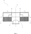
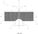
- a screen intake assembly 200 can substantially resemble an overall shape of screen intake assembly 100 but wherein the central manifold 102 has been replaced with a central portion 202 including screen elements to increase the available filtering area, filtering capacity, flow uniformity and efficiency.
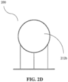
- Screen intake assembly 200 comprises an intake member or other body shown in the form of a central, flanged tee-section 214, a pair of closure members shown as end plates 212a, 212b, the central portion 202, a lower portion 204, screen portions 206a, 206b, and one or more manifold walls 208a, 208b.
- manifold wall 208a, 208b is positioned at the approximate center of screen intake assembly 200, which is shown along axis A.
- Each screen portion 206a, 206b has a screen length 210a, 210b defined between the corresponding manifold wall 208a, 208b, or manifold side when only a single manifold wall is utilized, and the corresponding end plate member 212a, 212b.
- Screen portion 206a, 206b extends continually and substantially from axis A to end closure 212a, 212b.
- Each screen portion 206a, 206b can comprise approximately one-half the entire length of the screen intake assembly 200.
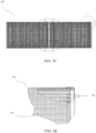
- each screen portion 206a, 206b can include an underlying support structure 220.
- the underlying support structure 220 of screen intake assembly 200 can comprise a plurality of spaced apart horizontal support bars 222 that are each arranged transversely to axis A.
- Each screen portion 206a, 206b and the corresponding underlying support structure 220 including support bars 222 can be fabricated based on the same principles as the embodiments disclosed in U.S. Patent Nos. 6,663, 774, 7,425,264 and 9,399,858 .
- a screen intake assembly 300 can comprise a variation of screen intake assembly 200 with a modification to the one or more manifold walls 208a, 208b.
- manifold walls 208a, 208b can be positioned in proximity to axis A
- manifold walls 308a, 308b can be spaced apart from axis A such that a central portion 302 defines its own screen portion 306c.
- screen portions 306a, 306b each have a screen length 310a, 310b defined between the corresponding manifold wall 308a, 308b and a corresponding end plate member 312a, 312b.
- Screen portion 306c has a screen length 310c that is defined between the manifold walls 308a, 308b. Cooperatively, the screen portions 306a, 306b, 306c define a substantially continuous filtering surface between the end plate members 312a, 312b. As depicted, each screen portion 306a, 306b, 306c can comprise approximately one-third the entire length of the screen intake assembly 300. In other embodiments, the screen portions 306a, 306b can have the same screen length 310a, 310b that differs from screen length 310c of the screen portion 306c.
- FIGS. 4A and 4B A further variation to screen intake assemblies 200 and 300 is illustrated in FIGS. 4A and 4B as screen intake assembly 400.
- Each of screen portions 406a, 406b can be fabricated to include an external flange wall 408 while screen portion 406c can include a pair of opposed external flange walls 408.
- Screen portion 406c can further include one or more external support rib 414 arranged transversely to axis A and extending between the opposed external flange walls 408.
- screen portions 406a, 406b can also include a pair of opposed external flange walls 408 such that end caps 412a, 412b are coupled to the respective external flange wall 408.
- screen portions 406a, 406b can also include one or more external support ribs 414.
- External flange walls 408 can also provide impact protection for the screen portions 406a, 406b, 406c by helping to prevent large objects such as sticks and logs from coming into direct contact with the screen portions 406a, 406b, 406c. It is understood that the use of external flange walls 408 can be secured by bolts or any other material or method that provides a secure closure of flanges and screen portions 406a, 406b, 406c without substantially impacting the integrity of the screen assembly 400.
- each screen intake assembly can comprise a lower portion 204, 304, 404 as seen in FIGS. 2A , 3, and 4A .
- these lower portions 204, 304, 404 can comprise a solid material such as stainless steel or copper-nickel tubing/piping so as to prevent fluid from penetrating the lower portion and entering the screen intake assemblies 200, 300, 400 without being filtered by the corresponding screen portions.
- lower portions 204, 304, 404 can be incorporate their own screen portions similar to that previously described.
- the lower portions 204, 304, 404 can be fabricated from a material having perforations such as slots or apertures that allow fluid intake.
- materials selected for lower portions 204, 304, 404 should provide the necessary support for the screen intake assemblies 200, 300, 400 such that the structural support is not compromised.
- an internal flow modifier 500 can be contained within a screen intake assembly, for example, any of screen intake assemblies 100, 200, 300 and 400.
- internal flow modifier 500 can comprise a perforated flow modifier pipe 502, an internal flow modifier pipe 504, one or more radial support members 508 and a lower portion 510 that is fluidly coupled to the internal flow modifier pipe 504.
- Perforated flow modifier piper 502 can comprise a solid pipe or tube-style materials having a plurality of spaced apart slots 514 to allow fluid to enter the internal flow modifier pipe 504.
- Lower portion 510 can have a cross section substantially equal to or larger than perforated flow modifier pipe 502.
- Lower portion 510 can further comprise a divider plate 512 providing structural support as well as further dividing incoming flow coming from the various screen portions.
- FIGS. 6A - 6D and FIGS. 7A -7D illustrate other alternative embodiments of internal flow modifiers 600 and 700 respectively.
- Each of the internal flow modifiers 600, 700 comprise a perforated flow modifier pipe 602, 702, an internal flow modifier pipe 606, 706, one or more radial supports 608, 708, lower portion 610, 710, and an intake portion (not shown).
- perforated flow modifier pipe 602, 702 comprises a solid material with spaced apart slots 614, 714 to allow fluid intake.
- lower portions 610, 710 can have a cross section substantially equal to the perforated flow modifier pipe 602, 702.
- the cross section of the perforated flow modifier pipe 602, 702 and lower portion 610, 710 can be sized to accommodate a variety of fluid intake assemblies.
- FIGS. 8A - 8D illustrate another alternative embodiment of an internal flow modifier 800.
- Internal flow modifier 800 can comprise a perforated flow modifier piper 802, inlet an internal flow modifier piper 806, one or more radial supports 808, lower portion 810, and an intake portion (not shown).
- perforated flow modifier pipe 802 can comprise a solid material with spaced apart apertures 814 to allow even flow intake along the length of the perforated flow modifier pipe 802, thereby reducing pressure drops and assisting to avoid turbulent flow.
- the cross section of perforated flow modifier pipe 802 and lower portion 810 can be sized to accommodate a variety of fluid intake assemblies.
- an embodiment of an internal flow modifier 900 can comprise circumferential support members 920 and circumferential end portions 922a, 922b.
- circumferential supports 920 are coupled to a perforated internal flow modifier 902 and end portions 922 can be coupled to screen portions (not shown). Both circumferential supports 920 and end portions 922 provide support to the exterior screen portions.
- Each of the circumferential supports 920 can include a variety of flow apertures 920a, 920b to assist in moderating fluid flow within a screen intake assembly.
- the flow apertures 920a between adjacent circumferential supports 920 can be positioned along the same radial axis while in other embodiments, flow aperture 920a can be positioned along the same radial axis as flow aperture 920b or on the adjacent circumferential support 920. Yet in other representative embodiments, adjacent circumferential supports 920 can be arranged so that none of the flow apertures 920a, 920b are aligned in the same radial axis.
- a fluid intake assembly 1000 can be designed for expansion such that screen portions 1002 and an internal flow modifier 1004 can be selectively added to accommodate desired liquid intake rates.
- fluid intake assembly can comprise a center manifold 1006 about which a manifold screen portion 1008 can be attached. On either side of the manifold screen portion 1008, a plurality of individual screen portions 1002a, 1002b, 1002c, 1002d can be operably coupled together.
- Manifold screen portion 1008 can having a manifold screen portion length 1008a while the individual screen portions 1002a, 1002b, 1002c, 1002d each have a corresponding screen portion length 1010a, 1010b, 1010c, 1010d such that an intake assembly screen length 1000a is cooperatively defined by the manifold screen portion length 1008a and the screen portion lengths 1010a, 1010b, 1010c, 1010d.
- the manifold screen portion 1008 and individual screen portions 1002a, 1002b, 1002c, 1002d can be operably connected using manifold walls 1012 or section walls 1014.
- the manifold walls 1012 and section walls 1014 can be located internally of the fluid intake assembly 100 though it will be understood that the manifold walls 1012 and section walls 1014 could be located externally, for example, as external flange walls similar to external flange wall 408 of the embodiment shown in FIGS. 4A and 4B so as to simply onsite assembly and expansion.
- the internal flow modifier 1004 can similarly comprise a plurality of flow modifier sections 1004a, 1004b, 1004c, 1004b that are operably coupled to a central flow modifier 1016 located within the center manifold 1006.
- the length and arrangements of the individual flow modifier sections 1004a, 1004b, 1004c, 1004d can be individually tailored based on desired performance as well as the intake screen assembly length 1000a.
- the internal flow modifier sections 1004a, 1004b, 1004c, 1004d and central flow modifier 1016 can define a perforated flow modifier pipe 1018 and an internal flow modifier pipe 1020.
- the internal flow modifier 1004 can further comprise one or more converging flow modifiers 1020a and 1020b coupled manifold walls 1020, and inlet pipe portion 1004.
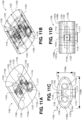
- a screen intake assembly 1100 as shown in FIGS. 11A-11D can comprise a reduced height design 1102 having a non-circular cross-section 1104, herein illustrated as a substantially oval-like cross-section 1106 for a pair of screen portions 1107a, 1107b and a central tee-portion 1107c.
- Non-circular cross-section 1104 is herein defined by each of the screen portions 1107a, 1107b and central tee-portion 1107c having a screen portion height 1109a that is less than a screen portion width 1109b.
- the non-circular cross-section is essentially reversed from that shown in FIGS 11A-11D such that the screen portion height 1109a is greater than the screen portion width 1109b.
- screen portions 1107a, 1107b can each include corresponding exterior screen members 1108a, 1108b and can include a corresponding closure member or end plate 1110a, 1110b that define oval-like perimeters 1112a, 1112b that substantially resemble the oval-like cross-section 1106.
- the central tee-portion 1107c can include a central exterior screen member 1114 as well as a manifold 1116 for delivering a filtered fluid to a point of use.
- the exterior screen members 1108a, 1108b and central exterior screen member 1114 can comprise wedge wire or Vee-Wire ® style screens which are selected to provide desired filtering characteristics as well as desired flow characteristics including, for example, flow capacity and flow velocity.
- the manifold 1116 can further comprise an outlet conduit 1117 that can be fluidly connected to an internal flow modifier 1118.
- the internal flow modifier 1118 can comprise a central collector 1120 and a plurality of lateral collectors 1122 configured to provide desirable flow characteristics within the screen intake assembly 1100 and taking into consideration the non-circular nature of the oval-like cross-section 1106.
- One or more of the central collectors 1120 and the lateral collectors 1122 can comprise perforations or slots 1124 to vary flow characteristics into the manifold 1114.
- wedge wire style screens can be positioned along the screen members 1108a, 1108b, end plates 1110a, 1110b and/or the central tee-section 1116 to get a desired flow capacity and other flow characteristics.
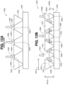
- FIG. 12A a conventional screen filter 1200 of the prior art is shown in FIG. 12A .
- a continuous spool of v-shaped wire 1202 is continually wrapped about and welded to one or more support members 1204.
- a wire gap 1205 is defined between adjacent corners 1208 of the adjacently wrapped and welded v-shaped wire 1202.
- a gap length 1206 of the wire gap 1205 generally equates to the size of particulates filtered or "removed" from fluid that passes through the filer screen 1200, i.e., the filter rating.
- Screen filter 1250 similarly utilizes one or more support members 1204 but uses two different sized v-shaped wires, a first v-shaped wire 1251 and a second v-shaped wire 1252.
- First v-shaped wire 1251 can be defined by a first wire height 1251a and a first wire width 1251b while the second v-shaped wire 1252 is defined by a second wire height 1252a and a second wire width 1252b.
- first wire height 1251a and first wire width 1251b can be larger than the second wire height 1252a and second wire width 1252b such that a first cross-sectional area 1251c (of the first v-shaped wired 1251) is greater than that of a second cross-sectional area 1252c (of the second v-shaped wire 1252).
- first cross-sectional area 1251c is larger than that of the second cross-sectional area 1252c such that a first wire gap 1254 is defined between adjacent wraps of the first v-shaped wire 1251 while a second wire gap 1256 is defined between the second v-shaped wire 1252 and the first v-shaped wire 1251 on either side of the second v-shaped wire 1252.
- first wire gap 1254 can have a first gap length 1258 that is substantially larger than a second gap length 1260 of the second wire gap 1256.
- the second wire gap 1256 can generally equate to the filter rating of the improved screen filter 1250 while the first wire gap 1254 defines an initial rough filter that can reduce an effective top surface velocity in an attempt to reduce impingement of wildlife and/or debris at the second wire gap 1256.
- first wire gap 1254 can be sized such that a fluid velocity through the first wire gap 1254 is equal or less than about 0.5 ft/sec such that aquatic life such as, for example, fish can avoid being trapped against an exterior of the improved screen filter 1250.
- the number of second wire gaps 1256 defined in the available surface area of the improved screen filter 1250 will be larger than the number of wire gaps 1206 in the same surface area of the conventional screen filter 1200.
- screen filter 1250 provides more available filtering area than the conventional screen filter 1200 so as to increase the overall capacity of any screen intake assembly utilizing the improved screen filter 1250 while still maintaining a reduced fluid velocity at the exterior surface of the improved screen filter 1250.
- one or more of the first wire height 1251a, first wire width 1251b, second wire height 1252a and second wire height 1252b can be adjusted to selectively change one or both of the first wire gap 1254 and second wire gap 1256 to achieve desired fluid velocities through one or both of the first wire gap 1254 and second wire gap 1256.
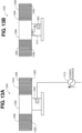
- a removal system 1300 can comprise an oscillator assembly 1302 to continually or selectively induce vibration to the screen assembly to deter and/or remove contaminants from the screen assembly as shown in Figure 13A .
- Oscillator assembly 1302 can comprise a device capable of generating ultrasonic or low frequency vibrations.
- a screen intake assembly 1304 can comprise a central portion 1306 operably coupled to one or more screen portions 1308.
- the oscillator assembly 1302 can be operably attached to the central portion 1306 such that vibrations created by the oscillator assembly 1302 are transmitted through the central portion 1306 and to a screen filter 1309 on the exterior of each screen portion 1308.
- the oscillator assembly 1302 can be operably connected to a remote power source 1310 for example, an electrical grid or an onshore/barge/rig mounted generator.
- the oscillator assembly 1302 can be powered using a turbine or propeller style assembly 1312 to convert a filtered fluid flow through the central portion 1306 to rotational energy that can directly power the oscillator assembly 1302 or to generate energy for storage in a battery source that is integral to or located in proximity to the oscillator assembly 1302 as shown in FIG. 13B .
- a screen intake assembly 1350 can comprise a flow-through oscillation system 1352 to continually induce vibration absent any moving or powered assemblies as shown in Figures 13C and 13D .
- the screen intake assembly 1350 can comprise a pair of screen portions 1354a, 1354b that are operably connected to a central-tee portion 1356.
- the screen intake assembly 1350 can further comprise an internal flow modifier system 1358 to provide desirable flow characteristics through the screen portions 1354a, 1354b.
- the internal flow modifier system 1358 can further comprise one or more flow-through oscillators 1360 that are positioned between the internal flow modifier system 1358 and the screen portions 1354a, 1354b. As best seen in FIG.
- each flow-through modifier 1360 can comprise a substantially tubular body 1362 defining an inlet 1364, a fluid channel 1366 and an outlet 1368.
- Outlet 1368 can define a connecting member 1370 that attaches to an aperture 1372 in the internal flow modifier system 1358 such that the fluid channel 1366 is fluidly connected to an interior flow-though portion 1374 of the internal flow modifier system 1358.
- suction is created at the outlet 1368 such that fluid is drawn into the inlet 1364 and through the fluid channel 1366.
- Inlet 1368 and/or the fluid channel 1366 can be configured such that the fluid flow through the flow-through oscillator 1360 generates a resistance pattern or "whistle” that causes vibration which is ultimately transmitted to the screen portions 1364a, 1364b through the physically connection of the internal flow modifier system 1358 to the central tee-portion 1356.
- This resistance pattern or "whistle” is essentially continuous as long as fluid is flowing into the interior flow-through portion 1374.
- no external or stored energy source is required for operation and there are no moving parts or mechanical assemblies requiring maintenance.
- the flow-through oscillation system 1352 operates to limit attachment and/or accumulation of debris or biofouling materials in a continuous and economical manner.
- the various screen intake assemblies of both the prior art as well as the novel configurations disclosed herein can further incorporate internal cleaning systems to remove accumulated debris and biofouling.
- FIG. 14A it is well known in the prior art to utilize an internal air burst system 1400 within a screen intake assembly 1402 to delivery pulses of pressurize air 1403 to an interior portion 1404 of the screen intake assembly 1402.
- the internal air burst system 1400 comprises an airburst pipe 1406 positioned in proximity to a lower portion 1408 of a screen portion 1410.
- the airburst pipe 1406 is in fluid communication with a remotely located air compressor such as, for example, a compressor located onshore, on a barge or on a rig.
- the airburst pipe 1406 can be attached an airburst manifold located within a central portion of the screen intake assembly. Where the screen intake assembly comprises multiple screen portions 1410, an airburst pipe 1406 can be located within each screen portion 1410 and each airburst pipe 1406 can be operably connected to the airburst manifold. Generally, pulses of pressurized air can be supplied through the airburst pipe 1406 whereby the pulse of pressurize air starts displacing water proximate the lower portion 1408 and subsequently expands to fill and displace water throughout the screen portion 1410 to displace contaminants from the surface of the screen portion 1410.
- a plurality of airburst pipes can be positioned at a variety of locations in addition to the lower portion 1408 as shown in FIGS. 14B-14D .
- airburst pipe 1422a can be located proximate the lower portion 1408
- airburst pipes 1422b, 1422c can be located proximate opposed sides 1424a, 1424b of the screen portion 1410
- airburst pipe 1422d can be located proximate an upper portion 1426 of the screen portion 1410.
- the improved airburst system 1420 is illustrated as having four airburst pipes 1422a, 1422b, 1422c, 1422d, it will be understood that variables including, for example, the size of a screen intake assembly and the quality of the fluid being filtered can lead to designs utilizing either fewer airburst pipes with at least two being required or more than four airburst pipes.
- the airburst pipes 1422a, 1422b, 1422c, 1422d can all be operably connected to an airburst manifold located within a central portion 1428 of the screen intake assembly 1402.
- each of the screen portions 1430a, 1430b can include the same arrangement of airburst pipes 1422a, 14222b, 1422c, 14222d.
- pulses of pressurized air 1403 can be simultaneously delivered through each airburst pipe 1422a, 1422b, 1422c, 1422d as shown in FIG. 14B .
- the pulses of pressurized air are delivered through nozzles 1425a, slots, 1425 or similar apertures positioned along the length of each airburst pipe 1422a, 1422b, 1422c, 1422d.
- the pulses of pressurize air can be radially, sequentially delivered through the airburst pipes 1422a, 1422b, 1422c, 1422d as shown in FIG. 14C .
- the pulses of pressurized air can be sequentially delivered along an intake length 1432 defined between a first end 1434 and a second end 1436 of a screen intake assembly 1438 as seen in Figure 14D .
- the screen intake assembly 1438 of FIG. 14D contains first and second screen portions 1443a, 1443b connected to a central tee portion 1442, the same principle can be applied to provide pulses of pressurize air along an intake length that makes use of only a single screen portion.
- the particular arrangement and sequence of the pressurized air pulse delivery will generally be tailored to the installation and can depend upon the installation conditions and the type and quantity of particulate and biofouling accumulation.
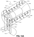
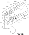
- FIGS. 15A and 15B Yet another variation of a screen intake assembly 1500 of the present invention is shown in FIGS. 15A and 15B .
- screen intake assembly 1500 includes a central tee-portion 1502 and a screen portion 1504. While only a single screen portion 1504 is shown, it will be understood that additional screen portions can be operably connected to the central tee-portion 1502 based upon fluid flow requirements.
- the screen intake assembly 1500 includes an internal flow modifier assembly 1506 and an integrated self-cleaning system 1508.
- the internal flow modifier assembly 1506 is configured to promote desirable flow conditions through a screen filter 1510 on one or both of the central tee-portion 1502 and the screen portion 1504. As seen in FIG.
- the integrated self-cleaning system 1508 can comprise an intake scoop 1511 that is operably connected to a flow modifier conduit 1512 that is positioned within the central tee-portion 1502.
- One or more cleaning inlet pipes 1514 can be fluidly connected to the intake scoop 1511 such that a portion of fluid flowing between the intake scoop 1511 and the central tee-portion 1502 is directed into the cleaning inlet pipes 1514.
- the cleaning inlet pipes 1514 are fluidly connected to one or more cleaning pipes 1516 that are positioned axially and radially along a length defined by one or or both of the central tee-portion 1502 and screen portion 1504.
- the one or more cleaning pipes 1516 can be positioned within the screen intake assembly 1500 and in proximity to an interior surface of the screen filter 1510. Alternatively, the one or more cleaning pipes 1516 can be positioned outside the screen intake assembly 1500 and in proximity to an exterior surface of the screen filter 1510.
- Each cleaning pipe 1516 generally includes a plurality of spaced apart apertures 1518, slots or perforations.
- a nozzle 1520 can be operably mounted within each aperture 1518 as shown in FIG. 15A . The fluid flow is directed through the cleaning inlet pipes 1514, into the cleaning pipes 1516 and out the apertures 1518/nozzles 1520.
- the fluid flow out of the apertures 1518/nozzles 1520 can be directed against the screen filter 1510 or along the screen filter 1510 to dislodge and/or inhibit the attachment of any contaminants.
- the integrated self-cleaning system 1508 is a passive system requiring no external power source and no moving parts that could require ongoing maintenance.
- the intake scoop 1511 can be located within the internal flow modifier assembly 1506 at a location internal to the screen portion 1504 as opposed to the central tee-portion 1502.
Landscapes
- Chemical & Material Sciences (AREA)
- Chemical Kinetics & Catalysis (AREA)
- Engineering & Computer Science (AREA)
- General Engineering & Computer Science (AREA)
- Mechanical Engineering (AREA)
- Civil Engineering (AREA)
- Structural Engineering (AREA)
- Filtration Of Liquid (AREA)
- Filtering Materials (AREA)
- Filtering Of Dispersed Particles In Gases (AREA)
Description
- The present invention is directed to screen intakes for filtering incoming water from a water source. More specifically, the present invention is directed to screen intakes and related methods that provide for increased intake capacities and improved performance.
- Water collection systems are typically used to provide water to end users such as manufacturing plants, cities, irrigation systems, and power generation facilities located adjacent a body of water such as a river, lake, or salt water bodies. The end users may employ this type of system as an alternative to drilling water wells or buying water directly from a municipal source. Additionally, use of these systems may be determined by the location of the end user, for example remote locations where water from a municipal source and/or electrical power to operate pumps is not readily available. These water collection systems are advantageous in that they can be operated efficiently and economically with an ability to adapt to varying water and environmental conditions.
- Conventional water collection systems typically use an inlet pipe that is adapted to transport water from a position submerged in a body of water to an end user located adjacent to or proximate the body of water. An inlet pipe is generally submerged in the body of water and the end of the inlet pipe is typically coupled to an intake screen assembly that defines one or more filtering members. One common intake screen configuration is a Tee-style configuration having two filtering screens on opposing ends. A typical construction for large intake screen assemblies is a flanged tee section with two screen cylinders that are cantilevered from opposite ends of the tee section, and with solid closures such as flat plates, cones, or dished heads on the distal ends of each screen cylinder. These closures can be removable, or include access portals within their design. The separate components of the assemblies are usually welded together.
- Regardless of the specific configuration, the screen intakes are generally configured to prevent waterborne debris of a certain size, from entering the inlet pipe. At the same time, the screen intakes must be designed to protect aquatic life while filtering debris along the length of the intake screen surfaces. To do this, the flow velocity through the screens should be kept below a maximum peal level, which may be about 0.5 f/s or other limits that are defined by local requirements and/or specifications. One way to reduce the flow resistance and control screen intakes must be designed to protect aquatic life while filtering debris along the length of the intake screen surfaces. To do this, the flow velocity through the screens should be kept below a maximum peal level, which may be about 0.5 f/s or other limits that are defined by local requirements and/or specifications. One way to reduce the flow resistance and control the flow velocity at the screen's surface is to use flow modifiers inside the screen intake. For example, the Johnson Screens® brand of screen intakes improves flow uniformity across the filtering screens using flow modifiers as disclosed in
U.S. Pat. No. 6,051,131 andU.S. Patent Publication 2012/0298572 . - In addition to designs that are optimized for flow performance, screen intake design must also take into account external forces such as, for example, environmental conditions such as ice formation as well as potential impact loads when the screen intakes are located at their submerged collection locations. As such, it would be advantages to improve upon conventional screen intake designs so as to not only increase flow performance within and across a screen intake but to also increase the structural strength of the screen intake so as to better resist external pressures and impact loads.
-
US 2754003 describes a strainer for use with a washing machine in the form of an elongate perforated shell. -
US 5820751 describes a float portion, a drain head portion, and an outlet pipe portion which are sequentially connected. -
US 2012/055869 describes a screen configuration provided for the extraction of wastewater from a wastewater reactor, while precluding the entry of biological support media. -
US 2674376 describes a T-shaped filter or screen with a vertical stem section set over a container outlet, and a horizontal section on top of the vertical section, each portion being of cross-section obviating flat particle-collecting areas. -
US 2013/206706 describes a screen intake apparatus for a water intake system uses a cleaning system to clean one or more screen intakes. - The invention to which this European patent relates is defined in the appended claims. Embodiments disclosed herein include a screen intake assembly having a central manifold for the attachment of individual screen portions and internal flow modifiers. In some embodiments, the central manifold can include a central screen portions such that an entire intake assembly length includes an external screen for increasing a fluid intake capacity of the screen intake assembly. The screen intake assembly can comprise individual screen sections that are selectively attached to the central manifold such that the fluid intake capacity of the screen intake assembly can be selectively adjusted. In some embodiments, the screen sections and central manifold can be adjacently assembled utilizing an external connection, such as, for example, an external flange wall to facilitate assembly at point of use. In some embodiments, the internal flow modifiers can be operably coupled to the central manifold to selectively influence fluid flow characteristics within the screen intake assembly. The internal flow modifiers can be comprised of individual flow modifier sections that allow the internal flow modifier to be expanded to accommodate the number of screen portions attached to the central manifold.
- In general, the embodiments of the present invention can comprise an adjustable or expandable screen intake assembly that can utilize a central manifold screen section, individual screen sections, a central flow modifier and individual flow modifier sections to adjust fluid intake characteristics including, for example, flow capacity, pressure drop, screen utilization, and the avoidance of turbulent flow conditions within the screen intake assembly. In addition, screen intake assemblies of the preset invention can include integral cleaning assemblies that serve to remove particulates and biofouling.
- The above summary is not intended to describe each illustrated embodiment or every implementation of the subject matter hereof. The figures and the detailed description that follow more particularly exemplify various embodiments.
- Subject matter hereof may be more completely understood in consideration of the following detailed description of various embodiments in connection with the accompanying figures.
Figures 2A-2E andFigure 3 are provided for illustrative purposes to provide background for disclosed embodiments falling within the scope of the appended claims. -
FIG. 1 is a partially hidden section view of a screen intake assembly of the prior art. -
FIG. 2A is a perspective view of a screen intake assembly. -
FIG. 2B is a front view of the screen intake assembly ofFIG. 2A . -
FIG. 2C is a top view of the screen intake assembly ofFIG. 2A . -
FIG. 2D is an end view of the screen intake assembly ofFIG. 2A . -
FIG. 2E is a partially hidden, section view of the screen intake assembly ofFIG. 2A taken at Detail A ofFIG. 2C depicting an internal support structure. -
FIG. 3 is a perspective view of a screen intake assembly. -
FIG. 4A is a perspective view of screen intake assembly according to an embodiment of the present invention. -
FIG. 4B is an end view of the screen intake assembly ofFIG. 4A . -
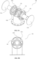
FIG. 5A is a perspective view of an internal flow modifier for use with a screen intake assembly according to an embodiment of the present invention. -
FIG. 5B is a top view of the internal flow modifier ofFIG. 5A . -
FIG. 5C is a front view of the internal flow modifier ofFIG. 5A . -
FIG. 5D is a bottom view of the internal flow modifier ofFIG. 5A . -
FIG. 5E is an end view of the internal flow modifier ofFIG. 5A . -
FIG. 5F is a bottom, perspective view of the internal flow modifier ofFIG. 5A . -
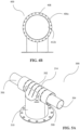
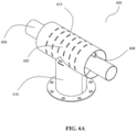
FIG 6A is a perspective view of an internal flow modifier for use with a screen intake assembly according to an embodiment of the present invention. -
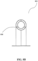
FIG. 6B is an end view of the internal flow modifier ofFIG. 6A . -
FIG. 6C is a top view of the internal flow modifier ofFIG. 6A . -
FIG. 6D is a front view of the internal flow modifier ofFIG. 6A -
FIG 7A is a perspective view of an internal flow modifier for use with a screen intake assembly according to an embodiment of the present invention. -
FIG. 7B is an end view of the internal flow modifier ofFIG. 7A . -
FIG. 7C is a top view of the internal flow modifier ofFIG. 7A . -
FIG. 7D is a front view of the internal flow modifier ofFIG. 7A . -
FIG 8A is a perspective view of an internal flow modifier for use with a screen intake assembly according to an embodiment of the present invention. -
FIG. 8B is an end view of the internal flow modifier ofFIG. 8A . -
FIG. 8C is a top view of the internal flow modifier ofFIG. 8A . -
FIG. 8D is a front view of the internal flow modifier ofFIG. 8A . -
FIG 9A is a perspective view of an internal flow modifier for use with a screen intake assembly according to an embodiment of the present invention. -
FIG. 9B is an end view of the internal flow modifier ofFIG. 9A . -
FIG. 9C is a front view of the internal flow modifier ofFIG. 9A . -
FIG. 9 is a bottom view of the internal flow modifier ofFIG. 9A . -
FIG. 10A is a perspective view of an expandable screen intake assembly according to an embodiment of the present invention. -
FIG. 10B is a partially hidden, section side view of the expandable screen assembly ofFIG. 10A taken at line B-B ofFIG. 10A . -
FIG. 11A is a partially hidden, perspective view of a screen intake assembly according to a representative embodiment of the present invention. -
FIG. 11B is a partially hidden, perspective view of the screen intake assembly ofFIG. 11A . -
FIG. 11C is a partially hidden, end view of the screen intake assembly ofFIG. 11A . -
FIG. 11D is a partially hidden, side view of the screen intake assembly ofFIG. 11A . -
FIG. 12A is a section view of a screen filter according to an embodiment of the prior art. -
FIG. 12B is a section view of a screen filter according to an embodiment of the present invention. -
FIG. 13A is a side view of a screen intake assembly according to an embodiment of the present invention. -
FIG. 13B is a side view of a screen intake assembly according to an embodiment of the present invention. -
FIG. 13C is a partially hidden, perspective view of a screen intake assembly according to an embodiment of the present invention. -
FIG. 13D is a detailed, perspective view of a flow-through oscillator assembly as utilized in the screen intake assembly ofFIG. 13C . -
FIG. 14A is an end view of an air burst system for use with a screen intake assembly according to the prior art. -
FIG. 14B is an end view of an air burst system for use with a screen intake assembly according an embodiment of the present invention. - FIG. 14C1 is an end view of an air burst system for use with a screen intake assembly according an embodiment of the present invention.
-
FIG. 14D is a side view of an air burst system for use with a screen intake assembly according an embodiment of the present invention. -
FIG. 15A is a partially hidden, perspective view of an integrated cleaning system for use with a screen intake assembly according to embodiment of the present invention. -
FIG. 15B is a partially hidden, perspective view of an integrated cleaning system for use with a screen intake assembly according to embodiment of the present invention. -
FIG. 1 illustrates a conventionalintake screen assembly 100 of the prior art. Anintake screen assembly 100 can generally comprise an intake member or other body shown in the form of a central, flanged tee-section 10, one or more closure members shown as end plates 20a, 20b, acenter manifold 102, alower portion 104, one or more screen portions 106a, 106b, and one or moremanifold walls screen intake assembly 100 is shown along axisA. Center manifold 102 extends substantially and continually from axis A tomanifold wall respective manifold wall screen intake assembly 100.Screen intake assembly 100 can also comprise flow modifiers, various embodiments of which are disclosed herein. - As seen in
FIGS. 2A- 2E , ascreen intake assembly 200 can substantially resemble an overall shape ofscreen intake assembly 100 but wherein thecentral manifold 102 has been replaced with a central portion 202 including screen elements to increase the available filtering area, filtering capacity, flow uniformity and efficiency.Screen intake assembly 200 comprises an intake member or other body shown in the form of a central, flanged tee-section 214, a pair of closure members shown asend plates lower portion 204,screen portions manifold walls 208a, 208b. In embodiments,manifold wall 208a, 208b is positioned at the approximate center ofscreen intake assembly 200, which is shown along axis A. Eachscreen portion corresponding manifold wall 208a, 208b, or manifold side when only a single manifold wall is utilized, and the correspondingend plate member Screen portion closure screen portion screen intake assembly 200. - With reference to
FIGS. 2C and 2E , eachscreen portion screen intake assembly 200 can comprise a plurality of spaced apart horizontal support bars 222 that are each arranged transversely to axis A. Eachscreen portion U.S. Patent Nos. 6,663, 774, 7,425,264 and9,399,858 - As seen in
Figure 3 , ascreen intake assembly 300 can comprise a variation ofscreen intake assembly 200 with a modification to the one or moremanifold walls 208a, 208b. Instead ofmanifold walls 208a, 208b being positioned in proximity to axis A,manifold walls 308a, 308b can be spaced apart from axis A such that acentral portion 302 defines its own screen portion 306c. As such,screen portions screen length corresponding manifold wall 308a, 308b and a correspondingend plate member manifold walls 308a, 308b. Cooperatively, thescreen portions end plate members screen portion screen intake assembly 300. In other embodiments, thescreen portions same screen length - A further variation to screen
intake assemblies FIGS. 4A and4B asscreen intake assembly 400. Each ofscreen portions 406a, 406b can be fabricated to include anexternal flange wall 408 whilescreen portion 406c can include a pair of opposedexternal flange walls 408.Screen portion 406c can further include one or more external support rib 414 arranged transversely to axis A and extending between the opposedexternal flange walls 408. Though not depicted, it will be understood thatscreen portions 406a, 406b can also include a pair of opposedexternal flange walls 408 such thatend caps external flange wall 408. In addition,screen portions 406a, 406b can also include one or more external support ribs 414. Through the use of theexternal flange walls 408, on-site assembly or expansion of thescreen intake assembly 400 can be quickly and easily accomplished.External flange walls 408 can also provide impact protection for thescreen portions screen portions external flange walls 408 can be secured by bolts or any other material or method that provides a secure closure of flanges andscreen portions screen assembly 400. - Referring now to screen
intake assemblies lower portion FIGS. 2A ,3, and 4A . As illustrated, theselower portions screen intake assemblies lower portions lower portions lower portions screen intake assemblies - In addition to the external features described with respect to
screen intake assemblies FIGS. 5A -5F , aninternal flow modifier 500 can be contained within a screen intake assembly, for example, any ofscreen intake assemblies internal flow modifier 500 can comprise a perforatedflow modifier pipe 502, an internalflow modifier pipe 504, one or moreradial support members 508 and a lower portion 510 that is fluidly coupled to the internalflow modifier pipe 504. Perforatedflow modifier piper 502 can comprise a solid pipe or tube-style materials having a plurality of spaced apart slots 514 to allow fluid to enter the internalflow modifier pipe 504. The size, shape and spacing of slots 514 to allow for even flow intake along the length of the perforatedflow modifier pipe 502, thereby reducing pressure drops and assist in avoiding turbulent flow. Lower portion 510 can have a cross section substantially equal to or larger than perforatedflow modifier pipe 502. Lower portion 510 can further comprise adivider plate 512 providing structural support as well as further dividing incoming flow coming from the various screen portions. -
FIGS. 6A - 6D andFIGS. 7A -7D illustrate other alternative embodiments ofinternal flow modifiers internal flow modifiers flow modifier pipe flow modifier pipe radial supports lower portion flow modifier pipe slots 614, 714 to allow fluid intake. In representative embodiments,lower portions flow modifier pipe flow modifier pipe lower portion -
FIGS. 8A - 8D illustrate another alternative embodiment of aninternal flow modifier 800.Internal flow modifier 800 can comprise a perforatedflow modifier piper 802, inlet an internalflow modifier piper 806, one or moreradial supports 808,lower portion 810, and an intake portion (not shown). According to embodiments, perforatedflow modifier pipe 802 can comprise a solid material with spaced apartapertures 814 to allow even flow intake along the length of the perforatedflow modifier pipe 802, thereby reducing pressure drops and assisting to avoid turbulent flow. In embodiments, the cross section of perforatedflow modifier pipe 802 andlower portion 810 can be sized to accommodate a variety of fluid intake assemblies. - As illustrated in
FIGS. 9A - 9D , an embodiment of aninternal flow modifier 900 can comprisecircumferential support members 920 andcircumferential end portions 922a, 922b. According to embodiments,circumferential supports 920 are coupled to a perforated internal flow modifier 902 and end portions 922 can be coupled to screen portions (not shown). Bothcircumferential supports 920 and end portions 922 provide support to the exterior screen portions. Each of the circumferential supports 920 can include a variety offlow apertures flow apertures 920a between adjacentcircumferential supports 920 can be positioned along the same radial axis while in other embodiments,flow aperture 920a can be positioned along the same radial axis asflow aperture 920b or on the adjacentcircumferential support 920. Yet in other representative embodiments, adjacent circumferential supports 920 can be arranged so that none of theflow apertures - According to an alternative embodiment as depicted in
FIG. 10 , afluid intake assembly 1000 can be designed for expansion such thatscreen portions 1002 and aninternal flow modifier 1004 can be selectively added to accommodate desired liquid intake rates. Generally, fluid intake assembly can comprise acenter manifold 1006 about which amanifold screen portion 1008 can be attached. On either side of themanifold screen portion 1008, a plurality ofindividual screen portions Manifold screen portion 1008 can having a manifoldscreen portion length 1008a while theindividual screen portions screen portion length assembly screen length 1000a is cooperatively defined by the manifoldscreen portion length 1008a and thescreen portion lengths manifold screen portion 1008 andindividual screen portions manifold walls 1012 orsection walls 1014. As illustrated, themanifold walls 1012 andsection walls 1014 can be located internally of thefluid intake assembly 100 though it will be understood that themanifold walls 1012 andsection walls 1014 could be located externally, for example, as external flange walls similar toexternal flange wall 408 of the embodiment shown inFIGS. 4A and4B so as to simply onsite assembly and expansion. Theinternal flow modifier 1004 can similarly comprise a plurality offlow modifier sections central flow modifier 1016 located within thecenter manifold 1006. The length and arrangements of the individualflow modifier sections screen assembly length 1000a. In one representative embodiment, the internalflow modifier sections central flow modifier 1016 can define a perforatedflow modifier pipe 1018 and an internalflow modifier pipe 1020. Theinternal flow modifier 1004 can further comprise one or more convergingflow modifiers manifold walls 1020, andinlet pipe portion 1004. With the expandable nature offluid intake assembly 1000, an almost infinite arrangement ofscreen portions 1002 andinternal flow modifier 1004 can be fabricated or assembled on-site. In some instances, existingfluid intake assemblies 1000 can be contracted or expanded on-site as fluid needs change at a point of use. - As illustrated and described with reference to the previous embodiments, various fluid intake assembly designs are contemplated in which the one or more screen members are fabricated so as to define a substantially round or circular cross-sectional area between the closure members/end plates. Alternatively, there may be installations, for example, locations having shallow depths such as rivers, where it would be advantageous to have a non-circular cross-section to reduce an overall height, or even width, of the screen intake assembly. For example, a
screen intake assembly 1100 as shown inFIGS. 11A-11D can comprise a reducedheight design 1102 having anon-circular cross-section 1104, herein illustrated as a substantially oval-like cross-section 1106 for a pair ofscreen portions portion 1107c.Non-circular cross-section 1104 is herein defined by each of thescreen portions portion 1107c having ascreen portion height 1109a that is less than ascreen portion width 1109b. Though not illustrated, it will be understood that there may be installation advantages wherein the non-circular cross-section is essentially reversed from that shown inFIGS 11A-11D such that thescreen portion height 1109a is greater than thescreen portion width 1109b. Still in other embodiments, it may be advantageous to have other geometrical configurations for thenon-circular cross-section 1104 including, example, squares, rectangles, triangles pentagons, hexagons, octagons and the like. As illustrated,screen portions exterior screen members end plate like perimeters like cross-section 1106. The central tee-portion 1107c can include a centralexterior screen member 1114 as well as amanifold 1116 for delivering a filtered fluid to a point of use. Theexterior screen members exterior screen member 1114 can comprise wedge wire or Vee-Wire ® style screens which are selected to provide desired filtering characteristics as well as desired flow characteristics including, for example, flow capacity and flow velocity. The manifold 1116 can further comprise anoutlet conduit 1117 that can be fluidly connected to aninternal flow modifier 1118. In order to accommodate the oval-like cross-section 1106, theinternal flow modifier 1118 can comprise acentral collector 1120 and a plurality oflateral collectors 1122 configured to provide desirable flow characteristics within thescreen intake assembly 1100 and taking into consideration the non-circular nature of the oval-like cross-section 1106. One or more of thecentral collectors 1120 and thelateral collectors 1122 can comprise perforations orslots 1124 to vary flow characteristics into themanifold 1114. Likewise, wedge wire style screens can be positioned along thescreen members end plates section 1116 to get a desired flow capacity and other flow characteristics. - In addition to the variety of configurations for screen intake assemblies described previously, it can be advantageous to vary the construction technique of the individual screen portions themselves. For example, a
conventional screen filter 1200 of the prior art is shown inFIG. 12A Generally, a continuous spool of v-shapedwire 1202 is continually wrapped about and welded to one ormore support members 1204. Generally, awire gap 1205 is defined betweenadjacent corners 1208 of the adjacently wrapped and welded v-shapedwire 1202. Agap length 1206 of thewire gap 1205 generally equates to the size of particulates filtered or "removed" from fluid that passes through thefiler screen 1200, i.e., the filter rating. - Not only can the disclosed screen intake assemblies of the current invention utilize the
conventional screen filter 1200 but they can also use animproved screen filter 1250 as shown inFIG. 12B .Screen filter 1250 similarly utilizes one ormore support members 1204 but uses two different sized v-shaped wires, a first v-shapedwire 1251 and a second v-shapedwire 1252. First v-shapedwire 1251 can be defined by afirst wire height 1251a and afirst wire width 1251b while the second v-shapedwire 1252 is defined by asecond wire height 1252a and asecond wire width 1252b. As illustrated, thefirst wire height 1251a andfirst wire width 1251b can be larger than thesecond wire height 1252a andsecond wire width 1252b such that a firstcross-sectional area 1251c (of the first v-shaped wired 1251) is greater than that of a secondcross-sectional area 1252c (of the second v-shaped wire 1252). As illustrated, firstcross-sectional area 1251c is larger than that of the secondcross-sectional area 1252c such that afirst wire gap 1254 is defined between adjacent wraps of the first v-shapedwire 1251 while asecond wire gap 1256 is defined between the second v-shapedwire 1252 and the first v-shapedwire 1251 on either side of the second v-shapedwire 1252. As illustrated,first wire gap 1254 can have afirst gap length 1258 that is substantially larger than asecond gap length 1260 of thesecond wire gap 1256. Thesecond wire gap 1256 can generally equate to the filter rating of theimproved screen filter 1250 while thefirst wire gap 1254 defines an initial rough filter that can reduce an effective top surface velocity in an attempt to reduce impingement of wildlife and/or debris at thesecond wire gap 1256. For example,first wire gap 1254 can be sized such that a fluid velocity through thefirst wire gap 1254 is equal or less than about 0.5 ft/sec such that aquatic life such as, for example, fish can avoid being trapped against an exterior of theimproved screen filter 1250. In addition, when the second v-shapedwire 1252 is smaller than that of the v-shapedwire 1202 ofconventional screen filter 1200, the number ofsecond wire gaps 1256 defined in the available surface area of theimproved screen filter 1250 will be larger than the number ofwire gaps 1206 in the same surface area of theconventional screen filter 1200. By providing more of thesecond wire gaps 1256,screen filter 1250 provides more available filtering area than theconventional screen filter 1200 so as to increase the overall capacity of any screen intake assembly utilizing theimproved screen filter 1250 while still maintaining a reduced fluid velocity at the exterior surface of theimproved screen filter 1250. Depending upon desired flow characteristics, one or more of thefirst wire height 1251a,first wire width 1251b,second wire height 1252a andsecond wire height 1252b can be adjusted to selectively change one or both of thefirst wire gap 1254 andsecond wire gap 1256 to achieve desired fluid velocities through one or both of thefirst wire gap 1254 andsecond wire gap 1256. - In yet another alternative embodiment, the various screen intake assemblies of both the prior art and the novel configurations disclosed herein can further incorporate a removal system for limiting attachment and/or detaching biofouling materials and other debris from a screen filter. For example, a
removal system 1300 can comprise anoscillator assembly 1302 to continually or selectively induce vibration to the screen assembly to deter and/or remove contaminants from the screen assembly as shown inFigure 13A .Oscillator assembly 1302 can comprise a device capable of generating ultrasonic or low frequency vibrations. Generally, ascreen intake assembly 1304 can comprise acentral portion 1306 operably coupled to one ormore screen portions 1308. Theoscillator assembly 1302 can be operably attached to thecentral portion 1306 such that vibrations created by theoscillator assembly 1302 are transmitted through thecentral portion 1306 and to ascreen filter 1309 on the exterior of eachscreen portion 1308. As shown inFIG. 13A , theoscillator assembly 1302 can be operably connected to aremote power source 1310 for example, an electrical grid or an onshore/barge/rig mounted generator. Alternatively, theoscillator assembly 1302 can be powered using a turbine orpropeller style assembly 1312 to convert a filtered fluid flow through thecentral portion 1306 to rotational energy that can directly power theoscillator assembly 1302 or to generate energy for storage in a battery source that is integral to or located in proximity to theoscillator assembly 1302 as shown inFIG. 13B . - In a variation to the
removal system 1300, ascreen intake assembly 1350 can comprise a flow-throughoscillation system 1352 to continually induce vibration absent any moving or powered assemblies as shown inFigures 13C and 13D . As illustrated, thescreen intake assembly 1350 can comprise a pair ofscreen portions tee portion 1356. Thescreen intake assembly 1350 can further comprise an internalflow modifier system 1358 to provide desirable flow characteristics through thescreen portions flow modifier system 1358 can further comprise one or more flow-throughoscillators 1360 that are positioned between the internalflow modifier system 1358 and thescreen portions FIG. 13D , each flow-throughmodifier 1360 can comprise a substantiallytubular body 1362 defining aninlet 1364, afluid channel 1366 and anoutlet 1368.Outlet 1368 can define a connectingmember 1370 that attaches to anaperture 1372 in the internalflow modifier system 1358 such that thefluid channel 1366 is fluidly connected to an interior flow-thoughportion 1374 of the internalflow modifier system 1358. As fluid flows into the internalflow modifier system 1358 and through the interior flow-thoughportion 1374, suction is created at theoutlet 1368 such that fluid is drawn into theinlet 1364 and through thefluid channel 1366.Inlet 1368 and/or thefluid channel 1366 can be configured such that the fluid flow through the flow-throughoscillator 1360 generates a resistance pattern or "whistle" that causes vibration which is ultimately transmitted to the screen portions 1364a, 1364b through the physically connection of the internalflow modifier system 1358 to the central tee-portion 1356. This resistance pattern or "whistle" is essentially continuous as long as fluid is flowing into the interior flow-throughportion 1374. As such, no external or stored energy source is required for operation and there are no moving parts or mechanical assemblies requiring maintenance. As such, the flow-throughoscillation system 1352 operates to limit attachment and/or accumulation of debris or biofouling materials in a continuous and economical manner. - The various screen intake assemblies of both the prior art as well as the novel configurations disclosed herein can further incorporate internal cleaning systems to remove accumulated debris and biofouling. As shown in
FIG. 14A , it is well known in the prior art to utilize an internalair burst system 1400 within ascreen intake assembly 1402 to delivery pulses ofpressurize air 1403 to an interior portion 1404 of thescreen intake assembly 1402. Generally, the internalair burst system 1400 comprises anairburst pipe 1406 positioned in proximity to alower portion 1408 of ascreen portion 1410. Typically, theairburst pipe 1406 is in fluid communication with a remotely located air compressor such as, for example, a compressor located onshore, on a barge or on a rig. Theairburst pipe 1406 can be attached an airburst manifold located within a central portion of the screen intake assembly. Where the screen intake assembly comprisesmultiple screen portions 1410, anairburst pipe 1406 can be located within eachscreen portion 1410 and eachairburst pipe 1406 can be operably connected to the airburst manifold. Generally, pulses of pressurized air can be supplied through theairburst pipe 1406 whereby the pulse of pressurize air starts displacing water proximate thelower portion 1408 and subsequently expands to fill and displace water throughout thescreen portion 1410 to displace contaminants from the surface of thescreen portion 1410. - In an
improved airburst system 1420 of the present invention, a plurality of airburst pipes can be positioned at a variety of locations in addition to thelower portion 1408 as shown inFIGS. 14B-14D . For example,airburst pipe 1422a can be located proximate thelower portion 1408,airburst pipes opposed sides screen portion 1410 andairburst pipe 1422d can be located proximate anupper portion 1426 of thescreen portion 1410. While theimproved airburst system 1420 is illustrated as having fourairburst pipes airburst pipes central portion 1428 of thescreen intake assembly 1402. In the event that thescreen intake assembly 1402 comprises both fist andsecond screen portions screen portions airburst pipes pressurized air 1403 can be simultaneously delivered through eachairburst pipe FIG. 14B . Generally, the pulses of pressurized air are delivered through nozzles 1425a, slots, 1425 or similar apertures positioned along the length of eachairburst pipe airburst pipes FIG. 14C . In yet another alternative arrangement, the pulses of pressurized air can be sequentially delivered along anintake length 1432 defined between afirst end 1434 and asecond end 1436 of ascreen intake assembly 1438 as seen inFigure 14D . While thescreen intake assembly 1438 ofFIG. 14D contains first and second screen portions 1443a, 1443b connected to acentral tee portion 1442, the same principle can be applied to provide pulses of pressurize air along an intake length that makes use of only a single screen portion. The particular arrangement and sequence of the pressurized air pulse delivery will generally be tailored to the installation and can depend upon the installation conditions and the type and quantity of particulate and biofouling accumulation. - Yet another variation of a
screen intake assembly 1500 of the present invention is shown inFIGS. 15A and15B . As illustrated,screen intake assembly 1500 includes a central tee-portion 1502 and ascreen portion 1504. While only asingle screen portion 1504 is shown, it will be understood that additional screen portions can be operably connected to the central tee-portion 1502 based upon fluid flow requirements. Thescreen intake assembly 1500 includes an internalflow modifier assembly 1506 and an integrated self-cleaningsystem 1508. Generally, the internalflow modifier assembly 1506 is configured to promote desirable flow conditions through ascreen filter 1510 on one or both of the central tee-portion 1502 and thescreen portion 1504. As seen inFIG. 15A , the integrated self-cleaningsystem 1508 can comprise anintake scoop 1511 that is operably connected to aflow modifier conduit 1512 that is positioned within the central tee-portion 1502. One or morecleaning inlet pipes 1514 can be fluidly connected to theintake scoop 1511 such that a portion of fluid flowing between theintake scoop 1511 and the central tee-portion 1502 is directed into thecleaning inlet pipes 1514. Thecleaning inlet pipes 1514 are fluidly connected to one ormore cleaning pipes 1516 that are positioned axially and radially along a length defined by one or or both of the central tee-portion 1502 andscreen portion 1504. As shown, the one ormore cleaning pipes 1516 can be positioned within thescreen intake assembly 1500 and in proximity to an interior surface of thescreen filter 1510. Alternatively, the one ormore cleaning pipes 1516 can be positioned outside thescreen intake assembly 1500 and in proximity to an exterior surface of thescreen filter 1510. Eachcleaning pipe 1516 generally includes a plurality of spaced apartapertures 1518, slots or perforations. In some instances, anozzle 1520 can be operably mounted within eachaperture 1518 as shown inFIG. 15A . The fluid flow is directed through thecleaning inlet pipes 1514, into thecleaning pipes 1516 and out theapertures 1518/nozzles 1520. The fluid flow out of theapertures 1518/nozzles 1520 can be directed against thescreen filter 1510 or along thescreen filter 1510 to dislodge and/or inhibit the attachment of any contaminants. Furthermore, the integrated self-cleaningsystem 1508 is a passive system requiring no external power source and no moving parts that could require ongoing maintenance. In a version of the integrated self-cleaningsystem 1508 as shown inFIG. 15B , theintake scoop 1511 can be located within the internalflow modifier assembly 1506 at a location internal to thescreen portion 1504 as opposed to the central tee-portion 1502. - Various embodiments of systems, devices, and methods have been described herein. These embodiments are given only by way of example and are not intended to limit the scope of the claimed inventions. It should be appreciated, moreover, that the various features of the embodiments that have been described may be combined in various ways to produce numerous additional embodiments. Moreover, while various materials, dimensions, shapes, configurations and locations, etc. have been described for use with disclosed embodiments, others besides those disclosed may be utilized without exceeding the scope of the claimed inventions.
- Persons of ordinary skill in the relevant arts will recognize that the subject matter hereof may comprise fewer features than illustrated in any individual embodiment described above. The embodiments described herein are not meant to be an exhaustive presentation of the ways in which the various features of the subject matter hereof may be combined. Accordingly, the embodiments are not mutually exclusive combinations of features; rather, the various embodiments can comprise a combination of different individual features selected from different individual embodiments, as understood by persons of ordinary skill in the art. Moreover, elements described with respect to one embodiment can be implemented in other embodiments even when not described in such embodiments unless otherwise noted.
- Although a dependent claim may refer in the claims to a specific combination with one or more other claims, other embodiments can also include a combination of the dependent claim with the subject matter of each other dependent claim or a combination of one or more features with other dependent or independent claims. Such combinations are proposed herein unless it is stated that a specific combination is not intended.
Claims (15)
- A screen intake assembly (400) comprising:a central manifold including a lower outlet portion (400) and tee-section (214);a pair of screen sections (406a, 406b) fluidly connected on opposed sides of the tee-section (214); anda central screen section (406c) substantially extending across the tee-section (214),wherein the tee-section (214) includes at least two external flanged manifold walls (408) and at least one external support rib (414) residing between the at least two external flanged manifold walls (408), said at least one eternal support rib (414) arranged transversely to a central axis (A) defined by the lower outlet portion (404).
- The screen intake assembly of claim 1, wherein the pair of screen sections (406a, 406b) are fluidly connected on opposed sides of the flanged manifold walls (408).
- The screen intake assembly of claim 1, wherein the central screen section (406c) extends across the central axis (A) defined by the lower outlet portion (404).
- The screen intake assembly of claim 1, wherein each screen section (406a, 406b) defines at least one external flanged screen wall such that the at least two external flanged manifold walls (408) can be coupled to the corresponding external flanged screen wall.
- The screen intake assembly of claim 1, wherein the lower outlet portion (404) includes a fluid intake portion.
- The screen intake assembly of claim 5, wherein the fluid intake portion can be selected from a lower screen portion, a plurality of slots and a plurality of apertures.
- The screen intake assembly of claim 1, wherein the central manifold further comprises an internal flow modifier (500) internal to the pair of screen sections (406a, 406b) and the central screen section (406c).
- The screen intake assembly of claim 1, wherein each of the pair of screen sections (406a, 406b) and the central screen section (406c) are arranged along a screen axis transverse to a central axis defined by the lower outlet portion (404) such that a screen length (1000a) along the screen axis is defined by the sum of each screen portion (1002a, 1002b, 1002c, 1002d) and the central screen (1008).
- The screen intake assembly of claim 8, further comprising:
an expandable internal flow member (1004) within the screen portions (1002a, 1002b, 1002c, 1002d)and the central screen (1008). - The screen intake assembly of claim 1, wherein the pair of screen sections(1107a, 1107b), the central screen section (1114) and the tee-section (1107c) define a non-circular cross-section (1104) along a screen axis transverse to a central axis defined by the lower outlet portion (404).
- The screen intake assembly of claim 10, wherein the screen sections (1107a, 1107b), the central screen section (1114) and the tee-section (1107c) define a screen height (1109a) and a screen width (1 109b), wherein the screen width (1 109b) is greater than the screen height (1109a).
- The screen intake assembly of claim 1, wherein the screen sections (406a, 406b) and the central screen section (406c) are defined by a first length of Vee-wire (1251) continually wrapped and welded to a support member (1204) to define a first wire gap (1254) and a first wire height (1251a).
- The screen intake assembly of claim 12, wherein the screen sections (406a, 406b) and the central screen section (406c) further comprise a second length of Vee-wire (1252) continually wrapped and welded to the support (1204) such that the second length of Vee-wire (1252) is positioned between adjacent wraps of the first length of Vee-wire (1251), the second length of Vee-wire (1252) having a second wire height (1252a) less than the first wire height (1251a) such that a second wire gap (1256) is defined between the second length of Vee-wire (1252) and each adjacent first length of Vee-wire (1251), said second wire gap (1256) being less than the first wire gap (1254).
- The screen intake assembly of claim 1, wherein the central manifold further comprises an oscillator assembly (1352) inducing vibrations on each screen section (1354a, 1354b) and central section (406c).
- The screen intake assembly of claim 1, further comprising:
an internal air burst system (1420) comprising:a plurality of air burst pipes (1422a, 1422b, 1422c, 1422d) radially arranged about a central screen axis defined by the pair of screen section (406a, 406b) and the central screen section (406c); anda remote source of pressurized air,wherein the pressurized air is radially, sequentially delivered through the plurality of air burst pipes (1422a, 1422b, 1422c, 1422d).
Priority Applications (1)
| Application Number | Priority Date | Filing Date | Title |
|---|---|---|---|
| EP24215324.5A EP4541974B1 (en) | 2018-04-12 | 2019-04-12 | Wedge wire screen intake |
Applications Claiming Priority (2)
| Application Number | Priority Date | Filing Date | Title |
|---|---|---|---|
| US201862656706P | 2018-04-12 | 2018-04-12 | |
| PCT/US2019/027149 WO2019200208A1 (en) | 2018-04-12 | 2019-04-12 | Advanced passive wedge wire screen intake |
Related Child Applications (1)
| Application Number | Title | Priority Date | Filing Date |
|---|---|---|---|
| EP24215324.5A Division EP4541974B1 (en) | 2018-04-12 | 2019-04-12 | Wedge wire screen intake |
Publications (3)
| Publication Number | Publication Date |
|---|---|
| EP3773971A1 EP3773971A1 (en) | 2021-02-17 |
| EP3773971A4 EP3773971A4 (en) | 2022-01-05 |
| EP3773971B1 true EP3773971B1 (en) | 2024-11-27 |
Family
ID=68164565
Family Applications (2)
| Application Number | Title | Priority Date | Filing Date |
|---|---|---|---|
| EP19784205.7A Active EP3773971B1 (en) | 2018-04-12 | 2019-04-12 | Advanced passive wedge wire screen intake |
| EP24215324.5A Active EP4541974B1 (en) | 2018-04-12 | 2019-04-12 | Wedge wire screen intake |
Family Applications After (1)
| Application Number | Title | Priority Date | Filing Date |
|---|---|---|---|
| EP24215324.5A Active EP4541974B1 (en) | 2018-04-12 | 2019-04-12 | Wedge wire screen intake |
Country Status (11)
| Country | Link |
|---|---|
| US (2) | US20210187416A1 (en) |
| EP (2) | EP3773971B1 (en) |
| JP (1) | JP7398386B2 (en) |
| CN (1) | CN112533684B (en) |
| AU (1) | AU2019252703A1 (en) |
| CA (1) | CA3096835A1 (en) |
| ES (1) | ES3013960T3 (en) |
| MX (1) | MX2020010801A (en) |
| PL (1) | PL3773971T3 (en) |
| PT (1) | PT3773971T (en) |
| WO (1) | WO2019200208A1 (en) |
Families Citing this family (5)
| Publication number | Priority date | Publication date | Assignee | Title |
|---|---|---|---|---|
| GB2551317A (en) * | 2016-06-07 | 2017-12-20 | Ide Technologies Ltd | Environmentally friendly water intake and pretreatment system |
| DE102017100952A1 (en) * | 2017-01-18 | 2018-07-19 | Aqseptence Group Gmbh | Screening device with pivotable screen fields |
| WO2020206556A1 (en) * | 2019-04-12 | 2020-10-15 | Cameron Farms Hutterite Colony | Fluid pumping apparatus and methods of use |
| US12320087B2 (en) * | 2021-07-14 | 2025-06-03 | The United States Of America As Represented By The Secretary Of Agriculture | Submerged liquid intake strainers |
| CN115110606A (en) * | 2022-08-01 | 2022-09-27 | 浙江省二建建设集团有限公司 | Underwater water taking chamber and dredging process |
Family Cites Families (29)
| Publication number | Priority date | Publication date | Assignee | Title |
|---|---|---|---|---|
| US2512394A (en) * | 1945-05-12 | 1950-06-20 | Apex Electrical Mfg Co | Self-cleaning lint trap |
| US2674376A (en) | 1950-11-13 | 1954-04-06 | Standard Oil Co | Filtering or screening apparatus |
| US2754003A (en) * | 1954-06-21 | 1956-07-10 | Raymond S Fenner | Strainer |
| US3015224A (en) * | 1960-05-27 | 1962-01-02 | Murray Corp | Lint filter |
| US3332259A (en) * | 1965-10-21 | 1967-07-25 | Whirlpool Co | Combination fluid filter and valve assembly |
| US3429444A (en) * | 1966-10-31 | 1969-02-25 | Whirlpool Co | Cone filter for an automatic washer |
| US4045351A (en) * | 1975-12-31 | 1977-08-30 | Peterson Carl M | Sink strainer device |
| US4578186A (en) * | 1984-09-04 | 1986-03-25 | Morin Thomas M | Swimming pool filter system |
| US5545318A (en) * | 1994-11-01 | 1996-08-13 | Emerson Electric Co. | Clog resistant water valve inlet screen with ribs |
| GB9621339D0 (en) * | 1996-10-12 | 1996-12-04 | United Utilities Plc | Filter |
| US5820751A (en) | 1996-11-26 | 1998-10-13 | Faircloth, Jr.; Jesse Warren | Water skimming apparatus for the control of sediment pollution |
| CA2282306C (en) * | 1997-02-19 | 2003-03-25 | Performance Contracting, Inc. | Suction system with end supported internal core tube suction strainers |
| US6051131A (en) | 1998-09-30 | 2000-04-18 | United States Filter Corporation | Flow modifier for submerged intake screen |
| US6663774B2 (en) | 2000-10-16 | 2003-12-16 | Weatherford/Lamb, Inc. | Centrifuge screen |
| US6712959B2 (en) | 2001-08-09 | 2004-03-30 | Weatherford/Lamb, Inc. | Submerged intake filter assembly |
| US7468082B2 (en) * | 2004-04-28 | 2008-12-23 | Gordon Robert R | Self cleaning gas filtering system and method |
| FR2873596B1 (en) | 2004-07-27 | 2006-09-22 | Weatherford Lamb | CENTRIFUGE WITH CRUSHED CLAMP |
| US7165913B2 (en) * | 2004-10-12 | 2007-01-23 | Kristar Enterprises, Inc. | Trench drain filter assembly |
| DE102006007293B4 (en) | 2006-01-31 | 2023-04-06 | OSRAM Opto Semiconductors Gesellschaft mit beschränkter Haftung | Method for producing a quasi-substrate wafer and a semiconductor body produced using such a quasi-substrate wafer |
| US7575677B1 (en) * | 2006-05-23 | 2009-08-18 | William Roy Barnes | Environmentally friendly water extraction device |
| EP2398741A1 (en) | 2009-02-20 | 2011-12-28 | Headworks Bio Inc. | Water treatment reactor screening system and method |
| US8297448B2 (en) * | 2010-11-22 | 2012-10-30 | Johnson Screens, Inc. | Screen intake device for shallow water |
| US10214871B2 (en) | 2011-05-27 | 2019-02-26 | Aqseptence Group, Inc. | Screen intake flow control and support device |
| US9399858B2 (en) | 2011-08-30 | 2016-07-26 | Bilfinger Water Technologies, Inc. | Hybrid intake screen assembly |
| US9156062B2 (en) * | 2011-11-02 | 2015-10-13 | Dow Global Technologies Llc | Vibratory screener cleaning system |
| US9943786B2 (en) * | 2012-02-02 | 2018-04-17 | Aqseptence Group, Inc. | Screen intake cleaning system using variable flow of incompressible liquid |
| CN203304173U (en) * | 2012-05-25 | 2013-11-27 | 德里克公司 | Screening assembly and screening elements |
| CN206800511U (en) * | 2017-03-16 | 2017-12-26 | 中国市政工程中南设计研究总院有限公司 | Two-way water inlet, ramp type water-fetching head |
| CN107715588A (en) * | 2017-10-30 | 2018-02-23 | 成都佰富隆精工机械有限公司 | A kind of adjustable waste gas Simple filter environmental protecting device up and down |
-
2019
- 2019-04-12 US US17/047,036 patent/US20210187416A1/en not_active Abandoned
- 2019-04-12 CN CN201980038338.7A patent/CN112533684B/en active Active
- 2019-04-12 EP EP19784205.7A patent/EP3773971B1/en active Active
- 2019-04-12 JP JP2020555378A patent/JP7398386B2/en active Active
- 2019-04-12 EP EP24215324.5A patent/EP4541974B1/en active Active
- 2019-04-12 WO PCT/US2019/027149 patent/WO2019200208A1/en not_active Ceased
- 2019-04-12 CA CA3096835A patent/CA3096835A1/en active Pending
- 2019-04-12 ES ES19784205T patent/ES3013960T3/en active Active
- 2019-04-12 PL PL19784205.7T patent/PL3773971T3/en unknown
- 2019-04-12 PT PT197842057T patent/PT3773971T/en unknown
- 2019-04-12 AU AU2019252703A patent/AU2019252703A1/en not_active Abandoned
- 2019-04-12 MX MX2020010801A patent/MX2020010801A/en unknown
-
2022
- 2022-10-07 US US17/962,402 patent/US12491455B2/en active Active
Also Published As
| Publication number | Publication date |
|---|---|
| EP4541974B1 (en) | 2026-06-03 |
| US12491455B2 (en) | 2025-12-09 |
| PT3773971T (en) | 2025-02-21 |
| CN112533684A (en) | 2021-03-19 |
| EP3773971A1 (en) | 2021-02-17 |
| BR112020020923A2 (en) | 2021-02-23 |
| EP4541974A3 (en) | 2025-04-30 |
| AU2019252703A1 (en) | 2020-11-26 |
| EP3773971A4 (en) | 2022-01-05 |
| WO2019200208A1 (en) | 2019-10-17 |
| US20230103787A1 (en) | 2023-04-06 |
| JP2021521361A (en) | 2021-08-26 |
| PL3773971T3 (en) | 2025-03-24 |
| ES3013960T3 (en) | 2025-04-15 |
| JP7398386B2 (en) | 2023-12-14 |
| CN112533684B (en) | 2022-07-29 |
| CA3096835A1 (en) | 2019-04-12 |
| EP4541974A2 (en) | 2025-04-23 |
| MX2020010801A (en) | 2021-03-25 |
| US20210187416A1 (en) | 2021-06-24 |
Similar Documents
| Publication | Publication Date | Title |
|---|---|---|
| US12491455B2 (en) | Advanced passive wedge wire screen intake | |
| EP2623176B1 (en) | Screen intake cleaning system using variable flow of incompressible liquid | |
| US8075700B2 (en) | Method of cleaning a filter | |
| ES2588249T3 (en) | Device and methods of fluid filtration and particle concentration | |
| US9108127B2 (en) | Directed hydroburst system for cleaning flat screens | |
| JP2012112238A (en) | Screen intake device suitable for shallow water intake | |
| CN112566709B (en) | Air blasting system for cleaning water inlet of immersed filter screen | |
| HK40126984A (en) | Advanced passive wedge wire screen intake | |
| JP5869375B2 (en) | Seawater infiltration device | |
| RU2808754C2 (en) | Improved passive grid pickup device with wedge wire | |
| BR112020020923B1 (en) | SCREEN ADMISSION ASSEMBLY | |
| HK40045689A (en) | Advanced passive wedge wire screen intake | |
| HK40045689B (en) | Advanced passive wedge wire screen intake | |
| CN111894531B (en) | Self-cleaning water filtering sieve pore well pipe with rotational flow jet orifice suitable for middle-deep geothermal heat | |
| CN114946608A (en) | Drip irrigation device suitable for road green belt | |
| CN2882750Y (en) | Sewage filtering appts. | |
| KR20130113223A (en) | Air oil bath filter using oil waves |
Legal Events
| Date | Code | Title | Description |
|---|---|---|---|
| STAA | Information on the status of an ep patent application or granted ep patent |
Free format text: STATUS: THE INTERNATIONAL PUBLICATION HAS BEEN MADE |
|
| PUAI | Public reference made under article 153(3) epc to a published international application that has entered the european phase |
Free format text: ORIGINAL CODE: 0009012 |
|
| STAA | Information on the status of an ep patent application or granted ep patent |
Free format text: STATUS: REQUEST FOR EXAMINATION WAS MADE |
|
| 17P | Request for examination filed |
Effective date: 20201111 |
|
| AK | Designated contracting states |
Kind code of ref document: A1 Designated state(s): AL AT BE BG CH CY CZ DE DK EE ES FI FR GB GR HR HU IE IS IT LI LT LU LV MC MK MT NL NO PL PT RO RS SE SI SK SM TR |
|
| AX | Request for extension of the european patent |
Extension state: BA ME |
|
| DAV | Request for validation of the european patent (deleted) | ||
| DAX | Request for extension of the european patent (deleted) | ||
| A4 | Supplementary search report drawn up and despatched |
Effective date: 20211202 |
|
| RIC1 | Information provided on ipc code assigned before grant |
Ipc: E03B 3/04 20060101ALI20211129BHEP Ipc: E02B 5/08 20060101ALI20211129BHEP Ipc: B01D 29/54 20060101ALI20211129BHEP Ipc: B01D 29/48 20060101ALI20211129BHEP Ipc: B01D 29/33 20060101ALI20211129BHEP Ipc: B01D 29/66 20060101ALI20211129BHEP Ipc: B01D 29/44 20060101ALI20211129BHEP Ipc: B01D 29/19 20060101ALI20211129BHEP Ipc: B01D 25/24 20060101AFI20211129BHEP |
|
| STAA | Information on the status of an ep patent application or granted ep patent |
Free format text: STATUS: EXAMINATION IS IN PROGRESS |
|
| 17Q | First examination report despatched |
Effective date: 20221222 |
|
| GRAP | Despatch of communication of intention to grant a patent |
Free format text: ORIGINAL CODE: EPIDOSNIGR1 |
|
| STAA | Information on the status of an ep patent application or granted ep patent |
Free format text: STATUS: GRANT OF PATENT IS INTENDED |
|
| INTG | Intention to grant announced |
Effective date: 20231129 |
|
| RAP3 | Party data changed (applicant data changed or rights of an application transferred) |
Owner name: JOHNSON SCREENS, INC. |
|
| GRAS | Grant fee paid |
Free format text: ORIGINAL CODE: EPIDOSNIGR3 |
|
| P01 | Opt-out of the competence of the unified patent court (upc) registered |
Free format text: CASE NUMBER: APP_40981/2024 Effective date: 20240710 |
|
| GRAA | (expected) grant |
Free format text: ORIGINAL CODE: 0009210 |
|
| STAA | Information on the status of an ep patent application or granted ep patent |
Free format text: STATUS: THE PATENT HAS BEEN GRANTED |
|
| AK | Designated contracting states |
Kind code of ref document: B1 Designated state(s): AL AT BE BG CH CY CZ DE DK EE ES FI FR GB GR HR HU IE IS IT LI LT LU LV MC MK MT NL NO PL PT RO RS SE SI SK SM TR |
|
| REG | Reference to a national code |
Ref country code: GB Ref legal event code: FG4D |
|
| REG | Reference to a national code |
Ref country code: CH Ref legal event code: EP |
|
| REG | Reference to a national code |
Ref country code: NL Ref legal event code: FP |
|
| REG | Reference to a national code |
Ref country code: DE Ref legal event code: R096 Ref document number: 602019062623 Country of ref document: DE |
|
| REG | Reference to a national code |
Ref country code: IE Ref legal event code: FG4D |
|
| REG | Reference to a national code |
Ref country code: SE Ref legal event code: TRGR |
|
| REG | Reference to a national code |
Ref country code: PT Ref legal event code: SC4A Ref document number: 3773971 Country of ref document: PT Date of ref document: 20250221 Kind code of ref document: T Free format text: AVAILABILITY OF NATIONAL TRANSLATION Effective date: 20250217 |
|
| REG | Reference to a national code |
Ref country code: LT Ref legal event code: MG9D |
|
| PG25 | Lapsed in a contracting state [announced via postgrant information from national office to epo] |
Ref country code: HR Free format text: LAPSE BECAUSE OF FAILURE TO SUBMIT A TRANSLATION OF THE DESCRIPTION OR TO PAY THE FEE WITHIN THE PRESCRIBED TIME-LIMIT Effective date: 20241127 Ref country code: IS Free format text: LAPSE BECAUSE OF FAILURE TO SUBMIT A TRANSLATION OF THE DESCRIPTION OR TO PAY THE FEE WITHIN THE PRESCRIBED TIME-LIMIT Effective date: 20250327 |
|
| PG25 | Lapsed in a contracting state [announced via postgrant information from national office to epo] |
Ref country code: FI Free format text: LAPSE BECAUSE OF FAILURE TO SUBMIT A TRANSLATION OF THE DESCRIPTION OR TO PAY THE FEE WITHIN THE PRESCRIBED TIME-LIMIT Effective date: 20241127 |
|
| REG | Reference to a national code |
Ref country code: AT Ref legal event code: MK05 Ref document number: 1745188 Country of ref document: AT Kind code of ref document: T Effective date: 20241127 Ref country code: ES Ref legal event code: FG2A Ref document number: 3013960 Country of ref document: ES Kind code of ref document: T3 Effective date: 20250415 |
|
| PG25 | Lapsed in a contracting state [announced via postgrant information from national office to epo] |
Ref country code: BG Free format text: LAPSE BECAUSE OF FAILURE TO SUBMIT A TRANSLATION OF THE DESCRIPTION OR TO PAY THE FEE WITHIN THE PRESCRIBED TIME-LIMIT Effective date: 20241127 |
|
| PG25 | Lapsed in a contracting state [announced via postgrant information from national office to epo] |
Ref country code: NO Free format text: LAPSE BECAUSE OF FAILURE TO SUBMIT A TRANSLATION OF THE DESCRIPTION OR TO PAY THE FEE WITHIN THE PRESCRIBED TIME-LIMIT Effective date: 20250227 |
|
| PG25 | Lapsed in a contracting state [announced via postgrant information from national office to epo] |
Ref country code: LV Free format text: LAPSE BECAUSE OF FAILURE TO SUBMIT A TRANSLATION OF THE DESCRIPTION OR TO PAY THE FEE WITHIN THE PRESCRIBED TIME-LIMIT Effective date: 20241127 Ref country code: GR Free format text: LAPSE BECAUSE OF FAILURE TO SUBMIT A TRANSLATION OF THE DESCRIPTION OR TO PAY THE FEE WITHIN THE PRESCRIBED TIME-LIMIT Effective date: 20250228 Ref country code: AT Free format text: LAPSE BECAUSE OF FAILURE TO SUBMIT A TRANSLATION OF THE DESCRIPTION OR TO PAY THE FEE WITHIN THE PRESCRIBED TIME-LIMIT Effective date: 20241127 |
|
| PG25 | Lapsed in a contracting state [announced via postgrant information from national office to epo] |
Ref country code: RS Free format text: LAPSE BECAUSE OF FAILURE TO SUBMIT A TRANSLATION OF THE DESCRIPTION OR TO PAY THE FEE WITHIN THE PRESCRIBED TIME-LIMIT Effective date: 20250227 |
|
| PG25 | Lapsed in a contracting state [announced via postgrant information from national office to epo] |
Ref country code: SM Free format text: LAPSE BECAUSE OF FAILURE TO SUBMIT A TRANSLATION OF THE DESCRIPTION OR TO PAY THE FEE WITHIN THE PRESCRIBED TIME-LIMIT Effective date: 20241127 |
|
| PG25 | Lapsed in a contracting state [announced via postgrant information from national office to epo] |
Ref country code: DK Free format text: LAPSE BECAUSE OF FAILURE TO SUBMIT A TRANSLATION OF THE DESCRIPTION OR TO PAY THE FEE WITHIN THE PRESCRIBED TIME-LIMIT Effective date: 20241127 |
|
| PG25 | Lapsed in a contracting state [announced via postgrant information from national office to epo] |
Ref country code: EE Free format text: LAPSE BECAUSE OF FAILURE TO SUBMIT A TRANSLATION OF THE DESCRIPTION OR TO PAY THE FEE WITHIN THE PRESCRIBED TIME-LIMIT Effective date: 20241127 |
|
| PG25 | Lapsed in a contracting state [announced via postgrant information from national office to epo] |
Ref country code: SK Free format text: LAPSE BECAUSE OF FAILURE TO SUBMIT A TRANSLATION OF THE DESCRIPTION OR TO PAY THE FEE WITHIN THE PRESCRIBED TIME-LIMIT Effective date: 20241127 |
|
| PG25 | Lapsed in a contracting state [announced via postgrant information from national office to epo] |
Ref country code: CZ Free format text: LAPSE BECAUSE OF FAILURE TO SUBMIT A TRANSLATION OF THE DESCRIPTION OR TO PAY THE FEE WITHIN THE PRESCRIBED TIME-LIMIT Effective date: 20241127 |
|
| REG | Reference to a national code |
Ref country code: DE Ref legal event code: R097 Ref document number: 602019062623 Country of ref document: DE |
|
| PLBE | No opposition filed within time limit |
Free format text: ORIGINAL CODE: 0009261 |
|
| STAA | Information on the status of an ep patent application or granted ep patent |
Free format text: STATUS: NO OPPOSITION FILED WITHIN TIME LIMIT |
|
| REG | Reference to a national code |
Ref country code: CH Ref legal event code: L10 Free format text: ST27 STATUS EVENT CODE: U-0-0-L10-L00 (AS PROVIDED BY THE NATIONAL OFFICE) Effective date: 20251008 |
|
| 26N | No opposition filed |
Effective date: 20250828 |
|
| PG25 | Lapsed in a contracting state [announced via postgrant information from national office to epo] |
Ref country code: LU Free format text: LAPSE BECAUSE OF NON-PAYMENT OF DUE FEES Effective date: 20250412 |
|
| PG25 | Lapsed in a contracting state [announced via postgrant information from national office to epo] |
Ref country code: MC Free format text: LAPSE BECAUSE OF FAILURE TO SUBMIT A TRANSLATION OF THE DESCRIPTION OR TO PAY THE FEE WITHIN THE PRESCRIBED TIME-LIMIT Effective date: 20241127 |
|
| REG | Reference to a national code |
Ref country code: BE Ref legal event code: MM Effective date: 20250430 |
|
| PG25 | Lapsed in a contracting state [announced via postgrant information from national office to epo] |
Ref country code: BE Free format text: LAPSE BECAUSE OF NON-PAYMENT OF DUE FEES Effective date: 20250430 |
|
| PGFP | Annual fee paid to national office [announced via postgrant information from national office to epo] |
Ref country code: SE Payment date: 20260327 Year of fee payment: 8 |
|
| PGFP | Annual fee paid to national office [announced via postgrant information from national office to epo] |
Ref country code: GB Payment date: 20260325 Year of fee payment: 8 |
|
| PG25 | Lapsed in a contracting state [announced via postgrant information from national office to epo] |
Ref country code: IE Free format text: LAPSE BECAUSE OF NON-PAYMENT OF DUE FEES Effective date: 20250412 |
|
| PGFP | Annual fee paid to national office [announced via postgrant information from national office to epo] |
Ref country code: RO Payment date: 20260325 Year of fee payment: 8 |
|
| PGFP | Annual fee paid to national office [announced via postgrant information from national office to epo] |
Ref country code: NL Payment date: 20260327 Year of fee payment: 8 |
|
| PGFP | Annual fee paid to national office [announced via postgrant information from national office to epo] |
Ref country code: FR Payment date: 20260323 Year of fee payment: 8 |
|
| PGFP | Annual fee paid to national office [announced via postgrant information from national office to epo] |
Ref country code: PL Payment date: 20260327 Year of fee payment: 8 |
|
| REG | Reference to a national code |
Ref country code: CH Ref legal event code: U11 Free format text: ST27 STATUS EVENT CODE: U-0-0-U10-U11 (AS PROVIDED BY THE NATIONAL OFFICE) Effective date: 20260501 |
|
| PG25 | Lapsed in a contracting state [announced via postgrant information from national office to epo] |
Ref country code: CY Free format text: LAPSE BECAUSE OF FAILURE TO SUBMIT A TRANSLATION OF THE DESCRIPTION OR TO PAY THE FEE WITHIN THE PRESCRIBED TIME-LIMIT Effective date: 20241127 |
|
| PG25 | Lapsed in a contracting state [announced via postgrant information from national office to epo] |
Ref country code: LT Free format text: LAPSE BECAUSE OF FAILURE TO SUBMIT A TRANSLATION OF THE DESCRIPTION OR TO PAY THE FEE WITHIN THE PRESCRIBED TIME-LIMIT Effective date: 20241127 |
|
| PGFP | Annual fee paid to national office [announced via postgrant information from national office to epo] |
Ref country code: ES Payment date: 20260519 Year of fee payment: 8 |
|
| PGFP | Annual fee paid to national office [announced via postgrant information from national office to epo] |
Ref country code: IT Payment date: 20260326 Year of fee payment: 8 |
|
| PGFP | Annual fee paid to national office [announced via postgrant information from national office to epo] |
Ref country code: DE Payment date: 20260317 Year of fee payment: 8 |
|
| PGFP | Annual fee paid to national office [announced via postgrant information from national office to epo] |
Ref country code: CH Payment date: 20260501 Year of fee payment: 8 |
|
| PGFP | Annual fee paid to national office [announced via postgrant information from national office to epo] |
Ref country code: PT Payment date: 20260402 Year of fee payment: 8 |