EP3773859B1 - Wireless power supply and speed controller for tattoo machine - Google Patents
Wireless power supply and speed controller for tattoo machine Download PDFInfo
- Publication number
- EP3773859B1 EP3773859B1 EP19927566.0A EP19927566A EP3773859B1 EP 3773859 B1 EP3773859 B1 EP 3773859B1 EP 19927566 A EP19927566 A EP 19927566A EP 3773859 B1 EP3773859 B1 EP 3773859B1
- Authority
- EP
- European Patent Office
- Prior art keywords
- battery
- voltage
- power supply
- wireless power
- electrically connected
- Prior art date
- Legal status (The legal status is an assumption and is not a legal conclusion. Google has not performed a legal analysis and makes no representation as to the accuracy of the status listed.)
- Active
Links
Images

Classifications
-
- H—ELECTRICITY
- H02—GENERATION; CONVERSION OR DISTRIBUTION OF ELECTRIC POWER
- H02J—ELECTRIC POWER NETWORKS; CIRCUIT ARRANGEMENTS OR SYSTEMS FOR SUPPLYING OR DISTRIBUTING ELECTRIC POWER; SYSTEMS FOR STORING ELECTRIC ENERGY
- H02J7/00—Circuit arrangements for charging or discharging batteries or for supplying loads from batteries
-
- H—ELECTRICITY
- H02—GENERATION; CONVERSION OR DISTRIBUTION OF ELECTRIC POWER
- H02J—ELECTRIC POWER NETWORKS; CIRCUIT ARRANGEMENTS OR SYSTEMS FOR SUPPLYING OR DISTRIBUTING ELECTRIC POWER; SYSTEMS FOR STORING ELECTRIC ENERGY
- H02J7/00—Circuit arrangements for charging or discharging batteries or for supplying loads from batteries
- H02J7/70—Circuit arrangements for charging or discharging batteries or for supplying loads from batteries characterised by the mechanical construction
-
- A—HUMAN NECESSITIES
- A61—MEDICAL OR VETERINARY SCIENCE; HYGIENE
- A61M—DEVICES FOR INTRODUCING MEDIA INTO, OR ONTO, THE BODY; DEVICES FOR TRANSDUCING BODY MEDIA OR FOR TAKING MEDIA FROM THE BODY; DEVICES FOR PRODUCING OR ENDING SLEEP OR STUPOR
- A61M2205/00—General characteristics of the apparatus
- A61M2205/33—Controlling, regulating or measuring
-
- A—HUMAN NECESSITIES
- A61—MEDICAL OR VETERINARY SCIENCE; HYGIENE
- A61M—DEVICES FOR INTRODUCING MEDIA INTO, OR ONTO, THE BODY; DEVICES FOR TRANSDUCING BODY MEDIA OR FOR TAKING MEDIA FROM THE BODY; DEVICES FOR PRODUCING OR ENDING SLEEP OR STUPOR
- A61M2205/00—General characteristics of the apparatus
- A61M2205/82—Internal energy supply devices
- A61M2205/8206—Internal energy supply devices battery-operated
-
- A—HUMAN NECESSITIES
- A61—MEDICAL OR VETERINARY SCIENCE; HYGIENE
- A61M—DEVICES FOR INTRODUCING MEDIA INTO, OR ONTO, THE BODY; DEVICES FOR TRANSDUCING BODY MEDIA OR FOR TAKING MEDIA FROM THE BODY; DEVICES FOR PRODUCING OR ENDING SLEEP OR STUPOR
- A61M2205/00—General characteristics of the apparatus
- A61M2205/82—Internal energy supply devices
- A61M2205/8237—Charging means
-
- A—HUMAN NECESSITIES
- A61—MEDICAL OR VETERINARY SCIENCE; HYGIENE
- A61M—DEVICES FOR INTRODUCING MEDIA INTO, OR ONTO, THE BODY; DEVICES FOR TRANSDUCING BODY MEDIA OR FOR TAKING MEDIA FROM THE BODY; DEVICES FOR PRODUCING OR ENDING SLEEP OR STUPOR
- A61M2205/00—General characteristics of the apparatus
- A61M2205/82—Internal energy supply devices
- A61M2205/8262—Internal energy supply devices connectable to external power source, e.g. connecting to automobile battery through the cigarette lighter
-
- A—HUMAN NECESSITIES
- A61—MEDICAL OR VETERINARY SCIENCE; HYGIENE
- A61M—DEVICES FOR INTRODUCING MEDIA INTO, OR ONTO, THE BODY; DEVICES FOR TRANSDUCING BODY MEDIA OR FOR TAKING MEDIA FROM THE BODY; DEVICES FOR PRODUCING OR ENDING SLEEP OR STUPOR
- A61M37/00—Other apparatus for introducing media into the body; Percutany, i.e. introducing medicines into the body by diffusion through the skin
- A61M37/0076—Tattooing apparatus
-
- H—ELECTRICITY
- H02—GENERATION; CONVERSION OR DISTRIBUTION OF ELECTRIC POWER
- H02J—ELECTRIC POWER NETWORKS; CIRCUIT ARRANGEMENTS OR SYSTEMS FOR SUPPLYING OR DISTRIBUTING ELECTRIC POWER; SYSTEMS FOR STORING ELECTRIC ENERGY
- H02J2105/00—Networks for supplying or distributing electric power characterised by their spatial reach or by the load
- H02J2105/40—Networks for supplying or distributing electric power characterised by their spatial reach or by the load characterised by the loads connecting to the networks or being supplied by the networks
- H02J2105/46—Medical devices, medical implants or life supporting devices
Definitions
- This invention relates to an accessory for use with a tattoo device and, more particularly, to a power supply removably and electrically coupled to the tattoo device that includes input controls for raising and lowering an amount of electrical current delivered to a motor of the tattoo device, the selected voltage setting of causes the tattoo motor to operate accordingly.
- a tattoo machine is a handheld tool that utilizes electromagnetic coils, needle, and ink to create a permanent marking, referred to as a tattoo, on the skin of a person.
- Tattoos have become very popular in mainstream America and, in fact, a complete industry has been created to supply the demand to "ink" the skin of customers.
- a tattoo machine includes a motor to actuate movement of functional elements and, accordingly, must include or be electrically connected to an electrical power supply.
- a tattoo machine is connected to AC power such as a wall socket via power cable or may include a rechargeable battery that must be connected to a separate base unit for power or during use.
- a wireless power supply and voltage controller for powering and controlling a tattoo machine according to the present invention is provided by claim 1. Further, a system of a wireless power supply and a tattoo machine is provided by claim 6.
- a general object of this invention is to provide a wireless power supply for operating and controlling voltage to a tattoo machine.
- a wireless power supply is provided that is electrically and removably connectable directly to the motor of a tattoo machine during use and without any wires hanging therebetween.
- Still another object of this invention is to provide the wireless power supply, as aforesaid, that enables the tattoo artist to vary the speed of voltage delivered between battery and motor and, accordingly to vary the speed of the motor.
- Yet another object of this invention is to provide the wireless power supply, as aforesaid, that is easy to use and economic to manufacture.
- the wireless power supply 10 includes a body member having a battery housing 20 that includes a rechargeable battery 30 and which includes an up input button 22 and a down input button 24 for regulating a quantity of electrical voltage flowing to a motor of a tattoo machine.
- the body member includes a battery housing 20 having a plurality of walls that enclose and define an interior area configured to hold the various electronic components that will be described below.
- the battery housing 20 includes a top wall on which input controls and a display 26 may be positioned.
- a battery 30 is situated inside the interior area of the battery housing 20 and, preferably, is rechargeable.
- a USB port 28 may be mounted in a side wall of the battery housing 20 and is electrically connected to the battery 30 so that the battery may be recharged by a charger substantially similar to one used for charging a mobile phone or other rechargeable electronic device.
- An input selection assembly 21 is mounted atop a wall of the battery housing 20, such as the top wall.
- the input selection assembly 21 is electrically connected to the battery 30, is operable to adjust a quantity of voltage being transferred from the battery 30, and is the means by which a user has direct control over setting a speed of a tattoo machine 12.
- the input selection assembly 21 includes a first input button 22 that is electrically connected to the battery 30 in a manner that decreases voltage transfer and which, in effect, results in a slower motor speed when electrically connected to the tattoo machine 12.
- actuation of the first input button 22 may generate an electrical speed generation signal to the battery that is indicative of decreasing voltage by a predetermined amount, such as by one-half of a volt.
- the input selection assembly 21 includes a second input button 24 that is electrically connected to the battery 30 in a manner that increases voltage transfer and which, in effect, results in a faster motor speed when electrically connected to the tattoo machine 12.
- actuation of the second input button 24 may generate an electrical speed generation signal to the battery that is indicative of increasing voltage by a predetermined amount, such as by one-half of a volt.
- an electronic controller 32 or pair of controllers may be electrically positioned intermediate the input selection assembly 21 and battery 30 and is operable to regulate an increase or decrease in voltage, respectively, according as may be selected by a user.
- the input selection assembly 21 may include a digital display 26, such as an LCD display, positioned atop the top wall proximate to the first input button 22 and second input button 24.
- the input buttons are electrically connected to the display 26 and the display 26 may be electrically connected to the battery 30, the displays 26 being operable to publish a current voltage being delivered from the battery 30 to a motor of the tattoo machine 12.
- the wireless power supply 10 includes an electrical interface 29 that enables connection to a motor of a tattoo machine 12.
- the electrical interface 29 may be an RCA plug as shown although other electronic connections are also contemplated and would also work.
- the electrical interface 29 has a first end electrically connected to the battery 30 and a second end extending away from the first end and, in fact, outside of the battery housing 20 for operable connection to the tattoo machine 12.
- the battery housing 20 with a charged battery 30 may be coupled to a tattoo machine 12 via the interface 29 as discussed above. Then, the speed of the motor of the tattoo machine 12 may be adjusted using the pair of voltage input buttons.
Landscapes
- Engineering & Computer Science (AREA)
- Health & Medical Sciences (AREA)
- Power Engineering (AREA)
- Heart & Thoracic Surgery (AREA)
- Life Sciences & Earth Sciences (AREA)
- Medical Informatics (AREA)
- Anesthesiology (AREA)
- Biomedical Technology (AREA)
- Virology (AREA)
- Hematology (AREA)
- Dermatology (AREA)
- Animal Behavior & Ethology (AREA)
- General Health & Medical Sciences (AREA)
- Public Health (AREA)
- Veterinary Medicine (AREA)
- Charge And Discharge Circuits For Batteries Or The Like (AREA)
- Battery Mounting, Suspending (AREA)
- Sewing Machines And Sewing (AREA)
- Catching Or Destruction (AREA)
Description
- This invention relates to an accessory for use with a tattoo device and, more particularly, to a power supply removably and electrically coupled to the tattoo device that includes input controls for raising and lowering an amount of electrical current delivered to a motor of the tattoo device, the selected voltage setting of causes the tattoo motor to operate accordingly.
- A tattoo machine is a handheld tool that utilizes electromagnetic coils, needle, and ink to create a permanent marking, referred to as a tattoo, on the skin of a person. Tattoos have become very popular in mainstream America and, in fact, a complete industry has been created to supply the demand to "ink" the skin of customers. A tattoo machine includes a motor to actuate movement of functional elements and, accordingly, must include or be electrically connected to an electrical power supply. Historically, a tattoo machine is connected to AC power such as a wall socket via power cable or may include a rechargeable battery that must be connected to a separate base unit for power or during use.
- Although presumably effective for their intended use, it is inconvenient and even bothersome to have a power cable that gets in the way between the machine and a customer's skin during use or to have collateral charging equipment between uses.
- Therefore, it would be desirable to have a wireless power supply that attaches directly to the tattoo machine, i.e. directly to the motor thereof, and which itself may be recharged with a cell phone-like USB cable. Further, it would be desirable to have a wireless power supply having up and down input buttons that, when actuated, cause more or less voltage to be transferred from the battery to the motor of the tattoo machine, which causes the motor to operate faster or slower, accordingly. In other words, the power supply presented by the present invention is both wireless and functional to operation. Document
US2018/043146A1 discloses a power supply for a tattoo machine according to the preamble of claim 1. - A wireless power supply and voltage controller for powering and controlling a tattoo machine according to the present invention is provided by claim 1. Further, a system of a wireless power supply and a tattoo machine is provided by claim 6.
- Therefore, a general object of this invention is to provide a wireless power supply for operating and controlling voltage to a tattoo machine.
- According to the present invention, a wireless power supply is provided that is electrically and removably connectable directly to the motor of a tattoo machine during use and without any wires hanging therebetween.
- Still another object of this invention is to provide the wireless power supply, as aforesaid, that enables the tattoo artist to vary the speed of voltage delivered between battery and motor and, accordingly to vary the speed of the motor.
- Yet another object of this invention is to provide the wireless power supply, as aforesaid, that is easy to use and economic to manufacture.
- Other objects and advantages of the present invention will become apparent from the following description taken in connection with the accompanying drawings, wherein is set forth by way of illustration and example, embodiments of this invention.
-
-
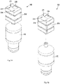
Fig. 1a is a perspective view of a wireless power supply and controller for a tattoo machine according to a preferred embodiment of the present invention, illustrated electrically connected to the tattoo machine; -
Fig. 1b is an exploded perspective view of the wireless power supply as inFig. 1a , illustrated with the wireless power supply separated from the tattoo machine; -
Fig. 2a is a side view of the wireless power supply as illustrated inFig. 1a ; -
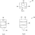
Fig. 3a is a top view of the wireless power supply according to the present invention and removed from the tattoo machine; -
Fig. 3b is a side view of the wireless power supply as illustrated inFig. 3a ; -
Fig. 3c is another side view of the wireless power supply as illustrated inFig. 3a ; and -
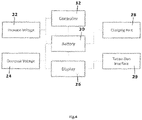
Fig. 4 is a block diagram illustrating the electronic components of the present invention. - A wireless power supply and voltage controller for a tattoo machine will be described with reference to
Figs. 1a to 4 of the accompanying drawings. More particularly, thewireless power supply 10 includes a body member having abattery housing 20 that includes arechargeable battery 30 and which includes an upinput button 22 and adown input button 24 for regulating a quantity of electrical voltage flowing to a motor of a tattoo machine. - The body member includes a
battery housing 20 having a plurality of walls that enclose and define an interior area configured to hold the various electronic components that will be described below. Thebattery housing 20 includes a top wall on which input controls and adisplay 26 may be positioned. - A
battery 30 is situated inside the interior area of thebattery housing 20 and, preferably, is rechargeable. For instance, aUSB port 28 may be mounted in a side wall of thebattery housing 20 and is electrically connected to thebattery 30 so that the battery may be recharged by a charger substantially similar to one used for charging a mobile phone or other rechargeable electronic device. - An
input selection assembly 21 is mounted atop a wall of thebattery housing 20, such as the top wall. In general, theinput selection assembly 21 is electrically connected to thebattery 30, is operable to adjust a quantity of voltage being transferred from thebattery 30, and is the means by which a user has direct control over setting a speed of atattoo machine 12. In an embodiment, theinput selection assembly 21 includes afirst input button 22 that is electrically connected to thebattery 30 in a manner that decreases voltage transfer and which, in effect, results in a slower motor speed when electrically connected to thetattoo machine 12. Technically, actuation of thefirst input button 22 may generate an electrical speed generation signal to the battery that is indicative of decreasing voltage by a predetermined amount, such as by one-half of a volt. Similarly, theinput selection assembly 21 includes asecond input button 24 that is electrically connected to thebattery 30 in a manner that increases voltage transfer and which, in effect, results in a faster motor speed when electrically connected to thetattoo machine 12. Technically, actuation of thesecond input button 24 may generate an electrical speed generation signal to the battery that is indicative of increasing voltage by a predetermined amount, such as by one-half of a volt. In actual implementation, an electronic controller 32 or pair of controllers may be electrically positioned intermediate theinput selection assembly 21 andbattery 30 and is operable to regulate an increase or decrease in voltage, respectively, according as may be selected by a user. - In a related aspect, the
input selection assembly 21 may include adigital display 26, such as an LCD display, positioned atop the top wall proximate to thefirst input button 22 andsecond input button 24. The input buttons are electrically connected to thedisplay 26 and thedisplay 26 may be electrically connected to thebattery 30, thedisplays 26 being operable to publish a current voltage being delivered from thebattery 30 to a motor of thetattoo machine 12. - According to the present invention, the
wireless power supply 10 includes anelectrical interface 29 that enables connection to a motor of atattoo machine 12. Theelectrical interface 29 may be an RCA plug as shown although other electronic connections are also contemplated and would also work. Specifically, theelectrical interface 29 has a first end electrically connected to thebattery 30 and a second end extending away from the first end and, in fact, outside of thebattery housing 20 for operable connection to thetattoo machine 12. - In use the
battery housing 20 with acharged battery 30 may be coupled to atattoo machine 12 via theinterface 29 as discussed above. Then, the speed of the motor of thetattoo machine 12 may be adjusted using the pair of voltage input buttons. - It is understood that while certain forms of this invention have been illustrated and described, it is not limited thereto except insofar as such limitations are included in the following claims and allowable functional equivalents thereof.
Claims (10)
- A wireless power supply and voltage controller for powering and controlling a tattoo machine, comprising:a battery housing having a plurality of walls that, collectively, define an interior area;a battery positioned in the interior area of said battery housing;an input selection assembly positioned on an exterior surface of a respective wall of said plurality of walls of said battery housing, said input selection assembly being operable to generate a speed generation signal;a controller electrically connected to said input selection assembly that is operable to regulate a quantity of voltage flowing from said battery according to said speed generation signal;an electrical interface having a first end electrically coupled to said battery and having a second end in electrical communication with said first end and extending away from said first end, characterized in that said second end extends away from said battery housing and is configured to operably and releasably be coupled directly to the tattoo machine without any wires hanging therebetween, in order to provide said voltage from said battery to said tattoo machine.
- The wireless power supply as in claim 1, wherein said electrical interface includes a RCA plug configured to selectively connect to the tattoo machine.
- The wireless power supply as in any of the preceding claims, wherein said input selection assembly includes:a first input button electrically connected to said controller and operable, when actuated,to generate said speed generation signal that is indicative of a decrease in voltage;a second input button electrically connected to said controller and operable, when actuated, to generate said speed generation signal that is indicative of an increase in voltage.
- The wireless power supply as in claim 3, wherein said input selection assembly includes a digital display positioned on the exterior surface of said respective wall of said battery housing, said digital display being electrically connected to said first and second input buttons and to said battery and operable to publish a selected voltage level.
- The wireless power supply as in any of the preceding claim, further comprising a charging port mounted on a respective wall of said battery housing and electrically connected to said battery, said charging port being configured to receive a USB charging cable.
- A system comprising:a tattoo machine; anda wireless power supply and voltage controller for powering and controlling said tattoo machine,wherein said wireless power supply and voltage controller comprises:a battery housing having a plurality of walls that, collectively, define an interior area;a battery positioned in the interior area of said battery housing;an input selection assembly positioned on an exterior surface of a respective wall of said plurality of walls of said battery housing, said input selection assembly being operable to generate a speed generation signal;a controller electrically connected to said input selection assembly that is operable to regulate a quantity of voltage flowing from said battery according to said speed generation signal; andan electrical interface having a first end electrically coupled to said battery and having a second end in electrical communication with said first end and extending away from said first end, characterized in that said second end extends away from said battery housing and is configured to operably and releasably be coupled directly to said tattoo machine without any wires hanging therebetween, in order to provide said voltage from said battery to said tattoo machine.
- The system of claim 6, wherein said electrical interface includes a RCA plug configured to selectively connect to said tattoo machine.
- The system of claim 6 or 7, wherein said input selection assembly includes:a first input button electrically connected to said controller and operable, when actuated, to generate said speed generation signal that is indicative of a decrease in voltage;a second input button electrically connected to said controller and operable, when actuated, to generate said speed generation signal that is indicative of an increase in voltage.
- The system of claim 8, wherein said input selection assembly includes a digital display positioned on the exterior surface of said respective wall of said battery housing, said digital display being electrically connected to said first and second input buttons and to said battery and operable to publish a selected voltage level.
- The system of any of claims 6-9, wherein said wireless power supply and voltage controller comprises a charging port mounted on a respective wall of said battery housing and electrically connected to said battery, said charging port being configured to receive a USB charging cable.
Applications Claiming Priority (3)
| Application Number | Priority Date | Filing Date | Title |
|---|---|---|---|
| US201862750254P | 2018-10-25 | 2018-10-25 | |
| US16/417,904 US10471246B1 (en) | 2018-10-25 | 2019-05-21 | Wireless power supply and speed controller for tattoo machine |
| PCT/US2019/062205 WO2020236214A1 (en) | 2018-10-25 | 2019-11-19 | Wireless power supply and speed controller for tattoo machine |
Publications (3)
| Publication Number | Publication Date |
|---|---|
| EP3773859A1 EP3773859A1 (en) | 2021-02-17 |
| EP3773859A4 EP3773859A4 (en) | 2021-05-26 |
| EP3773859B1 true EP3773859B1 (en) | 2023-01-25 |
Family
ID=68466133
Family Applications (1)
| Application Number | Title | Priority Date | Filing Date |
|---|---|---|---|
| EP19927566.0A Active EP3773859B1 (en) | 2018-10-25 | 2019-11-19 | Wireless power supply and speed controller for tattoo machine |
Country Status (7)
| Country | Link |
|---|---|
| US (1) | US10471246B1 (en) |
| EP (1) | EP3773859B1 (en) |
| CN (1) | CN112272573A (en) |
| AU (1) | AU2019359618B1 (en) |
| CA (1) | CA3073407C (en) |
| ES (1) | ES2942908T3 (en) |
| WO (1) | WO2020236214A1 (en) |
Families Citing this family (19)
| Publication number | Priority date | Publication date | Assignee | Title |
|---|---|---|---|---|
| EP3949075A1 (en) | 2019-03-27 | 2022-02-09 | FK Irons Inc. | Tattoo machine rechargeable battery unit with voltage controller |
| AU2020412957A1 (en) * | 2019-12-23 | 2022-07-14 | Inkjecta Pty Ltd | A tattoo machine power supply |
| US11957861B2 (en) | 2020-01-28 | 2024-04-16 | Fk Irons Inc. | Pen style wireless tattoo machine, system, and kits |
| WO2021178577A1 (en) * | 2020-03-03 | 2021-09-10 | Fk Irons Inc. | Device for offset wireless tattoo battery pack and methods of use |
| USD960085S1 (en) | 2020-03-03 | 2022-08-09 | Fk Irons Inc. | Tattoo machine battery power supply |
| US12257412B2 (en) | 2020-05-14 | 2025-03-25 | Ink Projects Llc | Wireless tattoo device |
| US12011563B2 (en) | 2020-06-19 | 2024-06-18 | Fk Irons Inc. | Devices and methods for controlling needle reciprocation |
| USD910846S1 (en) | 2020-06-22 | 2021-02-16 | Fk Irons Inc. | Tattoo machine |
| USD1060666S1 (en) | 2021-02-12 | 2025-02-04 | Fk Irons Inc. | Combined adapter device and grip for a tattoo machine |
| WO2022174097A1 (en) * | 2021-02-12 | 2022-08-18 | Fk Irons Inc. | Adapter device for tattoo machine |
| US12011564B2 (en) | 2021-08-09 | 2024-06-18 | Long Xiao | Handheld tattoo device with integrated battery power source, control circuitry, and user interface with touch sensor |
| USD1025357S1 (en) | 2021-09-30 | 2024-04-30 | Fk Irons Inc. | Tattoo machine |
| USD1031985S1 (en) * | 2022-08-15 | 2024-06-18 | Hangzhou Wormhole Import and Export Trading Co., Ltd. | Wireless power supply tattoo pen |
| USD1017806S1 (en) * | 2022-08-15 | 2024-03-12 | Hangzhou Wormhole Import and Export Trading Co., Ltd. | Wireless power supply tattoo pen |
| USD1016285S1 (en) * | 2022-08-15 | 2024-02-27 | Hangzhou Wormhole Import and Export Trading Co., Ltd. | Wireless power supply tattoo pen |
| USD1031986S1 (en) * | 2022-08-15 | 2024-06-18 | Hangzhou Wormhole Import and Export Trading Co., Ltd. | Wireless power supply tattoo pen |
| CN220676537U (en) * | 2022-11-22 | 2024-03-29 | 象牌纹身供应品公司 | Tattoo machine for use with wireless battery power |
| US12465738B2 (en) * | 2022-11-22 | 2025-11-11 | Bishop Tattoo Supply, Inc. | Tattoo machine with magnetic and friction power source connector |
| USD1066666S1 (en) | 2023-05-25 | 2025-03-11 | Fk Irons Inc. | Tattoo machine |
Family Cites Families (10)
| Publication number | Priority date | Publication date | Assignee | Title |
|---|---|---|---|---|
| US6550356B1 (en) * | 1999-09-18 | 2003-04-22 | Keith A. Underwood | Tattoo technology |
| US9433767B2 (en) * | 2007-06-01 | 2016-09-06 | Brett Colton | Wireless tattoo applicator system |
| US20100072827A1 (en) * | 2008-09-22 | 2010-03-25 | Norstrom Brian R | Mobile power source for use with a hand-held machine and method of operating |
| US8228666B2 (en) * | 2009-03-17 | 2012-07-24 | Timothy Garett Rickard | Retrofit control system and power supply for a tattoo gun |
| US11547539B2 (en) * | 2010-06-21 | 2023-01-10 | Steven Gagliano | Power varying pedal |
| US20120024114A1 (en) | 2010-07-31 | 2012-02-02 | Alejandro Vazquez | Battery operated tattoo gun |
| CN202395478U (en) * | 2011-12-09 | 2012-08-22 | 天津光电通信技术有限公司 | Portable wireless chargeable tattooing machine power supply |
| US10220196B2 (en) | 2013-12-18 | 2019-03-05 | Ink Machines Sweden Ab | Tattoo machine power supply |
| ITUA20163386A1 (en) | 2016-05-12 | 2017-11-12 | One Way Tattoo | Direct current variable voltage power supply |
| US10898704B2 (en) * | 2016-08-12 | 2021-01-26 | Bishop Tattoo Supply, Inc. | Tattoo machine having an arm-mounted power supply |
-
2019
- 2019-05-21 US US16/417,904 patent/US10471246B1/en active Active
- 2019-11-19 CN CN201980005150.2A patent/CN112272573A/en active Pending
- 2019-11-19 AU AU2019359618A patent/AU2019359618B1/en active Active
- 2019-11-19 CA CA3073407A patent/CA3073407C/en active Active
- 2019-11-19 ES ES19927566T patent/ES2942908T3/en active Active
- 2019-11-19 EP EP19927566.0A patent/EP3773859B1/en active Active
- 2019-11-19 WO PCT/US2019/062205 patent/WO2020236214A1/en not_active Ceased
Also Published As
| Publication number | Publication date |
|---|---|
| CA3073407A1 (en) | 2020-11-21 |
| ES2942908T3 (en) | 2023-06-07 |
| EP3773859A1 (en) | 2021-02-17 |
| CA3073407C (en) | 2022-07-19 |
| US10471246B1 (en) | 2019-11-12 |
| AU2019359618B1 (en) | 2020-05-21 |
| CN112272573A (en) | 2021-01-26 |
| EP3773859A4 (en) | 2021-05-26 |
| WO2020236214A1 (en) | 2020-11-26 |
Similar Documents
| Publication | Publication Date | Title |
|---|---|---|
| EP3773859B1 (en) | Wireless power supply and speed controller for tattoo machine | |
| US11812836B2 (en) | Electronic nail file with digital control and display and system of operation | |
| KR101669181B1 (en) | Transcutaneous Electrical Nerve Stimulation(TENS) apparatus | |
| EP2602064B1 (en) | Electric tool system | |
| US11059118B2 (en) | Cordless soldering iron | |
| EP3348314B1 (en) | Operation system, game system, and game controller capable of identifying connected device with simplified scheme | |
| JP7804205B2 (en) | Garments and Systems | |
| US12415059B2 (en) | Device for offset wireless tattoo battery pack and methods of use | |
| JP2024050852A (en) | Battery packs, devices, clothing, and electrical equipment | |
| CN101150327A (en) | Portable equipment borrowing system and portable equipment | |
| KR20130006884U (en) | Secondary battery with a charging data cable | |
| JP2021175353A5 (en) | ||
| US20220278539A1 (en) | Technique for controlling voltage to be supplied to electric appliance | |
| CN207220168U (en) | Electronic cigarette and wireless charging device | |
| KR20100009567U (en) | Portable low-frequency electrotherapy apparatus | |
| KR20170108391A (en) | Portable wireless hair clipper with a rechargeable battery | |
| JP2002315223A (en) | DC power supply with charging function | |
| EP4646964A1 (en) | Electronic nail file with rechargeable charging base | |
| JP2004180464A (en) | DC power supply | |
| JP3100192U (en) | Charger | |
| JPH099839A (en) | Electric source-charging apparatus for fishing electrically-driven reel and electric source apparatus | |
| KR19990040699U (en) | Charge / discharge integrated power supply and portable computer including the same | |
| CN116458019A (en) | Power supply device, method, and program for analyzing power specifications of connected electronic device | |
| KR20200070781A (en) | Computer case with selectable quick charging and operating method | |
| KR20150120129A (en) | Multi-functional Controller of Surface Heat Generating Apparatus |
Legal Events
| Date | Code | Title | Description |
|---|---|---|---|
| STAA | Information on the status of an ep patent application or granted ep patent |
Free format text: STATUS: UNKNOWN |
|
| STAA | Information on the status of an ep patent application or granted ep patent |
Free format text: STATUS: THE INTERNATIONAL PUBLICATION HAS BEEN MADE |
|
| PUAI | Public reference made under article 153(3) epc to a published international application that has entered the european phase |
Free format text: ORIGINAL CODE: 0009012 |
|
| STAA | Information on the status of an ep patent application or granted ep patent |
Free format text: STATUS: REQUEST FOR EXAMINATION WAS MADE |
|
| 17P | Request for examination filed |
Effective date: 20201109 |
|
| AK | Designated contracting states |
Kind code of ref document: A1 Designated state(s): AL AT BE BG CH CY CZ DE DK EE ES FI FR GB GR HR HU IE IS IT LI LT LU LV MC MK MT NL NO PL PT RO RS SE SI SK SM TR |
|
| AX | Request for extension of the european patent |
Extension state: BA ME |
|
| A4 | Supplementary search report drawn up and despatched |
Effective date: 20210426 |
|
| RIC1 | Information provided on ipc code assigned before grant |
Ipc: A61M 37/00 20060101AFI20210420BHEP Ipc: A61B 17/20 20060101ALI20210420BHEP Ipc: A61B 17/00 20060101ALI20210420BHEP Ipc: A61B 17/072 20060101ALI20210420BHEP Ipc: A61B 17/34 20060101ALI20210420BHEP |
|
| GRAP | Despatch of communication of intention to grant a patent |
Free format text: ORIGINAL CODE: EPIDOSNIGR1 |
|
| STAA | Information on the status of an ep patent application or granted ep patent |
Free format text: STATUS: GRANT OF PATENT IS INTENDED |
|
| DAV | Request for validation of the european patent (deleted) | ||
| DAX | Request for extension of the european patent (deleted) | ||
| INTG | Intention to grant announced |
Effective date: 20220405 |
|
| GRAJ | Information related to disapproval of communication of intention to grant by the applicant or resumption of examination proceedings by the epo deleted |
Free format text: ORIGINAL CODE: EPIDOSDIGR1 |
|
| STAA | Information on the status of an ep patent application or granted ep patent |
Free format text: STATUS: REQUEST FOR EXAMINATION WAS MADE |
|
| INTC | Intention to grant announced (deleted) | ||
| GRAP | Despatch of communication of intention to grant a patent |
Free format text: ORIGINAL CODE: EPIDOSNIGR1 |
|
| STAA | Information on the status of an ep patent application or granted ep patent |
Free format text: STATUS: GRANT OF PATENT IS INTENDED |
|
| INTG | Intention to grant announced |
Effective date: 20221031 |
|
| GRAS | Grant fee paid |
Free format text: ORIGINAL CODE: EPIDOSNIGR3 |
|
| GRAA | (expected) grant |
Free format text: ORIGINAL CODE: 0009210 |
|
| STAA | Information on the status of an ep patent application or granted ep patent |
Free format text: STATUS: THE PATENT HAS BEEN GRANTED |
|
| AK | Designated contracting states |
Kind code of ref document: B1 Designated state(s): AL AT BE BG CH CY CZ DE DK EE ES FI FR GB GR HR HU IE IS IT LI LT LU LV MC MK MT NL NO PL PT RO RS SE SI SK SM TR |
|
| REG | Reference to a national code |
Ref country code: GB Ref legal event code: FG4D |
|
| REG | Reference to a national code |
Ref country code: CH Ref legal event code: EP |
|
| REG | Reference to a national code |
Ref country code: DE Ref legal event code: R096 Ref document number: 602019024967 Country of ref document: DE |
|
| REG | Reference to a national code |
Ref country code: AT Ref legal event code: REF Ref document number: 1545529 Country of ref document: AT Kind code of ref document: T Effective date: 20230215 Ref country code: IE Ref legal event code: FG4D |
|
| REG | Reference to a national code |
Ref country code: NL Ref legal event code: FP |
|
| REG | Reference to a national code |
Ref country code: LT Ref legal event code: MG9D |
|
| REG | Reference to a national code |
Ref country code: ES Ref legal event code: FG2A Ref document number: 2942908 Country of ref document: ES Kind code of ref document: T3 Effective date: 20230607 |
|
| REG | Reference to a national code |
Ref country code: AT Ref legal event code: MK05 Ref document number: 1545529 Country of ref document: AT Kind code of ref document: T Effective date: 20230125 |
|
| PG25 | Lapsed in a contracting state [announced via postgrant information from national office to epo] |
Ref country code: RS Free format text: LAPSE BECAUSE OF FAILURE TO SUBMIT A TRANSLATION OF THE DESCRIPTION OR TO PAY THE FEE WITHIN THE PRESCRIBED TIME-LIMIT Effective date: 20230125 Ref country code: PT Free format text: LAPSE BECAUSE OF FAILURE TO SUBMIT A TRANSLATION OF THE DESCRIPTION OR TO PAY THE FEE WITHIN THE PRESCRIBED TIME-LIMIT Effective date: 20230525 Ref country code: NO Free format text: LAPSE BECAUSE OF FAILURE TO SUBMIT A TRANSLATION OF THE DESCRIPTION OR TO PAY THE FEE WITHIN THE PRESCRIBED TIME-LIMIT Effective date: 20230425 Ref country code: LV Free format text: LAPSE BECAUSE OF FAILURE TO SUBMIT A TRANSLATION OF THE DESCRIPTION OR TO PAY THE FEE WITHIN THE PRESCRIBED TIME-LIMIT Effective date: 20230125 Ref country code: LT Free format text: LAPSE BECAUSE OF FAILURE TO SUBMIT A TRANSLATION OF THE DESCRIPTION OR TO PAY THE FEE WITHIN THE PRESCRIBED TIME-LIMIT Effective date: 20230125 Ref country code: HR Free format text: LAPSE BECAUSE OF FAILURE TO SUBMIT A TRANSLATION OF THE DESCRIPTION OR TO PAY THE FEE WITHIN THE PRESCRIBED TIME-LIMIT Effective date: 20230125 Ref country code: AT Free format text: LAPSE BECAUSE OF FAILURE TO SUBMIT A TRANSLATION OF THE DESCRIPTION OR TO PAY THE FEE WITHIN THE PRESCRIBED TIME-LIMIT Effective date: 20230125 |
|
| PG25 | Lapsed in a contracting state [announced via postgrant information from national office to epo] |
Ref country code: SE Free format text: LAPSE BECAUSE OF FAILURE TO SUBMIT A TRANSLATION OF THE DESCRIPTION OR TO PAY THE FEE WITHIN THE PRESCRIBED TIME-LIMIT Effective date: 20230125 Ref country code: PL Free format text: LAPSE BECAUSE OF FAILURE TO SUBMIT A TRANSLATION OF THE DESCRIPTION OR TO PAY THE FEE WITHIN THE PRESCRIBED TIME-LIMIT Effective date: 20230125 Ref country code: IS Free format text: LAPSE BECAUSE OF FAILURE TO SUBMIT A TRANSLATION OF THE DESCRIPTION OR TO PAY THE FEE WITHIN THE PRESCRIBED TIME-LIMIT Effective date: 20230525 Ref country code: GR Free format text: LAPSE BECAUSE OF FAILURE TO SUBMIT A TRANSLATION OF THE DESCRIPTION OR TO PAY THE FEE WITHIN THE PRESCRIBED TIME-LIMIT Effective date: 20230426 Ref country code: FI Free format text: LAPSE BECAUSE OF FAILURE TO SUBMIT A TRANSLATION OF THE DESCRIPTION OR TO PAY THE FEE WITHIN THE PRESCRIBED TIME-LIMIT Effective date: 20230125 |
|
| REG | Reference to a national code |
Ref country code: DE Ref legal event code: R097 Ref document number: 602019024967 Country of ref document: DE |
|
| PG25 | Lapsed in a contracting state [announced via postgrant information from national office to epo] |
Ref country code: SM Free format text: LAPSE BECAUSE OF FAILURE TO SUBMIT A TRANSLATION OF THE DESCRIPTION OR TO PAY THE FEE WITHIN THE PRESCRIBED TIME-LIMIT Effective date: 20230125 Ref country code: RO Free format text: LAPSE BECAUSE OF FAILURE TO SUBMIT A TRANSLATION OF THE DESCRIPTION OR TO PAY THE FEE WITHIN THE PRESCRIBED TIME-LIMIT Effective date: 20230125 Ref country code: EE Free format text: LAPSE BECAUSE OF FAILURE TO SUBMIT A TRANSLATION OF THE DESCRIPTION OR TO PAY THE FEE WITHIN THE PRESCRIBED TIME-LIMIT Effective date: 20230125 Ref country code: DK Free format text: LAPSE BECAUSE OF FAILURE TO SUBMIT A TRANSLATION OF THE DESCRIPTION OR TO PAY THE FEE WITHIN THE PRESCRIBED TIME-LIMIT Effective date: 20230125 Ref country code: CZ Free format text: LAPSE BECAUSE OF FAILURE TO SUBMIT A TRANSLATION OF THE DESCRIPTION OR TO PAY THE FEE WITHIN THE PRESCRIBED TIME-LIMIT Effective date: 20230125 |
|
| PG25 | Lapsed in a contracting state [announced via postgrant information from national office to epo] |
Ref country code: SK Free format text: LAPSE BECAUSE OF FAILURE TO SUBMIT A TRANSLATION OF THE DESCRIPTION OR TO PAY THE FEE WITHIN THE PRESCRIBED TIME-LIMIT Effective date: 20230125 |
|
| PLBE | No opposition filed within time limit |
Free format text: ORIGINAL CODE: 0009261 |
|
| STAA | Information on the status of an ep patent application or granted ep patent |
Free format text: STATUS: NO OPPOSITION FILED WITHIN TIME LIMIT |
|
| 26N | No opposition filed |
Effective date: 20231026 |
|
| PG25 | Lapsed in a contracting state [announced via postgrant information from national office to epo] |
Ref country code: SI Free format text: LAPSE BECAUSE OF FAILURE TO SUBMIT A TRANSLATION OF THE DESCRIPTION OR TO PAY THE FEE WITHIN THE PRESCRIBED TIME-LIMIT Effective date: 20230125 |
|
| REG | Reference to a national code |
Ref country code: CH Ref legal event code: PL |
|
| PG25 | Lapsed in a contracting state [announced via postgrant information from national office to epo] |
Ref country code: MC Free format text: LAPSE BECAUSE OF FAILURE TO SUBMIT A TRANSLATION OF THE DESCRIPTION OR TO PAY THE FEE WITHIN THE PRESCRIBED TIME-LIMIT Effective date: 20230125 |
|
| PG25 | Lapsed in a contracting state [announced via postgrant information from national office to epo] |
Ref country code: LU Free format text: LAPSE BECAUSE OF NON-PAYMENT OF DUE FEES Effective date: 20231119 |
|
| PG25 | Lapsed in a contracting state [announced via postgrant information from national office to epo] |
Ref country code: CH Free format text: LAPSE BECAUSE OF NON-PAYMENT OF DUE FEES Effective date: 20231130 |
|
| PG25 | Lapsed in a contracting state [announced via postgrant information from national office to epo] |
Ref country code: MC Free format text: LAPSE BECAUSE OF FAILURE TO SUBMIT A TRANSLATION OF THE DESCRIPTION OR TO PAY THE FEE WITHIN THE PRESCRIBED TIME-LIMIT Effective date: 20230125 Ref country code: LU Free format text: LAPSE BECAUSE OF NON-PAYMENT OF DUE FEES Effective date: 20231119 Ref country code: CH Free format text: LAPSE BECAUSE OF NON-PAYMENT OF DUE FEES Effective date: 20231130 |
|
| REG | Reference to a national code |
Ref country code: BE Ref legal event code: MM Effective date: 20231130 |
|
| REG | Reference to a national code |
Ref country code: IE Ref legal event code: MM4A |
|
| PG25 | Lapsed in a contracting state [announced via postgrant information from national office to epo] |
Ref country code: IE Free format text: LAPSE BECAUSE OF NON-PAYMENT OF DUE FEES Effective date: 20231119 |
|
| PG25 | Lapsed in a contracting state [announced via postgrant information from national office to epo] |
Ref country code: BE Free format text: LAPSE BECAUSE OF NON-PAYMENT OF DUE FEES Effective date: 20231130 |
|
| PG25 | Lapsed in a contracting state [announced via postgrant information from national office to epo] |
Ref country code: IE Free format text: LAPSE BECAUSE OF NON-PAYMENT OF DUE FEES Effective date: 20231119 Ref country code: BE Free format text: LAPSE BECAUSE OF NON-PAYMENT OF DUE FEES Effective date: 20231130 |
|
| PG25 | Lapsed in a contracting state [announced via postgrant information from national office to epo] |
Ref country code: BG Free format text: LAPSE BECAUSE OF FAILURE TO SUBMIT A TRANSLATION OF THE DESCRIPTION OR TO PAY THE FEE WITHIN THE PRESCRIBED TIME-LIMIT Effective date: 20230125 |
|
| PG25 | Lapsed in a contracting state [announced via postgrant information from national office to epo] |
Ref country code: BG Free format text: LAPSE BECAUSE OF FAILURE TO SUBMIT A TRANSLATION OF THE DESCRIPTION OR TO PAY THE FEE WITHIN THE PRESCRIBED TIME-LIMIT Effective date: 20230125 |
|
| PG25 | Lapsed in a contracting state [announced via postgrant information from national office to epo] |
Ref country code: CY Free format text: LAPSE BECAUSE OF FAILURE TO SUBMIT A TRANSLATION OF THE DESCRIPTION OR TO PAY THE FEE WITHIN THE PRESCRIBED TIME-LIMIT; INVALID AB INITIO Effective date: 20191119 |
|
| PG25 | Lapsed in a contracting state [announced via postgrant information from national office to epo] |
Ref country code: HU Free format text: LAPSE BECAUSE OF FAILURE TO SUBMIT A TRANSLATION OF THE DESCRIPTION OR TO PAY THE FEE WITHIN THE PRESCRIBED TIME-LIMIT; INVALID AB INITIO Effective date: 20191119 |
|
| PG25 | Lapsed in a contracting state [announced via postgrant information from national office to epo] |
Ref country code: TR Free format text: LAPSE BECAUSE OF FAILURE TO SUBMIT A TRANSLATION OF THE DESCRIPTION OR TO PAY THE FEE WITHIN THE PRESCRIBED TIME-LIMIT Effective date: 20230125 |
|
| PGFP | Annual fee paid to national office [announced via postgrant information from national office to epo] |
Ref country code: NL Payment date: 20251119 Year of fee payment: 7 |
|
| PGFP | Annual fee paid to national office [announced via postgrant information from national office to epo] |
Ref country code: DE Payment date: 20251118 Year of fee payment: 7 |
|
| PGFP | Annual fee paid to national office [announced via postgrant information from national office to epo] |
Ref country code: GB Payment date: 20251120 Year of fee payment: 7 |
|
| PGFP | Annual fee paid to national office [announced via postgrant information from national office to epo] |
Ref country code: IT Payment date: 20251128 Year of fee payment: 7 |
|
| PGFP | Annual fee paid to national office [announced via postgrant information from national office to epo] |
Ref country code: FR Payment date: 20251120 Year of fee payment: 7 |
|
| PGFP | Annual fee paid to national office [announced via postgrant information from national office to epo] |
Ref country code: ES Payment date: 20251216 Year of fee payment: 7 |