EP3773333B1 - Injector assembly employing compressed gas and a mechanical brake for presenting an intraocular lens to a patient - Google Patents
Injector assembly employing compressed gas and a mechanical brake for presenting an intraocular lens to a patient Download PDFInfo
- Publication number
- EP3773333B1 EP3773333B1 EP19722226.8A EP19722226A EP3773333B1 EP 3773333 B1 EP3773333 B1 EP 3773333B1 EP 19722226 A EP19722226 A EP 19722226A EP 3773333 B1 EP3773333 B1 EP 3773333B1
- Authority
- EP
- European Patent Office
- Prior art keywords
- guide shaft
- shaft assembly
- iol
- compressed gas
- injector
- Prior art date
- Legal status (The legal status is an assumption and is not a legal conclusion. Google has not performed a legal analysis and makes no representation as to the accuracy of the status listed.)
- Active
Links
Images


Classifications
-
- A—HUMAN NECESSITIES
- A61—MEDICAL OR VETERINARY SCIENCE; HYGIENE
- A61F—FILTERS IMPLANTABLE INTO BLOOD VESSELS; PROSTHESES; DEVICES PROVIDING PATENCY TO, OR PREVENTING COLLAPSING OF, TUBULAR STRUCTURES OF THE BODY, e.g. STENTS; ORTHOPAEDIC, NURSING OR CONTRACEPTIVE DEVICES; FOMENTATION; TREATMENT OR PROTECTION OF EYES OR EARS; BANDAGES, DRESSINGS OR ABSORBENT PADS; FIRST-AID KITS
- A61F2/00—Filters implantable into blood vessels; Prostheses, i.e. artificial substitutes or replacements for parts of the body; Appliances for connecting them with the body; Devices providing patency to, or preventing collapsing of, tubular structures of the body, e.g. stents
- A61F2/02—Prostheses implantable into the body
- A61F2/14—Eye parts, e.g. lenses or corneal implants; Artificial eyes
- A61F2/16—Intraocular lenses
- A61F2/1662—Instruments for inserting intraocular lenses into the eye
- A61F2/167—Instruments for inserting intraocular lenses into the eye with pushable plungers
-
- A—HUMAN NECESSITIES
- A61—MEDICAL OR VETERINARY SCIENCE; HYGIENE
- A61F—FILTERS IMPLANTABLE INTO BLOOD VESSELS; PROSTHESES; DEVICES PROVIDING PATENCY TO, OR PREVENTING COLLAPSING OF, TUBULAR STRUCTURES OF THE BODY, e.g. STENTS; ORTHOPAEDIC, NURSING OR CONTRACEPTIVE DEVICES; FOMENTATION; TREATMENT OR PROTECTION OF EYES OR EARS; BANDAGES, DRESSINGS OR ABSORBENT PADS; FIRST-AID KITS
- A61F2/00—Filters implantable into blood vessels; Prostheses, i.e. artificial substitutes or replacements for parts of the body; Appliances for connecting them with the body; Devices providing patency to, or preventing collapsing of, tubular structures of the body, e.g. stents
- A61F2/02—Prostheses implantable into the body
- A61F2/14—Eye parts, e.g. lenses or corneal implants; Artificial eyes
- A61F2/16—Intraocular lenses
- A61F2/1662—Instruments for inserting intraocular lenses into the eye
-
- A—HUMAN NECESSITIES
- A61—MEDICAL OR VETERINARY SCIENCE; HYGIENE
- A61B—DIAGNOSIS; SURGERY; IDENTIFICATION
- A61B90/00—Instruments, implements or accessories specially adapted for surgery or diagnosis and not covered by any of the groups A61B1/00 - A61B50/00, e.g. for luxation treatment or for protecting wound edges
- A61B90/03—Automatic limiting or abutting means, e.g. for safety
-
- A—HUMAN NECESSITIES
- A61—MEDICAL OR VETERINARY SCIENCE; HYGIENE
- A61F—FILTERS IMPLANTABLE INTO BLOOD VESSELS; PROSTHESES; DEVICES PROVIDING PATENCY TO, OR PREVENTING COLLAPSING OF, TUBULAR STRUCTURES OF THE BODY, e.g. STENTS; ORTHOPAEDIC, NURSING OR CONTRACEPTIVE DEVICES; FOMENTATION; TREATMENT OR PROTECTION OF EYES OR EARS; BANDAGES, DRESSINGS OR ABSORBENT PADS; FIRST-AID KITS
- A61F2/00—Filters implantable into blood vessels; Prostheses, i.e. artificial substitutes or replacements for parts of the body; Appliances for connecting them with the body; Devices providing patency to, or preventing collapsing of, tubular structures of the body, e.g. stents
- A61F2/02—Prostheses implantable into the body
- A61F2/14—Eye parts, e.g. lenses or corneal implants; Artificial eyes
- A61F2/16—Intraocular lenses
- A61F2/1662—Instruments for inserting intraocular lenses into the eye
- A61F2/1672—Instruments for inserting intraocular lenses into the eye with a two-stage plunger, e.g. rotatable and pushable or rotatable at different speeds
-
- A—HUMAN NECESSITIES
- A61—MEDICAL OR VETERINARY SCIENCE; HYGIENE
- A61F—FILTERS IMPLANTABLE INTO BLOOD VESSELS; PROSTHESES; DEVICES PROVIDING PATENCY TO, OR PREVENTING COLLAPSING OF, TUBULAR STRUCTURES OF THE BODY, e.g. STENTS; ORTHOPAEDIC, NURSING OR CONTRACEPTIVE DEVICES; FOMENTATION; TREATMENT OR PROTECTION OF EYES OR EARS; BANDAGES, DRESSINGS OR ABSORBENT PADS; FIRST-AID KITS
- A61F9/00—Methods or devices for treatment of the eyes; Devices for putting in contact-lenses; Devices to correct squinting; Apparatus to guide the blind; Protective devices for the eyes, carried on the body or in the hand
- A61F9/007—Methods or devices for eye surgery
- A61F9/00736—Instruments for removal of intra-ocular material or intra-ocular injection, e.g. cataract instruments
-
- A—HUMAN NECESSITIES
- A61—MEDICAL OR VETERINARY SCIENCE; HYGIENE
- A61B—DIAGNOSIS; SURGERY; IDENTIFICATION
- A61B17/00—Surgical instruments, devices or methods
- A61B2017/00367—Details of actuation of instruments, e.g. relations between pushing buttons, or the like, and activation of the tool, working tip, or the like
-
- A—HUMAN NECESSITIES
- A61—MEDICAL OR VETERINARY SCIENCE; HYGIENE
- A61B—DIAGNOSIS; SURGERY; IDENTIFICATION
- A61B17/00—Surgical instruments, devices or methods
- A61B2017/00367—Details of actuation of instruments, e.g. relations between pushing buttons, or the like, and activation of the tool, working tip, or the like
- A61B2017/00398—Details of actuation of instruments, e.g. relations between pushing buttons, or the like, and activation of the tool, working tip, or the like using powered actuators, e.g. stepper motors, solenoids
-
- A—HUMAN NECESSITIES
- A61—MEDICAL OR VETERINARY SCIENCE; HYGIENE
- A61B—DIAGNOSIS; SURGERY; IDENTIFICATION
- A61B90/00—Instruments, implements or accessories specially adapted for surgery or diagnosis and not covered by any of the groups A61B1/00 - A61B50/00, e.g. for luxation treatment or for protecting wound edges
- A61B90/03—Automatic limiting or abutting means, e.g. for safety
- A61B2090/033—Abutting means, stops, e.g. abutting on tissue or skin
- A61B2090/034—Abutting means, stops, e.g. abutting on tissue or skin abutting on parts of the device itself
-
- A—HUMAN NECESSITIES
- A61—MEDICAL OR VETERINARY SCIENCE; HYGIENE
- A61F—FILTERS IMPLANTABLE INTO BLOOD VESSELS; PROSTHESES; DEVICES PROVIDING PATENCY TO, OR PREVENTING COLLAPSING OF, TUBULAR STRUCTURES OF THE BODY, e.g. STENTS; ORTHOPAEDIC, NURSING OR CONTRACEPTIVE DEVICES; FOMENTATION; TREATMENT OR PROTECTION OF EYES OR EARS; BANDAGES, DRESSINGS OR ABSORBENT PADS; FIRST-AID KITS
- A61F2/00—Filters implantable into blood vessels; Prostheses, i.e. artificial substitutes or replacements for parts of the body; Appliances for connecting them with the body; Devices providing patency to, or preventing collapsing of, tubular structures of the body, e.g. stents
- A61F2/02—Prostheses implantable into the body
- A61F2/14—Eye parts, e.g. lenses or corneal implants; Artificial eyes
- A61F2/148—Implantation instruments specially adapted therefor
-
- A—HUMAN NECESSITIES
- A61—MEDICAL OR VETERINARY SCIENCE; HYGIENE
- A61F—FILTERS IMPLANTABLE INTO BLOOD VESSELS; PROSTHESES; DEVICES PROVIDING PATENCY TO, OR PREVENTING COLLAPSING OF, TUBULAR STRUCTURES OF THE BODY, e.g. STENTS; ORTHOPAEDIC, NURSING OR CONTRACEPTIVE DEVICES; FOMENTATION; TREATMENT OR PROTECTION OF EYES OR EARS; BANDAGES, DRESSINGS OR ABSORBENT PADS; FIRST-AID KITS
- A61F2/00—Filters implantable into blood vessels; Prostheses, i.e. artificial substitutes or replacements for parts of the body; Appliances for connecting them with the body; Devices providing patency to, or preventing collapsing of, tubular structures of the body, e.g. stents
- A61F2/02—Prostheses implantable into the body
- A61F2/14—Eye parts, e.g. lenses or corneal implants; Artificial eyes
- A61F2/16—Intraocular lenses
- A61F2/1662—Instruments for inserting intraocular lenses into the eye
- A61F2/1664—Instruments for inserting intraocular lenses into the eye for manual insertion during surgery, e.g. forceps-like instruments
-
- A—HUMAN NECESSITIES
- A61—MEDICAL OR VETERINARY SCIENCE; HYGIENE
- A61F—FILTERS IMPLANTABLE INTO BLOOD VESSELS; PROSTHESES; DEVICES PROVIDING PATENCY TO, OR PREVENTING COLLAPSING OF, TUBULAR STRUCTURES OF THE BODY, e.g. STENTS; ORTHOPAEDIC, NURSING OR CONTRACEPTIVE DEVICES; FOMENTATION; TREATMENT OR PROTECTION OF EYES OR EARS; BANDAGES, DRESSINGS OR ABSORBENT PADS; FIRST-AID KITS
- A61F2/00—Filters implantable into blood vessels; Prostheses, i.e. artificial substitutes or replacements for parts of the body; Appliances for connecting them with the body; Devices providing patency to, or preventing collapsing of, tubular structures of the body, e.g. stents
- A61F2/02—Prostheses implantable into the body
- A61F2/14—Eye parts, e.g. lenses or corneal implants; Artificial eyes
- A61F2/16—Intraocular lenses
- A61F2/1662—Instruments for inserting intraocular lenses into the eye
- A61F2/1678—Instruments for inserting intraocular lenses into the eye with a separate cartridge or other lens setting part for storage of a lens, e.g. preloadable for shipping
Definitions
- the present disclosure relates to an intraocular lens (IOL) injector and particularly to an IOL injector using compressed gas as a motive force for presenting an IOL to a patient, and more particularly to a disposable IOL injector using compressed gas as the motive force.
- IOL intraocular lens
- Intraocular lenses are artificial lenses used to replace natural crystalline lenses of eyes when the natural lenses are diseased or otherwise impaired. Under some circumstances a natural lens may remain in an eye together with an implanted IOL. IOLs may be placed in either the posterior chamber or the anterior chamber of an eye.
- IOLs come in a variety of structures and materials.
- Various instruments and methods for implanting such IOLs in an eye are known.
- an incision is made in a cornea and an IOL is inserted into the eye through the incision.
- a surgeon uses surgical forceps to grasp the IOL and insert it through the incision into the eye. While this technique is still practiced today, more and more surgeons are using IOL injectors which can offer advantages such as affording a surgeon more control when inserting an IOL into an eye and permitting insertion of IOLs through smaller incisions.
- Smaller incision sizes e.g., less than about 3 mm
- larger incisions e.g., about 3.2 to 5+ mm
- smaller incisions have been associated with reduced post-surgical healing time and reduced complications such as induced astigmatism.
- an IOL be expelled from the tip of the IOL injector and into the eye in an undamaged condition in a predictable orientation, with a predictable speed and force.
- IOL injectors are known e.g. from US2015/0342726 A1 and US2014/0276901 A1 .
- the present disclosure provides an IOL injector for single hand control, manipulation and operation, and in select configurations the IOL injector is single use or disposable. That is, the present construction and application of compressed gas as the motive force provides sufficient cost savings to render the IOL injector disposable.
- the present disclosure also provides an intraocular lens, (IOL) injector having a compressed gas reservoir for retaining a compressed gas; a guide shaft assembly exposed to the compressed gas reservoir, the guide shaft assembly being moveable along a longitudinal direction from a retracted position to an extended position; and a mechanical brake operably coupled to the guide shaft assembly, the mechanical brake being configured to exert on the guide shaft assembly, in response to an operator actuation, a variable resistance to the longitudinal movement of the guide shaft, the mechanical brake having a default engagement with the guide shaft assembly sufficient to preclude movement of the guide shaft assembly in response to exposure of the guide shaft assembly to compressed gas in the compressed gas reservoir.
- IOL intraocular lens
- the present disclosure further provides for an IOL injector having an IOL support configured to receive and retain an IOL for presentation to an eye of a patient; a compressed gas reservoir; a guide shaft assembly exposed to the compressed gas reservoir to translate from a retracted position spaced from the IOL to an extended position contacting and displacing the IOL from the IOL support for insertion into an eye of a patient; a mechanical brake having a default position applying sufficient mechanical resistance to the guide shaft assembly to preclude movement of the guide shaft assembly upon exposure of the guide shaft assembly to the compressed gas in the compressed gas reservoir; and a moveable control surface connected to the brake to move the mechanical brake from the default position to apply a variable mechanical resistance to movement of the guide shaft assembly from the retracted position to the extended position in response to exposure to the compressed gas in the compressed gas reservoir.
- the present disclosure further contemplates a method including disposing a guide shaft assembly within an injector body to be moveable along a longitudinal direction from a retracted position to an extended position, wherein the guide shaft assembly is exposed to a compressed gas reservoir for retaining a compressed gas; and engaging a mechanical brake with the guide shaft assembly, the mechanical brake configured to exert on the guide shaft assembly in response to an operator actuation a variable resistance to the longitudinal movement of the guide shaft, the mechanical brake having a default engagement with the guide shaft assembly to preclude movement of the guide shaft assembly in response to exposure of the guide shaft to compressed gas in the compressed gas reservoir.
- an IOL injector having an injector body; a guide shaft assembly having a plunger, the guide shaft assembly moveable relative to the injector body between a retracted position and an extended position in response to a motive force; a mechanical brake connected to the plunger for controlling movement of the plunger in response to the motive force; and a first stop moveably connected to the injector body between a blocking position and a passing position, the first stop in the blocking position precluding movement of the guide shaft assembly toward the extended position and the first stop in the passing position permitting movement of the guide shaft assembly toward the extended position.
- the IOL injector can further include a second stop moveably connected to the injector body between a blocking position and a passing position the second stop in the blocking position precluding movement of the guide shaft assembly toward the extended position and the second stop in the passing position permitting movement of the guide shaft assembly toward the extended position.
- the disclosure also provides a method including the steps of exposing a guide shaft assembly to a compressed gas to move a plunger from a retracted position toward an extended position to contact a first stop, the first stop being in a blocking position precluding further movement of the guide shaft assembly towards the extended position; moving the first stop from the blocking position to a passing position; and controlling a mechanical brake to permit movement of the guide shaft assembly from the position of the first stop toward the extended position.
- the guide shaft assembly may include a plunger movement of the guide shaft assembly and plunger from the retracted position to the first stop at least partly folds the IOL within the IOL injector.
- a surgical technician can prepare the IOL injector for a surgeon by moving the plunger to contact the IOL and at least partially transition the IOL to an injection configuration within the IOL injector and then contact one of the guide shaft assembly and the plunger with the first stop, thereby reducing a risk of spontaneous ejection of the IOL from the IOL injector.
- Another method including the steps of translating a guide shaft assembly from a retracted position toward an extended position to contact a first stop, the first stop being in a blocking position precluding further movement of the guide shaft assembly towards the extended position; moving the first stop from the blocking position to a passing position; and controlling a mechanical brake to permit movement of the guide shaft assembly from the position of the first stop toward the extended position.
- the method can also provide that movement of the guide shaft assembly from the retracted position to the first stop at least partly folds an IOL within the IOL injector.
- a further step in the method includes translating the guide shaft assembly from the first stop towards the extended position to contact a second stop, the second stop being in a blocking position precluding further movement of the guide shaft assembly towards the extended position.
- Another step in the method can include moving the second stop from the blocking position to a passing position and moving the guide shaft assembly a sufficient distance to vent compressed gas from the IOL injector.
- the present disclosure provides an IOL injector 10 for presenting an IOL 20 to a surgical site, wherein the IOL injector can be operably controlled with one hand.
- the IOL injector 10 is configured to be single use or disposable.
- the IOL injector 10 includes an injector body 30, a guide shaft assembly 50 having a guide shaft 52, a piston 60 and a plunger 80, a compressed gas reservoir 32 and a mechanical brake 110 which cooperate for selectively presenting an IOL 20 to a patient.
- the IOL 20 is an artificial lens used to replace the natural crystalline lens of the eye when the natural lens has cataracts or is otherwise diseased. IOLs 20 are also sometimes implanted into an eye to correct refractive errors of the eye in which case the natural lens may remain in the eye together with the implanted IOL.
- the IOL 20 may be placed in either the posterior chamber or anterior chamber of the eye. IOLs 20 come in a variety of structures and materials.
- some common IOL 20 styles include the so-called open-looped haptics which include the three-piece type having an optic and two haptics 22, 24 attached to and extending from an optic 26; the one-piece type wherein the optic and haptics are integrally formed (e.g., by machining the optic and haptics together from a single block of material); and also the closed looped haptic IOLs.
- a further style of IOL is called the plate haptic type wherein the haptics are configured as a flat plate extending from opposite sides of the optic.
- the IOL 20 may be made from a variety of materials or combination of materials such as, but not limited to PMMA, silicone, hydrogels and silicone hydrogels.
- IOL 20 structure shown and described herein is for discussion purposes only, and that the present disclosure is not to be limited by the particular structure of the IOL.
- the present system may be easily adapted to IOLs 20 of any structure and type (e.g., IOLs with plate, open or closed loop haptics, anterior chamber IOLs, posterior chamber IOLs, accommodating IOLs (including single and double lens types), etc.).
- the IOL 20 has a nominal state in the absence of external forces (other than gravity). That is, the nominal state is the formation the IOL assumes upon the removal of deforming forces.
- the injector body 30 is a generally elongate member sized to retain the guide shaft assembly 50, the mechanical brake 110 and at least a portion of the compressed gas reservoir 32, wherein compressed gas is used as the motive force for selectively presenting the IOL 20 to the patient.
- the injector body 30 defines a longitudinal axis (LA) extending along a major length of the injector body wherein movement along the longitudinal axis is movement in a longitudinal direction.
- the injector body 30 can include a left side housing 31 and a right side housing 33, which define a lumen 39 extending along the longitudinal axis.
- the lumen 39 can have any of a variety of cross-sectional profiles, wherein circular or oval shapes are typical.
- the lumen 39 can include a plurality of sections, wherein the sections are parallel but non-collinear.
- the sections of the lumen can be configured to slideably receive corresponding portions of the guide shaft assembly 50, as set forth below.
- certain sections of the lumen 39 can receive different portions of the longitudinally displaceable components of the IOL injector 10, thereby reducing an overall longitudinal dimension of the injector body 30.
- a portion of the injector body 30 may include a configured surface for engaging a portion of a hand of the operator.
- the injector body 30 includes a port or interface for receiving and an IOL support for retaining an IOL 20.
- the interface and IOL support can be configured to accept and retain a single free IOL 20 or can be configured to accept and retain a carry or cartridge such as a shuttle 130, wherein the shuttle as the IOL support retains the IOL 20 for being presented to the patient.
- the injector body 30 includes the interface and a shuttle bay 45 opening into the lumen 39.
- the shuttle bay 45 receives or accepts the shuttle 130 for operable engagement with the injector body 30.
- the shuttle bay 45 includes engaging surfaces for engaging the shuttle 130.
- the engaging surfaces can include alignment surfaces for contacting the shuttle 130 in predetermined locations to provide accurate and reproducible retention of the shuttle in the injector body 30.
- the shuttle 130 thus functions as the IOL support and can be any of a variety of configurations and is not a limiting feature of the present system.
- the shuttle 130 includes a shuttle lumen aligned with at least a portion of the lumen 39 of the injector 10.
- the injector body 30 further cooperates with an injector tip 54 which defines an extension of the lumen 39 so as to define a pathway of the IOL 20 to the eye of the patient.
- the injector tip 54 defines a terminal end having a size for insertion into or presentation to the eye, with the IOL 20 correspondingly deformed within the injector tip.
- the shuttle 130 can include an integral injector tip or nozzle defining a portion of the lumen 39 for directing the IOL 20 to the patient.
- the injector body 30 can include the compressed gas reservoir 32 for retaining, generating or receiving compressed gas, such as from a compressed gas cartridge 124.
- the compressed gas reservoir 32 is partly defined by (exposed to) the piston 60.
- the compressed gas cartridge 124 can be coupled with the injector body 30 to preclude non-destructive separation, thus providing a feature supporting the single use characteristics of the IOL injector.
- the injector body 30 can define at least a portion of the compressed gas reservoir 32, wherein the compressed gas cartridge 124 can further define a portion of the compressed gas reservoir. It is understood a separate component can be engaged or coupled to the injector body 30 to define a portion of the compressed gas reservoir 32.
- the compressed gas reservoir 32 receives compressed gas from the compressed gas cartridge 124 or other source of compressed gas.
- the compressed gas reservoir 32 can be a separate cartridge, an internal volume of the injector body 30 or a cartridge in conjunction with an internal volume of the injector body 30 that retains a sufficient volume or mass of compressed gas.
- the compressed gas can be any of a variety of gases or mixtures that are biologically compatible with the IOL 20 and the patient.
- the compressed gas can be provided by the cartridge 124, a pump, a fan, a compressor or any other mechanism for generating a volume of the compressed gas.
- the compressed gas is initially retained in the compressed gas cartridge 124.
- the cartridge is carried by the IOL injector 10 and is selectively pierced to release the compressed gas.
- the injector body 30 includes a cap 34 for retaining the compressed gas cartridge 124 and a piercing pin 36 aligned with a seal of the compressed gas cartridge or canister 124.
- the seal of the compressed gas cartridge 124 can be selectively pierced by movement of the cap 34, the piercing pin 36 or a combination of both, wherein the released gas fills the compressed gas reservoir 32 of the injector body 30 and thus acts on the guide shaft assembly 50 via the piston 60.
- the guide shaft 52 of the guide shaft assembly 50 can include or be coupled to the piston 60 and the plunger 80.
- the guide shaft 52, the piston 60 and the plunger 80 can thus be integral or individually formed components that are subsequently joined.
- the guide shaft assembly 50 can be of various configurations to provide the functionality of the piston 60 and the plunger 80. For purposes of description, all such configurations are referred to as the guide shaft assembly 50.
- both the guide shaft 52 and the plunger 80 correspondingly move along the longitudinal direction.
- the piston 60 and hence guide shaft assembly 50, is slideably connected to the injector body 30 and defines a portion of the compressed gas reservoir 32.
- the piston 60 is connected to the guide shaft 52 and thus coupled in turn to the mechanical brake 110.
- the piston 60 is movable between a fixed, retracted or braked, first position and an actuated or extended second position.
- the piston 60 includes a seal 62 for forming a sealed interface with the injector body 30.
- One section of the lumen 39 of the injector body 30 includes an inner surface 42 forming a sealed interface with the piston 60 as the piston moves in response to exposure to the compressed gas.
- the plunger 80 includes a plunger shaft 82 and a plunger tip 84 configured for engaging the IOL 20 and specifically the optic 26 at the periphery of the optic as the plunger is advanced along the shuttle lumen. It is understood that other plunger tip designs may be used with the present system. It is furthermore preferred that the plunger shaft 82 is rotationally fixed within the lumen 39 to prevent unexpected rotation of the plunger shaft (and thus the plunger tip 84) relative to the lumen.
- the plunger shaft 82 may be rotationally fixed by forming the proximal shaft length and lumen non-circular in cross-section or by including rotational fixing elements on the lumen inner wall and plunger shaft (e.g., longitudinal flange on the plunger having a sliding fit within a longitudinally extending groove provided on the lumen inner wall).
- the plunger shaft 82 is connected to or driven by the guide shaft 52 such that movement of the guide shaft along the longitudinal axis correspondingly moves the plunger 80 along the longitudinal axis.
- the piston 60, the guide shaft 52 and the plunger 80 move as a single unit.
- the piston 60, the guide shaft 52 and the plunger 80 are shown as separate components, it is contemplated these components can be integrally formed or connected to form a single piece.
- the guide shaft 52, the piston 60 and the plunger 80 are moveable between the retracted position and the extended position, wherein movement from the retracted position to the extended or actuated position presents the IOL 20 to the patient.
- Each of the guide shaft 52, the piston 60 and the plunger 80 are moveable along a corresponding section of the lumen 39, and depending on the construction of the guide shaft, the piston and the plunger can be collinear or parallel.
- the first and the second stops 180, 190 are moveable from the blocking position to the passing position by sliding transverse to the longitudinal axis.
- the first stop 180 and the second stop 190 can be any of a variety of configurations.
- the first stop 180 and the second stop 190 include a blocking portion 182, 192 and passing recess 184, 194, respectively each of which can be selectively aligned with a portion of the guide shaft assembly 50 to correspondingly block or permit movement of the assembly in the longitudinal direction.
- the first stop 180 limits movement of the guide shaft assembly 50 along the longitudinal axis at a point where the IOL 20 has been folded as it moves at least partly from the shuttle 130, however the IOL remains within the IOL injector 54.
- a surgical technician can prep the IOL injector 10 for a surgeon by moving the guide shaft assembly 50 along the longitudinal axis from the retracted position to contact the first stop 180, thereby at least partly forming the IOL 20 into an injection configuration while reducing the risk of spontaneous (unintended) ejection of the IOL from the IOL injector.
- the IOL injector 10 is then provided to the surgeon who can move the first stop to the passing position and can control the mechanical brake 110 to move the guide shaft assembly from the position of the first stop to deliver the IOL 20 to the patient.
- the first stop 180 and the guide shaft assembly 50 can be configured such that upon contact with the first stop, the guide shaft assembly (and hence plunger 80) are at any of a variety of IOL 20 preparation positions, such as but not limited to prior to contact with the IOL, contacting the IOL, partially folding the IOL or fully disposing the IOL in an injection configuration.
- Actuation of the first stop 180 (moving to the first stop to the passing position) followed by manipulation of the mechanical brake 110, allows continued movement of the guide shaft assembly 50 from the position of the first stop along the longitudinal axis until the guide shaft assembly contacts the second stop 190.
- the first stop 180 is initially disposed in the blocking position and can include a bias member acting to urge the first stop 180 to the blocking position or resist movement of the first stop 180 from the blocking position.
- the bias member can be any of a variety of constructions, such as projecting tab that is biased to urge the first stop 180 to the blocking position.
- the second stop 190 is also initially disposed in the blocking position.
- the second stop 190 is configured to at least substantially preclude actuation by use of just the hands of the operator. It is contemplated that a separate tool can be used to move the second stop 190 to the passing position, thereby allowing the venting of any remaining compressed gas.
- the compressed gas cartridge 124 is typically sized to retain an excess of compressed gas to ensure sufficient motive force for presenting the IOL 20.
- the compressed gas cartridge 124 upon the guide shaft assembly 50 contacting the second stop 190, in this state, typically retains a volume of compressed gas.
- the second stop 190 can be moved to allow movement of the guide shaft assembly 50 past the second stop 190. This continued movement of the guide shaft assembly 50 allows the seal 62 to pass a vent port in the injector body 10 thereby allowing any higher than ambient pressure compressed gas to vent.
- the mechanical brake 110 selectively resists translation of the guide shaft 52, the plunger 80 and the piston 60 along the longitudinal axis.
- the mechanical brake 110 can have a variety of configurations which allow the operator to selectively vary the resistance to the longitudinal translation and hence speed of the passage of the IOL 20 through and from the injector 10.
- the mechanical brake 110 can include a variable friction member 90 acting on the gear 100 via a brake drum 112.
- the gear 100 and the brake drum 112 are coupled together and thus rotate together about a common axis relative to the injector body 30.
- the mechanical brake 110 operates by limiting rotation of the gear 100 that is engaged with the guide shaft 52 (by means of the rack 70).
- the mechanical brake 110 can include the variable friction member, such as the wound brake coil 90 disposed about a portion of the brake drum 112, wherein the brake coil has a default configuration gripping the brake drum. That is, absent any operator input, the brake coil 90 engages or grips the brake drum 112 to preclude rotation of the gear 100 in response to exposure of the piston 60 to the compressed gas in the compressed gas chamber 32. As the brake coil 90 grips the brake drum 112 and is connected to the injector body 30, the brake drum is precluded from rotating.
- the brake coil 90 and the brake drum 112 are configured to preclude rotation of the brake drum (and hence rotation of the gear 100 and longitudinal translation of the guide shaft assembly 50) upon exposure of the piston 60 to the compressed gas in the compressed gas reservoir 32.
- variable mechanical resistance can be accomplished by adjustment of the brake coil 90 about the brake drum 112.
- the adjustment is provided by a release lever 160 acting on brake slide 166, which is turn is connected to the brake coil 90.
- the release lever 160 is rotatable about a rotation axis through a range of motion between a maximum braking position and a minimum braking position.
- the release lever 160 is coupled to the brake slide 166 by a link 164 pivotally connected at each end between the release lever and the brake slide 166.
- the brake slide 166 extends between the release lever 160 and the brake coil 90.
- the brake slide 166 includes a catch 169 for engaging a portion of the brake coil 90.
- an end of the brake coil 90 projects from the brake drum 112 and engages the catch 169, wherein the brake coil exerts a bias against the catch and hence the brake slide 166.
- This bias on the brake slide 166 urges the brake slide to pivot the link 164 to rotate the release lever 160 to the maximum braking force position, or the stop position.
- Operator imparted rotation of the release lever 160 about the pivot 163 causes the link 164 to move the brake slide 166 along the longitudinal axis in the longitudinal direction.
- the longitudinal translation of the brake slide 166 tends to loosen the brake coil relative to the brake drum 112, thereby allowing rotation of the brake drum and hence the gear 100. While the rotation of the release lever 160 and relaxing of the brake coil 90 are shown as infinitely adjustable (not stepped), it is contemplated that movement of either or both could be stepped or incremented, such as by teeth or steps on one of the surfaces.
- the mechanical brake 110 can apply a variable resistance to rotation of the gear 100 and hence longitudinal movement of the guide shaft assembly 50.
- the velocity of longitudinal translation of the guide shaft 52 can be operator controlled by the mechanical brake 110.
- Partial unwinding (or loosening) of the brake coil 90 on the brake drum 112 reduces the resistance to rotation of the gear 100 and hence reduces the resistance to longitudinal translation of the guide shaft assembly 50.
- loosening the brake coil 90 about the brake drum 112 the operator can selectively vary the engagement of the mechanical brake 110 to control the translational movement of the guide shaft assembly 50 (and hence plunger 80) along the longitudinal direction.
- a control knob 116 can be selectively engaged with the brake drum 112 to impart rotation of the gear 100 to move the guide shaft assembly 50 in the longitudinal direction to retract the plunger 80.
- the control knob 116 is rotatable to be able to move the rack 70 (via rotation of the gear 100), and hence the guide shaft 52 and the plunger 80, toward the first retracted position, away from the patient.
- the operator can reverse the direction of movement of the guide shaft 52 and the plunger 80, as necessary.
- the mechanical brake 110 is shown as the brake coil 90 and the brake drum 112 with the gear 100 coupled to the brake drum, it is understood the mechanical brake can be any of a variety of mechanical engagements that selectively permit and preclude movement of the guide shaft assembly 50 along the longitudinal direction in response to the exposure of the piston 60 to the compressed gas.
- the mechanical brake 110 can include, for example, a pressure pad or wheel that is biased to engage the guide shaft assembly 50, wherein operator input acts against (or changes) the bias of the mechanical brake to reduce engagement with the guide shaft 52, such that the force on the piston 60 from the compressed gas overcomes the resistance to motion and the plunger 80 is allowed to move in a controlled translation.
- the mechanical brake 110 can include, for example, an endless belt that engages the guide shaft assembly 50 and a roller or idler, wherein motion of the belt is selectively restricted, such as by restricting rotation of the roller or compression upon the belt.
- the injector 10 can include a limiter 140 for limiting the velocity or establishing a maximum velocity of the guide shaft assembly 50 along the longitudinal axis.
- the injector body 30 includes at least one, and as seen in the figures, a plurality of cavities 143, wherein each cavity is sized to receive a corresponding plate or disk 146.
- the plates 146 are disposed about a portion of the brake drum 112 and are couple to the brake drum so as to rotate with the brake drum and hence the gear 100.
- a thick grease or paste can be disposed in the cavity 143, wherein the grease is selected to impart sufficient friction on the plates 146 to limit rotational velocity of the plates, and hence the gear 100 and thus the guide shaft assembly 50.
- the IOL injector 10 provides for single hand operation as the injector body is sized to fit into a hand. Further, as the mechanical brake 110 is selectively variable, the operator, by using the hand that is retaining the IOL injector 10 can manipulate the release lever 160 to control presentation of the IOL 20 to the patient, to provide single hand operation.
- the IOL injector 10 is shipped and stored in a storage position, wherein the compressed gas cartridge is sealed and has not been punctured. Thus, the guide shaft assembly 50 is not exposed to the compressed gas.
- the shuttle 130 carrying the retained IOL 20 is engaged with the injector body 30.
- the compressed gas reservoir 32 is filled with compressed gas 120, such as by selectively piercing the compressed gas cartridge 124.
- the piston 60 is thus exposed to the compressed gas 120 which exerts a force on the piston, urging the piston toward the extended position.
- the mechanical brake 110 defaults to an engaged configuration as the brake coil 90 and precludes rotation of the brake drum 112 and hence precludes rotation of the gear 100.
- the mechanical brake 110 is at least partially released (by depressing the release lever 160 and relaxing the brake coil 90 about the brake drum 112), allowing rotation of the gear 100, which allows the rack 70 and the guide shaft 52 to translate longitudinally in response to exposure of the compressed gas 120 with the piston 60.
- the release lever 160 is rotated thereby sliding the brake slide 166 to loosen the brake coil and allow the brake drum to begin to rotate, thereby allowing the piston 60 to move in response to the compressed gas in the compressed gas reservoir 32.
- the guide shaft 52, the rack 70 and the plunger 80 also move relative to the injector body 30 in the longitudinal direction along the longitudinal axis.
- the movement of the rack 70 and hence guide shaft assembly 50 corresponds to rotation of the gear 100. This movement causes the plunger 80 to contact the IOL 20 and transition the IOL from the shuttle 130 (or storage position) into the injector tip 54.
- the operator can manually move the guide shaft assembly 50 from the retracted or storage position to contact the first stop 180.
- the compressed gas cartridge 124 can then opened/punctured so that the compressed gas acts on the piston 60.
- position of the guide shaft assembly 50 both the mechanical brake 110 and the first stop 180 prohibit further translation of the guide shaft assembly (and hence plunger 80) relative to the injector body.
- the first stop 180 can then be disposed to the passing position aligning the passing recess 184 with the guide shaft assembly 50, and the mechanical brake 110 continues to preclude movement of the guide shaft assembly 50 (and hence plunger 80) relative to the injector body 30.
- the release lever 160 is then controlled by the operator to selectively permit movement of the guide shaft assembly 50 including the plunger 80 and the IOL 20.
- the brake coil 90 increases engagement with the brake drum 112, thereby inhibiting rotation of the brake drum.
- the inhibited rotation of the brake drum 112 inhibits longitudinal movement of the guide shaft 52 and the plunger 80.
- the termination of operator input at any point causes the mechanical brake 110 (via the brake coil 90 to stop rotation of the brake drum 112) to halt movement of the rack 70 and hence the IOL 20 towards the patient.
- control knob 116 can be engaged with the brake drum 112 and actuated to retract the rack 70, and hence plunger 80.
- the second stop 190 can be moved to the passing position aligning the passing recess 194 with the guide shaft assembly 50 thereby allowing the compressed gas to further move the piston 60 and expose the vent port to the compressed gas reservoir 32, thereby venting any remaining compressed gas from the compressed gas cartridge 124 and the IOL injector 10.
Landscapes
- Health & Medical Sciences (AREA)
- Ophthalmology & Optometry (AREA)
- Life Sciences & Earth Sciences (AREA)
- Animal Behavior & Ethology (AREA)
- General Health & Medical Sciences (AREA)
- Engineering & Computer Science (AREA)
- Biomedical Technology (AREA)
- Heart & Thoracic Surgery (AREA)
- Veterinary Medicine (AREA)
- Public Health (AREA)
- Vascular Medicine (AREA)
- Oral & Maxillofacial Surgery (AREA)
- Cardiology (AREA)
- Transplantation (AREA)
- Surgery (AREA)
- Nuclear Medicine, Radiotherapy & Molecular Imaging (AREA)
- Pathology (AREA)
- Medical Informatics (AREA)
- Molecular Biology (AREA)
- Prostheses (AREA)
- Infusion, Injection, And Reservoir Apparatuses (AREA)
Description
- The present disclosure relates to an intraocular lens (IOL) injector and particularly to an IOL injector using compressed gas as a motive force for presenting an IOL to a patient, and more particularly to a disposable IOL injector using compressed gas as the motive force.
- Intraocular lenses (also referred to herein as IOLs or simply as lenses) are artificial lenses used to replace natural crystalline lenses of eyes when the natural lenses are diseased or otherwise impaired. Under some circumstances a natural lens may remain in an eye together with an implanted IOL. IOLs may be placed in either the posterior chamber or the anterior chamber of an eye.
- IOLs come in a variety of structures and materials. Various instruments and methods for implanting such IOLs in an eye are known. Typically, an incision is made in a cornea and an IOL is inserted into the eye through the incision. In one technique, a surgeon uses surgical forceps to grasp the IOL and insert it through the incision into the eye. While this technique is still practiced today, more and more surgeons are using IOL injectors which can offer advantages such as affording a surgeon more control when inserting an IOL into an eye and permitting insertion of IOLs through smaller incisions. Smaller incision sizes (e.g., less than about 3 mm) are preferred over larger incisions (e.g., about 3.2 to 5+ mm) since smaller incisions have been associated with reduced post-surgical healing time and reduced complications such as induced astigmatism.
- In order for an IOL to fit through a smaller incision, the IOL is typically folded and/or compressed prior to entering an eye where it will assume its original unfolded/uncompressed shape. Since IOLs are very small and delicate articles of manufacture, they are susceptible to damage in handling and presentation to the eye.
- It is desirable that an IOL be expelled from the tip of the IOL injector and into the eye in an undamaged condition in a predictable orientation, with a predictable speed and force.
- Various IOL injectors and other devices have been proposed which attempt to address issues related to presenting the IOL to the patient, yet the desired control of the IOL injector requires the operator to use two hands and the single hand designs of the IOL injector do not provide the desired control of the injection of the IOL. Thus, there remains a need for an injector assembly which provides controllable insertion performance and allows the injector assembly to be manipulated with a single hand.
- IOL injectors are known e.g. from
US2015/0342726 A1 andUS2014/0276901 A1 . - The present invention is defined by the appended claims.
- Aspects, embodiments or examples of the present disclosure which do not fall within the scope of the appended claims are not part of the present invention.
- The present disclosure provides an IOL injector for single hand control, manipulation and operation, and in select configurations the IOL injector is single use or disposable. That is, the present construction and application of compressed gas as the motive force provides sufficient cost savings to render the IOL injector disposable.
- The present disclosure also provides an intraocular lens, (IOL) injector having a compressed gas reservoir for retaining a compressed gas; a guide shaft assembly exposed to the compressed gas reservoir, the guide shaft assembly being moveable along a longitudinal direction from a retracted position to an extended position; and a mechanical brake operably coupled to the guide shaft assembly, the mechanical brake being configured to exert on the guide shaft assembly, in response to an operator actuation, a variable resistance to the longitudinal movement of the guide shaft, the mechanical brake having a default engagement with the guide shaft assembly sufficient to preclude movement of the guide shaft assembly in response to exposure of the guide shaft assembly to compressed gas in the compressed gas reservoir.
- The present disclosure further provides for an IOL injector having an IOL support configured to receive and retain an IOL for presentation to an eye of a patient; a compressed gas reservoir; a guide shaft assembly exposed to the compressed gas reservoir to translate from a retracted position spaced from the IOL to an extended position contacting and displacing the IOL from the IOL support for insertion into an eye of a patient; a mechanical brake having a default position applying sufficient mechanical resistance to the guide shaft assembly to preclude movement of the guide shaft assembly upon exposure of the guide shaft assembly to the compressed gas in the compressed gas reservoir; and a moveable control surface connected to the brake to move the mechanical brake from the default position to apply a variable mechanical resistance to movement of the guide shaft assembly from the retracted position to the extended position in response to exposure to the compressed gas in the compressed gas reservoir.
- The present disclosure further contemplates a method including disposing a guide shaft assembly within an injector body to be moveable along a longitudinal direction from a retracted position to an extended position, wherein the guide shaft assembly is exposed to a compressed gas reservoir for retaining a compressed gas; and engaging a mechanical brake with the guide shaft assembly, the mechanical brake configured to exert on the guide shaft assembly in response to an operator actuation a variable resistance to the longitudinal movement of the guide shaft, the mechanical brake having a default engagement with the guide shaft assembly to preclude movement of the guide shaft assembly in response to exposure of the guide shaft to compressed gas in the compressed gas reservoir.
- Also disclosed is an IOL injector having an injector body; a guide shaft assembly having a plunger, the guide shaft assembly moveable relative to the injector body between a retracted position and an extended position in response to a motive force; a mechanical brake connected to the plunger for controlling movement of the plunger in response to the motive force; and a first stop moveably connected to the injector body between a blocking position and a passing position, the first stop in the blocking position precluding movement of the guide shaft assembly toward the extended position and the first stop in the passing position permitting movement of the guide shaft assembly toward the extended position. As the first stop is located to permit movement of the guide shaft assembly from the retracted position toward the extended position and preclude movement of the guide shaft assembly to the extended position, a surgical technician can prepare the IOL injector for use by the surgeon by moving the guide shaft assembly from the retracted position to the position of the first stop (to at least contact a portion of the guide shaft assembly with the IOL in the IOL injector) while reducing the risk of spontaneous ejection of the IOL from the IOL injector. It is also contemplated the guide shaft assembly can be a plunger. The IOL injector can further include a second stop moveably connected to the injector body between a blocking position and a passing position the second stop in the blocking position precluding movement of the guide shaft assembly toward the extended position and the second stop in the passing position permitting movement of the guide shaft assembly toward the extended position.
- The disclosure also provides a method including the steps of exposing a guide shaft assembly to a compressed gas to move a plunger from a retracted position toward an extended position to contact a first stop, the first stop being in a blocking position precluding further movement of the guide shaft assembly towards the extended position; moving the first stop from the blocking position to a passing position; and controlling a mechanical brake to permit movement of the guide shaft assembly from the position of the first stop toward the extended position. The method further provides that the guide shaft assembly may include a plunger movement of the guide shaft assembly and plunger from the retracted position to the first stop at least partly folds the IOL within the IOL injector. Thus, a surgical technician can prepare the IOL injector for a surgeon by moving the plunger to contact the IOL and at least partially transition the IOL to an injection configuration within the IOL injector and then contact one of the guide shaft assembly and the plunger with the first stop, thereby reducing a risk of spontaneous ejection of the IOL from the IOL injector.
- Another method is disclosed including the steps of translating a guide shaft assembly from a retracted position toward an extended position to contact a first stop, the first stop being in a blocking position precluding further movement of the guide shaft assembly towards the extended position; moving the first stop from the blocking position to a passing position; and controlling a mechanical brake to permit movement of the guide shaft assembly from the position of the first stop toward the extended position. The method can also provide that movement of the guide shaft assembly from the retracted position to the first stop at least partly folds an IOL within the IOL injector. A further step in the method includes translating the guide shaft assembly from the first stop towards the extended position to contact a second stop, the second stop being in a blocking position precluding further movement of the guide shaft assembly towards the extended position. Another step in the method can include moving the second stop from the blocking position to a passing position and moving the guide shaft assembly a sufficient distance to vent compressed gas from the IOL injector.
-
-
Figure 1 is a left side perspective view of a first configuration of the IOL injector. -
Figure 2 is a right side perspective view of the IOL injector ofFigure 1 . -
Figure 3 is a left side perspective view of the IOL injector ofFigure 1 , with a left side housing removed -
Figure 4 is a right side perspective view of the IOL injector ofFigure 1 , with a right side housing removed -
Figure 5 is a perspective view of a right side housing of the IOL injector. -
Figure 6 is a perspective view of a left side housing of the IOL injector. -
Figure 7 is a perspective view of a left side of the guide shaft assembly having a guide shaft, a plunger and a piston. -
Figure 8 is a perspective view of a right side of the guide shaft assembly ofFigure 7 having a guide shaft, a plunger and a piston. -
Figure 9 is a perspective view of a left side of the guide shaft assembly and a mechanical brake of the IOL injector. -
Figure 10 is a perspective cross sectional view of the compressed gas cartridge in the IOL injector. -
Figure 11 is a left side perspective view of the IOL injector ofFigure 1 with the housing components being removed for clarity. -
Figure 12 is a right side perspective view of the IOL injector ofFigure 1 with housing components being removed for clarity. -
Figure 13 is elevational, perspective view of a portion of the guide shaft assembly and a first stop and a second stop. -
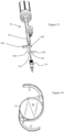
Figure 14 is a representative intraocular lens. - Generally, the present disclosure provides an
IOL injector 10 for presenting anIOL 20 to a surgical site, wherein the IOL injector can be operably controlled with one hand. In certain configurations, the IOLinjector 10 is configured to be single use or disposable. - Referring to
Figures 1-4 and10 , theIOL injector 10 includes aninjector body 30, aguide shaft assembly 50 having aguide shaft 52, apiston 60 and aplunger 80, a compressedgas reservoir 32 and amechanical brake 110 which cooperate for selectively presenting anIOL 20 to a patient. - As used herein, the IOL 20 is an artificial lens used to replace the natural crystalline lens of the eye when the natural lens has cataracts or is otherwise diseased.
IOLs 20 are also sometimes implanted into an eye to correct refractive errors of the eye in which case the natural lens may remain in the eye together with the implanted IOL. The IOL 20 may be placed in either the posterior chamber or anterior chamber of the eye. IOLs 20 come in a variety of structures and materials. Referring toFigure 14 , somecommon IOL 20 styles include the so-called open-looped haptics which include the three-piece type having an optic and twohaptics - It is also understood that the
IOL 20 structure shown and described herein is for discussion purposes only, and that the present disclosure is not to be limited by the particular structure of the IOL. The present system may be easily adapted toIOLs 20 of any structure and type (e.g., IOLs with plate, open or closed loop haptics, anterior chamber IOLs, posterior chamber IOLs, accommodating IOLs (including single and double lens types), etc.). TheIOL 20 has a nominal state in the absence of external forces (other than gravity). That is, the nominal state is the formation the IOL assumes upon the removal of deforming forces. - The
injector body 30 is a generally elongate member sized to retain theguide shaft assembly 50, themechanical brake 110 and at least a portion of the compressedgas reservoir 32, wherein compressed gas is used as the motive force for selectively presenting theIOL 20 to the patient. Theinjector body 30 defines a longitudinal axis (LA) extending along a major length of the injector body wherein movement along the longitudinal axis is movement in a longitudinal direction. - The
injector body 30 can include aleft side housing 31 and aright side housing 33, which define alumen 39 extending along the longitudinal axis. Thelumen 39 can have any of a variety of cross-sectional profiles, wherein circular or oval shapes are typical. Further, thelumen 39 can include a plurality of sections, wherein the sections are parallel but non-collinear. The sections of the lumen can be configured to slideably receive corresponding portions of theguide shaft assembly 50, as set forth below. Thus, certain sections of thelumen 39 can receive different portions of the longitudinally displaceable components of theIOL injector 10, thereby reducing an overall longitudinal dimension of theinjector body 30. A portion of theinjector body 30 may include a configured surface for engaging a portion of a hand of the operator. It is understood that the overall structure of theinjector body 30 may vary from that shown and described herein. It is furthermore understood that the components of theinjector body 30 may be made of any suitable material (e.g., polypropylene) and may be wholly or partly opaque, transparent or translucent to better visualize (i) theIOL 20 within theIOL injector 10 and (ii) the IOL delivery sequence. The material of theinjector body 30 can be selected to provide for the structure being disposable or recyclable, such as in a single use configuration. - In one configuration, the
injector body 30 includes a port or interface for receiving and an IOL support for retaining anIOL 20. The interface and IOL support can be configured to accept and retain a singlefree IOL 20 or can be configured to accept and retain a carry or cartridge such as ashuttle 130, wherein the shuttle as the IOL support retains theIOL 20 for being presented to the patient. Specifically in one configuration, referring toFigures 1-4 , theinjector body 30 includes the interface and ashuttle bay 45 opening into thelumen 39. Theshuttle bay 45 receives or accepts theshuttle 130 for operable engagement with theinjector body 30. Theshuttle bay 45 includes engaging surfaces for engaging theshuttle 130. The engaging surfaces can include alignment surfaces for contacting theshuttle 130 in predetermined locations to provide accurate and reproducible retention of the shuttle in theinjector body 30. Theshuttle 130 thus functions as the IOL support and can be any of a variety of configurations and is not a limiting feature of the present system. Typically, theshuttle 130 includes a shuttle lumen aligned with at least a portion of thelumen 39 of theinjector 10. - In one example, the
injector body 30 further cooperates with aninjector tip 54 which defines an extension of thelumen 39 so as to define a pathway of theIOL 20 to the eye of the patient. Theinjector tip 54 defines a terminal end having a size for insertion into or presentation to the eye, with theIOL 20 correspondingly deformed within the injector tip. However, it is understood, theshuttle 130 can include an integral injector tip or nozzle defining a portion of thelumen 39 for directing theIOL 20 to the patient. - The
injector body 30 can include the compressedgas reservoir 32 for retaining, generating or receiving compressed gas, such as from acompressed gas cartridge 124. As set forth below, the compressedgas reservoir 32 is partly defined by (exposed to) thepiston 60. Depending on the intended operating parameters of theIOL injector 10, thecompressed gas cartridge 124 can be coupled with theinjector body 30 to preclude non-destructive separation, thus providing a feature supporting the single use characteristics of the IOL injector. - The
injector body 30 can define at least a portion of the compressedgas reservoir 32, wherein the compressedgas cartridge 124 can further define a portion of the compressed gas reservoir. It is understood a separate component can be engaged or coupled to theinjector body 30 to define a portion of the compressedgas reservoir 32. The compressedgas reservoir 32 receives compressed gas from the compressedgas cartridge 124 or other source of compressed gas. Thus, it is understood the compressedgas reservoir 32 can be a separate cartridge, an internal volume of theinjector body 30 or a cartridge in conjunction with an internal volume of theinjector body 30 that retains a sufficient volume or mass of compressed gas. - The compressed gas can be any of a variety of gases or mixtures that are biologically compatible with the
IOL 20 and the patient. The compressed gas can be provided by thecartridge 124, a pump, a fan, a compressor or any other mechanism for generating a volume of the compressed gas. In one configuration, the compressed gas is initially retained in the compressedgas cartridge 124. In the configuration employing thecompressed gas cartridge 124, it is contemplated the cartridge is carried by theIOL injector 10 and is selectively pierced to release the compressed gas. - In one configuration, the
injector body 30 includes acap 34 for retaining thecompressed gas cartridge 124 and a piercingpin 36 aligned with a seal of the compressed gas cartridge orcanister 124. The seal of the compressedgas cartridge 124 can be selectively pierced by movement of thecap 34, the piercingpin 36 or a combination of both, wherein the released gas fills the compressedgas reservoir 32 of theinjector body 30 and thus acts on theguide shaft assembly 50 via thepiston 60. - In one configuration, the
guide shaft assembly 50 having theguide shaft 52, thepiston 60 and theplunger 80 are longitudinally overlapping to reduce an overall dimension along the longitudinal axis. That is, rather than coaxially aligning theguide shaft 52, thepiston 60 and theplunger 80 end to end along the longitudinal dimension, a portion of the length of the piston is coextensive with a portion of the guide shaft, thereby reducing the overall length of theguide shaft assembly 50. Theguide shaft 52, thepiston 60 and theplunger 80 are connected such that movement or any one of the components results in a corresponding movement of the remaining components along the longitudinal direction along the longitudinal axis. - The
guide shaft 52 of theguide shaft assembly 50 can include or be coupled to thepiston 60 and theplunger 80. Theguide shaft 52, thepiston 60 and theplunger 80 can thus be integral or individually formed components that are subsequently joined. Further, theguide shaft assembly 50 can be of various configurations to provide the functionality of thepiston 60 and theplunger 80. For purposes of description, all such configurations are referred to as theguide shaft assembly 50. Thus, as thepiston 60 moves along the longitudinal direction, both theguide shaft 52 and theplunger 80 correspondingly move along the longitudinal direction. - The
piston 60, and hence guideshaft assembly 50, is slideably connected to theinjector body 30 and defines a portion of the compressedgas reservoir 32. As set forth below, thepiston 60 is connected to theguide shaft 52 and thus coupled in turn to themechanical brake 110. Thepiston 60 is movable between a fixed, retracted or braked, first position and an actuated or extended second position. Thepiston 60 includes aseal 62 for forming a sealed interface with theinjector body 30. One section of thelumen 39 of theinjector body 30 includes aninner surface 42 forming a sealed interface with thepiston 60 as the piston moves in response to exposure to the compressed gas. - Referring to
Figures 7 and 8 , theplunger 80 includes aplunger shaft 82 and aplunger tip 84 configured for engaging theIOL 20 and specifically the optic 26 at the periphery of the optic as the plunger is advanced along the shuttle lumen. It is understood that other plunger tip designs may be used with the present system. It is furthermore preferred that theplunger shaft 82 is rotationally fixed within thelumen 39 to prevent unexpected rotation of the plunger shaft (and thus the plunger tip 84) relative to the lumen. Theplunger shaft 82 may be rotationally fixed by forming the proximal shaft length and lumen non-circular in cross-section or by including rotational fixing elements on the lumen inner wall and plunger shaft (e.g., longitudinal flange on the plunger having a sliding fit within a longitudinally extending groove provided on the lumen inner wall). - The
plunger shaft 82 is connected to or driven by theguide shaft 52 such that movement of the guide shaft along the longitudinal axis correspondingly moves theplunger 80 along the longitudinal axis. Thus, in one configuration, thepiston 60, theguide shaft 52 and theplunger 80 move as a single unit. Although thepiston 60, theguide shaft 52 and theplunger 80 are shown as separate components, it is contemplated these components can be integrally formed or connected to form a single piece. - The
guide shaft 52, thepiston 60 and theplunger 80 are moveable between the retracted position and the extended position, wherein movement from the retracted position to the extended or actuated position presents theIOL 20 to the patient. Each of theguide shaft 52, thepiston 60 and theplunger 80 are moveable along a corresponding section of thelumen 39, and depending on the construction of the guide shaft, the piston and the plunger can be collinear or parallel. - As seen in
Figures 1-4 , and11-13 , theIOL injector 10 can include afirst stop 180 and asecond stop 190. Thefirst stop 180 and thesecond stop 190 selectively block movement of theguide shaft assembly 50 along the longitudinal axis from the retracted position toward the extended position. Each of thefirst stop 180 and thesecond stop 190 are moveable between a blocking position, blocking further movement of theguide shaft assembly 50 and a passing position, permitting further movement of the guide shaft assembly. Thefirst stop 180 and thesecond stop 190 can be used to control movement of theguide shaft assembly 50 along the longitudinal axis from the retracted position to a ready position, an actuated position and a venting position. - In one configuration, the first and the second stops 180, 190 are moveable from the blocking position to the passing position by sliding transverse to the longitudinal axis. However, it is understood the
first stop 180 and thesecond stop 190 can be any of a variety of configurations. Referring to the Figures, thefirst stop 180 and thesecond stop 190 include a blockingportion recess guide shaft assembly 50 to correspondingly block or permit movement of the assembly in the longitudinal direction. - In one configuration, the
first stop 180 limits movement of theguide shaft assembly 50 along the longitudinal axis at a point where theIOL 20 has been folded as it moves at least partly from theshuttle 130, however the IOL remains within theIOL injector 54. Thus, a surgical technician can prep theIOL injector 10 for a surgeon by moving theguide shaft assembly 50 along the longitudinal axis from the retracted position to contact thefirst stop 180, thereby at least partly forming theIOL 20 into an injection configuration while reducing the risk of spontaneous (unintended) ejection of the IOL from the IOL injector. TheIOL injector 10 is then provided to the surgeon who can move the first stop to the passing position and can control themechanical brake 110 to move the guide shaft assembly from the position of the first stop to deliver theIOL 20 to the patient. It is understood thefirst stop 180 and theguide shaft assembly 50 can be configured such that upon contact with the first stop, the guide shaft assembly (and hence plunger 80) are at any of a variety ofIOL 20 preparation positions, such as but not limited to prior to contact with the IOL, contacting the IOL, partially folding the IOL or fully disposing the IOL in an injection configuration. - Actuation of the first stop 180 (moving to the first stop to the passing position) followed by manipulation of the
mechanical brake 110, allows continued movement of theguide shaft assembly 50 from the position of the first stop along the longitudinal axis until the guide shaft assembly contacts thesecond stop 190. - The
second stop 190 can be located to limit movement of theguide shaft assembly 50 along the longitudinal axis at a point where theIOL 20 has been passed from theIOL injector 10 and a portion of theplunger tip 84 has passed from theIOL injector 10. Thus, theIOL injector 10 has fulfilled the function of presenting theIOL 20 to the patient and providing theplunger tip 84 for manipulation of the IOL during the insertion process. - As seen in
Figures 2-4 and13 , thefirst stop 180 is initially disposed in the blocking position and can include a bias member acting to urge thefirst stop 180 to the blocking position or resist movement of thefirst stop 180 from the blocking position. The bias member can be any of a variety of constructions, such as projecting tab that is biased to urge thefirst stop 180 to the blocking position. - As seen in
Figures 1 ,3 and13 , thesecond stop 190 is also initially disposed in the blocking position. In one configuration, thesecond stop 190 is configured to at least substantially preclude actuation by use of just the hands of the operator. It is contemplated that a separate tool can be used to move thesecond stop 190 to the passing position, thereby allowing the venting of any remaining compressed gas. - That is, the
compressed gas cartridge 124 is typically sized to retain an excess of compressed gas to ensure sufficient motive force for presenting theIOL 20. Thus, upon theguide shaft assembly 50 contacting thesecond stop 190, in this state, thecompressed gas cartridge 124 typically retains a volume of compressed gas. - To reduce disposal concerns of the compressed
gas cartridge 124 still retaining a mass of compressed gas, thesecond stop 190 can be moved to allow movement of theguide shaft assembly 50 past thesecond stop 190. This continued movement of theguide shaft assembly 50 allows theseal 62 to pass a vent port in theinjector body 10 thereby allowing any higher than ambient pressure compressed gas to vent. - Movement of the
guide shaft assembly 50 along the longitudinal axis from the retracted position towards the extended position causes theplunger tip 84 to contact theIOL 20, wherein the IOL is folded as it moves at least partly from theshuttle 130, however the IOL remains within the IOL injector. - Generally, the compressed gas imparts a force on the guide shaft assembly 50 (via the piston 60) to translate the
guide shaft 52 along the longitudinal direction thereby moving the plunger 80 (and upon contact, the IOL 20) toward to the patient. Themechanical brake 110 initially precludes movement of theguide shaft 52 until operator input changes the mechanical resistance to the longitudinal translation. - The
mechanical brake 110 selectively resists translation of theguide shaft 52, theplunger 80 and thepiston 60 along the longitudinal axis. Themechanical brake 110 can have a variety of configurations which allow the operator to selectively vary the resistance to the longitudinal translation and hence speed of the passage of theIOL 20 through and from theinjector 10. - In one configuration, the
mechanical brake 110 includes arack 70 with a plurality ofteeth 72 on theguide shaft 52, wherein the teeth engage arotatable gear 100, such as a pinion gear, and wherein rotation of the gear is mechanically retarded until variably changed by the operator. Although theguide shaft 52 and therack 70 are shown as integral, it is understood the elements could be formed separately and subsequently joined to be a single piece construction. - In this one configuration, the
mechanical brake 110 can include avariable friction member 90 acting on thegear 100 via abrake drum 112. Thegear 100 and thebrake drum 112 are coupled together and thus rotate together about a common axis relative to theinjector body 30. - In this configuration, the
mechanical brake 110 operates by limiting rotation of thegear 100 that is engaged with the guide shaft 52 (by means of the rack 70). Themechanical brake 110 can include the variable friction member, such as thewound brake coil 90 disposed about a portion of thebrake drum 112, wherein the brake coil has a default configuration gripping the brake drum. That is, absent any operator input, thebrake coil 90 engages or grips thebrake drum 112 to preclude rotation of thegear 100 in response to exposure of thepiston 60 to the compressed gas in the compressedgas chamber 32. As thebrake coil 90 grips thebrake drum 112 and is connected to theinjector body 30, the brake drum is precluded from rotating. Thebrake coil 90 and thebrake drum 112 are configured to preclude rotation of the brake drum (and hence rotation of thegear 100 and longitudinal translation of the guide shaft assembly 50) upon exposure of thepiston 60 to the compressed gas in the compressedgas reservoir 32. - Referring to
Figures 3, 4 ,9 ,11 and 12 , the variable mechanical resistance can be accomplished by adjustment of thebrake coil 90 about thebrake drum 112. The adjustment is provided by arelease lever 160 acting onbrake slide 166, which is turn is connected to thebrake coil 90. Therelease lever 160 is rotatable about a rotation axis through a range of motion between a maximum braking position and a minimum braking position. Therelease lever 160 is coupled to thebrake slide 166 by alink 164 pivotally connected at each end between the release lever and thebrake slide 166. By virtue of the rotation of therelease lever 160 and the pivoting connection of thelink 164 between the lever and thebrake slide 166, the amount of travel of the brake slide (and hence amount of change in the force applied by the brake) decreases for a given amount of rotation of the release lever as the release lever operates near the minimum braking position. That is, not only does the rotation of therelease lever 160 allow continuous adjustment of the braking force (and hence continuous adjustment of the movement of the guide shaft assembly 50), but the change in braking force for a given movement of the release lever decreases as the release lever operates near the minimum braking force range. - The
brake slide 166 extends between therelease lever 160 and thebrake coil 90. Thebrake slide 166 includes acatch 169 for engaging a portion of thebrake coil 90. In one configuration, an end of thebrake coil 90 projects from thebrake drum 112 and engages thecatch 169, wherein the brake coil exerts a bias against the catch and hence thebrake slide 166. This bias on thebrake slide 166 urges the brake slide to pivot thelink 164 to rotate therelease lever 160 to the maximum braking force position, or the stop position. Operator imparted rotation of therelease lever 160 about the pivot 163 causes thelink 164 to move thebrake slide 166 along the longitudinal axis in the longitudinal direction. As thebrake slide 166 is connected to thebrake coil 90, the longitudinal translation of thebrake slide 166 tends to loosen the brake coil relative to thebrake drum 112, thereby allowing rotation of the brake drum and hence thegear 100. While the rotation of therelease lever 160 and relaxing of thebrake coil 90 are shown as infinitely adjustable (not stepped), it is contemplated that movement of either or both could be stepped or incremented, such as by teeth or steps on one of the surfaces. - As the
gear 100 engages theteeth 72 of the rack 70 (and the rack is coupled to or part of the guide shaft 52), permitting rotation of thebrake drum 112 andgear 100 allows corresponding longitudinal translation of the guide shaft. Themechanical brake 110 is also connected to theinjector body 30 and movable between (i) an engaged maximum braking position, precluding rotation of thegear 100 and thus precluding longitudinal movement of therack 70 and hence the guide shaft 52 (and the plunger 80) relative to the injector body and (ii) a retracted position permitting rotation of the gear and thus corresponding longitudinal movement of the rack, the guide shaft and the plunger relative to the injector body. By varying the friction of thebrake coil 90 on thebrake drum 112, themechanical brake 110 can apply a variable resistance to rotation of thegear 100 and hence longitudinal movement of theguide shaft assembly 50. Thus, the velocity of longitudinal translation of theguide shaft 52 can be operator controlled by themechanical brake 110. - Partial unwinding (or loosening) of the
brake coil 90 on thebrake drum 112 reduces the resistance to rotation of thegear 100 and hence reduces the resistance to longitudinal translation of theguide shaft assembly 50. Thus, loosening thebrake coil 90 about thebrake drum 112, the operator can selectively vary the engagement of themechanical brake 110 to control the translational movement of the guide shaft assembly 50 (and hence plunger 80) along the longitudinal direction. - In one configuration, a
control knob 116 can be selectively engaged with thebrake drum 112 to impart rotation of thegear 100 to move theguide shaft assembly 50 in the longitudinal direction to retract theplunger 80. Thecontrol knob 116 is rotatable to be able to move the rack 70 (via rotation of the gear 100), and hence theguide shaft 52 and theplunger 80, toward the first retracted position, away from the patient. Thus, the operator can reverse the direction of movement of theguide shaft 52 and theplunger 80, as necessary. - Although the
mechanical brake 110 is shown as thebrake coil 90 and thebrake drum 112 with thegear 100 coupled to the brake drum, it is understood the mechanical brake can be any of a variety of mechanical engagements that selectively permit and preclude movement of theguide shaft assembly 50 along the longitudinal direction in response to the exposure of thepiston 60 to the compressed gas. - Thus, the
mechanical brake 110 can include, for example, a pressure pad or wheel that is biased to engage theguide shaft assembly 50, wherein operator input acts against (or changes) the bias of the mechanical brake to reduce engagement with theguide shaft 52, such that the force on thepiston 60 from the compressed gas overcomes the resistance to motion and theplunger 80 is allowed to move in a controlled translation. Alternatively, themechanical brake 110 can include, for example, an endless belt that engages theguide shaft assembly 50 and a roller or idler, wherein motion of the belt is selectively restricted, such as by restricting rotation of the roller or compression upon the belt. - As seen in
Figures 3 ,9 ,10 and11 , theinjector 10 can include alimiter 140 for limiting the velocity or establishing a maximum velocity of theguide shaft assembly 50 along the longitudinal axis. In one configuration, theinjector body 30 includes at least one, and as seen in the figures, a plurality ofcavities 143, wherein each cavity is sized to receive a corresponding plate ordisk 146. Theplates 146 are disposed about a portion of thebrake drum 112 and are couple to the brake drum so as to rotate with the brake drum and hence thegear 100. A thick grease or paste can be disposed in thecavity 143, wherein the grease is selected to impart sufficient friction on theplates 146 to limit rotational velocity of the plates, and hence thegear 100 and thus theguide shaft assembly 50. Thus, even if themechanical brake 110 is released to its fullest extent, a maximum velocity of theplunger 80 is set by thelimiter 140. TheIOL injector 10 provides for single hand operation as the injector body is sized to fit into a hand. Further, as themechanical brake 110 is selectively variable, the operator, by using the hand that is retaining theIOL injector 10 can manipulate therelease lever 160 to control presentation of theIOL 20 to the patient, to provide single hand operation. - In select configurations, the
IOL injector 10 is shipped and stored in a storage position, wherein the compressed gas cartridge is sealed and has not been punctured. Thus, theguide shaft assembly 50 is not exposed to the compressed gas. - The
shuttle 130 carrying the retainedIOL 20 is engaged with theinjector body 30. To dispense theIOL 20 from theinjector body 30, the compressedgas reservoir 32 is filled with compressed gas 120, such as by selectively piercing thecompressed gas cartridge 124. Thepiston 60 is thus exposed to the compressed gas 120 which exerts a force on the piston, urging the piston toward the extended position. - The
mechanical brake 110 defaults to an engaged configuration as thebrake coil 90 and precludes rotation of thebrake drum 112 and hence precludes rotation of thegear 100. As thegear 100 is engaged with theguide shaft assembly 50 via the rack 70 (and theguide shaft 52 is connected to the piston 60) there is no movement of the guide shaft assembly. Thus, there is initially no movement of theguide shaft assembly 50 and hence no movement of theplunger 80 upon thepiston 60 being exposed to the compressed gas. - Once the operator desires to initiate the procedure to introduce the
IOL 20 to the patient, themechanical brake 110 is at least partially released (by depressing therelease lever 160 and relaxing thebrake coil 90 about the brake drum 112), allowing rotation of thegear 100, which allows therack 70 and theguide shaft 52 to translate longitudinally in response to exposure of the compressed gas 120 with thepiston 60. Specifically, therelease lever 160 is rotated thereby sliding thebrake slide 166 to loosen the brake coil and allow the brake drum to begin to rotate, thereby allowing thepiston 60 to move in response to the compressed gas in the compressedgas reservoir 32. - As the
piston 60 moves, theguide shaft 52, therack 70 and theplunger 80 also move relative to theinjector body 30 in the longitudinal direction along the longitudinal axis. The movement of therack 70 and hence guideshaft assembly 50 corresponds to rotation of thegear 100. This movement causes theplunger 80 to contact theIOL 20 and transition the IOL from the shuttle 130 (or storage position) into theinjector tip 54. - At this point, the
guide shaft assembly 50 contacts the blockingportion 182 of thefirst stop 180 and further translation of theplunger 80 is stopped. - While it has been described as the compressed gas moving the
guide shaft assembly 50 to contact thefirst stop 180, it is contemplated that the operator can manually move theguide shaft assembly 50 from the retracted or storage position to contact thefirst stop 180. With theguide shaft assembly 50 engaged with thefirst stop 180, and further movement along the longitudinal axis precluded, thecompressed gas cartridge 124 can then opened/punctured so that the compressed gas acts on thepiston 60. In this, position of theguide shaft assembly 50 both themechanical brake 110 and thefirst stop 180 prohibit further translation of the guide shaft assembly (and hence plunger 80) relative to the injector body. - The
first stop 180 can then be disposed to the passing position aligning the passingrecess 184 with theguide shaft assembly 50, and themechanical brake 110 continues to preclude movement of the guide shaft assembly 50 (and hence plunger 80) relative to theinjector body 30. Therelease lever 160 is then controlled by the operator to selectively permit movement of theguide shaft assembly 50 including theplunger 80 and theIOL 20. - Upon the operator releasing or reducing pressure on the
release lever 160, thebrake coil 90 increases engagement with thebrake drum 112, thereby inhibiting rotation of the brake drum. The inhibited rotation of thebrake drum 112 inhibits longitudinal movement of theguide shaft 52 and theplunger 80. By varying the amount of engagement of thebrake coil 90 and the brake drum 112 (by varying the movement of the release lever 160), the operator can vary the speed ofplunger 80 translating along the longitudinal direction. - Since the
mechanical brake 110 defaults to a status or position that precludes longitudinal translation of theplunger 80, only upon operator input of at least partly releasing themechanical brake 110, is theguide shaft 52 allowed to translate along the longitudinal direction. - Thus, the termination of operator input at any point causes the mechanical brake 110 (via the
brake coil 90 to stop rotation of the brake drum 112) to halt movement of therack 70 and hence theIOL 20 towards the patient. - As set forth above, the
guide shaft assembly 50 can then move toward the extended position until the guide shaft assembly contacts the blockingportion 192 of thesecond stop 190. In this position, a portion of theplunger tip 84 projects from theinjector tip 54, thereby allowing the operator to use the injector tip as necessary to orient or locate theIOL 20 relative to the patient. - If the operator desires to reverse the
plunger 80, thecontrol knob 116 can be engaged with thebrake drum 112 and actuated to retract therack 70, and henceplunger 80. - Upon completion of the procedure, the
second stop 190 can be moved to the passing position aligning the passingrecess 194 with theguide shaft assembly 50 thereby allowing the compressed gas to further move thepiston 60 and expose the vent port to the compressedgas reservoir 32, thereby venting any remaining compressed gas from the compressedgas cartridge 124 and theIOL injector 10. - It will be apparent to those skilled in the art that the invention may be implemented in various ways, and that modifications and improvements will readily occur to such persons. Thus, the embodiments are not intended to be limiting and presented by way of example only. The scope of the invention is defined by the appended claims.
Claims (15)
- An intraocular lens (IOL) injector (10) comprising:(a) a compressed gas reservoir (32) for retaining a compressed gas;(b) a guide shaft assembly (50) exposed to the compressed gas reservoir (32), the guide shaft assembly (50) being moveable along a longitudinal direction from a retracted position to an extended position, the guide shaft assembly (50) including a guide shaft (52), a piston (60), and a plunger (80), wherein a portion of the length of the piston (60) is coextensive with a portion of the length of the guide shaft (52); and(c) a mechanical brake (110) operably coupled to the guide shaft assembly (50), the mechanical brake (110) configured to exert on the guide shaft assembly (50), in response to an operator actuation, a variable resistance to the longitudinal movement of the guide shaft assembly (50), the mechanical brake (110) having a default engagement with the guide shaft assembly (50) to preclude movement of the guide shaft assembly (50) in response to exposure of the guide shaft assembly (50) to compressed gas in the compressed gas reservoir (32).
- The IOL injector (10) of Claim 1, wherein the piston (60) is located to be exposed to the compressed gas reservoir (32), and/or wherein the guide shaft assembly (50) includes a plunger tip (84).
- The IOL injector (10) of Claim 1, wherein the mechanical brake (110) includes a rotatable brake drum (112) and a gear (100) connected to the brake drum (112).
- The IOL injector (10) of Claim 3, wherein the mechanical brake (110) includes a resilient brake coil (90) wrapped about the rotatable brake drum (112).
- The IOL injector (10) of Claim 1, wherein the compressed gas reservoir (32) retains a constant mass of the compressed gas.
- The IOL injector (10) of Claim 1, wherein a mass of the compressed gas is sufficient to fully translate the guide shaft assembly (50) from the retracted position to the extended position.
- The IOL injector (10) of Claim 1, further comprising a limiter (140) operably coupled to the guide shaft assembly (50) for limiting a velocity of the guide shaft assembly (50) in response to exposure to the compressed gas.
- The IOL injector (10) of Claim 1, wherein the mechanical brake (110) is configured to return to the
default engagement with the guide shaft assembly (50) upon cessation of operator actuation. - The IOL injector (10) of Claim 1, wherein the guide shaft assembly (50) is configured to move along
the longitudinal direction from the retracted position to the extended position in response to the compressed gas in the compressed gas reservoir (32). - The IOL injector (10) of Claim 1, further comprising a first stop (180) located to permit movement of the guide shaft assembly (50) from the retracted position toward the extended position and preclude movement of the guide shaft assembly (50) to the extended position.
- The intraocular lens (IOL) injector (10) of Claim 1, comprising:(a) an IOL support configured to receive and retain an IOL (20) for presentation to an eye of a patient; and(b) a moveable control surface connected to the mechanical brake (110) to move the mechanical brake (110) from the default position to apply a variable mechanical resistance to movement of the guide shaft assembly (50) from the retracted position to the extended position in response to exposure to the compressed gas in the compressed gas reservoir (32),
wherein the guide shaft assembly (50) is translatable from the retracted position spaced from the IOL (20) to the extended position contacting and displacing the IOL (20) from the IOL support for insertion into an eye of a patient. - The IOL injector (10) of Claim 11, wherein the moveable control surface is a coil (90).
- A method for assembling the IOL injector (10) of any one of claims 1 to 12, comprising:(a) disposing the guide shaft assembly (50) within the injector body (30) of the intraocular lens (IOL) injector (10); and(b) engaging the mechanical brake (110) operably coupled to the guide shaft assembly (50) to exert an operator actuated variable resistance to the longitudinal movement of the guide shaft assembly (50), the brake (110) having a default engagement with the guide shaft assembly (50) to preclude longitudinal movement of the guide shaft (52) in response to exposure of the guide shaft assembly (50) to compressed gas in the compressed gas reservoir (32).
- The method of claim 13, further comprising operably connecting the piston (60) to the guide shaft assembly (50), and/orfurther comprising coupling a limiter (140) to the guide shaft assembly (50) for limiting a velocity of the guide shaft assembly (50) in response to exposure to the compressed gas, and/orfurther comprising locating a stop (180, 190) to preclude movement of the guide shaft assembly (50) from towards the extended position.
- The method of claim 13, wherein engaging the mechanical brake (110) includes contacting the guide shaft assembly (50) in response to the user actuation.
Applications Claiming Priority (2)
| Application Number | Priority Date | Filing Date | Title |
|---|---|---|---|
| US201862649353P | 2018-03-28 | 2018-03-28 | |
| PCT/US2019/024053 WO2019191080A1 (en) | 2018-03-28 | 2019-03-26 | Injector assembly employing compressed gas and a mechanical brake for presenting an intraocular lens to a patient |
Publications (2)
| Publication Number | Publication Date |
|---|---|
| EP3773333A1 EP3773333A1 (en) | 2021-02-17 |
| EP3773333B1 true EP3773333B1 (en) | 2023-10-18 |
Family
ID=66429456
Family Applications (1)
| Application Number | Title | Priority Date | Filing Date |
|---|---|---|---|
| EP19722226.8A Active EP3773333B1 (en) | 2018-03-28 | 2019-03-26 | Injector assembly employing compressed gas and a mechanical brake for presenting an intraocular lens to a patient |
Country Status (8)
| Country | Link |
|---|---|
| US (1) | US11701222B2 (en) |
| EP (1) | EP3773333B1 (en) |
| JP (1) | JP7405761B2 (en) |
| KR (1) | KR102718132B1 (en) |
| CN (1) | CN111918622B (en) |
| CA (1) | CA3094349A1 (en) |
| ES (1) | ES2962595T3 (en) |
| WO (1) | WO2019191080A1 (en) |
Families Citing this family (4)
| Publication number | Priority date | Publication date | Assignee | Title |
|---|---|---|---|---|
| US11867359B2 (en) * | 2016-03-08 | 2024-01-09 | Picocyl, Llc | Gas canisters and methods for making them |
| FR3080289B1 (en) * | 2018-04-18 | 2021-10-29 | Nemera La Verpilliere | IMPLANT INJECTION DEVICE WITH FRICTION RETAINING MEANS |
| DE102020115482A1 (en) | 2020-06-10 | 2021-12-16 | Carl Zeiss Meditec Ag | Injector assembly for inserting an intraocular lens and injector |
| WO2026084707A1 (en) * | 2024-10-16 | 2026-04-23 | Carl Zeiss Meditec Ag | Conveyor unit for intraocular lens injector device and intraocular lens injector device with such conveyor unit |
Family Cites Families (30)
| Publication number | Priority date | Publication date | Assignee | Title |
|---|---|---|---|---|
| JPS6188618A (en) | 1984-10-05 | 1986-05-06 | Hitachi Ltd | pulse generator |
| AU623934B2 (en) | 1988-10-07 | 1992-05-28 | Ioptex Research Inc | Intraocular lens insertion instrument |
| US6503275B1 (en) | 1996-11-15 | 2003-01-07 | Medevec Licensing, B.V. | Ophthalmic lens insertion instrument and package |
| US6010510A (en) * | 1998-06-02 | 2000-01-04 | Alcon Laboratories, Inc. | Plunger |
| EP1428484B1 (en) * | 2002-12-09 | 2008-04-30 | Anton Meyer & Co. AG | Plunger nedle for iol injector |
| US20050283162A1 (en) | 2004-06-22 | 2005-12-22 | Stratas Byron A | Intraocular lens inserter |
| WO2006059183A1 (en) | 2004-11-30 | 2006-06-08 | Bausch & Lomb Incorporated | Two stage plunger for intraocular lens injector |
| US20080004610A1 (en) | 2006-06-30 | 2008-01-03 | David Miller | System for calculating IOL power |
| US20090018548A1 (en) | 2007-07-13 | 2009-01-15 | Charles Steven T | Pneumatically-Powered Intraocular Lens Injection Device with Removable Cartridge |
| US8439973B2 (en) | 2008-05-20 | 2013-05-14 | Amo Regional Holdings | Plungers for intraocular lens injectors |
| JP5416379B2 (en) | 2008-09-04 | 2014-02-12 | Hoya株式会社 | Intraocular lens insertion device |
| US8801780B2 (en) | 2008-10-13 | 2014-08-12 | Alcon Research, Ltd. | Plunger tip coupling device for intraocular lens injector |
| US8308736B2 (en) | 2008-10-13 | 2012-11-13 | Alcon Research, Ltd. | Automated intraocular lens injector device |
| US9125737B2 (en) * | 2008-12-18 | 2015-09-08 | Alcon Research, Ltd. | Constant force intraocular lens injector |
| AU2011242540C1 (en) | 2010-04-23 | 2018-09-27 | Johnson & Johnson Surgical Vision, Inc. | Insertion mode phacoemulsification employing powered IOL delivery |
| US8579969B2 (en) | 2010-07-25 | 2013-11-12 | Alcon Research, Ltd. | Dual mode automated intraocular lens injector device |
| US8400808B2 (en) | 2010-12-16 | 2013-03-19 | Micron Technology, Inc. | Phase interpolators and push-pull buffers |
| US9421129B2 (en) | 2012-04-02 | 2016-08-23 | Ocuject, Llc | Intraocular delivery devices and methods therefor |
| PT2854708T (en) | 2012-06-04 | 2017-01-17 | Alcon Pharmaceuticals Ltd | Intraocular lens inserter and method for discharging an intraocular lens from a cartridge |
| US9155615B2 (en) | 2012-11-09 | 2015-10-13 | Bausch & Lomb Incorporated | Hingeless cartridge for use with an intraocular lens injector providing haptic control |
| EP2928423B1 (en) * | 2012-12-05 | 2020-07-15 | Hoya Corporation | Ocular implant insertion apparatus |
| WO2014129977A1 (en) | 2013-02-21 | 2014-08-28 | Singapore Health Services Pte Ltd | Device for single handled injection of an intraocular lens |
| EP2964151B1 (en) | 2013-03-05 | 2019-07-31 | Johnson & Johnson Surgical Vision, Inc. | Automated preloaded intraocular lens injector |
| EP3068475B1 (en) * | 2013-11-13 | 2021-12-15 | F. Hoffmann-La Roche AG | Assisted manual injector devices and methods |
| WO2015154049A1 (en) | 2014-04-04 | 2015-10-08 | Altaviz, Llc | Intraocular lens inserter |
| CN106572904B (en) | 2014-07-15 | 2019-06-18 | 爱尔康制药有限公司 | Intraocular lens inserter with temperature compensation |
| US10172706B2 (en) * | 2015-10-31 | 2019-01-08 | Novartis Ag | Intraocular lens inserter |
| US10343545B2 (en) * | 2016-01-15 | 2019-07-09 | Trumpet Holdings, Inc. | Systems and methods for separating batteries |
| US10405972B2 (en) * | 2016-06-23 | 2019-09-10 | Novartis Ag | Systems and methods for intraocular lens deployment |
| US10226328B2 (en) * | 2016-08-17 | 2019-03-12 | Novartis Ag | Systems and methods for deployment damping in intraocular lens deployment |
-
2019
- 2019-03-26 JP JP2020549571A patent/JP7405761B2/en active Active
- 2019-03-26 KR KR1020207030635A patent/KR102718132B1/en active Active
- 2019-03-26 ES ES19722226T patent/ES2962595T3/en active Active
- 2019-03-26 EP EP19722226.8A patent/EP3773333B1/en active Active
- 2019-03-26 CA CA3094349A patent/CA3094349A1/en active Pending
- 2019-03-26 WO PCT/US2019/024053 patent/WO2019191080A1/en not_active Ceased
- 2019-03-26 US US16/364,968 patent/US11701222B2/en active Active
- 2019-03-26 CN CN201980022999.0A patent/CN111918622B/en active Active
Also Published As
| Publication number | Publication date |
|---|---|
| US11701222B2 (en) | 2023-07-18 |
| CN111918622A (en) | 2020-11-10 |
| CN111918622B (en) | 2024-12-06 |
| CA3094349A1 (en) | 2019-10-03 |
| KR102718132B1 (en) | 2024-10-17 |
| JP7405761B2 (en) | 2023-12-26 |
| ES2962595T3 (en) | 2024-03-20 |
| EP3773333A1 (en) | 2021-02-17 |
| KR20200138299A (en) | 2020-12-09 |
| US20190298512A1 (en) | 2019-10-03 |
| WO2019191080A1 (en) | 2019-10-03 |
| JP2021518181A (en) | 2021-08-02 |
Similar Documents
| Publication | Publication Date | Title |
|---|---|---|
| US7988701B2 (en) | Preloaded IOL injector | |
| US7947049B2 (en) | IOL injector | |
| US8273122B2 (en) | Pre-loaded IOL insertion system | |
| US11701222B2 (en) | Injector assembly employing compressed gas and a mechanical brake for presenting an intraocular lens to a patient | |
| US7422604B2 (en) | Preloaded IOL injector | |
| US20050149057A1 (en) | IOL inserter plunger and body interface | |
| CN112384172B (en) | Intraocular lens injector | |
| JP2008521535A (en) | Two-stage plunger for intraocular lens insertion device | |
| WO2014089250A1 (en) | Ocular implant insertion apparatus and methods | |
| US20260069404A1 (en) | Folding device for intraocular lens injector | |
| US20050149056A1 (en) | IOL injector device and method | |
| EP3372197A1 (en) | Intraocular lens injector and method for operating an intraocular lens injector | |
| EP3860513B1 (en) | Iol folding device |
Legal Events
| Date | Code | Title | Description |
|---|---|---|---|
| STAA | Information on the status of an ep patent application or granted ep patent |
Free format text: STATUS: UNKNOWN |
|
| STAA | Information on the status of an ep patent application or granted ep patent |
Free format text: STATUS: THE INTERNATIONAL PUBLICATION HAS BEEN MADE |
|
| PUAI | Public reference made under article 153(3) epc to a published international application that has entered the european phase |
Free format text: ORIGINAL CODE: 0009012 |
|
| STAA | Information on the status of an ep patent application or granted ep patent |
Free format text: STATUS: REQUEST FOR EXAMINATION WAS MADE |
|
| 17P | Request for examination filed |
Effective date: 20201019 |
|
| AK | Designated contracting states |
Kind code of ref document: A1 Designated state(s): AL AT BE BG CH CY CZ DE DK EE ES FI FR GB GR HR HU IE IS IT LI LT LU LV MC MK MT NL NO PL PT RO RS SE SI SK SM TR |
|
| AX | Request for extension of the european patent |
Extension state: BA ME |
|
| DAV | Request for validation of the european patent (deleted) | ||
| DAX | Request for extension of the european patent (deleted) | ||
| STAA | Information on the status of an ep patent application or granted ep patent |
Free format text: STATUS: EXAMINATION IS IN PROGRESS |
|
| 17Q | First examination report despatched |
Effective date: 20220613 |
|
| GRAP | Despatch of communication of intention to grant a patent |
Free format text: ORIGINAL CODE: EPIDOSNIGR1 |
|
| STAA | Information on the status of an ep patent application or granted ep patent |
Free format text: STATUS: GRANT OF PATENT IS INTENDED |
|
| INTG | Intention to grant announced |
Effective date: 20230419 |
|
| GRAS | Grant fee paid |
Free format text: ORIGINAL CODE: EPIDOSNIGR3 |
|
| GRAA | (expected) grant |
Free format text: ORIGINAL CODE: 0009210 |
|
| STAA | Information on the status of an ep patent application or granted ep patent |
Free format text: STATUS: THE PATENT HAS BEEN GRANTED |
|
| P01 | Opt-out of the competence of the unified patent court (upc) registered |
Effective date: 20230828 |
|
| P02 | Opt-out of the competence of the unified patent court (upc) changed |
Effective date: 20230828 |
|
| AK | Designated contracting states |
Kind code of ref document: B1 Designated state(s): AL AT BE BG CH CY CZ DE DK EE ES FI FR GB GR HR HU IE IS IT LI LT LU LV MC MK MT NL NO PL PT RO RS SE SI SK SM TR |
|
| RAP1 | Party data changed (applicant data changed or rights of an application transferred) |
Owner name: BAUSCH + LOMB IRELAND LIMITED |
|
| REG | Reference to a national code |
Ref country code: GB Ref legal event code: FG4D |
|
| REG | Reference to a national code |
Ref country code: CH Ref legal event code: EP |
|
| REG | Reference to a national code |
Ref country code: IE Ref legal event code: FG4D |
|
| REG | Reference to a national code |
Ref country code: DE Ref legal event code: R096 Ref document number: 602019039565 Country of ref document: DE |
|
| REG | Reference to a national code |
Ref country code: LT Ref legal event code: MG9D |
|
| REG | Reference to a national code |
Ref country code: NL Ref legal event code: MP Effective date: 20231018 |
|
| REG | Reference to a national code |
Ref country code: AT Ref legal event code: MK05 Ref document number: 1621773 Country of ref document: AT Kind code of ref document: T Effective date: 20231018 |
|
| REG | Reference to a national code |
Ref country code: ES Ref legal event code: FG2A Ref document number: 2962595 Country of ref document: ES Kind code of ref document: T3 Effective date: 20240320 |
|
| PG25 | Lapsed in a contracting state [announced via postgrant information from national office to epo] |
Ref country code: NL Free format text: LAPSE BECAUSE OF FAILURE TO SUBMIT A TRANSLATION OF THE DESCRIPTION OR TO PAY THE FEE WITHIN THE PRESCRIBED TIME-LIMIT Effective date: 20231018 |
|
| PG25 | Lapsed in a contracting state [announced via postgrant information from national office to epo] |
Ref country code: GR Free format text: LAPSE BECAUSE OF FAILURE TO SUBMIT A TRANSLATION OF THE DESCRIPTION OR TO PAY THE FEE WITHIN THE PRESCRIBED TIME-LIMIT Effective date: 20240119 |
|
| PG25 | Lapsed in a contracting state [announced via postgrant information from national office to epo] |
Ref country code: IS Free format text: LAPSE BECAUSE OF FAILURE TO SUBMIT A TRANSLATION OF THE DESCRIPTION OR TO PAY THE FEE WITHIN THE PRESCRIBED TIME-LIMIT Effective date: 20240218 |
|
| PG25 | Lapsed in a contracting state [announced via postgrant information from national office to epo] |
Ref country code: LT Free format text: LAPSE BECAUSE OF FAILURE TO SUBMIT A TRANSLATION OF THE DESCRIPTION OR TO PAY THE FEE WITHIN THE PRESCRIBED TIME-LIMIT Effective date: 20231018 |
|
| PG25 | Lapsed in a contracting state [announced via postgrant information from national office to epo] |
Ref country code: AT Free format text: LAPSE BECAUSE OF FAILURE TO SUBMIT A TRANSLATION OF THE DESCRIPTION OR TO PAY THE FEE WITHIN THE PRESCRIBED TIME-LIMIT Effective date: 20231018 |
|
| PG25 | Lapsed in a contracting state [announced via postgrant information from national office to epo] |
Ref country code: LT Free format text: LAPSE BECAUSE OF FAILURE TO SUBMIT A TRANSLATION OF THE DESCRIPTION OR TO PAY THE FEE WITHIN THE PRESCRIBED TIME-LIMIT Effective date: 20231018 Ref country code: IS Free format text: LAPSE BECAUSE OF FAILURE TO SUBMIT A TRANSLATION OF THE DESCRIPTION OR TO PAY THE FEE WITHIN THE PRESCRIBED TIME-LIMIT Effective date: 20240218 Ref country code: GR Free format text: LAPSE BECAUSE OF FAILURE TO SUBMIT A TRANSLATION OF THE DESCRIPTION OR TO PAY THE FEE WITHIN THE PRESCRIBED TIME-LIMIT Effective date: 20240119 Ref country code: BG Free format text: LAPSE BECAUSE OF FAILURE TO SUBMIT A TRANSLATION OF THE DESCRIPTION OR TO PAY THE FEE WITHIN THE PRESCRIBED TIME-LIMIT Effective date: 20240118 Ref country code: AT Free format text: LAPSE BECAUSE OF FAILURE TO SUBMIT A TRANSLATION OF THE DESCRIPTION OR TO PAY THE FEE WITHIN THE PRESCRIBED TIME-LIMIT Effective date: 20231018 Ref country code: PT Free format text: LAPSE BECAUSE OF FAILURE TO SUBMIT A TRANSLATION OF THE DESCRIPTION OR TO PAY THE FEE WITHIN THE PRESCRIBED TIME-LIMIT Effective date: 20240219 |
|
| PG25 | Lapsed in a contracting state [announced via postgrant information from national office to epo] |
Ref country code: SE Free format text: LAPSE BECAUSE OF FAILURE TO SUBMIT A TRANSLATION OF THE DESCRIPTION OR TO PAY THE FEE WITHIN THE PRESCRIBED TIME-LIMIT Effective date: 20231018 Ref country code: RS Free format text: LAPSE BECAUSE OF FAILURE TO SUBMIT A TRANSLATION OF THE DESCRIPTION OR TO PAY THE FEE WITHIN THE PRESCRIBED TIME-LIMIT Effective date: 20231018 Ref country code: PL Free format text: LAPSE BECAUSE OF FAILURE TO SUBMIT A TRANSLATION OF THE DESCRIPTION OR TO PAY THE FEE WITHIN THE PRESCRIBED TIME-LIMIT Effective date: 20231018 Ref country code: NO Free format text: LAPSE BECAUSE OF FAILURE TO SUBMIT A TRANSLATION OF THE DESCRIPTION OR TO PAY THE FEE WITHIN THE PRESCRIBED TIME-LIMIT Effective date: 20240118 Ref country code: LV Free format text: LAPSE BECAUSE OF FAILURE TO SUBMIT A TRANSLATION OF THE DESCRIPTION OR TO PAY THE FEE WITHIN THE PRESCRIBED TIME-LIMIT Effective date: 20231018 Ref country code: HR Free format text: LAPSE BECAUSE OF FAILURE TO SUBMIT A TRANSLATION OF THE DESCRIPTION OR TO PAY THE FEE WITHIN THE PRESCRIBED TIME-LIMIT Effective date: 20231018 |
|
| PG25 | Lapsed in a contracting state [announced via postgrant information from national office to epo] |
Ref country code: DK Free format text: LAPSE BECAUSE OF FAILURE TO SUBMIT A TRANSLATION OF THE DESCRIPTION OR TO PAY THE FEE WITHIN THE PRESCRIBED TIME-LIMIT Effective date: 20231018 |
|
| REG | Reference to a national code |
Ref country code: DE Ref legal event code: R097 Ref document number: 602019039565 Country of ref document: DE |
|
| PG25 | Lapsed in a contracting state [announced via postgrant information from national office to epo] |
Ref country code: CZ Free format text: LAPSE BECAUSE OF FAILURE TO SUBMIT A TRANSLATION OF THE DESCRIPTION OR TO PAY THE FEE WITHIN THE PRESCRIBED TIME-LIMIT Effective date: 20231018 |
|
| PG25 | Lapsed in a contracting state [announced via postgrant information from national office to epo] |
Ref country code: SK Free format text: LAPSE BECAUSE OF FAILURE TO SUBMIT A TRANSLATION OF THE DESCRIPTION OR TO PAY THE FEE WITHIN THE PRESCRIBED TIME-LIMIT Effective date: 20231018 |
|
| PG25 | Lapsed in a contracting state [announced via postgrant information from national office to epo] |
Ref country code: SM Free format text: LAPSE BECAUSE OF FAILURE TO SUBMIT A TRANSLATION OF THE DESCRIPTION OR TO PAY THE FEE WITHIN THE PRESCRIBED TIME-LIMIT Effective date: 20231018 Ref country code: SK Free format text: LAPSE BECAUSE OF FAILURE TO SUBMIT A TRANSLATION OF THE DESCRIPTION OR TO PAY THE FEE WITHIN THE PRESCRIBED TIME-LIMIT Effective date: 20231018 Ref country code: RO Free format text: LAPSE BECAUSE OF FAILURE TO SUBMIT A TRANSLATION OF THE DESCRIPTION OR TO PAY THE FEE WITHIN THE PRESCRIBED TIME-LIMIT Effective date: 20231018 Ref country code: EE Free format text: LAPSE BECAUSE OF FAILURE TO SUBMIT A TRANSLATION OF THE DESCRIPTION OR TO PAY THE FEE WITHIN THE PRESCRIBED TIME-LIMIT Effective date: 20231018 Ref country code: DK Free format text: LAPSE BECAUSE OF FAILURE TO SUBMIT A TRANSLATION OF THE DESCRIPTION OR TO PAY THE FEE WITHIN THE PRESCRIBED TIME-LIMIT Effective date: 20231018 Ref country code: CZ Free format text: LAPSE BECAUSE OF FAILURE TO SUBMIT A TRANSLATION OF THE DESCRIPTION OR TO PAY THE FEE WITHIN THE PRESCRIBED TIME-LIMIT Effective date: 20231018 |
|
| PLBE | No opposition filed within time limit |
Free format text: ORIGINAL CODE: 0009261 |
|
| STAA | Information on the status of an ep patent application or granted ep patent |
Free format text: STATUS: NO OPPOSITION FILED WITHIN TIME LIMIT |
|
| 26N | No opposition filed |
Effective date: 20240719 |
|
| PG25 | Lapsed in a contracting state [announced via postgrant information from national office to epo] |
Ref country code: SI Free format text: LAPSE BECAUSE OF FAILURE TO SUBMIT A TRANSLATION OF THE DESCRIPTION OR TO PAY THE FEE WITHIN THE PRESCRIBED TIME-LIMIT Effective date: 20231018 |
|
| PG25 | Lapsed in a contracting state [announced via postgrant information from national office to epo] |
Ref country code: SI Free format text: LAPSE BECAUSE OF FAILURE TO SUBMIT A TRANSLATION OF THE DESCRIPTION OR TO PAY THE FEE WITHIN THE PRESCRIBED TIME-LIMIT Effective date: 20231018 |
|
| REG | Reference to a national code |
Ref country code: CH Ref legal event code: PL |
|
| PG25 | Lapsed in a contracting state [announced via postgrant information from national office to epo] |
Ref country code: LU Free format text: LAPSE BECAUSE OF NON-PAYMENT OF DUE FEES Effective date: 20240326 |
|
| PG25 | Lapsed in a contracting state [announced via postgrant information from national office to epo] |
Ref country code: MC Free format text: LAPSE BECAUSE OF FAILURE TO SUBMIT A TRANSLATION OF THE DESCRIPTION OR TO PAY THE FEE WITHIN THE PRESCRIBED TIME-LIMIT Effective date: 20231018 |
|
| PG25 | Lapsed in a contracting state [announced via postgrant information from national office to epo] |
Ref country code: MC Free format text: LAPSE BECAUSE OF FAILURE TO SUBMIT A TRANSLATION OF THE DESCRIPTION OR TO PAY THE FEE WITHIN THE PRESCRIBED TIME-LIMIT Effective date: 20231018 Ref country code: LU Free format text: LAPSE BECAUSE OF NON-PAYMENT OF DUE FEES Effective date: 20240326 |
|
| REG | Reference to a national code |
Ref country code: BE Ref legal event code: MM Effective date: 20240331 |
|
| PG25 | Lapsed in a contracting state [announced via postgrant information from national office to epo] |
Ref country code: BE Free format text: LAPSE BECAUSE OF NON-PAYMENT OF DUE FEES Effective date: 20240331 |
|
| PG25 | Lapsed in a contracting state [announced via postgrant information from national office to epo] |
Ref country code: BE Free format text: LAPSE BECAUSE OF NON-PAYMENT OF DUE FEES Effective date: 20240331 Ref country code: CH Free format text: LAPSE BECAUSE OF NON-PAYMENT OF DUE FEES Effective date: 20240331 |
|
| PGFP | Annual fee paid to national office [announced via postgrant information from national office to epo] |
Ref country code: ES Payment date: 20250401 Year of fee payment: 7 |
|
| PG25 | Lapsed in a contracting state [announced via postgrant information from national office to epo] |
Ref country code: CY Free format text: LAPSE BECAUSE OF FAILURE TO SUBMIT A TRANSLATION OF THE DESCRIPTION OR TO PAY THE FEE WITHIN THE PRESCRIBED TIME-LIMIT; INVALID AB INITIO Effective date: 20190326 |
|
| PG25 | Lapsed in a contracting state [announced via postgrant information from national office to epo] |
Ref country code: HU Free format text: LAPSE BECAUSE OF FAILURE TO SUBMIT A TRANSLATION OF THE DESCRIPTION OR TO PAY THE FEE WITHIN THE PRESCRIBED TIME-LIMIT; INVALID AB INITIO Effective date: 20190326 |
|
| PG25 | Lapsed in a contracting state [announced via postgrant information from national office to epo] |
Ref country code: FI Free format text: LAPSE BECAUSE OF FAILURE TO SUBMIT A TRANSLATION OF THE DESCRIPTION OR TO PAY THE FEE WITHIN THE PRESCRIBED TIME-LIMIT Effective date: 20231019 |
|
| PG25 | Lapsed in a contracting state [announced via postgrant information from national office to epo] |
Ref country code: TR Free format text: LAPSE BECAUSE OF FAILURE TO SUBMIT A TRANSLATION OF THE DESCRIPTION OR TO PAY THE FEE WITHIN THE PRESCRIBED TIME-LIMIT Effective date: 20231018 |
|
| PGFP | Annual fee paid to national office [announced via postgrant information from national office to epo] |
Ref country code: GB Payment date: 20260219 Year of fee payment: 8 |
|
| PGFP | Annual fee paid to national office [announced via postgrant information from national office to epo] |
Ref country code: DE Payment date: 20260219 Year of fee payment: 8 Ref country code: IE Payment date: 20260223 Year of fee payment: 8 |
|
| PGFP | Annual fee paid to national office [announced via postgrant information from national office to epo] |
Ref country code: IT Payment date: 20260219 Year of fee payment: 8 |
|
| PGFP | Annual fee paid to national office [announced via postgrant information from national office to epo] |
Ref country code: FR Payment date: 20260219 Year of fee payment: 8 |