EP3773276B1 - Temporarily flexible implantable rod placement and fabrication - Google Patents
Temporarily flexible implantable rod placement and fabrication Download PDFInfo
- Publication number
- EP3773276B1 EP3773276B1 EP19785581.0A EP19785581A EP3773276B1 EP 3773276 B1 EP3773276 B1 EP 3773276B1 EP 19785581 A EP19785581 A EP 19785581A EP 3773276 B1 EP3773276 B1 EP 3773276B1
- Authority
- EP
- European Patent Office
- Prior art keywords
- pedicle screw
- spinal rod
- compound
- rod member
- elongated tubular
- Prior art date
- Legal status (The legal status is an assumption and is not a legal conclusion. Google has not performed a legal analysis and makes no representation as to the accuracy of the status listed.)
- Active
Links
Images
Classifications
-
- A—HUMAN NECESSITIES
- A61—MEDICAL OR VETERINARY SCIENCE; HYGIENE
- A61B—DIAGNOSIS; SURGERY; IDENTIFICATION
- A61B17/00—Surgical instruments, devices or methods
- A61B17/56—Surgical instruments or methods for treatment of bones or joints; Devices specially adapted therefor
- A61B17/58—Surgical instruments or methods for treatment of bones or joints; Devices specially adapted therefor for osteosynthesis, e.g. bone plates, screws or setting implements
- A61B17/68—Internal fixation devices, including fasteners and spinal fixators, even if a part thereof projects from the skin
- A61B17/70—Spinal positioners or stabilisers, e.g. stabilisers comprising fluid filler in an implant
- A61B17/7001—Screws or hooks combined with longitudinal elements which do not contact vertebrae
- A61B17/7002—Longitudinal elements, e.g. rods
- A61B17/7011—Longitudinal element being non-straight, e.g. curved, angled or branched
- A61B17/7013—Longitudinal element being non-straight, e.g. curved, angled or branched the shape of the element being adjustable before use
-
- A—HUMAN NECESSITIES
- A61—MEDICAL OR VETERINARY SCIENCE; HYGIENE
- A61B—DIAGNOSIS; SURGERY; IDENTIFICATION
- A61B17/00—Surgical instruments, devices or methods
- A61B17/56—Surgical instruments or methods for treatment of bones or joints; Devices specially adapted therefor
- A61B17/58—Surgical instruments or methods for treatment of bones or joints; Devices specially adapted therefor for osteosynthesis, e.g. bone plates, screws or setting implements
- A61B17/68—Internal fixation devices, including fasteners and spinal fixators, even if a part thereof projects from the skin
- A61B17/70—Spinal positioners or stabilisers, e.g. stabilisers comprising fluid filler in an implant
- A61B17/7001—Screws or hooks combined with longitudinal elements which do not contact vertebrae
- A61B17/7002—Longitudinal elements, e.g. rods
- A61B17/7019—Longitudinal elements having flexible parts, or parts connected together, such that after implantation the elements can move relative to each other
- A61B17/7031—Longitudinal elements having flexible parts, or parts connected together, such that after implantation the elements can move relative to each other made wholly or partly of flexible material
-
- A—HUMAN NECESSITIES
- A61—MEDICAL OR VETERINARY SCIENCE; HYGIENE
- A61B—DIAGNOSIS; SURGERY; IDENTIFICATION
- A61B17/00—Surgical instruments, devices or methods
- A61B17/56—Surgical instruments or methods for treatment of bones or joints; Devices specially adapted therefor
- A61B17/58—Surgical instruments or methods for treatment of bones or joints; Devices specially adapted therefor for osteosynthesis, e.g. bone plates, screws or setting implements
- A61B17/68—Internal fixation devices, including fasteners and spinal fixators, even if a part thereof projects from the skin
- A61B17/70—Spinal positioners or stabilisers, e.g. stabilisers comprising fluid filler in an implant
- A61B17/7001—Screws or hooks combined with longitudinal elements which do not contact vertebrae
- A61B17/7002—Longitudinal elements, e.g. rods
- A61B17/7019—Longitudinal elements having flexible parts, or parts connected together, such that after implantation the elements can move relative to each other
-
- A—HUMAN NECESSITIES
- A61—MEDICAL OR VETERINARY SCIENCE; HYGIENE
- A61B—DIAGNOSIS; SURGERY; IDENTIFICATION
- A61B17/00—Surgical instruments, devices or methods
- A61B17/56—Surgical instruments or methods for treatment of bones or joints; Devices specially adapted therefor
- A61B17/58—Surgical instruments or methods for treatment of bones or joints; Devices specially adapted therefor for osteosynthesis, e.g. bone plates, screws or setting implements
- A61B17/68—Internal fixation devices, including fasteners and spinal fixators, even if a part thereof projects from the skin
- A61B17/70—Spinal positioners or stabilisers, e.g. stabilisers comprising fluid filler in an implant
- A61B17/7001—Screws or hooks combined with longitudinal elements which do not contact vertebrae
- A61B17/7032—Screws or hooks with U-shaped head or back through which longitudinal rods pass
-
- A—HUMAN NECESSITIES
- A61—MEDICAL OR VETERINARY SCIENCE; HYGIENE
- A61L—METHODS OR APPARATUS FOR STERILISING MATERIALS OR OBJECTS IN GENERAL; DISINFECTION, STERILISATION OR DEODORISATION OF AIR; CHEMICAL ASPECTS OF BANDAGES, DRESSINGS, ABSORBENT PADS OR SURGICAL ARTICLES; MATERIALS FOR BANDAGES, DRESSINGS, ABSORBENT PADS OR SURGICAL ARTICLES
- A61L27/00—Materials for grafts or prostheses or for coating grafts or prostheses
- A61L27/14—Macromolecular materials
- A61L27/18—Macromolecular materials obtained otherwise than by reactions only involving carbon-to-carbon unsaturated bonds
Definitions
- Surgical screw-based rod instrumentation in specialty surgery i.e. pedicle screws
- pedicle screws are surgically implanted medical devices that include, but are not limited to, a specialized screw commonly used in spine surgery for the stabilization of spinal sections. This intervention is commonly performed to produce spinal stability for neuronal function preservation, pain relief, deformity correction, etc.
- the screw and rod construction is composed of multiple components which generally includes a screw head, a closure cap, a screw shaft, and a spinal rod which is used to connect two or more screws together in a segmental or non-segmental series.
- the metal alloy composition of the spinal rod is usually stainless steel, titanium, cobalt chromium or other, though other compounds with less rigid composition have also been developed.
- Internal anatomy and pathophysiology differs widely and no two individuals requiring surgery have uniform spinal alignment. Additionally, intentional correction of undesired spinal alignment requires the development of a personalized rod structure. Additional surgery, during which connection of a construct with a previously implanted construct, requires real-time adjustments of implanted metal. Lastly, there are also changing variables to rod alignment based on the surgical technique and comfort level of the operating surgeon.
- the spinal rod must be adjusted and bent from predetermined shape of straight or nearly straight to form the appropriate curvature for engaging the already placed screw constructs, i.e. pedicle screw, that also corresponds with the larger alignment of concavity and convexity desired for the spinal column.
- This process requires a traditional manual manipulation of the rod or repositioning of implanted screws. This is labor intensive, and bending the spinal rod can be mentally difficult. Attempting to recapitulate the three dimensional contour required for implantation is done in a separated environment (over the patient or on the back table). This is labor intensive and it can also significantly increase surgery times. This process requires a great degree of trial-and-error until the curvature of the spinal rod is matched the internal or desired internal alignment. Of note, a similar process can be required in a number of additional surgical specialties, as this specifically speaks to spinal fixation.
- the present invention relates generally to spinal fixation devices for the internal fixation of the spine, particularly within the fields of neurosurgery, orthopedics, and other fields associated with spinal alignment procedures and spinal implants that include pedicle screws, lateral mass screws, anterior, lateral, oblique spinal screws, occipital, sacral and pelvic fixation and spinal rods for fixing, correcting and retaining vertebral bones relative to one another.
- a particular pedicle screw system can include a pedicle screw having a pedicle screw head and a pedicle screw shaft, the pedicle screw head being configured to receive and retain a spinal rod member relative to the pedicle screw.
- the spinal rod member can include a predetermined rigid rod configuration, an elongated tubular membrane having a flexible body and a spinal rod body formed of a compound, where the spinal rod body is formed by insertion of a liquid compound into the elongated tubular membrane and a hardening of the liquid compound.
- the pedicle screw head can include a channel or an aperture configured to receive and retain the spinal rod member relative to the pedicle screw and relative to bone.
- a method can include attaching a first pedicle screw to a first vertebrae of a spine and attaching a second pedicle screw to a second vertebrae of the spine, where the first pedicle screw and the second pedicle screw each include a pedicle screw head and a pedicle screw shaft.
- the pedicle screw head can be configured to retain a spinal rod member relative to the first pedicle screw and the second pedicle screw.
- the method can include forming the spinal rod member by positioning a flexible and elongated tubular membrane that will maintain a competent inner channel into the pedicle screw head of the first pedicle screw and the second pedicle screw, inserting a liquid compound into the elongated tubular membrane, hardening the liquid compound to form a hardened spinal rod member body.
- Additional embodiments can include forming the spinal rod member by positioning a multi-segmented flexible and elongated rod to the pedicle screw head of the first pedicle screw and the second screw that after capturing the rod within the pedicle screw head will then made rigid by a collapsing of the segments to a rigid construct. Additional embodiments would include yet to be developed easily influenced liquids, semi-solid or solid compounds that can be converted into a rigid state in a fashion that can be implanted for the purposes of spinal instrumentation and fixation
- a pedicle screw as outlined in this disclosure represents a number of screw fixation techniques utilized in the fixation and stabilization of the spinal columns and includes open, percutaneous, minimally invasive and other surgical techniques.
- Other similar screw types used for stabilization that are also represented within the identification of "pedicle screw” include, but are not limited to, lateral mass screw; trans-articular screw; cortical screw; laminar screw; facet screw; anterior, lateral and oblique screw; and occipital, sacral and pelvic fixation, though the specifics of screw differentiation will not be discussed here.
- pedicle screws are medically implanted surgical devices that include a specialized screw commonly used in surgery for the stabilization of spinal sections to create spinal stability, correct pathologic spinal alignment, achieve preservation or improvement of neuronal or other medically dependent function, and/or to relieve or alleviate pain.
- the screw is composed of multiple basic components generally including, but not limited to, a screw head which can be in a fixed orientation to polyaxial in nature, a closure cap or entrapment construct to house the spinal rod construct, a shaft with a variety in pitch for thread development, and a spinal rod which is used to connect two or more screws together in a non-segmental or segmental series.
- the spinal rod characteristics typically represent an elongated rod implant that is cylinder in shape and can be of various lengths, though other embodiments include a less circular shape, plating type system or other type devices used to connect vertebral segments.
- the spinal rod is usually composed of a type of stainless steel, including but not limited to, titanium or cobalt chromium, though additional less or more rigid rod composition is sometimes employed.
- a Harrington rod certain systems used for spinal fixation have been referred to as a Harrington rod.
- the spinal rod must be adjusted and bent from a predetermined shape of straight or nearly straight to form the appropriate curvature for engaging the already placed screw constructs, i.e. pedicle screw, that also corresponds with the larger alignment of concavity and convexity desired of the spinal column.
- This alignment can be determined to maintain a currently determined alignment based on a patient's pathophysiology or to correct the alignment with subsequent fixation for healing to achieve a desired radiographic and clinical outcome.
- a system can include a pedicle screw having a pedicle screw head and a pedicle screw shaft, where the pedicle screw head is configured to receive and retain a spinal rod member relative to the pedicle screw.
- the spinal rod member can include an elongated tubular membrane having a flexible body and a spinal rod body formed of a single element or compound, including but not limited to a derivative of a plastic compound, primary element, metal alloy, other compound or other, where the spinal rod body is formed by insertion of a liquid compound into the elongated tubular membrane and a hardening of the liquid compound.
- the hardening process of the liquid compound can comprise a number of potential methods. Methods can include, but are not necessarily limited to, waiting a predetermined amount of time, an application of an additional agent that invokes a chemical reaction to harden the liquid compound, photo or electrical curation, a multistep process of hardening, metal alloy selection that has intrinsic properties for hardening, use of other element or compound that has innate or adjustable properties that can be manipulated or adjusted in a controlled fashion to convert from a first state that can easily be maneuvered to a more rigid state, temperature curing methods, a combination thereof, or other currently established or future developed procedures for conversion of a malleable/flexible rod to a rigid structure whether this process is completed within the surgical wound or outside the surgical wound for implantation.
- the tensile and fatigue strength of the spinal rod can be variable and can depend on the desired rigidity of the rod based on previous surgery, the surgical expectations by the surgical team and long-term goals of the construct.
- the pedicle screw head can include a channel configured to receive and retain the spinal rod member, as can be appreciated.
- a method can include attaching a first pedicle screw to a first vertebrae of a spine and attaching a second pedicle screw to a second vertebrae of the spine, where the first pedicle screw and the second pedicle screw each include a pedicle screw head and a pedicle screw shaft that can be cannulated, pores or not.
- the rigid or polyaxial pedicle screw head can be configured to retain a spinal rod member relative to the first pedicle screw and the second pedicle screw.
- the method can include forming the spinal rod member by positioning a flexible and elongated tubular membrane into the pedicle screw head of the first pedicle screw and the second pedicle screw, inserting a liquid compound into the elongated tubular membrane, hardening the liquid compound to form a hardened spinal rod member body.
- Additional embodiments can include forming the spinal rod member by positioning a multi-segmented flexible and elongated rod to the pedicle screw head of the first pedicle screw and the second screw that after capturing the rod within the pedicle screw head will then be made rigid by a collapsing of the segments to a rigid construct.
- Additional embodiments can further include yet to be developed easily influenced liquids, semi-solid, or solid compounds that can be converted into a rigid state in a fashion that can be implanted for the purposes of spinal instrumentation and fixation.
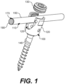
- FIG. 1 a non-limiting example of a pedicle screw 100 and a spinal rod member 110 is shown according to various embodiments.
- the pedicle screw 100 and the spinal rod member 110 can be used as a component in a spinal rod type spine fixation system or assembly, as will be appreciated.
- the pedicle screw 100 can be employed to attach or fix a section of the spinal rod member 110 or similar rod construct, plating system, or other similar system relative to a vertebrae or section of vertebra of the spine with or without fixation to the skull base, sacrum and/or pelvis (not shown). More specifically, the pedicle screw 100 is configured to be attached to a vertebra in a manner known in the art by skilled surgeons or other medical practitioners, while a pedicle screw head 120 of the pedicle screw 100 comprises a pedicle screw aperture 125 that receives, fixes, retains, and holds a section of the spinal rod member 110 therein.
- the vertebra can include vertebra of a mammal, such as a human, dog, cat, horse, or other mammal.
- the pedicle screw head 120 can be movable and repositioned relative to the pedicle screw 100.
- the pedicle screw head 120 includes a coupling element 130 that is detachable and can be attached to the pedicle screw head 120, for instance, to capture and retain the spinal rod member 110 or similar rod construct, plating system or other to the pedicle screw 100.
- the pedicle screw head 120 can be attached to a pedicle screw shaft 140, which can include threaded elements (i.e., male threaded elements) for insertion into bone, such as vertebrae or other spinal segmental anatomical locations of a spinal column or other suitable bone structure.
- Implant construct testing includes the fatigue strength of the construct over time. As such, during surgery, the spinal rod must be adjusted and bent from a predetermined shape of straight or nearly straight to form the appropriate curvature for engaging the already placed screw constructs (e.g., a pedicle screw) that also corresponds with the larger alignment of concavity and convexity desired of the spinal column.
- screw constructs e.g., a pedicle screw
- the alignment can be determined to maintain a desired alignment based on a patient's pathophysiology or to correct the alignment with subsequent fixation for healing to achieve a desired radiographic and clinical outcome.
- Manually adjusting and bending of the spinal rod can be mentally difficult to recapitulate the three-dimensional contour required for internal implantation as this process of manual bending traditionally is completed in a separate environment (over the patient or on a back table in an operating room) and is labor intensive. Spinal rod bending can significantly increase surgery times.
- a spinal rod member 110 can be formed, for instance, during a surgery on a spinal column or other portion of the body without having to bend stainless steel or other material.
- the spinal rod member 110 can include an elongated tubular membrane 150 having a flexible body.
- the elongated tubular member 150 can be formed of plastic, other semi-solid, malleable solid or other suitable material.
- the flexible body can be used, for instance, to position the elongated tubular membrane 150 in the screw head aperture 125 (or other receptacles of channels) of one or more screw heads 120.
- the coupling element 130 or other functionally similar coupling element can be used to secure the elongated tubular membrane 150 to the pedicle screws 100.
- the elongated tubular membrane 150 can include a hollow interior 170 in some embodiments.
- the elongated tubular member 150 can be formed of a material that provides some structural resistance when the coupling element 130 is attached, such that a body of the spinal rod member 110 to be formed includes a substantially uniform or a uniformity that is not statistically and/or functionally significantly different in cross-section across all portions of the spinal rod member 110.
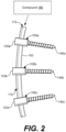
- the spinal rod member 110 can include a substantially straight shape or a curvilinear shape, as shown in FIG. 2 .
- the hollow interior 170 of the elongated tubular membrane 150 can be filled by insertion of a compound 180, as shown in FIG. 2 , such as a liquid or semisolid compound, thereby forming a spinal rod body 190 when the compound has settled and hardened.
- a compound 180 such as a liquid or semisolid compound
- the method for hardening can be one of a number of different controlled properties of the initial compound or an activation of the liquid or semi-solid compound by any of a number of external factors. The extent of potential external factors are not limited within this description. Further, as shown in FIG.
- the elongated tubular member 150 is shown as being positioned in channels 160 of multiple pedicle screws 100a...100c, where the pedicle screws 100a...100c include pedicle screw heads 120a...120c and pedicle screw shafts 140a...140c, as shown in FIG. 1 .
- the compound includes polymethylmethacrylate (PMMA) or other suitable compound. Additional embodiments would include yet to be developed easily influenced liquids, semi-solid, solid compounds, or a combination thereof, that be converted into a rigid state in a fashion that can be implanted for the purposes of spinal instrumentation and fixation.
- PMMA polymethylmethacrylate
- the elongated spinal rod body 110 can represent a multi-segmented flexible and elongated rod that will be positioned in channels 160 of multiple pedicle screws 100a...100c, where the pedicle screws 100a...100c include pedicle screw heads 120a...120c and pedicle screw shafts 140a...140c. After capturing the rod within the pedicle screw head 160 with screw cap 130, the multi-segmented flexible rod will be made rigid by a collapsing process of the segments to a rigid construct.
- the number of pedicle screw 100 segments fixed at an individual procedure is only limited by the surgical plan of the specialty surgeon and the anatomy of the patient. All embodiments detailed here can be used for fixation of any number of vertebral segments including fixation to the skull, sacrum and pelvis.
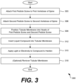
- a flowchart 300 is shown as an example of forming a spinal rod member 110 for use with one or more pedicle screws 100.
- the method (not claimed) can include attaching a first pedicle screw 100a to a first vertebrae of a spine (not shown).
- the method can include attaching a second pedicle screw 100b to a second vertebrae of the spine (not shown).
- the first pedicle screw 100a and the second pedicle screw 100b can each include a pedicle screw head 120 and a pedicle screw shaft 140, as can be appreciated.
- pedicle screw head 120 of the first pedicle screw 100a and the second pedicle screw 100b can be configured to retain a spinal rod member 110 relative to the first pedicle screw 100a and the second pedicle screw 100b.
- pedicle screw 100b can be configured to retain a spinal rod member 110 relative to a third pedicle screw 100c which will continue to retain a spinal rod member 110 relative to pedicle screw 100d.
- the spinal rod member 110 can be formed.
- a flexible and elongated tubular membrane 150 can be positioned into the pedicle screw heads 120 of the first pedicle screw 100a and the second pedicle screw 100b (or other pedicle screws 100 as needed).
- a compound 180 such as a liquid, semi-solid or flexible solid compound configured to harden over time, can be inserted into the elongated tubular membrane 150.
- the compound 180 can be hardened, for instance, to form a hardened spinal rod member body.
- changes in temperature, light or electricity that aid or achieves the hardening of the compound 180 can be applied.
- the tubular membrane 150 can be optionally removed, although, in some embodiments, it is understood that the tubular membrane 150 can be left intact. Thereafter, the process can proceed to completion.
- Disjunctive language such as the phrase "at least one of X, Y, or Z," unless specifically stated otherwise, is otherwise understood with the context as used in general to present that an item, term, etc., can be either X, Y, or Z, or any combination thereof ( e.g ., X, Y, and/or Z). Thus, such disjunctive language is not generally intended to, and should not, imply that certain embodiments require at least one of X, at least one of Y, or at least one of Z to each be present.
Landscapes
- Health & Medical Sciences (AREA)
- Orthopedic Medicine & Surgery (AREA)
- Life Sciences & Earth Sciences (AREA)
- Neurology (AREA)
- Surgery (AREA)
- Veterinary Medicine (AREA)
- Public Health (AREA)
- General Health & Medical Sciences (AREA)
- Animal Behavior & Ethology (AREA)
- Molecular Biology (AREA)
- Medical Informatics (AREA)
- Heart & Thoracic Surgery (AREA)
- Biomedical Technology (AREA)
- Engineering & Computer Science (AREA)
- Nuclear Medicine, Radiotherapy & Molecular Imaging (AREA)
- Chemical & Material Sciences (AREA)
- Chemical Kinetics & Catalysis (AREA)
- Dermatology (AREA)
- Medicinal Chemistry (AREA)
- Oral & Maxillofacial Surgery (AREA)
- Transplantation (AREA)
- Epidemiology (AREA)
- Surgical Instruments (AREA)
Description
- This application claims the benefit of and priority to
U.S. Provisional Patent Application No. 62/655,855 entitled "TEMPORARILY FLEXIBLE IMPLANTABLE ROD PLACEMENT AND FABRICATION," filed April 11, 2018 - Surgical screw-based rod instrumentation in specialty surgery, i.e. pedicle screws, are surgically implanted medical devices that include, but are not limited to, a specialized screw commonly used in spine surgery for the stabilization of spinal sections. This intervention is commonly performed to produce spinal stability for neuronal function preservation, pain relief, deformity correction, etc. In conventional spinal instrumentation, the screw and rod construction is composed of multiple components which generally includes a screw head, a closure cap, a screw shaft, and a spinal rod which is used to connect two or more screws together in a segmental or non-segmental series.
- The metal alloy composition of the spinal rod is usually stainless steel, titanium, cobalt chromium or other, though other compounds with less rigid composition have also been developed. Internal anatomy and pathophysiology differs widely and no two individuals requiring surgery have uniform spinal alignment. Additionally, intentional correction of undesired spinal alignment requires the development of a personalized rod structure. Additional surgery, during which connection of a construct with a previously implanted construct, requires real-time adjustments of implanted metal. Lastly, there are also changing variables to rod alignment based on the surgical technique and comfort level of the operating surgeon.
- As such, during surgery the spinal rod must be adjusted and bent from predetermined shape of straight or nearly straight to form the appropriate curvature for engaging the already placed screw constructs, i.e. pedicle screw, that also corresponds with the larger alignment of concavity and convexity desired for the spinal column. This process requires a traditional manual manipulation of the rod or repositioning of implanted screws. This is labor intensive, and bending the spinal rod can be mentally difficult. Attempting to recapitulate the three dimensional contour required for implantation is done in a separated environment (over the patient or on the back table). This is labor intensive and it can also significantly increase surgery times. This process requires a great degree of trial-and-error until the curvature of the spinal rod is matched the internal or desired internal alignment. Of note, a similar process can be required in a number of additional surgical specialties, as this specifically speaks to spinal fixation.
- The present invention relates generally to spinal fixation devices for the internal fixation of the spine, particularly within the fields of neurosurgery, orthopedics, and other fields associated with spinal alignment procedures and spinal implants that include pedicle screws, lateral mass screws, anterior, lateral, oblique spinal screws, occipital, sacral and pelvic fixation and spinal rods for fixing, correcting and retaining vertebral bones relative to one another.
- Various embodiments are disclosed for forming spinal rod members for use in pedicle screws; lateral mass screws; trans-articular screws; cortical screws; laminar screws; facet screws; anterior, lateral and oblique screws; occipital, sacral and pelvic fixation screws (from now on generally referred to as a "pedicle screw") for spinal instrumentation and fixation surgery and systems. A particular pedicle screw system can include a pedicle screw having a pedicle screw head and a pedicle screw shaft, the pedicle screw head being configured to receive and retain a spinal rod member relative to the pedicle screw. The spinal rod member can include a predetermined rigid rod configuration, an elongated tubular membrane having a flexible body and a spinal rod body formed of a compound, where the spinal rod body is formed by insertion of a liquid compound into the elongated tubular membrane and a hardening of the liquid compound. The pedicle screw head can include a channel or an aperture configured to receive and retain the spinal rod member relative to the pedicle screw and relative to bone.
- Further, but not claimed, a method can include attaching a first pedicle screw to a first vertebrae of a spine and attaching a second pedicle screw to a second vertebrae of the spine, where the first pedicle screw and the second pedicle screw each include a pedicle screw head and a pedicle screw shaft. The pedicle screw head can be configured to retain a spinal rod member relative to the first pedicle screw and the second pedicle screw. Further, the method can include forming the spinal rod member by positioning a flexible and elongated tubular membrane that will maintain a competent inner channel into the pedicle screw head of the first pedicle screw and the second pedicle screw, inserting a liquid compound into the elongated tubular membrane, hardening the liquid compound to form a hardened spinal rod member body. Additional embodiments can include forming the spinal rod member by positioning a multi-segmented flexible and elongated rod to the pedicle screw head of the first pedicle screw and the second screw that after capturing the rod within the pedicle screw head will then made rigid by a collapsing of the segments to a rigid construct. Additional embodiments would include yet to be developed easily influenced liquids, semi-solid or solid compounds that can be converted into a rigid state in a fashion that can be implanted for the purposes of spinal instrumentation and fixation
- The present invention is defined in claim 1 and claim 6 while preferred embodiments are set forth in the dependent claims. Associated surgical methods are also described herein to aid understanding the invention. The present disclosure can be better understood with reference to the following drawings. The components in the drawings are not necessarily to scale, with emphasis instead being placed upon clearly illustrating the principles of the disclosure. Moreover, in the drawings, like reference numerals designate corresponding parts throughout the several views.
-
FIG. 1 shows an example of a pedicle screw having a spinal rod member according to various embodiments of the present disclosure. -
FIG. 2 shows an example of multiple pedicle screws having a spinal rod member forming a curvature according to various embodiments of the present disclosure. -
FIG. 3 shows a flowchart illustrating an example of the forming of a spinal rod member for use with the pedicle screws ofFIGS. 1 and2 according to various embodiments of the present disclosure. - The present disclosure relates to a pedicle screw spinal rod placement system that includes a temporarily flexible member and a method of fabricating the same. A pedicle screw as outlined in this disclosure represents a number of screw fixation techniques utilized in the fixation and stabilization of the spinal columns and includes open, percutaneous, minimally invasive and other surgical techniques. Other similar screw types used for stabilization that are also represented within the identification of "pedicle screw" include, but are not limited to, lateral mass screw; trans-articular screw; cortical screw; laminar screw; facet screw; anterior, lateral and oblique screw; and occipital, sacral and pelvic fixation, though the specifics of screw differentiation will not be discussed here.
- As noted above, pedicle screws are medically implanted surgical devices that include a specialized screw commonly used in surgery for the stabilization of spinal sections to create spinal stability, correct pathologic spinal alignment, achieve preservation or improvement of neuronal or other medically dependent function, and/or to relieve or alleviate pain. In conventional screw fixation, the screw is composed of multiple basic components generally including, but not limited to, a screw head which can be in a fixed orientation to polyaxial in nature, a closure cap or entrapment construct to house the spinal rod construct, a shaft with a variety in pitch for thread development, and a spinal rod which is used to connect two or more screws together in a non-segmental or segmental series. The spinal rod characteristics typically represent an elongated rod implant that is cylinder in shape and can be of various lengths, though other embodiments include a less circular shape, plating type system or other type devices used to connect vertebral segments. The spinal rod is usually composed of a type of stainless steel, including but not limited to, titanium or cobalt chromium, though additional less or more rigid rod composition is sometimes employed.
- Historically, certain systems used for spinal fixation have been referred to as a Harrington rod. As such, during surgery the spinal rod must be adjusted and bent from a predetermined shape of straight or nearly straight to form the appropriate curvature for engaging the already placed screw constructs, i.e. pedicle screw, that also corresponds with the larger alignment of concavity and convexity desired of the spinal column. This alignment can be determined to maintain a currently determined alignment based on a patient's pathophysiology or to correct the alignment with subsequent fixation for healing to achieve a desired radiographic and clinical outcome.
- The process of spinal rod adjustment traditionally requires a manual manipulation of the rod or repositioning of implanted screws. Manually adjusting and bending of the spinal rod can be mentally difficult to recapitulate the three-dimensional contour required for internal implantation, as this process of manual bending traditionally is completed in a separate environment (over the patient or on the back table) and is labor intensive. In situ spinal rod bending is also difficult and potentially hazardous as large amounts of force are required with instruments that can be difficult to get into the surgical site. Spinal rod bending can significantly increase surgery times. This process requires a great degree of trial-and-error until the curvature of the spinal rod can match the implanted and desired internal anatomy. In addition, a similar process of trial-and-error can be required in a number of other surgical procedures for implantation of a rigid construct to allow for correction and stabilization of physiologic structures though this document specifically speaks to spinal fixation.
- Accordingly, various embodiments are disclosed regarding the forming of spinal rod members for use in pedicle screw systems during spinal fixation surgery. In addition, various embodiments are disclosed regarding the systems that require improved techniques for adjusting and do not require manual bending of stainless steel metal spinal rods or other members. A system can include a pedicle screw having a pedicle screw head and a pedicle screw shaft, where the pedicle screw head is configured to receive and retain a spinal rod member relative to the pedicle screw. The spinal rod member can include an elongated tubular membrane having a flexible body and a spinal rod body formed of a single element or compound, including but not limited to a derivative of a plastic compound, primary element, metal alloy, other compound or other, where the spinal rod body is formed by insertion of a liquid compound into the elongated tubular membrane and a hardening of the liquid compound.
- The hardening process of the liquid compound can comprise a number of potential methods. Methods can include, but are not necessarily limited to, waiting a predetermined amount of time, an application of an additional agent that invokes a chemical reaction to harden the liquid compound, photo or electrical curation, a multistep process of hardening, metal alloy selection that has intrinsic properties for hardening, use of other element or compound that has innate or adjustable properties that can be manipulated or adjusted in a controlled fashion to convert from a first state that can easily be maneuvered to a more rigid state, temperature curing methods, a combination thereof, or other currently established or future developed procedures for conversion of a malleable/flexible rod to a rigid structure whether this process is completed within the surgical wound or outside the surgical wound for implantation. The tensile and fatigue strength of the spinal rod can be variable and can depend on the desired rigidity of the rod based on previous surgery, the surgical expectations by the surgical team and long-term goals of the construct. The pedicle screw head can include a channel configured to receive and retain the spinal rod member, as can be appreciated.
- Further, but not claimed, a method can include attaching a first pedicle screw to a first vertebrae of a spine and attaching a second pedicle screw to a second vertebrae of the spine, where the first pedicle screw and the second pedicle screw each include a pedicle screw head and a pedicle screw shaft that can be cannulated, pores or not. The rigid or polyaxial pedicle screw head can be configured to retain a spinal rod member relative to the first pedicle screw and the second pedicle screw. Further, the method can include forming the spinal rod member by positioning a flexible and elongated tubular membrane into the pedicle screw head of the first pedicle screw and the second pedicle screw, inserting a liquid compound into the elongated tubular membrane, hardening the liquid compound to form a hardened spinal rod member body. Additional embodiments can include forming the spinal rod member by positioning a multi-segmented flexible and elongated rod to the pedicle screw head of the first pedicle screw and the second screw that after capturing the rod within the pedicle screw head will then be made rigid by a collapsing of the segments to a rigid construct. Additional embodiments can further include yet to be developed easily influenced liquids, semi-solid, or solid compounds that can be converted into a rigid state in a fashion that can be implanted for the purposes of spinal instrumentation and fixation.
- Turning now to
FIG. 1 , a non-limiting example of apedicle screw 100 and aspinal rod member 110 is shown according to various embodiments. Thepedicle screw 100 and thespinal rod member 110 can be used as a component in a spinal rod type spine fixation system or assembly, as will be appreciated. - More specifically, the
pedicle screw 100, similar screw implant, or other similar apparatus can be employed to attach or fix a section of thespinal rod member 110 or similar rod construct, plating system, or other similar system relative to a vertebrae or section of vertebra of the spine with or without fixation to the skull base, sacrum and/or pelvis (not shown). More specifically, thepedicle screw 100 is configured to be attached to a vertebra in a manner known in the art by skilled surgeons or other medical practitioners, while apedicle screw head 120 of thepedicle screw 100 comprises apedicle screw aperture 125 that receives, fixes, retains, and holds a section of thespinal rod member 110 therein. It is understood that the vertebra can include vertebra of a mammal, such as a human, dog, cat, horse, or other mammal. In some embodiments, thepedicle screw head 120 can be movable and repositioned relative to thepedicle screw 100. - Further, in some embodiments, the
pedicle screw head 120 includes acoupling element 130 that is detachable and can be attached to thepedicle screw head 120, for instance, to capture and retain thespinal rod member 110 or similar rod construct, plating system or other to thepedicle screw 100. Thepedicle screw head 120 can be attached to apedicle screw shaft 140, which can include threaded elements (i.e., male threaded elements) for insertion into bone, such as vertebrae or other spinal segmental anatomical locations of a spinal column or other suitable bone structure. - As noted above, conventional spinal rod implants or Harrington rods including screws, rods, hooks and connectors are composed of stainless steel or other type of metal or high tensile strength materials. Implant construct testing includes the fatigue strength of the construct over time. As such, during surgery, the spinal rod must be adjusted and bent from a predetermined shape of straight or nearly straight to form the appropriate curvature for engaging the already placed screw constructs (e.g., a pedicle screw) that also corresponds with the larger alignment of concavity and convexity desired of the spinal column.
- The alignment can be determined to maintain a desired alignment based on a patient's pathophysiology or to correct the alignment with subsequent fixation for healing to achieve a desired radiographic and clinical outcome. This commonly requires bending of a particular rod in multiple three-dimensional directions for proper implantation. The process of spinal rod adjustment traditionally requires a manual manipulation of the rod or repositioning of implanted screws. Manually adjusting and bending of the spinal rod can be mentally difficult to recapitulate the three-dimensional contour required for internal implantation as this process of manual bending traditionally is completed in a separate environment (over the patient or on a back table in an operating room) and is labor intensive. Spinal rod bending can significantly increase surgery times. This process requires a great degree of trial-and-error until the three-dimensional curvature of the spinal rod can match the implanted and desired internal anatomy. As such, according to various embodiments of the present disclosure, a
spinal rod member 110 can be formed, for instance, during a surgery on a spinal column or other portion of the body without having to bend stainless steel or other material. - In various embodiments, the
spinal rod member 110 can include an elongatedtubular membrane 150 having a flexible body. In some embodiments, theelongated tubular member 150 can be formed of plastic, other semi-solid, malleable solid or other suitable material. The flexible body can be used, for instance, to position the elongatedtubular membrane 150 in the screw head aperture 125 (or other receptacles of channels) of one or more screw heads 120. In some embodiments, after theelongated tubular member 150 is positioned in the channels 160, thecoupling element 130 or other functionally similar coupling element can be used to secure the elongatedtubular membrane 150 to the pedicle screws 100. The elongatedtubular membrane 150 can include ahollow interior 170 in some embodiments. As such, theelongated tubular member 150 can be formed of a material that provides some structural resistance when thecoupling element 130 is attached, such that a body of thespinal rod member 110 to be formed includes a substantially uniform or a uniformity that is not statistically and/or functionally significantly different in cross-section across all portions of thespinal rod member 110. Thespinal rod member 110 can include a substantially straight shape or a curvilinear shape, as shown inFIG. 2 . - In one embodiment the
hollow interior 170 of the elongatedtubular membrane 150 can be filled by insertion of acompound 180, as shown inFIG. 2 , such as a liquid or semisolid compound, thereby forming aspinal rod body 190 when the compound has settled and hardened. The method for hardening can be one of a number of different controlled properties of the initial compound or an activation of the liquid or semi-solid compound by any of a number of external factors. The extent of potential external factors are not limited within this description. Further, as shown inFIG. 2 , theelongated tubular member 150 is shown as being positioned in channels 160 ofmultiple pedicle screws 100a...100c, where thepedicle screws 100a...100c include pedicle screw heads 120a...120c andpedicle screw shafts 140a...140c, as shown inFIG. 1 . Referring again toFIG. 2 , in some embodiments, the compound includes polymethylmethacrylate (PMMA) or other suitable compound. Additional embodiments would include yet to be developed easily influenced liquids, semi-solid, solid compounds, or a combination thereof, that be converted into a rigid state in a fashion that can be implanted for the purposes of spinal instrumentation and fixation. - In another embodiment, the elongated
spinal rod body 110 can represent a multi-segmented flexible and elongated rod that will be positioned in channels 160 ofmultiple pedicle screws 100a...100c, where thepedicle screws 100a...100c include pedicle screw heads 120a...120c andpedicle screw shafts 140a...140c. After capturing the rod within the pedicle screw head 160 withscrew cap 130, the multi-segmented flexible rod will be made rigid by a collapsing process of the segments to a rigid construct. - In any spinal construct, the number of
pedicle screw 100 segments fixed at an individual procedure is only limited by the surgical plan of the specialty surgeon and the anatomy of the patient. All embodiments detailed here can be used for fixation of any number of vertebral segments including fixation to the skull, sacrum and pelvis. - Referring next to
FIG. 3 , aflowchart 300 is shown as an example of forming aspinal rod member 110 for use with one or more pedicle screws 100. Beginning withstep 303, the method (not claimed) can include attaching afirst pedicle screw 100a to a first vertebrae of a spine (not shown). Next, instep 306, the method can include attaching asecond pedicle screw 100b to a second vertebrae of the spine (not shown). Thefirst pedicle screw 100a and thesecond pedicle screw 100b can each include apedicle screw head 120 and apedicle screw shaft 140, as can be appreciated. Further, thepedicle screw head 120 of thefirst pedicle screw 100a and thesecond pedicle screw 100b can be configured to retain aspinal rod member 110 relative to thefirst pedicle screw 100a and thesecond pedicle screw 100b. In a similarfashion pedicle screw 100b can be configured to retain aspinal rod member 110 relative to athird pedicle screw 100c which will continue to retain aspinal rod member 110 relative to pedicle screw 100d. - Next, with respect to
steps 309 tosteps 318, thespinal rod member 110 can be formed. For instance, with respect to step 309, a flexible and elongatedtubular membrane 150 can be positioned into the pedicle screw heads 120 of thefirst pedicle screw 100a and thesecond pedicle screw 100b (orother pedicle screws 100 as needed). Next, instep 312, acompound 180, such as a liquid, semi-solid or flexible solid compound configured to harden over time, can be inserted into the elongatedtubular membrane 150. Instep 315, thecompound 180 can be hardened, for instance, to form a hardened spinal rod member body. Instep 315, in some embodiments, changes in temperature, light or electricity that aid or achieves the hardening of thecompound 180 can be applied. Instep 318, thetubular membrane 150 can be optionally removed, although, in some embodiments, it is understood that thetubular membrane 150 can be left intact. Thereafter, the process can proceed to completion. - Disjunctive language such as the phrase "at least one of X, Y, or Z," unless specifically stated otherwise, is otherwise understood with the context as used in general to present that an item, term, etc., can be either X, Y, or Z, or any combination thereof (e.g., X, Y, and/or Z). Thus, such disjunctive language is not generally intended to, and should not, imply that certain embodiments require at least one of X, at least one of Y, or at least one of Z to each be present.
- It should be emphasized that the above-described embodiments of the present disclosure are merely possible examples of implementations set forth for a clear understanding of the principles of the disclosure. Many variations and modifications can be made to the above-described embodiment(s) without departing substantially from the spirit and principles of the disclosure.
Claims (10)
- A system, comprising:a spinal rod member (110); anda pedicle screw (100), comprising:a pedicle screw head (120);a pedicle screw shaft (140) for implanting the pedicle screw (100) in vertebra of a mammalian body; anda pedicle screw aperture (125), the pedicle screw aperture (125) being configured to receive and retain the spinal rod member (110) relative to the pedicle screw (100); anda coupling element (130) attachable to the pedicle screw head (120), the coupling element (130) being configured to secure the spinal rod member (110) within the pedicle screw aperture (125);wherein the spinal rod member (110) comprises:an elongated tubular membrane (150) having a flexible body, the elongated tubular membrane (150) being removable from the spinal rod member (110); anda spinal rod body (190) detachable from the elongated tubular membrane (150) and formed of a hardened compound (180) having a liquid, semi-solid, or flexible compound hardened into the flexible body and converted into a solid body through a hardening, wherein the elongated tubular membrane (150) is removable and is configured to be removed from the spinal rod member (110) after the spinal rod body (190) is formed and converted into the solid body.
- The system of claim 1, wherein the hardened compound (180) is formed by applying at least one of: a change in temperature of the compound (180), an application of light to the compound (180), an application of electricity to the compound (180), and an application of a hardening agent to the compound (180).
- The system of claim 1, wherein the compound (180) comprises polymethylmethacrylate (PMMA).
- The system of claim 1, wherein a cross-section of the elongated tubular membrane (150) is substantially similar to a cross-section of the pedicle screw aperture (125) that receives and retains the spinal rod member (110).
- The system of claim 1, wherein the spinal rod member (110) has a substantially straight shape or a curvilinear shape.
- A method of manufacture of a system, comprising:providing a spinal rod member (110) and a pedicle screw (100), wherein the pedicle screw (100) comprises:a pedicle screw head (120);a pedicle screw shaft (140) for implanting the pedicle screw (100) in vertebra of a mammalian body; anda pedicle screw aperture (125), the pedicle screw aperture (125) being configured to receive and retain the spinal rod member (110) relative to the pedicle screw (100); andwherein the spinal rod member (110) comprises:an elongated tubular membrane (150) having a flexible body, the elongated tubular membrane (150) being removable from the spinal rod member (110); anda spinal rod body (190) detachable from the elongated tubular membrane (150) and formed inside the flexible body by a hardening of a compound (180), wherein the spinal rod body (110) is formed by an insertion of a liquid, semi-solid, or flexible compound into the flexible body and converted into a solid; andwherein the elongated tubular membrane (150) is removable from the spinal rod member (110) through a detachment of the elongated tubular membrane (150) from the spinal rod body (110) after the hardening; andproviding a coupling element (130) attachable to the pedicle screw head (120), the coupling element (130) being configured to secure the spinal rod member (110) within the pedicle screw aperture (120).
- The method of claim 6, wherein the compound (180) comprises polymethylmethacrylate (PMMA).
- The method of claim 6, wherein a cross-section of the elongated tubular membrane (150) is substantially similar to a cross-section of the screw head aperture (125) that receives and retains the spinal rod member (110).
- The method of claim 6, wherein the spinal rod member (110) has a substantially straight shape or a curvilinear shape.
- The method of claim 6, wherein the hardening of the liquid compound (180) is performed by applying at least one of: a change in temperature of the compound (180), an application of light to the compound (180), an application of electricity to the compound (180), and an application of a hardening agent to the compound (180).
Applications Claiming Priority (2)
| Application Number | Priority Date | Filing Date | Title |
|---|---|---|---|
| US201862655855P | 2018-04-11 | 2018-04-11 | |
| PCT/US2019/026951 WO2019200071A1 (en) | 2018-04-11 | 2019-04-11 | Temporarily flexible implantable rod placement and fabrication |
Publications (3)
| Publication Number | Publication Date |
|---|---|
| EP3773276A1 EP3773276A1 (en) | 2021-02-17 |
| EP3773276A4 EP3773276A4 (en) | 2022-01-12 |
| EP3773276B1 true EP3773276B1 (en) | 2025-04-02 |
Family
ID=68162968
Family Applications (1)
| Application Number | Title | Priority Date | Filing Date |
|---|---|---|---|
| EP19785581.0A Active EP3773276B1 (en) | 2018-04-11 | 2019-04-11 | Temporarily flexible implantable rod placement and fabrication |
Country Status (5)
| Country | Link |
|---|---|
| US (2) | US11413071B2 (en) |
| EP (1) | EP3773276B1 (en) |
| CN (1) | CN112292089B (en) |
| CA (1) | CA3096464A1 (en) |
| WO (1) | WO2019200071A1 (en) |
Families Citing this family (2)
| Publication number | Priority date | Publication date | Assignee | Title |
|---|---|---|---|---|
| US11413071B2 (en) * | 2018-04-11 | 2022-08-16 | Wonderhealth Llc | Temporarily flexible implantable rod placement and fabrication |
| WO2025120634A1 (en) * | 2023-12-04 | 2025-06-12 | Mazor Robotics Ltd. | Systems and devices for setting and fixing one or more anatomical elements |
Family Cites Families (16)
| Publication number | Priority date | Publication date | Assignee | Title |
|---|---|---|---|---|
| US5658286A (en) * | 1996-02-05 | 1997-08-19 | Sava; Garard A. | Fabrication of implantable bone fixation elements |
| US9044279B2 (en) * | 2002-03-19 | 2015-06-02 | Innovative Surgical Designs, Inc. | Device and method for expanding the spinal canal with spinal column stabilization and spinal deformity correction |
| US20050277934A1 (en) * | 2004-06-10 | 2005-12-15 | Vardiman Arnold B | Rod delivery device and method |
| KR100645377B1 (en) * | 2004-09-22 | 2006-11-15 | (주)바이오스파인 | Pedicle fixation |
| EP1841375A1 (en) * | 2005-01-26 | 2007-10-10 | AESCULAP AG & Co. KG | Self-contouring spinal rod |
| US7655026B2 (en) * | 2006-01-31 | 2010-02-02 | Warsaw Orthopedic, Inc. | Expandable spinal rods and methods of use |
| US7776075B2 (en) * | 2006-01-31 | 2010-08-17 | Warsaw Orthopedic, Inc. | Expandable spinal rods and methods of use |
| US7993404B2 (en) * | 2006-03-29 | 2011-08-09 | Warsaw Orthopedic, Inc. | Transformable spinal implants and methods of use |
| US7922746B2 (en) | 2006-08-31 | 2011-04-12 | Warsaw Orthopedic, Inc. | Spinal rod extenders and methods of use |
| US20080125777A1 (en) * | 2006-11-27 | 2008-05-29 | Warsaw Orthopedic, Inc. | Vertebral Stabilizer Having Adjustable Rigidity |
| US7875079B2 (en) * | 2006-12-14 | 2011-01-25 | Warsaw Orthopedic, Inc. | Vertebral implant containment device and methods of use |
| US8663328B2 (en) | 2006-12-21 | 2014-03-04 | Warsaw Orthopedic, Inc. | Methods for positioning a load-bearing component of an orthopedic implant device by inserting a malleable device that hardens in vivo |
| US8043339B2 (en) * | 2007-10-24 | 2011-10-25 | Zimmer Spine, Inc. | Flexible member for use in a spinal column and method for making |
| US7842040B2 (en) | 2008-01-18 | 2010-11-30 | Illuminoss Medical, Inc. | Internal bone fixation system with integrated mixer |
| US20120065691A1 (en) * | 2010-08-03 | 2012-03-15 | Simonson Peter M | Spinal implant assemblies |
| US11413071B2 (en) * | 2018-04-11 | 2022-08-16 | Wonderhealth Llc | Temporarily flexible implantable rod placement and fabrication |
-
2019
- 2019-04-11 US US17/046,093 patent/US11413071B2/en active Active
- 2019-04-11 CA CA3096464A patent/CA3096464A1/en active Pending
- 2019-04-11 EP EP19785581.0A patent/EP3773276B1/en active Active
- 2019-04-11 WO PCT/US2019/026951 patent/WO2019200071A1/en not_active Ceased
- 2019-04-11 CN CN201980035135.2A patent/CN112292089B/en active Active
-
2022
- 2022-08-15 US US17/819,823 patent/US20220387079A1/en active Pending
Also Published As
| Publication number | Publication date |
|---|---|
| EP3773276A1 (en) | 2021-02-17 |
| US20220387079A1 (en) | 2022-12-08 |
| CA3096464A1 (en) | 2019-10-17 |
| CN112292089A (en) | 2021-01-29 |
| US11413071B2 (en) | 2022-08-16 |
| CN112292089B (en) | 2024-07-05 |
| WO2019200071A1 (en) | 2019-10-17 |
| US20210030444A1 (en) | 2021-02-04 |
Similar Documents
| Publication | Publication Date | Title |
|---|---|---|
| US9364265B2 (en) | Spinal implant with a flexible extension element | |
| US6235028B1 (en) | Surgical guide rod | |
| EP2010079B1 (en) | Connector apparatus | |
| US8623022B2 (en) | Surgical instrument support system and method | |
| US8435268B2 (en) | Systems, devices and methods for the correction of spinal deformities | |
| US7976567B2 (en) | Orthopedic revision connector | |
| US8419772B2 (en) | Systems, methods and devices for correcting spinal deformities | |
| US20090171395A1 (en) | Dynamic spinal rod system | |
| US20090082775A1 (en) | Spondylolisthesis reduction system and method | |
| US20220387079A1 (en) | Temporarily flexible implantable rod placement and fabrication | |
| JP2022079758A (en) | Stabilization of surgical access ports | |
| US20090228044A1 (en) | Systems and methods for mobile spinal fixation rods | |
| KR101515724B1 (en) | Implant for treating of the spondylopathy | |
| US20250177009A1 (en) | Connector rod for correction of spinal deformity | |
| EP3332721A1 (en) | Bone fixation device for use in guided growth and as a tension band | |
| US11109894B2 (en) | Apparatus, system, and method for spinal vertebrae stabilization | |
| US20230032049A1 (en) | Systems and methods for treatment of spinal deformities |
Legal Events
| Date | Code | Title | Description |
|---|---|---|---|
| STAA | Information on the status of an ep patent application or granted ep patent |
Free format text: STATUS: THE INTERNATIONAL PUBLICATION HAS BEEN MADE |
|
| PUAI | Public reference made under article 153(3) epc to a published international application that has entered the european phase |
Free format text: ORIGINAL CODE: 0009012 |
|
| STAA | Information on the status of an ep patent application or granted ep patent |
Free format text: STATUS: REQUEST FOR EXAMINATION WAS MADE |
|
| 17P | Request for examination filed |
Effective date: 20201110 |
|
| AK | Designated contracting states |
Kind code of ref document: A1 Designated state(s): AL AT BE BG CH CY CZ DE DK EE ES FI FR GB GR HR HU IE IS IT LI LT LU LV MC MK MT NL NO PL PT RO RS SE SI SK SM TR |
|
| AX | Request for extension of the european patent |
Extension state: BA ME |
|
| DAV | Request for validation of the european patent (deleted) | ||
| DAX | Request for extension of the european patent (deleted) | ||
| A4 | Supplementary search report drawn up and despatched |
Effective date: 20211209 |
|
| RIC1 | Information provided on ipc code assigned before grant |
Ipc: A61B 17/70 20060101ALI20211203BHEP Ipc: A61B 17/68 20060101ALI20211203BHEP Ipc: A61B 17/58 20060101ALI20211203BHEP Ipc: A61B 17/56 20060101AFI20211203BHEP |
|
| GRAP | Despatch of communication of intention to grant a patent |
Free format text: ORIGINAL CODE: EPIDOSNIGR1 |
|
| STAA | Information on the status of an ep patent application or granted ep patent |
Free format text: STATUS: GRANT OF PATENT IS INTENDED |
|
| INTG | Intention to grant announced |
Effective date: 20241029 |
|
| GRAS | Grant fee paid |
Free format text: ORIGINAL CODE: EPIDOSNIGR3 |
|
| GRAA | (expected) grant |
Free format text: ORIGINAL CODE: 0009210 |
|
| STAA | Information on the status of an ep patent application or granted ep patent |
Free format text: STATUS: THE PATENT HAS BEEN GRANTED |
|
| AK | Designated contracting states |
Kind code of ref document: B1 Designated state(s): AL AT BE BG CH CY CZ DE DK EE ES FI FR GB GR HR HU IE IS IT LI LT LU LV MC MK MT NL NO PL PT RO RS SE SI SK SM TR |
|
| REG | Reference to a national code |
Ref country code: GB Ref legal event code: FG4D |
|
| REG | Reference to a national code |
Ref country code: CH Ref legal event code: EP |
|
| REG | Reference to a national code |
Ref country code: DE Ref legal event code: R096 Ref document number: 602019068141 Country of ref document: DE |
|
| REG | Reference to a national code |
Ref country code: IE Ref legal event code: FG4D |
|
| REG | Reference to a national code |
Ref country code: NL Ref legal event code: MP Effective date: 20250402 |
|
| PG25 | Lapsed in a contracting state [announced via postgrant information from national office to epo] |
Ref country code: NL Free format text: LAPSE BECAUSE OF FAILURE TO SUBMIT A TRANSLATION OF THE DESCRIPTION OR TO PAY THE FEE WITHIN THE PRESCRIBED TIME-LIMIT Effective date: 20250402 |
|
| REG | Reference to a national code |
Ref country code: AT Ref legal event code: MK05 Ref document number: 1780522 Country of ref document: AT Kind code of ref document: T Effective date: 20250402 |
|
| PG25 | Lapsed in a contracting state [announced via postgrant information from national office to epo] |
Ref country code: PT Free format text: LAPSE BECAUSE OF FAILURE TO SUBMIT A TRANSLATION OF THE DESCRIPTION OR TO PAY THE FEE WITHIN THE PRESCRIBED TIME-LIMIT Effective date: 20250804 Ref country code: ES Free format text: LAPSE BECAUSE OF FAILURE TO SUBMIT A TRANSLATION OF THE DESCRIPTION OR TO PAY THE FEE WITHIN THE PRESCRIBED TIME-LIMIT Effective date: 20250402 Ref country code: FI Free format text: LAPSE BECAUSE OF FAILURE TO SUBMIT A TRANSLATION OF THE DESCRIPTION OR TO PAY THE FEE WITHIN THE PRESCRIBED TIME-LIMIT Effective date: 20250402 |
|
| REG | Reference to a national code |
Ref country code: LT Ref legal event code: MG9D |
|
| PG25 | Lapsed in a contracting state [announced via postgrant information from national office to epo] |
Ref country code: NO Free format text: LAPSE BECAUSE OF FAILURE TO SUBMIT A TRANSLATION OF THE DESCRIPTION OR TO PAY THE FEE WITHIN THE PRESCRIBED TIME-LIMIT Effective date: 20250702 Ref country code: GR Free format text: LAPSE BECAUSE OF FAILURE TO SUBMIT A TRANSLATION OF THE DESCRIPTION OR TO PAY THE FEE WITHIN THE PRESCRIBED TIME-LIMIT Effective date: 20250703 |
|
| PG25 | Lapsed in a contracting state [announced via postgrant information from national office to epo] |
Ref country code: PL Free format text: LAPSE BECAUSE OF FAILURE TO SUBMIT A TRANSLATION OF THE DESCRIPTION OR TO PAY THE FEE WITHIN THE PRESCRIBED TIME-LIMIT Effective date: 20250402 |
|
| PG25 | Lapsed in a contracting state [announced via postgrant information from national office to epo] |
Ref country code: BG Free format text: LAPSE BECAUSE OF FAILURE TO SUBMIT A TRANSLATION OF THE DESCRIPTION OR TO PAY THE FEE WITHIN THE PRESCRIBED TIME-LIMIT Effective date: 20250402 |
|
| PG25 | Lapsed in a contracting state [announced via postgrant information from national office to epo] |
Ref country code: HR Free format text: LAPSE BECAUSE OF FAILURE TO SUBMIT A TRANSLATION OF THE DESCRIPTION OR TO PAY THE FEE WITHIN THE PRESCRIBED TIME-LIMIT Effective date: 20250402 |
|
| PG25 | Lapsed in a contracting state [announced via postgrant information from national office to epo] |
Ref country code: AT Free format text: LAPSE BECAUSE OF FAILURE TO SUBMIT A TRANSLATION OF THE DESCRIPTION OR TO PAY THE FEE WITHIN THE PRESCRIBED TIME-LIMIT Effective date: 20250402 |
|
| PG25 | Lapsed in a contracting state [announced via postgrant information from national office to epo] |
Ref country code: RS Free format text: LAPSE BECAUSE OF FAILURE TO SUBMIT A TRANSLATION OF THE DESCRIPTION OR TO PAY THE FEE WITHIN THE PRESCRIBED TIME-LIMIT Effective date: 20250702 |
|
| PG25 | Lapsed in a contracting state [announced via postgrant information from national office to epo] |
Ref country code: IS Free format text: LAPSE BECAUSE OF FAILURE TO SUBMIT A TRANSLATION OF THE DESCRIPTION OR TO PAY THE FEE WITHIN THE PRESCRIBED TIME-LIMIT Effective date: 20250802 |
|
| PG25 | Lapsed in a contracting state [announced via postgrant information from national office to epo] |
Ref country code: LV Free format text: LAPSE BECAUSE OF FAILURE TO SUBMIT A TRANSLATION OF THE DESCRIPTION OR TO PAY THE FEE WITHIN THE PRESCRIBED TIME-LIMIT Effective date: 20250402 |
|
| REG | Reference to a national code |
Ref country code: CH Ref legal event code: H13 Free format text: ST27 STATUS EVENT CODE: U-0-0-H10-H13 (AS PROVIDED BY THE NATIONAL OFFICE) Effective date: 20251125 |
|
| PG25 | Lapsed in a contracting state [announced via postgrant information from national office to epo] |
Ref country code: LU Free format text: LAPSE BECAUSE OF NON-PAYMENT OF DUE FEES Effective date: 20250411 |
|
| REG | Reference to a national code |
Ref country code: BE Ref legal event code: MM Effective date: 20250430 |
|
| REG | Reference to a national code |
Ref country code: DE Ref legal event code: R097 Ref document number: 602019068141 Country of ref document: DE |
|
| PG25 | Lapsed in a contracting state [announced via postgrant information from national office to epo] |
Ref country code: DK Free format text: LAPSE BECAUSE OF FAILURE TO SUBMIT A TRANSLATION OF THE DESCRIPTION OR TO PAY THE FEE WITHIN THE PRESCRIBED TIME-LIMIT Effective date: 20250402 Ref country code: SM Free format text: LAPSE BECAUSE OF FAILURE TO SUBMIT A TRANSLATION OF THE DESCRIPTION OR TO PAY THE FEE WITHIN THE PRESCRIBED TIME-LIMIT Effective date: 20250402 |
|
| PG25 | Lapsed in a contracting state [announced via postgrant information from national office to epo] |
Ref country code: BE Free format text: LAPSE BECAUSE OF NON-PAYMENT OF DUE FEES Effective date: 20250430 |
|
| PG25 | Lapsed in a contracting state [announced via postgrant information from national office to epo] |
Ref country code: CH Free format text: LAPSE BECAUSE OF NON-PAYMENT OF DUE FEES Effective date: 20250430 |
|
| PG25 | Lapsed in a contracting state [announced via postgrant information from national office to epo] |
Ref country code: CZ Free format text: LAPSE BECAUSE OF FAILURE TO SUBMIT A TRANSLATION OF THE DESCRIPTION OR TO PAY THE FEE WITHIN THE PRESCRIBED TIME-LIMIT Effective date: 20250402 |
|
| PG25 | Lapsed in a contracting state [announced via postgrant information from national office to epo] |
Ref country code: EE Free format text: LAPSE BECAUSE OF FAILURE TO SUBMIT A TRANSLATION OF THE DESCRIPTION OR TO PAY THE FEE WITHIN THE PRESCRIBED TIME-LIMIT Effective date: 20250402 |
|
| PG25 | Lapsed in a contracting state [announced via postgrant information from national office to epo] |
Ref country code: RO Free format text: LAPSE BECAUSE OF FAILURE TO SUBMIT A TRANSLATION OF THE DESCRIPTION OR TO PAY THE FEE WITHIN THE PRESCRIBED TIME-LIMIT Effective date: 20250402 Ref country code: SK Free format text: LAPSE BECAUSE OF FAILURE TO SUBMIT A TRANSLATION OF THE DESCRIPTION OR TO PAY THE FEE WITHIN THE PRESCRIBED TIME-LIMIT Effective date: 20250402 |
|
| PG25 | Lapsed in a contracting state [announced via postgrant information from national office to epo] |
Ref country code: IT Free format text: LAPSE BECAUSE OF FAILURE TO SUBMIT A TRANSLATION OF THE DESCRIPTION OR TO PAY THE FEE WITHIN THE PRESCRIBED TIME-LIMIT Effective date: 20250402 |
|
| PG25 | Lapsed in a contracting state [announced via postgrant information from national office to epo] |
Ref country code: MC Free format text: LAPSE BECAUSE OF FAILURE TO SUBMIT A TRANSLATION OF THE DESCRIPTION OR TO PAY THE FEE WITHIN THE PRESCRIBED TIME-LIMIT Effective date: 20250402 |
|
| PLBE | No opposition filed within time limit |
Free format text: ORIGINAL CODE: 0009261 |
|
| STAA | Information on the status of an ep patent application or granted ep patent |
Free format text: STATUS: NO OPPOSITION FILED WITHIN TIME LIMIT |
|
| REG | Reference to a national code |
Ref country code: CH Ref legal event code: L10 Free format text: ST27 STATUS EVENT CODE: U-0-0-L10-L00 (AS PROVIDED BY THE NATIONAL OFFICE) Effective date: 20260211 |
|
| 26N | No opposition filed |
Effective date: 20260105 |
|
| PG25 | Lapsed in a contracting state [announced via postgrant information from national office to epo] |
Ref country code: IE Free format text: LAPSE BECAUSE OF NON-PAYMENT OF DUE FEES Effective date: 20250411 |
|
| PG25 | Lapsed in a contracting state [announced via postgrant information from national office to epo] |
Ref country code: CY Free format text: LAPSE BECAUSE OF FAILURE TO SUBMIT A TRANSLATION OF THE DESCRIPTION OR TO PAY THE FEE WITHIN THE PRESCRIBED TIME-LIMIT Effective date: 20250402 |
|
| PG25 | Lapsed in a contracting state [announced via postgrant information from national office to epo] |
Ref country code: LT Free format text: LAPSE BECAUSE OF FAILURE TO SUBMIT A TRANSLATION OF THE DESCRIPTION OR TO PAY THE FEE WITHIN THE PRESCRIBED TIME-LIMIT Effective date: 20250402 |
|
| PGFP | Annual fee paid to national office [announced via postgrant information from national office to epo] |
Ref country code: GB Payment date: 20260423 Year of fee payment: 8 |
|
| PGFP | Annual fee paid to national office [announced via postgrant information from national office to epo] |
Ref country code: DE Payment date: 20260422 Year of fee payment: 8 |
|
| PGFP | Annual fee paid to national office [announced via postgrant information from national office to epo] |
Ref country code: FR Payment date: 20260420 Year of fee payment: 8 |
|
| PG25 | Lapsed in a contracting state [announced via postgrant information from national office to epo] |
Ref country code: SE Free format text: LAPSE BECAUSE OF FAILURE TO SUBMIT A TRANSLATION OF THE DESCRIPTION OR TO PAY THE FEE WITHIN THE PRESCRIBED TIME-LIMIT Effective date: 20250402 |