EP3773097B1 - Cookware container with removable handle - Google Patents
Cookware container with removable handle Download PDFInfo
- Publication number
- EP3773097B1 EP3773097B1 EP19785886.3A EP19785886A EP3773097B1 EP 3773097 B1 EP3773097 B1 EP 3773097B1 EP 19785886 A EP19785886 A EP 19785886A EP 3773097 B1 EP3773097 B1 EP 3773097B1
- Authority
- EP
- European Patent Office
- Prior art keywords
- section
- handle
- removable
- flange
- cookware container
- Prior art date
- Legal status (The legal status is an assumption and is not a legal conclusion. Google has not performed a legal analysis and makes no representation as to the accuracy of the status listed.)
- Active
Links
Images



Classifications
-
- A—HUMAN NECESSITIES
- A47—FURNITURE; DOMESTIC ARTICLES OR APPLIANCES; COFFEE MILLS; SPICE MILLS; SUCTION CLEANERS IN GENERAL
- A47J—KITCHEN EQUIPMENT; COFFEE MILLS; SPICE MILLS; APPARATUS FOR MAKING BEVERAGES
- A47J45/00—Devices for fastening or gripping kitchen utensils or crockery
- A47J45/06—Handles for hollow-ware articles
- A47J45/07—Handles for hollow-ware articles of detachable type
- A47J45/071—Saucepan, frying-pan handles
Definitions
- This invention generally relates to an improved design for removable cookware handles (or removable handles).
- Cookware with detachable handles are used in order to allow for more compact, effective and efficient storage of cookware.
- Removable handle cookware is typically comprised of a set of containers of different sizes and a removable handle with an attachment end that connects with a flange on the containers.
- the removable handles are used as an efficient way to conserve space and money as you can use the same handle for all containers that have an acceptable attachment point.
- the known removable handles are subject to loose connections with the attachment point which causes unwanted movement of the container when the handle is engaged.
- KR 101202930 B1 discloses a detachable handle for a cooking container with a rotating button on the top of the handle for locking or unlocking the handle.
- the present invention is defined by the features of claim 1 and provides a cookware container with a removable handle that creates a user-friendly and secure connection at its attachment point to the corresponding container.
- the removable handle for removable attachment to an attachment point on a cookware container comprises an elongated handle section.
- the elongated handle section has first and second ends, wherein at the first end of the handle section there is the means for removable attachment to the attachment point on a cookware container and a means for locking the removable handle to the attachment point.
- the attachment point on the cookware container comprises a bracket that has a depending section attached to a side wall of the cookware container and a flange at the top edge of the depending section and extending outwardly from the side wall of the cookware container.
- a non-circular elongated opening is centrally located through the flange and generally orientated with its longitudinal axis generally perpendicular to a longitudinal axis of the elongated handle section and generally parallel to the side wall of the cookware container.
- the opening is sized and shaped to engage with the means for removable attachment on the handle.
- the means for removable attachment to the attachment point comprises a horizontal body section having top and bottom surfaces and first and second ends.
- a thicker portion of the body section On the bottom surface of the body section adjacent the first end is a thicker portion of the body section, said thicker portion sized and shaped to fit snugly with the opening on the flange and in the embodiment illustrated extend below the bottom surface of the flange.
- a horizontal tab section extends outwardly from the bottom surface of the thicker portion of the body section to extend under the bottom surface of the flange when the thicker body portion is located within the opening on the flange.
- the removable handle connects to the attachment point with a locking mechanism to help keep the removable handle secure and in place while also allowing for easy removal.
- the locking mechanism to help keep the removable handle secure and in place while also allowing for easy removal comprises an elongated locking bar moveable horizontally from an unlocked position to a locked position where in the locked position, an end of the locking bar is located beneath and in contact with the bottom surface of the flange on the attachment point and wherein the elongated locking bar is biased to the locking position.
- the means for moving the elongated locking bar horizontally from an unlocked position to a locked position comprises an actuator that is located away from the natural placement of a user's thumb so as to prevent accidental movement of the actuator and accidental disengagement of the removable handle from the attachment point on the cookware container.
- a trigger section on the actuator is sized and shaped to permit engagement with a user's finger.
- the trigger section on the actuator is of sufficient height to prevent the user's hand from being placed too close to the cookware container.
- the removable handle can be used to save space and provide a secure and tight connection with the container when engaged.
- the removable handle provides versatility - the same cookware container may be used for both cooking the meal and serving or storing the meal since the ability to remove the handle allows the user to conserve surface area on the table and in the fridge.
- the removable handle for removable attachment to an attachment point on a cookware container comprises an elongated handle section.
- the elongated handle section having first and second ends. At the first end of the handle section there is means for removable attachment to the attachment point on a cookware container and a means for locking the removable. handle to the attachment point.
- the attachment point on the cookware container comprises a bracket that has a depending section attached to a side wall of the cookware container and a flange at the top edge of the depending section and extending outwardly away from the side wall of the cookware container.
- a centrally located non-circular opening is provided through the flange. The opening is sized and shaped to engage with the means for removable attachment on the handle.
- the means for removable attachment to the attachment point comprises a horizontal body section having top and bottom surfaces and first and second ends. On the bottom surface of the body section adjacent the first end is a thicker portion of the body section. The thicker portion is sized and shaped to fit snugly with the non-circular opening on the flange.
- a horizontal tab section extends outwardly from the thicker portion of the body section to extend under the bottom surface of the flange toward the cookware container when the thicker body portion is located within the non-circular opening on the flange.
- a means for locking the removable handle to the attachment point comprising an elongated locking bar moveable horizontally from an unlocked position to a locked position where an end of the locking bar is located beneath and in contact with the bottom surface of the flange,
- Another embodiment of the invention provides a cookware container with a removable handle.
- One embodiment provides a cookware container in a set of cookware containers wherein the removable handle is sized and adapted to connect to a range of sizes and weights of cookware containers in the set.
- the cookware container is one in a set of cookware containers that are stackable.
- the cookware container comprises a base and a peripheral side wall extending from the base wherein the removable handle is adapted for removable attachment to anattachment point on the cookware container.
- the attachment point on the cookware container comprises a bracket that has a depending section attached to the side wall of the cookware container and a flange at the top edge of the depending section and extending outwardly away from the side wall of the cookware container.
- a centrally located non-circular opening is provided through the flange, said opening sized and shaped to engage with means for removable attachment on the handle and said opening being elongated and generally orientated with its longitudinal axis perpendicular to a longitudina; axis of the elongated handle section of the removable handle.
- the removable handle comprises an elongated handle section that has first and second ends. At the first end of the handle section there is means for removable attachment to the attachment point on the cookware container and means for locking the removable handle to the attachment point.
- the for removable attachment to the attachment point comprises a horizontal body section having top and bottom surfaces and first and second ends. On the bottom surface of the body section adjacent the first end is adepending thicker portion of the body section.
- the thicker portion is sized and shaped to in snugly with the non-circular opening on the flance with the surrounding bottom surface of the horizontal body section placed against a top surface of the flange and a horizontal tab section that extends outwardly from the thicker portion of the body section and that extends under a bottom surface of the flange toward the cookware container when the thicker body portion is located within the non-circular opening on the flange.
- the means for locking the removable handle to the attachment point comprises an elongated locking bar moveable by an actuator horizontally from an unlocked position to a locked position where an end of the locking bar is located beneath and in contact with the bottom surface of the flange.
- One embodiment provides an elongated locking bar on the removable handle that is biased to the locking position.
- One embodiment also provides an actuator that is sized and shaped to permit engagement with a user's finger and located outside the natural placementof a user's thumb on a bottom surface of the elongated locking bar and depending below the elongated handle section so as to prevent accidental trigger of the actuator and accidental disengagement of the removable handle from the attachment point on the cookware container.
- an embodiment of a removable handle shown attached to one cookware container in a set of containers according to the present invention is generally indicated at 1.
- the removable handle 1 in the embodiment shown comprises an elongated handle section 2 having a length and width that can vary depending on the size range of the corresponding cookware.
- the elongated handle section 2 has first end 5 and second end 6.
- the embodiment illustrated shows the handle section 2 being straight from the first end 5 to second end 6 but it can also be slightly curved from end to end.
- At the firstend 5 of the elongated handle section 2 there is the means for removable attachment generally indicated at 2A to the attachment point 3 on a corresponding cookware container 4, and a means for locking the removable handle 1 to the attachment point 3.
- the attachment point 3 on the cookware container 4 consists of a bracket 30 that has depending section 10 attached to a side wall 7 of the cookware container 4 and a flange 8 at the top edge 9 of the depending section 10 and extending outwardly from the side wall 7 of the cookware container 4.
- a centrally located non-circular opening 11 is provided through the flange 8.
- the opening 11 in the embodiment illustrated is elongated and generally orientated with its longitudinal axis perpendicular to a longitudinal axis of the elongated handle section and generally parallel to the side wall 7 of the cookware container 4.
- the opening 11 is sized and shaped to engage with the means for removable attachment on the handle.
- FIG. 2 . 3 and 4 which show the removable handle and attachment point in cross section along line A-A in Figure 3 , there is the means for removable attachment 2A to the attachment point 3 on a corresponding cookware container 4, and a means for locking the removable handle to the attachment point located adjacent the first end 5 of handle section 2.
- the means for removable attachment 2A to the attachment point 3 comprises a horizontal body section 12 having top 13 and bottom 14 surfaces and first and second ends 15. 16.
- a thicker portion 17 of the body section 12 On the bottom surface 14 of the body section 12 adjacent the first end 15 is a thicker portion 17 of the body section 12 said thicker portion 17 sized and shaped to fit snugly with the opening 11 on the flange 8 and that, in the embodiment illustrated, extends below the bottom surface 18 of the flange 8.
- the width of the first end 15, the thicker portion 17 and opening 11 are sized and shaped to minimize any wobble, side to side rock or unintentional lateral movement of the removable handle relative to the attachment point.
- the elongated opening 11 is approximately twice as long as it is wide, the elongated opening 11 has rounded corners and the width of the first end 15 of the body section 12 and thicker section 17 is less than the width of flange 8.
- the horizontal cross section of the thicker section 17 is the same shape and slightly smaller than the opening 11 in the flange 8 so that it fits snugly within the opening.
- a horizontal tab section 19 extends outwardly from the first end 15 of the body section 12 adjacent the bottom surface 14 of the thicker portion 17 of the body section 12 to extend towards the cookware container 4 and under the bottom surface 18 of the flange 8 when the thicker body portion 17 is located within the opening 11 on the flange 8.
- the means for locking the removable handle 2B to the attachment point 3 comprises an elongated locking bar 22 moveable horizontally through the opening 21 in guide flange 20 from an unlocked position to a locked position where an end 23 of the locking bar 22 is located beneath and in contact with the bottom surface 18 of the flange 8.
- an axial channel 31 in handle section 2 allows elongated locking bar 22 to move horizontally from an unlocked position to a locked position.
- Spring 24 located at the end of channel 31 biases the elongated locking bar 22 to the locking position.
- An actuator 25 is located on the bottom surface of elongated locking bar 22 and depending below the handle section 2 to permit the actuator 25 to be pulled back to move elongated locking bar 22 to an unlocked position and allow removal of the removable handle 1.
- the actuator 25 is located on the bottom of the elongated handle away from natural placement of a user's thumb so as to prevent accidental movement of the actuator 25 and accidental disengagement of the removable handle 1 from the attachment point 3 on the cookware container 4.
- a locking bar slot 22A in the bottom surface of the handle section 2 in communication with the axial channel 31.
- a stem 26 extends downwardly from elongated locking bar 22 through the locking barslot 22A in the bottom surface of the handle section 2.
- a trigger section 28 sized and shaped to permit engagement with a user's finger.
- the trigger section 28 on the actuator is of sufficient height to prevent the user's hand from being placed too close to the cookware container 4.
- the means for removable attachment 2A to the attachment point 3 is fastened to the handle section 2 by any suitable means.
- a tab 32 extends outwardly from the second end 16 of the horizontal body section 12 and is sized and shaped to fit into a corresponding sized slot 29 in the first end 5 of the handle section 2 (see Figure 4 ).
- the tab 32 is secured in slot 29 by any suitable fastener or adhesive.
- the opening 11 in the flange 8 and the thicker portion 17 on the body section 12 need to be sized and shaped to create a secure connection.
- the width of the first end 15 of the body section 12 and thicker section 17 is less than the width of flange 8.
- the horizontal cross section of the thicker section 17 is the same shape and slightly smaller than the opening 11 in the flange 8 so that it fits snugly within the opening.
- the trigger section 28 on actuator 25 is pulled back so that the bottom surface of the body section 12 can contact the top surface of the flange 8.
- the removable handle 1 with horizontal tab section 19 under the bottom surface of the flange 8 is lowered so the upper body section 12 is resting on the top surface of the flange 8 with the thicker portion 17 of the body section 12 snugly located in the opening 11.
- the trigger section 28 is then released and elongated locking bar 22 moves horizontally due to the spring bias from an unlocked position to a locked position under the bottom surface of the flange 8 with actuator 25 stopped against an end 22B of locking bar slot 22A.
- the handle 1 is released from the container 4 by pulling the trigger section 28 in actuator 25 which pulls the elongated locking bar 22 from a locked position under the flange 8 to an unlocked position. In the embodiment illustrated the handle 1 is then lifted at an angle upwards so that the horizontal tab section 19 and the thicker portion 17 of the body section 12 are released from opening 11 on the flange 8. In this embodiment if the trigger section 28 is pulled back but the handle 1 is not angled upward, the handle 1 will not release. This is a safety feature to ensure in this embodiment that there is no accidental release of the handle 1 while lifting the container 4.
- the horizontal body section 12 the elongated locking bar 22 and the bracket 30 are manufactured from stainless steel.
- the actuator and the elongated handle section 2 are manufactured from non-heat conductive material for example a high temperature nylon such as Bakelite TM ,
- FIG. 8-10 another embodiment of a removable handle according to the present invention, generally indicated at 100, and having a slightly more robust design potentially suitable with larger cookware is shown.
- the removable handle 100 in the embodiment shown comprises an elongated handle section 102 having a length and width that can vary depending on the size range of the corresponding cookware.
- the elongated handle section 102 has first end 105 and second end 106.
- the embodiment illustrated shows the handle section 102 being straight from the first end 105 to second end 106 but it can also be slightly curved from end to end.
- At the first end 105 of the elongated handle section 102 there is the means for removable attachment to the attachment point 103 on a corresponding cookware container (not shown), and a means for locking the removable handle 100 to the anachment point 103.
- the attachment point 103 on the cookware container consists of a bracket 130 that has depending section 110 to be attached to a side wall of the cookware container and a flange 108 at the top edge 109 of the depending section 110 and extending outwardly from the side wall of the cookware container.
- a centrally located non-circular opening 111 is provided through the flange 108.
- the opening 111 in the embodiment illustrated is elongated and generally orientated with its longitudinal axis with its longitudinal axis perpendicular to a longitudinal axis of the elongated handle section and generally parallel to the side wall of the cookware container.
- the opening: 111 is sized and shaped to engage with the means for removable attachment on the handle.
- FIG. 9 and 10 which show the removable handle and attachment point in cross section along line A-A in Figure 9 , there is the means for removable attachment generally indicated at 102A to the attachment point 103 on a corresponding cookware container, and a means for locking the removable handle generally indicated at 102B to the attachment point 103 located adjacent the first end 105 of handle section 102.
- the means for removable attachment 102A to the attachment point 103 comprises a horizontal body section 112 having top 113 and bottom 114 surfaces and first and second ends 115, 116.
- the bottom surface 114 of the horizontal body section has chamfered edges 114A for smoother entry into the opening 111.
- a thicker portion 117 of the body section 112 On the bottom surface 114 of the body section 112 adjacent the first end 115 is a thicker portion 117 of the body section 112 said thicker portion 117 sized and shaped to fit snugly with the opening 111 on the flange 108 and that, in the embodiment illustrated, extends below the bottom surface 118 of the flange 108 and has chamfered edges 117A for smoother entry into the opening 111.
- the width of the first end 115. the thicker portion 117 and opening 111 are sized and shaped to minimize any wobble, side to side rock or unintentional lateral movement of the removable handle relative to the attachment point.
- the opening 111 is approximately twice as long as it is wide, the opening 111 has rounded corners and the width of the first end 115 of the body section 112 and thicker section 117 is less than the width of flange 108.
- the horizontal cross section of the thicker section 117 is the same shape and slightly smaller than the opening 111 in the flange 108 so that it fits snugly within the opening.
- a horizontal tab section 119 extends outwardly from the first end 115 of the body section 112 adjacent the bottom surface 114 of the thicker portion 117 of the body section 112 to extend towards the cookware container and under the bottom surface 118 of the flange 108 when the thicker body portion 117 is located within the opening 111 on the flange 108.
- the horizontal tab section 119 has chamfered edges 119A for smoother entry into the opening 111.
- the means for locking the removable handle 102B to the attachment point 103 comprises an elongated locking bar 122 moveable horizontally through the opening 121 in guide flange 120 from an unlocked position to a locked position where an end 123 of the locking bar 122 is located beneath and in contact with the bottom surface 118 of the flange 108.
- an axial channel 131 in handle section 102 allows elongated locking bar 122 to move horizontally from an unlocked position to a locked position.
- Spring 124 located at the end of channel 131 biases the elongated locking bar 122 to the locking position.
- An actuator 125 is located on the bottom surface of elongated locking bar 122 and depending below the handle section 102 to permit the actuator 125 to be pulled back to move elongated locking bar 122 to an unlocked position and allow removal of the removable handle 100.
- a locking bar slot 122A in the bottom surface of the handle section 102 in communication with the axial channel 131.
- a stem 126 extends downwardly from elongated locking bar 122 through the locking bar slot 122A in the bottom surface of the handle section 102.
- a trigger section 128 sized and shaped to permit engagement with a user's finger.
- the means for removable attachment to the attachment point is fastened to the handle section 102 by any suitable means.
- a tab 132 extends outwardly from the second end 116 of the horizontal body section 112 and is sized and shaped to fit into a corresponding sized slot 129 in the first end 105 of the handle section 102 (see Figure 10 ).
- the tab 132 is secured in slot 129 by any suitable fastener or adhesive.
- two fasteners 133,134 retain tab 132 in slot 129.
- the opening 111 in the flange 108 and the thicker portion 117 on the body section 112 need to be sized and shaped to create a secure connection.
- the width of the first end 115 of the body section 112 and thicker section 117 is less than the width of flange 108.
- the horizontal cross section of the thicker section 117 is the same shape and slightly smaller than the opening 111 in the flange 108 so that it fits snugly within the opening.
- the horizontal tab section 119 and the thicker portion 117 of the body section 112 are inserted at an angle into opening 111 on the flange 108 so that horizontal tab section 119 extends under the bottom surface 118 of the flange 108.
- the trigger section 128 on actuator 125 is pulled back so that the bottom surface of the body section 112 can contact the top surface of the flange 108.
- the removable handle 100 with horizontal tab section 119 under the bottom surface of the flange 108 is lowered so the upper body section 112 is resting on the top surface of the flange 108 with the thicker portion 117 of the body section 112 snugly located in the opening 111.
- the trigger section 128 is then released and elongated locking bar 122 moves horizontally due to the spring bias from an unlocked position to a locked position under the bottom surface of the flange 108.
- the handle 100 is released from the container by pulling the trigger section 128 on actuator 125 which pulls the elongated locking bar 122 from a locked position under the flange 108 to an unlocked position.
- the handle 100 can then be lifted at an angle upwards so that the horizontal tab section 119 and the thicker portion 117 of the body section 112 are released from opening 111 on the flange 108.
- the horizontal body section 112 the elongated locking bar 122 and the bracket 130 are manufactured from stainless steel.
- the actuator and the elongated handle section 102 are manufactured from a non-heat conducting material for example high temperature nylon such as Bakelite TM .
Landscapes
- Engineering & Computer Science (AREA)
- Food Science & Technology (AREA)
- Cookers (AREA)
- Frying-Pans Or Fryers (AREA)
Description
- This invention generally relates to an improved design for removable cookware handles (or removable handles).
- Cookware with detachable handles, more specifically removable cookware handles, are used in order to allow for more compact, effective and efficient storage of cookware. Removable handle cookware is typically comprised of a set of containers of different sizes and a removable handle with an attachment end that connects with a flange on the containers. The removable handles are used as an efficient way to conserve space and money as you can use the same handle for all containers that have an acceptable attachment point.
- The known removable handles are subject to loose connections with the attachment point which causes unwanted movement of the container when the handle is engaged.
- The usual placement of lock/unlock buttons on known removable handles is located on top of the handle where a user would normally place their thumbs and is thus subject to accidental disengagement.
KR 101202930 B1 - The present invention is defined by the features of
claim 1 and provides a cookware container with a removable handle that creates a user-friendly and secure connection at its attachment point to the corresponding container. - In one embodiment the removable handle for removable attachment to an attachment point on a cookware container comprises an elongated handle section. The elongated handle section has first and second ends, wherein at the first end of the handle section there is the means for removable attachment to the attachment point on a cookware container and a means for locking the removable handle to the attachment point. The attachment point on the cookware container comprises a bracket that has a depending section attached to a side wall of the cookware container and a flange at the top edge of the depending section and extending outwardly from the side wall of the cookware container. A non-circular elongated opening is centrally located through the flange and generally orientated with its longitudinal axis generally perpendicular to a longitudinal axis of the elongated handle section and generally parallel to the side wall of the cookware container. The opening is sized and shaped to engage with the means for removable attachment on the handle.
- The means for removable attachment to the attachment point comprises a horizontal body section having top and bottom surfaces and first and second ends. On the bottom surface of the body section adjacent the first end is a thicker portion of the body section, said thicker portion sized and shaped to fit snugly with the opening on the flange and in the embodiment illustrated extend below the bottom surface of the flange. At the first end of the horizontal body section in the embodiment illustrated, a horizontal tab section extends outwardly from the bottom surface of the thicker portion of the body section to extend under the bottom surface of the flange when the thicker body portion is located within the opening on the flange.
- In an embodiment of the invention, the removable handle connects to the attachment point with a locking mechanism to help keep the removable handle secure and in place while also allowing for easy removal.
- The locking mechanism to help keep the removable handle secure and in place while also allowing for easy removal comprises an elongated locking bar moveable horizontally from an unlocked position to a locked position where in the locked position, an end of the locking bar is located beneath and in contact with the bottom surface of the flange on the attachment point and wherein the elongated locking bar is biased to the locking position.
- The means for moving the elongated locking bar horizontally from an unlocked position to a locked position comprises an actuator that is located away from the natural placement of a user's thumb so as to prevent accidental movement of the actuator and accidental disengagement of the removable handle from the attachment point on the cookware container. A trigger section on the actuator is sized and shaped to permit engagement with a user's finger. The trigger section on the actuator is of sufficient height to prevent the user's hand from being placed too close to the cookware container.
- The removable handle can be used to save space and provide a secure and tight connection with the container when engaged.
- The removable handle provides versatility - the same cookware container may be used for both cooking the meal and serving or storing the meal since the ability to remove the handle allows the user to conserve surface area on the table and in the fridge.
- In another embodiment the removable handle for removable attachment to an attachment point on a cookware container comprises an elongated handle section. the elongated handle section having first and second ends. At the first end of the handle section there is means for removable attachment to the attachment point on a cookware container and a means for locking the removable. handle to the attachment point. The attachment point on the cookware container comprises a bracket that has a depending section attached to a side wall of the cookware container and a flange at the top edge of the depending section and extending outwardly away from the side wall of the cookware container. A centrally located non-circular opening is provided through the flange. The opening is sized and shaped to engage with the means for removable attachment on the handle. The means for removable attachment to the attachment point comprises a horizontal body section having top and bottom surfaces and first and second ends. On the bottom surface of the body section adjacent the first end is a thicker portion of the body section. The thicker portion is sized and shaped to fit snugly with the non-circular opening on the flange. A horizontal tab section extends outwardly from the thicker portion of the body section to extend under the bottom surface of the flange toward the cookware container when the thicker body portion is located within the non-circular opening on the flange. A means for locking the removable handle to the attachment point is provided comprising an elongated locking bar moveable horizontally from an unlocked position to a locked position where an end of the locking bar is located beneath and in contact with the bottom surface of the flange,
- Another embodiment of the invention provides a cookware container with a removable handle. One embodiment provides a cookware container in a set of cookware containers wherein the removable handle is sized and adapted to connect to a range of sizes and weights of cookware containers in the set. In this embodiment the cookware container is one in a set of cookware containers that are stackable. The cookware container comprises a base and a peripheral side wall extending from the base wherein the removable handle is adapted for removable attachment to anattachment point on the cookware container. The attachment point on the cookware container comprises a bracket that has a depending section attached to the side wall of the cookware container and a flange at the top edge of the depending section and extending outwardly away from the side wall of the cookware container. A centrally located non-circular opening is provided through the flange, said opening sized and shaped to engage with means for removable attachment on the handle and said opening being elongated and generally orientated with its longitudinal axis perpendicular to a longitudina; axis of the elongated handle section of the removable handle. The removable handle comprises an elongated handle section that has first and second ends. At the first end of the handle section there is means for removable attachment to the attachment point on the cookware container and means for locking the removable handle to the attachment point. The for removable attachment to the attachment point comprises a horizontal body section having top and bottom surfaces and first and second ends. On the bottom surface of the body section adjacent the first end is adepending thicker portion of the body section. The thicker portion is sized and shaped to in snugly with the non-circular opening on the flance with the surrounding bottom surface of the horizontal body section placed against a top surface of the flange and a horizontal tab section that extends outwardly from the thicker portion of the body section and that extends under a bottom surface of the flange toward the cookware container when the thicker body portion is located within the non-circular opening on the flange. The means for locking the removable handle to the attachment point comprises an elongated locking bar moveable by an actuator horizontally from an unlocked position to a locked position where an end of the locking bar is located beneath and in contact with the bottom surface of the flange. One embodiment provides an elongated locking bar on the removable handle that is biased to the locking position. One embodiment also provides an actuator that is sized and shaped to permit engagement with a user's finger and located outside the natural placementof a user's thumb on a bottom surface of the elongated locking bar and depending below the elongated handle section so as to prevent accidental trigger of the actuator and accidental disengagement of the removable handle from the attachment point on the cookware container.
- Further features of the invention will be described or will become apparent in the course of the following detailed description.
- In order that the invention may be more clearly understood, the preferred embodiments thereof will now be described in detail by way of example, with reference to the accompanying drawings, in which;
-
Figure 1 is a schematic perspective drawing of one embodiment of a removable handle according to the present invention connected and engaged at the attachment point of a container. -
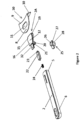
Figure 2 is an assembly drawing of the removable handle and attachment point according toFigure 1 . -
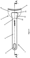
Figure 3 is a top plan view of the removable handle and attachment point shown inFigure 1 . -
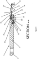
Figure 4 is a cross section of the removable handle and attachment point along line A-A inFigure 3 ; -
Figure 5 is a front plan view the removable handle and attachment point ofFigure 3 ; -
Figure 6 is a right side plan view of the removable handle and attachment point ofFigure 3 ; -
Figure 7 is a bottom perspective view of the removable handle and attachment point ofFigure 3 ; -
Figure 8 is an assembly drawing of a more robust removable handle and attachment point in the form of a bracket intended for connection to a cookware container according to the present invention; -
Figure 9 is a top plan view of the removable handle ofFigure 8 connected to the attachment point: and -
Figure 10 is a cross section of the removable handle and attachment point along line A-A inFigure 9 ; - Similar references are used in different figures to denote similar components.
- Referring to
Figure 1 , an embodiment of a removable handle shown attached to one cookware container in a set of containers according to the present invention is generally indicated at 1. Theremovable handle 1 in the embodiment shown comprises anelongated handle section 2 having a length and width that can vary depending on the size range of the corresponding cookware. Theelongated handle section 2 hasfirst end 5 andsecond end 6. The embodiment illustrated shows thehandle section 2 being straight from thefirst end 5 tosecond end 6 but it can also be slightly curved from end to end. At thefirstend 5 of theelongated handle section 2 there is the means for removable attachment generally indicated at 2A to theattachment point 3 on a corresponding cookware container 4, and a means for locking theremovable handle 1 to theattachment point 3. - The
attachment point 3 on the cookware container 4 consists of abracket 30 that has dependingsection 10 attached to a side wall 7 of the cookware container 4 and aflange 8 at thetop edge 9 of the dependingsection 10 and extending outwardly from the side wall 7 of the cookware container 4. A centrally locatednon-circular opening 11 is provided through theflange 8. Theopening 11 in the embodiment illustrated is elongated and generally orientated with its longitudinal axis perpendicular to a longitudinal axis of the elongated handle section and generally parallel to the side wall 7 of the cookware container 4. Theopening 11 is sized and shaped to engage with the means for removable attachment on the handle. - Referring to
Figure 2 .3 and4 which show the removable handle and attachment point in cross section along line A-A inFigure 3 , there is the means forremovable attachment 2A to theattachment point 3 on a corresponding cookware container 4, and a means for locking the removable handle to the attachment point located adjacent thefirst end 5 ofhandle section 2. The means forremovable attachment 2A to theattachment point 3 comprises ahorizontal body section 12 havingtop 13 and bottom 14 surfaces and first and second ends 15. 16. - On the
bottom surface 14 of thebody section 12 adjacent thefirst end 15 is athicker portion 17 of thebody section 12 saidthicker portion 17 sized and shaped to fit snugly with theopening 11 on theflange 8 and that, in the embodiment illustrated, extends below thebottom surface 18 of theflange 8. The width of thefirst end 15, thethicker portion 17 andopening 11 are sized and shaped to minimize any wobble, side to side rock or unintentional lateral movement of the removable handle relative to the attachment point. In the embodiment illustrated theelongated opening 11 is approximately twice as long as it is wide, theelongated opening 11 has rounded corners and the width of thefirst end 15 of thebody section 12 andthicker section 17 is less than the width offlange 8. The horizontal cross section of thethicker section 17 is the same shape and slightly smaller than theopening 11 in theflange 8 so that it fits snugly within the opening. Ahorizontal tab section 19 extends outwardly from thefirst end 15 of thebody section 12 adjacent thebottom surface 14 of thethicker portion 17 of thebody section 12 to extend towards the cookware container 4 and under thebottom surface 18 of theflange 8 when thethicker body portion 17 is located within theopening 11 on theflange 8. - Referring to
Figure 2 , at thesecond end 16 of thebody section 12 is dependingguide flange 20 having anopening 21 to accommodate means for locking the removable handle generally indicated at 2B to theattachment point 3. The means for locking theremovable handle 2B to theattachment point 3 comprises an elongated lockingbar 22 moveable horizontally through theopening 21 inguide flange 20 from an unlocked position to a locked position where anend 23 of the lockingbar 22 is located beneath and in contact with thebottom surface 18 of theflange 8. As best shown inFigure 4 , anaxial channel 31 inhandle section 2 allows elongated lockingbar 22 to move horizontally from an unlocked position to a locked position.Spring 24 located at the end ofchannel 31 biases the elongated lockingbar 22 to the locking position. - An
actuator 25 is located on the bottom surface of elongated lockingbar 22 and depending below thehandle section 2 to permit theactuator 25 to be pulled back to move elongated lockingbar 22 to an unlocked position and allow removal of theremovable handle 1. Theactuator 25 is located on the bottom of the elongated handle away from natural placement of a user's thumb so as to prevent accidental movement of theactuator 25 and accidental disengagement of theremovable handle 1 from theattachment point 3 on the cookware container 4. In order for theactuator 25 to be pulled back there is a lockingbar slot 22A in the bottom surface of thehandle section 2 in communication with theaxial channel 31. Astem 26 extends downwardly from elongated lockingbar 22 through the lockingbarslot 22A in the bottom surface of thehandle section 2. At thedistal end 27 ofstem 26 is atrigger section 28 sized and shaped to permit engagement with a user's finger. Thetrigger section 28 on the actuator is of sufficient height to prevent the user's hand from being placed too close to the cookware container 4. - The means for
removable attachment 2A to theattachment point 3 is fastened to thehandle section 2 by any suitable means. In the embodiment illustrated atab 32 extends outwardly from thesecond end 16 of thehorizontal body section 12 and is sized and shaped to fit into a correspondingsized slot 29 in thefirst end 5 of the handle section 2 (seeFigure 4 ). Thetab 32 is secured inslot 29 by any suitable fastener or adhesive. - The
opening 11 in theflange 8 and thethicker portion 17 on thebody section 12 need to be sized and shaped to create a secure connection. As noted above in the embodiment illustrated, the width of thefirst end 15 of thebody section 12 andthicker section 17 is less than the width offlange 8. The horizontal cross section of thethicker section 17 is the same shape and slightly smaller than theopening 11 in theflange 8 so that it fits snugly within the opening. To attach theremovable handle 1 to theattachment point 3. thehorizontal tab section 19 and thethicker portion 17 of thebody section 12 are inserted at an angle into opening 11 on theflange 8 so thathorizontal tab section 19 extends under thebottom surface 18 of theflange 8. At the same time thetrigger section 28 onactuator 25 is pulled back so that the bottom surface of thebody section 12 can contact the top surface of theflange 8. Theremovable handle 1 withhorizontal tab section 19 under the bottom surface of theflange 8 is lowered so theupper body section 12 is resting on the top surface of theflange 8 with thethicker portion 17 of thebody section 12 snugly located in theopening 11. Thetrigger section 28 is then released and elongated lockingbar 22 moves horizontally due to the spring bias from an unlocked position to a locked position under the bottom surface of theflange 8 withactuator 25 stopped against anend 22B of lockingbar slot 22A. - The
handle 1 is released from the container 4 by pulling thetrigger section 28 inactuator 25 which pulls the elongated lockingbar 22 from a locked position under theflange 8 to an unlocked position. In the embodiment illustrated thehandle 1 is then lifted at an angle upwards so that thehorizontal tab section 19 and thethicker portion 17 of thebody section 12 are released from opening 11 on theflange 8. In this embodiment if thetrigger section 28 is pulled back but thehandle 1 is not angled upward, thehandle 1 will not release. This is a safety feature to ensure in this embodiment that there is no accidental release of thehandle 1 while lifting the container 4. - In the embodiment illustrated the
horizontal body section 12, the elongated lockingbar 22 and thebracket 30 are manufactured from stainless steel. The actuator and theelongated handle section 2 are manufactured from non-heat conductive material for example a high temperature nylon such as Bakelite™, - Referring to
Figures 8-10 , another embodiment of a removable handle according to the present invention, generally indicated at 100, and having a slightly more robust design potentially suitable with larger cookware is shown. Theremovable handle 100 in the embodiment shown comprises anelongated handle section 102 having a length and width that can vary depending on the size range of the corresponding cookware. Theelongated handle section 102 hasfirst end 105 andsecond end 106. The embodiment illustrated shows thehandle section 102 being straight from thefirst end 105 tosecond end 106 but it can also be slightly curved from end to end. At thefirst end 105 of theelongated handle section 102 there is the means for removable attachment to theattachment point 103 on a corresponding cookware container (not shown), and a means for locking theremovable handle 100 to theanachment point 103. - The
attachment point 103 on the cookware container consists of abracket 130 that has dependingsection 110 to be attached to a side wall of the cookware container and aflange 108 at thetop edge 109 of the dependingsection 110 and extending outwardly from the side wall of the cookware container. A centrally locatednon-circular opening 111 is provided through theflange 108. Theopening 111 in the embodiment illustrated is elongated and generally orientated with its longitudinal axis with its longitudinal axis perpendicular to a longitudinal axis of the elongated handle section and generally parallel to the side wall of the cookware container. The opening: 111 is sized and shaped to engage with the means for removable attachment on the handle. - Referring to
Figure. 9 and 10 which show the removable handle and attachment point in cross section along line A-A inFigure 9 , there is the means for removable attachment generally indicated at 102A to theattachment point 103 on a corresponding cookware container, and a means for locking the removable handle generally indicated at 102B to theattachment point 103 located adjacent thefirst end 105 ofhandle section 102. The means forremovable attachment 102A to theattachment point 103 comprises ahorizontal body section 112 having top 113 and bottom 114 surfaces and first and second ends 115, 116. Thebottom surface 114 of the horizontal body section has chamferededges 114A for smoother entry into theopening 111. - On the
bottom surface 114 of thebody section 112 adjacent thefirst end 115 is athicker portion 117 of thebody section 112 saidthicker portion 117 sized and shaped to fit snugly with theopening 111 on theflange 108 and that, in the embodiment illustrated, extends below thebottom surface 118 of theflange 108 and has chamferededges 117A for smoother entry into theopening 111. The width of thefirst end 115. thethicker portion 117 andopening 111 are sized and shaped to minimize any wobble, side to side rock or unintentional lateral movement of the removable handle relative to the attachment point. In the embodiment illustrated theopening 111 is approximately twice as long as it is wide, theopening 111 has rounded corners and the width of thefirst end 115 of thebody section 112 andthicker section 117 is less than the width offlange 108. The horizontal cross section of thethicker section 117 is the same shape and slightly smaller than theopening 111 in theflange 108 so that it fits snugly within the opening. Ahorizontal tab section 119 extends outwardly from thefirst end 115 of thebody section 112 adjacent thebottom surface 114 of thethicker portion 117 of thebody section 112 to extend towards the cookware container and under thebottom surface 118 of theflange 108 when thethicker body portion 117 is located within theopening 111 on theflange 108. Thehorizontal tab section 119 has chamferededges 119A for smoother entry into theopening 111. - Referring to
Figure 8 and10 , at thesecond end 116 of thebody section 112 is dependingguide flange 120 having anopening 121 to accommodate the means for locking theremovable handle 102B to theattachment point 103. The means for locking theremovable handle 102B to theattachment point 103 comprises anelongated locking bar 122 moveable horizontally through theopening 121 inguide flange 120 from an unlocked position to a locked position where anend 123 of the lockingbar 122 is located beneath and in contact with thebottom surface 118 of theflange 108. As best shown inFigure 10 . anaxial channel 131 inhandle section 102 allows elongated lockingbar 122 to move horizontally from an unlocked position to a locked position.Spring 124 located at the end ofchannel 131 biases the elongated lockingbar 122 to the locking position. - An
actuator 125 is located on the bottom surface of elongated lockingbar 122 and depending below thehandle section 102 to permit theactuator 125 to be pulled back to move elongated lockingbar 122 to an unlocked position and allow removal of theremovable handle 100. In order for theactuator 125 to be pulled back there is a lockingbar slot 122A in the bottom surface of thehandle section 102 in communication with theaxial channel 131. Astem 126 extends downwardly fromelongated locking bar 122 through the lockingbar slot 122A in the bottom surface of thehandle section 102. At thedistal end 127 ofstem 126 is atrigger section 128 sized and shaped to permit engagement with a user's finger. - The means for removable attachment to the attachment point is fastened to the
handle section 102 by any suitable means. In the embodiment illustrated atab 132 extends outwardly from thesecond end 116 of thehorizontal body section 112 and is sized and shaped to fit into a correspondingsized slot 129 in thefirst end 105 of the handle section 102 (seeFigure 10 ). Thetab 132 is secured inslot 129 by any suitable fastener or adhesive. In the embodiment illustrated two fasteners 133,134retain tab 132 inslot 129. - The
opening 111 in theflange 108 and thethicker portion 117 on thebody section 112 need to be sized and shaped to create a secure connection. As noted above in the embodiment illustrated, the width of thefirst end 115 of thebody section 112 andthicker section 117 is less than the width offlange 108. The horizontal cross section of thethicker section 117 is the same shape and slightly smaller than theopening 111 in theflange 108 so that it fits snugly within the opening. To attach theremovable handle 100 to theattachment point 103, thehorizontal tab section 119 and thethicker portion 117 of thebody section 112 are inserted at an angle intoopening 111 on theflange 108 so thathorizontal tab section 119 extends under thebottom surface 118 of theflange 108. At the same time thetrigger section 128 onactuator 125 is pulled back so that the bottom surface of thebody section 112 can contact the top surface of theflange 108. Theremovable handle 100 withhorizontal tab section 119 under the bottom surface of theflange 108 is lowered so theupper body section 112 is resting on the top surface of theflange 108 with thethicker portion 117 of thebody section 112 snugly located in theopening 111. Thetrigger section 128 is then released and elongated lockingbar 122 moves horizontally due to the spring bias from an unlocked position to a locked position under the bottom surface of theflange 108. - The
handle 100 is released from the container by pulling thetrigger section 128 onactuator 125 which pulls the elongated lockingbar 122 from a locked position under theflange 108 to an unlocked position. Thehandle 100 can then be lifted at an angle upwards so that thehorizontal tab section 119 and thethicker portion 117 of thebody section 112 are released from opening 111 on theflange 108. - In the embodiment illustrated the
horizontal body section 112, theelongated locking bar 122 and thebracket 130 are manufactured from stainless steel. The actuator and theelongated handle section 102 are manufactured from a non-heat conducting material for example high temperature nylon such as Bakelite™. - While the principles of the invention have been shown and described in connection with specific embodiments, it is to be understood that such embodiments are by way of example and are not limiting as is evident from the foregoing description, and certain aspects of the present invention are not limited by the particular details illustrated in the drawings. Other modifications and applications, or equivalents, will occur to those skilled in the art. The terms "having", "comprising" and "including" and similar terms as used in the foregoing specification are used in the sense of "optional" or "may include" and not as "required". Many changes, modifications, variations and other uses and applications of the present construction will, however, become apparent to those skilled in the art after considering the specification and attached drawings.
Claims (10)
- A cookware container (4) with a removable handle (1),a) the cookware container having a base and a peripheral side wall extending from said base wherein said removable handle is adapted for removable attachment to an attachment point (3) on the cookware container, said attachment point on the cookware container comprising a bracket (30) that has a depending section (10) attached to said side wall (7) of the cookware container and a flange (8) at the top edge of the depending section and extending outwardly away from the side wall of the cookware container and wherein a centrally located non-circular opening (11) is provided through the flange, said opening sized and shaped to engage with means for removable attachment on the handle and said opening being elongated and generally orientated with its longitudinal axis perpendicular to a longitudinal axis of the elongated handle section of the removable handle (1);b) the removable handle comprising an elongated handle section (2), the elongated handle section having first and second ends, wherein at the first end (5) of the handle section there is means (2A) for removable attachment to the attachment point (3) on the cookware container and means for locking the removable handle to the attachment point, whereini) the means (2A) for removable attachment to the attachment point (3) comprising a horizontal body section (12) having top and bottom surfaces (13, 14) and first and second ends (15, 16), on the bottom surface (14) of the body section adjacent the first end (15) is a depending thicker portion (17) of the body section said thicker portion sized and shaped to fit snugly with the non-circular opening (11) on the flange (8) with the surrounding bottom surface (14) of the horizontal body section (12) placed against a top surface of the flange (8) and a horizontal tab section (19) that extends outwardly from the thicker portion (17) of the body section and that extends under a bottom surface (18) of the flange (8) toward the cookware container when the thicker body portion (17) is located within the non-circular opening (11) on the flange; characterized in thatii) the means (2B) for locking the removable handle to the attachment point comprising an elongated locking bar (22) moveable in an axial channel (31) in the handle section (2) by an actuator (25) axially from a locked position, where an end (23) of the locking bar (22) is located beneath and in contact with the bottom surface (18) of the flange (8), to an unlocked position, wherein the elongated locking bar (22) on the removable handle is biased to the locked position and the actuator (25) is sized and shaped to permit engagement with a user's finger and located outside the natural placement of a user's thumb on a bottom surface of the elongated locking bar and depending below the elongated handle section (2) so as to prevent accidental trigger of the actuator (25) and accidental disengagement of the removable handle (1) from the attachment point on the cookware container (4).
- The cookware container according to claim 1 wherein a stem (26) depends from the elongated locking bar (22) through a locking bar slot (22A) in the bottom surface of the elongated handle section (2) that is in communication with the axial channel and connects to the actuator (25).
- The cookware container according to claim 2, wherein a trigger section (28) on the actuator (25) is of sufficient height to prevent the user's finger from being placed too close to the cookware container.
- The cookware container according to any one of claims 1-3, wherein a body section tab (32) extends outwardly from the second end (16) of the horizontal body section (12) and is sized and shaped to fit into a corresponding sized slot (29) in the first end (5) of the handle section (2) and secured with simple fasteners or a plurality of screws.
- The cookware container according to any one of claims 1-4, wherein the bottom surface of the horizontal body section (12) has chamfered edges.
- The cookware container according to any one of claims 1-5, wherein the bottom surface of the horizontal tab (19) of the horizontal body section has chamfered edges.
- The cookware container according to any one of claims 1-6, wherein the elongated handle section (2) is fabricated from a material resistant to heat transfer.
- The cookware container according to claim 7, wherein the elongated handle section (2) is fabricated from a high temperature nylon.
- The cookware container according to any one of claims 1-8, wherein the actuator (25) is comprised of a high temperature nylon.
- The cookware container according to any one of claims 1-9 , wherein the stem (26), elongated locking bar (22), the horizontal body section (12) and flange (8) are comprised of stainless steel.
Applications Claiming Priority (2)
| Application Number | Priority Date | Filing Date | Title |
|---|---|---|---|
| CA3001400A CA3001400A1 (en) | 2018-04-13 | 2018-04-13 | Removable cookware handle |
| PCT/CA2019/000060 WO2019195917A1 (en) | 2018-04-13 | 2019-04-10 | Removable handle for cookware |
Publications (3)
| Publication Number | Publication Date |
|---|---|
| EP3773097A1 EP3773097A1 (en) | 2021-02-17 |
| EP3773097A4 EP3773097A4 (en) | 2022-01-19 |
| EP3773097B1 true EP3773097B1 (en) | 2025-06-18 |
Family
ID=68162801
Family Applications (1)
| Application Number | Title | Priority Date | Filing Date |
|---|---|---|---|
| EP19785886.3A Active EP3773097B1 (en) | 2018-04-13 | 2019-04-10 | Cookware container with removable handle |
Country Status (8)
| Country | Link |
|---|---|
| US (1) | US11744408B2 (en) |
| EP (1) | EP3773097B1 (en) |
| JP (1) | JP2021520966A (en) |
| KR (1) | KR102646703B1 (en) |
| CN (1) | CN112203566B (en) |
| AU (1) | AU2019251530A1 (en) |
| CA (2) | CA3001400A1 (en) |
| WO (1) | WO2019195917A1 (en) |
Families Citing this family (7)
| Publication number | Priority date | Publication date | Assignee | Title |
|---|---|---|---|---|
| BE1024697B1 (en) * | 2016-10-25 | 2018-06-01 | Probalco Bvba | Cooking pot with handle structure |
| PE20250245A1 (en) * | 2022-04-15 | 2025-01-28 | Meyer Intellectual Properties Ltd | KITCHEN UTENSIL BIN WITH REMOVABLE HANDLE |
| USD1047581S1 (en) | 2023-04-14 | 2024-10-22 | Sea To Summit Pty Ltd | Cookware handle |
| USD1047582S1 (en) | 2023-04-14 | 2024-10-22 | Sea To Summit Pty Ltd | Cookware handle mount |
| USD1047584S1 (en) | 2023-04-14 | 2024-10-22 | Sea To Summit Pty Ltd | Cookware handle |
| USD1110100S1 (en) | 2024-10-30 | 2026-01-27 | Turbo Trusser Llc | Cookware suitable for cooking, smoking and/or baking |
| USD1110104S1 (en) | 2024-10-30 | 2026-01-27 | Turbo Trusser Llc | Cookware suitable for cooking, smoking and/or baking |
Family Cites Families (27)
| Publication number | Priority date | Publication date | Assignee | Title |
|---|---|---|---|---|
| DE1753149A1 (en) * | 1968-01-20 | 1971-07-08 | Hans Scheidemantel | Roasting vessel with a removable handle |
| US3798706A (en) * | 1972-10-18 | 1974-03-26 | Business Builders Int Inc | Detachable handle |
| DE2510894A1 (en) | 1975-03-13 | 1976-09-30 | Meyer Manuf Co Ltd | Readily detachable holder for oven-to-table crockery etc. - comprises handle with fixed and slide track mounted movable clamping jaw |
| US6250493B1 (en) * | 2000-01-21 | 2001-06-26 | Kinetic Group, L.L.C. | Detachable handle for vessels |
| US6669047B2 (en) * | 2001-12-21 | 2003-12-30 | Innovation Ip Holding Co | Button actuated pressure released and locking devices for pressure cookers |
| ATE427060T1 (en) * | 2004-11-23 | 2009-04-15 | Product Works Ltd | DETACHABLE HANDLE |
| CA2489633C (en) * | 2005-01-24 | 2013-05-07 | Jo-Anne Simard | Food handling implement |
| EP1712162A1 (en) * | 2005-04-15 | 2006-10-18 | Güzelis Porselen Sanayi ve Ticaret A.S. | Traditional teapot having rotatable holding means to avoid burns |
| FR2898031B1 (en) * | 2006-03-06 | 2008-04-18 | Seb Sa | REMOVABLE GRIPPING DEVICE |
| US7624893B2 (en) * | 2006-03-28 | 2009-12-01 | Access Business Group International Llc | Cookware handle with metal insert and overmold |
| WO2009113757A1 (en) * | 2008-03-14 | 2009-09-17 | Jong Deuk Kim | Handle structure for cooking instrument |
| CN201239049Y (en) * | 2008-08-20 | 2009-05-20 | 常熟卡斯玛因厨具有限公司 | Detachable handle for pan |
| KR101046866B1 (en) * | 2008-09-05 | 2011-07-06 | 김종득 | Detachable handle on the cooking vessel |
| KR100971872B1 (en) * | 2008-09-05 | 2010-07-22 | 김종득 | Detachable handle on the cooking vessel |
| US20110132919A1 (en) * | 2009-12-07 | 2011-06-09 | Wojciech Takuski | Removable handle system for cookware |
| KR20110096999A (en) * | 2010-02-24 | 2011-08-31 | 장승복 | Removable Cookware Handle |
| FR2962319B1 (en) * | 2010-07-09 | 2012-08-10 | Seb Sa | WORK CONTAINER COMPRISING A REMOVABLE BASE AND CULINARY PREPARATION ELECTRICAL EQUIPMENT EQUIPPED WITH SUCH A CONTAINER |
| CN101904704B (en) * | 2010-08-02 | 2012-02-29 | 浙江苏泊尔股份有限公司 | Removable handle |
| CN101947066B (en) * | 2010-09-27 | 2012-01-11 | 常熟卡斯玛因厨具有限公司 | Simple detachable pan handle |
| US9050788B2 (en) * | 2011-12-22 | 2015-06-09 | Stratasys, Inc. | Universal adapter for consumable assembly used with additive manufacturing system |
| KR101202930B1 (en) * | 2012-03-28 | 2012-11-19 | 주식회사 로이첸 | A handle structure for cooking instrument |
| US8573438B1 (en) * | 2012-04-25 | 2013-11-05 | Magellan Group, Ltd. | Removable handle for modular cookware |
| FR3002427B1 (en) * | 2013-02-27 | 2015-02-20 | Seb Sa | DETECTION DEVICE FOR REMOVING A CULINARY CONTAINER PROVIDED WITH ANTI-RETENTION MEANS OF A ROTATING CLAMPING LEG |
| JP5815009B2 (en) * | 2013-11-19 | 2015-11-17 | 株式会社丸山技研 | Grip handle removable pan |
| WO2016176734A1 (en) * | 2015-05-05 | 2016-11-10 | Mcguigan Paul | Bin lock |
| FR3050919A1 (en) * | 2016-05-03 | 2017-11-10 | Cristel | KITCHEN USTENSILE WITH REMOVABLE HANDLE |
| US10881244B2 (en) * | 2016-08-08 | 2021-01-05 | William C. Stumphauzer | Lid assembly for stove top convection cooking |
-
2018
- 2018-04-13 CA CA3001400A patent/CA3001400A1/en not_active Abandoned
-
2019
- 2019-04-10 WO PCT/CA2019/000060 patent/WO2019195917A1/en not_active Ceased
- 2019-04-10 CA CA3102342A patent/CA3102342C/en active Active
- 2019-04-10 JP JP2021504551A patent/JP2021520966A/en not_active Ceased
- 2019-04-10 EP EP19785886.3A patent/EP3773097B1/en active Active
- 2019-04-10 CN CN201980036215.XA patent/CN112203566B/en active Active
- 2019-04-10 AU AU2019251530A patent/AU2019251530A1/en not_active Abandoned
- 2019-04-10 KR KR1020207032680A patent/KR102646703B1/en active Active
- 2019-04-10 US US17/045,673 patent/US11744408B2/en active Active
Also Published As
| Publication number | Publication date |
|---|---|
| CN112203566A (en) | 2021-01-08 |
| WO2019195917A1 (en) | 2019-10-17 |
| AU2019251530A1 (en) | 2020-12-03 |
| CA3001400A1 (en) | 2019-10-13 |
| CN112203566B (en) | 2023-05-23 |
| US11744408B2 (en) | 2023-09-05 |
| EP3773097A4 (en) | 2022-01-19 |
| CA3102342C (en) | 2021-10-19 |
| CA3102342A1 (en) | 2019-10-17 |
| JP2021520966A (en) | 2021-08-26 |
| EP3773097A1 (en) | 2021-02-17 |
| KR20200142061A (en) | 2020-12-21 |
| US20210022560A1 (en) | 2021-01-28 |
| KR102646703B1 (en) | 2024-03-11 |
Similar Documents
| Publication | Publication Date | Title |
|---|---|---|
| US11744408B2 (en) | Removable handle for cookware | |
| KR100566137B1 (en) | Handles for food cookers, especially frying pans | |
| US6250493B1 (en) | Detachable handle for vessels | |
| US11399665B2 (en) | Removable cookware handle | |
| US6349843B1 (en) | Pan removal ramp | |
| US2712151A (en) | Detachable handle for a utensil | |
| US8267277B2 (en) | Cooking receptacle with at least one pivoting handle | |
| US20020179618A1 (en) | Gripping device for a cooking utensil | |
| CN210276847U (en) | Cooking assembly formed by a cooking vessel equipped with lugs and a detachable handle | |
| EP1970105B1 (en) | Ski pole handgrip | |
| US20050015933A1 (en) | Removable handles for cooking vessels and cooking vessels using same | |
| KR101027486B1 (en) | Cooking utensils | |
| US3464082A (en) | Container with detachable handle | |
| KR20120110802A (en) | Detachable handle for cooking vessel | |
| KR960001947Y1 (en) | Kitchen pot | |
| JP4012112B2 (en) | Ladle | |
| CN121263115A (en) | Cooker with adjustable handle | |
| KR20000017954U (en) | A handle care of health container | |
| KR20110052398A (en) | 2-point putting on and taking off handle | |
| KR20160100624A (en) | A Handle for Cooking Vessels |
Legal Events
| Date | Code | Title | Description |
|---|---|---|---|
| STAA | Information on the status of an ep patent application or granted ep patent |
Free format text: STATUS: THE INTERNATIONAL PUBLICATION HAS BEEN MADE |
|
| PUAI | Public reference made under article 153(3) epc to a published international application that has entered the european phase |
Free format text: ORIGINAL CODE: 0009012 |
|
| STAA | Information on the status of an ep patent application or granted ep patent |
Free format text: STATUS: REQUEST FOR EXAMINATION WAS MADE |
|
| 17P | Request for examination filed |
Effective date: 20201112 |
|
| AK | Designated contracting states |
Kind code of ref document: A1 Designated state(s): AL AT BE BG CH CY CZ DE DK EE ES FI FR GB GR HR HU IE IS IT LI LT LU LV MC MK MT NL NO PL PT RO RS SE SI SK SM TR |
|
| AX | Request for extension of the european patent |
Extension state: BA ME |
|
| DAV | Request for validation of the european patent (deleted) | ||
| DAX | Request for extension of the european patent (deleted) | ||
| A4 | Supplementary search report drawn up and despatched |
Effective date: 20211222 |
|
| RIC1 | Information provided on ipc code assigned before grant |
Ipc: A47J 45/07 20060101AFI20211216BHEP |
|
| GRAP | Despatch of communication of intention to grant a patent |
Free format text: ORIGINAL CODE: EPIDOSNIGR1 |
|
| STAA | Information on the status of an ep patent application or granted ep patent |
Free format text: STATUS: GRANT OF PATENT IS INTENDED |
|
| INTG | Intention to grant announced |
Effective date: 20250207 |
|
| GRAS | Grant fee paid |
Free format text: ORIGINAL CODE: EPIDOSNIGR3 |
|
| GRAA | (expected) grant |
Free format text: ORIGINAL CODE: 0009210 |
|
| STAA | Information on the status of an ep patent application or granted ep patent |
Free format text: STATUS: THE PATENT HAS BEEN GRANTED |
|
| AK | Designated contracting states |
Kind code of ref document: B1 Designated state(s): AL AT BE BG CH CY CZ DE DK EE ES FI FR GB GR HR HU IE IS IT LI LT LU LV MC MK MT NL NO PL PT RO RS SE SI SK SM TR |
|
| REG | Reference to a national code |
Ref country code: GB Ref legal event code: FG4D |
|
| P01 | Opt-out of the competence of the unified patent court (upc) registered |
Free format text: CASE NUMBER: APP_23833/2025 Effective date: 20250519 |
|
| REG | Reference to a national code |
Ref country code: CH Ref legal event code: EP |
|
| REG | Reference to a national code |
Ref country code: DE Ref legal event code: R096 Ref document number: 602019071298 Country of ref document: DE |
|
| REG | Reference to a national code |
Ref country code: CH Ref legal event code: EP |
|
| REG | Reference to a national code |
Ref country code: IE Ref legal event code: FG4D |
|
| PG25 | Lapsed in a contracting state [announced via postgrant information from national office to epo] |
Ref country code: FI Free format text: LAPSE BECAUSE OF FAILURE TO SUBMIT A TRANSLATION OF THE DESCRIPTION OR TO PAY THE FEE WITHIN THE PRESCRIBED TIME-LIMIT Effective date: 20250618 |
|
| REG | Reference to a national code |
Ref country code: LT Ref legal event code: MG9D |
|
| PG25 | Lapsed in a contracting state [announced via postgrant information from national office to epo] |
Ref country code: NO Free format text: LAPSE BECAUSE OF FAILURE TO SUBMIT A TRANSLATION OF THE DESCRIPTION OR TO PAY THE FEE WITHIN THE PRESCRIBED TIME-LIMIT Effective date: 20250918 Ref country code: GR Free format text: LAPSE BECAUSE OF FAILURE TO SUBMIT A TRANSLATION OF THE DESCRIPTION OR TO PAY THE FEE WITHIN THE PRESCRIBED TIME-LIMIT Effective date: 20250919 |
|
| PG25 | Lapsed in a contracting state [announced via postgrant information from national office to epo] |
Ref country code: BG Free format text: LAPSE BECAUSE OF FAILURE TO SUBMIT A TRANSLATION OF THE DESCRIPTION OR TO PAY THE FEE WITHIN THE PRESCRIBED TIME-LIMIT Effective date: 20250618 |
|
| PG25 | Lapsed in a contracting state [announced via postgrant information from national office to epo] |
Ref country code: HR Free format text: LAPSE BECAUSE OF FAILURE TO SUBMIT A TRANSLATION OF THE DESCRIPTION OR TO PAY THE FEE WITHIN THE PRESCRIBED TIME-LIMIT Effective date: 20250618 |
|
| PG25 | Lapsed in a contracting state [announced via postgrant information from national office to epo] |
Ref country code: RS Free format text: LAPSE BECAUSE OF FAILURE TO SUBMIT A TRANSLATION OF THE DESCRIPTION OR TO PAY THE FEE WITHIN THE PRESCRIBED TIME-LIMIT Effective date: 20250918 |
|
| REG | Reference to a national code |
Ref country code: NL Ref legal event code: MP Effective date: 20250618 |
|
| PG25 | Lapsed in a contracting state [announced via postgrant information from national office to epo] |
Ref country code: LV Free format text: LAPSE BECAUSE OF FAILURE TO SUBMIT A TRANSLATION OF THE DESCRIPTION OR TO PAY THE FEE WITHIN THE PRESCRIBED TIME-LIMIT Effective date: 20250618 |
|
| PG25 | Lapsed in a contracting state [announced via postgrant information from national office to epo] |
Ref country code: NL Free format text: LAPSE BECAUSE OF FAILURE TO SUBMIT A TRANSLATION OF THE DESCRIPTION OR TO PAY THE FEE WITHIN THE PRESCRIBED TIME-LIMIT Effective date: 20250618 |
|
| PG25 | Lapsed in a contracting state [announced via postgrant information from national office to epo] |
Ref country code: PT Free format text: LAPSE BECAUSE OF FAILURE TO SUBMIT A TRANSLATION OF THE DESCRIPTION OR TO PAY THE FEE WITHIN THE PRESCRIBED TIME-LIMIT Effective date: 20251020 |
|
| REG | Reference to a national code |
Ref country code: AT Ref legal event code: MK05 Ref document number: 1803414 Country of ref document: AT Kind code of ref document: T Effective date: 20250618 |
|
| PG25 | Lapsed in a contracting state [announced via postgrant information from national office to epo] |
Ref country code: IS Free format text: LAPSE BECAUSE OF FAILURE TO SUBMIT A TRANSLATION OF THE DESCRIPTION OR TO PAY THE FEE WITHIN THE PRESCRIBED TIME-LIMIT Effective date: 20251018 |
|
| PG25 | Lapsed in a contracting state [announced via postgrant information from national office to epo] |
Ref country code: AT Free format text: LAPSE BECAUSE OF FAILURE TO SUBMIT A TRANSLATION OF THE DESCRIPTION OR TO PAY THE FEE WITHIN THE PRESCRIBED TIME-LIMIT Effective date: 20250618 Ref country code: SM Free format text: LAPSE BECAUSE OF FAILURE TO SUBMIT A TRANSLATION OF THE DESCRIPTION OR TO PAY THE FEE WITHIN THE PRESCRIBED TIME-LIMIT Effective date: 20250618 |
|
| PG25 | Lapsed in a contracting state [announced via postgrant information from national office to epo] |
Ref country code: CZ Free format text: LAPSE BECAUSE OF FAILURE TO SUBMIT A TRANSLATION OF THE DESCRIPTION OR TO PAY THE FEE WITHIN THE PRESCRIBED TIME-LIMIT Effective date: 20250618 |
|
| PG25 | Lapsed in a contracting state [announced via postgrant information from national office to epo] |
Ref country code: PL Free format text: LAPSE BECAUSE OF FAILURE TO SUBMIT A TRANSLATION OF THE DESCRIPTION OR TO PAY THE FEE WITHIN THE PRESCRIBED TIME-LIMIT Effective date: 20250618 |
|
| PG25 | Lapsed in a contracting state [announced via postgrant information from national office to epo] |
Ref country code: EE Free format text: LAPSE BECAUSE OF FAILURE TO SUBMIT A TRANSLATION OF THE DESCRIPTION OR TO PAY THE FEE WITHIN THE PRESCRIBED TIME-LIMIT Effective date: 20250618 |
|
| PG25 | Lapsed in a contracting state [announced via postgrant information from national office to epo] |
Ref country code: RO Free format text: LAPSE BECAUSE OF FAILURE TO SUBMIT A TRANSLATION OF THE DESCRIPTION OR TO PAY THE FEE WITHIN THE PRESCRIBED TIME-LIMIT Effective date: 20250618 Ref country code: SK Free format text: LAPSE BECAUSE OF FAILURE TO SUBMIT A TRANSLATION OF THE DESCRIPTION OR TO PAY THE FEE WITHIN THE PRESCRIBED TIME-LIMIT Effective date: 20250618 |
|
| PG25 | Lapsed in a contracting state [announced via postgrant information from national office to epo] |
Ref country code: ES Free format text: LAPSE BECAUSE OF FAILURE TO SUBMIT A TRANSLATION OF THE DESCRIPTION OR TO PAY THE FEE WITHIN THE PRESCRIBED TIME-LIMIT Effective date: 20250618 |
|
| REG | Reference to a national code |
Ref country code: DE Ref legal event code: R097 Ref document number: 602019071298 Country of ref document: DE |
|
| PGFP | Annual fee paid to national office [announced via postgrant information from national office to epo] |
Ref country code: GB Payment date: 20260317 Year of fee payment: 8 |
|
| PG25 | Lapsed in a contracting state [announced via postgrant information from national office to epo] |
Ref country code: DK Free format text: LAPSE BECAUSE OF FAILURE TO SUBMIT A TRANSLATION OF THE DESCRIPTION OR TO PAY THE FEE WITHIN THE PRESCRIBED TIME-LIMIT Effective date: 20250618 |
|
| PG25 | Lapsed in a contracting state [announced via postgrant information from national office to epo] |
Ref country code: IT Free format text: LAPSE BECAUSE OF FAILURE TO SUBMIT A TRANSLATION OF THE DESCRIPTION OR TO PAY THE FEE WITHIN THE PRESCRIBED TIME-LIMIT Effective date: 20250618 |
|
| PLBE | No opposition filed within time limit |
Free format text: ORIGINAL CODE: 0009261 |
|
| STAA | Information on the status of an ep patent application or granted ep patent |
Free format text: STATUS: NO OPPOSITION FILED WITHIN TIME LIMIT |
|
| REG | Reference to a national code |
Ref country code: CH Ref legal event code: L10 Free format text: ST27 STATUS EVENT CODE: U-0-0-L10-L00 (AS PROVIDED BY THE NATIONAL OFFICE) Effective date: 20260430 |