EP3772857A1 - Distributed electric air data module system - Google Patents
Distributed electric air data module system Download PDFInfo
- Publication number
- EP3772857A1 EP3772857A1 EP19213918.6A EP19213918A EP3772857A1 EP 3772857 A1 EP3772857 A1 EP 3772857A1 EP 19213918 A EP19213918 A EP 19213918A EP 3772857 A1 EP3772857 A1 EP 3772857A1
- Authority
- EP
- European Patent Office
- Prior art keywords
- air data
- data
- sensor
- signal
- air
- Prior art date
- Legal status (The legal status is an assumption and is not a legal conclusion. Google has not performed a legal analysis and makes no representation as to the accuracy of the status listed.)
- Pending
Links
Images



Classifications
-
- H—ELECTRICITY
- H04—ELECTRIC COMMUNICATION TECHNIQUE
- H04Q—SELECTING
- H04Q9/00—Arrangements in telecontrol or telemetry systems for selectively calling a substation from a main station, in which substation desired apparatus is selected for applying a control signal thereto or for obtaining measured values therefrom
-
- G—PHYSICS
- G06—COMPUTING OR CALCULATING; COUNTING
- G06F—ELECTRIC DIGITAL DATA PROCESSING
- G06F12/00—Accessing, addressing or allocating within memory systems or architectures
-
- H—ELECTRICITY
- H04—ELECTRIC COMMUNICATION TECHNIQUE
- H04L—TRANSMISSION OF DIGITAL INFORMATION, e.g. TELEGRAPHIC COMMUNICATION
- H04L12/00—Data switching networks
- H04L12/28—Data switching networks characterised by path configuration, e.g. LAN [Local Area Networks] or WAN [Wide Area Networks]
- H04L12/40—Bus networks
-
- B—PERFORMING OPERATIONS; TRANSPORTING
- B64—AIRCRAFT; AVIATION; COSMONAUTICS
- B64F—GROUND OR AIRCRAFT-CARRIER-DECK INSTALLATIONS SPECIALLY ADAPTED FOR USE IN CONNECTION WITH AIRCRAFT; DESIGNING, MANUFACTURING, ASSEMBLING, CLEANING, MAINTAINING OR REPAIRING AIRCRAFT, NOT OTHERWISE PROVIDED FOR; HANDLING, TRANSPORTING, TESTING OR INSPECTING AIRCRAFT COMPONENTS, NOT OTHERWISE PROVIDED FOR
- B64F5/00—Designing, manufacturing, assembling, cleaning, maintaining or repairing aircraft, not otherwise provided for; Handling, transporting, testing or inspecting aircraft components, not otherwise provided for
- B64F5/60—Testing or inspecting aircraft components or systems
-
- G—PHYSICS
- G01—MEASURING; TESTING
- G01K—MEASURING TEMPERATURE; MEASURING QUANTITY OF HEAT; THERMALLY-SENSITIVE ELEMENTS NOT OTHERWISE PROVIDED FOR
- G01K13/00—Thermometers specially adapted for specific purposes
-
- G—PHYSICS
- G01—MEASURING; TESTING
- G01L—MEASURING FORCE, STRESS, TORQUE, WORK, MECHANICAL POWER, MECHANICAL EFFICIENCY, OR FLUID PRESSURE
- G01L19/00—Details of, or accessories for, apparatus for measuring steady or quasi-steady pressure of a fluent medium insofar as such details or accessories are not special to particular types of pressure gauges
- G01L19/0061—Electrical connection means
-
- G—PHYSICS
- G01—MEASURING; TESTING
- G01P—MEASURING LINEAR OR ANGULAR SPEED, ACCELERATION, DECELERATION, OR SHOCK; INDICATING PRESENCE, ABSENCE, OR DIRECTION, OF MOVEMENT
- G01P13/00—Indicating or recording presence, absence, or direction, of movement
- G01P13/02—Indicating direction only, e.g. by weather vane
- G01P13/025—Indicating direction only, e.g. by weather vane indicating air data, i.e. flight variables of an aircraft, e.g. angle of attack, side slip, shear, yaw
-
- G—PHYSICS
- G05—CONTROLLING; REGULATING
- G05B—CONTROL OR REGULATING SYSTEMS IN GENERAL; FUNCTIONAL ELEMENTS OF SUCH SYSTEMS; MONITORING OR TESTING ARRANGEMENTS FOR SUCH SYSTEMS OR ELEMENTS
- G05B19/00—Program-control systems
- G05B19/02—Program-control systems electric
- G05B19/418—Total factory control, i.e. centrally controlling a plurality of machines, e.g. direct or distributed numerical control [DNC], flexible manufacturing systems [FMS], integrated manufacturing systems [IMS] or computer integrated manufacturing [CIM]
- G05B19/41865—Total factory control, i.e. centrally controlling a plurality of machines, e.g. direct or distributed numerical control [DNC], flexible manufacturing systems [FMS], integrated manufacturing systems [IMS] or computer integrated manufacturing [CIM] characterised by job scheduling, process planning, material flow
-
- G—PHYSICS
- G11—INFORMATION STORAGE
- G11C—STATIC STORES
- G11C5/00—Details of stores covered by group G11C11/00
- G11C5/02—Disposition of storage elements, e.g. in the form of a matrix array
-
- H—ELECTRICITY
- H04—ELECTRIC COMMUNICATION TECHNIQUE
- H04L—TRANSMISSION OF DIGITAL INFORMATION, e.g. TELEGRAPHIC COMMUNICATION
- H04L67/00—Network arrangements or protocols for supporting network services or applications
- H04L67/01—Protocols
- H04L67/12—Protocols specially adapted for proprietary or special-purpose networking environments, e.g. medical networks, sensor networks, networks in vehicles or remote metering networks
-
- G—PHYSICS
- G01—MEASURING; TESTING
- G01C—MEASURING DISTANCES, LEVELS OR BEARINGS; SURVEYING; NAVIGATION; GYROSCOPIC INSTRUMENTS; PHOTOGRAMMETRY OR VIDEOGRAMMETRY
- G01C23/00—Combined instruments indicating more than one navigational value, e.g. for aircraft; Combined measuring devices for measuring two or more variables of movement, e.g. distance, speed or acceleration
-
- G—PHYSICS
- G01—MEASURING; TESTING
- G01P—MEASURING LINEAR OR ANGULAR SPEED, ACCELERATION, DECELERATION, OR SHOCK; INDICATING PRESENCE, ABSENCE, OR DIRECTION, OF MOVEMENT
- G01P5/00—Measuring speed of fluids, e.g. of air stream; Measuring speed of bodies relative to fluids, e.g. of ship, of aircraft
- G01P5/14—Measuring speed of fluids, e.g. of air stream; Measuring speed of bodies relative to fluids, e.g. of ship, of aircraft by measuring differences of pressure in the fluid
- G01P5/16—Measuring speed of fluids, e.g. of air stream; Measuring speed of bodies relative to fluids, e.g. of ship, of aircraft by measuring differences of pressure in the fluid using Pitot tubes, e.g. Machmeter
-
- H—ELECTRICITY
- H04—ELECTRIC COMMUNICATION TECHNIQUE
- H04L—TRANSMISSION OF DIGITAL INFORMATION, e.g. TELEGRAPHIC COMMUNICATION
- H04L12/00—Data switching networks
- H04L12/28—Data switching networks characterised by path configuration, e.g. LAN [Local Area Networks] or WAN [Wide Area Networks]
- H04L12/40—Bus networks
- H04L2012/40267—Bus for use in transportation systems
- H04L2012/4028—Bus for use in transportation systems the transportation system being an aircraft
-
- H—ELECTRICITY
- H04—ELECTRIC COMMUNICATION TECHNIQUE
- H04Q—SELECTING
- H04Q2209/00—Arrangements in telecontrol or telemetry systems
- H04Q2209/30—Arrangements in telecontrol or telemetry systems using a wired architecture
-
- H—ELECTRICITY
- H04—ELECTRIC COMMUNICATION TECHNIQUE
- H04Q—SELECTING
- H04Q2209/00—Arrangements in telecontrol or telemetry systems
- H04Q2209/80—Arrangements in the sub-station, i.e. sensing device
- H04Q2209/82—Arrangements in the sub-station, i.e. sensing device where the sensing device takes the initiative of sending data
- H04Q2209/823—Arrangements in the sub-station, i.e. sensing device where the sensing device takes the initiative of sending data where the data is sent when the measured values exceed a threshold, e.g. sending an alarm
Definitions
- the present disclosure relates to pressure sensors, and more particularly, to a distributed electric air data module system that simplifies the hardware requirement for an airborne system.
- Pressure sensors are known in the aviation art and in other industries for providing pressure readings in air data systems that are indicative of numerous environmental and/or aircraft parameters during all stages of flight. These various pressure sensors are processed by air data systems which each containing associated hardware components for measuring and processing various pressure indications. Each of the various air data systems typically provide signals to an avionics system, while also providing electrical isolation of these various systems by incorporating power supplies and signal processing hardware within each of the various air data systems. Typically, multiple air data systems are installed aboard an aircraft for detecting various environmental parameters while also providing redundancy. The cost, weight, and power budget associated with multiple redundant air data systems can be justified for many applications, for example, commercial and military aircraft.
- a distributed air data module system includes several air data systems and a control module communicatively connected to each air data system via a data channel.
- Each of the air data systems includes a sensor that is configured to sense an air data parameter and to provide a sensor output signal that is indicative of the sensed air data parameter, and a sensor analog-to-digital converter (ADC) that produces a digital air data parameter signal that is representative of the sensor output signal.
- ADC sensor analog-to-digital converter
- Each air data system has an associated air data system address code.
- the control module is configured to generate a selected air data system address code corresponding to a selected air data systems, receive the digital air data parameter signal associated with the selected air data system via the data channel, and transmit the digital air data parameter signal via an aircraft data bus.
- a method of using a distributed air data module system that includes several air data systems and a control module communicatively connected to each air data system via a data channel.
- Each of the air data systems includes a sensor that is configured to sense an air data parameter and to provide a sensor output signal that is indicative of the sensed air data parameter, and a sensor analog-to-digital converter (ADC) that produces a digital air data parameter signal that is representative of the sensor output signal.
- ADC sensor analog-to-digital converter
- Each air data system has an associated air data system address code.
- the method includes producing a corresponding sensor output signal by each of the sensors, producing a corresponding digital air data parameter signal by each of the sensor ADCs, generating a selected air data system address code corresponding to a selected air data system by the control module, receiving the digital air data parameter signal associated with the selected air data system based on the generated air data sensor address code via the data channel, and transmitting the digital air data parameter signal via an aircraft data bus.
- FIG. 1 is a perspective view of an aircraft showing several air data systems. Shown in FIG. 1 are aircraft 10, air data systems 12, and control module 50.
- Aircraft 10 is an exemplary unmanned aerial vehicle (i. e., having no onboard pilot or air crew), being smaller in size and weight than a typical commercial or military aircraft.
- a number of air data systems 12 are distributed on aircraft 10, each producing an electrical signal that is representative of a sensed pressure as will be described in more detail later in FIGS. 2A - 2E .
- Control module 50 provides centralized control of multiple air data systems 12, and will be described in greater detail later, in FIG. 3 .
- aircraft 10 can be a manned aircraft, with non-limiting examples including private, commercial, and military aircraft.
- air data systems 12 Any number of air data systems 12 is within the scope of the present disclosure, and the various air data systems 12 can be located anywhere on aircraft 10. Moreover, all type and sizes of aircraft 10 are within the scope of the present disclosure.
- the following figures illustrate four exemplary air data systems 12, which will be labeled as 12a, 12b, 12c, and 12d, described as follows.
- FIG. 2A is a perspective view of total pressure data system 12a
- FIG. 2B is a perspective view of a static pressure data system 12b
- FIG. 2C is a perspective view of a total air temperature data system 12c
- FIG. 2D is a perspective view of angle of attack data system 12d.
- Total pressure data system 12a includes total pressure probe 14a, and can be used for measuring a total pressure during flight of aircraft 10.
- Static pressure data system 12b includes static pressure probe 14b, and can be used for measuring a static pressure during flight of aircraft 10.
- Total air temperature data system 12c includes total air temperature probe 14c, and can be used for measuring a total air temperature during flight of aircraft 10.
- Angle of attack data system 12d includes angle of attack probe 14d, and can be used for measuring an angle of attack during flight of aircraft 10.
- FIG. 2E is a perspective view of the bottom of total pressure data system 12a shown in FIG. 2A , while also being representative of the bottoms of static pressure data system 12b, total air temperature data system 12c, and angle of attack data system 12d. Shown in FIG. 2E are air data system 12, air data system instrument package 16, air data system signal connector 19, and air data system power connector 20.
- air data system 12 can be total pressure data system 12a, static pressure data system 12b, total air temperature data system 12c, or angle of attack data system 12d. In other embodiments, air data system 12 can be configured to measure another environmental parameter on aircraft 10.
- Air data system instrument package 16 includes sensors and associated electronic circuitry (not shown) that are used to measure the particular environmental parameter for which the particular air data system 12 is configured to measure.
- sensors include micromechanical piezoresistive pressure sensors for measuring pressure, and resistance temperature detectors for measuring temperature.
- a pressure sensor for example, can be configured to measure absolute, gage, or differential pressure, depending on the particular environmental parameter being measured.
- An electrical heater (not shown in FIGS. 2A - 2E ) can be used to control ice accretion on an associated probe (e.g., total pressure probe 14a, static pressure probe 14b, total air temperature probe 14c, angle of attack probe 14d), because ice accumulation can affect the ability of a particular sensor to accurately measure a particular environmental parameter.
- Air data system signal connector 19 provides an electrical connection for an associated cable (not shown) to connect air data system instrument package 16 to control system 50, and will be described in greater detail later in FIG. 3 .
- air data system power connector 20 provides an electrical connection for an associated cable (not shown) to connect air data system instrument package 16 to control system 50, and will be described in greater detail later in FIG. 3 .
- air data system power connector 20 provides electrical power for the heater, while electronics power is provided via air data system signal connector 19.
- heater power and/or electronics power can be provided to air data system 12 via air data system signal connector 19 and/or air data system power connector 20.
- a single electrical connector can be used on air data system instrument package 16.
- three or more electrical connectors can be used on air data system instrument package 16.
- each of the various air data systems 12 on aircraft 10 function as a self-contained instrument that receives electrical power and control signals from control system 50, and transmits electrical signals indicative of a sensed environmental parameter to control system 50.
- total pressure data system 12a can be referred to as a smart pitot system
- static pressure data system 12b can be referred to as a smart static system
- total air temperature data system 12c can be referred to as a smart total air temperature (TAT) system
- angle of attack data system 12d can be referred to as a smart angle of attack (AOA) system.
- the collection of air data systems 12 in a particular embodiment, along with controller 50 can be referred to as a distributed electric air data module system, or as a distributed air data module system.
- FIG. 3 is a schematic block diagram of a distributed air data module system. Shown in FIG. 3 are distributed air data module system 100, total pressure data system 12a, static pressure data system 12b, total air temperature data system 12c, angle of attack data system 12d, total pressure data channel 18a, static pressure data channel 18b, total air temperature data channel 18c, angle of attack data channel 18d, aircraft power supply 22, heater power line 24, equipment power line 26, heaters 30a, 30b, 30c, 30d, heater control circuits 32a, 32b, 32c, 32d, heater monitors 34a, 34b, 34c, 34d, pressure sensors 40a, 40b, total air temperature element 40c, resolver/damper 40d, signal conditioners 44a, 44b, 44c, 44d, sensor analog-to-digital converters (ADCs) 46a, 46b, 46c, 46d, data transceivers 48a, 48b, 48c, 48d, control module 50, data in 86, and data out 88.
- ADCs sensor analog-to
- Total pressure data system 12a, static pressure data system 12b, total air temperature data system 12c, and angle of attack data system 12d were described above in regard to FIGS. 2A - 2D , with each having associated data channel 18 (e.g., total pressure data channel 18a, static pressure data channel 18b, total air temperature data channel 18c, angle of attack data channel 18d) that provides electrical connectivity to control system 50.
- Aircraft power supply 22 provides electrical heater power to each air data system 12 via heater power line 24. Accordingly, in the illustrated embodiment, each data channel 18 is electrically connected to a respective air data system 12 at air data system signal connector 19, and each air data system 12 receives an associated heater power line 24 at air data system power connector 20, as shown in FIG. 2E .
- Each respective air data system 12a, 12b, 12c, 12d includes heater 30a, 30b, 30c, 30d for controlling ice accretion, each having an associated heater control circuit 32a, 32b, 32c, 32d and heater monitor 34a, 34b, 34c, 34d. Additionally, each air data system 12a, 12b, 12c, 12d includes an associated sensor, described as follows.
- Total pressure data system 12a i.e., smart pitot system
- static pressure data system 12b i.e., smart static system
- Total air temperature (TAT) data system 12c i.e., smart TAT system
- TAT element 40c includes TAT element 40c.
- Angle of attack (AOA) data system 12d i.e., smart AOA system
- resolver/damper 40d includes resolver/damper 40d.
- each air data system 12a, 12b, 12c, 12d includes signal conditioner 44a, 44b, 44c, 44d, which conditions the sensor output signal (not shown in FIG. 3 ) provided by the associated sensor 40 (i.e., pressure sensors 40a, 40b, total air temperature element 40c, and resolver/damper 40d, respectively).
- signal conditioners 44a, 44b, 44c, 44d perform sensor signal conditioning that includes amplification to increase signal strength and filtering to remove noise and other undesirable signal components.
- Sensor ADCs 46a, 46b, 46c, 46d provide a digital representation of the environmental parameter that is measured by the associated sensor 40.
- sensor ADCs 46a, 46b, 46c, 46d provide a digital signal that is 12 bits.
- one or more sensor ADCs 46a, 46b, 46c, 46d can provide a digital signal that is more than 12 bits, with 16 and 20 bits being exemplary embodiments.
- one or more sensor ADCs 46a, 46b, 46c, 46d can provide a digital signal that is less than 12 bits, with 8 bits being an exemplary embodiment.
- the output of each sensor ADC 46a, 46b, 46c, 46d is transmitted from the respective air data system 12a, 12b, 12c, 12d via data transceiver 48a, 48b, 48c, 48d and respective data channel 18a, 18b, 18c, 18d.
- Control module 50 provides a centralized control function for air data systems 12a, 12b, 12c, 12d, and will be described in more detail later in FIGS. 4 - 5 .
- Other functions performed by control module 50 include providing power conditioning, electrical isolation from other onboard systems, and electronics power supply to the various air data systems 12, providing processing and storage of data, and providing a buffered data input/output interface (not shown in FIG. 3 ) to other systems (e.g., avionics system) onboard aircraft 10.
- Data in 86 and data out 88 provide data communication lines for data input to control system 50, and for data output from control system 50, respectively. Accordingly, data in 86 and data out 88 provide for data communications to and from distributed air data module system 100, respectively.
- Data in 86 and/or data out 88 can also be referred to as data channels, or as data busses. Data communications to and from control system 50 (i.e., distributed air data module system 100) will be described in greater detail later, in FIG. 5 .
- air data systems 12a, 12b, 12c, 12d are shown for simplicity (i.e., one each of each of total pressure data system 12a, static pressure data system 12b, total air temperature data system 12c, and angle of attack data system 12d, respectively).
- two or more of each particular air data system 12a, 12b, 12c, 12d can be used.
- multiple air data systems 12a, 12b, 12c, 12d can be used for redundancy a particular embodiment.
- other types of air data systems 12 i.e., other than the four described herein can be used.
- one or more of the illustrated air data systems 12a, 12b, 12c, 12d can be omitted. Regardless of the number of air data systems 12 used in a particular embodiment, all air data systems 12 that are included in a particular distributed air data module system 100 communicate via an associated data channel 18 with control system 50. Accordingly, any particular configuration of air data systems 12 is within the scope of the present disclosure.
- FIG. 4 is a schematic block diagram of an air data system interface circuit. Shown in FIG. 4 are isolated data channel 18', aircraft power supply 22, heater power line 24, equipment power lines 26, 26', heater 30, heater control circuit 32, heater command signal 33, heater monitor 34, heater current sensor 35, heater control feedback 36, heater analog to digital converter (ADC) 37, sensor 40, reference 42, sensor output signal 43, signal conditioner 44, signal conditioner output signal 45, sensor ADC 46, de-multiplexer (DEMUX) 54, isolation module 60, line buffers 62a, 62b, 62c, 62d, 62e, 62f, serial data out 66a, clock signal 66b, serial data in 66c, heater command 66d, address lines 66e, 66f, electronics power supply 68, and fault storage 74.
- ADC analog to digital converter
- DEMUX de-multiplexer
- Isolated data channel 18' contains a number of individual data lines (e.g., serial data out 66a, clock signal 66b, serial data in 66c, heater command 66d, address lines 66e, 66f) that have been electrically isolated from control module 50. However, isolated data channel 18' conveys the same signals as provided on data channel 18 (i.e., 18a, 18b, 18c, 18d) as described above in regard to FIG. 3 .
- the descriptions of aircraft power supply 22, heater power line 24, and equipment power line 26, are substantially as were provided above in regard to FIG. 3 .
- Heater 30 is an electrical heater that receives electrical power from heater power line 24, thereby producing heat to control ice accretion of the associated probe (e.g., total pressure probe 14a, static pressure probe 14b, total air temperature probe 14c, angle of attack probe 14d) of a particular air data system 12.
- Heater control circuit 32 receives heater command signal 33, thereby controlling the flow of electrical current through heater 30 by alternately making and breaking a path for current flow.
- Heater monitor 34 senses the flow of electrical current through heater 30 by detecting an electrical signal that is produced by heater current sensor 35.
- heater current sensor 35 is a resistor that develops a voltage potential when heater current flows in series through heater current sensor 35.
- Heater control feedback 36 directs heater control circuit 32 in maintaining the desired temperature of heater 30.
- Heater ADC 37 produces a digital signal that is representative of the flow of electrical current through heater 30.
- Heater ADC 37 can be referred to as a chip, and transmits the so-produced digital signal when invoked by a chip select (CS) signal, as will be described.
- CS chip select
- Sensor 40 represents a particular sensor (e.g., pressure sensor 40a, 40b, total air temperature element 40c, resolver/damper 40d) in the associated air data system 12 (e.g., total pressure data system 12a, static pressure data system 12b, total air temperature data system 12c, angle of attack data system 12d).
- FIG. 4 illustrates air data system interface circuit 110 with regard to a particular air data system 12, with the embodiment that was illustrated in FIG. 3 including four air data systems 12.
- Reference 42 provides reference values that are used by sensor 40, and can also be referred to as a sensor reference. In the illustrated embodiment, reference 42 provides calibration and linearity factors that are applied to sensor 40 to improve the accuracy in measuring a particular environmental parameter.
- Sensor 40 produces sensor output signal 43 which is received by signal conditioner 44 and provided as signal conditioner output signal 45.
- signal ADC 46 transmits the digitized representation of sensor output signal 43 when invoked by a chip select (CS) line, as will be described.
- Signal ADC can also be referred to as a chip.
- DEMUX 54 receives a chip select (CS) address via address lines 66e, 66f, thereby activating a chip select line that enables a particular chip (e.g., heater ADC 37, data transceiver 48, fault storage 74).
- a chip select (CS) address via address lines 66e, 66f, thereby activating a chip select line that enables a particular chip (e.g., heater ADC 37, data transceiver 48, fault storage 74).
- the two address lines 66e, 66f accommodate three selectable "chips" (i.e., heater ADC 37, sensor ADC 46, and fault storage 74).
- four address lines i.e., 66e, 66f, 66g, 66h
- isolation module 60 provides electrical isolation in air data system interface circuit 110 by providing electromagnetic interference (EMI) suppression, surge and impulse suppression, noise filtering, and the like.
- Isolation module 60 also includes line buffers 62a, 62b, 62c, 62d, 62e, 62f, with a line buffer 62 being associated with each of the individual data lines 66 (e.g., serial data out 66a, clock signal 66b, serial data in 66c, heater command 66d, address lines 66e, 66f).
- line buffers 62a - 62f are differential input buffers having two input lines and a single output line, thereby providing improved noise immunity from the respective air data system 12.
- line buffers 62a - 62f each include an optical isolator (i.e., opto-isolator) that transmits a data signal while electrically isolating the respective data line 66a - 66f across isolation module 60.
- one or more line buffers 62a - 62f can be a different type of line buffer, with non-limiting examples including single-input line buffers and/or non-optical line buffers.
- isolation module 60 can also include electrical surge and isolation clamping circuits, EMI and/or radio frequency (RF) filters, low-pass and/or band-pass filters, and other electrical isolation components.
- RF radio frequency
- isolation module 60 (i.e., including line buffers 62) can utilize other means of providing electrical isolation. Accordingly, isolation module 60 provides protection against electrical and electromagnetic interference that can occur from sources onboard aircraft 10 and/or external to aircraft 10.
- onboard interference sources include motors, actuators, relays, and radio transceivers.
- Non-limiting examples of external interference include static charges, lightning strikes, induced voltages from radio and/or radar transmissions, and electromagnetic pulses (EMP).
- fault storage 74 stores (i.e., holds) data within distributed air data module system 100, with non-limiting examples including fault values and locations, sensor coefficients, and the like.
- fault storage 74 is non-volatile storage, with a non-limiting example being erasable programmable read-only memory (EPROM).
- Fault storage 74 can also be referred to as a chip, and can receive data input and/or provide data output as enabled by a by a chip select line from DEMUX 54, in which address lines 66e, 66f provide an address corresponding to fault storage 74.
- Fault storage 74 can also be referred to as computer-readable memory, or as a fault storage module.
- Serial data out 66a transmits data from the selected chip (e.g., heater ADC 37, data transceiver 48, fault storage 74) depending on the particular chip select line that is enabled.
- Clock signal 66b provides a system clock signal to the various chips (e.g., heater ADC 37, data transceiver 48, fault storage 74).
- Serial data in 66c provides data to a selected chip (e.g., heater ADC 37, data transceiver 48, fault storage 74) depending on the particular chip select line that is enabled.
- Heater command 66d provides heater command signal 33, as described above in regard to FIG. 3 .
- FIG. 5 is a schematic block diagram showing distributed air data module system 100. Shown in FIG. 5 are total pressure data system 12a (i.e., smart pitot system), static pressure data system 12b (i.e., smart static system), total air temperature data system 12c (i.e., smart TAT system), angle of attack data system 12d (i.e., smart AOA system), isolated equipment power line 26', control system 50, communications to remote sensors module 60, serial data out 66a, clock signal 66b, serial data in 66c, heater command 66d, address lines 66e, 66f, processor 70, memory 72, fault storage 74, data interface module 80, isolation boundary 81, data management module 82, data communications drivers 84, Data in 86, Data out 88, discrete input/output (I/O) module 90, electromagnetic interference (EMI) and transient protection module 92, and distributed air data module system 100.
- total pressure data system 12a i.e., smart pitot system
- static pressure data system 12b
- total pressure data system 12a static pressure data system 12b, total air temperature data system 12c, angle of attack data system 12d, isolated equipment power line 26', control system 50, serial data out 66a, clock signal 66b, serial data in 66c, heater command 66d, address lines 66e, 66f, electronics power supply 68, and fault storage 74 are as provided above in regard to FIGS. 3 - 4 .
- Communications to remote sensors module 60 provides communications from control system 50 to total pressure data system 12a, static pressure data system 12b, total air temperature data system 12c, and angle of attack data system 12d.
- serial data out 66a, clock signal 66b, serial data in 66c, heater command 66d, and address lines 66e, 66f can be referred to as data lines 66.
- Processor 70 communicates data via data lines 66 to various air data systems 12 (e.g., total pressure data system 12a, static pressure data system 12b, total air temperature data system 12c, angle of attack data system 12d) through isolation module 60 as described above in regard to FIG. 4 .
- air data systems 12 e.g., total pressure data system 12a, static pressure data system 12b, total air temperature data system 12c, angle of attack data system 12d
- Processor 70 provides clock signal 66b and signals for address lines 66e, 66f, thereby directing the chip selection of various components throughout distributed air data module system 100, and in turn driving data flow throughout distributed air data module system 100.
- Processor 70 is configured to implement functionality and/or process instructions for execution within controller 50 (not labeled in FIG. 5 ). Examples of processor 70 can include any one or more of a microprocessor, a controller, a digital signal processor (DSP), an application specific integrated circuit (ASIC), a field-programmable gate array (FPGA), or other equivalent discrete or integrated logic circuitry. Processor 70 can receive process instructions that are stored in memory 72.
- DSP digital signal processor
- ASIC application specific integrated circuit
- FPGA field-programmable gate array
- Examples of memory 72 can include random access memories (RAM), dynamic random access memories (DRAM), static random access memories (SRAM), and other forms of digital storage media. Accordingly, memory 72 can be referred to as computer-readable memory.
- Processor 70 provides bi-directional data communication via data interface module 80.
- Data interface module 80 provides two-way data communications between distributed air data module system 100 and other systems.
- Data interface module 80 includes data management module 82 and data communications drivers 84 for communicating with other systems (i.e., avionics) onboard aircraft 10.
- Data communications drivers 84 receive input data via data in 86 and transmit output data via data out 88.
- Data communications drivers 84 include optical isolators (i.e., opto-isolators) that transmit data signals while electrically isolating individual data lines, thereby helping form isolation boundary 81 between data management module 82 and data communications drivers 84. Isolation boundary also provides electrical isolation within electronics power supply 68, as described above in regard to FIG. 4 .
- distributed air data module system 100 and associated aircraft 10 can use the ARINC-429 technical standard.
- any other data communication protocol i.e., technical standard
- other data communications protocols can be used, including a proprietary and/or or airframe-unique data communications protocol.
- data communication to and from processor 70 also occurs via discrete input/output (I/O) module 90.
- data transmitted via discrete I/O module 90 can be similar to data transmitted via data interface module 80.
- other data can be provided via discrete I/O module 90, with non-limiting examples including environmental liquid water content (LWC) from ice-detection systems, heater command signals, and heater location signals.
- EMI and transient protection module 92 provides electrical isolation and has a description that is substantially similar to that provided for isolation module 60 above in regard to FIG. 4 . In having EMI and transient protection module 92, as shown in FIG. 5 .
- the cumulative number of individual EMI, surge, and transient isolation devices is reduced, thereby reducing the overall size, weight, and cost associated with EMI, surge, and transient isolation within distributed air data module system 100.
- a distributed air data module system comprising: a plurality of air data systems, each comprising: a sensor, configured to sense an air data parameter and to provide a sensor output signal that is indicative of the sensed air data parameter; and a sensor analog-to-digital converter (ADC), configured to produce a digital air data parameter signal that is representative of the sensor output signal; wherein each of the plurality of air data systems has an associated air data system address code; and a control module, communicatively connected to each of the plurality of air data systems via a data channel, the control module configured to: generate a selected air data system address code corresponding to a selected one of the plurality of air data systems; receive, via the data channel, the digital air data parameter signal associated with the selected one of the plurality of air data systems; and transmit, via an aircraft data bus, the digital air data parameter signal.
- a plurality of air data systems each comprising: a sensor, configured to sense an air data parameter and to provide a sensor output signal that is indicative of the sensed air data parameter; and a
- the distributed air data module system of the preceding paragraph can optionally include, additionally and/or alternatively, any one or more of the following features, configurations and/or additional components:
- the sensor is a total pressure sensor that is configured to sense a total pressure
- the air data parameter signal is representative of the total pressure
- the sensor is a static pressure sensor that is configured to sense a static pressure
- the air data parameter signal is representative of the static pressure
- the sensor is a total air temperature sensor that is configured to sense a total air temperature
- the air data parameter signal is representative of the total air temperature
- the sensor is an angle of attack sensor that is configured to sense an angle of attack
- the air data parameter signal is representative of the angle of attack
- each of the air data systems further comprises a signal conditioner that is configured to amplify and/or filter the sensor output signal.
- each digital air data parameter signal comprises at least 12 bits.
- each of the air data systems further comprises: a heater, configured to: receive heater electrical power; and convert the heater electrical power into heat, thereby melting ice; a heater control circuit, configured to control the heater electrical power in response to a heater command signal from the control module; a heater monitor circuit, configured to monitor an electrical current flowing through the heater; and a heater analog-to-digital converter (ADC), configured to: produce a digital heater current signal that is representative of the electrical current flowing through the heater; and transmit the digital heater current signal via a serial data output line to the control module when commanded by a chip select signal.
- ADC heater analog-to-digital converter
- each of the air data systems further comprises a fault storage device, configured to: store system fault data representative of a fault in the particular air data system; and transmit the system fault data via a serial data output line to the control module when commanded by a chip select signal.
- each of the sensor ADCs is further configured to transmit the digital air data parameter signal via a serial data output line when commanded by a chip select signal.
- each of the air data systems further comprises a de-multiplexer, configured to: receive a chip select address via two or more address lines; and based on the received chip select address, generate a chip enable signal corresponding to a selected chip; wherein the selected chip is selected from the group consisting of a heater ADC, the sensor ADC, and a fault storage.
- a de-multiplexer configured to: receive a chip select address via two or more address lines; and based on the received chip select address, generate a chip enable signal corresponding to a selected chip; wherein the selected chip is selected from the group consisting of a heater ADC, the sensor ADC, and a fault storage.
- a further embodiment of the foregoing distributed air data module system further comprising an electromagnetic interference (EMI) protection interface configured to provide EMI isolation between the plurality of air data systems and the control module.
- EMI electromagnetic interference
- a further embodiment of the foregoing distributed air data module system further comprising a plurality of data channels, each corresponding to an associated one of the plurality of air data systems, wherein: each of the plurality of data channels comprises: a serial data output line, configured to transmit serial data from the associated air data system; a clock signal line, configured to provide a clock signal to the associated air data system; a serial data input line, configured to transmit serial data to the associated air data system; a heater command line, configured to transmit a heater command signal to the associated air data system; and two or more address lines, configured to together transmit a chip select address; and each of the plurality of data channels communicatively connects the associated air data system to the control module.
- a further embodiment of the foregoing distributed air data module system further comprising an isolation module configured to provide electrical isolation between the control module and one or more of the plurality of air data systems, the isolation module comprising one or more optical isolators.
- a further embodiment of the foregoing distributed air data module system wherein the aircraft data bus comprises an ARINC-429 technical standard.
- a further embodiment of the foregoing distributed air data module system further comprising a discrete input/output (I/O) module, configured to transfer data from the control module to an external system.
- I/O input/output
- a method of using a distributed air data module system comprising a plurality of air data systems and a control module communicatively connected to each of the plurality of air data systems via a data channel, each of the plurality of air data systems having an associated air data system address code, each of the plurality of air data systems comprising a sensor and a sensor analog-to-digital converter (ADC), each sensor configured to sense an air data parameter and to provide a sensor output signal that is indicative of the sensed air data parameter, and the sensor ADC configured to produce a digital air data parameter signal that is representative of the sensor output signal, the method comprising: producing, by each of the plurality of sensors, a corresponding sensor output signal; producing, by each of the sensor ADCs, a corresponding digital air data parameter signal; generating, by the control module, a selected air data system address code corresponding to a selected air data system; receiving, via the data channel, the digital air data parameter signal associated with the selected air data system based on the generated air data sensor address code;
- the method of the preceding paragraph can optionally include, additionally and/or alternatively, any one or more of the following features, configurations and/or additional components:
- each of the sensor ADCs is further configured to transmit the digital air data parameter signal when commanded by a chip select signal.
- each of the air data systems further comprises de-multiplexer, configured to: receive a chip select address via two or more address lines; and based on the received chip select address, generate a chip enable signal corresponding to a selected chip; wherein the selected chip is selected from the group consisting of heater ADC, sensor ADC, and fault storage.
Landscapes
- Engineering & Computer Science (AREA)
- Physics & Mathematics (AREA)
- General Physics & Mathematics (AREA)
- Computer Networks & Wireless Communication (AREA)
- Aviation & Aerospace Engineering (AREA)
- Signal Processing (AREA)
- Manufacturing & Machinery (AREA)
- General Engineering & Computer Science (AREA)
- Theoretical Computer Science (AREA)
- Medical Informatics (AREA)
- Computing Systems (AREA)
- General Health & Medical Sciences (AREA)
- Health & Medical Sciences (AREA)
- Transportation (AREA)
- Automation & Control Theory (AREA)
- Quality & Reliability (AREA)
- Arrangements For Transmission Of Measured Signals (AREA)
Abstract
Description
- The present disclosure relates to pressure sensors, and more particularly, to a distributed electric air data module system that simplifies the hardware requirement for an airborne system.
- Pressure sensors are known in the aviation art and in other industries for providing pressure readings in air data systems that are indicative of numerous environmental and/or aircraft parameters during all stages of flight. These various pressure sensors are processed by air data systems which each containing associated hardware components for measuring and processing various pressure indications. Each of the various air data systems typically provide signals to an avionics system, while also providing electrical isolation of these various systems by incorporating power supplies and signal processing hardware within each of the various air data systems. Typically, multiple air data systems are installed aboard an aircraft for detecting various environmental parameters while also providing redundancy. The cost, weight, and power budget associated with multiple redundant air data systems can be justified for many applications, for example, commercial and military aircraft.
- Smaller aircraft, and particularly unmanned aerial vehicles, can have restrictions for cost, weight, and/or power budget that are at odds with the traditional solution of providing multiple redundant air data systems. Accordingly, there is a need for a distributed electric air data module system that reduces the hardware requirements associated with multiple pressure sensors and associated air data systems, thereby offering a corresponding reduction in cost, weight, and/or power requirements.
- A distributed air data module system includes several air data systems and a control module communicatively connected to each air data system via a data channel. Each of the air data systems includes a sensor that is configured to sense an air data parameter and to provide a sensor output signal that is indicative of the sensed air data parameter, and a sensor analog-to-digital converter (ADC) that produces a digital air data parameter signal that is representative of the sensor output signal. Each air data system has an associated air data system address code. The control module is configured to generate a selected air data system address code corresponding to a selected air data systems, receive the digital air data parameter signal associated with the selected air data system via the data channel, and transmit the digital air data parameter signal via an aircraft data bus.
- A method of using a distributed air data module system that includes several air data systems and a control module communicatively connected to each air data system via a data channel. Each of the air data systems includes a sensor that is configured to sense an air data parameter and to provide a sensor output signal that is indicative of the sensed air data parameter, and a sensor analog-to-digital converter (ADC) that produces a digital air data parameter signal that is representative of the sensor output signal. Each air data system has an associated air data system address code. The method includes producing a corresponding sensor output signal by each of the sensors, producing a corresponding digital air data parameter signal by each of the sensor ADCs, generating a selected air data system address code corresponding to a selected air data system by the control module, receiving the digital air data parameter signal associated with the selected air data system based on the generated air data sensor address code via the data channel, and transmitting the digital air data parameter signal via an aircraft data bus.
-
-
FIG. 1 is a perspective view of an aircraft showing several air data probes. -
FIG. 2A is a perspective view of a total pressure data system. -
FIG. 2B is a perspective view of a static pressure data system. -
FIG. 2C is a perspective view of a total air temperature data system. -
FIG. 2D is a perspective view of an angle of attack data system. -
FIG. 2E is a perspective view of the bottom of the total pressure data system shown inFIG. 2A . -
FIG. 3 is a schematic block diagram of a distributed electric air data module system. -
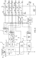
FIG. 4 is a schematic block diagram of an air data system interface circuit. -
FIG. 5 is a schematic block diagram showing the air data probe interface circuit shown inFIG. 4 with multiple air data systems. -
FIG. 1 is a perspective view of an aircraft showing several air data systems. Shown inFIG. 1 areaircraft 10,air data systems 12, andcontrol module 50.Aircraft 10 is an exemplary unmanned aerial vehicle (i. e., having no onboard pilot or air crew), being smaller in size and weight than a typical commercial or military aircraft. A number ofair data systems 12 are distributed onaircraft 10, each producing an electrical signal that is representative of a sensed pressure as will be described in more detail later inFIGS. 2A - 2E .Control module 50 provides centralized control of multipleair data systems 12, and will be described in greater detail later, inFIG. 3 . In some embodiments,aircraft 10 can be a manned aircraft, with non-limiting examples including private, commercial, and military aircraft. Any number ofair data systems 12 is within the scope of the present disclosure, and the variousair data systems 12 can be located anywhere onaircraft 10. Moreover, all type and sizes ofaircraft 10 are within the scope of the present disclosure. The following figures illustrate four exemplaryair data systems 12, which will be labeled as 12a, 12b, 12c, and 12d, described as follows. -
FIG. 2A is a perspective view of totalpressure data system 12a,FIG. 2B is a perspective view of a staticpressure data system 12b,FIG. 2C is a perspective view of a total airtemperature data system 12c, andFIG. 2D is a perspective view of angle ofattack data system 12d. Totalpressure data system 12a includestotal pressure probe 14a, and can be used for measuring a total pressure during flight ofaircraft 10. Staticpressure data system 12b includesstatic pressure probe 14b, and can be used for measuring a static pressure during flight ofaircraft 10. Total airtemperature data system 12c includes totalair temperature probe 14c, and can be used for measuring a total air temperature during flight ofaircraft 10. Angle ofattack data system 12d includes angle ofattack probe 14d, and can be used for measuring an angle of attack during flight ofaircraft 10. -
FIG. 2E is a perspective view of the bottom of totalpressure data system 12a shown inFIG. 2A , while also being representative of the bottoms of staticpressure data system 12b, total airtemperature data system 12c, and angle ofattack data system 12d. Shown inFIG. 2E areair data system 12, air datasystem instrument package 16, air datasystem signal connector 19, and air data system power connector 20. In the illustrated embodiment,air data system 12 can be totalpressure data system 12a, staticpressure data system 12b, total airtemperature data system 12c, or angle ofattack data system 12d. In other embodiments,air data system 12 can be configured to measure another environmental parameter onaircraft 10. Air datasystem instrument package 16 includes sensors and associated electronic circuitry (not shown) that are used to measure the particular environmental parameter for which the particularair data system 12 is configured to measure. Non-limiting examples of sensors include micromechanical piezoresistive pressure sensors for measuring pressure, and resistance temperature detectors for measuring temperature. A pressure sensor, for example, can be configured to measure absolute, gage, or differential pressure, depending on the particular environmental parameter being measured. An electrical heater (not shown inFIGS. 2A - 2E ) can be used to control ice accretion on an associated probe (e.g.,total pressure probe 14a,static pressure probe 14b, totalair temperature probe 14c, angle ofattack probe 14d), because ice accumulation can affect the ability of a particular sensor to accurately measure a particular environmental parameter. Air datasystem signal connector 19 provides an electrical connection for an associated cable (not shown) to connect air datasystem instrument package 16 to controlsystem 50, and will be described in greater detail later inFIG. 3 . Similarly, air data system power connector 20 provides an electrical connection for an associated cable (not shown) to connect air datasystem instrument package 16 to controlsystem 50, and will be described in greater detail later inFIG. 3 . In the illustrated embodiment, air data system power connector 20 provides electrical power for the heater, while electronics power is provided via air datasystem signal connector 19. In some embodiments, heater power and/or electronics power can be provided toair data system 12 via air datasystem signal connector 19 and/or air data system power connector 20. In other embodiments, a single electrical connector can be used on air datasystem instrument package 16. In yet other embodiments, three or more electrical connectors can be used on air datasystem instrument package 16. - Referring again to
FIGS. 2A - 2E , each of the variousair data systems 12 onaircraft 10 function as a self-contained instrument that receives electrical power and control signals fromcontrol system 50, and transmits electrical signals indicative of a sensed environmental parameter to controlsystem 50. Accordingly, totalpressure data system 12a can be referred to as a smart pitot system, staticpressure data system 12b can be referred to as a smart static system, total airtemperature data system 12c can be referred to as a smart total air temperature (TAT) system, and angle ofattack data system 12d can be referred to as a smart angle of attack (AOA) system. Moreover, the collection ofair data systems 12 in a particular embodiment, along withcontroller 50, can be referred to as a distributed electric air data module system, or as a distributed air data module system. -
FIG. 3 is a schematic block diagram of a distributed air data module system. Shown inFIG. 3 are distributed airdata module system 100, totalpressure data system 12a, staticpressure data system 12b, total airtemperature data system 12c, angle ofattack data system 12d, totalpressure data channel 18a, staticpressure data channel 18b, total airtemperature data channel 18c, angle ofattack data channel 18d,aircraft power supply 22,heater power line 24,equipment power line 26,heaters heater control circuits heater monitors pressure sensors air temperature element 40c, resolver/damper 40d,signal conditioners data transceivers control module 50, data in 86, and data out 88. Totalpressure data system 12a, staticpressure data system 12b, total airtemperature data system 12c, and angle ofattack data system 12d (i.e., air data systems 12) were described above in regard toFIGS. 2A - 2D , with each having associated data channel 18 (e.g., totalpressure data channel 18a, staticpressure data channel 18b, total airtemperature data channel 18c, angle ofattack data channel 18d) that provides electrical connectivity to controlsystem 50.Aircraft power supply 22 provides electrical heater power to eachair data system 12 viaheater power line 24. Accordingly, in the illustrated embodiment, eachdata channel 18 is electrically connected to a respectiveair data system 12 at air datasystem signal connector 19, and eachair data system 12 receives an associatedheater power line 24 at air data system power connector 20, as shown inFIG. 2E . Each respectiveair data system heater heater control circuit air data system pressure data system 12a (i.e., smart pitot system) and staticpressure data system 12b (i.e., smart static system) each includepressure sensor data system 12c (i.e., smart TAT system) includesTAT element 40c. Angle of attack (AOA)data system 12d (i.e., smart AOA system) includes resolver/damper 40d. - Referring again to
FIG. 3 , eachair data system signal conditioner FIG. 3 ) provided by the associated sensor 40 (i.e.,pressure sensors air temperature element 40c, and resolver/damper 40d, respectively). In the illustrated embodiment,signal conditioners Sensor ADCs sensor 40. In the illustrated embodiment,sensor ADCs more sensor ADCs more sensor ADCs sensor ADC air data system data transceiver respective data channel Control module 50 provides a centralized control function forair data systems FIGS. 4 - 5 . Other functions performed bycontrol module 50 include providing power conditioning, electrical isolation from other onboard systems, and electronics power supply to the variousair data systems 12, providing processing and storage of data, and providing a buffered data input/output interface (not shown inFIG. 3 ) to other systems (e.g., avionics system)onboard aircraft 10. Data in 86 and data out 88 provide data communication lines for data input to controlsystem 50, and for data output fromcontrol system 50, respectively. Accordingly, data in 86 and data out 88 provide for data communications to and from distributed airdata module system 100, respectively. Data in 86 and/or data out 88 can also be referred to as data channels, or as data busses. Data communications to and from control system 50 (i.e., distributed air data module system 100) will be described in greater detail later, inFIG. 5 . - In the exemplary embodiment illustrated in
FIG. 3 , fourair data systems pressure data system 12a, staticpressure data system 12b, total airtemperature data system 12c, and angle ofattack data system 12d, respectively). In some embodiments, two or more of each particularair data system air data systems air data systems air data systems 12 used in a particular embodiment, allair data systems 12 that are included in a particular distributed airdata module system 100 communicate via an associateddata channel 18 withcontrol system 50. Accordingly, any particular configuration ofair data systems 12 is within the scope of the present disclosure. -
FIG. 4 is a schematic block diagram of an air data system interface circuit. Shown inFIG. 4 are isolated data channel 18',aircraft power supply 22,heater power line 24,equipment power lines 26, 26',heater 30,heater control circuit 32,heater command signal 33, heater monitor 34, heatercurrent sensor 35,heater control feedback 36, heater analog to digital converter (ADC) 37,sensor 40,reference 42,sensor output signal 43, signal conditioner 44, signal conditioner output signal 45,sensor ADC 46, de-multiplexer (DEMUX) 54,isolation module 60,line buffers clock signal 66b, serial data in 66c,heater command 66d,address lines electronics power supply 68, andfault storage 74. Isolated data channel 18' contains a number of individual data lines (e.g., serial data out 66a,clock signal 66b, serial data in 66c,heater command 66d,address lines control module 50. However, isolated data channel 18' conveys the same signals as provided on data channel 18 (i.e., 18a, 18b, 18c, 18d) as described above in regard toFIG. 3 . The descriptions ofaircraft power supply 22,heater power line 24, andequipment power line 26, are substantially as were provided above in regard toFIG. 3 .Heater 30 is an electrical heater that receives electrical power fromheater power line 24, thereby producing heat to control ice accretion of the associated probe (e.g.,total pressure probe 14a,static pressure probe 14b, totalair temperature probe 14c, angle ofattack probe 14d) of a particularair data system 12.Heater control circuit 32 receivesheater command signal 33, thereby controlling the flow of electrical current throughheater 30 by alternately making and breaking a path for current flow. Heater monitor 34 senses the flow of electrical current throughheater 30 by detecting an electrical signal that is produced by heatercurrent sensor 35. In the illustrated embodiment, heatercurrent sensor 35 is a resistor that develops a voltage potential when heater current flows in series through heatercurrent sensor 35.Heater control feedback 36 directsheater control circuit 32 in maintaining the desired temperature ofheater 30.Heater ADC 37 produces a digital signal that is representative of the flow of electrical current throughheater 30.Heater ADC 37 can be referred to as a chip, and transmits the so-produced digital signal when invoked by a chip select (CS) signal, as will be described. -
Sensor 40 represents a particular sensor (e.g.,pressure sensor air temperature element 40c, resolver/damper 40d) in the associated air data system 12 (e.g., totalpressure data system 12a, staticpressure data system 12b, total airtemperature data system 12c, angle ofattack data system 12d). It is to be appreciated thatFIG. 4 illustrates air data system interface circuit 110 with regard to a particularair data system 12, with the embodiment that was illustrated inFIG. 3 including fourair data systems 12.Reference 42 provides reference values that are used bysensor 40, and can also be referred to as a sensor reference. In the illustrated embodiment,reference 42 provides calibration and linearity factors that are applied tosensor 40 to improve the accuracy in measuring a particular environmental parameter.Sensor 40 producessensor output signal 43 which is received by signal conditioner 44 and provided as signal conditioner output signal 45. The descriptions ofsignal ADC 46 is as provided above in regard toFIG. 3 .Signal ADC 46 transmits the digitized representation ofsensor output signal 43 when invoked by a chip select (CS) line, as will be described. Signal ADC can also be referred to as a chip. -
DEMUX 54 receives a chip select (CS) address viaaddress lines heater ADC 37, data transceiver 48, fault storage 74). In the illustrated embodiment there are twoaddress lines FIG. 4 , the twoaddress lines heater ADC 37,sensor ADC 46, and fault storage 74). In other embodiments, there can be three ormore address lines - Referring again to
FIG. 4 ,isolation module 60 provides electrical isolation in air data system interface circuit 110 by providing electromagnetic interference (EMI) suppression, surge and impulse suppression, noise filtering, and the like.Isolation module 60 also includesline buffers clock signal 66b, serial data in 66c,heater command 66d,address lines air data system 12. In an exemplary embodiment, line buffers 62a - 62f each include an optical isolator (i.e., opto-isolator) that transmits a data signal while electrically isolating therespective data line 66a - 66f acrossisolation module 60. In some embodiments, one or more line buffers 62a - 62f can be a different type of line buffer, with non-limiting examples including single-input line buffers and/or non-optical line buffers. Referring again toFIG. 4 ,isolation module 60 can also include electrical surge and isolation clamping circuits, EMI and/or radio frequency (RF) filters, low-pass and/or band-pass filters, and other electrical isolation components. In other embodiments, isolation module 60 (i.e., including line buffers 62) can utilize other means of providing electrical isolation. Accordingly,isolation module 60 provides protection against electrical and electromagnetic interference that can occur from sources onboardaircraft 10 and/or external toaircraft 10. Non-limiting examples of onboard interference sources include motors, actuators, relays, and radio transceivers. Non-limiting examples of external interference include static charges, lightning strikes, induced voltages from radio and/or radar transmissions, and electromagnetic pulses (EMP). - Referring again to
FIG. 4 ,fault storage 74 stores (i.e., holds) data within distributed airdata module system 100, with non-limiting examples including fault values and locations, sensor coefficients, and the like. In the illustrated embodiment,fault storage 74 is non-volatile storage, with a non-limiting example being erasable programmable read-only memory (EPROM).Fault storage 74 can also be referred to as a chip, and can receive data input and/or provide data output as enabled by a by a chip select line fromDEMUX 54, in which addresslines storage 74.Fault storage 74 can also be referred to as computer-readable memory, or as a fault storage module. Data transfer within a particularair data system 12 is performed serially. In an exemplary embodiment, a serial peripheral interface (SPI) over an RS-422 physical layer can be used. In other embodiments, other data exchange protocols can be used. Individual data lines 66 provide bi-directional data communication within distributed airdata module system 100, thereby providing data communication betweencontrol module 50 and any particularair data system 12. Serial data out 66a transmits data from the selected chip (e.g.,heater ADC 37, data transceiver 48, fault storage 74) depending on the particular chip select line that is enabled.Clock signal 66b provides a system clock signal to the various chips (e.g.,heater ADC 37, data transceiver 48, fault storage 74). Serial data in 66c provides data to a selected chip (e.g.,heater ADC 37, data transceiver 48, fault storage 74) depending on the particular chip select line that is enabled.Heater command 66d providesheater command signal 33, as described above in regard toFIG. 3 . -
FIG. 5 is a schematic block diagram showing distributed airdata module system 100. Shown inFIG. 5 are totalpressure data system 12a (i.e., smart pitot system), staticpressure data system 12b (i.e., smart static system), total airtemperature data system 12c (i.e., smart TAT system), angle ofattack data system 12d (i.e., smart AOA system), isolated equipment power line 26',control system 50, communications toremote sensors module 60, serial data out 66a,clock signal 66b, serial data in 66c,heater command 66d,address lines processor 70,memory 72,fault storage 74,data interface module 80,isolation boundary 81,data management module 82,data communications drivers 84, Data in 86, Data out 88, discrete input/output (I/O) module 90, electromagnetic interference (EMI) andtransient protection module 92, and distributed airdata module system 100. As used in the present disclosure, "communications" can be abbreviated as "comms". The descriptions of totalpressure data system 12a, staticpressure data system 12b, total airtemperature data system 12c, angle ofattack data system 12d, isolated equipment power line 26',control system 50, serial data out 66a,clock signal 66b, serial data in 66c,heater command 66d,address lines electronics power supply 68, andfault storage 74 are as provided above in regard toFIGS. 3 - 4 . Communications toremote sensors module 60 provides communications fromcontrol system 50 to totalpressure data system 12a, staticpressure data system 12b, total airtemperature data system 12c, and angle ofattack data system 12d. Collectively, serial data out 66a,clock signal 66b, serial data in 66c,heater command 66d, andaddress lines Processor 70 communicates data viadata lines 66 to various air data systems 12 (e.g., totalpressure data system 12a, staticpressure data system 12b, total airtemperature data system 12c, angle ofattack data system 12d) throughisolation module 60 as described above in regard toFIG. 4 . - Processor provides
clock signal 66b and signals foraddress lines data module system 100, and in turn driving data flow throughout distributed airdata module system 100.Processor 70 is configured to implement functionality and/or process instructions for execution within controller 50 (not labeled inFIG. 5 ). Examples ofprocessor 70 can include any one or more of a microprocessor, a controller, a digital signal processor (DSP), an application specific integrated circuit (ASIC), a field-programmable gate array (FPGA), or other equivalent discrete or integrated logic circuitry.Processor 70 can receive process instructions that are stored inmemory 72. Examples ofmemory 72 can include random access memories (RAM), dynamic random access memories (DRAM), static random access memories (SRAM), and other forms of digital storage media. Accordingly,memory 72 can be referred to as computer-readable memory.Processor 70 provides bi-directional data communication viadata interface module 80.Data interface module 80 provides two-way data communications between distributed airdata module system 100 and other systems.Data interface module 80 includesdata management module 82 anddata communications drivers 84 for communicating with other systems (i.e., avionics)onboard aircraft 10.Data communications drivers 84 receive input data via data in 86 and transmit output data via data out 88.Data communications drivers 84 include optical isolators (i.e., opto-isolators) that transmit data signals while electrically isolating individual data lines, thereby helpingform isolation boundary 81 betweendata management module 82 anddata communications drivers 84. Isolation boundary also provides electrical isolation withinelectronics power supply 68, as described above in regard toFIG. 4 . In an exemplary embodiment, distributed airdata module system 100 and associatedaircraft 10 can use the ARINC-429 technical standard. In other embodiments, any other data communication protocol (i.e., technical standard) can be used by distributed airdata module system 100 and/oraircraft 10, with non-limiting examples including RS-422, RS-485, MIL-STD-1553, controller area network (CAN). In yet other embodiments, other data communications protocols can be used, including a proprietary and/or or airframe-unique data communications protocol. - Referring again to
FIG. 5 , data communication to and fromprocessor 70 also occurs via discrete input/output (I/O) module 90. In some embodiments, data transmitted via discrete I/O module 90 can be similar to data transmitted viadata interface module 80. In other embodiments, other data can be provided via discrete I/O module 90, with non-limiting examples including environmental liquid water content (LWC) from ice-detection systems, heater command signals, and heater location signals. EMI andtransient protection module 92 provides electrical isolation and has a description that is substantially similar to that provided forisolation module 60 above in regard toFIG. 4 . In having EMI andtransient protection module 92, as shown inFIG. 5 . By electrically isolating components that are vulnerable to EMI from various interfaces onaircraft 10, the cumulative number of individual EMI, surge, and transient isolation devices is reduced, thereby reducing the overall size, weight, and cost associated with EMI, surge, and transient isolation within distributed airdata module system 100. - The following are non-exclusive descriptions of possible embodiments of the present invention.
- A distributed air data module system, comprising: a plurality of air data systems, each comprising: a sensor, configured to sense an air data parameter and to provide a sensor output signal that is indicative of the sensed air data parameter; and a sensor analog-to-digital converter (ADC), configured to produce a digital air data parameter signal that is representative of the sensor output signal; wherein each of the plurality of air data systems has an associated air data system address code; and a control module, communicatively connected to each of the plurality of air data systems via a data channel, the control module configured to: generate a selected air data system address code corresponding to a selected one of the plurality of air data systems; receive, via the data channel, the digital air data parameter signal associated with the selected one of the plurality of air data systems; and transmit, via an aircraft data bus, the digital air data parameter signal.
- The distributed air data module system of the preceding paragraph can optionally include, additionally and/or alternatively, any one or more of the following features, configurations and/or additional components:
- A further embodiment of the foregoing distributed air data module system, wherein: the sensor is a total pressure sensor that is configured to sense a total pressure; and the air data parameter signal is representative of the total pressure.
- A further embodiment of the foregoing distributed air data module system, wherein: the sensor is a static pressure sensor that is configured to sense a static pressure; and the air data parameter signal is representative of the static pressure.
- A further embodiment of the foregoing distributed air data module system, wherein: the sensor is a total air temperature sensor that is configured to sense a total air temperature; and the air data parameter signal is representative of the total air temperature.
- A further embodiment of the foregoing distributed air data module system, wherein: the sensor is an angle of attack sensor that is configured to sense an angle of attack; and the air data parameter signal is representative of the angle of attack.
- A further embodiment of the foregoing distributed air data module system, wherein each of the air data systems further comprises a signal conditioner that is configured to amplify and/or filter the sensor output signal.
- A further embodiment of the foregoing distributed air data module system, wherein each digital air data parameter signal comprises at least 12 bits.
- A further embodiment of the foregoing distributed air data module system, wherein the air data sensor address code comprises two or more bits.
- A further embodiment of the foregoing distributed air data module system, wherein each of the air data systems further comprises: a heater, configured to: receive heater electrical power; and convert the heater electrical power into heat, thereby melting ice; a heater control circuit, configured to control the heater electrical power in response to a heater command signal from the control module; a heater monitor circuit, configured to monitor an electrical current flowing through the heater; and a heater analog-to-digital converter (ADC), configured to: produce a digital heater current signal that is representative of the electrical current flowing through the heater; and transmit the digital heater current signal via a serial data output line to the control module when commanded by a chip select signal.
- A further embodiment of the foregoing distributed air data module system, wherein each of the air data systems further comprises a fault storage device, configured to: store system fault data representative of a fault in the particular air data system; and transmit the system fault data via a serial data output line to the control module when commanded by a chip select signal.
- A further embodiment of the foregoing distributed air data module system, wherein each of the sensor ADCs is further configured to transmit the digital air data parameter signal via a serial data output line when commanded by a chip select signal.
- A further embodiment of the foregoing distributed air data module system, wherein each of the air data systems further comprises a de-multiplexer, configured to: receive a chip select address via two or more address lines; and based on the received chip select address, generate a chip enable signal corresponding to a selected chip; wherein the selected chip is selected from the group consisting of a heater ADC, the sensor ADC, and a fault storage.
- A further embodiment of the foregoing distributed air data module system, further comprising an electromagnetic interference (EMI) protection interface configured to provide EMI isolation between the plurality of air data systems and the control module.
- A further embodiment of the foregoing distributed air data module system, further comprising a plurality of data channels, each corresponding to an associated one of the plurality of air data systems, wherein: each of the plurality of data channels comprises: a serial data output line, configured to transmit serial data from the associated air data system; a clock signal line, configured to provide a clock signal to the associated air data system; a serial data input line, configured to transmit serial data to the associated air data system; a heater command line, configured to transmit a heater command signal to the associated air data system; and two or more address lines, configured to together transmit a chip select address; and each of the plurality of data channels communicatively connects the associated air data system to the control module.
- A further embodiment of the foregoing distributed air data module system, further comprising an isolation module configured to provide electrical isolation between the control module and one or more of the plurality of air data systems, the isolation module comprising one or more optical isolators.
- A further embodiment of the foregoing distributed air data module system, wherein the aircraft data bus comprises an ARINC-429 technical standard.
- A further embodiment of the foregoing distributed air data module system, further comprising a discrete input/output (I/O) module, configured to transfer data from the control module to an external system.
- A method of using a distributed air data module system, the distributed air data module system comprising a plurality of air data systems and a control module communicatively connected to each of the plurality of air data systems via a data channel, each of the plurality of air data systems having an associated air data system address code, each of the plurality of air data systems comprising a sensor and a sensor analog-to-digital converter (ADC), each sensor configured to sense an air data parameter and to provide a sensor output signal that is indicative of the sensed air data parameter, and the sensor ADC configured to produce a digital air data parameter signal that is representative of the sensor output signal, the method comprising: producing, by each of the plurality of sensors, a corresponding sensor output signal; producing, by each of the sensor ADCs, a corresponding digital air data parameter signal; generating, by the control module, a selected air data system address code corresponding to a selected air data system; receiving, via the data channel, the digital air data parameter signal associated with the selected air data system based on the generated air data sensor address code; and transmitting, via an aircraft data bus, the digital air data parameter signal.
- The method of the preceding paragraph can optionally include, additionally and/or alternatively, any one or more of the following features, configurations and/or additional components:
- A further embodiment of the foregoing method, wherein each of the sensor ADCs is further configured to transmit the digital air data parameter signal when commanded by a chip select signal.
- A further embodiment of the foregoing method, wherein each of the air data systems further comprises de-multiplexer, configured to: receive a chip select address via two or more address lines; and based on the received chip select address, generate a chip enable signal corresponding to a selected chip; wherein the selected chip is selected from the group consisting of heater ADC, sensor ADC, and fault storage.
- While the invention has been described with reference to an exemplary embodiment(s), it will be understood by those skilled in the art that various changes may be made and equivalents may be substituted for elements thereof without departing from the scope of the invention. In addition, many modifications may be made to adapt a particular situation or material to the teachings of the invention without departing from the essential scope thereof. Therefore, it is intended that the invention not be limited to the particular embodiment(s) disclosed, but that the invention will include all embodiments falling within the scope of the appended claims.
Claims (15)
- A distributed air data module system, comprising:a plurality of air data systems (12), each comprising:a sensor, configured to sense an air data parameter and to provide a sensor output signal that is indicative of the sensed air data parameter; anda sensor analog-to-digital converter (ADC), configured to produce a digital air data parameter signal that is representative of the sensor output signal;wherein each of the plurality of air data systems has an associated air data system address code; anda control module (50), communicatively connected to each of the plurality of air data systems via a data channel, the control module configured to:generate a selected air data system address code corresponding to a selected one of the plurality of air data systems;receive, via the data channel, the digital air data parameter signal associated with the selected one of the plurality of air data systems; andtransmit, via an aircraft data bus, the digital air data parameter signal.
- The distributed air data module system of claim 1, wherein:the sensor is a total pressure sensor that is configured to sense a total pressure; andthe air data parameter signal is representative of the total pressure; orwherein:the sensor is a static pressure sensor that is configured to sense a static pressure; andthe air data parameter signal is representative of the static pressure; orwherein:the sensor is a total air temperature sensor that is configured to sense a total air temperature; andthe air data parameter signal is representative of the total air temperature; orwherein:the sensor is an angle of attack sensor that is configured to sense an angle of attack; andthe air data parameter signal is representative of the angle of attack.
- The distributed air data module system of claim 1 or 2, wherein each of the air data systems further comprises a signal conditioner that is configured to amplify and/or filter the sensor output signal.
- The distributed air data module system of any preceding claim, wherein each digital air data parameter signal comprises at least 12 bits.
- The distributed air data module system of any preceding claim, wherein the air data sensor address code comprises two or more bits.
- The distributed air data module system of any preceding claim, wherein each of the air data systems further comprises:a heater, configured to:receive heater electrical power; andconvert the heater electrical power into heat, thereby melting ice;a heater control circuit, configured to control the heater electrical power in response to a heater command signal from the control module;a heater monitor circuit, configured to monitor an electrical current flowing through the heater; anda heater analog-to-digital converter (ADC), configured to:produce a digital heater current signal that is representative of the electrical current flowing through the heater; andtransmit the digital heater current signal via a serial data output line to the control module when commanded by a chip select signal.
- The distributed air data module system of any preceding claim, wherein each of the air data systems further comprises a fault storage device, configured to:store system fault data representative of a fault in the particular air data system; andtransmit the system fault data via a serial data output line to the control module when commanded by a chip select signal.
- The distributed air data module system of any preceding claim, wherein each of the sensor ADCs is further configured to transmit the digital air data parameter signal via a serial data output line when commanded by a chip select signal.
- The distributed air data module system of any preceding claim, wherein each of the air data systems further comprises a de-multiplexer, configured to:receive a chip select address via two or more address lines; andbased on the received chip select address, generate a chip enable signal corresponding to a selected chip;wherein the selected chip is selected from the group consisting of a heater ADC, the sensor ADC, and a fault storage.
- The distributed air data module system of any preceding claim, further comprising an electromagnetic interference (EMI) protection interface configured to provide EMI isolation between the plurality of air data systems and the control module.
- The distributed air data module system of any preceding claim, further comprising a plurality of data channels, each corresponding to an associated one of the plurality of air data systems, wherein:each of the plurality of data channels comprises:a serial data output line, configured to transmit serial data from the associated air data system;a clock signal line, configured to provide a clock signal to the associated air data system;a serial data input line, configured to transmit serial data to the associated air data system;a heater command line, configured to transmit a heater command signal to the associated air data system; andtwo or more address lines, configured to together transmit a chip select address; andeach of the plurality of data channels communicatively connects the associated air data system to the control module; and preferablyfurther comprising an isolation module configured to provide electrical isolation between the control module and one or more of the plurality of air data systems, the isolation module comprising one or more optical isolators.
- The distributed air data module system of any preceding claim, wherein the aircraft data bus comprises an ARINC-429 technical standard; and/or further comprising a discrete input/output (I/O) module, configured to transfer data from the control module to an external system.
- A method of using a distributed air data module system, the distributed air data module system comprising a plurality of air data systems and a control module communicatively connected to each of the plurality of air data systems via a data channel, each of the plurality of air data systems having an associated air data system address code, each of the plurality of air data systems comprising a sensor and a sensor analog-to-digital converter (ADC), each sensor configured to sense an air data parameter and to provide a sensor output signal that is indicative of the sensed air data parameter, and the sensor ADC configured to produce a digital air data parameter signal that is representative of the sensor output signal, the method comprising:producing, by each of the plurality of sensors, a corresponding sensor output signal;producing, by each of the sensor ADCs, a corresponding digital air data parameter signal;generating, by the control module, a selected air data system address code corresponding to a selected air data system;receiving, via the data channel, the digital air data parameter signal associated with the selected air data system based on the generated air data sensor address code; andtransmitting, via an aircraft data bus, the digital air data parameter signal.
- The method of claim 13, wherein each of the sensor ADCs is further configured to transmit the digital air data parameter signal when commanded by a chip select signal.
- The method of claims 13 or 14, wherein each of the air data systems further comprises de-multiplexer, configured to:receive a chip select address via two or more address lines; andbased on the received chip select address, generate a chip enable signal corresponding to a selected chip;wherein the selected chip is selected from the group consisting of heater ADC, sensor ADC, and fault storage.
Applications Claiming Priority (1)
| Application Number | Priority Date | Filing Date | Title |
|---|---|---|---|
| US16/533,025 US11627014B2 (en) | 2019-08-06 | 2019-08-06 | Distributed electric air data module system |
Publications (1)
| Publication Number | Publication Date |
|---|---|
| EP3772857A1 true EP3772857A1 (en) | 2021-02-10 |
Family
ID=68808036
Family Applications (1)
| Application Number | Title | Priority Date | Filing Date |
|---|---|---|---|
| EP19213918.6A Pending EP3772857A1 (en) | 2019-08-06 | 2019-12-05 | Distributed electric air data module system |
Country Status (4)
| Country | Link |
|---|---|
| US (1) | US11627014B2 (en) |
| EP (1) | EP3772857A1 (en) |
| BR (1) | BR102019026522A2 (en) |
| CA (1) | CA3063943A1 (en) |
Families Citing this family (2)
| Publication number | Priority date | Publication date | Assignee | Title |
|---|---|---|---|---|
| US10142196B1 (en) * | 2016-04-15 | 2018-11-27 | Senseware, Inc. | System, method, and apparatus for bridge interface communication |
| CN114152402B (en) * | 2022-02-07 | 2022-05-31 | 中国空气动力研究与发展中心低速空气动力研究所 | Wind tunnel test water content measuring device |
Citations (2)
| Publication number | Priority date | Publication date | Assignee | Title |
|---|---|---|---|---|
| EP2098927A1 (en) * | 2006-12-18 | 2009-09-09 | JTEKT Corporation | Plc dispersion control system |
| EP3333577A1 (en) * | 2016-12-09 | 2018-06-13 | Rosemount Aerospace Inc. | Triple-redundant air data system architecture |
Family Cites Families (14)
| Publication number | Priority date | Publication date | Assignee | Title |
|---|---|---|---|---|
| US6250149B1 (en) * | 1999-04-08 | 2001-06-26 | The Boeing Company | System and method for generating aircraft flight data using a flush-mounted air data system |
| US6543298B2 (en) | 2001-07-13 | 2003-04-08 | Rosemount Aerospace Inc. | Method of reducing total temperature errors and multi-function probe implementing same |
| US6761057B2 (en) * | 2001-09-13 | 2004-07-13 | Rosemount Aerospace Inc. | Error detection and fault isolation for multi-function air data probes and systems |
| US6668640B1 (en) | 2002-08-12 | 2003-12-30 | Rosemount Aerospace Inc. | Dual-channel electronic multi-function probes and methods for realizing dissimilar and independent air data outputs |
| US7213454B2 (en) | 2005-04-06 | 2007-05-08 | Rosemount Aerospace Inc. | Method and apparatus for obtaining improved accuracy and range for air data parameters inferred from independent measurements of interdependent pressures |
| US7363809B2 (en) * | 2005-07-29 | 2008-04-29 | Honeywell International Inc. | Methods and systems for providing air data parameters using mass flow and pressure sensors |
| JP2010513939A (en) | 2006-12-19 | 2010-04-30 | ローズマウント・エアロスペース・インコーポレーテツド | Integrated global atmospheric temperature probe and electronics |
| US8620495B2 (en) * | 2006-12-19 | 2013-12-31 | Rosemount Aerospace Inc. | Air data stall protection system |
| US8527233B2 (en) | 2010-09-27 | 2013-09-03 | The Boeing Company | Airspeed sensing system for an aircraft |
| US10502594B2 (en) * | 2013-04-29 | 2019-12-10 | Emerson Electric (Us) Holding Corporation (Chile) Limitada | Dynamic transducer with digital output and method for use |
| US9841304B2 (en) | 2015-04-17 | 2017-12-12 | Rosemount Aerospace Inc. | Air data system |
| CN105953816A (en) | 2016-04-28 | 2016-09-21 | 江西洪都航空工业集团有限责任公司 | Distributed atmosphere data system |
| US10585698B2 (en) * | 2017-11-10 | 2020-03-10 | Salesforce.Com, Inc. | Template-driven multi-tenant workflow processing |
| US11582304B2 (en) * | 2019-12-20 | 2023-02-14 | Simmonds Precision Products, Inc. | Distributed sensing processing systems |
-
2019
- 2019-08-06 US US16/533,025 patent/US11627014B2/en active Active
- 2019-12-04 CA CA3063943A patent/CA3063943A1/en active Pending
- 2019-12-05 EP EP19213918.6A patent/EP3772857A1/en active Pending
- 2019-12-13 BR BR102019026522-1A patent/BR102019026522A2/en unknown
Patent Citations (2)
| Publication number | Priority date | Publication date | Assignee | Title |
|---|---|---|---|---|
| EP2098927A1 (en) * | 2006-12-18 | 2009-09-09 | JTEKT Corporation | Plc dispersion control system |
| EP3333577A1 (en) * | 2016-12-09 | 2018-06-13 | Rosemount Aerospace Inc. | Triple-redundant air data system architecture |
Also Published As
| Publication number | Publication date |
|---|---|
| US11627014B2 (en) | 2023-04-11 |
| CA3063943A1 (en) | 2021-02-06 |
| BR102019026522A2 (en) | 2021-02-17 |
| US20210044447A1 (en) | 2021-02-11 |
Similar Documents
| Publication | Publication Date | Title |
|---|---|---|
| EP2951707B1 (en) | Programmable interface circuit for coupling field devices to process controllers | |
| US11627014B2 (en) | Distributed electric air data module system | |
| JPH0965441A (en) | Low impedance intrinsically safe explosion-proof barrier | |
| EP0384259A2 (en) | Loop communication network | |
| GB2520330A (en) | Ultrasonic airspeed and direction sensor system | |
| US20140203147A1 (en) | Tip with nozzle load sensing and wireless communication functionality for refueling boom | |
| EP3333577B1 (en) | Triple-redundant air data system architecture | |
| EP3462141B1 (en) | Integral fluid measurement system | |
| US6252691B1 (en) | Intrasatellite wireless communication | |
| US9380648B2 (en) | Heating system for an aircraft or spacecraft | |
| US20100254465A1 (en) | Apparatus for transmission of electrical energy and information | |
| CA3021854C (en) | Address allocation to psus, service arrangement and passenger cabin | |
| US8633831B2 (en) | Single-wire telemetry and command | |
| EP3457176A1 (en) | Lidar air data system with decoupled lines of sight | |
| KR20050095329A (en) | System for on-board decentralized data acquisition with the star network, the method thereof | |
| WO1997049017A1 (en) | Circuit enabling external devices to communicate with central/decentralised data processing system by means of a bus | |
| EP2827507B1 (en) | Direct current signal transmission system | |
| US12153067B2 (en) | Measuring arrangement | |
| US8466809B2 (en) | System comprising two combined instruments mounted on board an aircraft and method implementing the system | |
| KR101629250B1 (en) | Temperature monitoring device of switchgear attached type separated FND | |
| CN101729330B (en) | High-precision AD conversion circuit and working method thereof | |
| CN108163216A (en) | A kind of low cost avionics system | |
| EP3985400B1 (en) | Inline sensor assembly to monitor air data probe heater | |
| US12627136B2 (en) | Electrical device with indirect lightning protection, attitude and heading reference system, and aircraft | |
| US11740109B2 (en) | Digital air data systems and methods |
Legal Events
| Date | Code | Title | Description |
|---|---|---|---|
| PUAI | Public reference made under article 153(3) epc to a published international application that has entered the european phase |
Free format text: ORIGINAL CODE: 0009012 |
|
| STAA | Information on the status of an ep patent application or granted ep patent |
Free format text: STATUS: THE APPLICATION HAS BEEN PUBLISHED |
|
| AK | Designated contracting states |
Kind code of ref document: A1 Designated state(s): AL AT BE BG CH CY CZ DE DK EE ES FI FR GB GR HR HU IE IS IT LI LT LU LV MC MK MT NL NO PL PT RO RS SE SI SK SM TR |
|
| AX | Request for extension of the european patent |
Extension state: BA ME |
|
| STAA | Information on the status of an ep patent application or granted ep patent |
Free format text: STATUS: REQUEST FOR EXAMINATION WAS MADE |
|
| 17P | Request for examination filed |
Effective date: 20210809 |
|
| RBV | Designated contracting states (corrected) |
Designated state(s): AL AT BE BG CH CY CZ DE DK EE ES FI FR GB GR HR HU IE IS IT LI LT LU LV MC MK MT NL NO PL PT RO RS SE SI SK SM TR |
|
| STAA | Information on the status of an ep patent application or granted ep patent |
Free format text: STATUS: EXAMINATION IS IN PROGRESS |
|
| 17Q | First examination report despatched |
Effective date: 20230607 |