EP3772769A1 - Battery pack including a high- and low-current discharge terminals - Google Patents
Battery pack including a high- and low-current discharge terminals Download PDFInfo
- Publication number
- EP3772769A1 EP3772769A1 EP20190324.2A EP20190324A EP3772769A1 EP 3772769 A1 EP3772769 A1 EP 3772769A1 EP 20190324 A EP20190324 A EP 20190324A EP 3772769 A1 EP3772769 A1 EP 3772769A1
- Authority
- EP
- European Patent Office
- Prior art keywords
- battery pack
- terminal
- battery
- current
- limiting circuit
- Prior art date
- Legal status (The legal status is an assumption and is not a legal conclusion. Google has not performed a legal analysis and makes no representation as to the accuracy of the status listed.)
- Pending
Links
Images





Classifications
-
- H—ELECTRICITY
- H02—GENERATION; CONVERSION OR DISTRIBUTION OF ELECTRIC POWER
- H02J—ELECTRIC POWER NETWORKS; CIRCUIT ARRANGEMENTS OR SYSTEMS FOR SUPPLYING OR DISTRIBUTING ELECTRIC POWER; SYSTEMS FOR STORING ELECTRIC ENERGY
- H02J7/00—Circuit arrangements for charging or discharging batteries or for supplying loads from batteries
- H02J7/60—Circuit arrangements for charging or discharging batteries or for supplying loads from batteries including safety or protection arrangements
- H02J7/663—Circuit arrangements for charging or discharging batteries or for supplying loads from batteries including safety or protection arrangements using battery or load disconnect circuits
-
- B—PERFORMING OPERATIONS; TRANSPORTING
- B25—HAND TOOLS; PORTABLE POWER-DRIVEN TOOLS; MANIPULATORS
- B25F—COMBINATION OR MULTI-PURPOSE TOOLS NOT OTHERWISE PROVIDED FOR; DETAILS OR COMPONENTS OF PORTABLE POWER-DRIVEN TOOLS NOT PARTICULARLY RELATED TO THE OPERATIONS PERFORMED AND NOT OTHERWISE PROVIDED FOR
- B25F5/00—Details or components of portable power-driven tools not particularly related to the operations performed and not otherwise provided for
- B25F5/02—Construction of casings, bodies or handles
-
- H—ELECTRICITY
- H01—ELECTRIC ELEMENTS
- H01M—PROCESSES OR MEANS, e.g. BATTERIES, FOR THE DIRECT CONVERSION OF CHEMICAL ENERGY INTO ELECTRICAL ENERGY
- H01M10/00—Secondary cells; Manufacture thereof
- H01M10/05—Accumulators with non-aqueous electrolyte
- H01M10/058—Construction or manufacture
-
- H—ELECTRICITY
- H01—ELECTRIC ELEMENTS
- H01M—PROCESSES OR MEANS, e.g. BATTERIES, FOR THE DIRECT CONVERSION OF CHEMICAL ENERGY INTO ELECTRICAL ENERGY
- H01M10/00—Secondary cells; Manufacture thereof
- H01M10/42—Methods or arrangements for servicing or maintenance of secondary cells or secondary half-cells
- H01M10/4207—Methods or arrangements for servicing or maintenance of secondary cells or secondary half-cells for several batteries or cells simultaneously or sequentially
-
- H—ELECTRICITY
- H01—ELECTRIC ELEMENTS
- H01M—PROCESSES OR MEANS, e.g. BATTERIES, FOR THE DIRECT CONVERSION OF CHEMICAL ENERGY INTO ELECTRICAL ENERGY
- H01M10/00—Secondary cells; Manufacture thereof
- H01M10/42—Methods or arrangements for servicing or maintenance of secondary cells or secondary half-cells
- H01M10/425—Structural combination with electronic components, e.g. electronic circuits integrated to the outside of the casing
-
- H—ELECTRICITY
- H01—ELECTRIC ELEMENTS
- H01M—PROCESSES OR MEANS, e.g. BATTERIES, FOR THE DIRECT CONVERSION OF CHEMICAL ENERGY INTO ELECTRICAL ENERGY
- H01M10/00—Secondary cells; Manufacture thereof
- H01M10/42—Methods or arrangements for servicing or maintenance of secondary cells or secondary half-cells
- H01M10/44—Methods for charging or discharging
- H01M10/441—Methods for charging or discharging for several batteries or cells simultaneously or sequentially
-
- H—ELECTRICITY
- H01—ELECTRIC ELEMENTS
- H01M—PROCESSES OR MEANS, e.g. BATTERIES, FOR THE DIRECT CONVERSION OF CHEMICAL ENERGY INTO ELECTRICAL ENERGY
- H01M50/00—Constructional details or processes of manufacture of the non-active parts of electrochemical cells other than fuel cells, e.g. hybrid cells
- H01M50/20—Mountings; Secondary casings or frames; Racks, modules or packs; Suspension devices; Shock absorbers; Transport or carrying devices; Holders
- H01M50/204—Racks, modules or packs for multiple batteries or multiple cells
- H01M50/207—Racks, modules or packs for multiple batteries or multiple cells characterised by their shape
- H01M50/213—Racks, modules or packs for multiple batteries or multiple cells characterised by their shape adapted for cells having curved cross-section, e.g. round or elliptic
-
- H—ELECTRICITY
- H01—ELECTRIC ELEMENTS
- H01M—PROCESSES OR MEANS, e.g. BATTERIES, FOR THE DIRECT CONVERSION OF CHEMICAL ENERGY INTO ELECTRICAL ENERGY
- H01M50/00—Constructional details or processes of manufacture of the non-active parts of electrochemical cells other than fuel cells, e.g. hybrid cells
- H01M50/20—Mountings; Secondary casings or frames; Racks, modules or packs; Suspension devices; Shock absorbers; Transport or carrying devices; Holders
- H01M50/244—Secondary casings; Racks; Suspension devices; Carrying devices; Holders characterised by their mounting method
-
- H—ELECTRICITY
- H01—ELECTRIC ELEMENTS
- H01M—PROCESSES OR MEANS, e.g. BATTERIES, FOR THE DIRECT CONVERSION OF CHEMICAL ENERGY INTO ELECTRICAL ENERGY
- H01M50/00—Constructional details or processes of manufacture of the non-active parts of electrochemical cells other than fuel cells, e.g. hybrid cells
- H01M50/20—Mountings; Secondary casings or frames; Racks, modules or packs; Suspension devices; Shock absorbers; Transport or carrying devices; Holders
- H01M50/247—Mountings; Secondary casings or frames; Racks, modules or packs; Suspension devices; Shock absorbers; Transport or carrying devices; Holders specially adapted for portable devices, e.g. mobile phones, computers, hand tools or pacemakers
-
- H—ELECTRICITY
- H01—ELECTRIC ELEMENTS
- H01M—PROCESSES OR MEANS, e.g. BATTERIES, FOR THE DIRECT CONVERSION OF CHEMICAL ENERGY INTO ELECTRICAL ENERGY
- H01M50/00—Constructional details or processes of manufacture of the non-active parts of electrochemical cells other than fuel cells, e.g. hybrid cells
- H01M50/20—Mountings; Secondary casings or frames; Racks, modules or packs; Suspension devices; Shock absorbers; Transport or carrying devices; Holders
- H01M50/296—Mountings; Secondary casings or frames; Racks, modules or packs; Suspension devices; Shock absorbers; Transport or carrying devices; Holders characterised by terminals of battery packs
-
- H—ELECTRICITY
- H01—ELECTRIC ELEMENTS
- H01M—PROCESSES OR MEANS, e.g. BATTERIES, FOR THE DIRECT CONVERSION OF CHEMICAL ENERGY INTO ELECTRICAL ENERGY
- H01M50/00—Constructional details or processes of manufacture of the non-active parts of electrochemical cells other than fuel cells, e.g. hybrid cells
- H01M50/20—Mountings; Secondary casings or frames; Racks, modules or packs; Suspension devices; Shock absorbers; Transport or carrying devices; Holders
- H01M50/298—Mountings; Secondary casings or frames; Racks, modules or packs; Suspension devices; Shock absorbers; Transport or carrying devices; Holders characterised by the wiring of battery packs
-
- H—ELECTRICITY
- H01—ELECTRIC ELEMENTS
- H01M—PROCESSES OR MEANS, e.g. BATTERIES, FOR THE DIRECT CONVERSION OF CHEMICAL ENERGY INTO ELECTRICAL ENERGY
- H01M50/00—Constructional details or processes of manufacture of the non-active parts of electrochemical cells other than fuel cells, e.g. hybrid cells
- H01M50/50—Current conducting connections for cells or batteries
- H01M50/543—Terminals
-
- H—ELECTRICITY
- H01—ELECTRIC ELEMENTS
- H01M—PROCESSES OR MEANS, e.g. BATTERIES, FOR THE DIRECT CONVERSION OF CHEMICAL ENERGY INTO ELECTRICAL ENERGY
- H01M50/00—Constructional details or processes of manufacture of the non-active parts of electrochemical cells other than fuel cells, e.g. hybrid cells
- H01M50/50—Current conducting connections for cells or batteries
- H01M50/572—Means for preventing undesired use or discharge
-
- H—ELECTRICITY
- H02—GENERATION; CONVERSION OR DISTRIBUTION OF ELECTRIC POWER
- H02J—ELECTRIC POWER NETWORKS; CIRCUIT ARRANGEMENTS OR SYSTEMS FOR SUPPLYING OR DISTRIBUTING ELECTRIC POWER; SYSTEMS FOR STORING ELECTRIC ENERGY
- H02J7/00—Circuit arrangements for charging or discharging batteries or for supplying loads from batteries
- H02J7/50—Circuit arrangements for charging or discharging batteries or for supplying loads from batteries acting upon multiple batteries simultaneously or sequentially
-
- H—ELECTRICITY
- H02—GENERATION; CONVERSION OR DISTRIBUTION OF ELECTRIC POWER
- H02J—ELECTRIC POWER NETWORKS; CIRCUIT ARRANGEMENTS OR SYSTEMS FOR SUPPLYING OR DISTRIBUTING ELECTRIC POWER; SYSTEMS FOR STORING ELECTRIC ENERGY
- H02J7/00—Circuit arrangements for charging or discharging batteries or for supplying loads from batteries
- H02J7/70—Circuit arrangements for charging or discharging batteries or for supplying loads from batteries characterised by the mechanical construction
- H02J7/731—Circuit arrangements for charging or discharging batteries or for supplying loads from batteries characterised by the mechanical construction specially adapted for holding portable devices containing batteries
-
- H—ELECTRICITY
- H01—ELECTRIC ELEMENTS
- H01M—PROCESSES OR MEANS, e.g. BATTERIES, FOR THE DIRECT CONVERSION OF CHEMICAL ENERGY INTO ELECTRICAL ENERGY
- H01M10/00—Secondary cells; Manufacture thereof
- H01M10/05—Accumulators with non-aqueous electrolyte
- H01M10/052—Li-accumulators
-
- H—ELECTRICITY
- H01—ELECTRIC ELEMENTS
- H01M—PROCESSES OR MEANS, e.g. BATTERIES, FOR THE DIRECT CONVERSION OF CHEMICAL ENERGY INTO ELECTRICAL ENERGY
- H01M10/00—Secondary cells; Manufacture thereof
- H01M10/42—Methods or arrangements for servicing or maintenance of secondary cells or secondary half-cells
- H01M10/425—Structural combination with electronic components, e.g. electronic circuits integrated to the outside of the casing
- H01M2010/4271—Battery management systems including electronic circuits, e.g. control of current or voltage to keep battery in healthy state, cell balancing
-
- H—ELECTRICITY
- H01—ELECTRIC ELEMENTS
- H01M—PROCESSES OR MEANS, e.g. BATTERIES, FOR THE DIRECT CONVERSION OF CHEMICAL ENERGY INTO ELECTRICAL ENERGY
- H01M2220/00—Batteries for particular applications
- H01M2220/30—Batteries in portable systems, e.g. mobile phone, laptop
-
- H—ELECTRICITY
- H01—ELECTRIC ELEMENTS
- H01M—PROCESSES OR MEANS, e.g. BATTERIES, FOR THE DIRECT CONVERSION OF CHEMICAL ENERGY INTO ELECTRICAL ENERGY
- H01M4/00—Electrodes
- H01M4/02—Electrodes composed of, or comprising, active material
- H01M4/36—Selection of substances as active materials, active masses, active liquids
- H01M4/48—Selection of substances as active materials, active masses, active liquids of inorganic oxides or hydroxides
- H01M4/50—Selection of substances as active materials, active masses, active liquids of inorganic oxides or hydroxides of manganese
- H01M4/505—Selection of substances as active materials, active masses, active liquids of inorganic oxides or hydroxides of manganese of mixed oxides or hydroxides containing manganese for inserting or intercalating light metals, e.g. LiMn2O4 or LiMn2OxFy
-
- H—ELECTRICITY
- H01—ELECTRIC ELEMENTS
- H01M—PROCESSES OR MEANS, e.g. BATTERIES, FOR THE DIRECT CONVERSION OF CHEMICAL ENERGY INTO ELECTRICAL ENERGY
- H01M4/00—Electrodes
- H01M4/02—Electrodes composed of, or comprising, active material
- H01M4/36—Selection of substances as active materials, active masses, active liquids
- H01M4/48—Selection of substances as active materials, active masses, active liquids of inorganic oxides or hydroxides
- H01M4/52—Selection of substances as active materials, active masses, active liquids of inorganic oxides or hydroxides of nickel, cobalt or iron
- H01M4/525—Selection of substances as active materials, active masses, active liquids of inorganic oxides or hydroxides of nickel, cobalt or iron of mixed oxides or hydroxides containing iron, cobalt or nickel for inserting or intercalating light metals, e.g. LiNiO2, LiCoO2 or LiCoOxFy
-
- H—ELECTRICITY
- H02—GENERATION; CONVERSION OR DISTRIBUTION OF ELECTRIC POWER
- H02J—ELECTRIC POWER NETWORKS; CIRCUIT ARRANGEMENTS OR SYSTEMS FOR SUPPLYING OR DISTRIBUTING ELECTRIC POWER; SYSTEMS FOR STORING ELECTRIC ENERGY
- H02J7/00—Circuit arrangements for charging or discharging batteries or for supplying loads from batteries
- H02J7/60—Circuit arrangements for charging or discharging batteries or for supplying loads from batteries including safety or protection arrangements
- H02J7/62—Circuit arrangements for charging or discharging batteries or for supplying loads from batteries including safety or protection arrangements against overcurrent
-
- Y—GENERAL TAGGING OF NEW TECHNOLOGICAL DEVELOPMENTS; GENERAL TAGGING OF CROSS-SECTIONAL TECHNOLOGIES SPANNING OVER SEVERAL SECTIONS OF THE IPC; TECHNICAL SUBJECTS COVERED BY FORMER USPC CROSS-REFERENCE ART COLLECTIONS [XRACs] AND DIGESTS
- Y02—TECHNOLOGIES OR APPLICATIONS FOR MITIGATION OR ADAPTATION AGAINST CLIMATE CHANGE
- Y02E—REDUCTION OF GREENHOUSE GAS [GHG] EMISSIONS, RELATED TO ENERGY GENERATION, TRANSMISSION OR DISTRIBUTION
- Y02E60/00—Enabling technologies; Technologies with a potential or indirect contribution to GHG emissions mitigation
- Y02E60/10—Energy storage using batteries
-
- Y—GENERAL TAGGING OF NEW TECHNOLOGICAL DEVELOPMENTS; GENERAL TAGGING OF CROSS-SECTIONAL TECHNOLOGIES SPANNING OVER SEVERAL SECTIONS OF THE IPC; TECHNICAL SUBJECTS COVERED BY FORMER USPC CROSS-REFERENCE ART COLLECTIONS [XRACs] AND DIGESTS
- Y02—TECHNOLOGIES OR APPLICATIONS FOR MITIGATION OR ADAPTATION AGAINST CLIMATE CHANGE
- Y02P—CLIMATE CHANGE MITIGATION TECHNOLOGIES IN THE PRODUCTION OR PROCESSING OF GOODS
- Y02P70/00—Climate change mitigation technologies in the production process for final industrial or consumer products
- Y02P70/50—Manufacturing or production processes characterised by the final manufactured product
Definitions
- the invention relates to a battery pack for powering a device.
- electrical equipment such as a power tool
- a rechargeable battery pack typically can be powered by a rechargeable battery pack.
- the battery pack may be charged in a compatible battery charger.
- a battery pack that includes a housing and a plurality of battery cells.
- the housing includes a support portion that is configured to removably connect to a device, such as a cordless, hand-held power tool.
- the battery pack is configured to electrically and/or communicatively connect to the device through at least one terminal.
- the at least one terminal can include a high-current discharge terminal and a common ground terminal.
- the high-current discharge terminal is configured to output a current having a first value (e.g., at least 20 Amps).
- the battery pack is also configured to electrically and/or communicatively connect to device through a low-current discharge terminal and the common ground terminal.
- the low-current discharge terminal is configured to output a current having a second value (e.g., less than 10 Amps).
- a current limiting circuit is connected between the plurality of battery cells and the low-current discharge terminal to limit the discharge current from the low-current discharge terminal.
- a battery pack that includes a housing, a plurality of battery cells located within the housing, a current limiting circuit, a first battery pack terminal, a second battery pack terminal, and a third battery pack terminal.
- the housing includes a battery pack support portion configured to removably mechanically connect the battery pack to a device.
- the battery pack support portion includes a first rail, a second rail, and a coupling mechanism for securing the battery pack to the device.
- the plurality of battery cells include a highest-potential battery cell and a lowest-potential battery cell.
- the current limiting circuit is connected to a positive terminal of the highest-potential battery cell.
- the first battery pack terminal is configured to electrically connect the battery pack to the device.
- the first battery pack terminal is connected to the positive terminal of the highest-potential battery cell.
- the second battery pack terminal is configured to electrically connect the battery pack to the device.
- the second battery pack terminal is connected to the current limiting circuit.
- the third battery pack terminal is configured to electrically connect the battery pack to the device.
- the third battery pack terminal is connected to a negative terminal of the lowest-potential battery cell.
- the current limiting circuit limits an electrical current that can be discharged from the second battery pack terminal to a value that is lower than an electrical current that can be discharged from the first battery pack terminal.
- the electrical current that can be discharged from the first battery pack terminal is an average discharge current of at least 20 Amps. In some embodiments, the electrical current that can be discharged from the second battery pack terminal is limited by the current limiting circuit to less than 10 Amps. In some embodiments, the current limiting circuit includes a switch. In some embodiments, the switch includes a field-effect transistor. In some embodiments, the battery pack is configured to electrically connect to a drain terminal of the field-effect transistor; and the second battery pack terminal is configured to electrically connect to a source terminal of the field-effect transistor. In some embodiments, an output voltage at the first battery pack terminal is approximately equal to an output voltage at the second battery pack terminal.
- a battery pack that includes a housing, a plurality of battery cells located within the housing, a current limiting circuit, a first battery pack terminal, and a second battery pack terminal.
- the housing includes a battery pack support portion configured to removably mechanically connect the battery pack to a device.
- the battery pack support portion includes a first rail, a second rail, and a coupling mechanism for securing the battery pack to the device.
- the current limiting circuit is connected to the plurality of battery cells.
- the first battery pack terminal is configured to electrically connect the battery pack to the device.
- the first battery pack terminal is connected to the plurality of battery cells.
- the second battery pack terminal is configured to electrically connect the battery pack to the device.
- the second battery pack terminal is connected to the current limiting circuit.
- the current limiting circuit limits an electrical current that can be discharged from the second battery pack terminal to a value that is lower than an electrical current that can be discharged from the first battery pack terminal.
- the first battery pack terminal is connected to a positive terminal of a highest-potential battery cell in the plurality of battery cells
- the current limiting circuit is connected to the positive terminal of the highest-potential battery cell
- the second battery pack terminal is connected to the current limiting circuit.
- the electrical current that can be discharged from the first battery pack terminal is an average discharge current of at least 20 Amps.
- the electrical current that can be discharged from the second battery pack terminal is limited by the current limiting circuit to less than 10 Amps.
- the current limiting circuit includes a switch.
- the switch includes a field-effect transistor.
- an output voltage at the first battery pack terminal is approximately equal to an output voltage at the second battery pack terminal.
- a battery pack that includes a housing, a plurality of battery cells located within the housing, a current limiting circuit, a first battery pack terminal, and a second battery pack terminal.
- the housing including a battery pack support portion is configured to removably mechanically connect the battery pack to a device.
- the current limiting circuit is connected to the plurality of battery cells.
- the first battery pack terminal is configured to electrically connect the battery pack to the device.
- the first battery pack terminal is connected to the plurality of battery cells.
- the second battery pack terminal is configured to electrically connect the battery pack to the device.
- the second battery pack terminal is connected to the current limiting circuit.
- the current limiting circuit limits an electrical current that can be discharged from the second battery pack terminal to a value that is lower than an electrical current that can be discharged from the first battery pack terminal.
- the first battery pack terminal is connected to a positive terminal of a highest-potential battery cell in the plurality of battery cells
- the current limiting circuit is connected to the positive terminal of the highest-potential battery cell
- the second battery pack terminal is connected to the current limiting circuit.
- the electrical current that can be discharged from the first battery pack terminal is an average discharge current of at least 20 Amps.
- the electrical current that can be discharged from the second battery pack terminal is limited by the current limiting circuit to less than 10 Amps.
- the current limiting circuit includes a switch.
- the switch includes a field-effect transistor.
- an output voltage at the first battery pack terminal is approximately equal to an output voltage at the second battery pack terminal.
- embodiments may include hardware, software, and electronic components or modules that, for purposes of discussion, may be illustrated and described as if the majority of the components were implemented solely in hardware.
- the electronic-based aspects may be implemented in software (e.g., stored on non-transitory computer-readable medium) executable by one or more processing units, such as a microprocessor and/or application specific integrated circuits ("ASICs").
- ASICs application specific integrated circuits
- a plurality of hardware and software based devices, as well as a plurality of different structural components may be utilized to implement the embodiments.
- “servers” and “computing devices” described in the specification can include one or more processing units, one or more computer-readable medium modules, one or more input/output interfaces, and various connections (e.g., a system bus) connecting the components.
- Embodiments described herein provide a battery pack for powering any one of a variety of different devices.
- the battery pack powers the devices by electrically connecting to the devices using at least one terminal.
- the battery pack electrically connects to a first device using a high-current discharge terminal and a common ground terminal.
- the battery pack electrically connects to a second device using a low-current discharge terminal and the common ground terminal.
- Both the high- and low-current discharge terminals are connected to the highest potential battery cell of a plurality of battery cells in the battery pack.
- a current limiting circuit e.g., including a switch
- FIG. 1 illustrates a battery pack 100 that is connectable to and supportable by a cordless, hand-held power tool or another battery pack powered device.
- the battery pack 100 is configured to be connectable to either high-current draw devices or low-current draw devices.
- the devices to which the battery pack 100 is configured to connect include a screwdriver, a drill driver, an impact driver, an impact wrench, a hammer drill, a jigsaw, a bolt cutter, an offset shear, a planar, a table saw, a miter saw, a grinder, a circular saw, a reciprocating saw, a rotary cutter, a scroll saw, a fan, a caulk gun, a drain auger, a hot glue gun, a transfer pump, a blower, a vacuum cleaner, a propane heater, a cement mixer, a sander, a router, a buffer, a nailer, a staple gun, a light, a speaker, a compressor, an inflator, etc.
- the battery pack 100 includes a housing 105.
- the housing 105 includes a top housing portion 110 and a bottom housing portion 115.
- the battery pack 100 is illustrated in FIGS. 1-7 including the top housing portion 110 and the bottom housing portion 115, in some embodiments, the battery pack 100 includes a left housing portion and a right housing portion.
- the battery pack 100 also includes a support portion 120 for supporting the battery pack 100 on, and coupling the battery pack 100 to, a device such as a hand-held power tool.
- the support portion 120 includes a first rail 125 and a second rail 130 for slidably attaching the battery pack 100 to the device.
- the support portion 120 is connectable to a complementary support portion on the device (e.g., a battery pack receiving portion of a power tool).
- the battery pack 100 also includes a button 135 and a latch or coupling mechanism 140 for selectively coupling the battery pack 100 to, or releasing the battery pack 100 from, the device.
- the button 135 and coupling mechanism 140 are considered to be included in the battery pack support portion 120.
- the battery pack 100 includes a plurality of terminals within the support portion 120 that are operable to electrically connect one or more battery cells within the battery pack 100 to the device.
- the plurality of terminals include a first terminal 145, a second terminal 150, a third terminal 155, a fourth terminal 160, and a fifth terminal 165.
- the first terminal 145 is a battery negative terminal
- the second terminal 150 is a temperature terminal
- the third terminal 155 is a communication terminal
- the fourth terminal 160 is a low power or charging terminal
- the fifth terminal 165 is a battery positive terminal.
- the second terminal 150 is the communication terminal and the third terminal 155 is a bypass terminal for bypassing a current sensing circuit.
- the battery pack 100 is removably and interchangeably connected to a device, such as a hand-held power tool, to provide operational power to the device.
- the terminals 145, 150, 155, 160, and 165 are configured to mate with corresponding terminals extending from the device.
- the battery pack 100 substantially encloses and covers the terminals on the device when the pack 100 is positioned within a battery pack receiving portion of the device (i.e., the battery pack 100 functions as a cover for the opening and terminals of the device). Once the battery pack 100 is disconnected from the device, the terminals on the device are generally exposed to the surrounding environment.
- the battery pack 100 is designed to substantially follow the contours of a hand-held power tool to match the general shape of an outer casing of a handle of the power tool, and the battery pack 100 generally increases (i.e., extends) the length of the grip of the power tool (e.g., a portion of the power tool below a motor).
- the bottom housing portion 115 of the housing 105 includes four fasteners 170 for fastening the bottom housing portion 115 to the top housing portion 110.
- the fasteners 170 are screws that extend vertically through apertures in the bottom housing portion 115 to engage a threaded aperture in the top housing portion 110.
- the top housing portion 110 and the bottom housing portion 115 are fastened together in a different manner, such as using an adhesive or a fastener other than a screw.
- FIG. 8 illustrates the battery pack 100 with the top housing portion 110 removed.
- the terminals 145, 150, 155, 160, and 165 and a printed circuit board (“PCB") 175 are exposed.
- the first terminal 145 and fifth terminal 165 include first and second pairs of female blade terminals for receiving a male blade terminal from a device connected to the battery pack 100.
- the second terminal 150, the third terminal 155, and the fourth terminal 160 include a single pair of female blade terminals for receiving a male blade terminal from a device connected to the battery pack 100.
- the first terminal 145 is used by low power devices and, when a device is connected to the first terminal 145, the battery pack 100 is configured to monitor a discharge current to the device.
- the third terminal 155 can be sa bypass terminal that bypasses a discharge current monitoring circuit (e.g., when the battery pack 100 is connected to a high power device).
- five terminals 145, 150, 155, 160, and 165 are illustrated, a device connected to the battery pack 100 is not required to electrically connect to each of the terminals 145, 150, 155, 160, and 165.
- a low- or lower-powered device electrically connects to the first terminal 145 and the fourth terminal 160.
- a charger for the battery pack 100 electrically connects to the first terminal 145, the third terminal 155, and the fourth terminal 160.
- a high- or higher-powered device e.g., a power tool
- the battery pack 100 is configured to include a plurality of battery cells that are arranged and spaced apart from one another by a first battery cell holder 180 and a second battery cell holder 185, as illustrated in FIGS. 9 and 10 .
- the first battery cell holder 180 receives a first end of the battery cells
- the second battery cell holder 185 receives a second end of the battery cells.
- the first battery cell holder 180 and the second battery cell holder 185 are configured to sandwich the battery cells and hold the battery cells within the battery pack housing 105.
- the first battery cell holder 180 and the second battery cell holder 185 are configured as an upper cell holder and a lower cell holder such that the battery cells are sandwiched between the upper cell holder and the lower cell holder.
- a single cell holder is used in place of the first cell holder 180 and the second cell holder 185.
- the battery pack 100 includes five battery cells 190. In other embodiments, the battery pack 100 includes more or fewer battery cells 190.
- the battery cells 190 can be arranged in series, parallel, or a series-parallel combination.
- the battery pack 100 can include a total of five battery cells 190 configured in a series arrangement.
- a series-parallel combination of battery cells 190 allows for an increased voltage and an increased capacity of the battery pack 100.
- the battery pack 100 includes a different number of battery cells (e.g., between three and twelve battery cells) connected in series, parallel, or a series-parallel combination in order to produce a battery pack having a desired combination of nominal battery pack voltage and capacity.
- the battery cells 190 are, for example, cylindrical 18650 battery cells (18mm diameter and 65mm length). Each battery cell includes a cell axis 195, a cell length, L C , and a cell diameter, D C , as illustrated in FIGS. 11 and 12 .
- the battery cells 190 are, for example, cylindrical 14500 battery cells (14mm diameter and 50mm length), 14650 battery cells (14mm diameter and 65mm length), 17500 battery cells (17mm diameter and 50mm length), 17670 battery cells (17mm diameter and 67mm length), 18500 battery cells (18mm diameter and 50mm length), 21650 battery cells (21mm diameter and 65mm length), 21700 battery cells (21mm diameter and 70mm length), etc.
- Each battery cell 190 can be generally cylindrical and can extend along the cell axis 195 parallel to the cylindrical outer cell wall. Also, in the battery pack 100, each battery cell 190 can have a cell length, L C , which is greater than or equal to two times the cell diameter, D C .
- the battery cells 190 are lithium-based battery cells having a chemistry of, for example, lithium-cobalt ("Li-Co"), lithium-manganese (“Li-Mn”), or Li-Mn spinel. In some embodiments, the battery cells 190 have other suitable lithium or lithium-based chemistries, such as a lithium-based chemistry that includes manganese, etc.
- the battery cells within the battery pack 100 provide operational power (e.g., voltage and current) to a device. In some embodiments, each battery cell 190 has a nominal voltage of approximately 3.6V, such that the battery pack 100 has a nominal voltage of approximately 18V.
- the battery cells 190 have different nominal voltages, such as, for example, between 3.6V and 4.2V, and the battery pack has a different nominal voltage, such as, for example, 10.8V, 12V, 14.4V, 24V, 28V, 36V, 50V, between 10.8V and 100V, etc.
- the battery cells 190 also have a capacity of, for example, approximately between 1.0 Ah and 10.0Ah. In exemplary embodiments, the battery cells have capacities of approximately, 1.5Ah, 2.4Ah, 3.0Ah, 4.0Ah, between 1.0Ah and 10.0Ah, etc.
- the battery cells 190 are arranged and spaced apart from one another by the first battery cell holder 180 and the second battery cell holder 185 to reduce the cell-to-cell heat transfer between the battery cells 190 and to improve the collection and removal of heat from the battery cells 190. In this manner, the battery cells 190 may be able to be maintained in an appropriate temperature operating range (e.g., below 60°C) for longer durations of use.
- the battery cells 190 are also arranged to provide an efficient use of space and to maintain a relatively small pack size.
- FIG. 13 is an electrical schematic diagram of a circuit 200 for the battery pack 100.
- the circuit 200 includes a plurality of battery cells 205A-205E, a control unit 210 (e.g., a processing unit, a processor, a microcontroller, etc.), a communication unit 215, a current limiting circuit 220, a switch 225 (e.g., a field-effect transistor ["FET”]), and a plurality of terminals.
- the plurality of terminals include, for example, a battery pack positive power terminal ("B+”), a charge terminal ("CHG”), a communication terminal (“COMM”), and a battery pack negative power terminal ("B-").
- B+ battery pack positive power terminal
- CHG charge terminal
- COMM communication terminal
- B- battery pack negative power terminal
- the battery pack negative terminal, B- is a common ground terminal for the battery pack 100.
- the battery pack negative terminal, B- can be used in conjunction with either the battery pack positive terminal, B+, or the charge terminal, CHG.
- the battery pack positive terminal, B+ is configured as a high-current discharge terminal, HC-DSG
- the charge terminal, CHG is additionally configured as a low-current discharge terminal, LC-DSG.
- the battery pack 100 is capable of outputting different levels of discharge current to different battery pack terminals.
- the device when the battery pack 100 is connected to a device that requires a high current output from the battery pack 100, the device can be configured to connect to the battery pack positive terminal, B+, and the battery pack negative terminal, B-.
- the lower power device can be configured to connect to the low-current discharge terminal, LC-DSG, and the battery pack negative terminal, B-.
- the high-current discharge terminal, HC-DSG is capable of providing discharge currents of at least 20 Amps (e.g., as an average discharge current over the rated capacity of the battery pack 100).
- the battery pack 100 is capable of providing discharge currents that are sufficient for powering high power devices, such as power tools.
- the low-current discharge terminal, LC-DSG is capable of providing discharge currents of up to 5 Amps or up to 10 Amps.
- the battery pack 100 is also capable of providing a lower discharge current to a device that requires less current to operate than, for example, a power tool.
- Both the high-current discharge terminal, HC-DSG, and the low-current discharge terminal, LC-DSG have output voltages of approximately the same value (e.g., 18V +/- 0.5V).
- the high-current discharge terminal, HC-DSG is directly connected to the positive end of the highest potential battery cell 205E of the plurality of battery cells 205A-205E.
- the low-current discharge terminal, LC-DSG is connected to the highest potential battery cell 205E of the plurality of battery cells 205A-205E through the current limiting circuit 220 and the switch 225.
- the switch 225 is included in the current limiting circuit 220.
- the current limiting circuit 220 and/or the switch 225 are configured to limit a discharge current from the battery cells 205A-205E that is output through the low-current discharge terminal, LC-DSG.
- the current limiting circuit 220 includes active and or passive components (e.g., resistors, capacitors, diodes, transistors, etc.) that are operable to reduce and/or limit the current output of the low-current discharge terminal, LC-DSG.
- the switch 225 is used to reduce or limit the current output of the low-current discharge terminal, LC-DSG.
- the control unit 210 is configured to control a switching state of the switch 225 to regulate a duty cycle of the signal output from the low-current discharge terminal, LC-DSG. By controlling the switch 225, the control unit 210 is able to reduce the output current output from the low-current discharge terminal, LC-DSG.
- the switch 225 includes a FET for limiting the current output of the low-current discharge terminal, LC-DSG.
- a FET has a source terminal, a drain terminal, and a gate terminal.
- the battery pack 100 is configured to electrically connect to the drain terminal of the FET.
- the low-current discharge terminal, LC-DSG is configured to electrically connect to the source of the FET.
- the drain-source voltage increases significantly with the current output of the low-current discharge terminal, LC-DSG.
- the drain-source resistance works like a variable resistance having a large resistance value, which provides a function of limiting the output of the low-current discharge terminal, LC-DSG.
- the switch 225 is used in conjunction with the current limiting circuit to reduce or limit the current output of the low-current discharge terminal, LC-DSG.
- the battery pack 100 is configured to connect to a device using each of the high-current discharge terminal, HC-DSG, and the low-current discharge terminal, LC-DSG.
- the battery pack can be configured to output a higher discharge current to a device for a primary operation (e.g., powering a motor) using the high-current discharge terminal, HC-DSG.
- the battery pack can also be configured to output a lower discharge current to the device for a secondary operation (e.g., powering a control or processing unit) using the low-current discharge terminal, LC-DSG.
- the battery pack 100 is not prevented from outputting discharge currents to both the high-current discharge terminal, HC-DSG and the low-current discharge terminal, LC-DSG. In other embodiments, the battery pack 100 is prevented from outputting discharge currents to both the high-current discharge terminal, HC-DSG and the low-current discharge terminal, LC-DSG.
- embodiments described herein provide, among other things, a battery pack that includes a high-current discharge terminal and a low-current discharge terminal.
Landscapes
- Chemical & Material Sciences (AREA)
- Chemical Kinetics & Catalysis (AREA)
- Electrochemistry (AREA)
- General Chemical & Material Sciences (AREA)
- Engineering & Computer Science (AREA)
- Power Engineering (AREA)
- Manufacturing & Machinery (AREA)
- Mechanical Engineering (AREA)
- Biophysics (AREA)
- Computer Hardware Design (AREA)
- Life Sciences & Earth Sciences (AREA)
- Microelectronics & Electronic Packaging (AREA)
- Battery Mounting, Suspending (AREA)
- Secondary Cells (AREA)
- Charge And Discharge Circuits For Batteries Or The Like (AREA)
Abstract
Description
- The invention relates to a battery pack for powering a device.
- Typically, electrical equipment, such as a power tool, can be powered by a rechargeable battery pack. The battery pack may be charged in a compatible battery charger.
- In a first aspect, there is provided a battery pack that includes a housing and a plurality of battery cells. The housing includes a support portion that is configured to removably connect to a device, such as a cordless, hand-held power tool. The battery pack is configured to electrically and/or communicatively connect to the device through at least one terminal. The at least one terminal can include a high-current discharge terminal and a common ground terminal. The high-current discharge terminal is configured to output a current having a first value (e.g., at least 20 Amps). The battery pack is also configured to electrically and/or communicatively connect to device through a low-current discharge terminal and the common ground terminal. The low-current discharge terminal is configured to output a current having a second value (e.g., less than 10 Amps). A current limiting circuit is connected between the plurality of battery cells and the low-current discharge terminal to limit the discharge current from the low-current discharge terminal.
- In a second aspect, there is provided a battery pack that includes a housing, a plurality of battery cells located within the housing, a current limiting circuit, a first battery pack terminal, a second battery pack terminal, and a third battery pack terminal. The housing includes a battery pack support portion configured to removably mechanically connect the battery pack to a device. The battery pack support portion includes a first rail, a second rail, and a coupling mechanism for securing the battery pack to the device. The plurality of battery cells include a highest-potential battery cell and a lowest-potential battery cell. The current limiting circuit is connected to a positive terminal of the highest-potential battery cell. The first battery pack terminal is configured to electrically connect the battery pack to the device. The first battery pack terminal is connected to the positive terminal of the highest-potential battery cell. The second battery pack terminal is configured to electrically connect the battery pack to the device. The second battery pack terminal is connected to the current limiting circuit. The third battery pack terminal is configured to electrically connect the battery pack to the device. The third battery pack terminal is connected to a negative terminal of the lowest-potential battery cell. The current limiting circuit limits an electrical current that can be discharged from the second battery pack terminal to a value that is lower than an electrical current that can be discharged from the first battery pack terminal.
- In some embodiments, the electrical current that can be discharged from the first battery pack terminal is an average discharge current of at least 20 Amps. In some embodiments, the electrical current that can be discharged from the second battery pack terminal is limited by the current limiting circuit to less than 10 Amps. In some embodiments, the current limiting circuit includes a switch. In some embodiments, the switch includes a field-effect transistor. In some embodiments, the battery pack is configured to electrically connect to a drain terminal of the field-effect transistor; and the second battery pack terminal is configured to electrically connect to a source terminal of the field-effect transistor. In some embodiments, an output voltage at the first battery pack terminal is approximately equal to an output voltage at the second battery pack terminal.
- In a third aspect, there is provided a battery pack that includes a housing, a plurality of battery cells located within the housing, a current limiting circuit, a first battery pack terminal, and a second battery pack terminal. The housing includes a battery pack support portion configured to removably mechanically connect the battery pack to a device. The battery pack support portion includes a first rail, a second rail, and a coupling mechanism for securing the battery pack to the device. The current limiting circuit is connected to the plurality of battery cells. The first battery pack terminal is configured to electrically connect the battery pack to the device. The first battery pack terminal is connected to the plurality of battery cells. The second battery pack terminal is configured to electrically connect the battery pack to the device. The second battery pack terminal is connected to the current limiting circuit. The current limiting circuit limits an electrical current that can be discharged from the second battery pack terminal to a value that is lower than an electrical current that can be discharged from the first battery pack terminal.
- In some embodiments, the first battery pack terminal is connected to a positive terminal of a highest-potential battery cell in the plurality of battery cells, the current limiting circuit is connected to the positive terminal of the highest-potential battery cell, and the second battery pack terminal is connected to the current limiting circuit. In some embodiments, the electrical current that can be discharged from the first battery pack terminal is an average discharge current of at least 20 Amps. In some embodiments, the electrical current that can be discharged from the second battery pack terminal is limited by the current limiting circuit to less than 10 Amps. In some embodiments, the current limiting circuit includes a switch. In some embodiments, the switch includes a field-effect transistor. In some embodiments, an output voltage at the first battery pack terminal is approximately equal to an output voltage at the second battery pack terminal.
- In a fourth aspect, there is provided a battery pack that includes a housing, a plurality of battery cells located within the housing, a current limiting circuit, a first battery pack terminal, and a second battery pack terminal. The housing including a battery pack support portion is configured to removably mechanically connect the battery pack to a device. The current limiting circuit is connected to the plurality of battery cells. The first battery pack terminal is configured to electrically connect the battery pack to the device. The first battery pack terminal is connected to the plurality of battery cells. The second battery pack terminal is configured to electrically connect the battery pack to the device. The second battery pack terminal is connected to the current limiting circuit. The current limiting circuit limits an electrical current that can be discharged from the second battery pack terminal to a value that is lower than an electrical current that can be discharged from the first battery pack terminal.
- In some embodiments, the first battery pack terminal is connected to a positive terminal of a highest-potential battery cell in the plurality of battery cells, the current limiting circuit is connected to the positive terminal of the highest-potential battery cell, and the second battery pack terminal is connected to the current limiting circuit. In some embodiments, the electrical current that can be discharged from the first battery pack terminal is an average discharge current of at least 20 Amps. In some embodiments, the electrical current that can be discharged from the second battery pack terminal is limited by the current limiting circuit to less than 10 Amps. In some embodiments, the current limiting circuit includes a switch. In some embodiments, the switch includes a field-effect transistor. In some embodiments, an output voltage at the first battery pack terminal is approximately equal to an output voltage at the second battery pack terminal.
- Before any embodiments are explained in detail, it is to be understood that the embodiments are not limited in its application to the details of the configuration and arrangement of components set forth in the following description or illustrated in the accompanying drawings. The embodiments are capable of being practiced or of being carried out in various ways. Also, it is to be understood that the phraseology and terminology used herein are for the purpose of description and should not be regarded as limiting. The use of "including," "comprising," or "having" and variations thereof are meant to encompass the items listed thereafter and equivalents thereof as well as additional items. Unless specified or limited otherwise, the terms "mounted," "connected," "supported," and "coupled" and variations thereof are used broadly and encompass both direct and indirect mountings, connections, supports, and couplings.
- In addition, it should be understood that embodiments may include hardware, software, and electronic components or modules that, for purposes of discussion, may be illustrated and described as if the majority of the components were implemented solely in hardware. However, one of ordinary skill in the art, and based on a reading of this detailed description, would recognize that, in at least one embodiment, the electronic-based aspects may be implemented in software (e.g., stored on non-transitory computer-readable medium) executable by one or more processing units, such as a microprocessor and/or application specific integrated circuits ("ASICs"). As such, it should be noted that a plurality of hardware and software based devices, as well as a plurality of different structural components, may be utilized to implement the embodiments. For example, "servers" and "computing devices" described in the specification can include one or more processing units, one or more computer-readable medium modules, one or more input/output interfaces, and various connections (e.g., a system bus) connecting the components.
- Other aspects of the embodiments will become apparent by consideration of the detailed description and accompanying drawings. Any feature(s) described herein in relation to one aspect or embodiment may be combined with any other feature(s) described herein in relation to any other aspect or embodiment as appropriate and applicable.
- Embodiments of the invention will now be described, by way of example, with reference to the accompanying drawings, in which:
-
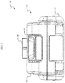
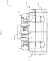
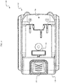
FIG. 1 is a perspective view of a battery pack, according to embodiments described herein. -
FIG. 2 is a front view of the battery pack ofFIG. 1 . -
FIG. 3 is a rear view of the battery pack ofFIG. 1 . -
FIG. 4 is a top view of the battery pack ofFIG. 1 . -
FIG. 5 is a bottom view of the battery pack ofFIG. 1 . -
FIG. 6 is a right-side view of the battery pack ofFIG. 1 . -
FIG. 7 is a rear-perspective view of the battery pack ofFIG. 1 . -
FIG. 8 is a perspective view of the battery pack ofFIG. 1 with a top housing portion of the battery pack removed. -
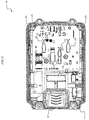
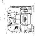
FIG. 9 is a top view of the battery pack ofFIG. 8 with the top housing portion of the battery pack removed. -
FIG. 10 is a front-perspective view of the battery pack ofFIG. 8 with the top housing portion of the battery pack removed. -
FIGS. 11 and 12 illustrate battery cells included in the battery pack ofFIG. 1 . -
FIG. 13 is an electrical schematic diagram for the battery pack ofFIG. 1 , according to embodiments described herein. - Embodiments described herein provide a battery pack for powering any one of a variety of different devices. The battery pack powers the devices by electrically connecting to the devices using at least one terminal. For example, the battery pack electrically connects to a first device using a high-current discharge terminal and a common ground terminal. The battery pack electrically connects to a second device using a low-current discharge terminal and the common ground terminal. Both the high- and low-current discharge terminals are connected to the highest potential battery cell of a plurality of battery cells in the battery pack. As a result, the output voltages of both the high- and low-current discharge terminals are substantially the same. However, a current limiting circuit (e.g., including a switch) is connected between the plurality of battery cells and the low-current discharge terminal for limiting the output current from the low-current discharge terminal.
-
FIG. 1 illustrates abattery pack 100 that is connectable to and supportable by a cordless, hand-held power tool or another battery pack powered device. For example, thebattery pack 100 is configured to be connectable to either high-current draw devices or low-current draw devices. The devices to which thebattery pack 100 is configured to connect include a screwdriver, a drill driver, an impact driver, an impact wrench, a hammer drill, a jigsaw, a bolt cutter, an offset shear, a planar, a table saw, a miter saw, a grinder, a circular saw, a reciprocating saw, a rotary cutter, a scroll saw, a fan, a caulk gun, a drain auger, a hot glue gun, a transfer pump, a blower, a vacuum cleaner, a propane heater, a cement mixer, a sander, a router, a buffer, a nailer, a staple gun, a light, a speaker, a compressor, an inflator, etc. - As shown in
FIGS. 1-7 , thebattery pack 100 includes ahousing 105. Thehousing 105 includes atop housing portion 110 and abottom housing portion 115. Although thebattery pack 100 is illustrated inFIGS. 1-7 including thetop housing portion 110 and thebottom housing portion 115, in some embodiments, thebattery pack 100 includes a left housing portion and a right housing portion. Thebattery pack 100 also includes asupport portion 120 for supporting thebattery pack 100 on, and coupling thebattery pack 100 to, a device such as a hand-held power tool. Thesupport portion 120 includes afirst rail 125 and asecond rail 130 for slidably attaching thebattery pack 100 to the device. Thesupport portion 120 is connectable to a complementary support portion on the device (e.g., a battery pack receiving portion of a power tool). Thebattery pack 100 also includes abutton 135 and a latch orcoupling mechanism 140 for selectively coupling thebattery pack 100 to, or releasing thebattery pack 100 from, the device. In some embodiments, thebutton 135 andcoupling mechanism 140 are considered to be included in the batterypack support portion 120. - The
battery pack 100 includes a plurality of terminals within thesupport portion 120 that are operable to electrically connect one or more battery cells within thebattery pack 100 to the device. As illustrated inFIG. 3 , the plurality of terminals include afirst terminal 145, asecond terminal 150, athird terminal 155, afourth terminal 160, and afifth terminal 165. In some embodiments, thefirst terminal 145 is a battery negative terminal, thesecond terminal 150 is a temperature terminal, thethird terminal 155 is a communication terminal, thefourth terminal 160 is a low power or charging terminal, and thefifth terminal 165 is a battery positive terminal. In some embodiments, thesecond terminal 150 is the communication terminal and thethird terminal 155 is a bypass terminal for bypassing a current sensing circuit. - The
battery pack 100 is removably and interchangeably connected to a device, such as a hand-held power tool, to provide operational power to the device. Theterminals battery pack 100 substantially encloses and covers the terminals on the device when thepack 100 is positioned within a battery pack receiving portion of the device (i.e., thebattery pack 100 functions as a cover for the opening and terminals of the device). Once thebattery pack 100 is disconnected from the device, the terminals on the device are generally exposed to the surrounding environment. In this illustrated embodiment, thebattery pack 100 is designed to substantially follow the contours of a hand-held power tool to match the general shape of an outer casing of a handle of the power tool, and thebattery pack 100 generally increases (i.e., extends) the length of the grip of the power tool (e.g., a portion of the power tool below a motor). - As illustrated in
FIG. 5 , thebottom housing portion 115 of thehousing 105 includes fourfasteners 170 for fastening thebottom housing portion 115 to thetop housing portion 110. For example, in some embodiments, thefasteners 170 are screws that extend vertically through apertures in thebottom housing portion 115 to engage a threaded aperture in thetop housing portion 110. In other embodiments, thetop housing portion 110 and thebottom housing portion 115 are fastened together in a different manner, such as using an adhesive or a fastener other than a screw. -
FIG. 8 illustrates thebattery pack 100 with thetop housing portion 110 removed. With thetop housing portion 110 removed from thebattery pack 100, theterminals first terminal 145 andfifth terminal 165 include first and second pairs of female blade terminals for receiving a male blade terminal from a device connected to thebattery pack 100. Thesecond terminal 150, thethird terminal 155, and thefourth terminal 160 include a single pair of female blade terminals for receiving a male blade terminal from a device connected to thebattery pack 100. In some embodiments, thefirst terminal 145 is used by low power devices and, when a device is connected to thefirst terminal 145, thebattery pack 100 is configured to monitor a discharge current to the device. In such embodiments, thethird terminal 155 can be sa bypass terminal that bypasses a discharge current monitoring circuit (e.g., when thebattery pack 100 is connected to a high power device). Although fiveterminals battery pack 100 is not required to electrically connect to each of theterminals first terminal 145 and thefourth terminal 160. In some embodiments, a charger for thebattery pack 100 electrically connects to thefirst terminal 145, thethird terminal 155, and thefourth terminal 160. In some embodiments, a high- or higher-powered device (e.g., a power tool) electrically connects to thefirst terminal 145, thethird terminal 155, and the fifth terminal. - The
battery pack 100 is configured to include a plurality of battery cells that are arranged and spaced apart from one another by a firstbattery cell holder 180 and a secondbattery cell holder 185, as illustrated inFIGS. 9 and10 . The firstbattery cell holder 180 receives a first end of the battery cells, and the secondbattery cell holder 185 receives a second end of the battery cells. As a result, the firstbattery cell holder 180 and the secondbattery cell holder 185 are configured to sandwich the battery cells and hold the battery cells within thebattery pack housing 105. In some embodiments, the firstbattery cell holder 180 and the secondbattery cell holder 185 are configured as an upper cell holder and a lower cell holder such that the battery cells are sandwiched between the upper cell holder and the lower cell holder. In other embodiments, a single cell holder is used in place of thefirst cell holder 180 and thesecond cell holder 185. - In some embodiments, the
battery pack 100 includes fivebattery cells 190. In other embodiments, thebattery pack 100 includes more orfewer battery cells 190. Thebattery cells 190 can be arranged in series, parallel, or a series-parallel combination. For example, thebattery pack 100 can include a total of fivebattery cells 190 configured in a series arrangement. In some embodiments, a series-parallel combination ofbattery cells 190 allows for an increased voltage and an increased capacity of thebattery pack 100. In other embodiments, thebattery pack 100 includes a different number of battery cells (e.g., between three and twelve battery cells) connected in series, parallel, or a series-parallel combination in order to produce a battery pack having a desired combination of nominal battery pack voltage and capacity. - The
battery cells 190 are, for example, cylindrical 18650 battery cells (18mm diameter and 65mm length). Each battery cell includes acell axis 195, a cell length, LC, and a cell diameter, DC, as illustrated inFIGS. 11 and 12 . In other embodiments, thebattery cells 190 are, for example, cylindrical 14500 battery cells (14mm diameter and 50mm length), 14650 battery cells (14mm diameter and 65mm length), 17500 battery cells (17mm diameter and 50mm length), 17670 battery cells (17mm diameter and 67mm length), 18500 battery cells (18mm diameter and 50mm length), 21650 battery cells (21mm diameter and 65mm length), 21700 battery cells (21mm diameter and 70mm length), etc. Eachbattery cell 190 can be generally cylindrical and can extend along thecell axis 195 parallel to the cylindrical outer cell wall. Also, in thebattery pack 100, eachbattery cell 190 can have a cell length, LC, which is greater than or equal to two times the cell diameter, DC. - The
battery cells 190 are lithium-based battery cells having a chemistry of, for example, lithium-cobalt ("Li-Co"), lithium-manganese ("Li-Mn"), or Li-Mn spinel. In some embodiments, thebattery cells 190 have other suitable lithium or lithium-based chemistries, such as a lithium-based chemistry that includes manganese, etc. The battery cells within thebattery pack 100 provide operational power (e.g., voltage and current) to a device. In some embodiments, eachbattery cell 190 has a nominal voltage of approximately 3.6V, such that thebattery pack 100 has a nominal voltage of approximately 18V. In other embodiments, thebattery cells 190 have different nominal voltages, such as, for example, between 3.6V and 4.2V, and the battery pack has a different nominal voltage, such as, for example, 10.8V, 12V, 14.4V, 24V, 28V, 36V, 50V, between 10.8V and 100V, etc. Thebattery cells 190 also have a capacity of, for example, approximately between 1.0 Ah and 10.0Ah. In exemplary embodiments, the battery cells have capacities of approximately, 1.5Ah, 2.4Ah, 3.0Ah, 4.0Ah, between 1.0Ah and 10.0Ah, etc. - The
battery cells 190 are arranged and spaced apart from one another by the firstbattery cell holder 180 and the secondbattery cell holder 185 to reduce the cell-to-cell heat transfer between thebattery cells 190 and to improve the collection and removal of heat from thebattery cells 190. In this manner, thebattery cells 190 may be able to be maintained in an appropriate temperature operating range (e.g., below 60°C) for longer durations of use. Thebattery cells 190 are also arranged to provide an efficient use of space and to maintain a relatively small pack size. -
FIG. 13 is an electrical schematic diagram of acircuit 200 for thebattery pack 100. In the embodiment illustrated inFIG. 13 , thecircuit 200 includes a plurality ofbattery cells 205A-205E, a control unit 210 (e.g., a processing unit, a processor, a microcontroller, etc.), acommunication unit 215, a current limitingcircuit 220, a switch 225 (e.g., a field-effect transistor ["FET"]), and a plurality of terminals. The plurality of terminals include, for example, a battery pack positive power terminal ("B+"), a charge terminal ("CHG"), a communication terminal ("COMM"), and a battery pack negative power terminal ("B-"). In the embodiment illustrated inFIG. 13 , the battery pack negative terminal, B-, is a common ground terminal for thebattery pack 100. The battery pack negative terminal, B-, can be used in conjunction with either the battery pack positive terminal, B+, or the charge terminal, CHG. In the embodiment illustrated inFIG. 13 , the battery pack positive terminal, B+, is configured as a high-current discharge terminal, HC-DSG, and the charge terminal, CHG, is additionally configured as a low-current discharge terminal, LC-DSG. As a result, thebattery pack 100 is capable of outputting different levels of discharge current to different battery pack terminals. - For example, when the
battery pack 100 is connected to a device that requires a high current output from thebattery pack 100, the device can be configured to connect to the battery pack positive terminal, B+, and the battery pack negative terminal, B-. When thebattery pack 100 is connected to a device that requires a lower current output from thebattery pack 100, the lower power device can be configured to connect to the low-current discharge terminal, LC-DSG, and the battery pack negative terminal, B-. In some embodiments, the high-current discharge terminal, HC-DSG, is capable of providing discharge currents of at least 20 Amps (e.g., as an average discharge current over the rated capacity of the battery pack 100). As a result, thebattery pack 100 is capable of providing discharge currents that are sufficient for powering high power devices, such as power tools. In some embodiments, the low-current discharge terminal, LC-DSG, is capable of providing discharge currents of up to 5 Amps or up to 10 Amps. As a result, thebattery pack 100 is also capable of providing a lower discharge current to a device that requires less current to operate than, for example, a power tool. Both the high-current discharge terminal, HC-DSG, and the low-current discharge terminal, LC-DSG, have output voltages of approximately the same value (e.g., 18V +/- 0.5V). - As shown in the embodiment of
FIG. 13 , the high-current discharge terminal, HC-DSG, is directly connected to the positive end of the highestpotential battery cell 205E of the plurality ofbattery cells 205A-205E. The low-current discharge terminal, LC-DSG, is connected to the highestpotential battery cell 205E of the plurality ofbattery cells 205A-205E through the current limitingcircuit 220 and theswitch 225. In some embodiments, theswitch 225 is included in the current limitingcircuit 220. The current limitingcircuit 220 and/or theswitch 225 are configured to limit a discharge current from thebattery cells 205A-205E that is output through the low-current discharge terminal, LC-DSG. The current limitingcircuit 220 includes active and or passive components (e.g., resistors, capacitors, diodes, transistors, etc.) that are operable to reduce and/or limit the current output of the low-current discharge terminal, LC-DSG. In some embodiments, theswitch 225 is used to reduce or limit the current output of the low-current discharge terminal, LC-DSG. For example, thecontrol unit 210 is configured to control a switching state of theswitch 225 to regulate a duty cycle of the signal output from the low-current discharge terminal, LC-DSG. By controlling theswitch 225, thecontrol unit 210 is able to reduce the output current output from the low-current discharge terminal, LC-DSG. - In some embodiments, the
switch 225 includes a FET for limiting the current output of the low-current discharge terminal, LC-DSG. As is generally known in the art, a FET has a source terminal, a drain terminal, and a gate terminal. Thebattery pack 100 is configured to electrically connect to the drain terminal of the FET. The low-current discharge terminal, LC-DSG, is configured to electrically connect to the source of the FET. With the increase of the current output of the low-current discharge terminal, LC-DSG, the operation of the field-effect transistor switches from a variable resistance region to a saturation region. In the variable resistance region, as the drain-source resistance is small, the current output of the low-current discharge terminal, LC-DSG is not affected. In the saturation region, the drain-source voltage increases significantly with the current output of the low-current discharge terminal, LC-DSG. Hence the drain-source resistance works like a variable resistance having a large resistance value, which provides a function of limiting the output of the low-current discharge terminal, LC-DSG. - Although the current from the low-current discharge terminal, LC-DSG, is reduced, the voltage at the low-current discharge terminal, LC-DSG, is substantially the same as the voltage at the high-current discharge terminal, HC-DSG (e.g., 18V). In other embodiments, the
switch 225 is used in conjunction with the current limiting circuit to reduce or limit the current output of the low-current discharge terminal, LC-DSG. - In some embodiments, the
battery pack 100 is configured to connect to a device using each of the high-current discharge terminal, HC-DSG, and the low-current discharge terminal, LC-DSG. For example, the battery pack can be configured to output a higher discharge current to a device for a primary operation (e.g., powering a motor) using the high-current discharge terminal, HC-DSG. The battery pack can also be configured to output a lower discharge current to the device for a secondary operation (e.g., powering a control or processing unit) using the low-current discharge terminal, LC-DSG. As such, in some embodiments, thebattery pack 100 is not prevented from outputting discharge currents to both the high-current discharge terminal, HC-DSG and the low-current discharge terminal, LC-DSG. In other embodiments, thebattery pack 100 is prevented from outputting discharge currents to both the high-current discharge terminal, HC-DSG and the low-current discharge terminal, LC-DSG. - Thus, embodiments described herein provide, among other things, a battery pack that includes a high-current discharge terminal and a low-current discharge terminal. Various features and advantages are set forth in the following claims.
Claims (15)
- A battery pack comprising:a housing including a battery pack support portion configured to removably mechanically connect the battery pack to a device, the battery pack support portion including a first rail, a second rail, and a coupling mechanism for securing the battery pack to the device;a plurality of battery cells located within the housing, the plurality of battery cells including a highest-potential battery cell and a lowest-potential battery cell;a current limiting circuit connected to a positive terminal of the highest-potential battery cell;a first battery pack terminal configured to electrically connect the battery pack to the device, the first battery pack terminal connected to the positive terminal of the highest-potential battery cell;a second battery pack terminal configured to electrically connect the battery pack to the device, the second battery pack terminal connected to the current limiting circuit; anda third battery pack terminal configured to electrically connect the battery pack to the device, the third battery pack terminal connected to a negative terminal of the lowest-potential battery cell,wherein the current limiting circuit limits an electrical current that can be discharged from the second battery pack terminal to a value that is lower than an electrical current that can be discharged from the first battery pack terminal.
- The battery pack of claim 1, wherein the electrical current that can be discharged from the first battery pack terminal is an average discharge current of at least 20 Amps.
- The battery pack of claim 2, wherein the electrical current that can be discharged from the second battery pack terminal is limited by the current limiting circuit to less than 10 Amps.
- The battery pack of any one of claims 1 to 3, wherein the current limiting circuit includes a switch.
- The battery pack of claim 4, wherein the switch includes a field-effect transistor.
- The battery pack of claim 5, wherein an output voltage at the first battery pack terminal is approximately equal to an output voltage at the second battery pack terminal.
- A battery pack comprising:a housing including a battery pack support portion configured to removably mechanically connect the battery pack to a device, the battery pack support portion including a first rail, a second rail, and a coupling mechanism for securing the battery pack to the device;a plurality of battery cells located within the housing;a current limiting circuit connected to the plurality of battery cells;a first battery pack terminal configured to electrically connect the battery pack to the device, the first battery pack terminal connected to the plurality of battery cells;a second battery pack terminal configured to electrically connect the battery pack to the device, the second battery pack terminal connected to the current limiting circuit; andwherein the current limiting circuit limits an electrical current that can be discharged from the second battery pack terminal to a value that is lower than an electrical current that can be discharged from the first battery pack terminal.
- The battery pack of claim 7, wherein:the first battery pack terminal is connected to a positive terminal of a highest-potential battery cell in the plurality of battery cells;the current limiting circuit is connected to the positive terminal of the highest-potential battery cell; andthe second battery pack terminal is connected to the current limiting circuit.
- The battery pack of claim 7 or 8, wherein the electrical current that can be discharged from the first battery pack terminal is an average discharge current of at least 20 Amps, and optionally, wherein the electrical current that can be discharged from the second battery pack terminal is limited by the current limiting circuit to less than 10 Amps.
- The battery pack of any one of claims 7 to 9, wherein the current limiting circuit includes a switch, and optionally, wherein the switch includes a field-effect transistor.
- The battery pack of claim 10, wherein an output voltage at the first battery pack terminal is approximately equal to an output voltage at the second battery pack terminal.
- A battery pack comprising:a housing including a battery pack support portion configured to removably mechanically connect the battery pack to a device;a plurality of battery cells located within the housing;a current limiting circuit connected to the plurality of battery cells;a first battery pack terminal configured to electrically connect the battery pack to the device, the first battery pack terminal connected to the plurality of battery cells; anda second battery pack terminal configured to electrically connect the battery pack to the device, the second battery pack terminal connected to the current limiting circuit,wherein the current limiting circuit limits an electrical current that can be discharged from the second battery pack terminal to a value that is lower than an electrical current that can be discharged from the first battery pack terminal.
- The battery pack of claim 12, wherein:the first battery pack terminal is connected to a positive terminal of a highest-potential battery cell in the plurality of battery cells;the current limiting circuit is connected to the positive terminal of the highest-potential battery cell; andthe second battery pack terminal is connected to the current limiting circuit.
- The battery pack of claim 12 or 13, wherein the electrical current that can be discharged from the first battery pack terminal is an average discharge current of at least 20 Amps, and optionally, the electrical current that can be discharged from the second battery pack terminal is limited by the current limiting circuit to less than 10 Amps.
- The battery pack of any one of claims 12 to 14, wherein the current limiting circuit includes a switch, and optionally:(i) wherein the switch includes a field-effect transistor; and/or(ii) wherein an output voltage at the first battery pack terminal is approximately equal to an output voltage at the second battery pack terminal.
Applications Claiming Priority (1)
| Application Number | Priority Date | Filing Date | Title |
|---|---|---|---|
| US16/536,422 US11289924B2 (en) | 2019-08-09 | 2019-08-09 | Battery pack including a high- and low-current discharge terminals |
Publications (1)
| Publication Number | Publication Date |
|---|---|
| EP3772769A1 true EP3772769A1 (en) | 2021-02-10 |
Family
ID=72039451
Family Applications (1)
| Application Number | Title | Priority Date | Filing Date |
|---|---|---|---|
| EP20190324.2A Pending EP3772769A1 (en) | 2019-08-09 | 2020-08-10 | Battery pack including a high- and low-current discharge terminals |
Country Status (6)
| Country | Link |
|---|---|
| US (2) | US11289924B2 (en) |
| EP (1) | EP3772769A1 (en) |
| CN (1) | CN213184487U (en) |
| AU (1) | AU2020101748A4 (en) |
| CA (1) | CA3089334A1 (en) |
| MX (1) | MX2020008330A (en) |
Families Citing this family (6)
| Publication number | Priority date | Publication date | Assignee | Title |
|---|---|---|---|---|
| DE102021003702B3 (en) * | 2021-07-19 | 2022-10-27 | Truma Gerätetechnik GmbH & Co. KG | system with equipment |
| JP7660466B2 (en) * | 2021-08-27 | 2025-04-11 | 株式会社マキタ | Electric work machine |
| WO2023246659A1 (en) * | 2022-06-23 | 2023-12-28 | 南京泉峰科技有限公司 | Battery pack |
| CN117317481A (en) * | 2022-06-23 | 2023-12-29 | 南京泉峰科技有限公司 | battery pack |
| US12640582B2 (en) * | 2022-12-02 | 2026-05-26 | Infineon Technologies Ag | Balancing temperature of battery management system circuits |
| CN119208879B (en) * | 2024-09-26 | 2025-09-19 | 孝感楚能新能源创新科技有限公司 | Battery pack convenient for disassembling and assembling battery cells and disassembling and assembling method |
Citations (4)
| Publication number | Priority date | Publication date | Assignee | Title |
|---|---|---|---|---|
| US20050073282A1 (en) * | 2003-10-03 | 2005-04-07 | Carrier David A. | Methods of discharge control for a battery pack of a cordless power tool system, a cordless power tool system and battery pack adapted to provide over-discharge protection and discharge control |
| EP1780867A2 (en) * | 2005-10-28 | 2007-05-02 | BLACK & DECKER INC. | Battery pack for cordless power tools |
| US20100190052A1 (en) * | 2009-01-27 | 2010-07-29 | Umesh Rajani | Battery pack with high and low current discharge terminals |
| US10141551B2 (en) * | 2015-08-20 | 2018-11-27 | Samsung Sdi Co., Ltd. | Battery system |
Family Cites Families (48)
| Publication number | Priority date | Publication date | Assignee | Title |
|---|---|---|---|---|
| US1729169A (en) | 1925-06-04 | 1929-09-24 | United Shoe Machinery Corp | Manufacture of shoes |
| US5122427A (en) * | 1991-08-09 | 1992-06-16 | Skil Corporation | Battery pack |
| US5335133A (en) | 1991-11-29 | 1994-08-02 | Motorola, Inc. | Dual output battery with fault detect |
| US5412308A (en) | 1994-01-06 | 1995-05-02 | Hewlett-Packard Corporation | Dual voltage power supply |
| KR20000019144A (en) | 1998-09-09 | 2000-04-06 | 이수근 | Portable multi-power device using solar battery |
| CN2479648Y (en) | 2001-04-16 | 2002-02-27 | 乔北海 | Multi-power output battery assembling structure |
| US6773842B2 (en) * | 2002-03-26 | 2004-08-10 | Nanotek Instruments, Inc. | Metal-air battery with an extended service life |
| CN2572568Y (en) | 2002-09-15 | 2003-09-10 | 楼森燎 | Accumulator capable of output two-kind of voltage |
| EP1562252A1 (en) | 2004-02-05 | 2005-08-10 | Ford Global Technologies, LLC, A subsidary of Ford Motor Company | Power supply system |
| US7804275B2 (en) | 2007-08-02 | 2010-09-28 | Richard Dellacona | Battery power supply |
| CN201174405Y (en) | 2008-02-04 | 2008-12-31 | 刘礼刚 | Double voltage outputting cylindrical battery |
| US9257865B2 (en) * | 2009-01-22 | 2016-02-09 | Techtronic Power Tools Technology Limited | Wireless power distribution system and method |
| CN201518341U (en) | 2009-09-23 | 2010-06-30 | 赵建和 | A single lithium cell component having a multi-stage charging and discharging interface |
| CN201797008U (en) | 2009-12-31 | 2011-04-13 | 杭州万马高能量电池有限公司 | Lithium-ion battery with quadrupole dedicated to motorcycle starting |
| JP5461221B2 (en) * | 2010-02-12 | 2014-04-02 | 株式会社マキタ | Electric tool powered by multiple battery packs |
| JP5592194B2 (en) * | 2010-08-20 | 2014-09-17 | 三洋電機株式会社 | Battery pack |
| JP5611727B2 (en) * | 2010-08-27 | 2014-10-22 | 三洋電機株式会社 | Power supply |
| US9246340B2 (en) | 2011-02-11 | 2016-01-26 | Intel Corporation | Battery pack |
| CN103907239B (en) | 2011-10-01 | 2017-10-27 | 英特尔公司 | Voltage Management Devices for Stacked Batteries |
| US9112292B2 (en) * | 2012-03-16 | 2015-08-18 | Makita Corporation | Terminal structure |
| US20140342190A1 (en) | 2013-05-20 | 2014-11-20 | Peter Tamburrino | Rechargeable storage battery with improved performance |
| US10468642B2 (en) | 2012-05-18 | 2019-11-05 | Iterna, Llc | Rechargeable storage battery with improved performance |
| EP2698841A1 (en) | 2012-08-14 | 2014-02-19 | Panacis Inc. | Power Belt Share Pack |
| CN203086179U (en) | 2012-12-25 | 2013-07-24 | 比亚迪股份有限公司 | Double-voltage DC supply system |
| TWM461242U (en) | 2013-05-03 | 2013-09-01 | Zhi-Wen Xiao | Mobile power device |
| US9438113B2 (en) | 2013-07-30 | 2016-09-06 | Johnson Controls Technology Company | DC-DC convertor for batteries having multiple positive terminals |
| CN203734332U (en) | 2013-12-26 | 2014-07-23 | 山东精工电子科技有限公司 | Lithium multifunctional standby power supply |
| US11368029B2 (en) | 2014-03-06 | 2022-06-21 | Koki Holdings Co., Ltd. | Portable power supply |
| GB201403971D0 (en) | 2014-03-06 | 2014-04-23 | 7Rdd Ltd | Portable power supply improvements |
| CN204102977U (en) | 2014-07-09 | 2015-01-14 | 深圳市格瑞普电池有限公司 | The Li-ion batteries piles that multivoltage exports |
| CN104064720A (en) | 2014-07-09 | 2014-09-24 | 深圳市格瑞普电池有限公司 | Lithium-ion battery pack with multi-voltage output |
| US10348110B2 (en) * | 2015-02-13 | 2019-07-09 | Makita Corporation | Battery pack |
| CN205029551U (en) | 2015-07-22 | 2016-02-10 | 雅迪科技集团有限公司 | Binary channels multiloop output lithium battery power supply system |
| AU2016315858B2 (en) | 2015-09-02 | 2019-09-26 | Tti (Macao Commercial Offshore) Limited | Power tool, battery pack, and combination, and method of controlling the same |
| CN105576756A (en) | 2016-01-17 | 2016-05-11 | 周虎 | Multi-voltage output power battery system |
| US10483791B2 (en) * | 2016-05-25 | 2019-11-19 | Milwaukee Electric Tool Corporation | Series-connected battery packs, system and method |
| GB201621312D0 (en) | 2016-12-15 | 2017-02-01 | 7Rdd Ltd | Multi power tool system incorporating battery pack |
| EP3602674A4 (en) * | 2017-03-24 | 2021-04-14 | Milwaukee Electric Tool Corporation | BATTERY PACK TERMINAL CONFIGURATION |
| US10439404B2 (en) | 2017-04-13 | 2019-10-08 | Microsoft Technology Licensing, Llc | Hybrid battery pack including bi-directional charge regulator |
| CN107294489A (en) | 2017-05-25 | 2017-10-24 | 河北曹妃甸汉能薄膜太阳能有限公司 | Export the flexible thin-film solar cell component of different voltages |
| CN206865197U (en) | 2017-07-06 | 2018-01-09 | 河南省神行新能源有限公司 | A kind of current distributing input decompression mode output battery |
| CN207021730U (en) | 2017-07-14 | 2018-02-16 | 宁波锂想电子有限公司 | A kind of electric tool |
| CN107302248B (en) | 2017-07-14 | 2024-01-19 | 宁波锂想电子有限公司 | a power tool |
| CN107910490A (en) | 2017-12-07 | 2018-04-13 | 正阳实业投资有限公司 | DC tools and adaptive battery packs |
| MX2020007934A (en) * | 2018-02-02 | 2020-09-03 | Techtronic Cordless Gp | ELECTRIC POWER SPRAYER WITH MULTIPLE VOLTAGE BATTERY SYSTEM AND METHOD THEREFORE. |
| CN109038711B (en) | 2018-07-17 | 2021-09-07 | 东方通信股份有限公司 | A power module with integrated battery charging management and multi-power output |
| CN108963323A (en) | 2018-07-25 | 2018-12-07 | 刘肖俊 | A kind of more power battery devices of high efficiency high practicability |
| CN119074050A (en) * | 2019-07-24 | 2024-12-06 | 深圳迈瑞生物医疗电子股份有限公司 | Shared battery pack, trolley, power supply system and portable ultrasound system |
-
2019
- 2019-08-09 US US16/536,422 patent/US11289924B2/en active Active
-
2020
- 2020-08-07 MX MX2020008330A patent/MX2020008330A/en unknown
- 2020-08-07 CA CA3089334A patent/CA3089334A1/en active Pending
- 2020-08-10 EP EP20190324.2A patent/EP3772769A1/en active Pending
- 2020-08-10 AU AU2020101748A patent/AU2020101748A4/en active Active
- 2020-08-10 CN CN202021648652.3U patent/CN213184487U/en active Active
-
2022
- 2022-03-28 US US17/705,889 patent/US11881733B2/en active Active
Patent Citations (4)
| Publication number | Priority date | Publication date | Assignee | Title |
|---|---|---|---|---|
| US20050073282A1 (en) * | 2003-10-03 | 2005-04-07 | Carrier David A. | Methods of discharge control for a battery pack of a cordless power tool system, a cordless power tool system and battery pack adapted to provide over-discharge protection and discharge control |
| EP1780867A2 (en) * | 2005-10-28 | 2007-05-02 | BLACK & DECKER INC. | Battery pack for cordless power tools |
| US20100190052A1 (en) * | 2009-01-27 | 2010-07-29 | Umesh Rajani | Battery pack with high and low current discharge terminals |
| US10141551B2 (en) * | 2015-08-20 | 2018-11-27 | Samsung Sdi Co., Ltd. | Battery system |
Also Published As
| Publication number | Publication date |
|---|---|
| US11881733B2 (en) | 2024-01-23 |
| US20220216707A1 (en) | 2022-07-07 |
| CN213184487U (en) | 2021-05-11 |
| AU2020101748A4 (en) | 2020-09-24 |
| CA3089334A1 (en) | 2021-02-09 |
| US20210044122A1 (en) | 2021-02-11 |
| US11289924B2 (en) | 2022-03-29 |
| MX2020008330A (en) | 2021-02-10 |
Similar Documents
| Publication | Publication Date | Title |
|---|---|---|
| AU2020101748A4 (en) | Battery pack including a high- and low-current discharge terminals | |
| AU2020101753A4 (en) | Battery pack including staggered battery pack terminals | |
| US11322792B2 (en) | Support member for battery pack top housing | |
| US9553466B2 (en) | Electric power tool system | |
| EP2448036B1 (en) | Electric power tool system | |
| US9472979B2 (en) | Power tool having multiple battery packs | |
| JP5959619B2 (en) | Hand-held power tool and battery pack for hand-held power tool | |
| US10797281B2 (en) | Hand-held power tool and rechargeable battery pack for a hand-held power tool | |
| US12469915B2 (en) | Battery pack support portion configured to accommodate multiple different device interfaces | |
| CN107276156B (en) | Power supply system capable of self-adjusting voltage | |
| WO2010088244A1 (en) | Battery pack with high and low current discharge terminals | |
| EP2391896A1 (en) | Battery pack with high and low current discharge terminals |
Legal Events
| Date | Code | Title | Description |
|---|---|---|---|
| PUAI | Public reference made under article 153(3) epc to a published international application that has entered the european phase |
Free format text: ORIGINAL CODE: 0009012 |
|
| STAA | Information on the status of an ep patent application or granted ep patent |
Free format text: STATUS: THE APPLICATION HAS BEEN PUBLISHED |
|
| AK | Designated contracting states |
Kind code of ref document: A1 Designated state(s): AL AT BE BG CH CY CZ DE DK EE ES FI FR GB GR HR HU IE IS IT LI LT LU LV MC MK MT NL NO PL PT RO RS SE SI SK SM TR |
|
| AX | Request for extension of the european patent |
Extension state: BA ME |
|
| STAA | Information on the status of an ep patent application or granted ep patent |
Free format text: STATUS: REQUEST FOR EXAMINATION WAS MADE |
|
| 17P | Request for examination filed |
Effective date: 20210804 |
|
| RBV | Designated contracting states (corrected) |
Designated state(s): AL AT BE BG CH CY CZ DE DK EE ES FI FR GB GR HR HU IE IS IT LI LT LU LV MC MK MT NL NO PL PT RO RS SE SI SK SM TR |
|
| STAA | Information on the status of an ep patent application or granted ep patent |
Free format text: STATUS: EXAMINATION IS IN PROGRESS |
|
| 17Q | First examination report despatched |
Effective date: 20220310 |