EP3772767A1 - Method of making an electrochemical cell - Google Patents
Method of making an electrochemical cell Download PDFInfo
- Publication number
- EP3772767A1 EP3772767A1 EP19216322.8A EP19216322A EP3772767A1 EP 3772767 A1 EP3772767 A1 EP 3772767A1 EP 19216322 A EP19216322 A EP 19216322A EP 3772767 A1 EP3772767 A1 EP 3772767A1
- Authority
- EP
- European Patent Office
- Prior art keywords
- layer
- plasma spray
- stack
- electrolyte layer
- electrochemical cell
- Prior art date
- Legal status (The legal status is an assumption and is not a legal conclusion. Google has not performed a legal analysis and makes no representation as to the accuracy of the status listed.)
- Pending
Links
- 238000004519 manufacturing process Methods 0.000 title claims abstract description 7
- 239000003792 electrolyte Substances 0.000 claims abstract description 31
- 239000007921 spray Substances 0.000 claims abstract description 31
- 239000000725 suspension Substances 0.000 claims abstract description 23
- 229910052751 metal Inorganic materials 0.000 claims abstract description 19
- 239000002184 metal Substances 0.000 claims abstract description 19
- 238000000151 deposition Methods 0.000 claims abstract description 12
- 238000000034 method Methods 0.000 claims description 15
- 239000000446 fuel Substances 0.000 claims description 13
- 229910052788 barium Inorganic materials 0.000 claims description 12
- DSAJWYNOEDNPEQ-UHFFFAOYSA-N barium atom Chemical compound [Ba] DSAJWYNOEDNPEQ-UHFFFAOYSA-N 0.000 claims description 12
- 239000007787 solid Substances 0.000 claims description 7
- DQBAOWPVHRWLJC-UHFFFAOYSA-N barium(2+);dioxido(oxo)zirconium Chemical compound [Ba+2].[O-][Zr]([O-])=O DQBAOWPVHRWLJC-UHFFFAOYSA-N 0.000 claims description 6
- 238000005868 electrolysis reaction Methods 0.000 claims description 6
- 229910052684 Cerium Inorganic materials 0.000 claims description 5
- GWXLDORMOJMVQZ-UHFFFAOYSA-N cerium Chemical compound [Ce] GWXLDORMOJMVQZ-UHFFFAOYSA-N 0.000 claims description 5
- 239000004215 Carbon black (E152) Substances 0.000 claims description 4
- 229930195733 hydrocarbon Natural products 0.000 claims description 4
- 150000002430 hydrocarbons Chemical class 0.000 claims description 4
- 239000002245 particle Substances 0.000 claims description 4
- 239000000843 powder Substances 0.000 claims description 4
- 230000009977 dual effect Effects 0.000 claims description 3
- 238000001493 electron microscopy Methods 0.000 claims description 3
- 229910000480 nickel oxide Inorganic materials 0.000 claims description 3
- GNRSAWUEBMWBQH-UHFFFAOYSA-N oxonickel Chemical compound [Ni]=O GNRSAWUEBMWBQH-UHFFFAOYSA-N 0.000 claims description 3
- 229910052727 yttrium Inorganic materials 0.000 claims description 3
- VWQVUPCCIRVNHF-UHFFFAOYSA-N yttrium atom Chemical compound [Y] VWQVUPCCIRVNHF-UHFFFAOYSA-N 0.000 claims description 3
- 229910002738 Ba0.5Sr0.5Co0.8Fe0.2O3 Inorganic materials 0.000 claims description 2
- 229910052769 Ytterbium Inorganic materials 0.000 claims description 2
- 229910021523 barium zirconate Inorganic materials 0.000 claims description 2
- 230000008021 deposition Effects 0.000 claims description 2
- 229910052500 inorganic mineral Inorganic materials 0.000 claims description 2
- 239000007788 liquid Substances 0.000 claims description 2
- 239000011707 mineral Substances 0.000 claims description 2
- 230000003647 oxidation Effects 0.000 claims description 2
- 238000007254 oxidation reaction Methods 0.000 claims description 2
- 239000002002 slurry Substances 0.000 claims description 2
- NAWDYIZEMPQZHO-UHFFFAOYSA-N ytterbium Chemical compound [Yb] NAWDYIZEMPQZHO-UHFFFAOYSA-N 0.000 claims description 2
- 229910021522 yttrium-doped barium zirconate Inorganic materials 0.000 claims description 2
- 239000000463 material Substances 0.000 description 5
- LFQSCWFLJHTTHZ-UHFFFAOYSA-N Ethanol Chemical compound CCO LFQSCWFLJHTTHZ-UHFFFAOYSA-N 0.000 description 4
- 239000000919 ceramic Substances 0.000 description 4
- VNWKTOKETHGBQD-UHFFFAOYSA-N methane Chemical compound C VNWKTOKETHGBQD-UHFFFAOYSA-N 0.000 description 4
- 239000002131 composite material Substances 0.000 description 3
- 239000007769 metal material Substances 0.000 description 3
- 238000004627 transmission electron microscopy Methods 0.000 description 3
- PXHVJJICTQNCMI-UHFFFAOYSA-N Nickel Chemical compound [Ni] PXHVJJICTQNCMI-UHFFFAOYSA-N 0.000 description 2
- 150000001875 compounds Chemical class 0.000 description 2
- 238000010586 diagram Methods 0.000 description 2
- 239000002001 electrolyte material Substances 0.000 description 2
- -1 nickel chromium aluminum yttrium Chemical compound 0.000 description 2
- 238000010248 power generation Methods 0.000 description 2
- 239000012078 proton-conducting electrolyte Substances 0.000 description 2
- 238000004626 scanning electron microscopy Methods 0.000 description 2
- 229910001220 stainless steel Inorganic materials 0.000 description 2
- UFHFLCQGNIYNRP-UHFFFAOYSA-N Hydrogen Chemical compound [H][H] UFHFLCQGNIYNRP-UHFFFAOYSA-N 0.000 description 1
- 229910001030 Iron–nickel alloy Inorganic materials 0.000 description 1
- 229910002823 PrBa0.5Sr0.5Co1.5Fe0.5O5+δ Inorganic materials 0.000 description 1
- 239000010405 anode material Substances 0.000 description 1
- 150000001553 barium compounds Chemical class 0.000 description 1
- RQPZNWPYLFFXCP-UHFFFAOYSA-L barium dihydroxide Chemical compound [OH-].[OH-].[Ba+2] RQPZNWPYLFFXCP-UHFFFAOYSA-L 0.000 description 1
- 229910001863 barium hydroxide Inorganic materials 0.000 description 1
- AYJRCSIUFZENHW-DEQYMQKBSA-L barium(2+);oxomethanediolate Chemical compound [Ba+2].[O-][14C]([O-])=O AYJRCSIUFZENHW-DEQYMQKBSA-L 0.000 description 1
- CSSYLTMKCUORDA-UHFFFAOYSA-N barium(2+);oxygen(2-) Chemical class [O-2].[Ba+2] CSSYLTMKCUORDA-UHFFFAOYSA-N 0.000 description 1
- 229910021525 ceramic electrolyte Inorganic materials 0.000 description 1
- 230000002860 competitive effect Effects 0.000 description 1
- SYBFKRWZBUQDGU-UHFFFAOYSA-N copper manganese(2+) oxygen(2-) Chemical compound [O--].[O--].[Mn++].[Cu++] SYBFKRWZBUQDGU-UHFFFAOYSA-N 0.000 description 1
- 238000005516 engineering process Methods 0.000 description 1
- 229910052739 hydrogen Inorganic materials 0.000 description 1
- 239000001257 hydrogen Substances 0.000 description 1
- 239000006194 liquid suspension Substances 0.000 description 1
- 238000005259 measurement Methods 0.000 description 1
- 229910044991 metal oxide Inorganic materials 0.000 description 1
- 150000004706 metal oxides Chemical class 0.000 description 1
- 239000000203 mixture Substances 0.000 description 1
- 238000012986 modification Methods 0.000 description 1
- 230000004048 modification Effects 0.000 description 1
- 229910052759 nickel Inorganic materials 0.000 description 1
- 239000010935 stainless steel Substances 0.000 description 1
Images

Classifications
-
- H—ELECTRICITY
- H01—ELECTRIC ELEMENTS
- H01M—PROCESSES OR MEANS, e.g. BATTERIES, FOR THE DIRECT CONVERSION OF CHEMICAL ENERGY INTO ELECTRICAL ENERGY
- H01M8/00—Fuel cells; Manufacture thereof
- H01M8/10—Fuel cells with solid electrolytes
- H01M8/12—Fuel cells with solid electrolytes operating at high temperature, e.g. with stabilised ZrO2 electrolyte
- H01M8/1213—Fuel cells with solid electrolytes operating at high temperature, e.g. with stabilised ZrO2 electrolyte characterised by the electrode/electrolyte combination or the supporting material
-
- H—ELECTRICITY
- H01—ELECTRIC ELEMENTS
- H01M—PROCESSES OR MEANS, e.g. BATTERIES, FOR THE DIRECT CONVERSION OF CHEMICAL ENERGY INTO ELECTRICAL ENERGY
- H01M8/00—Fuel cells; Manufacture thereof
- H01M8/10—Fuel cells with solid electrolytes
- H01M8/12—Fuel cells with solid electrolytes operating at high temperature, e.g. with stabilised ZrO2 electrolyte
- H01M8/1213—Fuel cells with solid electrolytes operating at high temperature, e.g. with stabilised ZrO2 electrolyte characterised by the electrode/electrolyte combination or the supporting material
- H01M8/1226—Fuel cells with solid electrolytes operating at high temperature, e.g. with stabilised ZrO2 electrolyte characterised by the electrode/electrolyte combination or the supporting material characterised by the supporting layer
-
- H—ELECTRICITY
- H01—ELECTRIC ELEMENTS
- H01M—PROCESSES OR MEANS, e.g. BATTERIES, FOR THE DIRECT CONVERSION OF CHEMICAL ENERGY INTO ELECTRICAL ENERGY
- H01M10/00—Secondary cells; Manufacture thereof
- H01M10/05—Accumulators with non-aqueous electrolyte
- H01M10/052—Li-accumulators
- H01M10/0525—Rocking-chair batteries, i.e. batteries with lithium insertion or intercalation in both electrodes; Lithium-ion batteries
-
- H—ELECTRICITY
- H01—ELECTRIC ELEMENTS
- H01M—PROCESSES OR MEANS, e.g. BATTERIES, FOR THE DIRECT CONVERSION OF CHEMICAL ENERGY INTO ELECTRICAL ENERGY
- H01M4/00—Electrodes
- H01M4/02—Electrodes composed of, or comprising, active material
- H01M4/04—Processes of manufacture in general
- H01M4/0402—Methods of deposition of the material
- H01M4/0404—Methods of deposition of the material by coating on electrode collectors
-
- H—ELECTRICITY
- H01—ELECTRIC ELEMENTS
- H01M—PROCESSES OR MEANS, e.g. BATTERIES, FOR THE DIRECT CONVERSION OF CHEMICAL ENERGY INTO ELECTRICAL ENERGY
- H01M4/00—Electrodes
- H01M4/02—Electrodes composed of, or comprising, active material
- H01M4/13—Electrodes for accumulators with non-aqueous electrolyte, e.g. for lithium-accumulators; Processes of manufacture thereof
- H01M4/134—Electrodes based on metals, Si or alloys
-
- H—ELECTRICITY
- H01—ELECTRIC ELEMENTS
- H01M—PROCESSES OR MEANS, e.g. BATTERIES, FOR THE DIRECT CONVERSION OF CHEMICAL ENERGY INTO ELECTRICAL ENERGY
- H01M8/00—Fuel cells; Manufacture thereof
- H01M8/10—Fuel cells with solid electrolytes
- H01M8/12—Fuel cells with solid electrolytes operating at high temperature, e.g. with stabilised ZrO2 electrolyte
- H01M8/124—Fuel cells with solid electrolytes operating at high temperature, e.g. with stabilised ZrO2 electrolyte characterised by the process of manufacturing or by the material of the electrolyte
-
- H—ELECTRICITY
- H01—ELECTRIC ELEMENTS
- H01M—PROCESSES OR MEANS, e.g. BATTERIES, FOR THE DIRECT CONVERSION OF CHEMICAL ENERGY INTO ELECTRICAL ENERGY
- H01M8/00—Fuel cells; Manufacture thereof
- H01M8/10—Fuel cells with solid electrolytes
- H01M8/12—Fuel cells with solid electrolytes operating at high temperature, e.g. with stabilised ZrO2 electrolyte
- H01M2008/1293—Fuel cells with solid oxide electrolytes
-
- H—ELECTRICITY
- H01—ELECTRIC ELEMENTS
- H01M—PROCESSES OR MEANS, e.g. BATTERIES, FOR THE DIRECT CONVERSION OF CHEMICAL ENERGY INTO ELECTRICAL ENERGY
- H01M2300/00—Electrolytes
- H01M2300/0017—Non-aqueous electrolytes
- H01M2300/0065—Solid electrolytes
- H01M2300/0068—Solid electrolytes inorganic
-
- Y—GENERAL TAGGING OF NEW TECHNOLOGICAL DEVELOPMENTS; GENERAL TAGGING OF CROSS-SECTIONAL TECHNOLOGIES SPANNING OVER SEVERAL SECTIONS OF THE IPC; TECHNICAL SUBJECTS COVERED BY FORMER USPC CROSS-REFERENCE ART COLLECTIONS [XRACs] AND DIGESTS
- Y02—TECHNOLOGIES OR APPLICATIONS FOR MITIGATION OR ADAPTATION AGAINST CLIMATE CHANGE
- Y02E—REDUCTION OF GREENHOUSE GAS [GHG] EMISSIONS, RELATED TO ENERGY GENERATION, TRANSMISSION OR DISTRIBUTION
- Y02E60/00—Enabling technologies; Technologies with a potential or indirect contribution to GHG emissions mitigation
- Y02E60/10—Energy storage using batteries
-
- Y—GENERAL TAGGING OF NEW TECHNOLOGICAL DEVELOPMENTS; GENERAL TAGGING OF CROSS-SECTIONAL TECHNOLOGIES SPANNING OVER SEVERAL SECTIONS OF THE IPC; TECHNICAL SUBJECTS COVERED BY FORMER USPC CROSS-REFERENCE ART COLLECTIONS [XRACs] AND DIGESTS
- Y02—TECHNOLOGIES OR APPLICATIONS FOR MITIGATION OR ADAPTATION AGAINST CLIMATE CHANGE
- Y02E—REDUCTION OF GREENHOUSE GAS [GHG] EMISSIONS, RELATED TO ENERGY GENERATION, TRANSMISSION OR DISTRIBUTION
- Y02E60/00—Enabling technologies; Technologies with a potential or indirect contribution to GHG emissions mitigation
- Y02E60/30—Hydrogen technology
- Y02E60/50—Fuel cells
-
- Y—GENERAL TAGGING OF NEW TECHNOLOGICAL DEVELOPMENTS; GENERAL TAGGING OF CROSS-SECTIONAL TECHNOLOGIES SPANNING OVER SEVERAL SECTIONS OF THE IPC; TECHNICAL SUBJECTS COVERED BY FORMER USPC CROSS-REFERENCE ART COLLECTIONS [XRACs] AND DIGESTS
- Y02—TECHNOLOGIES OR APPLICATIONS FOR MITIGATION OR ADAPTATION AGAINST CLIMATE CHANGE
- Y02P—CLIMATE CHANGE MITIGATION TECHNOLOGIES IN THE PRODUCTION OR PROCESSING OF GOODS
- Y02P70/00—Climate change mitigation technologies in the production process for final industrial or consumer products
- Y02P70/50—Manufacturing or production processes characterised by the final manufactured product
Definitions
- Exemplary embodiments pertain to the art of electrochemical cells, more particularly, to a method of making an electrochemical cell using suspension plasma spray.
- Oxide fuel cells have many potential applications. For example, in the aerospace industry, potential applications include electrolysis, auxiliary power generation, and aircraft propulsion.
- solid oxide fuel cells are compatible with hydrocarbon fuels, such as methane, ethanol, and jet fuels.
- Metal-supported electrochemical cell stacks, enabled by proton-conducting electrolyte materials, can also provide fast startup times, fast transit response, and high power density.
- solid oxide fuel cell technology is often very costly to manufacture.
- a method of making an electrochemical cell comprising: depositing an anode layer on a surface of a porous metal support layer; depositing an electrolyte layer on a surface of the anode layer, wherein the electrolyte layer is deposited via suspension plasma spray, wherein the electrolyte layer conducts protons; and depositing a cathode layer on a surface of the electrolyte layer.
- Also disclosed is a stack comprising two or more of the electrochemical cell.
- an electrochemical cell 10 can include a porous metal support layer 12, an oxide protection layer 13, an anode layer 14, an electrolyte layer 16, and a cathode layer 18.
- the electrochemical cell can be a solid oxide fuel cell, a solid oxide electrolysis cell, or a combination thereof.
- the porous metal support layer 12 can comprise metal materials, metal ceramic composite materials, or combinations thereof.
- the porous metal support layer 12 can comprise nickel, iron nickel alloy, nickel chromium aluminum yttrium, stainless steel, for example, ferritic stainless steel, or any combination thereof.
- the porous metal support layer 12 can have a porosity of about 10% to about 50% based on a total volume of the porous metal support layer 12. Porosity can be measured using any suitable means, for example, electron microscopy, for example, transmission electron microscopy or scanning electron microscopy.
- An anode layer 14 can be deposited on a surface of the porous metal support layer 12.
- the anode layer 14 can comprise metal materials, metal ceramic composite materials, or combinations thereof.
- the anode layer 14 can comprise nickel oxide and a ceramic electrolyte material.
- the anode layer 14 can comprise a porous structure.
- the anode layer 14 can comprise a mixture of porous nickel oxide and electrolyte material.
- An oxidation protection layer 13 can also be deposited in between the anode layer 14 and the porous metal support layer 12.
- the oxide protection layer 13 can comprise a metal oxide, for example, copper manganese oxide.
- the anode layer 14 can be deposited on a surface of the metal support layer 12 via suspension plasma spray or auxiliary plasma spray.
- a powdered form of the metal and/or ceramic anode materials can be suspended in a liquid (e.g., aqueous or organic).
- the powder particles can be heated (e.g., sintered) until they reach a molten state.
- the resulting material can then be jetted onto the desired surface.
- the use of finer powders can result in finer microstructures and thinner layers.
- the suspension plasma spray can comprise particles less than 15 micrometers in average diameter, for example, about 1 micrometer to about 15 micrometers in average diameter.
- Average diameter can be measured using any suitable means, for example, electron microscopy, for example, transmission electron microscopy or scanning electron microscopy.
- Suspension plasma spray can result in layers that are, for example, less than or equal to 100 micrometers thick, for example, about 10 micrometers to about 50 micrometers thick.
- auxiliary plasma spray In an auxiliary plasma spray method, only the powder is used (i.e. no liquid suspension). Use of auxiliary plasma spray can result in coarser microstructures and thicker layers.
- the auxiliary plasma spray can comprise particles about 10 micrometers to about 100 micrometers in average diameter, for example, about 20 micrometers to about 30 micrometers in average diameter, as measured by, for example, transmission electron microscopy.
- the suspension plasma spray and the auxiliary plasma spray can be applied via dual jetting nozzles.
- dual jetting nozzles can be used when a layer being deposited comprises two or more components (e.g., anode layer 14).
- An electrolyte layer 16 can be deposited on a surface of the anode layer 14.
- the electrolyte layer 16 can be deposited on a surface of the anode layer 14 via suspension plasma spray.
- the electrolyte layer 16 can be proton conducting.
- the proton conducting nature of the electrolyte layer 16 can allow the electrochemical cell 10 to be used for electrolysis.
- the electrolyte layer 16 can comprise metal materials, ceramic composite materials, or combinations thereof.
- the electrolyte layer 16 can comprise barium compounds doped with one or more additional materials (e.g., a perovskite structure).
- the electrolyte layer 16 can comprise yttrium doped barium zirconate, cerium doped barium yttrium zirconate, cerium/ytterbium doped barium yttrium zirconate, yttrium/tin doped barium zirconate, or a combination thereof.
- doping levels for the electrolyte layer 16 can be about 5% to about 20% yttrium, about 20% to about 80% cerium, or combinations thereof.
- a stoichiometric ratio for these compounds can include barium in a stoichiometric amount of 1.0, for example, Ba 1.0 Y 0.2 Z 0.8 O 3 .
- the electrolyte layer 16 can comprise greater than or equal to 35% barium by weight based on a total weight of the electrolyte layer 16, for example, greater than or equal to 40% barium by weight, for example, about 35% to about 55% barium by weight.
- excess barium in the form of barium carbonate, barium hydroxide, or combinations thereof, can be added to the suspension plasma spray before deposition on the anode layer 14.
- the amount of barium by weight in the suspension plasma spray can be 10% to 30% greater, for example, about 20% greater, than the amount of barium desired in the final electrolyte layer 16.
- a cathode layer 18 can be deposited on a surface of the electrolyte layer 16.
- the cathode layer 18 can be deposited via any suitable method, for example, suspension plasma spray, auxiliary plasma spray, slurry application, or a combination thereof.
- both the anode layer and the cathode layer are deposited via suspension plasma spray.
- the cathode layer can comprise perovskite minerals and/or barium oxides.
- the cathode layer can comprise Ba 0.5 Pr 0.5 CoO 3 , Ba 0.5 Sr 0.5 Co 0.8 Fe 0.2 O 3 , Ba(Ce 1-x Bi x )O 3 , PrBa 0.5 Sr 0.5 Co 1.5 Fe 0.5 O 5+ ⁇ , or a combination thereof.
- a stack 20 can include two or more of the electrochemical cell 10, a metal mesh layer 22, and a flow channel layer 24.
- the stack 20 can include a metal mesh layer 22 deposited in between two electrochemical cells 10.
- the stack 20 can include a flow channel layer deposited in between two electrochemical cells 10.
- the electrochemical cell 10 and/or stack 20 has many useful applications.
- the electrochemical cell 10 and/or stack 20 can be used in reverse for steam electrolysis. Electrolysis can be a highly efficient and cost competitive process for hydrogen generation when coupled with nuclear power or renewable sources such as wind or solar.
- the electrochemical cell 10 and/or stack 20 has applications in aerospace such as auxiliary power generation and aircraft propulsion.
- the electrochemical cell 10 and/or stack 20 is compatible with hydrocarbon fuels, such as methane, ethanol, and jet fuels.
- the electrochemical cell 10 and/or stack 20 can come into contact with a hydrocarbon fuel during use.
- An operating temperature of the electrochemical cell 10 and/or stack 20 can be less than or equal to 700°C (1292°F), for example, about 500°C (932°F) to about 650°C (1202°F).
- the electrochemical cell 10 and/or stack 20, enabled by proton-conducting electrolyte materials, can also provide fast startup times, fast transit response, and high power density.
Landscapes
- Chemical & Material Sciences (AREA)
- Engineering & Computer Science (AREA)
- Electrochemistry (AREA)
- General Chemical & Material Sciences (AREA)
- Chemical Kinetics & Catalysis (AREA)
- Manufacturing & Machinery (AREA)
- Life Sciences & Earth Sciences (AREA)
- Sustainable Development (AREA)
- Sustainable Energy (AREA)
- Materials Engineering (AREA)
- Fuel Cell (AREA)
- Electrolytic Production Of Non-Metals, Compounds, Apparatuses Therefor (AREA)
- Electrodes For Compound Or Non-Metal Manufacture (AREA)
- Inert Electrodes (AREA)
Abstract
Description
- This invention was made with U.S. Government support under contract DE-EE0008080 awarded by the Department of Energy. The U.S. Government has certain rights in the invention.
- Exemplary embodiments pertain to the art of electrochemical cells, more particularly, to a method of making an electrochemical cell using suspension plasma spray.
- Oxide fuel cells have many potential applications. For example, in the aerospace industry, potential applications include electrolysis, auxiliary power generation, and aircraft propulsion. For example, solid oxide fuel cells are compatible with hydrocarbon fuels, such as methane, ethanol, and jet fuels. Metal-supported electrochemical cell stacks, enabled by proton-conducting electrolyte materials, can also provide fast startup times, fast transit response, and high power density. However, solid oxide fuel cell technology is often very costly to manufacture.
- Therefore, there is a need to develop a method of manufacturing electrochemical fuel cells, such as solid oxide fuel cells, which is more efficient and less costly.
- Disclosed is a method of making an electrochemical cell, comprising: depositing an anode layer on a surface of a porous metal support layer; depositing an electrolyte layer on a surface of the anode layer, wherein the electrolyte layer is deposited via suspension plasma spray, wherein the electrolyte layer conducts protons; and depositing a cathode layer on a surface of the electrolyte layer.
- Also disclosed is a stack comprising two or more of the electrochemical cell.
- The following descriptions should not be considered limiting in any way. With reference to the accompanying drawings, like elements are numbered alike:
-
FIG. 1 is a simplified diagram representing an electrochemical cell according to an exemplary embodiment; and -
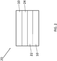
FIG. 2 is a simplified diagram representing an electrochemical cell stack according to an exemplary embodiment. - A detailed description of one or more embodiments of the disclosed apparatus and method are presented herein by way of exemplification and not limitation with reference to the Figures.
- Referring to
FIG. 1 , anelectrochemical cell 10 can include a porousmetal support layer 12, anoxide protection layer 13, ananode layer 14, anelectrolyte layer 16, and acathode layer 18. For example, the electrochemical cell can be a solid oxide fuel cell, a solid oxide electrolysis cell, or a combination thereof. - The porous
metal support layer 12 can comprise metal materials, metal ceramic composite materials, or combinations thereof. For example, the porousmetal support layer 12 can comprise nickel, iron nickel alloy, nickel chromium aluminum yttrium, stainless steel, for example, ferritic stainless steel, or any combination thereof. The porousmetal support layer 12 can have a porosity of about 10% to about 50% based on a total volume of the porousmetal support layer 12. Porosity can be measured using any suitable means, for example, electron microscopy, for example, transmission electron microscopy or scanning electron microscopy. - An
anode layer 14 can be deposited on a surface of the porousmetal support layer 12. Theanode layer 14 can comprise metal materials, metal ceramic composite materials, or combinations thereof. For example, theanode layer 14 can comprise nickel oxide and a ceramic electrolyte material. Theanode layer 14 can comprise a porous structure. For example, theanode layer 14 can comprise a mixture of porous nickel oxide and electrolyte material. Anoxidation protection layer 13 can also be deposited in between theanode layer 14 and the porousmetal support layer 12. For example, theoxide protection layer 13 can comprise a metal oxide, for example, copper manganese oxide. - The
anode layer 14 can be deposited on a surface of themetal support layer 12 via suspension plasma spray or auxiliary plasma spray. For example, in a suspension plasma spray, a powdered form of the metal and/or ceramic anode materials can be suspended in a liquid (e.g., aqueous or organic). The powder particles can be heated (e.g., sintered) until they reach a molten state. The resulting material can then be jetted onto the desired surface. The use of finer powders can result in finer microstructures and thinner layers. For example, the suspension plasma spray can comprise particles less than 15 micrometers in average diameter, for example, about 1 micrometer to about 15 micrometers in average diameter. Average diameter can be measured using any suitable means, for example, electron microscopy, for example, transmission electron microscopy or scanning electron microscopy. Suspension plasma spray can result in layers that are, for example, less than or equal to 100 micrometers thick, for example, about 10 micrometers to about 50 micrometers thick. - In an auxiliary plasma spray method, only the powder is used (i.e. no liquid suspension). Use of auxiliary plasma spray can result in coarser microstructures and thicker layers. For example, the auxiliary plasma spray can comprise particles about 10 micrometers to about 100 micrometers in average diameter, for example, about 20 micrometers to about 30 micrometers in average diameter, as measured by, for example, transmission electron microscopy. The suspension plasma spray and the auxiliary plasma spray can be applied via dual jetting nozzles. For example, dual jetting nozzles can be used when a layer being deposited comprises two or more components (e.g., anode layer 14).
- An
electrolyte layer 16 can be deposited on a surface of theanode layer 14. For example, theelectrolyte layer 16 can be deposited on a surface of theanode layer 14 via suspension plasma spray. Theelectrolyte layer 16 can be proton conducting. For example, the proton conducting nature of theelectrolyte layer 16 can allow theelectrochemical cell 10 to be used for electrolysis. Theelectrolyte layer 16 can comprise metal materials, ceramic composite materials, or combinations thereof. Theelectrolyte layer 16 can comprise barium compounds doped with one or more additional materials (e.g., a perovskite structure). For example, theelectrolyte layer 16 can comprise yttrium doped barium zirconate, cerium doped barium yttrium zirconate, cerium/ytterbium doped barium yttrium zirconate, yttrium/tin doped barium zirconate, or a combination thereof. For example, doping levels for theelectrolyte layer 16 can be about 5% to about 20% yttrium, about 20% to about 80% cerium, or combinations thereof. A stoichiometric ratio for these compounds can include barium in a stoichiometric amount of 1.0, for example, Ba1.0Y0.2Z0.8O3. Theelectrolyte layer 16 can comprise greater than or equal to 35% barium by weight based on a total weight of theelectrolyte layer 16, for example, greater than or equal to 40% barium by weight, for example, about 35% to about 55% barium by weight. - Barium can be lost during the suspension plasma spray process. In order to compensate for this loss, and ensure that a suitable amount of barium is present in the
final electrolyte layer 16, excess barium can be added to the suspension plasma spray before theelectrolyte layer 16 is deposited. For example, excess barium can be added directly to a BYZ perovskite compound used in the suspension plasma spray. For example, if Ba1.0Y0.2Z0.8O3 is desired in thefinal electrolyte layer 16, then Ba1.0+xY0.2Z0.8O3 can be used in the suspension plasma spray, wherein x is 0.1 to 0.3, for example, about 0.2. Additionally, or alternatively, excess barium in the form of barium carbonate, barium hydroxide, or combinations thereof, can be added to the suspension plasma spray before deposition on theanode layer 14. For example, the amount of barium by weight in the suspension plasma spray can be 10% to 30% greater, for example, about 20% greater, than the amount of barium desired in thefinal electrolyte layer 16. - A
cathode layer 18 can be deposited on a surface of theelectrolyte layer 16. For example, thecathode layer 18 can be deposited via any suitable method, for example, suspension plasma spray, auxiliary plasma spray, slurry application, or a combination thereof. In an embodiment, both the anode layer and the cathode layer are deposited via suspension plasma spray. The cathode layer can comprise perovskite minerals and/or barium oxides. For example, the cathode layer can comprise Ba0.5Pr0.5CoO3, Ba0.5Sr0.5Co0.8Fe0.2O3, Ba(Ce1-xBix)O3, PrBa0.5Sr0.5Co1.5Fe0.5O5+δ, or a combination thereof. - Referring to
FIG. 2 , astack 20 can include two or more of theelectrochemical cell 10, ametal mesh layer 22, and aflow channel layer 24. For example, thestack 20 can include ametal mesh layer 22 deposited in between twoelectrochemical cells 10. Thestack 20 can include a flow channel layer deposited in between twoelectrochemical cells 10. - The
electrochemical cell 10 and/or stack 20 has many useful applications. For example, theelectrochemical cell 10 and/or stack 20 can be used in reverse for steam electrolysis. Electrolysis can be a highly efficient and cost competitive process for hydrogen generation when coupled with nuclear power or renewable sources such as wind or solar. Theelectrochemical cell 10 and/or stack 20 has applications in aerospace such as auxiliary power generation and aircraft propulsion. For example, theelectrochemical cell 10 and/or stack 20 is compatible with hydrocarbon fuels, such as methane, ethanol, and jet fuels. Theelectrochemical cell 10 and/or stack 20 can come into contact with a hydrocarbon fuel during use. An operating temperature of theelectrochemical cell 10 and/or stack 20 can be less than or equal to 700°C (1292°F), for example, about 500°C (932°F) to about 650°C (1202°F). Theelectrochemical cell 10 and/or stack 20, enabled by proton-conducting electrolyte materials, can also provide fast startup times, fast transit response, and high power density. - The term "about" is intended to include the degree of error associated with measurement of the particular quantity based upon the equipment available at the time of filing the application.
- The terminology used herein is for the purpose of describing particular embodiments only and is not intended to be limiting of the present disclosure. As used herein, the singular forms "a", "an" and "the" are intended to include the plural forms as well, unless the context clearly indicates otherwise. It will be further understood that the terms "comprises" and/or "comprising," when used in this specification, specify the presence of stated features, integers, steps, operations, elements, and/or components (and encompasses "consist(s) of', "consisting of', "consist(s) essentially of' and "consisting essentially of'), but do not necessarily preclude the presence or addition of one or more other features, integers, steps, operations, element components, and/or groups thereof.
- While the present disclosure has been described with reference to an exemplary embodiment or embodiments, it will be understood by those skilled in the art that various changes may be made and equivalents may be substituted for elements thereof without departing from the scope of the invention as defined by the claims. In addition, many modifications may be made to adapt a particular situation or material to the teachings of the present disclosure without departing from the scope of the invention. Therefore, it is intended that the present disclosure not be limited to the particular embodiment disclosed as the best mode contemplated for carrying out this present disclosure, but that the present disclosure will include all embodiments falling within the scope of the claims.
Claims (15)
- A method of making an electrochemical cell, comprising:depositing an anode layer (14) on a surface of a porous metal support layer (12);depositing an electrolyte layer (16) on a surface of the anode layer, wherein the electrolyte layer is deposited via suspension plasma spray, wherein the electrolyte layer conducts protons; anddepositing a cathode layer (18) on a surface of the electrolyte layer.
- The method of Claim 1, wherein the electrochemical cell is a solid oxide fuel cell, a solid oxide electrolysis cell, or a combination thereof.
- The method of Claim 1 or 2, wherein the anode layer is deposited via suspension plasma spray or auxiliary plasma spray.
- The method of Claim 1, 2 or 3, further comprising depositing an oxidation protection layer (15) in between the anode layer and the metal support layer.
- The method of any preceding claim, wherein the metal support layer, the anode layer, or a combination thereof, comprises a porous structure.
- The method of any preceding claim, wherein the anode layer comprises nickel oxide, and/or wherein the electrolyte layer comprises yttrium doped barium zirconate, cerium doped barium yttrium zirconate, cerium/ytterbium doped barium yttrium zirconate, yttrium/tin doped barium zirconate, or a combination thereof, and optionally the electrolyte layer comprises greater than or equal to 35% barium by weight based on a total weight of the electrolyte layer; and/or wherein the cathode layer comprises a perovskite mineral and optionally wherein the cathode layer comprises Ba0.5Pr0.5CoO3, Ba0.5Sr0.5Co0.8Fe0.2O3, Ba(Ce1-xBix)O3, PrBa0.5Sr0.5Co0.5Fe0.5O5+δ, or a combination thereof.
- The method of any preceding claim, wherein the cathode layer is deposited via suspension plasma spray, auxiliary plasma spray, or slurry application, and optionally wherein the anode layer and the cathode layer are deposited via suspension plasma spray.
- The method of any preceding claim, wherein deposition occurs via dual jetting nozzles.
- The method of any preceding claim, wherein an operating temperature of the electrochemical cell is about 500°C to about 700°C.
- The method of any preceding claim, wherein the suspension plasma spray comprises particles about 1 micrometers to about 15 micrometers in average diameter, as measured by electron microscopy.
- The method of any preceding claim, wherein the suspension plasma spray comprises a powder suspended in a liquid.
- A stack comprising two or more of the electrochemical cell (10) of any preceding claim.
- The stack of Claim 12, further comprising a metal mesh layer (22) deposited between two electrochemical cells.
- The stack of Claim 12 or 13, further comprising a flow channel layer (24) deposited between two electrochemical cells.
- The stack of Claim 12, 13 or 14, further comprising a hydrocarbon fuel in contact with the stack.
Applications Claiming Priority (1)
| Application Number | Priority Date | Filing Date | Title |
|---|---|---|---|
| US16/531,357 US11437640B2 (en) | 2019-08-05 | 2019-08-05 | Method of making an electrochemical cell |
Publications (1)
| Publication Number | Publication Date |
|---|---|
| EP3772767A1 true EP3772767A1 (en) | 2021-02-10 |
Family
ID=68917467
Family Applications (1)
| Application Number | Title | Priority Date | Filing Date |
|---|---|---|---|
| EP19216322.8A Pending EP3772767A1 (en) | 2019-08-05 | 2019-12-13 | Method of making an electrochemical cell |
Country Status (3)
| Country | Link |
|---|---|
| US (1) | US11437640B2 (en) |
| EP (1) | EP3772767A1 (en) |
| JP (1) | JP7542233B2 (en) |
Families Citing this family (1)
| Publication number | Priority date | Publication date | Assignee | Title |
|---|---|---|---|---|
| JP7444683B2 (en) * | 2020-03-31 | 2024-03-06 | 大阪瓦斯株式会社 | Metal support, electrochemical element, electrochemical module, electrochemical device, energy system, solid oxide fuel cell, solid oxide electrolytic cell, and method for producing metal support |
Citations (3)
| Publication number | Priority date | Publication date | Assignee | Title |
|---|---|---|---|---|
| CN101183716A (en) * | 2007-12-07 | 2008-05-21 | 华中科技大学 | Preparation method of three-in-one electrode for solid oxide fuel cell |
| JP2010250965A (en) * | 2009-04-10 | 2010-11-04 | Tokyo Gas Co Ltd | Interconnector for solid oxide fuel cell and method for forming the same |
| EP3410524A1 (en) * | 2016-01-29 | 2018-12-05 | Sumitomo Electric Industries, Ltd. | Solid-oxide-type fuel cell |
Family Cites Families (21)
| Publication number | Priority date | Publication date | Assignee | Title |
|---|---|---|---|---|
| US6605316B1 (en) | 1999-07-31 | 2003-08-12 | The Regents Of The University Of California | Structures and fabrication techniques for solid state electrochemical devices |
| JP2005327586A (en) * | 2004-05-14 | 2005-11-24 | Toyota Motor Corp | Fuel cell manufacturing method and fuel cell |
| CA2689058A1 (en) * | 2007-06-01 | 2008-12-04 | The University Of British Columbia | Fabricating solid oxide fuel cells |
| US20110003084A1 (en) | 2008-02-25 | 2011-01-06 | National Research Council Of Canada | Process of Making Ceria-Based Electrolyte Coating |
| US9089862B2 (en) | 2010-12-15 | 2015-07-28 | Oerlikon Metco (Us) Inc. | Pressure based liquid feed system for suspension plasma spray coatings |
| JP4932960B1 (en) * | 2010-12-20 | 2012-05-16 | 日本碍子株式会社 | Solid oxide fuel cell |
| US9334194B2 (en) | 2011-07-29 | 2016-05-10 | The Regents Of The University Of Colorado, A Body Corporate | Methods of flash sintering |
| US9406944B2 (en) * | 2011-08-18 | 2016-08-02 | University Of South Carolina | Sulfur-tolerant anode material for direct hydrocarbon solid oxide fuel cells |
| JP5936897B2 (en) * | 2012-03-28 | 2016-06-22 | 住友電気工業株式会社 | Solid electrolyte, method for producing solid electrolyte, solid electrolyte laminate, method for producing solid electrolyte laminate, and fuel cell |
| TW201347289A (en) | 2012-05-04 | 2013-11-16 | Inst Nuclear Energy Res Atomic Energy Council | Highly stable and efficient anode structure for solid oxide fuel cell and manufacturing method thereof |
| US9496559B2 (en) | 2012-08-07 | 2016-11-15 | Atomic Energy Council-Institute Of Nuclear Energy Research | Method for manufacturing solid oxide fuel cell anode with high stability and high efficiency |
| TWI487183B (en) | 2012-08-16 | 2015-06-01 | Atomic Energy Council | Metal-supported solid oxide fuel cell structure |
| JP6191090B2 (en) * | 2013-08-27 | 2017-09-06 | 住友電気工業株式会社 | ELECTRODE MATERIAL FOR FUEL ELECTRODE, SOLID ELECTROLYTE ELECTRODE LAMINATE, SOLID ELECTROLYTE ELECTRODE LAMINATE MANUFACTURING METHOD, AND FUEL CELL |
| US20160190614A1 (en) | 2014-04-01 | 2016-06-30 | General Electric Company | Interconnect and solid oxide fuel cell device |
| US9790602B2 (en) * | 2014-08-11 | 2017-10-17 | International Business Machines Corporation | Techniques for photocatalytic hydrogen generation |
| DK3308420T3 (en) | 2015-06-12 | 2019-09-23 | Elcogen Oy | PROTECTION DEVICE FOR STRUCTURAL PLATE STRUCTURE CELLS AND PROCEDURE FOR MANUFACTURING THE PROTECTION DEVICE |
| ES2767109T3 (en) | 2015-09-14 | 2020-06-16 | Elcogen Oy | Protection arrangement for solid oxide cell structure plates and method of forming said protection arrangement |
| US9692075B1 (en) * | 2016-01-26 | 2017-06-27 | Uchicago Argonne, Llc | Multi-layered proton-conducting electrolyte |
| US20200295379A2 (en) * | 2016-07-19 | 2020-09-17 | Georgia Tech Research Corporation | Intermediate-Temperature Fuel Cell Tailored for Efficient Utilization of Methane |
| US11283084B2 (en) | 2017-05-03 | 2022-03-22 | The Regents Of The University Of California | Fabrication processes for solid state electrochemical devices |
| EP3685462A4 (en) * | 2017-09-19 | 2021-06-02 | Phillips 66 Company | Solid oxide fuel cells with thickness graded electrolyte |
-
2019
- 2019-08-05 US US16/531,357 patent/US11437640B2/en active Active
- 2019-12-12 JP JP2019224128A patent/JP7542233B2/en active Active
- 2019-12-13 EP EP19216322.8A patent/EP3772767A1/en active Pending
Patent Citations (3)
| Publication number | Priority date | Publication date | Assignee | Title |
|---|---|---|---|---|
| CN101183716A (en) * | 2007-12-07 | 2008-05-21 | 华中科技大学 | Preparation method of three-in-one electrode for solid oxide fuel cell |
| JP2010250965A (en) * | 2009-04-10 | 2010-11-04 | Tokyo Gas Co Ltd | Interconnector for solid oxide fuel cell and method for forming the same |
| EP3410524A1 (en) * | 2016-01-29 | 2018-12-05 | Sumitomo Electric Industries, Ltd. | Solid-oxide-type fuel cell |
Non-Patent Citations (1)
| Title |
|---|
| HUGO J. AVILA-PAREDES ET AL: "Room-temperature protonic conduction in nanocrystalline films of yttria-stabilized zirconia", JOURNAL OF MATERIALS CHEMISTRY, vol. 20, no. 30, 1 January 2010 (2010-01-01), GB, pages 6235, XP055706275, ISSN: 0959-9428, DOI: 10.1039/c0jm00051e * |
Also Published As
| Publication number | Publication date |
|---|---|
| US11437640B2 (en) | 2022-09-06 |
| US20210043956A1 (en) | 2021-02-11 |
| JP2021027026A (en) | 2021-02-22 |
| JP7542233B2 (en) | 2024-08-30 |
Similar Documents
| Publication | Publication Date | Title |
|---|---|---|
| Fabbri et al. | Towards the next generation of solid oxide fuel cells operating below 600 C with chemically stable proton‐conducting electrolytes | |
| US9780384B2 (en) | Anode on a pretreated substrate for improving redox-stability of solid oxide fuel cell and the fabrication method thereof | |
| Orera et al. | Fabrication methods and performance in fuel cell and steam electrolysis operation modes of small tubular solid oxide fuel cells: a review | |
| US9065104B2 (en) | Process for manufacturing elementary electrochemical cells for energy- or hydrogen-producing electrochemical systems, in particular of SOFC and HTE type | |
| Magrasó et al. | Development of proton conducting SOFCs based on LaNbO4 electrolyte–status in Norway | |
| JP5802589B2 (en) | Solid oxide electrochemical cell | |
| EP2621006B1 (en) | An anode on a pretreated substrate for improving redox-stablility of solid oxide fuel cell and the fabrication method thereof | |
| US20040081893A1 (en) | Conductive material comprising at least two phases | |
| Bian et al. | Highly efficient, redox-stable, La0. 5Sr0. 5Fe0. 9Nb0. 1O3-δ symmetric electrode for both solid-oxide fuel cell and H2O/CO2 co-electrolysis operation | |
| Soysal et al. | Thermal plasma spraying applied on solid oxide fuel cells | |
| US20140106259A1 (en) | Positive electrode composite for solid oxide fuel cell, method of preparing the same and solid oxide fuel cell including the same | |
| US10535883B2 (en) | Protection arrangement and method of solid oxide cells | |
| Lillmaa et al. | Electrochemical characteristics and gas composition generated by La0. 8Sr0. 2Cr0. 5Mn0. 5O3–δ cathode at electrolysis and co-electrolysis modes | |
| Kamecki et al. | Improvement of oxygen electrode performance of intermediate temperature solid oxide cells by spray pyrolysis deposited active layers | |
| Choi et al. | Electrochemical effects of cobalt doping on (La, Sr)(Ga, Mg) O3− δ electrolyte prepared by aerosol deposition | |
| JP5552222B2 (en) | Ceramic layer processing method and processed article | |
| Shen | Nanostructured and advanced materials for fuel cells | |
| Ponomareva et al. | Current state and prospects of manufacturing and operation of methane-based fuel cells | |
| Bilbey et al. | Advancement in solid oxide and protonic ceramic electrolysis cells: a review | |
| US11437640B2 (en) | Method of making an electrochemical cell | |
| Muccillo et al. | Development and testing of anode-supported solid oxide fuel cells with slurry-coated electrolyte and cathode | |
| US20240290992A1 (en) | Conformal coating scaffold electrodes for reversible solid oxide cells | |
| Zhu et al. | Method of making an electrochemical cell | |
| Yoon et al. | Cost-effective single step cofiring process for manufacturing solid oxide fuel cells using HSC™ anode | |
| KR101963172B1 (en) | Solid Oxide Electrolysis Cells for Production of Synthesis Gas from CO2-Containing Biogas |
Legal Events
| Date | Code | Title | Description |
|---|---|---|---|
| PUAI | Public reference made under article 153(3) epc to a published international application that has entered the european phase |
Free format text: ORIGINAL CODE: 0009012 |
|
| STAA | Information on the status of an ep patent application or granted ep patent |
Free format text: STATUS: THE APPLICATION HAS BEEN PUBLISHED |
|
| AK | Designated contracting states |
Kind code of ref document: A1 Designated state(s): AL AT BE BG CH CY CZ DE DK EE ES FI FR GB GR HR HU IE IS IT LI LT LU LV MC MK MT NL NO PL PT RO RS SE SI SK SM TR |
|
| AX | Request for extension of the european patent |
Extension state: BA ME |
|
| STAA | Information on the status of an ep patent application or granted ep patent |
Free format text: STATUS: REQUEST FOR EXAMINATION WAS MADE |
|
| 17P | Request for examination filed |
Effective date: 20210810 |
|
| RBV | Designated contracting states (corrected) |
Designated state(s): AL AT BE BG CH CY CZ DE DK EE ES FI FR GB GR HR HU IE IS IT LI LT LU LV MC MK MT NL NO PL PT RO RS SE SI SK SM TR |
|
| STAA | Information on the status of an ep patent application or granted ep patent |
Free format text: STATUS: EXAMINATION IS IN PROGRESS |
|
| 17Q | First examination report despatched |
Effective date: 20240223 |