EP3772578A1 - Turbomachine dual spool transmission systems - Google Patents
Turbomachine dual spool transmission systems Download PDFInfo
- Publication number
- EP3772578A1 EP3772578A1 EP19216084.4A EP19216084A EP3772578A1 EP 3772578 A1 EP3772578 A1 EP 3772578A1 EP 19216084 A EP19216084 A EP 19216084A EP 3772578 A1 EP3772578 A1 EP 3772578A1
- Authority
- EP
- European Patent Office
- Prior art keywords
- transmission
- gear
- output
- ring gear
- assembly
- Prior art date
- Legal status (The legal status is an assumption and is not a legal conclusion. Google has not performed a legal analysis and makes no representation as to the accuracy of the status listed.)
- Granted
Links
Images



Classifications
-
- F—MECHANICAL ENGINEERING; LIGHTING; HEATING; WEAPONS; BLASTING
- F16—ENGINEERING ELEMENTS AND UNITS; GENERAL MEASURES FOR PRODUCING AND MAINTAINING EFFECTIVE FUNCTIONING OF MACHINES OR INSTALLATIONS; THERMAL INSULATION IN GENERAL
- F16H—GEARING
- F16H37/00—Combinations of mechanical gearings, not provided for in groups F16H1/00 - F16H35/00
- F16H37/02—Combinations of mechanical gearings, not provided for in groups F16H1/00 - F16H35/00 comprising essentially only toothed or friction gearings
- F16H37/06—Combinations of mechanical gearings, not provided for in groups F16H1/00 - F16H35/00 comprising essentially only toothed or friction gearings with a plurality of driving or driven shafts; with arrangements for dividing torque between two or more intermediate shafts
- F16H37/08—Combinations of mechanical gearings, not provided for in groups F16H1/00 - F16H35/00 comprising essentially only toothed or friction gearings with a plurality of driving or driven shafts; with arrangements for dividing torque between two or more intermediate shafts with differential gearing
- F16H37/0806—Combinations of mechanical gearings, not provided for in groups F16H1/00 - F16H35/00 comprising essentially only toothed or friction gearings with a plurality of driving or driven shafts; with arrangements for dividing torque between two or more intermediate shafts with differential gearing with a plurality of driving or driven shafts
- F16H37/0826—Combinations of mechanical gearings, not provided for in groups F16H1/00 - F16H35/00 comprising essentially only toothed or friction gearings with a plurality of driving or driven shafts; with arrangements for dividing torque between two or more intermediate shafts with differential gearing with a plurality of driving or driven shafts with only one output shaft
-
- F—MECHANICAL ENGINEERING; LIGHTING; HEATING; WEAPONS; BLASTING
- F02—COMBUSTION ENGINES; HOT-GAS OR COMBUSTION-PRODUCT ENGINE PLANTS
- F02C—GAS-TURBINE PLANTS; AIR INTAKES FOR JET-PROPULSION PLANTS; CONTROLLING FUEL SUPPLY IN AIR-BREATHING JET-PROPULSION PLANTS
- F02C7/00—Features, components parts, details or accessories, not provided for in, or of interest apart form groups F02C1/00 - F02C6/00; Air intakes for jet-propulsion plants
- F02C7/36—Power transmission arrangements between the different shafts of the gas turbine plant, or between the gas-turbine plant and the power user
-
- F—MECHANICAL ENGINEERING; LIGHTING; HEATING; WEAPONS; BLASTING
- F02—COMBUSTION ENGINES; HOT-GAS OR COMBUSTION-PRODUCT ENGINE PLANTS
- F02C—GAS-TURBINE PLANTS; AIR INTAKES FOR JET-PROPULSION PLANTS; CONTROLLING FUEL SUPPLY IN AIR-BREATHING JET-PROPULSION PLANTS
- F02C3/00—Gas-turbine plants characterised by the use of combustion products as the working fluid
- F02C3/04—Gas-turbine plants characterised by the use of combustion products as the working fluid having a turbine driving a compressor
- F02C3/107—Gas-turbine plants characterised by the use of combustion products as the working fluid having a turbine driving a compressor with two or more rotors connected by power transmission
- F02C3/113—Gas-turbine plants characterised by the use of combustion products as the working fluid having a turbine driving a compressor with two or more rotors connected by power transmission with variable power transmission between rotors
-
- F—MECHANICAL ENGINEERING; LIGHTING; HEATING; WEAPONS; BLASTING
- F16—ENGINEERING ELEMENTS AND UNITS; GENERAL MEASURES FOR PRODUCING AND MAINTAINING EFFECTIVE FUNCTIONING OF MACHINES OR INSTALLATIONS; THERMAL INSULATION IN GENERAL
- F16H—GEARING
- F16H3/00—Toothed gearings for conveying rotary motion with variable gear ratio or for reversing rotary motion
- F16H3/44—Toothed gearings for conveying rotary motion with variable gear ratio or for reversing rotary motion using gears having orbital motion
- F16H3/72—Toothed gearings for conveying rotary motion with variable gear ratio or for reversing rotary motion using gears having orbital motion with a secondary drive, e.g. regulating motor, in order to vary speed continuously
-
- F—MECHANICAL ENGINEERING; LIGHTING; HEATING; WEAPONS; BLASTING
- F05—INDEXING SCHEMES RELATING TO ENGINES OR PUMPS IN VARIOUS SUBCLASSES OF CLASSES F01-F04
- F05D—INDEXING SCHEME FOR ASPECTS RELATING TO NON-POSITIVE-DISPLACEMENT MACHINES OR ENGINES, GAS-TURBINES OR JET-PROPULSION PLANTS
- F05D2220/00—Application
- F05D2220/50—Application for auxiliary power units (APU's)
-
- F—MECHANICAL ENGINEERING; LIGHTING; HEATING; WEAPONS; BLASTING
- F05—INDEXING SCHEMES RELATING TO ENGINES OR PUMPS IN VARIOUS SUBCLASSES OF CLASSES F01-F04
- F05D—INDEXING SCHEME FOR ASPECTS RELATING TO NON-POSITIVE-DISPLACEMENT MACHINES OR ENGINES, GAS-TURBINES OR JET-PROPULSION PLANTS
- F05D2260/00—Function
- F05D2260/40—Transmission of power
- F05D2260/403—Transmission of power through the shape of the drive components
- F05D2260/4031—Transmission of power through the shape of the drive components as in toothed gearing
- F05D2260/40311—Transmission of power through the shape of the drive components as in toothed gearing of the epicyclical, planetary or differential type
-
- F—MECHANICAL ENGINEERING; LIGHTING; HEATING; WEAPONS; BLASTING
- F16—ENGINEERING ELEMENTS AND UNITS; GENERAL MEASURES FOR PRODUCING AND MAINTAINING EFFECTIVE FUNCTIONING OF MACHINES OR INSTALLATIONS; THERMAL INSULATION IN GENERAL
- F16H—GEARING
- F16H2200/00—Transmissions for multiple ratios
- F16H2200/20—Transmissions using gears with orbital motion
-
- F—MECHANICAL ENGINEERING; LIGHTING; HEATING; WEAPONS; BLASTING
- F16—ENGINEERING ELEMENTS AND UNITS; GENERAL MEASURES FOR PRODUCING AND MAINTAINING EFFECTIVE FUNCTIONING OF MACHINES OR INSTALLATIONS; THERMAL INSULATION IN GENERAL
- F16H—GEARING
- F16H3/00—Toothed gearings for conveying rotary motion with variable gear ratio or for reversing rotary motion
- F16H3/44—Toothed gearings for conveying rotary motion with variable gear ratio or for reversing rotary motion using gears having orbital motion
- F16H3/46—Gearings having only two central gears, connected by orbital gears
- F16H3/48—Gearings having only two central gears, connected by orbital gears with single orbital gears or pairs of rigidly-connected orbital gears
- F16H3/52—Gearings having only two central gears, connected by orbital gears with single orbital gears or pairs of rigidly-connected orbital gears comprising orbital spur gears
- F16H3/54—Gearings having only two central gears, connected by orbital gears with single orbital gears or pairs of rigidly-connected orbital gears comprising orbital spur gears one of the central gears being internally toothed and the other externally toothed
Definitions
- This disclosure relates to turbomachine transmissions, more specifically to dual spool transmission systems.
- Certain accessory speed ranges are approximately 2.2:1 (e.g., for a variable frequency generator that has a speed range of 360 Hz 800 Hz) while the LS speed range can be up to 10:1.
- Constant and/or variable frequency generators speed ranges are a result of speed conditioning capability and the output frequency range required by the aircraft.
- the wide speed range of the LS has some drawbacks for power extraction, e.g., very high torque at low speed, and the need to condition the output speed for the accessories.
- Certain proposed solutions may include large and complex multi-speed or variable-speed transmissions to condition the LS output speed.
- the size of such transmissions is driven by high torque at LS minimum speed.
- High torque at minimum speed is a result of constant power extraction requirements for accessories.
- a turbomachine dual spool transmission system can include a direct drive assembly configured to selectively allow bypassing of a dual spool differential combination output to allow selective direct engagement of a low pressure spool to directly drive a rotational member or to be directly driven by the rotational member.
- the system can include the dual spool differential.
- the dual spool differential can include a gear assembly configured to combine a low pressure spool input and a high pressure spool input into a combination output to provide an output speed range smaller than a low-spool speed range.
- the combination output can be connected to a first input of the direct drive assembly to drive the rotational member.
- the dual spool differential can be any suitable dual spool differential, e.g., as disclosed herein.
- the gear assembly can include any suitable gear assembly, e.g., as disclosed herein.
- the ring gear of the gear assembly can include one or more ring gear connections extending from and/or connected to the ring gear to rotate with or to be rotated by the ring gear.
- the direct drive assembly can include one or more direct drive connections connected to or meshed with to the one or more ring gear connections to move with the one or more ring gear connections.
- each direct drive connection can be mounted to the rotational member by a respective clutch to selectively engage each direct drive connection to the rotational member.
- a respective clutch to selectively engage each direct drive connection to the rotational member.
- Any other suitable arrangement is contemplated herein (e.g., a clutch between one or more of the one or more ring gear connections and the ring gear).
- the one or more ring gear connections include a first gear and a second gear
- the one or more direct drive connections include a third gear and a fourth gear.
- the first gear can be meshed with the third gear to provide a first gear ratio between the ring gear and the rotational member
- the second gear can be meshed with the fourth gear to provide a second gear ratio between the ring gear and the rotational member.
- the fourth gear can be larger than the third gear to provide a low speed gear ratio through the first and third gears, and a high speed gear ratio through the second and fourth gears.
- the first input of the direct drive assembly can be mounted to the rotational member via an overrunning clutch such that the first input can rotate relative to the rotational member when the one or more direct drive connections are engaged by a respective clutch, and such that the combination output can drive first input when each clutch is disengaged.
- Any suitable one-way clutch or other suitable clutch mechanism is contemplated herein.
- the system can include a transmission assembly having a transmission input connected to the rotational member of the direct drive assembly.
- the transmission can be connected in any other suitable manner.
- the transmission assembly can be configured to provide a first output gear ratio in a first state and a second output gear ratio in a second state.
- the transmission assembly can include any suitable transmission assembly, e.g., as disclosed herein.
- the transmission input can be the transmission carrier or can be connected to the transmission carrier such that the rotational member of the direct drive assembly rotates the carrier of the transmission assembly.
- the transmission output can be the transmission ring gear or can be connected to the transmission ring gear.
- the system can be configured to output a speed range of about 2.2:1 when being used in a direct drive mode such that a first low pressure spool speed range of 1466-3258 can be converted to an output speed range of 7200-16000 rpm and such that a second low pressure spool speed range of 4735-10416 can also be converted to the output speed range of 7200-16000 rpm. Any other suitable speed range(s) are contemplated herein.
- a turbomachine can include a high pressure spool and a low pressure spool (e.g., any suitable a dual spool turbomachine as appreciated by those having ordinary skill in the art).
- the turbomachine can include a dual spool differential, e.g., as disclosed herein (e.g., as described above), a direct drive assembly, e.g., as disclosed herein (e.g., as described above), connected to the dual spool differential, and a transmission assembly e.g., as disclosed herein (e.g., as described above), connected to the direct drive assembly at a transmission input to be driven by the combination output to turn a transmission output.
- a method can include engaging a first clutch to directly drive a rotational member of a direct drive assembly and to bypass a combination output of a differential assembly to provide an output within a desired speed range at a low engine power setting.
- the method can include disengaging the first clutch and engaging a second clutch to directly drive the rotational member of the direct drive assembly and to bypass the combination output of a differential assembly to provide the output within the desired speed range at a high engine power setting.
- the method can include any other suitable method(s) and/or portion(s) thereof.
- FIG. 1 an illustrative view of an embodiment of a differential in accordance with the disclosure is shown in Fig. 1 and is designated generally by reference character 100.
- FIG. 2-7 Other embodiments and/or aspects of this disclosure are shown in Figs. 2-7 .
- a turbomachine dual spool differential 100 can include a gear assembly 101 configured to combine a low pressure spool input (e.g., input shaft 403) and a high pressure spool input (e.g., input shaft 405) into a combination output 107 to provide an output speed range (e.g., about 3:1 maximum) smaller than a low-spool speed range (e.g., about 10:1 maximum).
- the gear assembly 101 can include a ring gear 109, a sun gear 111, and a plurality of planetary gears 113 disposed between the sun gear 111 and the ring gear 109 and meshed with the sun gear 111 and the ring gear 109.
- the planetary gears 113 can be rotationally connected to a carrier 115.
- the carrier 115 can include two sides, for example, e.g., as shown, that can be connected in any suitable manner (e.g., both sides bolted together) to trap the planetary gears 113.
- the ring gear 109 can be configured to connect to the low pressure spool input 403 to rotate the ring gear 109 with the low pressure spool input 403, e.g., as shown.
- the ring gear 109 can include a spline or gear on an outer diameter 109a thereof, for example. Any suitable type of engagement and/or fastener to connect an input to the ring gear 109 is contemplated herein.
- the ring gear 109 can include gear teeth 109b on an inner diameter thereof meshed with gear teeth 113a of the planetary gears 113.
- the sun gear 111 can be configured to be connected to the high pressure spool input 405 to rotate the sun gear 111, e.g., as shown.
- the sun gear 111 can include an inner opening 111a, e.g., defined through the sun gear 111.
- the sun gear 111 can include a spline 111b or a gear on an inner diameter thereof, for example. Any suitable type of engagement and/or fastener to connect an input to the sun gear 111 is contemplated herein.
- the sun gear 111 can include gear teeth 111c on an outer diameter thereof meshed with the gear teeth 113a of the planetary gears 113.
- the input shafts e.g., the high pressure spool and the low pressure spool
- the high pressure spool and the low pressure spool can be coaxial and in-line.
- the high pressure spool and the low pressure spool can be separately positioned in any suitable manner (e.g., not coaxially).
- the spools can be separated and geared to the transmission, for example, which is connected to the differential 100.
- the carrier 115 can be configured to connect to the combination output 107 to rotate the combination output 107 as a function of both of the low pressure spool input 403 and the high pressure spool input 405.
- the combination output 107 can be connected to or a part of the carrier 105.
- the carrier 105 can include a spline 107a or a gear on an outer diameter thereof that is the combination output 107 or is configured to connect to the combination output 107.
- the carrier 105 can extend axially beyond the ring gear 109 and can include spline 107a, e.g., as shown.
- the ring gear to sun gear ratio can be 2.5:1 such that the gear assembly 101 is configured to convert a 7.1:1 low pressure spool speed range and a 2.2:1 high pressure spool speed range to a 3.6:1 output speed range. Any other suitable gear ratio is contemplated herein. Any suitable output speed range is contemplated herein.
- a turbomachine dual spool transmission system 600 can include a transmission assembly 601 configured to connect to the combination output 107 of a dual spool differential 100 at a transmission input 603 to be driven by the combination output 107 to turn a transmission output 605.
- the transmission assembly 601 can be configured to provide a first output gear ratio in a first state and a second output gear ratio in a second state.
- the system 600 can include the dual spool differential 100, e.g., as described above.
- the transmission assembly 600 can include a transmission ring gear 607, a transmission sun gear 609, and a plurality of transmission planetary gears 611 disposed between the transmission sun gear 609 and the transmission ring gear 607 and meshed with the transmission sun gear 609 and the transmission ring gear 607.
- the transmission planetary gears 611 can be rotationally connected to a transmission carrier 613.
- the gears 607, 609, and 611 can be meshed in any suitable manner as appreciated by those having ordinary skill in the art, e.g., as shown (e.g., similar to the gear assembly 101 of the differential 100).
- the transmission input 603 can be the transmission carrier 613 or can be connected to the transmission carrier 613, for example (e.g., gear teeth disposed on an axial extension of the carrier 613 as shown).
- the transmission output 605 can be the transmission ring gear 607 or can be connected to the transmission ring gear 607.
- the transmission sun gear 609 can be grounded, e.g., to a ground 615 (e.g., an engine housing) such that the transmission sun gear 609 does not rotate.
- the system 100 can include a clutch 617 configured to selectively engage the transmission carrier 613 and the transmission ring gear 607 together.
- the clutch 617 can be disengaged such that the transmission carrier 613 can rotate relative to the transmission ring gear 607 and such that the transmission ring gear 601 is rotated by the planetary gears 611 in accordance with the first gear ratio (the ratio defined by the relationship of gears 607, 609, and 611).
- the carrier 613 will drive the planetary gears to rotate around the sun gear 609.
- the clutch 617 can be engaged such that the transmission carrier 613 is fixed to the transmission ring gear 607 and directly rotates the transmission ring gear 607 in accordance with the second gear ratio.
- the transmission carrier 613 can include a transmission input gear 603a meshed with an output gear 107a of the combination output 107, the ratio of which can define the second gear ratio.
- a turbomachine can include a high pressure spool (e.g., spool input 405) and a low pressure spool (e.g., spool input 403).
- a high pressure spool e.g., spool input 405
- a low pressure spool e.g., spool input 403
- Any suitable multi-spool turbomachine is contemplated herein as appreciated by those having ordinary skill in the art.
- the turbomachine can include a turbomachine dual spool differential having a gear assembly as disclosed herein (e.g., 101 as described above) connected to the low pressure spool at a low pressure spool input and the high pressure spool at a high pressure spool input.
- the turbomachine can include a transmission assembly (e.g., 601) as disclosed herein (e.g., as described above) connected to the dual spool differential.
- a method can include combining a low pressure spool input of a turbomachine and a high pressure spool turbomachine into a combination output to produce a reduced speed range relative to a low pressure spool speed range alone.
- the method can include maintaining an accessory speed range using a transmission connected to the combination output by selectively switching between a first state having a first gear ratio and a second state having a second gear ratio.
- the method can include any other suitable method(s) and/or portion(s) thereof.
- a smaller speed range than the low pressure spool speed range is always output.
- power extraction from each spool changes based on the absolute speed of the high pressure spool versus the low pressure spool as shown in the chart of Fig. 5 .
- the size of one or more of the gears of the gear assembly 101 can be changed to achieve a desired speed range and desired power extraction.
- the typical speeds of the low pressure spool input speed (shown as N1 speed) and the high pressure spool input speed (shown as N2 speed) may be a diagonal line from the top left to the bottom right of the chart.
- N1 speed the low pressure spool input speed
- N2 speed the high pressure spool input speed
- any suitable speed possibilities for any suitable engine design are contemplated herein.
- Power extraction can be shared between the high pressure spool and the low pressure spool, or not. As shown in the chart of Fig. 5 , low pressure spool power extraction can be about 30% during taxi and/or descent speed settings, and about 55% during takeoff and/or climb and/or cruise speed settings. Embodiments can reduce the output speed range and increase the minimum output speed (e.g., from about 1466 rpm to about 3871 rpm in certain embodiments) to accessories by combining high pressure spool and low pressure spool input speeds to a single output speed.
- the minimum output speed e.g., from about 1466 rpm to about 3871 rpm in certain embodiments
- Certain embodiments can provide about 50% output speed range reduction (e.g., 7.1:1 low pressure spool speed range and 2.2:1 high pressure spool speed range converted to a 3.5:1 output speed range) and about a 38% torque reduction at minimum speed.
- the speed range may still require reduction for certain accessories (e.g., less than 2:1). For example, if the low pressure spool speed range is still greater than a threshold, e.g., 5:1, then a transmission assembly (e.g., 601) may be used to achieve an even smaller speed range.
- a threshold e.g., 5:1
- Embodiments of a differential allow use of a simple transmission to further reduce the speed range (e.g., to about 2:1 or less).
- the transmission carrier 613 is rotated by the carrier 115 of the differential 101.
- the transmission carrier 615 can be clutched to the transmission ring gear 607. Opening the clutch can provide a gear ratio (e.g., dependent on gear sizing/teeth of transmission gears) between differential 101 and transmission output 605, and closing the clutch can make the differential 101 provide power straight through to the transmission output 605 (e.g., a second gear ratio of 1:1 or any other suitable value).
- embodiments can take a speed range from one or more embodiments of a dual spool differential and convert it to a speed range that is usable by certain aircraft engine accessories (e.g., a range of 2.2:1 or less, for example).
- a speed range that is usable by certain aircraft engine accessories
- the transmission output speed range can be controlled to about 7200 rpm to about 16000 rpm (about 2.2:1).
- ratios can be adjusted to meet required output speeds.
- a turbomachine dual spool transmission system 700 can include a direct drive assembly 701 configured to selectively allow bypassing of a dual spool differential combination output 107 to allow selective direct engagement of a low pressure spool (e.g., input shaft 403) to directly drive a rotational member (e.g., shaft 703, ring gear 109) or to be directly driven by the rotational member (e.g., shaft 703, ring gear 109).
- a low pressure spool e.g., input shaft 403
- a rotational member e.g., shaft 703, ring gear 109
- the rotational member can include shaft 703, however, any other suitable member (e.g., an output shaft, ring gear 109 attached to an output shaft) is contemplated herein.
- the system 700 can include the dual spool differential 100a (e.g., differential 100 as disclosed above with any suitable modifications to allow direct bypass of one or more of the input shafts 403, 405, e.g., as shown for example).
- the dual spool differential 100a can be or include any suitable dual spool differential, e.g., as disclosed above.
- the dual spool differential 100a can include a gear assembly, e.g., 101 as disclosed above configured to combine a low pressure spool input and a high pressure spool input into a combination output 107 to provide an output speed range smaller than a low spool speed range alone.
- the gear assembly can include any suitable gear assembly, e.g., as disclosed above.
- the combination output 107 can be connected to a first input 705 of the direct drive assembly 700 to drive the rotational member (e.g., shaft 703).
- the rotational member e.g., shaft 703
- the rotational member e.g., shaft 703
- the first input 705 can include a first input gear 705a meshed with the combination output gear 107a, and any suitable gear ratio therebetween is contemplated herein. Any other suitable connection is contemplated herein.
- the ring gear 109 of the gear assembly 101 can include one or more ring gear connections 707a, 707b extending from and/or connected to the ring gear 109 to rotate with or to be rotated by the ring gear 109.
- the direct drive assembly 701 can include one or more direct drive connections 709a, 709b connected to or meshed with the one or more ring gear connections 707a, 707b to move with the one or more ring gear connections 707a, 707b.
- each direct drive connection 709a, 709b can be mounted to the rotational member (e.g., shaft 703) by a respective clutch 711a, 711b to selectively engage each direct drive connection 709a, 709b to the rotational member (e.g., shaft 703 as shown).
- a clutch can be used between one or more of the one or more ring gear connections 707a, 707b and the ring gear 109).
- Any suitable clutch mechanism is contemplated herein (e.g., a friction clutch).
- the one or more ring gear connections 707a, 707b can include a first gear 713a and a second gear 713b.
- the one or more direct drive connections 709a, 709b can include a third gear 715a and a fourth gear 715b.
- the first gear 713a can be meshed with the third gear 715a to provide a first gear ratio between the ring gear 109 and the rotational member (e.g., the shaft 703).
- the second gear 713b can be meshed with the fourth gear 715b to provide a second gear ratio between the ring gear 709 and the rotational member 703.
- the fourth gear 715b can be larger than the third gear 715a to provide a low speed gear ratio through the first and third gears 713a, 715a, and a high speed gear ratio through the second and fourth gears 713b, 715b.
- the first input 705 of the direct drive assembly 700 can be mounted to the rotational member (e.g., shaft 703) via an overrunning clutch 717 such that the first input 705 can rotate relative to the rotational member (e.g., shaft 703) when the one or more direct drive connections 709a, 709b are engaged by a respective clutch 711a, 711b, and such that the combination output 107 can drive first input 705 when each clutch 711a, 711b (e.g., both of clutches 711a, 711b) is disengaged.
- Any suitable one-way clutch or any other suitable clutch mechanism e.g., a controllable friction clutch
- the system can include a transmission assembly 600a having a transmission input 613a connected to the rotational member (e.g., shaft 703) of the direct drive assembly 700.
- the transmission 600a can be connected in any other suitable manner (e.g., additionally or alternatively such that the transmission ring gear 607 is the rotational member and ring gear 109 can directly drive transmission ring gear 607 when engaged by a clutch).
- the transmission assembly 600a can be configured to provide a first output gear ratio in a first state and a second output gear ratio in a second state.
- the transmission gear assembly 600a can be the same or similar to the transmission gear assembly 600 disclosed above.
- the transmission assembly 600a can include any suitable transmission assembly, e.g., as disclosed herein or otherwise.
- the transmission input 613a can be the transmission carrier or can be connected to the transmission carrier such that the rotational member (e.g., shaft 703) of the direct drive assembly 700 rotates the carrier of the transmission assembly 600a.
- the transmission output 605 can be the transmission ring gear 607 or can be connected to the transmission ring gear 607 in any suitable manner.
- the transmission assembly 600a can include a transmission clutch 617, e.g., as disclosed above.
- the transmission clutch 617 can be configured to selectively engage the transmission input 613a, e.g., the carrier, as disclosed above.
- Embodiments include several possible options to generate a desired output. For example, when all clutches 711a, 711b are disengaged, overrunning clutch 717 can engage causing the shaft 703 to be turned by the combination output 107. When one of the clutches 711a, 711b are engaged, the shaft 703 speed will cause the overrunning clutch 717 to disengage from the shaft 703 such that shaft 703 is disengaged from the combination output 107. When at least one clutch 711a, 711b is engaged, a low pressure spool (e.g., input shaft 403) can drive an output directly (e.g., either an output from the direct drive assembly 700 or an output of a transmission 600a connected to the direct drive assembly 700). Any suitable direct drive connection is contemplated herein.
- a low pressure spool e.g., input shaft 403
- the system 700 can be configured to output a speed range of about 2.2:1 when being used in a direct drive mode such that a first low pressure spool speed range of 1466-3258 (e.g., during idle, taxi, or descent) can be converted to an output speed range of 7200-16000 rpm (e.g., when the first clutch 711a is engaged).
- a second low pressure spool speed range of 4735-10416 (e.g., during takeoff, climb, or cruise) can also be converted to the output speed range of 7200-16000 rpm (e.g., when the second clutch 711b is engaged).
- Opening both clutches in the embodiment shown can result in a transitional zone between 3258-4725 rpm, for example, where the combination output drives the transmission which provides shared high pressure spool and low pressure spool power extraction, e.g., as shown in Fig. 5 . Any other suitable speed range(s) are contemplated herein.
- a turbomachine can include a high pressure spool and a low pressure spool (e.g., any suitable multi-spool turbomachine as appreciated by those having ordinary skill in the art).
- the turbomachine can include a dual spool differential, e.g., as disclosed herein (e.g., as described above), a direct drive assembly, e.g., as disclosed herein (e.g., as described above), connected to the dual spool differential, and a transmission assembly e.g., as disclosed herein (e.g., as described above), connected to the direct drive assembly at a transmission input to be driven by the combination output to turn a transmission output. Any other suitable arrangement is contemplated herein.
- a method can include engaging a first clutch to directly drive a rotational member of a direct drive assembly and to bypass a combination output of a differential assembly to provide an output within a desired speed range at low engine speeds.
- the method can include disengaging the first clutch and engaging a second clutch to directly drive the rotational member of the direct drive assembly and to bypass the combination output of a differential assembly to provide the output within the desired speed range at high engine speeds.
- the method can include any other suitable method(s) and/or portion(s) thereof.
- Any method and/or portion thereof can be embodied using any suitable computer software and/or hardware, and can be executed by any suitable controller.
- a controller can be connected to each of the clutches to control a state thereof (e.g., engaged or disengaged), e.g., as a function of output speed to maintain speed within a desired speed range.
- the controller can control the direct drive assembly and/or transmission as a function aircraft flight phase (e.g., to utilize direct drive during low engine speeds such as taxi and descent).
- Embodiments can include a dual spool differential used as an input to a small, lightweight and simple transmission to drive aircraft engine accessories, for example.
- the transmission input can be on the transmission carrier from the differential carrier.
- a grounded sun gear can provide a speed-trimming function to adjust the speed of the planet gears that are mounted in the carrier.
- the planet gears can mesh with the sun gear and ring gear which causes a rotation of the ring gear.
- the output of the transmission can be connected to the ring gear which drives the accessories, for example.
- a clutch between the carrier and ring gear can allow for straight-through operation.
- Embodiments allow for the output speed to be easily set by adjusting the gear ratios of the transmission, for example.
- Certain embodiments include an epicyclic differential with high pressure spool and low pressure spool inputs that produces a smaller output speed range than the low pressure spool alone.
- the output of the differential can drive one or more aircraft and/or engine accessories (e.g., a generator).
- the output speed range ratio can be controlled by adjusting the differential parameters, for example.
- Extracting power from the low pressure spool can allow for the high pressure spool to be made more efficient while also allowing for a lower idle speed which decreases brake wear.
- Embodiments can increase the minimum output speed which reduces the low speed torque.
- the reduced output speed range can simplify the size and configuration of a downstream transmission (e.g., a variable speed transmission) associated with the engine, for example.
- the downstream transmission can be eliminated entirely if the speed range is small enough, e.g., about 5:1.
- Low spool power extraction can improve engine efficiency and stability, and can reduce brake wear during taxi. Embodiments can reduce maximum torque through the transmission as well.
- Embodiments allow 100% low pressure spool power extraction during any and all stages of flight as desired.
- Embodiments can also allow for electric boost to the low pressure spool from an electric motor (e.g., connected to the direct drive assembly to drive the low pressure spool when directly engaged).
- a motor/generator can be connected to transmission output and can drive the low pressure spool when directly engaged (e.g., and a controllable clutch for clutch 717 can be used instead of an overrunning clutch such that it can be disengaged when running the motor/generator).
- a first low speed direct drive feature connects the low spool to the accessory through a first gear mesh and first clutch
- a second high speed direct drive feature connects the low spool to the accessory through a second gear mesh and second clutch.
- One or more embodiments of a dual spool differential can still be utilized in certain embodiments for intermediate/transitional speeds where use of only the low pressure spool is outside of a desired speed range.
- any numerical values disclosed herein can be exact values or can be values within a range. Further, any terms of approximation (e.g., “about”, “approximately”, “around”) used in this disclosure can mean the stated value within a range. For example, in certain embodiments, the range can be within (plus or minus) 20%, or within 10%, or within 5%, or within 2%, or within any other suitable percentage or number as appreciated by those having ordinary skill in the art (e.g., for known tolerance limits or error ranges).
- a reference to "A and/or B", when used in conjunction with open-ended language such as “comprising” can refer, in one embodiment, to A only (optionally including elements other than B); in another embodiment, to B only (optionally including elements other than A); in yet another embodiment, to both A and B (optionally including other elements); etc.
Landscapes
- Engineering & Computer Science (AREA)
- General Engineering & Computer Science (AREA)
- Chemical & Material Sciences (AREA)
- Combustion & Propulsion (AREA)
- Mechanical Engineering (AREA)
- Control Of Transmission Device (AREA)
- Structure Of Transmissions (AREA)
Abstract
Description
- This disclosure relates to turbomachine transmissions, more specifically to dual spool transmission systems.
- A desire by aircraft engine manufacturers to extract accessory power from the low pressure spool (LS) instead of the high pressure spool (HS) is hindered by the difference in optimum speed ratios between the accessories and LS and HS. Certain accessory speed ranges are approximately 2.2:1 (e.g., for a variable frequency generator that has a speed range of 360 Hz 800 Hz) while the LS speed range can be up to 10:1. Constant and/or variable frequency generators speed ranges are a result of speed conditioning capability and the output frequency range required by the aircraft. Further, the wide speed range of the LS has some drawbacks for power extraction, e.g., very high torque at low speed, and the need to condition the output speed for the accessories.
- Certain proposed solutions may include large and complex multi-speed or variable-speed transmissions to condition the LS output speed. The size of such transmissions is driven by high torque at LS minimum speed. High torque at minimum speed is a result of constant power extraction requirements for accessories.
- Such conventional methods and systems have generally been considered satisfactory for their intended purpose. However, there is still a need in the art for improved transmission systems. The present disclosure provides a solution for this need.
- A turbomachine dual spool transmission system can include a direct drive assembly configured to selectively allow bypassing of a dual spool differential combination output to allow selective direct engagement of a low pressure spool to directly drive a rotational member or to be directly driven by the rotational member. The system can include the dual spool differential. The dual spool differential can include a gear assembly configured to combine a low pressure spool input and a high pressure spool input into a combination output to provide an output speed range smaller than a low-spool speed range. The combination output can be connected to a first input of the direct drive assembly to drive the rotational member.
- The dual spool differential can be any suitable dual spool differential, e.g., as disclosed herein. The gear assembly can include any suitable gear assembly, e.g., as disclosed herein.
- In certain embodiments, the ring gear of the gear assembly can include one or more ring gear connections extending from and/or connected to the ring gear to rotate with or to be rotated by the ring gear. The direct drive assembly can include one or more direct drive connections connected to or meshed with to the one or more ring gear connections to move with the one or more ring gear connections.
- In certain embodiments, each direct drive connection can be mounted to the rotational member by a respective clutch to selectively engage each direct drive connection to the rotational member. Any other suitable arrangement is contemplated herein (e.g., a clutch between one or more of the one or more ring gear connections and the ring gear).
- In certain embodiments, the one or more ring gear connections include a first gear and a second gear, wherein the one or more direct drive connections include a third gear and a fourth gear. The first gear can be meshed with the third gear to provide a first gear ratio between the ring gear and the rotational member, and the second gear can be meshed with the fourth gear to provide a second gear ratio between the ring gear and the rotational member. In certain embodiments, the fourth gear can be larger than the third gear to provide a low speed gear ratio through the first and third gears, and a high speed gear ratio through the second and fourth gears.
- The first input of the direct drive assembly can be mounted to the rotational member via an overrunning clutch such that the first input can rotate relative to the rotational member when the one or more direct drive connections are engaged by a respective clutch, and such that the combination output can drive first input when each clutch is disengaged. Any suitable one-way clutch or other suitable clutch mechanism is contemplated herein.
- The system can include a transmission assembly having a transmission input connected to the rotational member of the direct drive assembly. The transmission can be connected in any other suitable manner. The transmission assembly can be configured to provide a first output gear ratio in a first state and a second output gear ratio in a second state.
- The transmission assembly can include any suitable transmission assembly, e.g., as disclosed herein. The transmission input can be the transmission carrier or can be connected to the transmission carrier such that the rotational member of the direct drive assembly rotates the carrier of the transmission assembly. The transmission output can be the transmission ring gear or can be connected to the transmission ring gear.
- In certain embodiments, the system can be configured to output a speed range of about 2.2:1 when being used in a direct drive mode such that a first low pressure spool speed range of 1466-3258 can be converted to an output speed range of 7200-16000 rpm and such that a second low pressure spool speed range of 4735-10416 can also be converted to the output speed range of 7200-16000 rpm. Any other suitable speed range(s) are contemplated herein.
- In accordance with at least one aspect of this disclosure, a turbomachine can include a high pressure spool and a low pressure spool (e.g., any suitable a dual spool turbomachine as appreciated by those having ordinary skill in the art). The turbomachine can include a dual spool differential, e.g., as disclosed herein (e.g., as described above), a direct drive assembly, e.g., as disclosed herein (e.g., as described above), connected to the dual spool differential, and a transmission assembly e.g., as disclosed herein (e.g., as described above), connected to the direct drive assembly at a transmission input to be driven by the combination output to turn a transmission output.
- In accordance with at least one aspect of this disclosure, a method can include engaging a first clutch to directly drive a rotational member of a direct drive assembly and to bypass a combination output of a differential assembly to provide an output within a desired speed range at a low engine power setting. The method can include disengaging the first clutch and engaging a second clutch to directly drive the rotational member of the direct drive assembly and to bypass the combination output of a differential assembly to provide the output within the desired speed range at a high engine power setting. The method can include any other suitable method(s) and/or portion(s) thereof.
- These and other features of the embodiments of the subject disclosure will become more readily apparent to those skilled in the art from the following detailed description taken in conjunction with the drawings.
- So that those skilled in the art to which the subject disclosure appertains will readily understand how to make and use the devices and methods of the subject disclosure without undue experimentation, embodiments thereof will be described in detail herein below, by way of example only and with reference to certain figures, wherein:
-
Fig. 1 is a perspective view of an embodiment of a differential in accordance with this disclosure; -
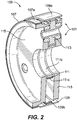
Fig. 2 is a perspective cross-sectional view of the embodiment ofFig. 1 ; -
Fig. 3 is a plan view of the gear assembly of the embodiment ofFig. 1 ; -
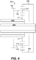
Fig. 4 is a schematic representation of the embodiment ofFig. 1 , showing connected to a coaxial spool inputs; -
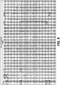
Fig. 5 is a chart of low pressure spool power extraction as a function of both low pressure spool input speed (N1 speed) and high pressure spool input speed (N2 speed); -
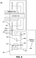
Fig. 6 is a schematic view of an embodiment of a transmission system in accordance with this disclosure; and -
Fig. 7 is a schematic view of another embodiment of a transmission system in accordance with this disclosure. - Reference will now be made to the drawings wherein like reference numerals identify similar structural features or aspects of the subject disclosure. For purposes of explanation and illustration, and not limitation, an illustrative view of an embodiment of a differential in accordance with the disclosure is shown in
Fig. 1 and is designated generally byreference character 100. Other embodiments and/or aspects of this disclosure are shown inFigs. 2-7 . - Referring to
Figs. 1-4 , a turbomachinedual spool differential 100 can include agear assembly 101 configured to combine a low pressure spool input (e.g., input shaft 403) and a high pressure spool input (e.g., input shaft 405) into acombination output 107 to provide an output speed range (e.g., about 3:1 maximum) smaller than a low-spool speed range (e.g., about 10:1 maximum). In certain embodiments, thegear assembly 101 can include aring gear 109, asun gear 111, and a plurality ofplanetary gears 113 disposed between thesun gear 111 and thering gear 109 and meshed with thesun gear 111 and thering gear 109. - The
planetary gears 113 can be rotationally connected to acarrier 115. Thecarrier 115 can include two sides, for example, e.g., as shown, that can be connected in any suitable manner (e.g., both sides bolted together) to trap theplanetary gears 113. - In certain embodiments, the
ring gear 109 can be configured to connect to the lowpressure spool input 403 to rotate thering gear 109 with the lowpressure spool input 403, e.g., as shown. Thering gear 109 can include a spline or gear on anouter diameter 109a thereof, for example. Any suitable type of engagement and/or fastener to connect an input to thering gear 109 is contemplated herein. Thering gear 109 can includegear teeth 109b on an inner diameter thereof meshed withgear teeth 113a of theplanetary gears 113. - In certain embodiments, the
sun gear 111 can be configured to be connected to the highpressure spool input 405 to rotate thesun gear 111, e.g., as shown. In certain embodiments, thesun gear 111 can include aninner opening 111a, e.g., defined through thesun gear 111. Thesun gear 111 can include aspline 111b or a gear on an inner diameter thereof, for example. Any suitable type of engagement and/or fastener to connect an input to thesun gear 111 is contemplated herein. Thesun gear 111 can includegear teeth 111c on an outer diameter thereof meshed with thegear teeth 113a of theplanetary gears 113. - As shown in
Fig. 4 , the input shafts (e.g., the high pressure spool and the low pressure spool) can be coaxial and in-line. In other embodiments, the high pressure spool and the low pressure spool can be separately positioned in any suitable manner (e.g., not coaxially). In certain embodiments, the spools can be separated and geared to the transmission, for example, which is connected to the differential 100. - The
carrier 115 can be configured to connect to thecombination output 107 to rotate thecombination output 107 as a function of both of the lowpressure spool input 403 and the highpressure spool input 405. In certain embodiments, thecombination output 107 can be connected to or a part of the carrier 105. The carrier 105 can include aspline 107a or a gear on an outer diameter thereof that is thecombination output 107 or is configured to connect to thecombination output 107. For example, the carrier 105 can extend axially beyond thering gear 109 and can includespline 107a, e.g., as shown. - In certain embodiments, the ring gear to sun gear ratio can be 2.5:1 such that the
gear assembly 101 is configured to convert a 7.1:1 low pressure spool speed range and a 2.2:1 high pressure spool speed range to a 3.6:1 output speed range. Any other suitable gear ratio is contemplated herein. Any suitable output speed range is contemplated herein. - Referring additionally to
Fig. 6 , a turbomachine dualspool transmission system 600 can include atransmission assembly 601 configured to connect to thecombination output 107 of a dual spool differential 100 at atransmission input 603 to be driven by thecombination output 107 to turn atransmission output 605. Thetransmission assembly 601 can be configured to provide a first output gear ratio in a first state and a second output gear ratio in a second state. As shown, thesystem 600 can include thedual spool differential 100, e.g., as described above. - The
transmission assembly 600 can include atransmission ring gear 607, atransmission sun gear 609, and a plurality of transmissionplanetary gears 611 disposed between thetransmission sun gear 609 and thetransmission ring gear 607 and meshed with thetransmission sun gear 609 and thetransmission ring gear 607. The transmissionplanetary gears 611 can be rotationally connected to atransmission carrier 613. Thegears gear assembly 101 of the differential 100). - The
transmission input 603 can be thetransmission carrier 613 or can be connected to thetransmission carrier 613, for example (e.g., gear teeth disposed on an axial extension of thecarrier 613 as shown). Thetransmission output 605 can be thetransmission ring gear 607 or can be connected to thetransmission ring gear 607. Thetransmission sun gear 609 can be grounded, e.g., to a ground 615 (e.g., an engine housing) such that thetransmission sun gear 609 does not rotate. - The
system 100 can include a clutch 617 configured to selectively engage thetransmission carrier 613 and thetransmission ring gear 607 together. For example, in the first state, the clutch 617 can be disengaged such that thetransmission carrier 613 can rotate relative to thetransmission ring gear 607 and such that thetransmission ring gear 601 is rotated by theplanetary gears 611 in accordance with the first gear ratio (the ratio defined by the relationship ofgears sun gear 609 is fixed, e.g., as shown, thecarrier 613 will drive the planetary gears to rotate around thesun gear 609. - In the second state, the clutch 617 can be engaged such that the
transmission carrier 613 is fixed to thetransmission ring gear 607 and directly rotates thetransmission ring gear 607 in accordance with the second gear ratio. For example, thetransmission carrier 613 can include atransmission input gear 603a meshed with anoutput gear 107a of thecombination output 107, the ratio of which can define the second gear ratio. - In accordance with at least one aspect of this disclosure, a turbomachine (not shown) can include a high pressure spool (e.g., spool input 405) and a low pressure spool (e.g., spool input 403). Any suitable multi-spool turbomachine is contemplated herein as appreciated by those having ordinary skill in the art. The turbomachine can include a turbomachine dual spool differential having a gear assembly as disclosed herein (e.g., 101 as described above) connected to the low pressure spool at a low pressure spool input and the high pressure spool at a high pressure spool input. The turbomachine can include a transmission assembly (e.g., 601) as disclosed herein (e.g., as described above) connected to the dual spool differential.
- In accordance with at least one aspect of this disclosure, a method can include combining a low pressure spool input of a turbomachine and a high pressure spool turbomachine into a combination output to produce a reduced speed range relative to a low pressure spool speed range alone. The method can include maintaining an accessory speed range using a transmission connected to the combination output by selectively switching between a first state having a first gear ratio and a second state having a second gear ratio. The method can include any other suitable method(s) and/or portion(s) thereof.
- As appreciated by those having ordinary skill in the art in accordance with this disclosure, in at least some embodiments of the differential 100, e.g., as shown, regardless of relative speed change between the high pressure spool and the low pressure spool, a smaller speed range than the low pressure spool speed range is always output. However, power extraction from each spool changes based on the absolute speed of the high pressure spool versus the low pressure spool as shown in the chart of
Fig. 5 . - The size of one or more of the gears of the
gear assembly 101 can be changed to achieve a desired speed range and desired power extraction. Referring toFig. 5 , the typical speeds of the low pressure spool input speed (shown as N1 speed) and the high pressure spool input speed (shown as N2 speed) may be a diagonal line from the top left to the bottom right of the chart. However, any suitable speed possibilities for any suitable engine design are contemplated herein. - Power extraction can be shared between the high pressure spool and the low pressure spool, or not. As shown in the chart of
Fig. 5 , low pressure spool power extraction can be about 30% during taxi and/or descent speed settings, and about 55% during takeoff and/or climb and/or cruise speed settings. Embodiments can reduce the output speed range and increase the minimum output speed (e.g., from about 1466 rpm to about 3871 rpm in certain embodiments) to accessories by combining high pressure spool and low pressure spool input speeds to a single output speed. Certain embodiments can provide about 50% output speed range reduction (e.g., 7.1:1 low pressure spool speed range and 2.2:1 high pressure spool speed range converted to a 3.5:1 output speed range) and about a 38% torque reduction at minimum speed. - In certain embodiments, the speed range may still require reduction for certain accessories (e.g., less than 2:1). For example, if the low pressure spool speed range is still greater than a threshold, e.g., 5:1, then a transmission assembly (e.g., 601) may be used to achieve an even smaller speed range. Embodiments of a differential allow use of a simple transmission to further reduce the speed range (e.g., to about 2:1 or less).
- As shown, in certain embodiments, the
transmission carrier 613 is rotated by thecarrier 115 of the differential 101. Thetransmission carrier 615 can be clutched to thetransmission ring gear 607. Opening the clutch can provide a gear ratio (e.g., dependent on gear sizing/teeth of transmission gears) betweendifferential 101 andtransmission output 605, and closing the clutch can make the differential 101 provide power straight through to the transmission output 605 (e.g., a second gear ratio of 1:1 or any other suitable value). - Accordingly, embodiments can take a speed range from one or more embodiments of a dual spool differential and convert it to a speed range that is usable by certain aircraft engine accessories (e.g., a range of 2.2:1 or less, for example). For example, for an output range of 3.6:1 from the differential 101 (e.g., output speed range of about 3871 rpm to about 13756 rpm) and a 1.16:1 differential output gear ratio, and for a first transmission assembly gear ratio R1 of 1.6 (open clutch) and a second transmission assembly gear ratio R1 of 1.0 (closed clutch), the transmission output speed range can be controlled to about 7200 rpm to about 16000 rpm (about 2.2:1). As appreciated by those having ordinary skill in the art in view of this disclosure, ratios can be adjusted to meet required output speeds.
- Referring additionally to
Fig. 7 , a turbomachine dualspool transmission system 700 can include adirect drive assembly 701 configured to selectively allow bypassing of a dual spooldifferential combination output 107 to allow selective direct engagement of a low pressure spool (e.g., input shaft 403) to directly drive a rotational member (e.g.,shaft 703, ring gear 109) or to be directly driven by the rotational member (e.g.,shaft 703, ring gear 109). As shown, the rotational member can includeshaft 703, however, any other suitable member (e.g., an output shaft,ring gear 109 attached to an output shaft) is contemplated herein. - The
system 700 can include thedual spool differential 100a (e.g., differential 100 as disclosed above with any suitable modifications to allow direct bypass of one or more of theinput shafts dual spool differential 100a can be or include any suitable dual spool differential, e.g., as disclosed above. - The
dual spool differential 100a can include a gear assembly, e.g., 101 as disclosed above configured to combine a low pressure spool input and a high pressure spool input into acombination output 107 to provide an output speed range smaller than a low spool speed range alone. The gear assembly can include any suitable gear assembly, e.g., as disclosed above. - The
combination output 107 can be connected to afirst input 705 of thedirect drive assembly 700 to drive the rotational member (e.g., shaft 703). By this connection, in the embodiment shown, the rotational member (e.g., shaft 703) can be driven at the combination output speed which can be a smaller input speed range than the low pressure spool speed range, e.g., as disclosed above. Thefirst input 705 can include afirst input gear 705a meshed with thecombination output gear 107a, and any suitable gear ratio therebetween is contemplated herein. Any other suitable connection is contemplated herein. - In certain embodiments, the
ring gear 109 of thegear assembly 101 can include one or morering gear connections ring gear 109 to rotate with or to be rotated by thering gear 109. Thedirect drive assembly 701 can include one or moredirect drive connections ring gear connections ring gear connections - In certain embodiments, each
direct drive connection direct drive connection shaft 703 as shown). Any other suitable arrangement is contemplated herein. For example, additionally or alternatively toclutches ring gear connections - In certain embodiments, the one or more
ring gear connections first gear 713a and asecond gear 713b. The one or moredirect drive connections third gear 715a and afourth gear 715b. Thefirst gear 713a can be meshed with thethird gear 715a to provide a first gear ratio between thering gear 109 and the rotational member (e.g., the shaft 703). Thesecond gear 713b can be meshed with thefourth gear 715b to provide a second gear ratio between the ring gear 709 and therotational member 703. In certain embodiments, thefourth gear 715b can be larger than thethird gear 715a to provide a low speed gear ratio through the first andthird gears fourth gears - The
first input 705 of thedirect drive assembly 700 can be mounted to the rotational member (e.g., shaft 703) via an overrunning clutch 717 such that thefirst input 705 can rotate relative to the rotational member (e.g., shaft 703) when the one or moredirect drive connections combination output 107 can drivefirst input 705 when each clutch 711a, 711b (e.g., both ofclutches - The system can include a
transmission assembly 600a having atransmission input 613a connected to the rotational member (e.g., shaft 703) of thedirect drive assembly 700. Thetransmission 600a can be connected in any other suitable manner (e.g., additionally or alternatively such that thetransmission ring gear 607 is the rotational member andring gear 109 can directly drivetransmission ring gear 607 when engaged by a clutch). Thetransmission assembly 600a can be configured to provide a first output gear ratio in a first state and a second output gear ratio in a second state. - In certain embodiments, the
transmission gear assembly 600a can be the same or similar to thetransmission gear assembly 600 disclosed above. Thetransmission assembly 600a can include any suitable transmission assembly, e.g., as disclosed herein or otherwise. As shown, thetransmission input 613a can be the transmission carrier or can be connected to the transmission carrier such that the rotational member (e.g., shaft 703) of thedirect drive assembly 700 rotates the carrier of thetransmission assembly 600a. In certain embodiments, thetransmission output 605 can be thetransmission ring gear 607 or can be connected to thetransmission ring gear 607 in any suitable manner. - As shown, the
transmission assembly 600a can include atransmission clutch 617, e.g., as disclosed above. Thetransmission clutch 617 can be configured to selectively engage thetransmission input 613a, e.g., the carrier, as disclosed above. - Embodiments include several possible options to generate a desired output. For example, when all
clutches shaft 703 to be turned by thecombination output 107. When one of theclutches shaft 703 speed will cause the overrunning clutch 717 to disengage from theshaft 703 such thatshaft 703 is disengaged from thecombination output 107. When at least one clutch 711a, 711b is engaged, a low pressure spool (e.g., input shaft 403) can drive an output directly (e.g., either an output from thedirect drive assembly 700 or an output of atransmission 600a connected to the direct drive assembly 700). Any suitable direct drive connection is contemplated herein. - In certain embodiments, the
system 700 can be configured to output a speed range of about 2.2:1 when being used in a direct drive mode such that a first low pressure spool speed range of 1466-3258 (e.g., during idle, taxi, or descent) can be converted to an output speed range of 7200-16000 rpm (e.g., when the first clutch 711a is engaged). A second low pressure spool speed range of 4735-10416 (e.g., during takeoff, climb, or cruise) can also be converted to the output speed range of 7200-16000 rpm (e.g., when the second clutch 711b is engaged). Opening both clutches in the embodiment shown can result in a transitional zone between 3258-4725 rpm, for example, where the combination output drives the transmission which provides shared high pressure spool and low pressure spool power extraction, e.g., as shown inFig. 5 . Any other suitable speed range(s) are contemplated herein. - In accordance with at least one aspect of this disclosure, a turbomachine can include a high pressure spool and a low pressure spool (e.g., any suitable multi-spool turbomachine as appreciated by those having ordinary skill in the art). The turbomachine can include a dual spool differential, e.g., as disclosed herein (e.g., as described above), a direct drive assembly, e.g., as disclosed herein (e.g., as described above), connected to the dual spool differential, and a transmission assembly e.g., as disclosed herein (e.g., as described above), connected to the direct drive assembly at a transmission input to be driven by the combination output to turn a transmission output. Any other suitable arrangement is contemplated herein.
- In accordance with at least one aspect of this disclosure, a method can include engaging a first clutch to directly drive a rotational member of a direct drive assembly and to bypass a combination output of a differential assembly to provide an output within a desired speed range at low engine speeds. The method can include disengaging the first clutch and engaging a second clutch to directly drive the rotational member of the direct drive assembly and to bypass the combination output of a differential assembly to provide the output within the desired speed range at high engine speeds. The method can include any other suitable method(s) and/or portion(s) thereof.
- Any method and/or portion thereof can be embodied using any suitable computer software and/or hardware, and can be executed by any suitable controller. For example, a controller can be connected to each of the clutches to control a state thereof (e.g., engaged or disengaged), e.g., as a function of output speed to maintain speed within a desired speed range. The controller can control the direct drive assembly and/or transmission as a function aircraft flight phase (e.g., to utilize direct drive during low engine speeds such as taxi and descent).
- Embodiments can include a dual spool differential used as an input to a small, lightweight and simple transmission to drive aircraft engine accessories, for example. The transmission input can be on the transmission carrier from the differential carrier. A grounded sun gear can provide a speed-trimming function to adjust the speed of the planet gears that are mounted in the carrier. The planet gears can mesh with the sun gear and ring gear which causes a rotation of the ring gear. The output of the transmission can be connected to the ring gear which drives the accessories, for example. A clutch between the carrier and ring gear can allow for straight-through operation. Embodiments allow for the output speed to be easily set by adjusting the gear ratios of the transmission, for example.
- Certain embodiments include an epicyclic differential with high pressure spool and low pressure spool inputs that produces a smaller output speed range than the low pressure spool alone. The output of the differential can drive one or more aircraft and/or engine accessories (e.g., a generator). The output speed range ratio can be controlled by adjusting the differential parameters, for example.
- Extracting power from the low pressure spool can allow for the high pressure spool to be made more efficient while also allowing for a lower idle speed which decreases brake wear. Embodiments can increase the minimum output speed which reduces the low speed torque. The reduced output speed range can simplify the size and configuration of a downstream transmission (e.g., a variable speed transmission) associated with the engine, for example. In certain embodiments, the downstream transmission can be eliminated entirely if the speed range is small enough, e.g., about 5:1.
- Low spool power extraction can improve engine efficiency and stability, and can reduce brake wear during taxi. Embodiments can reduce maximum torque through the transmission as well.
- Certain embodiments allow 100% low pressure spool power extraction during any and all stages of flight as desired. Embodiments can also allow for electric boost to the low pressure spool from an electric motor (e.g., connected to the direct drive assembly to drive the low pressure spool when directly engaged). For example, a motor/generator can be connected to transmission output and can drive the low pressure spool when directly engaged (e.g., and a controllable clutch for
clutch 717 can be used instead of an overrunning clutch such that it can be disengaged when running the motor/generator). In certain embodiments, a first low speed direct drive feature connects the low spool to the accessory through a first gear mesh and first clutch, and a second high speed direct drive feature connects the low spool to the accessory through a second gear mesh and second clutch. One or more embodiments of a dual spool differential can still be utilized in certain embodiments for intermediate/transitional speeds where use of only the low pressure spool is outside of a desired speed range. - Those having ordinary skill in the art understand that any numerical values disclosed herein can be exact values or can be values within a range. Further, any terms of approximation (e.g., "about", "approximately", "around") used in this disclosure can mean the stated value within a range. For example, in certain embodiments, the range can be within (plus or minus) 20%, or within 10%, or within 5%, or within 2%, or within any other suitable percentage or number as appreciated by those having ordinary skill in the art (e.g., for known tolerance limits or error ranges).
- The articles "a", "an", and "the" as used herein and in the appended claims are used herein to refer to one or to more than one (i.e., to at least one) of the grammatical object of the article unless the context clearly indicates otherwise. By way of example, "an element" means one element or more than one element.
- The phrase "and/or," as used herein in the specification and in the claims, should be understood to mean "either or both" of the elements so conjoined, i.e., elements that are conjunctively present in some cases and disjunctively present in other cases. Multiple elements listed with "and/or" should be construed in the same fashion, i.e., "one or more" of the elements so conjoined. Other elements may optionally be present other than the elements specifically identified by the "and/or" clause, whether related or unrelated to those elements specifically identified. Thus, as a non-limiting example, a reference to "A and/or B", when used in conjunction with open-ended language such as "comprising" can refer, in one embodiment, to A only (optionally including elements other than B); in another embodiment, to B only (optionally including elements other than A); in yet another embodiment, to both A and B (optionally including other elements); etc.
- As used herein in the specification and in the claims, "or" should be understood to have the same meaning as "and/or" as defined above. For example, when separating items in a list, "or" or "and/or" shall be interpreted as being inclusive, i.e., the inclusion of at least one, but also including more than one, of a number or list of elements, and, optionally, additional unlisted items. Only terms clearly indicated to the contrary, such as "only one of' or "exactly one of," or, when used in the claims, "consisting of," will refer to the inclusion of exactly one element of a number or list of elements. In general, the term "or" as used herein shall only be interpreted as indicating exclusive alternatives (i.e., "one or the other but not both") when preceded by terms of exclusivity, such as "either," "one of," "only one of," or "exactly one of."
- Any suitable combination(s) of any disclosed embodiments and/or any suitable portion(s) thereof are contemplated herein as appreciated by those having ordinary skill in the art in view of this disclosure.
- The embodiments of the present disclosure, as described above and shown in the drawings, provide for improvement in the art to which they pertain. While the subject disclosure includes reference to certain embodiments, those skilled in the art will readily appreciate that changes and/or modifications may be made thereto without departing from the scope of the subject disclosure as defined by the claims.
Claims (15)
- A turbomachine dual spool transmission system (700), comprising:
a direct drive assembly (701) configured to selectively allow bypassing of a dual spool differential combination output (107) to allow selective direct engagement of a low pressure spool (LS) to directly drive a rotational member (703; 109) or to be directly driven by the rotational member. - The system of claim 1, further comprising the dual spool differential, wherein the dual spool differential includes a gear assembly configured to combine a low pressure spool input and a high pressure spool input into a combination output to provide an output speed range smaller than a low pressure speed range alone, wherein the combination output is connected to a first input of the direct drive assembly to drive the rotational member.
- The system of claim 2, wherein the gear assembly includes a ring gear, a sun gear, and a plurality of planetary gears disposed between the sun gear and the ring gear and meshed with the sun gear and the ring gear, wherein the planetary gears are rotationally connected to a carrier; optionally wherein the ring gear is configured to connect to the low pressure spool input to rotate the ring gear with the low pressure spool input.
- The system of claim 3, wherein the ring gear includes one or more ring gear connections extending from and/or connected to the ring gear to rotate with or to be rotated by the ring gear.
- The system of claim 4, wherein the direct drive assembly includes one or more direct drive connections connected to or meshed with to the one or more ring gear connections to move with the one or more ring gear connections.
- The system of claim 5, wherein each direct drive connection is mounted to the rotational member by a respective clutch to selectively engage each direct drive connection to the rotational member; optionally wherein the first input of the direct drive assembly is mounted to the rotational member via an overrunning clutch such that the first input can rotate relative to the rotational member when the one direct drive connections is engaged by a respective clutch, and such that the combination output can drive the first input when each clutch is disengaged.
- The system of claim 5 or 6, wherein the one or more ring gear connections include a first gear and a second gear, wherein the one or more direct drive connections include a third gear and a fourth gear, wherein the first gear is meshed with the third gear to provide a first gear ratio between the ring gear and the rotational member, and wherein the second gear is meshed with the fourth gear to provide a second gear ratio between the ring gear and the rotational member; optionally wherein the fourth gear is larger than the third gear to provide a low speed gear ratio through the first and third gears, and a high speed gear ratio through the second and fourth gears.
- The system of any preceding claim, further comprising a transmission assembly having a transmission input connected to the rotational member of the direct drive assembly, wherein the transmission assembly is configured to provide a first output gear ratio in a first state and a second output gear ratio in a second state.
- The system of claim 8, wherein the transmission assembly includes a transmission ring gear, a transmission sun gear, and a plurality of transmission planetary gears disposed between the transmission sun gear and the transmission ring gear and meshed with the transmission sun gear and the transmission ring gear, wherein the transmission planetary gears are rotationally connected to a transmission carrier.
- The system of claim 9, wherein the transmission input is the transmission carrier or is connected to the transmission carrier such that the rotational member of the direct drive assembly rotates the carrier of the transmission assembly.
- The system of claim 9 or 10, wherein the transmission output is the transmission ring gear or is connected to the transmission ring gear; and/or wherein the transmission sun gear is grounded such that the transmission sun gear does not rotate.
- The system of claim 9, 10, or 11, wherein the transmission assembly further includes a clutch configured to selectively engage the transmission carrier and the transmission ring gear.
- The system of claim 12, wherein, in the first state, the clutch is disengaged such that the transmission carrier can rotate relative to the transmission ring gear, and such that the transmission ring gear is rotated by the planetary gears in accordance with the first output gear ratio, and wherein, in the second state, the clutch is engaged such that the transmission carrier is fixed to the transmission ring gear and directly rotates the transmission ring gear in accordance with the second gear ratio; optionally wherein the system is configured to output a speed range of about 2.2:1 when being used in a direct drive mode such that a first low pressure spool speed range of 1466-3258 can be converted to an output speed range of 7200-16000 rpm and such that a second low pressure spool speed range of 4735-10416 can also be converted to the output speed range of 7200-16000 rpm.
- A turbomachine, comprising:a high pressure spool (HS);a low pressure spool (LS); anda dual spool differential (100; 100a) comprising a gear assembly (101) connected to the low pressure spool at a low pressure spool input (403) and the high pressure spool at a high pressure spool input (405), the gear assembly configured to combine the low pressure spool input and the high pressure spool input into a combination output to provide an output speed range smaller than a low pressure speed range alone;a direct drive assembly (701) configured to selectively allow bypassing of the combination output to allow selective direct engagement of a low pressure spool to directly drive a rotational member (703; 109) or to be directly driven by the rotational member; anda transmission assembly (601) connected to the direct drive assembly at a transmission input to be driven by the combination output to turn a transmission output (605), the transmission configured to provide a first output gear ratio in a first state and a second output gear ratio in a second state.
- A method, comprising:engaging a first clutch (711a) to directly drive a rotational member (703; 109) of a direct drive assembly (701) and to bypass a combination output of a differential assembly to provide an output within a desired speed range at low engine speeds;disengaging the first clutch and engaging a second clutch (711b) to directly drive the rotational member of the direct drive assembly and to bypass the combination output of a differential assembly to provide the output within the desired speed range at high engine speeds.
Applications Claiming Priority (1)
| Application Number | Priority Date | Filing Date | Title |
|---|---|---|---|
| US16/536,938 US10961917B2 (en) | 2019-08-09 | 2019-08-09 | Turbomachine dual spool transmission systems |
Publications (2)
| Publication Number | Publication Date |
|---|---|
| EP3772578A1 true EP3772578A1 (en) | 2021-02-10 |
| EP3772578B1 EP3772578B1 (en) | 2024-04-24 |
Family
ID=68916443
Family Applications (1)
| Application Number | Title | Priority Date | Filing Date |
|---|---|---|---|
| EP19216084.4A Active EP3772578B1 (en) | 2019-08-09 | 2019-12-13 | Turbomachine dual spool transmission systems |
Country Status (2)
| Country | Link |
|---|---|
| US (1) | US10961917B2 (en) |
| EP (1) | EP3772578B1 (en) |
Families Citing this family (2)
| Publication number | Priority date | Publication date | Assignee | Title |
|---|---|---|---|---|
| GB201913195D0 (en) * | 2019-09-12 | 2019-10-30 | Rolls Royce Plc | Gas turbine engine |
| US20260110266A1 (en) * | 2024-10-22 | 2026-04-23 | The Boeing Company | Transfer Assembly to Transfer Mechanical Power During Operation of a Turbine Engine |
Citations (3)
| Publication number | Priority date | Publication date | Assignee | Title |
|---|---|---|---|---|
| DE19627407A1 (en) * | 1996-07-06 | 1998-01-08 | Zahnradfabrik Friedrichshafen | Continuously variable belted transmission e.g. for tractors and working machines |
| WO2008044972A1 (en) * | 2006-10-13 | 2008-04-17 | Volvo Aero Corporation | A device for retrieval of power from a gas turbine engine, and a gas turbine engine |
| US20170328453A1 (en) * | 2014-04-09 | 2017-11-16 | Deere & Company | Multi-mode powertrains |
Family Cites Families (14)
| Publication number | Priority date | Publication date | Assignee | Title |
|---|---|---|---|---|
| GB2229237B (en) * | 1989-03-14 | 1993-01-20 | Rolls Royce Plc | Differential gear assembly |
| FR2863312B1 (en) * | 2003-12-09 | 2008-07-04 | Snecma Moteurs | DOUBLE-BODY TURBOREACTOR WITH MEANS FOR DRIVING ACCESSORY MACHINES |
| US7788898B2 (en) | 2006-12-06 | 2010-09-07 | General Electric Company | Variable coupling of turbofan engine spools via open differential gear set or simple planetary gear set for improved power extraction and engine operability, with torque coupling for added flexibility |
| WO2008082336A1 (en) | 2006-12-29 | 2008-07-10 | Volvo Aero Corporation | A power transmission device for a gas turbine engine, an aeroplane and a method for operating a gas turbine engine |
| FR2915523A1 (en) | 2007-04-27 | 2008-10-31 | Snecma Sa | DEVICE FOR GENERATING ELECTRIC ENERGY IN A DOUBLE-BODY GAS TURBINE ENGINE |
| CN101451596B (en) * | 2007-12-04 | 2012-01-11 | 艾晓林 | Bimodule type electromechanical non-stage transmission |
| FR2972765B1 (en) | 2011-03-17 | 2013-04-05 | Messier Dowty | METHOD FOR OPTIMIZING DOUBLE-BODY TURBOREACTOR BLOWER SPEED AND IMPLEMENTATION ARCHITECTURE |
| US20130247539A1 (en) | 2012-03-26 | 2013-09-26 | Richard John Hoppe | Multi-shaft power extraction from gas turbine engine |
| WO2015073084A1 (en) | 2013-08-20 | 2015-05-21 | The Regents Of The University Of Colorado, A Body Corporate | Hybrid co-axial shaft in shaft transmission using planetary gear set for multiple sources of torque |
| US9347373B2 (en) * | 2013-12-19 | 2016-05-24 | Pratt & Whitney Canada Corp. | Gas turbine engine with transmission |
| US9944163B2 (en) * | 2014-04-09 | 2018-04-17 | Deere & Company | Multi-mode power trains |
| US10273883B2 (en) | 2016-02-26 | 2019-04-30 | The Boeing Company | Engine accessory drives systems and methods |
| US10526975B2 (en) | 2016-11-30 | 2020-01-07 | The Boeing Company | Power extraction system and method for a gas turbine engine of a vehicle |
| KR102651619B1 (en) * | 2016-12-01 | 2024-03-25 | 현대자동차주식회사 | Hybrid powertrain for vehicle |
-
2019
- 2019-08-09 US US16/536,938 patent/US10961917B2/en active Active
- 2019-12-13 EP EP19216084.4A patent/EP3772578B1/en active Active
Patent Citations (3)
| Publication number | Priority date | Publication date | Assignee | Title |
|---|---|---|---|---|
| DE19627407A1 (en) * | 1996-07-06 | 1998-01-08 | Zahnradfabrik Friedrichshafen | Continuously variable belted transmission e.g. for tractors and working machines |
| WO2008044972A1 (en) * | 2006-10-13 | 2008-04-17 | Volvo Aero Corporation | A device for retrieval of power from a gas turbine engine, and a gas turbine engine |
| US20170328453A1 (en) * | 2014-04-09 | 2017-11-16 | Deere & Company | Multi-mode powertrains |
Also Published As
| Publication number | Publication date |
|---|---|
| US10961917B2 (en) | 2021-03-30 |
| US20210040893A1 (en) | 2021-02-11 |
| EP3772578B1 (en) | 2024-04-24 |
Similar Documents
| Publication | Publication Date | Title |
|---|---|---|
| EP3351825B1 (en) | Low speed spool generator transmission | |
| US11015522B2 (en) | Gearbox for gas turbine engine | |
| CA2612030C (en) | Variable coupling of turbofan engine spools via open differential or planetary gear set with torque coupling for power extraction and engine operability | |
| EP2226487B1 (en) | Variable drive gas turbine engine | |
| CA2863923C (en) | Gas turbine engine with transmission | |
| CN204383158U (en) | The hybrid drive of self-propelled vehicle | |
| EP0716947B1 (en) | Hybrid power transmission | |
| US10759268B2 (en) | Manual gearbox section for a vehicle, vehicle including the manual gearbox section, and method for shifting the manual gearbox section | |
| US7044877B2 (en) | Two speed transmission with smooth power shift | |
| US20080113847A1 (en) | Shift Control Method For An Automatic Gearbox | |
| JP4548622B2 (en) | Hybrid gearbox | |
| EP3772577B1 (en) | Turbomachine dual spool transmission systems | |
| US20190218969A1 (en) | Aircraft turbine engine with epicyclic reduction gear having a variable reduction ratio | |
| CN104755806A (en) | Transmissions for speed change transmissions | |
| EP3772578B1 (en) | Turbomachine dual spool transmission systems | |
| WO2009067048A1 (en) | Gas turbine engine | |
| JP2019529838A (en) | Multi-speed transmission | |
| CN110539744A (en) | Low-speed driving mode switching control method for power split type hybrid vehicle | |
| EP3267013B1 (en) | Gas turbine engine starter reduction gear train with jacking and planetary geared transmission | |
| US11713720B2 (en) | Turbomachine dual spool transmission systems | |
| US11255273B2 (en) | Turbomachine dual spool transmission systems | |
| GB2550934A (en) | Gear train for a vehicle | |
| WO2017108353A1 (en) | A transmission system for a vehicle | |
| US20070265132A1 (en) | Transmission Device For an Auxiliary or Accessory of a Variable-Speed Engine, an Engine Equipped Therewith and Uses Thereof |
Legal Events
| Date | Code | Title | Description |
|---|---|---|---|
| PUAI | Public reference made under article 153(3) epc to a published international application that has entered the european phase |
Free format text: ORIGINAL CODE: 0009012 |
|
| STAA | Information on the status of an ep patent application or granted ep patent |
Free format text: STATUS: THE APPLICATION HAS BEEN PUBLISHED |
|
| AK | Designated contracting states |
Kind code of ref document: A1 Designated state(s): AL AT BE BG CH CY CZ DE DK EE ES FI FR GB GR HR HU IE IS IT LI LT LU LV MC MK MT NL NO PL PT RO RS SE SI SK SM TR |
|
| AX | Request for extension of the european patent |
Extension state: BA ME |
|
| STAA | Information on the status of an ep patent application or granted ep patent |
Free format text: STATUS: REQUEST FOR EXAMINATION WAS MADE |
|
| 17P | Request for examination filed |
Effective date: 20210810 |
|
| RBV | Designated contracting states (corrected) |
Designated state(s): AL AT BE BG CH CY CZ DE DK EE ES FI FR GB GR HR HU IE IS IT LI LT LU LV MC MK MT NL NO PL PT RO RS SE SI SK SM TR |
|
| STAA | Information on the status of an ep patent application or granted ep patent |
Free format text: STATUS: EXAMINATION IS IN PROGRESS |
|
| 17Q | First examination report despatched |
Effective date: 20220225 |
|
| GRAP | Despatch of communication of intention to grant a patent |
Free format text: ORIGINAL CODE: EPIDOSNIGR1 |
|
| STAA | Information on the status of an ep patent application or granted ep patent |
Free format text: STATUS: GRANT OF PATENT IS INTENDED |
|
| RIC1 | Information provided on ipc code assigned before grant |
Ipc: F16H 3/54 20060101ALN20230117BHEP Ipc: F16H 37/08 20060101ALI20230117BHEP Ipc: F02C 7/36 20060101ALI20230117BHEP Ipc: F02C 3/113 20060101AFI20230117BHEP |
|
| INTG | Intention to grant announced |
Effective date: 20230207 |
|
| GRAJ | Information related to disapproval of communication of intention to grant by the applicant or resumption of examination proceedings by the epo deleted |
Free format text: ORIGINAL CODE: EPIDOSDIGR1 |
|
| STAA | Information on the status of an ep patent application or granted ep patent |
Free format text: STATUS: EXAMINATION IS IN PROGRESS |
|
| INTC | Intention to grant announced (deleted) | ||
| GRAP | Despatch of communication of intention to grant a patent |
Free format text: ORIGINAL CODE: EPIDOSNIGR1 |
|
| STAA | Information on the status of an ep patent application or granted ep patent |
Free format text: STATUS: GRANT OF PATENT IS INTENDED |
|
| RIC1 | Information provided on ipc code assigned before grant |
Ipc: F16H 3/54 20060101ALN20231208BHEP Ipc: F16H 37/08 20060101ALI20231208BHEP Ipc: F02C 7/36 20060101ALI20231208BHEP Ipc: F02C 3/113 20060101AFI20231208BHEP |
|
| INTG | Intention to grant announced |
Effective date: 20240102 |
|
| GRAS | Grant fee paid |
Free format text: ORIGINAL CODE: EPIDOSNIGR3 |
|
| GRAA | (expected) grant |
Free format text: ORIGINAL CODE: 0009210 |
|
| STAA | Information on the status of an ep patent application or granted ep patent |
Free format text: STATUS: THE PATENT HAS BEEN GRANTED |
|
| AK | Designated contracting states |
Kind code of ref document: B1 Designated state(s): AL AT BE BG CH CY CZ DE DK EE ES FI FR GB GR HR HU IE IS IT LI LT LU LV MC MK MT NL NO PL PT RO RS SE SI SK SM TR |
|
| REG | Reference to a national code |
Ref country code: GB Ref legal event code: FG4D |
|
| REG | Reference to a national code |
Ref country code: CH Ref legal event code: EP |
|
| REG | Reference to a national code |
Ref country code: DE Ref legal event code: R096 Ref document number: 602019050798 Country of ref document: DE |
|
| REG | Reference to a national code |
Ref country code: IE Ref legal event code: FG4D |
|
| REG | Reference to a national code |
Ref country code: LT Ref legal event code: MG9D |
|
| REG | Reference to a national code |
Ref country code: NL Ref legal event code: MP Effective date: 20240424 |
|
| REG | Reference to a national code |
Ref country code: AT Ref legal event code: MK05 Ref document number: 1679804 Country of ref document: AT Kind code of ref document: T Effective date: 20240424 |
|
| PG25 | Lapsed in a contracting state [announced via postgrant information from national office to epo] |
Ref country code: NL Free format text: LAPSE BECAUSE OF FAILURE TO SUBMIT A TRANSLATION OF THE DESCRIPTION OR TO PAY THE FEE WITHIN THE PRESCRIBED TIME-LIMIT Effective date: 20240424 |
|
| PG25 | Lapsed in a contracting state [announced via postgrant information from national office to epo] |
Ref country code: NL Free format text: LAPSE BECAUSE OF FAILURE TO SUBMIT A TRANSLATION OF THE DESCRIPTION OR TO PAY THE FEE WITHIN THE PRESCRIBED TIME-LIMIT Effective date: 20240424 |
|
| PG25 | Lapsed in a contracting state [announced via postgrant information from national office to epo] |
Ref country code: IS Free format text: LAPSE BECAUSE OF FAILURE TO SUBMIT A TRANSLATION OF THE DESCRIPTION OR TO PAY THE FEE WITHIN THE PRESCRIBED TIME-LIMIT Effective date: 20240824 |
|
| PG25 | Lapsed in a contracting state [announced via postgrant information from national office to epo] |
Ref country code: BG Free format text: LAPSE BECAUSE OF FAILURE TO SUBMIT A TRANSLATION OF THE DESCRIPTION OR TO PAY THE FEE WITHIN THE PRESCRIBED TIME-LIMIT Effective date: 20240424 |
|
| PG25 | Lapsed in a contracting state [announced via postgrant information from national office to epo] |
Ref country code: HR Free format text: LAPSE BECAUSE OF FAILURE TO SUBMIT A TRANSLATION OF THE DESCRIPTION OR TO PAY THE FEE WITHIN THE PRESCRIBED TIME-LIMIT Effective date: 20240424 Ref country code: FI Free format text: LAPSE BECAUSE OF FAILURE TO SUBMIT A TRANSLATION OF THE DESCRIPTION OR TO PAY THE FEE WITHIN THE PRESCRIBED TIME-LIMIT Effective date: 20240424 |
|
| PG25 | Lapsed in a contracting state [announced via postgrant information from national office to epo] |
Ref country code: GR Free format text: LAPSE BECAUSE OF FAILURE TO SUBMIT A TRANSLATION OF THE DESCRIPTION OR TO PAY THE FEE WITHIN THE PRESCRIBED TIME-LIMIT Effective date: 20240725 |
|
| PG25 | Lapsed in a contracting state [announced via postgrant information from national office to epo] |
Ref country code: PT Free format text: LAPSE BECAUSE OF FAILURE TO SUBMIT A TRANSLATION OF THE DESCRIPTION OR TO PAY THE FEE WITHIN THE PRESCRIBED TIME-LIMIT Effective date: 20240826 |
|
| PG25 | Lapsed in a contracting state [announced via postgrant information from national office to epo] |
Ref country code: ES Free format text: LAPSE BECAUSE OF FAILURE TO SUBMIT A TRANSLATION OF THE DESCRIPTION OR TO PAY THE FEE WITHIN THE PRESCRIBED TIME-LIMIT Effective date: 20240424 |
|
| PG25 | Lapsed in a contracting state [announced via postgrant information from national office to epo] |
Ref country code: AT Free format text: LAPSE BECAUSE OF FAILURE TO SUBMIT A TRANSLATION OF THE DESCRIPTION OR TO PAY THE FEE WITHIN THE PRESCRIBED TIME-LIMIT Effective date: 20240424 |
|
| PG25 | Lapsed in a contracting state [announced via postgrant information from national office to epo] |
Ref country code: PL Free format text: LAPSE BECAUSE OF FAILURE TO SUBMIT A TRANSLATION OF THE DESCRIPTION OR TO PAY THE FEE WITHIN THE PRESCRIBED TIME-LIMIT Effective date: 20240424 |
|
| PG25 | Lapsed in a contracting state [announced via postgrant information from national office to epo] |
Ref country code: LV Free format text: LAPSE BECAUSE OF FAILURE TO SUBMIT A TRANSLATION OF THE DESCRIPTION OR TO PAY THE FEE WITHIN THE PRESCRIBED TIME-LIMIT Effective date: 20240424 |
|
| PG25 | Lapsed in a contracting state [announced via postgrant information from national office to epo] |
Ref country code: PT Free format text: LAPSE BECAUSE OF FAILURE TO SUBMIT A TRANSLATION OF THE DESCRIPTION OR TO PAY THE FEE WITHIN THE PRESCRIBED TIME-LIMIT Effective date: 20240826 Ref country code: PL Free format text: LAPSE BECAUSE OF FAILURE TO SUBMIT A TRANSLATION OF THE DESCRIPTION OR TO PAY THE FEE WITHIN THE PRESCRIBED TIME-LIMIT Effective date: 20240424 Ref country code: NO Free format text: LAPSE BECAUSE OF FAILURE TO SUBMIT A TRANSLATION OF THE DESCRIPTION OR TO PAY THE FEE WITHIN THE PRESCRIBED TIME-LIMIT Effective date: 20240724 Ref country code: LV Free format text: LAPSE BECAUSE OF FAILURE TO SUBMIT A TRANSLATION OF THE DESCRIPTION OR TO PAY THE FEE WITHIN THE PRESCRIBED TIME-LIMIT Effective date: 20240424 Ref country code: IS Free format text: LAPSE BECAUSE OF FAILURE TO SUBMIT A TRANSLATION OF THE DESCRIPTION OR TO PAY THE FEE WITHIN THE PRESCRIBED TIME-LIMIT Effective date: 20240824 Ref country code: HR Free format text: LAPSE BECAUSE OF FAILURE TO SUBMIT A TRANSLATION OF THE DESCRIPTION OR TO PAY THE FEE WITHIN THE PRESCRIBED TIME-LIMIT Effective date: 20240424 Ref country code: GR Free format text: LAPSE BECAUSE OF FAILURE TO SUBMIT A TRANSLATION OF THE DESCRIPTION OR TO PAY THE FEE WITHIN THE PRESCRIBED TIME-LIMIT Effective date: 20240725 Ref country code: FI Free format text: LAPSE BECAUSE OF FAILURE TO SUBMIT A TRANSLATION OF THE DESCRIPTION OR TO PAY THE FEE WITHIN THE PRESCRIBED TIME-LIMIT Effective date: 20240424 Ref country code: ES Free format text: LAPSE BECAUSE OF FAILURE TO SUBMIT A TRANSLATION OF THE DESCRIPTION OR TO PAY THE FEE WITHIN THE PRESCRIBED TIME-LIMIT Effective date: 20240424 Ref country code: BG Free format text: LAPSE BECAUSE OF FAILURE TO SUBMIT A TRANSLATION OF THE DESCRIPTION OR TO PAY THE FEE WITHIN THE PRESCRIBED TIME-LIMIT Effective date: 20240424 Ref country code: AT Free format text: LAPSE BECAUSE OF FAILURE TO SUBMIT A TRANSLATION OF THE DESCRIPTION OR TO PAY THE FEE WITHIN THE PRESCRIBED TIME-LIMIT Effective date: 20240424 Ref country code: RS Free format text: LAPSE BECAUSE OF FAILURE TO SUBMIT A TRANSLATION OF THE DESCRIPTION OR TO PAY THE FEE WITHIN THE PRESCRIBED TIME-LIMIT Effective date: 20240724 |
|
| PG25 | Lapsed in a contracting state [announced via postgrant information from national office to epo] |
Ref country code: DK Free format text: LAPSE BECAUSE OF FAILURE TO SUBMIT A TRANSLATION OF THE DESCRIPTION OR TO PAY THE FEE WITHIN THE PRESCRIBED TIME-LIMIT Effective date: 20240424 |
|
| PG25 | Lapsed in a contracting state [announced via postgrant information from national office to epo] |
Ref country code: EE Free format text: LAPSE BECAUSE OF FAILURE TO SUBMIT A TRANSLATION OF THE DESCRIPTION OR TO PAY THE FEE WITHIN THE PRESCRIBED TIME-LIMIT Effective date: 20240424 |
|
| PG25 | Lapsed in a contracting state [announced via postgrant information from national office to epo] |
Ref country code: CZ Free format text: LAPSE BECAUSE OF FAILURE TO SUBMIT A TRANSLATION OF THE DESCRIPTION OR TO PAY THE FEE WITHIN THE PRESCRIBED TIME-LIMIT Effective date: 20240424 |
|
| PG25 | Lapsed in a contracting state [announced via postgrant information from national office to epo] |
Ref country code: RO Free format text: LAPSE BECAUSE OF FAILURE TO SUBMIT A TRANSLATION OF THE DESCRIPTION OR TO PAY THE FEE WITHIN THE PRESCRIBED TIME-LIMIT Effective date: 20240424 Ref country code: SK Free format text: LAPSE BECAUSE OF FAILURE TO SUBMIT A TRANSLATION OF THE DESCRIPTION OR TO PAY THE FEE WITHIN THE PRESCRIBED TIME-LIMIT Effective date: 20240424 |
|
| REG | Reference to a national code |
Ref country code: DE Ref legal event code: R097 Ref document number: 602019050798 Country of ref document: DE |
|
| PG25 | Lapsed in a contracting state [announced via postgrant information from national office to epo] |
Ref country code: SM Free format text: LAPSE BECAUSE OF FAILURE TO SUBMIT A TRANSLATION OF THE DESCRIPTION OR TO PAY THE FEE WITHIN THE PRESCRIBED TIME-LIMIT Effective date: 20240424 |
|
| PG25 | Lapsed in a contracting state [announced via postgrant information from national office to epo] |
Ref country code: SM Free format text: LAPSE BECAUSE OF FAILURE TO SUBMIT A TRANSLATION OF THE DESCRIPTION OR TO PAY THE FEE WITHIN THE PRESCRIBED TIME-LIMIT Effective date: 20240424 Ref country code: SK Free format text: LAPSE BECAUSE OF FAILURE TO SUBMIT A TRANSLATION OF THE DESCRIPTION OR TO PAY THE FEE WITHIN THE PRESCRIBED TIME-LIMIT Effective date: 20240424 Ref country code: RO Free format text: LAPSE BECAUSE OF FAILURE TO SUBMIT A TRANSLATION OF THE DESCRIPTION OR TO PAY THE FEE WITHIN THE PRESCRIBED TIME-LIMIT Effective date: 20240424 Ref country code: EE Free format text: LAPSE BECAUSE OF FAILURE TO SUBMIT A TRANSLATION OF THE DESCRIPTION OR TO PAY THE FEE WITHIN THE PRESCRIBED TIME-LIMIT Effective date: 20240424 Ref country code: DK Free format text: LAPSE BECAUSE OF FAILURE TO SUBMIT A TRANSLATION OF THE DESCRIPTION OR TO PAY THE FEE WITHIN THE PRESCRIBED TIME-LIMIT Effective date: 20240424 Ref country code: CZ Free format text: LAPSE BECAUSE OF FAILURE TO SUBMIT A TRANSLATION OF THE DESCRIPTION OR TO PAY THE FEE WITHIN THE PRESCRIBED TIME-LIMIT Effective date: 20240424 |
|
| PLBE | No opposition filed within time limit |
Free format text: ORIGINAL CODE: 0009261 |
|
| STAA | Information on the status of an ep patent application or granted ep patent |
Free format text: STATUS: NO OPPOSITION FILED WITHIN TIME LIMIT |
|
| 26N | No opposition filed |
Effective date: 20250127 |
|
| PG25 | Lapsed in a contracting state [announced via postgrant information from national office to epo] |
Ref country code: SI Free format text: LAPSE BECAUSE OF FAILURE TO SUBMIT A TRANSLATION OF THE DESCRIPTION OR TO PAY THE FEE WITHIN THE PRESCRIBED TIME-LIMIT Effective date: 20240424 |
|
| PG25 | Lapsed in a contracting state [announced via postgrant information from national office to epo] |
Ref country code: MC Free format text: LAPSE BECAUSE OF FAILURE TO SUBMIT A TRANSLATION OF THE DESCRIPTION OR TO PAY THE FEE WITHIN THE PRESCRIBED TIME-LIMIT Effective date: 20240424 |
|
| REG | Reference to a national code |
Ref country code: CH Ref legal event code: PL |
|
| PG25 | Lapsed in a contracting state [announced via postgrant information from national office to epo] |
Ref country code: LU Free format text: LAPSE BECAUSE OF NON-PAYMENT OF DUE FEES Effective date: 20241213 |
|
| PG25 | Lapsed in a contracting state [announced via postgrant information from national office to epo] |
Ref country code: SE Free format text: LAPSE BECAUSE OF FAILURE TO SUBMIT A TRANSLATION OF THE DESCRIPTION OR TO PAY THE FEE WITHIN THE PRESCRIBED TIME-LIMIT Effective date: 20240424 |
|
| REG | Reference to a national code |
Ref country code: BE Ref legal event code: MM Effective date: 20241231 |
|
| PG25 | Lapsed in a contracting state [announced via postgrant information from national office to epo] |
Ref country code: BE Free format text: LAPSE BECAUSE OF NON-PAYMENT OF DUE FEES Effective date: 20241231 |
|
| PG25 | Lapsed in a contracting state [announced via postgrant information from national office to epo] |
Ref country code: CH Free format text: LAPSE BECAUSE OF NON-PAYMENT OF DUE FEES Effective date: 20241231 |
|
| PG25 | Lapsed in a contracting state [announced via postgrant information from national office to epo] |
Ref country code: IE Free format text: LAPSE BECAUSE OF NON-PAYMENT OF DUE FEES Effective date: 20241213 |
|
| PGFP | Annual fee paid to national office [announced via postgrant information from national office to epo] |
Ref country code: DE Payment date: 20251126 Year of fee payment: 7 |
|
| PGFP | Annual fee paid to national office [announced via postgrant information from national office to epo] |
Ref country code: GB Payment date: 20251119 Year of fee payment: 7 |
|
| PGFP | Annual fee paid to national office [announced via postgrant information from national office to epo] |
Ref country code: FR Payment date: 20251120 Year of fee payment: 7 |
|
| PG25 | Lapsed in a contracting state [announced via postgrant information from national office to epo] |
Ref country code: IT Free format text: LAPSE BECAUSE OF FAILURE TO SUBMIT A TRANSLATION OF THE DESCRIPTION OR TO PAY THE FEE WITHIN THE PRESCRIBED TIME-LIMIT Effective date: 20240424 |