EP3772482A1 - Auxiliary brake assembly - Google Patents
Auxiliary brake assembly Download PDFInfo
- Publication number
- EP3772482A1 EP3772482A1 EP19214966.4A EP19214966A EP3772482A1 EP 3772482 A1 EP3772482 A1 EP 3772482A1 EP 19214966 A EP19214966 A EP 19214966A EP 3772482 A1 EP3772482 A1 EP 3772482A1
- Authority
- EP
- European Patent Office
- Prior art keywords
- pinion
- fastener
- gear
- auxiliary brake
- coupled
- Prior art date
- Legal status (The legal status is an assumption and is not a legal conclusion. Google has not performed a legal analysis and makes no representation as to the accuracy of the status listed.)
- Granted
Links
Images


Classifications
-
- B—PERFORMING OPERATIONS; TRANSPORTING
- B66—HOISTING; LIFTING; HAULING
- B66D—CAPSTANS; WINCHES; TACKLES, e.g. PULLEY BLOCKS; HOISTS
- B66D5/00—Braking or detent devices characterised by application to lifting or hoisting gear, e.g. for controlling the lowering of loads
- B66D5/02—Crane, lift hoist, or winch brakes operating on drums, barrels, or ropes
- B66D5/12—Crane, lift hoist, or winch brakes operating on drums, barrels, or ropes with axial effect
- B66D5/14—Crane, lift hoist, or winch brakes operating on drums, barrels, or ropes with axial effect embodying discs
-
- B—PERFORMING OPERATIONS; TRANSPORTING
- B66—HOISTING; LIFTING; HAULING
- B66D—CAPSTANS; WINCHES; TACKLES, e.g. PULLEY BLOCKS; HOISTS
- B66D1/00—Rope, cable, or chain winding mechanisms; Capstans
- B66D1/02—Driving gear
- B66D1/14—Power transmissions between power sources and drums or barrels
- B66D1/16—Power transmissions between power sources and drums or barrels the drums or barrels being freely rotatable, e.g. having a clutch activated independently of a brake
-
- B—PERFORMING OPERATIONS; TRANSPORTING
- B66—HOISTING; LIFTING; HAULING
- B66D—CAPSTANS; WINCHES; TACKLES, e.g. PULLEY BLOCKS; HOISTS
- B66D3/00—Portable or mobile lifting or hauling appliances
- B66D3/18—Power-operated hoists
- B66D3/20—Power-operated hoists with driving motor, e.g. electric motor, and drum or barrel contained in a common housing
- B66D3/22—Power-operated hoists with driving motor, e.g. electric motor, and drum or barrel contained in a common housing with variable-speed gearings between driving motor and drum or barrel
-
- B—PERFORMING OPERATIONS; TRANSPORTING
- B66—HOISTING; LIFTING; HAULING
- B66D—CAPSTANS; WINCHES; TACKLES, e.g. PULLEY BLOCKS; HOISTS
- B66D5/00—Braking or detent devices characterised by application to lifting or hoisting gear, e.g. for controlling the lowering of loads
- B66D5/02—Crane, lift hoist, or winch brakes operating on drums, barrels, or ropes
- B66D5/24—Operating devices
- B66D5/30—Operating devices electrical
-
- F—MECHANICAL ENGINEERING; LIGHTING; HEATING; WEAPONS; BLASTING
- F16—ENGINEERING ELEMENTS AND UNITS; GENERAL MEASURES FOR PRODUCING AND MAINTAINING EFFECTIVE FUNCTIONING OF MACHINES OR INSTALLATIONS; THERMAL INSULATION IN GENERAL
- F16D—COUPLINGS FOR TRANSMITTING ROTATION; CLUTCHES; BRAKES
- F16D55/00—Brakes with substantially-radial braking surfaces pressed together in axial direction, e.g. disc brakes
- F16D55/24—Brakes with substantially-radial braking surfaces pressed together in axial direction, e.g. disc brakes with a plurality of axially-movable discs, lamellae, or pads, pressed from one side towards an axially-located member
- F16D55/26—Brakes with substantially-radial braking surfaces pressed together in axial direction, e.g. disc brakes with a plurality of axially-movable discs, lamellae, or pads, pressed from one side towards an axially-located member without self-tightening action
- F16D55/36—Brakes with a plurality of rotating discs all lying side by side
- F16D55/38—Brakes with a plurality of rotating discs all lying side by side mechanically actuated
-
- F—MECHANICAL ENGINEERING; LIGHTING; HEATING; WEAPONS; BLASTING
- F16—ENGINEERING ELEMENTS AND UNITS; GENERAL MEASURES FOR PRODUCING AND MAINTAINING EFFECTIVE FUNCTIONING OF MACHINES OR INSTALLATIONS; THERMAL INSULATION IN GENERAL
- F16D—COUPLINGS FOR TRANSMITTING ROTATION; CLUTCHES; BRAKES
- F16D65/00—Parts or details
- F16D65/14—Actuating mechanisms for brakes; Means for initiating operation at a predetermined position
- F16D65/16—Actuating mechanisms for brakes; Means for initiating operation at a predetermined position arranged in or on the brake
- F16D65/18—Actuating mechanisms for brakes; Means for initiating operation at a predetermined position arranged in or on the brake adapted for drawing members together, e.g. for disc brakes
- F16D65/186—Actuating mechanisms for brakes; Means for initiating operation at a predetermined position arranged in or on the brake adapted for drawing members together, e.g. for disc brakes with full-face force-applying member, e.g. annular
-
- F—MECHANICAL ENGINEERING; LIGHTING; HEATING; WEAPONS; BLASTING
- F16—ENGINEERING ELEMENTS AND UNITS; GENERAL MEASURES FOR PRODUCING AND MAINTAINING EFFECTIVE FUNCTIONING OF MACHINES OR INSTALLATIONS; THERMAL INSULATION IN GENERAL
- F16D—COUPLINGS FOR TRANSMITTING ROTATION; CLUTCHES; BRAKES
- F16D67/00—Combinations of couplings and brakes; Combinations of clutches and brakes
- F16D67/02—Clutch-brake combinations
-
- F—MECHANICAL ENGINEERING; LIGHTING; HEATING; WEAPONS; BLASTING
- F16—ENGINEERING ELEMENTS AND UNITS; GENERAL MEASURES FOR PRODUCING AND MAINTAINING EFFECTIVE FUNCTIONING OF MACHINES OR INSTALLATIONS; THERMAL INSULATION IN GENERAL
- F16D—COUPLINGS FOR TRANSMITTING ROTATION; CLUTCHES; BRAKES
- F16D55/00—Brakes with substantially-radial braking surfaces pressed together in axial direction, e.g. disc brakes
- F16D2055/0004—Parts or details of disc brakes
- F16D2055/0058—Fully lined, i.e. braking surface extending over the entire disc circumference
-
- F—MECHANICAL ENGINEERING; LIGHTING; HEATING; WEAPONS; BLASTING
- F16—ENGINEERING ELEMENTS AND UNITS; GENERAL MEASURES FOR PRODUCING AND MAINTAINING EFFECTIVE FUNCTIONING OF MACHINES OR INSTALLATIONS; THERMAL INSULATION IN GENERAL
- F16D—COUPLINGS FOR TRANSMITTING ROTATION; CLUTCHES; BRAKES
- F16D2121/00—Type of actuator operation force
- F16D2121/18—Electric or magnetic
- F16D2121/24—Electric or magnetic using motors
-
- F—MECHANICAL ENGINEERING; LIGHTING; HEATING; WEAPONS; BLASTING
- F16—ENGINEERING ELEMENTS AND UNITS; GENERAL MEASURES FOR PRODUCING AND MAINTAINING EFFECTIVE FUNCTIONING OF MACHINES OR INSTALLATIONS; THERMAL INSULATION IN GENERAL
- F16D—COUPLINGS FOR TRANSMITTING ROTATION; CLUTCHES; BRAKES
- F16D2127/00—Auxiliary mechanisms
- F16D2127/02—Release mechanisms
Definitions
- a method of braking for a free spinning cable drum of a hoist comprises: detecting a cable drum is spinning freely; activating an electric motor coupled to an auxiliary brake assembly, the auxiliary brake assembly comprising a pinion engaging a rotor gear, and a clutch assembly coupled to the pinion, the pinion spinning freely; clamping the clutch assembly; and locking the pinion.
- any of the method or process descriptions may be executed in any order and are not necessarily limited to the order presented.
- any reference to singular includes plural embodiments, and any reference to more than one component or step may include a singular embodiment or step.
- any reference to tacked, attached, fixed, coupled, connected or the like may include permanent, removable, temporary, partial, full and/or any other possible attachment option.
- any reference to without contact (or similar phrases) may also include reduced contact or minimal contact.
- Cross hatching and surface lines may be used throughout the figures to denote different parts but not necessarily to denote the same or different materials.
- the groove 488 may be configured to receive a bearing 487.
- Bearing 487 may be disposed between groove 488 and second radially outer surface 415 of pinion 410.
- bearing 487 may be a roller bearing, or the like.
- bearing 487 may be configured to provide radial load support to auxiliary brake assembly 330.
- the first plurality of friction discs 452 extend radially outward from first radially outer surface 413 of pinion 410.
- each friction disc in the second plurality of friction discs 452 are coupled to, and extend radially inward from, the hub 460 towards first radially outer surface 413 of pinion 410.
- the hub 460 is grounded to structure 490.
- the plurality of reaction plates 456 may be interleaved between the first plurality of friction discs 452 and/or the second plurality of friction discs 454. In various embodiments, there may be an equal number of first plurality of friction discs 452 and the second plurality of friction discs 454.
Landscapes
- Engineering & Computer Science (AREA)
- Mechanical Engineering (AREA)
- General Engineering & Computer Science (AREA)
- Braking Arrangements (AREA)
- One-Way And Automatic Clutches, And Combinations Of Different Clutches (AREA)
Abstract
Description
- The present disclosure relates generally to hoists and, more particularly, to auxiliary brake assemblies for hoists.
- Hoists are devices used to mechanically lift and/or lower loads (e.g., cargo, persons, etc.). Hoists may include a motor-driven cable drum around which a cable winds and/or unwinds. The hoist applies a pulling force to the load through the cable in order to control and/or move the load from one physical location to another physical location. Hoists are used in many environments, including aircraft, automobile, and truck applications, as well as anchor systems, cable cars, cranes, elevators, escalators, mine operations, moving sidewalks, rope tows, ski lifts, tethers, etc. A free spinning hoist can put the aircraft, the crew, the hoist, and/or the load at risk.
- An auxiliary brake assembly, in accordance with various embodiments, is disclosed herein. The auxiliary brake assembly comprises: a pinion having a first end, a second end and a mesh gear, the first end opposite the second end, and the mesh gear axially adjacent to the first end; a fastener including a flange extending radially outward from a radially outer surface of the fastener; and a clutch assembly coupled to the pinion and a grounded hub, the clutch assembly disposed between the fastener and the mesh gear.
- In various embodiments, the auxiliary brake assembly may further comprise a spring disposed between the flange and the clutch assembly. The auxiliary brake assembly may further comprise a pressure plate disposed between the spring and the clutch assembly. The clutch assembly may further comprise a first plurality of friction discs coupled to a second pinion radially outer surface, a second plurality of friction discs coupled to the grounded hub, and a plurality of reaction plates interleaved between the second plurality of friction discs. The pinion may define a longitudinal axis, the pinion configured to spin about the longitudinal axis via engagement of the mesh gear of the pinion. The flange may be configured to compress the clutch assembly and lock the pinion. The fastener may include a male fastener and a female fastener, the female fastener comprising the flange, the male fastener coupled to the female fastener, and the female fastener disposed between the male fastener and the spring. The auxiliary brake assembly may further comprise a thrust bearing, wherein the male fastener has a groove disposed on an end of the male fastener, wherein the groove engages the thrust bearing.
- A hoist, in accordance with various embodiments, is disclosed herein. The hoist comprises: a torque tube; a cable drum coupled to the torque tube; a rotor gear coupled to a first end of the torque tube, the rotor gear comprising a first mesh gear; an auxiliary brake assembly, comprising: a pinion having a second mesh gear engage the first mesh gear of the rotor gear; and a clutch assembly coupled to the pinion, the clutch assembly configured to lock the pinion when the cable drum is spinning freely.
- The hoist may further comprise a main brake. The hoist may further comprise an electric motor configured to detect when the cable drum is spinning freely and activate the auxiliary brake assembly. The hoist may further comprise a first stage gear coupled to the electric motor. The hoist may further comprise a second stage gear coupled to the first stage gear. The auxiliary brake assembly may further comprise a fastener disposed axially adjacent to the clutch assembly, the fastener comprising a flange extending radially outward from a radially outer surface of the fastener, wherein the flange engages the second stage gear. The clutch assembly may further comprise a first plurality of friction discs coupled to a radially outer surface of the pinion, the first plurality of friction discs configured to lock the pinion. The fastener may comprise a male fastener and a female fastener, the female fastener disposed between the male fastener and the clutch assembly, the female fastener comprising the flange. The flange of the fastener may be configured to compress the clutch assembly and lock the first mesh gear and the second mesh gear when the cable drum is spinning freely.
- A method of braking for a free spinning cable drum of a hoist, in accordance with various embodiments, is disclosed herein. The method comprises: detecting a cable drum is spinning freely; activating an electric motor coupled to an auxiliary brake assembly, the auxiliary brake assembly comprising a pinion engaging a rotor gear, and a clutch assembly coupled to the pinion, the pinion spinning freely; clamping the clutch assembly; and locking the pinion.
- In accordance with various embodiments, the method may further comprise: locking the rotor gear. The method may further comprise: locking the cable drum.
- The subject matter of the present disclosure is particularly pointed out and distinctly claimed in the concluding portion of the specification. A more complete understanding of the present disclosure, however, may best be obtained by referring to the detailed description and claims when considered in connection with the following illustrative figures. In the following figures, like reference numbers refer to similar elements and steps throughout the figures.
-
FIG. 1 illustrates an aircraft having a hoist, in accordance with various embodiments; -
FIG. 2 illustrates a schematic block diagram of a hoist, in accordance with various embodiments; -
FIG. 3 illustrates a perspective view of a hoist, in accordance with various embodiments; -
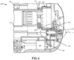
FIG. 4 illustrates a cross-section view of a hoist, in accordance with various embodiments; and -
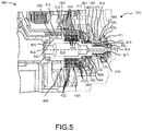
FIG. 5 illustrates a detail cross-section view of an auxiliary brake assembly from the hoist ofFIG. 4 , in accordance with various embodiments. - This detailed description of exemplary embodiments references the accompanying drawings, which show exemplary embodiments by way of illustration. While these exemplary embodiments are described in sufficient detail to enable those skilled in the art to practice the disclosure, it should be understood that other embodiments may be realized and that logical changes and adaptations in design and construction may be made in accordance with this disclosure and the teachings herein described without departing from the scope of the invention as defined by the claims. Thus, this detailed description is presented for purposes of illustration only and not of limitation.
- The scope of the disclosure is defined by the appended claims and their legal equivalents rather than by merely the examples described. For example, the steps recited in any of the method or process descriptions may be executed in any order and are not necessarily limited to the order presented. Furthermore, any reference to singular includes plural embodiments, and any reference to more than one component or step may include a singular embodiment or step. Also, any reference to tacked, attached, fixed, coupled, connected or the like may include permanent, removable, temporary, partial, full and/or any other possible attachment option. Additionally, any reference to without contact (or similar phrases) may also include reduced contact or minimal contact. Cross hatching and surface lines may be used throughout the figures to denote different parts but not necessarily to denote the same or different materials.
- An auxiliary brake assembly for a hoist is disclosed herein. The auxiliary brake assembly may be configured to prevent a cable drum of a hoist from spinning freely. In accordance with various embodiments, the auxiliary brake assembly may include a pinion, a friction disc pack, a pressure plate, a gear nut, a screw, and a bearing. An auxiliary brake assembly may allow for a safer hoist, as compared to conventional hoist designs, which tend to employ a main brake assembly without an additional auxiliary brake assembly.
- Referring now to
FIG. 1 , anaircraft 10, such as a helicopter, is illustrated, in accordance with various embodiments.Aircraft 10 may be used for search and rescue missions. Ahoist 12 is attached to a support ofaircraft 10.Hoist 12 may be used to extend and/or retract (e.g., lower and/or raise, respectively) a cable 14 (e.g., a wire-rope) connected to aload 16 via ahook 18 and/or the like. In various embodiments, theload 16 placed on thehoist 12 can exceed a load rating for thehoist 12, thereby putting theaircraft 10, thehoist 12, and/or theload 16, etc. at risk. - Referring now also to
FIG. 2 , a schematic block diagram of a brake system 1 for ahoist 12 is illustrated, in accordance with various embodiments. A motor 2 is operatively connected to a brake 4 through gearing 3, which is operatively connected to theclutch 5, which is operatively connected to a drum 7. The motor 2 is activated to provide drive to the drum 7 through the gearing 3, the brake 4, theclutch 5, to wind up (or release) awinch cable 7a to lift (or drop) a payload 8. The drum 7 and thecable 7a together form awinch 9. The main brake 4 is grounded to a structure to stopcable 7a winding without disengaging the motor 2, whereas theclutch 5 acts as a moderating the drive, allowing the drum 7 to be disconnected from the motor 2 should the drum 7 become overloaded. An auxiliary brake 6 is grounded to a structure to stopcable 7a from winding in the event the main brake 4 is unable to stop the unwinding ofcable 7a. - Referring now to
FIG. 3 , a perspective view of a rescue hoist, in accordance with various embodiments, is depicted. The rescue hoist 210 includes acable drum 212, having a firstradial flange 228, a secondradial flange 230 and abarrel 232 extending axially between the firstradial flange 228 and the secondradial flange 230. In various embodiments, thecable drum 212 is disposed radially outward of atorque tube 240, within which a motor and a drive mechanism may be at least partially housed. In various embodiments, both thetorque tube 240 and thecable drum 212 are configured to rotate about a longitudinal axis A. Thecable drum 212 is also configured to translate back and forth with respect to the longitudinal axis A. - The rescue hoist 210 includes a
speed reduction mechanism 242, which may, in various embodiments, include or be coupled to aplanetary gear 250 configured to be driven by a ring gear disposed radially outward of thetorque tube 240 and driven by a motor and a drive train. Thespeed reduction mechanism 242 may also be coupled to alevel wind mechanism 220. In various embodiments, thelevel wind mechanism 220 includes afirst screw 260 and asecond screw 262, both screws extending axially along a radiallyouter surface 241 of thetorque tube 240. - Referring now to
FIG. 4 , a cross-sectional view of a rescue hoist along longitudinal axis A, in accordance with various embodiments, is depicted. Hoist 300 includestorque tube 310 andcable drum 320. In various embodiments, a gear box outputs torque totorque tube 310 and drives thecable drum 320 and rotatescable drum 320 about its longitudinal axis.Torque tube 310 is coupled tocable drum 320 by any method known in the art. For example,torque tube 310 may be coupled tocable drum 320 at afirst end 312 oftorque tube 310 by aball bearing assembly 350. Theball bearing assembly 350 may reduce rotational friction between thetorque tube 310 and thecable drum 320. - In various embodiments, hoist 300 further comprises an
auxiliary brake assembly 330.Auxiliary brake assembly 330 is configured to stopcable drum 320 in the event thatcable drum 320 is spinning freely. In various embodiments,auxiliary brake assembly 330 is coupled to arotor gear 340. In various embodiments,rotor gear 340 is a spur gear having teeth projecting parallel to an axis of therotor gear 340. Theauxiliary brake assembly 330 is configured to lock therotor gear 340 which locks thetorque tube 310, which in turn locks thecable drum 320 in the event the cable drum begins to spin freely. - In various embodiments, hoist 300 further comprises an
electric motor 360.Electric motor 360 may be in electrical communication with a brake controller. The Brake controller may detect a free spinning event by the cable drum and send an electrical signal to electric motor. Upon receiving a signal from a brake controller,electric motor 360 drives afirst stage gear 362 disposed aft of theelectric motor 360.First stage gear 362 may be coupled to asecond stage gear 364.Second stage gear 364 may be coupled toauxiliary brake assembly 330.First stage gear 362 may engagesecond stage gear 364 and causeauxiliary brake assembly 330 to translate forward, lock therotor gear 340, and stop thecable drum 320 from spinning. In various embodiments,first stage gear 362 andsecond stage gear 364 are cluster gears. - Referring now to
FIG. 5 , a detail perspective view of a cross-section ofauxiliary brake assembly 330 of hoist 300, in accordance with various embodiments, is depicted. In various embodiments, theauxiliary brake assembly 330 comprises apinion 410, afastener 420,spring 430, apressure plate 440, aclutch assembly 450, and ahub 460. Thepinion 410 is disposed radially adjacent from therotor gear 340. In various embodiments, thepinion 410 may be disposed radially outward fromrotor gear 340 or radially inward fromrotor gear 340. The pinion comprises afirst end 411 and asecond end 419. Thefirst end 411 may comprise a shoulder and be configured to receive abearing 405. Bearing 405 may be configured to reduce rotational friction ofpinion 410, support radial loads, and/or support axial loads. Bearing 405 may comprise a ball bearing, or the like. - The
pinion 410 further comprises amesh gear 412 configured to engage arespective mesh gear 342 ofrotor gear 340 during normal operation of hoist 300. A first radiallyouter surface 413 ofpinion 410 may be disposed axially adjacent to meshgear 412. Thepinion 410 may further comprise a second radiallyouter surface 415 disposed axially adjacent to the first radiallyouter surface 413 and a third radiallyouter surface 416 disposed axially adjacent to second radiallyouter surface 415. Thepinion 410 may rotate about a pinion axis B during normal operation asrotor gear 340 rotates about longitudinal axis A (fromFIG. 3 ) of the hoist 300 via engagement betweenmesh gear 412 andrespective mesh gear 342. - In various embodiments,
fastener 420 may comprise a male fastener 470 and afemale fastener 480. Male fastener 470 may be disposed axially adjacent to, and engage,female fastener 480. Male fastener 470 comprises afirst end 471 and asecond end 479 disposed opposite thefirst end 471. Male fastener 470 may comprise a threadedportion 475 disposed at thesecond end 479 of male fastener 470. Male fastener 470 may further comprise an aperture extending axially fromfirst end 471 tosecond end 479. Male fastener 470 may comprise a radiallyinner surface 477 opposite threadedportion 475 and defined by the aperture. The radiallyinner surface 477 may be configured to engage abearing 478. In various embodiments, bearing 478 may be a needle bearing, or any other bearing commonly known in the art. In various embodiments, male fastener 470 may comprise agroove 472 disposed atfirst end 471. Thegroove 472 may be configured to receive abearing 473. Bearing 473 may be disposed withingroove 472 and coupled topinion 410 proximate thesecond end 419 ofpinion 410. Bearing 473 may comprise a thrust bearing, or any other bearing known in the art. Bearing 473 may be configured to support high axial loads and/or the like. - In various embodiments,
female fastener 480 comprises a gear nut. Female fastener comprises a first end 481 and asecond end 489 opposite the first end 481. First end 481 may comprise a threadedportion 482 disposed on a radially inner surface of first end 481. The threadedportion 482 may be configured to received threadedportion 475 of male fastener 470.Second end 489 may comprise agroove 488 disposed on a radially inner surface of thesecond end 489 and a radially outer surface disposed opposite the radially inner surface. Thefemale fastener 480 may further comprise aflange 485 extending radially outward from the radially outer surface ofsecond end 489. Thegroove 488 may be configured to receive abearing 487. Bearing 487 may be disposed betweengroove 488 and second radiallyouter surface 415 ofpinion 410. In various embodiments, bearing 487 may be a roller bearing, or the like. In various embodiments, bearing 487 may be configured to provide radial load support toauxiliary brake assembly 330. - In various embodiments,
spring 430 is disposed betweenflange 485 offemale fastener 480 andpressure plate 440. In various embodiments,spring 430 comprises a cupped spring washer, a coil spring, a nested wave spring, or any other spring known in the art. In various embodiments,pressure plate 440 is disposed betweenspring 430 andclutch assembly 450. During a hoist free spinning event,flange 485 offemale fastener 480 translates towardspressure plate 440 and compressesspring 430.Spring 430 may then apply a force toclutch assembly 450 and compressclutch assembly 450. A "hoist free spinning event," as described herein, refers to an event where a cable drum of a hoist 300 is spinning freely, such as when a cable starts to real out if the system is unable to oppose the mechanical force exerted on the cable. This may occur if one of the components becomes non-operational. - In various embodiments,
clutch assembly 450 comprises a first plurality offriction discs 452, a second plurality offriction discs 454, and a plurality ofreaction plates 456. In various embodiments,clutch assembly 450 is lubricated with oil (e.g., a wet assembly).Clutch assembly 450 is disposed axially betweenmesh gear 412 ofpinion 410 andpressure plate 440.Clutch assembly 450 is disposed radially between first radiallyouter surface 413 ofpinion 410 andhub 460. The first plurality offriction discs 452 may be coupled to a first radiallyouter surface 413 ofpinion 410. The first plurality offriction discs 452 extend radially outward from first radiallyouter surface 413 ofpinion 410. In various embodiments, each friction disc in the second plurality offriction discs 452 are coupled to, and extend radially inward from, thehub 460 towards first radiallyouter surface 413 ofpinion 410. In various embodiments, thehub 460 is grounded tostructure 490. The plurality ofreaction plates 456 may be interleaved between the first plurality offriction discs 452 and/or the second plurality offriction discs 454. In various embodiments, there may be an equal number of first plurality offriction discs 452 and the second plurality offriction discs 454. In various embodiments, there may be a different number of first plurality offriction discs 452 and second plurality offriction discs 454. When in use, the first plurality offriction discs 452 and the second plurality offriction discs 454 are clamped and create a torque between thepinion 410 and thehub 460, locking thepinion 410, and in turn, locking therotor gear 340. - In various embodiments, the
auxiliary brake assembly 330 further comprises anut 495 disposed at thesecond end 419 ofpinion 410. Thenut 495 mechanically couples theauxiliary brake assembly 330 together. In various embodiments, thenut 495 is configured to spin with thepinion 410 during normal operation. In various embodiments, with reference now toFIGS. 4 and5 ,flange 485 offemale fastener 480 may be coupled tosecond stage gear 364 by any method known in the art. - Benefits, other advantages, and solutions to problems have been described herein with regard to specific embodiments. Furthermore, the connecting lines shown in the various figures contained herein are intended to represent exemplary functional relationships and/or physical couplings between the various elements. It should be noted that many alternative or additional functional relationships or physical connections may be present in a practical system. However, the benefits, advantages, solutions to problems, and any elements that may cause any benefit, advantage, or solution to occur or become more pronounced are not to be construed as critical, required, or essential features or elements of the inventions. The scope of the inventions is accordingly to be limited by nothing other than the appended claims, in which reference to an element in the singular is not intended to mean "one and only one" unless explicitly so stated, but rather "one or more." Moreover, where a phrase similar to "at least one of A, B, or C" is used in the claims, it is intended that the phrase be interpreted to mean that A alone may be present in an embodiment, B alone may be present in an embodiment, C alone may be present in an embodiment, or that any combination of the elements A, B and C may be present in a single embodiment; for example, A and B, A and C, B and C, or A and B and C.
- Systems, methods and apparatus are provided herein. In the detailed description herein, references to "one embodiment," "an embodiment," "various embodiments," etc., indicate that the embodiment described may include a particular feature, structure, or characteristic, but every embodiment may not necessarily include the particular feature, structure, or characteristic. Moreover, such phrases are not necessarily referring to the same embodiment. Further, when a particular feature, structure, or characteristic is described in connection with an embodiment, it is submitted that it may be within the knowledge of one skilled in the art to affect such feature, structure, or characteristic in connection with other embodiments whether or not explicitly described. After reading the description, it will be apparent to one skilled in the relevant art(s) how to implement the disclosure in alternative embodiments.
Claims (15)
- An auxiliary brake assembly comprising:a pinion (410) having a first end (411), a second end (419) and a mesh gear (412), the first end opposite the second end, and the mesh gear axially adjacent to the first end;a fastener (420) including a flange (485) extending radially outward from a radially outer surface of the fastener; anda clutch assembly (450) coupled to the pinion and a grounded hub (460), the clutch assembly disposed between the fastener and the mesh gear.
- The auxiliary brake assembly of claim 1, further comprising a spring (430) disposed between the flange and the clutch assembly.
- The auxiliary brake assembly of claim 2, further comprising a pressure plate (440) disposed between the spring and the clutch assembly.
- The auxiliary brake assembly of any preceding claim, wherein the clutch assembly further comprises a first plurality of friction discs (452) coupled to a second pinion radially outer surface, a second plurality of friction discs (454) coupled to the grounded hub, and a plurality of reaction plates (456) interleaved between the second plurality of friction discs.
- The auxiliary brake assembly of any preceding claim, wherein the pinion defines a longitudinal axis, the pinion configured to spin about the longitudinal axis via engagement of the mesh gear of the pinion.
- The auxiliary brake assembly of claim 5, wherein the flange is configured to compress the clutch assembly and lock the pinion.
- The auxiliary brake assembly of claim 3 or any claim dependent thereon, wherein the fastener includes a male fastener (470) and a female fastener (480), the female fastener comprising the flange, the male fastener coupled to the female fastener, and the female fastener disposed between the male fastener and the spring, and optionally further comprising a thrust bearing, wherein the male fastener has a groove disposed on an end of the male fastener, wherein the groove engages the thrust bearing.
- A hoist, comprising:a torque tube (310);a cable drum (212) coupled to the torque tube;a rotor gear (340) coupled to a first end of the torque tube, the rotor gear comprising a first mesh gear;an auxiliary brake assembly (330), comprising:a pinion having a second mesh gear engage the first mesh gear of the rotor gear; anda clutch assembly coupled to the pinion, the clutch assembly configured to lock the pinion when the cable drum is spinning freely.
- The hoist of claim 8, further comprising a main brake (4).
- The hoist of claim 8 or 9, further comprising an electric motor (360) configured to detect when the cable drum is spinning freely and activate the auxiliary brake assembly, and optionally further comprising a first stage gear (362) coupled to the electric motor.
- The hoist of claim 10, further comprising a second stage gear (364) coupled to the first stage gear.
- The hoist of claim 11, wherein the auxiliary brake assembly further comprises a fastener (420) disposed axially adjacent to the clutch assembly, the fastener comprising a flange (485) extending radially outward from a radially outer surface of the fastener, wherein the flange engages the second stage gear, and optionally, wherein the fastener comprises a male fastener (470) and a female fastener (480), the female fastener disposed between the male fastener and the clutch assembly, the female fastener comprising the flange and/or wherein the flange of the fastener is configured to compress the clutch assembly and lock the first mesh gear and the second mesh gear when the cable drum is spinning freely.
- The hoist of any of claims 8 to 12, wherein the clutch assembly comprises a first plurality of friction discs (452) coupled to a radially outer surface of the pinion, the first plurality of friction discs configured to lock the pinion.
- A method of braking for a free spinning cable drum of a hoist, the method comprising:detecting a cable drum is spinning freely;activating an electric motor coupled to an auxiliary brake assembly, the auxiliary brake assembly comprising a pinion engaging a rotor gear, and a clutch assembly coupled to the pinion, the pinion spinning freely;clamping the clutch assembly; andlocking the pinion.
- The method of claim 14, further comprising: locking the rotor gear and/or further comprising: locking the cable drum.
Priority Applications (2)
| Application Number | Priority Date | Filing Date | Title |
|---|---|---|---|
| EP21203518.2A EP3960690A1 (en) | 2019-08-05 | 2019-12-10 | Auxiliary brake assembly |
| EP23182017.6A EP4242163A3 (en) | 2019-08-05 | 2019-12-10 | Hoist with an auxiliary brake assembly |
Applications Claiming Priority (1)
| Application Number | Priority Date | Filing Date | Title |
|---|---|---|---|
| US16/532,358 US10947094B2 (en) | 2019-08-05 | 2019-08-05 | Auxiliary brake assembly |
Related Child Applications (4)
| Application Number | Title | Priority Date | Filing Date |
|---|---|---|---|
| EP21203518.2A Division-Into EP3960690A1 (en) | 2019-08-05 | 2019-12-10 | Auxiliary brake assembly |
| EP21203518.2A Division EP3960690A1 (en) | 2019-08-05 | 2019-12-10 | Auxiliary brake assembly |
| EP23182017.6A Division-Into EP4242163A3 (en) | 2019-08-05 | 2019-12-10 | Hoist with an auxiliary brake assembly |
| EP23182017.6A Division EP4242163A3 (en) | 2019-08-05 | 2019-12-10 | Hoist with an auxiliary brake assembly |
Publications (2)
| Publication Number | Publication Date |
|---|---|
| EP3772482A1 true EP3772482A1 (en) | 2021-02-10 |
| EP3772482B1 EP3772482B1 (en) | 2023-08-02 |
Family
ID=68848126
Family Applications (3)
| Application Number | Title | Priority Date | Filing Date |
|---|---|---|---|
| EP19214966.4A Active EP3772482B1 (en) | 2019-08-05 | 2019-12-10 | Hoist with an auxiliary brake assembly |
| EP21203518.2A Pending EP3960690A1 (en) | 2019-08-05 | 2019-12-10 | Auxiliary brake assembly |
| EP23182017.6A Pending EP4242163A3 (en) | 2019-08-05 | 2019-12-10 | Hoist with an auxiliary brake assembly |
Family Applications After (2)
| Application Number | Title | Priority Date | Filing Date |
|---|---|---|---|
| EP21203518.2A Pending EP3960690A1 (en) | 2019-08-05 | 2019-12-10 | Auxiliary brake assembly |
| EP23182017.6A Pending EP4242163A3 (en) | 2019-08-05 | 2019-12-10 | Hoist with an auxiliary brake assembly |
Country Status (5)
| Country | Link |
|---|---|
| US (1) | US10947094B2 (en) |
| EP (3) | EP3772482B1 (en) |
| JP (2) | JP7362463B2 (en) |
| CN (1) | CN112320653B (en) |
| CA (1) | CA3063877A1 (en) |
Cited By (1)
| Publication number | Priority date | Publication date | Assignee | Title |
|---|---|---|---|---|
| EP4289779A1 (en) * | 2022-06-07 | 2023-12-13 | Goodrich Actuation Systems Limited | Method for testing the operation of a next generation rescue hoist |
Families Citing this family (9)
| Publication number | Priority date | Publication date | Assignee | Title |
|---|---|---|---|---|
| DE202017105348U1 (en) * | 2017-09-05 | 2018-12-07 | Liebherr-Components Biberach Gmbh | The freefall winch |
| JP7613731B2 (en) | 2021-03-24 | 2025-01-15 | 株式会社ミヤマエ | Electric hoisting device |
| JP7613732B2 (en) | 2021-03-24 | 2025-01-15 | 株式会社ミヤマエ | Backlash prevention structure for electric winding device |
| KR102513545B1 (en) * | 2022-09-09 | 2023-03-23 | 주식회사 제이피케이이노 | Winch reduction gear brake system using bearings |
| KR102513537B1 (en) * | 2022-09-09 | 2023-03-23 | 주식회사 제이피케이이노 | Winch reducer braking system using shaft |
| US12459793B2 (en) | 2022-11-14 | 2025-11-04 | Hornet Acquisitionco, Llc | Method to detect homing loads in rescue hoist and winch assemblies |
| US12466704B2 (en) | 2022-11-14 | 2025-11-11 | Hornet Acquisitionco, Llc | Homing load detecting device for rescue hoist and winch assemblies |
| FR3143583B1 (en) * | 2022-12-16 | 2025-10-31 | Reel | METHOD FOR PROTECTING A LIFTING DEVICE AGAINST OVERLOAD AND DEVICE IMPLEMENTING THIS METHOD |
| CN121909119A (en) | 2023-09-28 | 2026-04-21 | 富士胶片株式会社 | Pretreatment liquid for printing, printing ink set, and printing method |
Citations (5)
| Publication number | Priority date | Publication date | Assignee | Title |
|---|---|---|---|---|
| US3572482A (en) * | 1969-01-03 | 1971-03-30 | Us Army | Automatic clutch and brake for hoists |
| US4227680A (en) * | 1979-02-28 | 1980-10-14 | B. C. Gearworks Ltd. | Hydraulic winch |
| US20030151037A1 (en) * | 2002-02-12 | 2003-08-14 | O'fallon Eugene P. | Winch having internal clutch mechanism |
| EP2581253A1 (en) * | 2011-10-14 | 2013-04-17 | Sumitomo Heavy Industries, Ltd. | Wheel driving speed reducer |
| EP3144171A1 (en) * | 2015-09-18 | 2017-03-22 | Hitachi Construction Machinery Co., Ltd. | Traveling axle device |
Family Cites Families (46)
| Publication number | Priority date | Publication date | Assignee | Title |
|---|---|---|---|---|
| US2017352A (en) * | 1933-09-08 | 1935-10-15 | Quick Alfred Arthur | Winch and like hoisting apparatus |
| US2192842A (en) * | 1937-09-03 | 1940-03-05 | Schat | Winch |
| US2448674A (en) * | 1945-04-23 | 1948-09-07 | Charles H Grant | Hoist |
| US2652230A (en) * | 1949-02-16 | 1953-09-15 | Lake Shore Engineering Company | Winch |
| US3697049A (en) * | 1971-04-22 | 1972-10-10 | David B Wallace | Winch drum drive and control |
| JPS5136139Y2 (en) * | 1971-06-29 | 1976-09-04 | ||
| US3764111A (en) * | 1971-10-26 | 1973-10-09 | Bucyrus Erie Co | Free fall circuit for hydraulic winch |
| US3912229A (en) * | 1972-12-13 | 1975-10-14 | Formac Int Inc | Cable hauling system with hydraulic differential |
| US3853303A (en) * | 1973-06-08 | 1974-12-10 | Caterpillar Tractor Co | Winch brake assembly |
| US4022432A (en) * | 1975-07-07 | 1977-05-10 | Kabushiki Kaisha Komatsu Seisakusho | Power transmission in double-drum winch |
| US4004780A (en) * | 1975-09-23 | 1977-01-25 | Warn Industries, Inc. | Winch |
| US4093034A (en) * | 1975-12-15 | 1978-06-06 | Caterpillar Tractor Co. | Vehicle supported winch |
| SE414393B (en) * | 1976-01-29 | 1980-07-28 | Naviga Ets | DEVICE FOR SLIDING FREE WITH A LINE |
| GB1529331A (en) * | 1976-03-02 | 1978-10-18 | Clarke Chapman Ltd | Winding mechanism |
| US4118013A (en) * | 1977-03-14 | 1978-10-03 | Paccar Of Canada, Ltd. | Self-energizing winch brake and drive |
| JPS53153946U (en) * | 1977-05-10 | 1978-12-04 | ||
| US4312497A (en) * | 1979-10-12 | 1982-01-26 | Morris Whaley, Inc. | Hydraulic winches |
| US4358088A (en) * | 1980-10-14 | 1982-11-09 | Paccar Of Canada Ltd. | Winch drive and braking mechanism |
| US4426064A (en) * | 1981-03-25 | 1984-01-17 | Superwinch, Inc. | Winch drive mechanism |
| DE3630458A1 (en) * | 1986-04-11 | 1988-03-17 | Haacon Hebetech Gmbh | ROPE WINCH, IN PARTICULAR FOR OPERATION BY MEANS OF A HAND CRANK |
| US4746100A (en) | 1986-12-24 | 1988-05-24 | Caterpillar Inc. | Winch drag brake apparatus |
| US4884783A (en) * | 1988-02-12 | 1989-12-05 | Thorn, Inc. | Hoist with oil cooled brake |
| US5513723A (en) | 1994-07-01 | 1996-05-07 | Harnischfeger Corporation | Double-masted crane with improved brake arrangement |
| JP3647122B2 (en) * | 1996-02-15 | 2005-05-11 | 石川島建機株式会社 | winch |
| KR100492920B1 (en) * | 1996-11-19 | 2005-06-02 | 캄주크, 알렉산더 콘스탄티노비치 | Hoist Driven by the Transfer Gearbox a Vehicle |
| JP3508662B2 (en) * | 1998-12-25 | 2004-03-22 | コベルコ建機株式会社 | Hydraulic drive winch control method and device |
| JP2003074603A (en) | 2001-09-04 | 2003-03-12 | Hitachi Constr Mach Co Ltd | Multiplate brake, multiplate clutch, and crane hoisting gear having the brake and clutch |
| GB0212354D0 (en) * | 2002-05-29 | 2002-07-10 | Lucas Western Inc | Power drive unit for cargo handling systems |
| US7270312B1 (en) * | 2006-09-14 | 2007-09-18 | Growth Innovation, Llc | Multifunctional winch drum drive system |
| US7891641B1 (en) * | 2006-10-03 | 2011-02-22 | Ramsey Winch Company | Manual disengaging and self-engaging clutch |
| US7922153B2 (en) * | 2008-09-16 | 2011-04-12 | Runva Mechanical & Electrical Co, LLC | Variable speed winch |
| CN101508405B (en) * | 2009-03-13 | 2011-04-06 | 宁波中意液压马达有限公司 | Hydraulic winch with hand clutch |
| US8328165B2 (en) * | 2009-03-17 | 2012-12-11 | J.R. Clancy, Inc. | Hoist with overspeed protection |
| US9908757B2 (en) * | 2010-03-08 | 2018-03-06 | Wizard Products, Llc | Gas powered self contained portable winch |
| CN102249164B (en) * | 2011-07-22 | 2012-10-10 | 常熟市电力线路起重机有限公司 | Mechanical winching machine |
| US9017219B2 (en) * | 2012-05-03 | 2015-04-28 | Goodrich Corporation | Systems and methods for aircraft braking and taxiing |
| US10766749B2 (en) * | 2014-09-08 | 2020-09-08 | Warn Industries, Inc. | Portable winch |
| US10066683B2 (en) * | 2015-04-10 | 2018-09-04 | Goodrich Corporation | Clutch for a winch |
| US9988249B2 (en) * | 2015-05-19 | 2018-06-05 | Goodrich Corporation | Clutch for a winch or hoist |
| CN104925688B (en) * | 2015-07-06 | 2017-08-22 | 宁波中皇机电有限公司 | A kind of capstan winch of the electronic arrangement of clutch of band |
| US9815551B2 (en) * | 2015-07-20 | 2017-11-14 | Goodrich Corporation | Systems and methods for aircraft braking and taxiing |
| US20170253466A1 (en) | 2016-03-04 | 2017-09-07 | Moventas Gears Oy | Hoist tool for handling a shrink element of a gear system |
| CN206407852U (en) | 2017-01-17 | 2017-08-15 | 叶振良 | A kind of electric block with double brake and antioverloading function |
| US10189686B2 (en) * | 2017-01-19 | 2019-01-29 | Comeup Industries Inc. | Pneumatic and manual clutch of power winch |
| US10569993B2 (en) | 2017-03-29 | 2020-02-25 | Otis Elevator Company | Safety brake actuation mechanism for a hoisted structure |
| DE102017120490A1 (en) * | 2017-09-06 | 2019-03-07 | Liebherr-Components Biberach Gmbh | The freefall winch |
-
2019
- 2019-08-05 US US16/532,358 patent/US10947094B2/en active Active
- 2019-12-04 CA CA3063877A patent/CA3063877A1/en active Pending
- 2019-12-10 EP EP19214966.4A patent/EP3772482B1/en active Active
- 2019-12-10 EP EP21203518.2A patent/EP3960690A1/en active Pending
- 2019-12-10 EP EP23182017.6A patent/EP4242163A3/en active Pending
- 2019-12-12 JP JP2019224120A patent/JP7362463B2/en active Active
- 2019-12-13 CN CN201911284247.XA patent/CN112320653B/en active Active
-
2023
- 2023-10-04 JP JP2023172433A patent/JP7628593B2/en active Active
Patent Citations (5)
| Publication number | Priority date | Publication date | Assignee | Title |
|---|---|---|---|---|
| US3572482A (en) * | 1969-01-03 | 1971-03-30 | Us Army | Automatic clutch and brake for hoists |
| US4227680A (en) * | 1979-02-28 | 1980-10-14 | B. C. Gearworks Ltd. | Hydraulic winch |
| US20030151037A1 (en) * | 2002-02-12 | 2003-08-14 | O'fallon Eugene P. | Winch having internal clutch mechanism |
| EP2581253A1 (en) * | 2011-10-14 | 2013-04-17 | Sumitomo Heavy Industries, Ltd. | Wheel driving speed reducer |
| EP3144171A1 (en) * | 2015-09-18 | 2017-03-22 | Hitachi Construction Machinery Co., Ltd. | Traveling axle device |
Cited By (2)
| Publication number | Priority date | Publication date | Assignee | Title |
|---|---|---|---|---|
| EP4289779A1 (en) * | 2022-06-07 | 2023-12-13 | Goodrich Actuation Systems Limited | Method for testing the operation of a next generation rescue hoist |
| US12460996B2 (en) | 2022-06-07 | 2025-11-04 | Goodrich Actuation Systems Limited | Method for testing the operation of a next generation rescue hoist |
Also Published As
| Publication number | Publication date |
|---|---|
| EP3772482B1 (en) | 2023-08-02 |
| JP2021024735A (en) | 2021-02-22 |
| CN112320653A (en) | 2021-02-05 |
| EP4242163A3 (en) | 2023-09-20 |
| EP3960690A1 (en) | 2022-03-02 |
| CN112320653B (en) | 2023-06-16 |
| EP4242163A2 (en) | 2023-09-13 |
| US20210039928A1 (en) | 2021-02-11 |
| CA3063877A1 (en) | 2021-02-05 |
| JP7628593B2 (en) | 2025-02-10 |
| JP2023168522A (en) | 2023-11-24 |
| US10947094B2 (en) | 2021-03-16 |
| BR102020000359A2 (en) | 2021-02-17 |
| JP7362463B2 (en) | 2023-10-17 |
Similar Documents
| Publication | Publication Date | Title |
|---|---|---|
| US10947094B2 (en) | Auxiliary brake assembly | |
| US20070227835A1 (en) | Roller disk brake for a winch | |
| EP3715657B1 (en) | Overload clutch assembly for hoist | |
| EP3715660A1 (en) | Self adjusting automatic load brake | |
| US9994432B2 (en) | Hoist cable drum with an integral ball spline and internal gear ring | |
| EP3772803B1 (en) | Rescue hoist cooling system | |
| EP3715312B1 (en) | Automatic load brake having wear-induced locking mechanism | |
| EP4428384A1 (en) | Capstan with integrated torque limiting overload clutch | |
| KR100492920B1 (en) | Hoist Driven by the Transfer Gearbox a Vehicle | |
| US10351397B2 (en) | Chain hoist | |
| US20020194944A1 (en) | Remote brake release with clutch | |
| BR122025019384A2 (en) | WINCH AND BRAKING METHOD FOR A FREE-ROTATING CABLE DRUM OF A WINCH | |
| BR102020000359B1 (en) | AUXILIARY BRAKE ASSEMBLY | |
| BR102020000424B1 (en) | Clutch assembly for a winch, and winch. | |
| RU2783014C1 (en) | Device for tensioning a rope coming from a remotely positioned drum | |
| RU2226172C2 (en) | Lift car travel motion device | |
| CN113148880A (en) | Tower machine wire rope air bleeder | |
| CZ176999A3 (en) | Lifting device driven by vehicle gearbox |
Legal Events
| Date | Code | Title | Description |
|---|---|---|---|
| PUAI | Public reference made under article 153(3) epc to a published international application that has entered the european phase |
Free format text: ORIGINAL CODE: 0009012 |
|
| STAA | Information on the status of an ep patent application or granted ep patent |
Free format text: STATUS: THE APPLICATION HAS BEEN PUBLISHED |
|
| AK | Designated contracting states |
Kind code of ref document: A1 Designated state(s): AL AT BE BG CH CY CZ DE DK EE ES FI FR GB GR HR HU IE IS IT LI LT LU LV MC MK MT NL NO PL PT RO RS SE SI SK SM TR |
|
| AX | Request for extension of the european patent |
Extension state: BA ME |
|
| STAA | Information on the status of an ep patent application or granted ep patent |
Free format text: STATUS: REQUEST FOR EXAMINATION WAS MADE |
|
| 17P | Request for examination filed |
Effective date: 20210810 |
|
| RBV | Designated contracting states (corrected) |
Designated state(s): AL AT BE BG CH CY CZ DE DK EE ES FI FR GB GR HR HU IE IS IT LI LT LU LV MC MK MT NL NO PL PT RO RS SE SI SK SM TR |
|
| GRAP | Despatch of communication of intention to grant a patent |
Free format text: ORIGINAL CODE: EPIDOSNIGR1 |
|
| STAA | Information on the status of an ep patent application or granted ep patent |
Free format text: STATUS: GRANT OF PATENT IS INTENDED |
|
| INTG | Intention to grant announced |
Effective date: 20230217 |
|
| GRAS | Grant fee paid |
Free format text: ORIGINAL CODE: EPIDOSNIGR3 |
|
| GRAA | (expected) grant |
Free format text: ORIGINAL CODE: 0009210 |
|
| STAA | Information on the status of an ep patent application or granted ep patent |
Free format text: STATUS: THE PATENT HAS BEEN GRANTED |
|
| AK | Designated contracting states |
Kind code of ref document: B1 Designated state(s): AL AT BE BG CH CY CZ DE DK EE ES FI FR GB GR HR HU IE IS IT LI LT LU LV MC MK MT NL NO PL PT RO RS SE SI SK SM TR |
|
| REG | Reference to a national code |
Ref country code: GB Ref legal event code: FG4D |
|
| REG | Reference to a national code |
Ref country code: CH Ref legal event code: EP |
|
| REG | Reference to a national code |
Ref country code: DE Ref legal event code: R096 Ref document number: 602019033948 Country of ref document: DE |
|
| REG | Reference to a national code |
Ref country code: IE Ref legal event code: FG4D |
|
| P01 | Opt-out of the competence of the unified patent court (upc) registered |
Effective date: 20230922 |
|
| REG | Reference to a national code |
Ref country code: LT Ref legal event code: MG9D |
|
| REG | Reference to a national code |
Ref country code: NL Ref legal event code: MP Effective date: 20230802 |
|
| REG | Reference to a national code |
Ref country code: AT Ref legal event code: MK05 Ref document number: 1594550 Country of ref document: AT Kind code of ref document: T Effective date: 20230802 |
|
| PG25 | Lapsed in a contracting state [announced via postgrant information from national office to epo] |
Ref country code: GR Free format text: LAPSE BECAUSE OF FAILURE TO SUBMIT A TRANSLATION OF THE DESCRIPTION OR TO PAY THE FEE WITHIN THE PRESCRIBED TIME-LIMIT Effective date: 20231103 |
|
| PG25 | Lapsed in a contracting state [announced via postgrant information from national office to epo] |
Ref country code: IS Free format text: LAPSE BECAUSE OF FAILURE TO SUBMIT A TRANSLATION OF THE DESCRIPTION OR TO PAY THE FEE WITHIN THE PRESCRIBED TIME-LIMIT Effective date: 20231202 |
|
| PG25 | Lapsed in a contracting state [announced via postgrant information from national office to epo] |
Ref country code: SE Free format text: LAPSE BECAUSE OF FAILURE TO SUBMIT A TRANSLATION OF THE DESCRIPTION OR TO PAY THE FEE WITHIN THE PRESCRIBED TIME-LIMIT Effective date: 20230802 Ref country code: RS Free format text: LAPSE BECAUSE OF FAILURE TO SUBMIT A TRANSLATION OF THE DESCRIPTION OR TO PAY THE FEE WITHIN THE PRESCRIBED TIME-LIMIT Effective date: 20230802 Ref country code: PT Free format text: LAPSE BECAUSE OF FAILURE TO SUBMIT A TRANSLATION OF THE DESCRIPTION OR TO PAY THE FEE WITHIN THE PRESCRIBED TIME-LIMIT Effective date: 20231204 Ref country code: NO Free format text: LAPSE BECAUSE OF FAILURE TO SUBMIT A TRANSLATION OF THE DESCRIPTION OR TO PAY THE FEE WITHIN THE PRESCRIBED TIME-LIMIT Effective date: 20231102 Ref country code: NL Free format text: LAPSE BECAUSE OF FAILURE TO SUBMIT A TRANSLATION OF THE DESCRIPTION OR TO PAY THE FEE WITHIN THE PRESCRIBED TIME-LIMIT Effective date: 20230802 Ref country code: LV Free format text: LAPSE BECAUSE OF FAILURE TO SUBMIT A TRANSLATION OF THE DESCRIPTION OR TO PAY THE FEE WITHIN THE PRESCRIBED TIME-LIMIT Effective date: 20230802 Ref country code: LT Free format text: LAPSE BECAUSE OF FAILURE TO SUBMIT A TRANSLATION OF THE DESCRIPTION OR TO PAY THE FEE WITHIN THE PRESCRIBED TIME-LIMIT Effective date: 20230802 Ref country code: IS Free format text: LAPSE BECAUSE OF FAILURE TO SUBMIT A TRANSLATION OF THE DESCRIPTION OR TO PAY THE FEE WITHIN THE PRESCRIBED TIME-LIMIT Effective date: 20231202 Ref country code: HR Free format text: LAPSE BECAUSE OF FAILURE TO SUBMIT A TRANSLATION OF THE DESCRIPTION OR TO PAY THE FEE WITHIN THE PRESCRIBED TIME-LIMIT Effective date: 20230802 Ref country code: GR Free format text: LAPSE BECAUSE OF FAILURE TO SUBMIT A TRANSLATION OF THE DESCRIPTION OR TO PAY THE FEE WITHIN THE PRESCRIBED TIME-LIMIT Effective date: 20231103 Ref country code: FI Free format text: LAPSE BECAUSE OF FAILURE TO SUBMIT A TRANSLATION OF THE DESCRIPTION OR TO PAY THE FEE WITHIN THE PRESCRIBED TIME-LIMIT Effective date: 20230802 Ref country code: AT Free format text: LAPSE BECAUSE OF FAILURE TO SUBMIT A TRANSLATION OF THE DESCRIPTION OR TO PAY THE FEE WITHIN THE PRESCRIBED TIME-LIMIT Effective date: 20230802 |
|
| PG25 | Lapsed in a contracting state [announced via postgrant information from national office to epo] |
Ref country code: PL Free format text: LAPSE BECAUSE OF FAILURE TO SUBMIT A TRANSLATION OF THE DESCRIPTION OR TO PAY THE FEE WITHIN THE PRESCRIBED TIME-LIMIT Effective date: 20230802 |
|
| PG25 | Lapsed in a contracting state [announced via postgrant information from national office to epo] |
Ref country code: ES Free format text: LAPSE BECAUSE OF FAILURE TO SUBMIT A TRANSLATION OF THE DESCRIPTION OR TO PAY THE FEE WITHIN THE PRESCRIBED TIME-LIMIT Effective date: 20230802 |
|
| PG25 | Lapsed in a contracting state [announced via postgrant information from national office to epo] |
Ref country code: SM Free format text: LAPSE BECAUSE OF FAILURE TO SUBMIT A TRANSLATION OF THE DESCRIPTION OR TO PAY THE FEE WITHIN THE PRESCRIBED TIME-LIMIT Effective date: 20230802 Ref country code: RO Free format text: LAPSE BECAUSE OF FAILURE TO SUBMIT A TRANSLATION OF THE DESCRIPTION OR TO PAY THE FEE WITHIN THE PRESCRIBED TIME-LIMIT Effective date: 20230802 Ref country code: ES Free format text: LAPSE BECAUSE OF FAILURE TO SUBMIT A TRANSLATION OF THE DESCRIPTION OR TO PAY THE FEE WITHIN THE PRESCRIBED TIME-LIMIT Effective date: 20230802 Ref country code: EE Free format text: LAPSE BECAUSE OF FAILURE TO SUBMIT A TRANSLATION OF THE DESCRIPTION OR TO PAY THE FEE WITHIN THE PRESCRIBED TIME-LIMIT Effective date: 20230802 Ref country code: DK Free format text: LAPSE BECAUSE OF FAILURE TO SUBMIT A TRANSLATION OF THE DESCRIPTION OR TO PAY THE FEE WITHIN THE PRESCRIBED TIME-LIMIT Effective date: 20230802 Ref country code: CZ Free format text: LAPSE BECAUSE OF FAILURE TO SUBMIT A TRANSLATION OF THE DESCRIPTION OR TO PAY THE FEE WITHIN THE PRESCRIBED TIME-LIMIT Effective date: 20230802 Ref country code: SK Free format text: LAPSE BECAUSE OF FAILURE TO SUBMIT A TRANSLATION OF THE DESCRIPTION OR TO PAY THE FEE WITHIN THE PRESCRIBED TIME-LIMIT Effective date: 20230802 |
|
| REG | Reference to a national code |
Ref country code: DE Ref legal event code: R097 Ref document number: 602019033948 Country of ref document: DE |
|
| PG25 | Lapsed in a contracting state [announced via postgrant information from national office to epo] |
Ref country code: IT Free format text: LAPSE BECAUSE OF FAILURE TO SUBMIT A TRANSLATION OF THE DESCRIPTION OR TO PAY THE FEE WITHIN THE PRESCRIBED TIME-LIMIT Effective date: 20230802 |
|
| PLBE | No opposition filed within time limit |
Free format text: ORIGINAL CODE: 0009261 |
|
| STAA | Information on the status of an ep patent application or granted ep patent |
Free format text: STATUS: NO OPPOSITION FILED WITHIN TIME LIMIT |
|
| 26N | No opposition filed |
Effective date: 20240503 |
|
| PG25 | Lapsed in a contracting state [announced via postgrant information from national office to epo] |
Ref country code: SI Free format text: LAPSE BECAUSE OF FAILURE TO SUBMIT A TRANSLATION OF THE DESCRIPTION OR TO PAY THE FEE WITHIN THE PRESCRIBED TIME-LIMIT Effective date: 20230802 |
|
| REG | Reference to a national code |
Ref country code: CH Ref legal event code: PL |
|
| PG25 | Lapsed in a contracting state [announced via postgrant information from national office to epo] |
Ref country code: LU Free format text: LAPSE BECAUSE OF NON-PAYMENT OF DUE FEES Effective date: 20231210 |
|
| PG25 | Lapsed in a contracting state [announced via postgrant information from national office to epo] |
Ref country code: MC Free format text: LAPSE BECAUSE OF FAILURE TO SUBMIT A TRANSLATION OF THE DESCRIPTION OR TO PAY THE FEE WITHIN THE PRESCRIBED TIME-LIMIT Effective date: 20230802 |
|
| REG | Reference to a national code |
Ref country code: BE Ref legal event code: MM Effective date: 20231231 |
|
| PG25 | Lapsed in a contracting state [announced via postgrant information from national office to epo] |
Ref country code: MC Free format text: LAPSE BECAUSE OF FAILURE TO SUBMIT A TRANSLATION OF THE DESCRIPTION OR TO PAY THE FEE WITHIN THE PRESCRIBED TIME-LIMIT Effective date: 20230802 Ref country code: LU Free format text: LAPSE BECAUSE OF NON-PAYMENT OF DUE FEES Effective date: 20231210 |
|
| REG | Reference to a national code |
Ref country code: IE Ref legal event code: MM4A |
|
| PG25 | Lapsed in a contracting state [announced via postgrant information from national office to epo] |
Ref country code: IE Free format text: LAPSE BECAUSE OF NON-PAYMENT OF DUE FEES Effective date: 20231210 |
|
| PG25 | Lapsed in a contracting state [announced via postgrant information from national office to epo] |
Ref country code: BE Free format text: LAPSE BECAUSE OF NON-PAYMENT OF DUE FEES Effective date: 20231231 |
|
| PG25 | Lapsed in a contracting state [announced via postgrant information from national office to epo] |
Ref country code: CH Free format text: LAPSE BECAUSE OF NON-PAYMENT OF DUE FEES Effective date: 20231231 |
|
| PG25 | Lapsed in a contracting state [announced via postgrant information from national office to epo] |
Ref country code: IE Free format text: LAPSE BECAUSE OF NON-PAYMENT OF DUE FEES Effective date: 20231210 Ref country code: CH Free format text: LAPSE BECAUSE OF NON-PAYMENT OF DUE FEES Effective date: 20231231 Ref country code: BE Free format text: LAPSE BECAUSE OF NON-PAYMENT OF DUE FEES Effective date: 20231231 |
|
| PG25 | Lapsed in a contracting state [announced via postgrant information from national office to epo] |
Ref country code: BG Free format text: LAPSE BECAUSE OF FAILURE TO SUBMIT A TRANSLATION OF THE DESCRIPTION OR TO PAY THE FEE WITHIN THE PRESCRIBED TIME-LIMIT Effective date: 20230802 |
|
| PG25 | Lapsed in a contracting state [announced via postgrant information from national office to epo] |
Ref country code: BG Free format text: LAPSE BECAUSE OF FAILURE TO SUBMIT A TRANSLATION OF THE DESCRIPTION OR TO PAY THE FEE WITHIN THE PRESCRIBED TIME-LIMIT Effective date: 20230802 |
|
| REG | Reference to a national code |
Ref country code: DE Ref legal event code: R081 Ref document number: 602019033948 Country of ref document: DE Owner name: HORNET ACQUISITIONCO, LLC, VANCOUVER, US Free format text: FORMER OWNER: GOODRICH CORPORATION, CHARLOTTE, NC, US |
|
| REG | Reference to a national code |
Ref country code: GB Ref legal event code: 732E Free format text: REGISTERED BETWEEN 20250501 AND 20250507 |
|
| PG25 | Lapsed in a contracting state [announced via postgrant information from national office to epo] |
Ref country code: CY Free format text: LAPSE BECAUSE OF FAILURE TO SUBMIT A TRANSLATION OF THE DESCRIPTION OR TO PAY THE FEE WITHIN THE PRESCRIBED TIME-LIMIT; INVALID AB INITIO Effective date: 20191210 |
|
| PG25 | Lapsed in a contracting state [announced via postgrant information from national office to epo] |
Ref country code: HU Free format text: LAPSE BECAUSE OF FAILURE TO SUBMIT A TRANSLATION OF THE DESCRIPTION OR TO PAY THE FEE WITHIN THE PRESCRIBED TIME-LIMIT; INVALID AB INITIO Effective date: 20191210 |
|
| PG25 | Lapsed in a contracting state [announced via postgrant information from national office to epo] |
Ref country code: TR Free format text: LAPSE BECAUSE OF FAILURE TO SUBMIT A TRANSLATION OF THE DESCRIPTION OR TO PAY THE FEE WITHIN THE PRESCRIBED TIME-LIMIT Effective date: 20230802 |
|
| PGFP | Annual fee paid to national office [announced via postgrant information from national office to epo] |
Ref country code: GB Payment date: 20251229 Year of fee payment: 7 |
|
| PGFP | Annual fee paid to national office [announced via postgrant information from national office to epo] |
Ref country code: FR Payment date: 20251226 Year of fee payment: 7 |
|
| PGFP | Annual fee paid to national office [announced via postgrant information from national office to epo] |
Ref country code: DE Payment date: 20251229 Year of fee payment: 7 |