EP3772435A1 - Wire harness protector - Google Patents
Wire harness protector Download PDFInfo
- Publication number
- EP3772435A1 EP3772435A1 EP20189500.0A EP20189500A EP3772435A1 EP 3772435 A1 EP3772435 A1 EP 3772435A1 EP 20189500 A EP20189500 A EP 20189500A EP 3772435 A1 EP3772435 A1 EP 3772435A1
- Authority
- EP
- European Patent Office
- Prior art keywords
- wire harness
- protector
- protector body
- cover
- corrugated
- Prior art date
- Legal status (The legal status is an assumption and is not a legal conclusion. Google has not performed a legal analysis and makes no representation as to the accuracy of the status listed.)
- Granted
Links
Images

Classifications
-
- B—PERFORMING OPERATIONS; TRANSPORTING
- B60—VEHICLES IN GENERAL
- B60R—VEHICLES, VEHICLE FITTINGS, OR VEHICLE PARTS, NOT OTHERWISE PROVIDED FOR
- B60R16/00—Electric or fluid circuits specially adapted for vehicles and not otherwise provided for; Arrangement of elements of electric or fluid circuits specially adapted for vehicles and not otherwise provided for
- B60R16/02—Electric or fluid circuits specially adapted for vehicles and not otherwise provided for; Arrangement of elements of electric or fluid circuits specially adapted for vehicles and not otherwise provided for electric constitutive elements
- B60R16/0207—Wire harnesses
- B60R16/0215—Protecting, fastening and routing means therefor
-
- H—ELECTRICITY
- H02—GENERATION; CONVERSION OR DISTRIBUTION OF ELECTRIC POWER
- H02G—INSTALLATION OF ELECTRIC CABLES OR LINES, OR OF COMBINED OPTICAL AND ELECTRIC CABLES OR LINES
- H02G3/00—Installations of electric cables or lines or protective tubing therefor in or on buildings, equivalent structures or vehicles
- H02G3/30—Installations of cables or lines on walls, floors or ceilings
- H02G3/32—Installations of cables or lines on walls, floors or ceilings using mounting clamps
-
- H—ELECTRICITY
- H02—GENERATION; CONVERSION OR DISTRIBUTION OF ELECTRIC POWER
- H02G—INSTALLATION OF ELECTRIC CABLES OR LINES, OR OF COMBINED OPTICAL AND ELECTRIC CABLES OR LINES
- H02G3/00—Installations of electric cables or lines or protective tubing therefor in or on buildings, equivalent structures or vehicles
- H02G3/02—Details
- H02G3/04—Protective tubing or conduits, e.g. cable ladders or cable troughs
- H02G3/0462—Tubings, i.e. having a closed section
- H02G3/0468—Corrugated
-
- H—ELECTRICITY
- H02—GENERATION; CONVERSION OR DISTRIBUTION OF ELECTRIC POWER
- H02G—INSTALLATION OF ELECTRIC CABLES OR LINES, OR OF COMBINED OPTICAL AND ELECTRIC CABLES OR LINES
- H02G3/00—Installations of electric cables or lines or protective tubing therefor in or on buildings, equivalent structures or vehicles
- H02G3/02—Details
- H02G3/06—Joints for connecting lengths of protective tubing or channels, to each other or to casings, e.g. to distribution boxes; Ensuring electrical continuity in the joint
- H02G3/0616—Joints for connecting tubing to casing
- H02G3/0691—Fixing tubing to casing by auxiliary means co-operating with indentations of the tubing, e.g. with tubing-convolutions
Definitions
- the present invention is related to a wire harness protector that fixes a corrugated tube through which a wire harness is inserted to accommodate the corrugated tube in a packing box.
- Japanese Utility Model Application Publication No. H5-25919 describes a wire harness protector that fixes a corrugated tube through which a wire harness is inserted to accommodate the corrugated tube in a packing box.
- the wire harness protector includes: a protector body that has a substantially U-shaped cross section and accommodates the corrugated tube through which the wire harness formed from electric wires are inserted; and a cover that covers an opening of the protector body. The front end of the protector body and the front end of the cover are arranged at the same position.
- the route of the corrugated tube is regulated by using the wire harness protector in order to secure a vehicle mounting performance of the wire harness.
- the wire harness protector is transported to a factory or the like where the wire harness protector is mounted on a vehicle, the wire harness protector is accommodated in a packing box with the corrugated tube exposed from the front end of the protector body being folded outward and upward along the front end of the protector body.
- the corrugated tube When the wire harness protector is accommodated in the packing box, the corrugated tube is folded in a state of being largely projected outward from the front end of the protector body. Therefore, the size of the packing box for transportation of the wire harness is increased, the amount to be transported is increased, and a large storage space is required. Thus the costs are increased accordingly.
- An object of the present invention is to provide a wire harness protector that is capable of reducing transportation costs and storage costs.
- a wire harness protector in accordance with the present invention includes: a protector body configured to accommodate a corrugated tube extending in a front-rear direction and through which a wire harness is inserted; and a cover configured to cover an opening of the protector body.
- a first front end being one of a front end of the protector body or a front end of the cover is arranged rearward of a second front end being the other of the front ends.
- a portion of the wire harness protector located at the first front end includes a first rib configured to hold the corrugated tube.
- a portion of the wire harness protector facing the first front end and located rearward of the second front end includes a second rib configured to hold the corrugated tube.
- the corrugated tube through which the wire harness is inserted is projected outward of the protector body from the first front end being one of the front ends of the protector body and the cover that is located rearward without being projected outward of the protector body from the second front end being the other of the front ends that is located forward. Therefore, the wire harness protector can be accommodated in a packing box smaller than the packing box for the conventional wire harness protector, whereby transportation costs and storage costs are reduced accordingly to achieve low cost products.
- Fig. 1 is a perspective view of a main portion of a wire harness protector 10 according to an embodiment of the present invention.
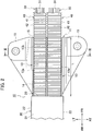
- Fig. 2 is a plan view of the main portion of the wire harness protector 10.
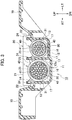
- Fig. 3 is a cross-sectional view taken along the line III-III in Fig. 2 .
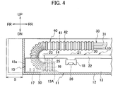
- Fig. 4 is a cross-sectional view illustrating a state where the wire harness protector 10 is accommodated in a packing box.
- Figs. 2 and 3 illustrate a state where a corrugated tube 40 extends forward without being folded (a state where the wire harness protector 10 is mounted on a vehicle).
- the directions of right, left, up, down, front, and rear are denoted by RT, LT, UP, DN, FR, and RR, respectively.
- the wire harness protector 10 includes a protector body 11 made of synthetic resin and a cover 20 made of synthetic resin.
- the protector body 11 has a bottom wall 12 and both side walls 13.
- the protector body 11 accommodates two large and small corrugated tubes 40 through which the wire harnesses 30 are inserted respectively.
- the cover 20 covers an opening 14 between upper ends 13a of the both side walls 13 of the protector body 11.
- the protector body 11 has a pair of tube chambers 13A partitioned with a partition wall 13b.
- the partition wall 13b is formed integrally projecting from the bottom wall 12 between the both side walls 13.
- the tube chambers 13A extend in parallel in a longitudinal direction (front-rear direction).
- the corrugated tubes 40 extending in the front-rear direction and through which the wire harnesses 30 are inserted respectively are accommodated in the tube chambers 13A respectively.
- the cover 20 has a ceiling wall 21, both side walls 22 which cover the both side walls 13 of the protector body 11, and a front end 23 bridged between ends of the both side walls 22 and located at a front side of the cover 20.
- the front end 23 of the cover 20 is located rearward of a front end 15 of the protector body 11 located at a front side of the protector body 11. That is, as illustrated in Figs. 1 and 2 , the total length of the cover 20 is shorter than the total length of the protector body 11.
- the front end 23 of the cover 20 is arranged at a position rearward of the front end 15 of the protector body 11 by a length L.
- a plurality (three in the embodiment) of arc plate-shaped ribs 25 and a plurality (three in the embodiment) of arc plate-shaped ribs 16 which engage with annular concave portions 41 of a convexo-concave outer surface of the corrugated tube 40 and hold the corrugated tube 40 are respectively formed in the front end 23 of the cover 20 and the portion of each tube chamber 13A of the protector body 11 facing the front end 23.
- the front end 23 of the cover 20 is formed with recesses 24 into which the upper ends 13a of the side walls 13 of the protector body 11 and the upper end of the partition wall 13b are fitted respectively.
- a plurality (three in the embodiment) of pairs of left and right protrusions 17 serving also as reinforcing ribs which lock annular convex portions 42 of the convexo-concave outer surface of the corrugated tube 40 and hold the corrugated tube 40 are integrally formed at a predetermined distance at the portions (located rearward of the front end 15) of each tube chamber 13A between the front end 15 of the protector body 11 and the front end 23 of the cover 20.
- the two corrugated tubes 40 are accommodated in the wire harness protector 10, as illustrated in Fig. 2 , the two corrugated tubes 40 are accommodated in the tube chambers 11A of the protector body 13 respectively so as to extend forward and are arranged so as to be exposed from the opening 14 between the upper ends 13a of the both side walls 13 of the protector body 11 located forward of the front end 23 of the cover 20.
- the wire harness protector 10 is accommodated in the packing box 50 for transportation, as illustrated in Fig. 4
- the two corrugated tubes 40 in the state illustrated in Fig. 2 are respectively folded (bent) outward and upward of the protector body 11 so as to extend rearward from the ribs 16 and 25 along the ceiling wall 21 of the cover 20.
- the protector body 11 is accommodated in the packaging box 50 of a smaller size than the conventional one by a portion (the conventional projection length of S) in which the folded portions of the corrugated tubes 40 do not project forward from an end face 15a of the front end 15 of the protector body 11.
- frame-shaped engagement portions 18 are integrally formed on the left and right sides of the both side walls 13 of the protector body 11.
- a plurality of mounting brackets 19 to be mounted to a vehicle body or the like are integrally formed on the right and left sides of both side walls 13 of the protector body 11.
- Hook-shaped engaging claws (locking portion) 26 to be engaged with and disengaged from the frame-shaped engaging portions 18 of the protector body 11 are integrally formed on the both side walls 22 of the cover 20 so as to project therefrom.
- the wire harnesses 30 include bundled electric wires 31 respectively.
- the two corrugated tubes 40 exposed from the opening 14 between the both side walls 13 of the protector body 11 located forward of the front end 23 of the cover 20 are accommodated in the packing box 50 for transportation of wire harnesses in the state where the two corrugated tubes 40 are respectively folded outward and upward of the protector body 11 from the front end 23 of the cover 20 along the ceiling wall 21.
- the wire harness protector 10 can be accommodated and conveyed in the packing box 50 of a smaller size than the conventional one by the amount that the folded portions of the corrugated tubes 40 do not project forward from the end face 15a of the front end 15 of the protector body 11, that is, by the projecting length S of the folded portion of the conventional corrugated tube.
- the wire harness protector 10 having a size extending to a route regulating portion necessary for securing the vehicle mounting performance can be accommodated in the packing box 50 smaller than the conventional packing box, the transportation and storage costs can be significantly reduced. Thus, low cost products can be achieved.
- the protrusions 17 for holding the corrugated tubes 40 are formed at the portions rearward of the front end 15 of the protector body 11 and forward of the ribs 16, 25.
- the movement of the corrugated tubes 40 in the front-rear direction can be easily and reliably regulated after the corrugated tubes 40 are mounted on the vehicle.
- the protector body 11 has the pair of tube chambers 13A which accommodate the two large and small corrugated tubes 40 respectively and the two large and small corrugated tubes 40 are folded outward and upward of the protector body 11 from the front end 23 of the cover 20 along the ceiling wall 21.
- the corrugated tubes 40 through which the wire harnesses 30 are inserted can be held by the ribs 16, 25 in a form matching the specifications, and can be easily and reliably folded.
- the ribs 16 and the ribs 25 provided to face each other improve the foldability of the corrugated tubes 40 when the corrugated tubes 40 through which the wire harnesses 30 are inserted are folded outward and upward of the protector body 11.
- the amount of the corrugated tubes 40 projecting forward and upward can be suppressed more than when there is no rib.
- the protector body 11 having the size extending to the route regulating portion necessary for securing the vehicle mounting performance can be accommodated in the small-sized packing box 50 with a simple structure in which the front end 23 of the cover 20 is located rearward of the front end 15 of the protector body 11. Therefore, the protector body 11 having a simple structure same as the conventional one or a simpler structure more than the conventional one can be used and the costs can be reduced accordingly.
- the cover 20 is formed to have the length shorter than the length of the protector body 11 so that the front end 23 of the cover 20 is located rearward of the front end 15 of the protector body 11 and the corrugated tubes 40 do not project forward from the front end 15 of the protector body 11 when the corrugated tubes 40 are folded from the front end 23 of the cover 20.
- a rectangular recess may be formed rearward from the forward end of the cover 20 formed to have the same length as the protector body 11 and the corrugated tubes 40 may be folded from the edge end of the recess as the front end 23 of the cover 20. Even in this case, the corrugated tubes 40 can be prevented from projecting forward from the front end 15 of the protector body 11.
- the front end 23 of the cover 20 is formed to be located rearward of the front end 15 of the protector body 11.
- the front end 15 of the protector body 11 may be formed to be located rearward of the front end 23 of the cover 20.
- the protrusions 17 are formed at portions located rearward of the front end 23 of the cover 20 and the corrugated tubes 40 are folded outward at the front end 15 of the protector body 11.
- the pair of tube chambers 13A which accommodate the two corrugated tubes 40 are formed in the protector body 11.
- one tube chamber which accommodates one corrugated tube or three or more tube chambers which accommodate three or more corrugated tubes may be formed in the protector body 11.
Landscapes
- Engineering & Computer Science (AREA)
- Architecture (AREA)
- Civil Engineering (AREA)
- Structural Engineering (AREA)
- Mechanical Engineering (AREA)
- Details Of Indoor Wiring (AREA)
Abstract
Description
- The present invention is related to a wire harness protector that fixes a corrugated tube through which a wire harness is inserted to accommodate the corrugated tube in a packing box.
- Japanese Utility Model Application Publication No.
H5-25919 - The route of the corrugated tube is regulated by using the wire harness protector in order to secure a vehicle mounting performance of the wire harness. On the other hand, when the wire harness protector is transported to a factory or the like where the wire harness protector is mounted on a vehicle, the wire harness protector is accommodated in a packing box with the corrugated tube exposed from the front end of the protector body being folded outward and upward along the front end of the protector body.
- When the wire harness protector is accommodated in the packing box, the corrugated tube is folded in a state of being largely projected outward from the front end of the protector body. Therefore, the size of the packing box for transportation of the wire harness is increased, the amount to be transported is increased, and a large storage space is required. Thus the costs are increased accordingly.
- An object of the present invention is to provide a wire harness protector that is capable of reducing transportation costs and storage costs.
- A wire harness protector in accordance with the present invention includes: a protector body configured to accommodate a corrugated tube extending in a front-rear direction and through which a wire harness is inserted; and a cover configured to cover an opening of the protector body. A first front end being one of a front end of the protector body or a front end of the cover is arranged rearward of a second front end being the other of the front ends. A portion of the wire harness protector located at the first front end includes a first rib configured to hold the corrugated tube. A portion of the wire harness protector facing the first front end and located rearward of the second front end includes a second rib configured to hold the corrugated tube.
- According to the above configuration, the corrugated tube through which the wire harness is inserted is projected outward of the protector body from the first front end being one of the front ends of the protector body and the cover that is located rearward without being projected outward of the protector body from the second front end being the other of the front ends that is located forward. Therefore, the wire harness protector can be accommodated in a packing box smaller than the packing box for the conventional wire harness protector, whereby transportation costs and storage costs are reduced accordingly to achieve low cost products.
-
-
Fig. 1 is a perspective view of a main portion of a wire harness protector according to an embodiment of the present invention. -
Fig. 2 is a plan view of the main portion of the wire harness protector illustrated inFig. 1 . -
Fig. 3 is a cross-sectional view taken along the line III-III inFig. 2 . -
Fig. 4 is a cross-sectional view illustrating a state where the wire harness protector illustrated inFig. 1 is accommodated in a packing box. - Description will be hereinbelow provided for an embodiment of the present invention by referring to the drawings.
-
Fig. 1 is a perspective view of a main portion of awire harness protector 10 according to an embodiment of the present invention.Fig. 2 is a plan view of the main portion of thewire harness protector 10.Fig. 3 is a cross-sectional view taken along the line III-III inFig. 2 .Fig. 4 is a cross-sectional view illustrating a state where thewire harness protector 10 is accommodated in a packing box.Figs. 2 and3 illustrate a state where acorrugated tube 40 extends forward without being folded (a state where thewire harness protector 10 is mounted on a vehicle). InFigs. 1 to 4 , the directions of right, left, up, down, front, and rear are denoted by RT, LT, UP, DN, FR, and RR, respectively. - As illustrated in
Figs. 1 to 4 , thewire harness protector 10 includes aprotector body 11 made of synthetic resin and acover 20 made of synthetic resin. Theprotector body 11 has abottom wall 12 and bothside walls 13. Theprotector body 11 accommodates two large and smallcorrugated tubes 40 through which thewire harnesses 30 are inserted respectively. Thecover 20 covers an opening 14 betweenupper ends 13a of the bothside walls 13 of theprotector body 11. - As illustrated in
Figs. 1 to 3 , theprotector body 11 has a pair oftube chambers 13A partitioned with apartition wall 13b. Thepartition wall 13b is formed integrally projecting from thebottom wall 12 between the bothside walls 13. Thetube chambers 13A extend in parallel in a longitudinal direction (front-rear direction). Thecorrugated tubes 40 extending in the front-rear direction and through which thewire harnesses 30 are inserted respectively are accommodated in thetube chambers 13A respectively. - As illustrated in
Figs. 1 and3 , thecover 20 has aceiling wall 21, bothside walls 22 which cover the bothside walls 13 of theprotector body 11, and afront end 23 bridged between ends of the bothside walls 22 and located at a front side of thecover 20. Thefront end 23 of thecover 20 is located rearward of afront end 15 of theprotector body 11 located at a front side of theprotector body 11. That is, as illustrated inFigs. 1 and2 , the total length of thecover 20 is shorter than the total length of theprotector body 11. Thefront end 23 of thecover 20 is arranged at a position rearward of thefront end 15 of theprotector body 11 by a length L. - As illustrated in
Figs. 1 to 3 , a plurality (three in the embodiment) of arc plate-shaped ribs 25 and a plurality (three in the embodiment) of arc plate-shaped ribs 16 which engage with annularconcave portions 41 of a convexo-concave outer surface of thecorrugated tube 40 and hold thecorrugated tube 40 are respectively formed in thefront end 23 of thecover 20 and the portion of eachtube chamber 13A of theprotector body 11 facing thefront end 23. Thefront end 23 of thecover 20 is formed withrecesses 24 into which theupper ends 13a of theside walls 13 of theprotector body 11 and the upper end of thepartition wall 13b are fitted respectively. - As illustrated in
Fig. 1 , a plurality (three in the embodiment) of pairs of left andright protrusions 17 serving also as reinforcing ribs which lock annularconvex portions 42 of the convexo-concave outer surface of thecorrugated tube 40 and hold thecorrugated tube 40 are integrally formed at a predetermined distance at the portions (located rearward of the front end 15) of eachtube chamber 13A between thefront end 15 of theprotector body 11 and thefront end 23 of thecover 20. - When the two
corrugated tubes 40 are accommodated in thewire harness protector 10, as illustrated inFig. 2 , the twocorrugated tubes 40 are accommodated in the tube chambers 11A of theprotector body 13 respectively so as to extend forward and are arranged so as to be exposed from theopening 14 between theupper ends 13a of the bothside walls 13 of theprotector body 11 located forward of thefront end 23 of thecover 20. When thewire harness protector 10 is accommodated in thepacking box 50 for transportation, as illustrated inFig. 4 , the twocorrugated tubes 40 in the state illustrated inFig. 2 are respectively folded (bent) outward and upward of theprotector body 11 so as to extend rearward from theribs ceiling wall 21 of thecover 20. In this state, theprotector body 11 is accommodated in thepackaging box 50 of a smaller size than the conventional one by a portion (the conventional projection length of S) in which the folded portions of thecorrugated tubes 40 do not project forward from anend face 15a of thefront end 15 of theprotector body 11. - As illustrated in
Fig. 1 , frame-shaped engagement portions 18 are integrally formed on the left and right sides of the bothside walls 13 of theprotector body 11. A plurality ofmounting brackets 19 to be mounted to a vehicle body or the like are integrally formed on the right and left sides of bothside walls 13 of theprotector body 11. Hook-shaped engaging claws (locking portion) 26 to be engaged with and disengaged from the frame-shapedengaging portions 18 of theprotector body 11 are integrally formed on the bothside walls 22 of thecover 20 so as to project therefrom. As illustrated inFigs. 2 and4 , thewire harnesses 30 include bundledelectric wires 31 respectively. - According to the embodiment, as illustrated in
Fig. 4 , the twocorrugated tubes 40 exposed from theopening 14 between the bothside walls 13 of theprotector body 11 located forward of thefront end 23 of thecover 20 are accommodated in thepacking box 50 for transportation of wire harnesses in the state where the twocorrugated tubes 40 are respectively folded outward and upward of theprotector body 11 from thefront end 23 of thecover 20 along theceiling wall 21. As a result, thewire harness protector 10 can be accommodated and conveyed in thepacking box 50 of a smaller size than the conventional one by the amount that the folded portions of thecorrugated tubes 40 do not project forward from theend face 15a of thefront end 15 of theprotector body 11, that is, by the projecting length S of the folded portion of the conventional corrugated tube. Thus, since thewire harness protector 10 having a size extending to a route regulating portion necessary for securing the vehicle mounting performance can be accommodated in thepacking box 50 smaller than the conventional packing box, the transportation and storage costs can be significantly reduced. Thus, low cost products can be achieved. - According to the embodiment, the
protrusions 17 for holding thecorrugated tubes 40 are formed at the portions rearward of thefront end 15 of theprotector body 11 and forward of theribs Figs. 2 and3 , the movement of thecorrugated tubes 40 in the front-rear direction can be easily and reliably regulated after thecorrugated tubes 40 are mounted on the vehicle. - According to the embodiment, the
protector body 11 has the pair oftube chambers 13A which accommodate the two large and smallcorrugated tubes 40 respectively and the two large and smallcorrugated tubes 40 are folded outward and upward of theprotector body 11 from thefront end 23 of thecover 20 along theceiling wall 21. Thus, thecorrugated tubes 40 through which thewire harnesses 30 are inserted can be held by theribs ribs 16 and theribs 25 provided to face each other improve the foldability of thecorrugated tubes 40 when thecorrugated tubes 40 through which thewire harnesses 30 are inserted are folded outward and upward of theprotector body 11. Thus, the amount of thecorrugated tubes 40 projecting forward and upward can be suppressed more than when there is no rib. - According to the embodiment, the
protector body 11 having the size extending to the route regulating portion necessary for securing the vehicle mounting performance can be accommodated in the small-sized packing box 50 with a simple structure in which thefront end 23 of thecover 20 is located rearward of thefront end 15 of theprotector body 11. Therefore, theprotector body 11 having a simple structure same as the conventional one or a simpler structure more than the conventional one can be used and the costs can be reduced accordingly. - In the embodiment, the
cover 20 is formed to have the length shorter than the length of theprotector body 11 so that thefront end 23 of thecover 20 is located rearward of thefront end 15 of theprotector body 11 and thecorrugated tubes 40 do not project forward from thefront end 15 of theprotector body 11 when thecorrugated tubes 40 are folded from thefront end 23 of thecover 20. However, for example, a rectangular recess may be formed rearward from the forward end of thecover 20 formed to have the same length as theprotector body 11 and thecorrugated tubes 40 may be folded from the edge end of the recess as thefront end 23 of thecover 20. Even in this case, thecorrugated tubes 40 can be prevented from projecting forward from thefront end 15 of theprotector body 11. - In the embodiment, the
front end 23 of thecover 20 is formed to be located rearward of thefront end 15 of theprotector body 11. However, for example, thefront end 15 of theprotector body 11 may be formed to be located rearward of thefront end 23 of thecover 20. In this case, theprotrusions 17 are formed at portions located rearward of thefront end 23 of thecover 20 and thecorrugated tubes 40 are folded outward at thefront end 15 of theprotector body 11. - In the embodiment, the pair of
tube chambers 13A which accommodate the twocorrugated tubes 40 are formed in theprotector body 11. However, for example, one tube chamber which accommodates one corrugated tube or three or more tube chambers which accommodate three or more corrugated tubes may be formed in theprotector body 11. - Although the present invention has been described above by reference to the embodiment, the present invention is not limited to those and the configuration of parts can be replaced with any configuration having a similar function, as long as they lie within the scope of the claims.
Claims (5)
- A wire harness protector comprising:a protector body configured to accommodate a corrugated tube extending in a front-rear direction and through which a wire harness is inserted; anda cover configured to cover an opening of the protector body, whereina first front end being one of a front end of the protector body or a front end of the cover is arranged rearward of a second front end being the other of the front ends,a portion of the wire harness protector located at the first front end includes a first rib configured to hold the corrugated tube, anda portion of the wire harness protector facing the first front end and located rearward of the second front end includes a second rib configured to hold the corrugated tube.
- The wire harness protector according to claim 1, wherein a portion of the wire harness protector between the second rib and the second front end includes at least one protrusion configured to hold the corrugated tube.
- The wire harness protector according to claim 1 or 2, wherein the protector body has a tube chamber configured to accommodate at least two of the corrugated tubes each folded from the first front end toward an outside of the protector body.
- The wire harness protector according to any one of claims 1 to 3, wherein
the first front end is the front end of the cover, and
the second front end is the front end of the protector body. - The wire harness protector according to claim 3, wherein the protector body with the at least two of the corrugated tubes each folded from the first front end toward the outside of the protector body is accommodatable in a packing box.
Applications Claiming Priority (1)
| Application Number | Priority Date | Filing Date | Title |
|---|---|---|---|
| JP2019145895A JP7144377B2 (en) | 2019-08-08 | 2019-08-08 | Wire harness protector |
Publications (2)
| Publication Number | Publication Date |
|---|---|
| EP3772435A1 true EP3772435A1 (en) | 2021-02-10 |
| EP3772435B1 EP3772435B1 (en) | 2022-03-09 |
Family
ID=71950442
Family Applications (1)
| Application Number | Title | Priority Date | Filing Date |
|---|---|---|---|
| EP20189500.0A Active EP3772435B1 (en) | 2019-08-08 | 2020-08-05 | Wire harness protector |
Country Status (4)
| Country | Link |
|---|---|
| US (1) | US11192510B2 (en) |
| EP (1) | EP3772435B1 (en) |
| JP (1) | JP7144377B2 (en) |
| CN (1) | CN112350252B (en) |
Citations (5)
| Publication number | Priority date | Publication date | Assignee | Title |
|---|---|---|---|---|
| JPH118922A (en) * | 1997-06-17 | 1999-01-12 | Yazaki Corp | Protector |
| US20010004022A1 (en) * | 1999-12-14 | 2001-06-21 | Sumitomo Wiring Systems, Ltd. | Harness-wiring system for a sliding door of vechicles |
| US20050217888A1 (en) * | 2004-04-02 | 2005-10-06 | Yazaki Corporation | Wire harness protector |
| US7692095B2 (en) * | 2007-08-21 | 2010-04-06 | Yazaki Corporation | Wire harness lead-out structure of protector |
| US9270101B2 (en) * | 2010-10-22 | 2016-02-23 | Sumitomo Wiring Systems, Ltd. | Outer cover structure for wire harness |
Family Cites Families (12)
| Publication number | Priority date | Publication date | Assignee | Title |
|---|---|---|---|---|
| JPH0525919U (en) * | 1991-09-11 | 1993-04-02 | 矢崎総業株式会社 | Striatal protector |
| JP2002135941A (en) * | 2000-10-23 | 2002-05-10 | Yazaki Corp | Wire harness protector |
| JP4256764B2 (en) * | 2003-12-05 | 2009-04-22 | 矢崎総業株式会社 | Harness guide protector, wire surplus length absorption structure including the same, and harness guide protector fixing method |
| JP5074757B2 (en) * | 2006-12-19 | 2012-11-14 | 矢崎総業株式会社 | Power feeding device and harness wiring structure using the same |
| JP5084019B2 (en) * | 2007-08-21 | 2012-11-28 | 矢崎総業株式会社 | Wire harness protector |
| JP5353654B2 (en) * | 2009-11-18 | 2013-11-27 | 住友電装株式会社 | Protector for wire harness |
| CN201781231U (en) * | 2010-08-27 | 2011-03-30 | 宁波诗兰姆汽车零部件有限公司 | Locking structure for automobile wire harness shunt protection binding button and socket connector protection casing |
| JP5755932B2 (en) * | 2011-04-19 | 2015-07-29 | 矢崎総業株式会社 | Protector and protector arrangement structure |
| JP6329829B2 (en) * | 2014-07-10 | 2018-05-23 | 矢崎総業株式会社 | Corrugated tube fixing structure |
| JP2016119740A (en) | 2014-12-18 | 2016-06-30 | 住友電装株式会社 | Protector and wiring harness |
| JP6092182B2 (en) * | 2014-12-25 | 2017-03-08 | 矢崎総業株式会社 | Sliding protector |
| JP6762285B2 (en) * | 2017-10-20 | 2020-09-30 | 矢崎総業株式会社 | Protector for wire harness and manufacturing method of wire harness |
-
2019
- 2019-08-08 JP JP2019145895A patent/JP7144377B2/en active Active
-
2020
- 2020-08-05 EP EP20189500.0A patent/EP3772435B1/en active Active
- 2020-08-06 CN CN202010784773.9A patent/CN112350252B/en active Active
- 2020-08-06 US US16/986,528 patent/US11192510B2/en active Active
Patent Citations (5)
| Publication number | Priority date | Publication date | Assignee | Title |
|---|---|---|---|---|
| JPH118922A (en) * | 1997-06-17 | 1999-01-12 | Yazaki Corp | Protector |
| US20010004022A1 (en) * | 1999-12-14 | 2001-06-21 | Sumitomo Wiring Systems, Ltd. | Harness-wiring system for a sliding door of vechicles |
| US20050217888A1 (en) * | 2004-04-02 | 2005-10-06 | Yazaki Corporation | Wire harness protector |
| US7692095B2 (en) * | 2007-08-21 | 2010-04-06 | Yazaki Corporation | Wire harness lead-out structure of protector |
| US9270101B2 (en) * | 2010-10-22 | 2016-02-23 | Sumitomo Wiring Systems, Ltd. | Outer cover structure for wire harness |
Also Published As
| Publication number | Publication date |
|---|---|
| JP2021027759A (en) | 2021-02-22 |
| US20210039571A1 (en) | 2021-02-11 |
| JP7144377B2 (en) | 2022-09-29 |
| US11192510B2 (en) | 2021-12-07 |
| EP3772435B1 (en) | 2022-03-09 |
| CN112350252B (en) | 2021-12-24 |
| CN112350252A (en) | 2021-02-09 |
Similar Documents
| Publication | Publication Date | Title |
|---|---|---|
| US8124887B2 (en) | Protector | |
| EP1363375B1 (en) | Wire harness protector | |
| US7038133B2 (en) | Wire harness protector | |
| JP6548038B2 (en) | connector | |
| JP6879474B2 (en) | Harness protector and harness assembly | |
| WO2019103030A1 (en) | Wiring harness protector and harness assembly | |
| EP0885780A2 (en) | A bracket locking clamp | |
| EP0731533B1 (en) | Electrical connection box | |
| WO2015056551A1 (en) | Protector for wire harness | |
| US7390967B2 (en) | Binding band-fixing structure | |
| CN102751679B (en) | Electric wire chuck constructs | |
| JP4494939B2 (en) | Holder clip | |
| CN107534279A (en) | Cable holder protector | |
| EP3772435B1 (en) | Wire harness protector | |
| JP6431883B2 (en) | connector | |
| JP4569448B2 (en) | connector | |
| US20180186313A1 (en) | Wire housing protector | |
| CN108370117B (en) | connector structure | |
| EP3796477B1 (en) | Electric wire cover | |
| US6967286B2 (en) | Lock structure | |
| JP6653288B2 (en) | Grommet | |
| JP5923260B2 (en) | Protector and lock method of the protector | |
| CN103620238A (en) | Clip | |
| JP3915645B2 (en) | Wire harness protector | |
| CN107112683A (en) | Connector |
Legal Events
| Date | Code | Title | Description |
|---|---|---|---|
| PUAI | Public reference made under article 153(3) epc to a published international application that has entered the european phase |
Free format text: ORIGINAL CODE: 0009012 |
|
| STAA | Information on the status of an ep patent application or granted ep patent |
Free format text: STATUS: REQUEST FOR EXAMINATION WAS MADE |
|
| 17P | Request for examination filed |
Effective date: 20200805 |
|
| AK | Designated contracting states |
Kind code of ref document: A1 Designated state(s): AL AT BE BG CH CY CZ DE DK EE ES FI FR GB GR HR HU IE IS IT LI LT LU LV MC MK MT NL NO PL PT RO RS SE SI SK SM TR |
|
| AX | Request for extension of the european patent |
Extension state: BA ME |
|
| RBV | Designated contracting states (corrected) |
Designated state(s): AL AT BE BG CH CY CZ DE DK EE ES FI FR GB GR HR HU IE IS IT LI LT LU LV MC MK MT NL NO PL PT RO RS SE SI SK SM TR |
|
| STAA | Information on the status of an ep patent application or granted ep patent |
Free format text: STATUS: EXAMINATION IS IN PROGRESS |
|
| 17Q | First examination report despatched |
Effective date: 20210817 |
|
| GRAP | Despatch of communication of intention to grant a patent |
Free format text: ORIGINAL CODE: EPIDOSNIGR1 |
|
| STAA | Information on the status of an ep patent application or granted ep patent |
Free format text: STATUS: GRANT OF PATENT IS INTENDED |
|
| INTG | Intention to grant announced |
Effective date: 20211222 |
|
| GRAS | Grant fee paid |
Free format text: ORIGINAL CODE: EPIDOSNIGR3 |
|
| GRAA | (expected) grant |
Free format text: ORIGINAL CODE: 0009210 |
|
| STAA | Information on the status of an ep patent application or granted ep patent |
Free format text: STATUS: THE PATENT HAS BEEN GRANTED |
|
| AK | Designated contracting states |
Kind code of ref document: B1 Designated state(s): AL AT BE BG CH CY CZ DE DK EE ES FI FR GB GR HR HU IE IS IT LI LT LU LV MC MK MT NL NO PL PT RO RS SE SI SK SM TR |
|
| REG | Reference to a national code |
Ref country code: CH Ref legal event code: EP Ref country code: AT Ref legal event code: REF Ref document number: 1473885 Country of ref document: AT Kind code of ref document: T Effective date: 20220315 |
|
| REG | Reference to a national code |
Ref country code: IE Ref legal event code: FG4D |
|
| REG | Reference to a national code |
Ref country code: DE Ref legal event code: R096 Ref document number: 602020002145 Country of ref document: DE |
|
| REG | Reference to a national code |
Ref country code: LT Ref legal event code: MG9D |
|
| REG | Reference to a national code |
Ref country code: NL Ref legal event code: MP Effective date: 20220309 |
|
| PG25 | Lapsed in a contracting state [announced via postgrant information from national office to epo] |
Ref country code: SE Free format text: LAPSE BECAUSE OF FAILURE TO SUBMIT A TRANSLATION OF THE DESCRIPTION OR TO PAY THE FEE WITHIN THE PRESCRIBED TIME-LIMIT Effective date: 20220309 Ref country code: RS Free format text: LAPSE BECAUSE OF FAILURE TO SUBMIT A TRANSLATION OF THE DESCRIPTION OR TO PAY THE FEE WITHIN THE PRESCRIBED TIME-LIMIT Effective date: 20220309 Ref country code: NO Free format text: LAPSE BECAUSE OF FAILURE TO SUBMIT A TRANSLATION OF THE DESCRIPTION OR TO PAY THE FEE WITHIN THE PRESCRIBED TIME-LIMIT Effective date: 20220609 Ref country code: LT Free format text: LAPSE BECAUSE OF FAILURE TO SUBMIT A TRANSLATION OF THE DESCRIPTION OR TO PAY THE FEE WITHIN THE PRESCRIBED TIME-LIMIT Effective date: 20220309 Ref country code: HR Free format text: LAPSE BECAUSE OF FAILURE TO SUBMIT A TRANSLATION OF THE DESCRIPTION OR TO PAY THE FEE WITHIN THE PRESCRIBED TIME-LIMIT Effective date: 20220309 Ref country code: BG Free format text: LAPSE BECAUSE OF FAILURE TO SUBMIT A TRANSLATION OF THE DESCRIPTION OR TO PAY THE FEE WITHIN THE PRESCRIBED TIME-LIMIT Effective date: 20220609 |
|
| REG | Reference to a national code |
Ref country code: AT Ref legal event code: MK05 Ref document number: 1473885 Country of ref document: AT Kind code of ref document: T Effective date: 20220309 |
|
| PG25 | Lapsed in a contracting state [announced via postgrant information from national office to epo] |
Ref country code: LV Free format text: LAPSE BECAUSE OF FAILURE TO SUBMIT A TRANSLATION OF THE DESCRIPTION OR TO PAY THE FEE WITHIN THE PRESCRIBED TIME-LIMIT Effective date: 20220309 Ref country code: GR Free format text: LAPSE BECAUSE OF FAILURE TO SUBMIT A TRANSLATION OF THE DESCRIPTION OR TO PAY THE FEE WITHIN THE PRESCRIBED TIME-LIMIT Effective date: 20220610 Ref country code: FI Free format text: LAPSE BECAUSE OF FAILURE TO SUBMIT A TRANSLATION OF THE DESCRIPTION OR TO PAY THE FEE WITHIN THE PRESCRIBED TIME-LIMIT Effective date: 20220309 |
|
| PG25 | Lapsed in a contracting state [announced via postgrant information from national office to epo] |
Ref country code: NL Free format text: LAPSE BECAUSE OF FAILURE TO SUBMIT A TRANSLATION OF THE DESCRIPTION OR TO PAY THE FEE WITHIN THE PRESCRIBED TIME-LIMIT Effective date: 20220309 |
|
| PG25 | Lapsed in a contracting state [announced via postgrant information from national office to epo] |
Ref country code: SM Free format text: LAPSE BECAUSE OF FAILURE TO SUBMIT A TRANSLATION OF THE DESCRIPTION OR TO PAY THE FEE WITHIN THE PRESCRIBED TIME-LIMIT Effective date: 20220309 Ref country code: SK Free format text: LAPSE BECAUSE OF FAILURE TO SUBMIT A TRANSLATION OF THE DESCRIPTION OR TO PAY THE FEE WITHIN THE PRESCRIBED TIME-LIMIT Effective date: 20220309 Ref country code: RO Free format text: LAPSE BECAUSE OF FAILURE TO SUBMIT A TRANSLATION OF THE DESCRIPTION OR TO PAY THE FEE WITHIN THE PRESCRIBED TIME-LIMIT Effective date: 20220309 Ref country code: PT Free format text: LAPSE BECAUSE OF FAILURE TO SUBMIT A TRANSLATION OF THE DESCRIPTION OR TO PAY THE FEE WITHIN THE PRESCRIBED TIME-LIMIT Effective date: 20220711 Ref country code: ES Free format text: LAPSE BECAUSE OF FAILURE TO SUBMIT A TRANSLATION OF THE DESCRIPTION OR TO PAY THE FEE WITHIN THE PRESCRIBED TIME-LIMIT Effective date: 20220309 Ref country code: EE Free format text: LAPSE BECAUSE OF FAILURE TO SUBMIT A TRANSLATION OF THE DESCRIPTION OR TO PAY THE FEE WITHIN THE PRESCRIBED TIME-LIMIT Effective date: 20220309 Ref country code: CZ Free format text: LAPSE BECAUSE OF FAILURE TO SUBMIT A TRANSLATION OF THE DESCRIPTION OR TO PAY THE FEE WITHIN THE PRESCRIBED TIME-LIMIT Effective date: 20220309 Ref country code: AT Free format text: LAPSE BECAUSE OF FAILURE TO SUBMIT A TRANSLATION OF THE DESCRIPTION OR TO PAY THE FEE WITHIN THE PRESCRIBED TIME-LIMIT Effective date: 20220309 |
|
| PG25 | Lapsed in a contracting state [announced via postgrant information from national office to epo] |
Ref country code: PL Free format text: LAPSE BECAUSE OF FAILURE TO SUBMIT A TRANSLATION OF THE DESCRIPTION OR TO PAY THE FEE WITHIN THE PRESCRIBED TIME-LIMIT Effective date: 20220309 Ref country code: IS Free format text: LAPSE BECAUSE OF FAILURE TO SUBMIT A TRANSLATION OF THE DESCRIPTION OR TO PAY THE FEE WITHIN THE PRESCRIBED TIME-LIMIT Effective date: 20220709 Ref country code: AL Free format text: LAPSE BECAUSE OF FAILURE TO SUBMIT A TRANSLATION OF THE DESCRIPTION OR TO PAY THE FEE WITHIN THE PRESCRIBED TIME-LIMIT Effective date: 20220309 |
|
| REG | Reference to a national code |
Ref country code: DE Ref legal event code: R097 Ref document number: 602020002145 Country of ref document: DE |
|
| PLBE | No opposition filed within time limit |
Free format text: ORIGINAL CODE: 0009261 |
|
| STAA | Information on the status of an ep patent application or granted ep patent |
Free format text: STATUS: NO OPPOSITION FILED WITHIN TIME LIMIT |
|
| PG25 | Lapsed in a contracting state [announced via postgrant information from national office to epo] |
Ref country code: DK Free format text: LAPSE BECAUSE OF FAILURE TO SUBMIT A TRANSLATION OF THE DESCRIPTION OR TO PAY THE FEE WITHIN THE PRESCRIBED TIME-LIMIT Effective date: 20220309 |
|
| 26N | No opposition filed |
Effective date: 20221212 |
|
| PG25 | Lapsed in a contracting state [announced via postgrant information from national office to epo] |
Ref country code: SI Free format text: LAPSE BECAUSE OF FAILURE TO SUBMIT A TRANSLATION OF THE DESCRIPTION OR TO PAY THE FEE WITHIN THE PRESCRIBED TIME-LIMIT Effective date: 20220309 |
|
| PG25 | Lapsed in a contracting state [announced via postgrant information from national office to epo] |
Ref country code: MC Free format text: LAPSE BECAUSE OF FAILURE TO SUBMIT A TRANSLATION OF THE DESCRIPTION OR TO PAY THE FEE WITHIN THE PRESCRIBED TIME-LIMIT Effective date: 20220309 |
|
| PG25 | Lapsed in a contracting state [announced via postgrant information from national office to epo] |
Ref country code: LU Free format text: LAPSE BECAUSE OF NON-PAYMENT OF DUE FEES Effective date: 20220805 |
|
| REG | Reference to a national code |
Ref country code: BE Ref legal event code: MM Effective date: 20220831 |
|
| PG25 | Lapsed in a contracting state [announced via postgrant information from national office to epo] |
Ref country code: IT Free format text: LAPSE BECAUSE OF FAILURE TO SUBMIT A TRANSLATION OF THE DESCRIPTION OR TO PAY THE FEE WITHIN THE PRESCRIBED TIME-LIMIT Effective date: 20220309 Ref country code: IE Free format text: LAPSE BECAUSE OF NON-PAYMENT OF DUE FEES Effective date: 20220805 Ref country code: FR Free format text: LAPSE BECAUSE OF NON-PAYMENT OF DUE FEES Effective date: 20220831 |
|
| PG25 | Lapsed in a contracting state [announced via postgrant information from national office to epo] |
Ref country code: BE Free format text: LAPSE BECAUSE OF NON-PAYMENT OF DUE FEES Effective date: 20220831 |
|
| REG | Reference to a national code |
Ref country code: CH Ref legal event code: PL |
|
| PG25 | Lapsed in a contracting state [announced via postgrant information from national office to epo] |
Ref country code: CY Free format text: LAPSE BECAUSE OF FAILURE TO SUBMIT A TRANSLATION OF THE DESCRIPTION OR TO PAY THE FEE WITHIN THE PRESCRIBED TIME-LIMIT Effective date: 20220309 Ref country code: CH Free format text: LAPSE BECAUSE OF NON-PAYMENT OF DUE FEES Effective date: 20230831 |
|
| PG25 | Lapsed in a contracting state [announced via postgrant information from national office to epo] |
Ref country code: MK Free format text: LAPSE BECAUSE OF FAILURE TO SUBMIT A TRANSLATION OF THE DESCRIPTION OR TO PAY THE FEE WITHIN THE PRESCRIBED TIME-LIMIT Effective date: 20220309 Ref country code: HU Free format text: LAPSE BECAUSE OF FAILURE TO SUBMIT A TRANSLATION OF THE DESCRIPTION OR TO PAY THE FEE WITHIN THE PRESCRIBED TIME-LIMIT; INVALID AB INITIO Effective date: 20200805 |
|
| PG25 | Lapsed in a contracting state [announced via postgrant information from national office to epo] |
Ref country code: MT Free format text: LAPSE BECAUSE OF FAILURE TO SUBMIT A TRANSLATION OF THE DESCRIPTION OR TO PAY THE FEE WITHIN THE PRESCRIBED TIME-LIMIT Effective date: 20220309 |
|
| GBPC | Gb: european patent ceased through non-payment of renewal fee |
Effective date: 20240805 |
|
| PG25 | Lapsed in a contracting state [announced via postgrant information from national office to epo] |
Ref country code: GB Free format text: LAPSE BECAUSE OF NON-PAYMENT OF DUE FEES Effective date: 20240805 |
|
| PGFP | Annual fee paid to national office [announced via postgrant information from national office to epo] |
Ref country code: DE Payment date: 20250702 Year of fee payment: 6 |
|
| PG25 | Lapsed in a contracting state [announced via postgrant information from national office to epo] |
Ref country code: TR Free format text: LAPSE BECAUSE OF FAILURE TO SUBMIT A TRANSLATION OF THE DESCRIPTION OR TO PAY THE FEE WITHIN THE PRESCRIBED TIME-LIMIT Effective date: 20220309 |