EP3772392A1 - Power tool system - Google Patents
Power tool system Download PDFInfo
- Publication number
- EP3772392A1 EP3772392A1 EP20189850.9A EP20189850A EP3772392A1 EP 3772392 A1 EP3772392 A1 EP 3772392A1 EP 20189850 A EP20189850 A EP 20189850A EP 3772392 A1 EP3772392 A1 EP 3772392A1
- Authority
- EP
- European Patent Office
- Prior art keywords
- tool
- base housing
- circuit board
- battery pack
- controller
- Prior art date
- Legal status (The legal status is an assumption and is not a legal conclusion. Google has not performed a legal analysis and makes no representation as to the accuracy of the status listed.)
- Withdrawn
Links
Images
Classifications
-
- B—PERFORMING OPERATIONS; TRANSPORTING
- B25—HAND TOOLS; PORTABLE POWER-DRIVEN TOOLS; MANIPULATORS
- B25F—COMBINATION OR MULTI-PURPOSE TOOLS NOT OTHERWISE PROVIDED FOR; DETAILS OR COMPONENTS OF PORTABLE POWER-DRIVEN TOOLS NOT PARTICULARLY RELATED TO THE OPERATIONS PERFORMED AND NOT OTHERWISE PROVIDED FOR
- B25F5/00—Details or components of portable power-driven tools not particularly related to the operations performed and not otherwise provided for
-
- B—PERFORMING OPERATIONS; TRANSPORTING
- B25—HAND TOOLS; PORTABLE POWER-DRIVEN TOOLS; MANIPULATORS
- B25F—COMBINATION OR MULTI-PURPOSE TOOLS NOT OTHERWISE PROVIDED FOR; DETAILS OR COMPONENTS OF PORTABLE POWER-DRIVEN TOOLS NOT PARTICULARLY RELATED TO THE OPERATIONS PERFORMED AND NOT OTHERWISE PROVIDED FOR
- B25F5/00—Details or components of portable power-driven tools not particularly related to the operations performed and not otherwise provided for
- B25F5/02—Construction of casings, bodies or handles
-
- B—PERFORMING OPERATIONS; TRANSPORTING
- B05—SPRAYING OR ATOMISING IN GENERAL; APPLYING FLUENT MATERIALS TO SURFACES, IN GENERAL
- B05C—APPARATUS FOR APPLYING FLUENT MATERIALS TO SURFACES, IN GENERAL
- B05C17/00—Hand tools or apparatus using hand held tools, for applying liquids or other fluent materials to, for spreading applied liquids or other fluent materials on, or for partially removing applied liquids or other fluent materials from, surfaces
- B05C17/005—Hand tools or apparatus using hand held tools, for applying liquids or other fluent materials to, for spreading applied liquids or other fluent materials on, or for partially removing applied liquids or other fluent materials from, surfaces for discharging material from a reservoir or container located in or on the hand tool through an outlet orifice by pressure without using surface contacting members like pads or brushes
- B05C17/00523—Hand tools or apparatus using hand held tools, for applying liquids or other fluent materials to, for spreading applied liquids or other fluent materials on, or for partially removing applied liquids or other fluent materials from, surfaces for discharging material from a reservoir or container located in or on the hand tool through an outlet orifice by pressure without using surface contacting members like pads or brushes provided with means to heat the material
-
- B—PERFORMING OPERATIONS; TRANSPORTING
- B25—HAND TOOLS; PORTABLE POWER-DRIVEN TOOLS; MANIPULATORS
- B25F—COMBINATION OR MULTI-PURPOSE TOOLS NOT OTHERWISE PROVIDED FOR; DETAILS OR COMPONENTS OF PORTABLE POWER-DRIVEN TOOLS NOT PARTICULARLY RELATED TO THE OPERATIONS PERFORMED AND NOT OTHERWISE PROVIDED FOR
- B25F3/00—Associations of tools for different working operations with one portable power-drive means; Adapters therefor
-
- H—ELECTRICITY
- H01—ELECTRIC ELEMENTS
- H01M—PROCESSES OR MEANS, e.g. BATTERIES, FOR THE DIRECT CONVERSION OF CHEMICAL ENERGY INTO ELECTRICAL ENERGY
- H01M50/00—Constructional details or processes of manufacture of the non-active parts of electrochemical cells other than fuel cells, e.g. hybrid cells
- H01M50/20—Mountings; Secondary casings or frames; Racks, modules or packs; Suspension devices; Shock absorbers; Transport or carrying devices; Holders
-
- H—ELECTRICITY
- H01—ELECTRIC ELEMENTS
- H01M—PROCESSES OR MEANS, e.g. BATTERIES, FOR THE DIRECT CONVERSION OF CHEMICAL ENERGY INTO ELECTRICAL ENERGY
- H01M50/00—Constructional details or processes of manufacture of the non-active parts of electrochemical cells other than fuel cells, e.g. hybrid cells
- H01M50/20—Mountings; Secondary casings or frames; Racks, modules or packs; Suspension devices; Shock absorbers; Transport or carrying devices; Holders
- H01M50/247—Mountings; Secondary casings or frames; Racks, modules or packs; Suspension devices; Shock absorbers; Transport or carrying devices; Holders specially adapted for portable devices, e.g. mobile phones, computers, hand tools or pacemakers
-
- H—ELECTRICITY
- H01—ELECTRIC ELEMENTS
- H01M—PROCESSES OR MEANS, e.g. BATTERIES, FOR THE DIRECT CONVERSION OF CHEMICAL ENERGY INTO ELECTRICAL ENERGY
- H01M50/00—Constructional details or processes of manufacture of the non-active parts of electrochemical cells other than fuel cells, e.g. hybrid cells
- H01M50/20—Mountings; Secondary casings or frames; Racks, modules or packs; Suspension devices; Shock absorbers; Transport or carrying devices; Holders
- H01M50/284—Mountings; Secondary casings or frames; Racks, modules or packs; Suspension devices; Shock absorbers; Transport or carrying devices; Holders with incorporated circuit boards, e.g. printed circuit boards [PCB]
-
- B—PERFORMING OPERATIONS; TRANSPORTING
- B23—MACHINE TOOLS; METAL-WORKING NOT OTHERWISE PROVIDED FOR
- B23K—SOLDERING OR UNSOLDERING; WELDING; CLADDING OR PLATING BY SOLDERING OR WELDING; CUTTING BY APPLYING HEAT LOCALLY, e.g. FLAME CUTTING; WORKING BY LASER BEAM
- B23K3/00—Tools, devices or special appurtenances for soldering, e.g. brazing, or unsoldering, not specially adapted for particular methods
- B23K3/02—Soldering irons; Bits
- B23K3/03—Soldering irons; Bits electrically heated
- B23K3/0323—Battery-powered soldering irons
-
- F—MECHANICAL ENGINEERING; LIGHTING; HEATING; WEAPONS; BLASTING
- F04—POSITIVE - DISPLACEMENT MACHINES FOR LIQUIDS; PUMPS FOR LIQUIDS OR ELASTIC FLUIDS
- F04D—NON-POSITIVE-DISPLACEMENT PUMPS
- F04D25/00—Pumping installations or systems
- F04D25/02—Units comprising pumps and their driving means
- F04D25/06—Units comprising pumps and their driving means the pump being electrically driven
- F04D25/0673—Battery powered
-
- F—MECHANICAL ENGINEERING; LIGHTING; HEATING; WEAPONS; BLASTING
- F21—LIGHTING
- F21L—LIGHTING DEVICES OR SYSTEMS THEREOF, BEING PORTABLE OR SPECIALLY ADAPTED FOR TRANSPORTATION
- F21L4/00—Electric lighting devices with self-contained electric batteries or cells
- F21L4/04—Electric lighting devices with self-contained electric batteries or cells characterised by the provision of a light source housing portion adjustably fixed to the remainder of the device
-
- H—ELECTRICITY
- H01—ELECTRIC ELEMENTS
- H01M—PROCESSES OR MEANS, e.g. BATTERIES, FOR THE DIRECT CONVERSION OF CHEMICAL ENERGY INTO ELECTRICAL ENERGY
- H01M2220/00—Batteries for particular applications
- H01M2220/30—Batteries in portable systems, e.g. mobile phone, laptop
-
- Y—GENERAL TAGGING OF NEW TECHNOLOGICAL DEVELOPMENTS; GENERAL TAGGING OF CROSS-SECTIONAL TECHNOLOGIES SPANNING OVER SEVERAL SECTIONS OF THE IPC; TECHNICAL SUBJECTS COVERED BY FORMER USPC CROSS-REFERENCE ART COLLECTIONS [XRACs] AND DIGESTS
- Y02—TECHNOLOGIES OR APPLICATIONS FOR MITIGATION OR ADAPTATION AGAINST CLIMATE CHANGE
- Y02E—REDUCTION OF GREENHOUSE GAS [GHG] EMISSIONS, RELATED TO ENERGY GENERATION, TRANSMISSION OR DISTRIBUTION
- Y02E60/00—Enabling technologies; Technologies with a potential or indirect contribution to GHG emissions mitigation
- Y02E60/10—Energy storage using batteries
Definitions
- the present disclosure relates to a power tool system.
- the present invention provides a power tool system according to claim 1 of the appended claims.
- aspects of the present disclosure relate to a power tool system, tools for the power tool system and tools having a base, a battery pack and a tool.
- a power tool system including a removable battery pack.
- the system further includes a first tool, the first tool including a first base housing that is selectively engageable with the removable battery pack and a first tool portion connected to the first base housing by a first connecting section.
- the first tool base housing houses a first controller that provides a proportional power delivery system for the first tool.
- the first tool base housing further comprises a first actuator for providing user control of the first tool.
- the system further includes a second tool, the second tool including a second base housing that is selectively engageable with the removable battery pack and a second tool portion connected to the second base housing by a second connecting section.
- the second tool base housing houses a second controller that provides a proportional power delivery system for the second tool.
- the second tool base housing further comprises a second actuator for providing user control of the second tool.
- the first tool base housing may further house a first circuit board and the first controller is mounted on the first circuit board.
- the second tool base housing may further house a second circuit board and the second controller is mounted on the second circuit board.
- the battery pack may be inserted into the first tool base housing along a first plane.
- the first circuit board may be disposed in a first circuit board plane which is substantially parallel to the first plane.
- the battery pack may be inserted into the second tool base housing along a second plane.
- the second circuit board may be disposed in a second circuit board plane which is substantially parallel to the second plane.
- the first actuator may have the same configuration as the second actuator.
- the first circuit board may have the same configuration as the second circuit board.
- the first controller may provide the proportional power delivery in the range of 80W to 120W pulse-width-modulation and the second controller provides the proportional power delivery in the range of 80W to 120W pulse-width-modulation.
- the first controller and the second controller may provide the same proportional power delivery.
- the first tool may be a rotary tool and the second tool may be a soldering tool.
- the first connecting section may comprise a cord.
- the battery pack may serve as a weighted base for the first tool.
- a power tool system comprising a removable battery pack and a first tool.
- the first tool includes a first base housing that is selectively engageable with the removable battery pack and a first tool portion connected to the first base housing by a first cord.
- the first tool base housing houses a first controller that provides a proportional power delivery system for the first tool.
- the first tool base housing further comprises a first actuator for providing user control of the first tool.
- the system further includes a second tool, the second tool including a second base housing that is selectively engageable with the removable battery pack and a second tool portion connected to the second base housing by a second cord.
- the second tool base housing houses a second controller that provides a proportional power delivery system for the second tool.
- the second tool base housing further comprises a second actuator for providing user control of the second tool.
- the first tool base housing may further house a first circuit board and the first controller is mounted on the first circuit board.
- the second tool base housing may further house a second circuit board and the second controller may be mounted on the second circuit board.
- the battery pack may be inserted into the first tool base housing along a first direction or plane.
- the first circuit board may be disposed in a first circuit board plane which is substantially parallel to the first plane.
- the first circuit board may have the same configuration as the second circuit board.
- the first controller may provide the proportional power delivery in the range of 80W to 120W pulse-width-modulation and the second controller provides the proportional power delivery in the range of 80W to 120W pulse-width-modulation.
- the first controller and the second controller may provide the same proportional power delivery.
- the first tool may be a rotary tool and the second tool may be a soldering tool.
- the battery pack may serve as a weighted base for the first tool.
- Figs. 1-7 illustrate an exemplary embodiment of a power tool system.
- the power tool system includes a variety of tools that utilize a common battery pack 100.
- the battery pack 100 is a removable power tool battery pack and may be of the type shown in, for example, U.S. Patent No. 7,598,705 ; U.S. Patent No. 7,661,486 ; or U.S. Patent Application Publication No. 2018/0331335 .
- U.S. Patent No. 7,598,705 ; U.S. Patent No. 7,661,486 ; and U.S. Patent Application Publication No. 2018/0331335 are hereby incorporated by reference.
- Each tool in the power tool system of the exemplary embodiment also includes a common base 200. Each tool then is built incorporating this common base 200.
- the specific tools may include a rotary tool 400, as shown in Fig. 2 ; a hot glue gun 500, as shown in Fig. 3 ; a soldering iron 600, as shown in Fig. 4 ; a lamp light 700, as shown in Fig. 5 ; or a fan 800, as shown in Fig. 6 .
- Each of these tools is also powered by a battery pack 100.
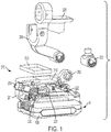
- Fig. 1 illustrates components of the base 200.
- Fig. 1 is a partially exploded view and one half of a housing 201 of the common base 200 is removed to illustrate internals.
- the common base 200 comprises a housing 201.
- the housing 201 is removably attachable to the power tool battery pack 100.
- the actuator 205 may be used to turn on or off one of the variety of tools.
- the actuator 205 may be used to turn on or off the rotary tool 400, lamp light 700, fan 800, etc.
- the actuator 205 is a rotatable knob, but other actuators are possible.
- the actuator 205 may provide a variable input.
- the knob may be used to control the fan 800 rotation or rotary tool 400 rotation at different speeds.
- the knob may control the intensity of the light for the lamp light 700.
- the actuator 205 could simply turn a tool on and off. Additionally, the actuator 205 may in some tools serve only as an on and off actuator and in other tools provide different settings, such as different speed or intensity settings.
- the housing 201 also houses a circuit board 220 including a controller 221.
- the controller 221 can provide a proportional 100W (watts) PWM (pulse-width-modulation) power delivery system that allows for the setting of speed, temperature control, lighting control or fan speed, depending upon the particular tool.
- the proportional pulse-width-modulation power delivery may be in the range of 80W to 120W.
- pulse-width-modulation power delivery may be in the range of 50W to 150W.
- the circuit board 220 may be a printed circuit board.
- the controller 221 may include a microprocessor. There may be a memory 222 on the circuit board 220 and the controller 221 may itself have a memory component.
- circuit board 220 Other components may also be mounted on the circuit board 220 such as sensors, resistors or charge and discharge controls.
- the circuit board 220, controller 221, memory 222 and the provided pulse-width-modulation power delivery may be the same for each of the tools. That allows the same design to be used for a variety of different tools 400, 500, 600, 700, 800.
- Each of the tools 400, 500, 600, 700, 800 has a base that is similar to the common base 200.
- the housing 201 includes a recess 210. When used for some tools, the recess can hold a stamped aluminum tray 250 for holding a solder sponge or other component. Additionally, the housing 201 has a pivot projection 202 which allows pivoting attachment to various tools. The pivot projection 202 attaches to tool arm rest 300. The tool arm rest 300 may be used to hold a variety of different tools. In other embodiments, the pivot projection 202 may attach to an alternate tool holder 350. In other embodiments there are additional tool specific features, such as a tool rest 320.
- the battery pack 100 serves as a weighted base for each of the tools 400, 500, 600, 700, 800.
- the battery pack 100 may be placed on a stable surface, such as a flat horizontal surface made by a table or floor and remain in place.
- the tools 400, 500, 600, 700, 800 each have working portions which can be remote from the battery pack 100 and the respective bases and base housings.
- the working portions of the tools may be connected to the base, base housings and battery packs 100 by a connection section.
- the connection section may in some instances be a cord, as in the rotary tool 400, glue gun 500 and soldering iron 600. In other instances the connection section may be a movable stand, such as with the light 700 and the fan 800.
- the common control hardware and a similar housing can be used to connect to the battery pack 100 serving as a weighted base of the product.
- each tool can perform work away from the base and battery pack 100 owing to the connection section.
- the battery pack 100 is connected to the base 200 in a direction A.
- the PCB 220 is disposed in a plane parallel to the direction A.
- the PCB 220 is also disposed in a plane parallel to a bottom of the battery pack 100 and a central major plane of the battery pack 100.
- Fig. 2 illustrates the rotary tool 400.
- the rotary tool 400 is powered by the removable battery pack 100.
- the rotary tool 400 has a base 450 with a base housing 451.
- the base housing 451 houses the same components as the base housing 201 shown in Fig. 1 .
- the base housing 451 houses a printed circuit board (PCB) 220 on which a controller 221 and a memory 222 are mounted.
- the user operated actuator 455 is connected to the controller 221 through the PCB 220.
- the rotary tool 400 is connected to the base housing 451 by a cord 401 which carries power to the rotary tool 400.
- the cord 401 allows the rotary tool 400 to be used and positioned remote from the base housing 451 and in a variety of orientations.
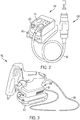
- Fig. 3 illustrates the glue gun 500.
- the glue gun 500 is also powered by the removable battery pack 100.
- the glue gun 500 has a base 550 with a base housing 551.
- the base housing 551 houses the same components as the base housing 201 shown in Fig. 1 .
- the base housing 551 houses a printed circuit board (PCB) 220 on which a controller 221 and a memory 222 are mounted.
- the user operated actuator 555 is connected to the controller 221 through the PCB 220.
- the user operated actuator 555 is on the glue gun housing.
- the glue gun 500 is connected to the base housing 551 by a cord 501 which carries power to the rotary tool 500.
- the cord 501 allows the glue gun 500 to be used and positioned remote from the base housing 551 and in a variety of orientations.
- the glue gun 500 may rest on tool rest 520.
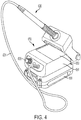
- Fig. 4 illustrates the soldering iron 600.
- the soldering iron 600 is powered by the removable battery pack 100.
- the soldering iron 600 has a base 650 with a base housing 651.
- the base housing 651 houses the same components as the base housing 201 shown in Fig. 1 .
- the base housing 651 houses a printed circuit board (PCB) 220 on which a controller 221 and a memory 222 are mounted.
- the user operated actuator 655 is connected to the controller 221 through the PCB 220. In this case, the user operated actuator 655 controls the temperature of the soldering iron 600.
- the soldering iron 600 is connected to the base housing 651 by a cord 601 which carries power to the soldering iron 600.
- the housing 651 includes a recess for a sponge 653.
- the cord 601 allows the soldering iron 600 to be used and positioned remote from the base housing 651 and in a variety of orientations.
- the soldering iron 600 is shown in Fig. 4 resting in a tool rest 620.
- the tool rest 620 is pivotably attached to the base housing 651.
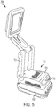
- Fig. 5 illustrates the lamp light 700.
- the lamp light 700 is powered by the removable battery pack 100.
- the lamp light 700 has a base 750 with a base housing 751.
- the base housing 751 houses the same components as the base housing 201 shown in Fig. 1 .
- the base housing 751 houses a printed circuit board (PCB) 220 on which a controller 221 and a memory 222 are mounted.
- the user operated actuator 755 is connected to the controller 221 through the PCB 220.
- the user operated actuator 755 can turn the light on and off and adjust the brightness of the light 700.
- the lamp light 700 includes a collapsible stand 701 for changing the orientation of the light given off by the lamp light 700.
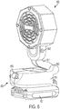
- Fig. 6 illustrates the fan 800.
- the fan 800 is powered by the removable battery pack 100.
- the fan 800 has a base 850 with a base housing 851.
- the base housing 851 houses the same components as the base housing 201 shown in Fig. 1 .
- the base housing 851 houses a printed circuit board (PCB) 220 on which a controller 221 and a memory 222 are mounted.
- the user operated actuator 855 is connected to the controller 221 through the PCB 220.
- the user operated actuator 855 can turn the fan 800 on and off and control the speed of rotation of the fan 800.
- the fan 800 includes a pivoting stand 801 for changing the orientation of the fan 800.
- the pivoting stand 801 includes two pivots 802 and 803.
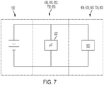
- Fig. 7 is a schematic illustration of the battery pack 100, base 450, 550, 650, 750, 850 and the various tools 400, 500, 600, 700, 800.
- the battery pack 100 is connected to the controller 221.
- the controller 221 provides a PWM power delivery to the tools 400, 500, 600, 700, 800, such as a tool specific component 900.
- the tool specific component 900 varies depending on the particular tool.
- the tool specific component 900 may be a motor in the event of the rotary tool 400 and the fan 800. The motor would be driven to drive the rotary tool 400 or the fan blades of the fan 800.
- the tool specific component 900 may be one or more light-emitting-diodes (LEDs). The LEDs are driven by the power supplied by the controller 221 from the battery pack 100 to produce the light of the lamp light 700.
- the tool specific component 900 may be a heating element such as a resistive heating element. As will be appreciated, the heating element will provide the heat for melting the glue for the glue gun 500 or allowing solering by the soldering iron 600.
- small detail tools may be part of the system.
- small die grinders chisels, polishers and reciprocating knives.
- the removable battery pack 100 is a power tool battery pack. Accordingly, the battery pack 100 may also power other power tools including larger tools such as a drill, impact driver, circular saw, etc. which may not share the common base, electronics and connection section as the embodiments of the present application.
Landscapes
- Engineering & Computer Science (AREA)
- Mechanical Engineering (AREA)
- Chemical & Material Sciences (AREA)
- Chemical Kinetics & Catalysis (AREA)
- Electrochemistry (AREA)
- General Chemical & Material Sciences (AREA)
- Life Sciences & Earth Sciences (AREA)
- Biophysics (AREA)
- Computer Hardware Design (AREA)
- Battery Mounting, Suspending (AREA)
Abstract
A power tool system includes a removable battery pack, a first tool and a second tool. The first tool includes a first base housing that is selectively engageable with the removable battery pack and a first tool portion connected to the first base housing by a first connecting section. The second tool includes a second base housing that is selectively engageable with the removable battery pack and a second tool portion connected to the second base housing by a second connecting section. The second tool base housing houses a second controller that provides a proportional power delivery system for the second tool and second tool base housing also includes a second actuator for providing user control of the second tool.
Description
- The present disclosure relates to a power tool system.
- The present invention provides a power tool system according to claim 1 of the appended claims.
- Preferred, and other optional, features of the invention are described and defined in the dependent claims.
- Aspects of the present disclosure relate to a power tool system, tools for the power tool system and tools having a base, a battery pack and a tool. According to an aspect, there is an exemplary embodiment of a power tool system, the system including a removable battery pack. The system further includes a first tool, the first tool including a first base housing that is selectively engageable with the removable battery pack and a first tool portion connected to the first base housing by a first connecting section. The first tool base housing houses a first controller that provides a proportional power delivery system for the first tool. The first tool base housing further comprises a first actuator for providing user control of the first tool. The system further includes a second tool, the second tool including a second base housing that is selectively engageable with the removable battery pack and a second tool portion connected to the second base housing by a second connecting section. The second tool base housing houses a second controller that provides a proportional power delivery system for the second tool. The second tool base housing further comprises a second actuator for providing user control of the second tool.
- The first tool base housing may further house a first circuit board and the first controller is mounted on the first circuit board.
- The second tool base housing may further house a second circuit board and the second controller is mounted on the second circuit board.
- The battery pack may be inserted into the first tool base housing along a first plane.
- The first circuit board may be disposed in a first circuit board plane which is substantially parallel to the first plane.
- The battery pack may be inserted into the second tool base housing along a second plane.
- The second circuit board may be disposed in a second circuit board plane which is substantially parallel to the second plane.
- The first actuator may have the same configuration as the second actuator.
- The first circuit board may have the same configuration as the second circuit board.
- The first controller may provide the proportional power delivery in the range of 80W to 120W pulse-width-modulation and the second controller provides the proportional power delivery in the range of 80W to 120W pulse-width-modulation.
- The first controller and the second controller may provide the same proportional power delivery.
- The first tool may be a rotary tool and the second tool may be a soldering tool.
- The first connecting section may comprise a cord.
- The battery pack may serve as a weighted base for the first tool.
- According to another aspect, there is a power tool system, the system comprising a removable battery pack and a first tool. The first tool includes a first base housing that is selectively engageable with the removable battery pack and a first tool portion connected to the first base housing by a first cord. The first tool base housing houses a first controller that provides a proportional power delivery system for the first tool. The first tool base housing further comprises a first actuator for providing user control of the first tool. The system further includes a second tool, the second tool including a second base housing that is selectively engageable with the removable battery pack and a second tool portion connected to the second base housing by a second cord. The second tool base housing houses a second controller that provides a proportional power delivery system for the second tool. The second tool base housing further comprises a second actuator for providing user control of the second tool.
- The first tool base housing may further house a first circuit board and the first controller is mounted on the first circuit board.
- The second tool base housing may further house a second circuit board and the second controller may be mounted on the second circuit board.
- The battery pack may be inserted into the first tool base housing along a first direction or plane. The first circuit board may be disposed in a first circuit board plane which is substantially parallel to the first plane.
- The first circuit board may have the same configuration as the second circuit board.
- The first controller may provide the proportional power delivery in the range of 80W to 120W pulse-width-modulation and the second controller provides the proportional power delivery in the range of 80W to 120W pulse-width-modulation.
- The first controller and the second controller may provide the same proportional power delivery.
- The first tool may be a rotary tool and the second tool may be a soldering tool.
- The battery pack may serve as a weighted base for the first tool.
- These and other aspects of various exemplary embodiments of the present invention, as well as the methods of operation and functions of the related elements of structure and the combination of parts and economies of manufacture, will become more apparent upon consideration of the following description and the appended claims with reference to the accompanying drawings, all of which form a part of this specification, wherein like reference numerals designate corresponding parts in the various figures. It is to be expressly understood, however, that the drawings are for the purpose of illustration and description. In addition, it should be appreciated that structural features shown or described in any one embodiment herein can be used in other embodiments as well.
- For a better understanding of exemplary embodiments of the present invention as well as other objects and further features thereof, reference is made to the following description which is to be used in conjunction with the accompanying drawings, where:
-
FIG. 1 is an illustrative view of a battery pack and common base features according to an exemplary embodiment of the present invention; -
FIG. 2 is a perspective view of an exemplary embodiment of a rotary tool; -
FIG. 3 is a perspective view of an exemplary embodiment of a glue gun; -
FIG. 4 is a perspective view of an exemplary embodiment of a soldering iron; -
FIG. 5 is a perspective view of an exemplary embodiment of a lamp light; -
FIG. 6 is a perspective view of an exemplary embodiment of a fan; and -
FIG. 7 is a schematic of a battery pack, base and tool according to an exemplary embodiment of the present invention. -
Figs. 1-7 illustrate an exemplary embodiment of a power tool system. The power tool system includes a variety of tools that utilize acommon battery pack 100. Thebattery pack 100 is a removable power tool battery pack and may be of the type shown in, for example,U.S. Patent No. 7,598,705 ;U.S. Patent No. 7,661,486 ; orU.S. Patent Application Publication No. 2018/0331335 .U.S. Patent No. 7,598,705 ;U.S. Patent No. 7,661,486 ; andU.S. Patent Application Publication No. 2018/0331335 are hereby incorporated by reference. - Each tool in the power tool system of the exemplary embodiment also includes a
common base 200. Each tool then is built incorporating thiscommon base 200. For example, the specific tools may include arotary tool 400, as shown inFig. 2 ; ahot glue gun 500, as shown inFig. 3 ; asoldering iron 600, as shown inFig. 4 ; alamp light 700, as shown inFig. 5 ; or afan 800, as shown inFig. 6 . Each of these tools is also powered by abattery pack 100. -
Fig. 1 illustrates components of thebase 200.Fig. 1 is a partially exploded view and one half of ahousing 201 of thecommon base 200 is removed to illustrate internals. As is shown inFig. 1 , thecommon base 200 comprises ahousing 201. Thehousing 201 is removably attachable to the powertool battery pack 100. There is anactuator 205 on the front of thehousing 201. Theactuator 205 may be used to turn on or off one of the variety of tools. For example, theactuator 205 may be used to turn on or off therotary tool 400,lamp light 700,fan 800, etc. In the exemplary embodiment, theactuator 205 is a rotatable knob, but other actuators are possible. Theactuator 205 may provide a variable input. For example, turning the knob more may increase the speed or intensity of the tool. For example, the knob may be used to control thefan 800 rotation orrotary tool 400 rotation at different speeds. Similarly, the knob may control the intensity of the light for thelamp light 700. In other embodiments theactuator 205 could simply turn a tool on and off. Additionally, theactuator 205 may in some tools serve only as an on and off actuator and in other tools provide different settings, such as different speed or intensity settings. - The
housing 201 also houses acircuit board 220 including acontroller 221. Thecontroller 221 can provide a proportional 100W (watts) PWM (pulse-width-modulation) power delivery system that allows for the setting of speed, temperature control, lighting control or fan speed, depending upon the particular tool. The proportional pulse-width-modulation power delivery may be in the range of 80W to 120W. pulse-width-modulation power delivery may be in the range of 50W to 150W. Thecircuit board 220 may be a printed circuit board. Thecontroller 221 may include a microprocessor. There may be amemory 222 on thecircuit board 220 and thecontroller 221 may itself have a memory component. Other components may also be mounted on thecircuit board 220 such as sensors, resistors or charge and discharge controls. Thecircuit board 220,controller 221,memory 222 and the provided pulse-width-modulation power delivery may be the same for each of the tools. That allows the same design to be used for a variety ofdifferent tools tools common base 200. - As is further shown in
Fig. 1 , thehousing 201 includes arecess 210. When used for some tools, the recess can hold a stampedaluminum tray 250 for holding a solder sponge or other component. Additionally, thehousing 201 has apivot projection 202 which allows pivoting attachment to various tools. Thepivot projection 202 attaches totool arm rest 300. Thetool arm rest 300 may be used to hold a variety of different tools. In other embodiments, thepivot projection 202 may attach to analternate tool holder 350. In other embodiments there are additional tool specific features, such as atool rest 320. - As shown in
Figs. 2-6 , thebattery pack 100 serves as a weighted base for each of thetools battery pack 100 may be placed on a stable surface, such as a flat horizontal surface made by a table or floor and remain in place. Thetools battery pack 100 and the respective bases and base housings. The working portions of the tools may be connected to the base, base housings and battery packs 100 by a connection section. The connection section may in some instances be a cord, as in therotary tool 400,glue gun 500 andsoldering iron 600. In other instances the connection section may be a movable stand, such as with the light 700 and thefan 800. In each instance, the common control hardware and a similar housing can be used to connect to thebattery pack 100 serving as a weighted base of the product. At the same time, each tool can perform work away from the base andbattery pack 100 owing to the connection section. - As is shown in
Fig. 1 , thebattery pack 100 is connected to the base 200 in a direction A. ThePCB 220 is disposed in a plane parallel to the direction A. ThePCB 220 is also disposed in a plane parallel to a bottom of thebattery pack 100 and a central major plane of thebattery pack 100. -
Fig. 2 illustrates therotary tool 400. Therotary tool 400 is powered by theremovable battery pack 100. Therotary tool 400 has a base 450 with abase housing 451. Thebase housing 451 houses the same components as thebase housing 201 shown inFig. 1 . In particular, thebase housing 451 houses a printed circuit board (PCB) 220 on which acontroller 221 and amemory 222 are mounted. The user operatedactuator 455 is connected to thecontroller 221 through thePCB 220. As shown inFig. 2 , therotary tool 400 is connected to thebase housing 451 by acord 401 which carries power to therotary tool 400. Thecord 401 allows therotary tool 400 to be used and positioned remote from thebase housing 451 and in a variety of orientations. -
Fig. 3 illustrates theglue gun 500. Theglue gun 500 is also powered by theremovable battery pack 100. Theglue gun 500 has a base 550 with abase housing 551. Thebase housing 551 houses the same components as thebase housing 201 shown inFig. 1 . In particular, thebase housing 551 houses a printed circuit board (PCB) 220 on which acontroller 221 and amemory 222 are mounted. The user operatedactuator 555 is connected to thecontroller 221 through thePCB 220. In this case, the user operatedactuator 555 is on the glue gun housing. As shown inFig. 3 , theglue gun 500 is connected to thebase housing 551 by acord 501 which carries power to therotary tool 500. Thecord 501 allows theglue gun 500 to be used and positioned remote from thebase housing 551 and in a variety of orientations. Theglue gun 500 may rest on tool rest 520. -
Fig. 4 illustrates thesoldering iron 600. Thesoldering iron 600 is powered by theremovable battery pack 100. Thesoldering iron 600 has a base 650 with abase housing 651. Thebase housing 651 houses the same components as thebase housing 201 shown inFig. 1 . In particular, thebase housing 651 houses a printed circuit board (PCB) 220 on which acontroller 221 and amemory 222 are mounted. The user operatedactuator 655 is connected to thecontroller 221 through thePCB 220. In this case, the user operatedactuator 655 controls the temperature of thesoldering iron 600. As shown inFig. 4 , thesoldering iron 600 is connected to thebase housing 651 by acord 601 which carries power to thesoldering iron 600. Thehousing 651 includes a recess for asponge 653. Thecord 601 allows thesoldering iron 600 to be used and positioned remote from thebase housing 651 and in a variety of orientations. Thesoldering iron 600 is shown inFig. 4 resting in a tool rest 620. The tool rest 620 is pivotably attached to thebase housing 651. -
Fig. 5 illustrates thelamp light 700. Thelamp light 700 is powered by theremovable battery pack 100. Thelamp light 700 has a base 750 with abase housing 751. Thebase housing 751 houses the same components as thebase housing 201 shown inFig. 1 . In particular, thebase housing 751 houses a printed circuit board (PCB) 220 on which acontroller 221 and amemory 222 are mounted. The user operatedactuator 755 is connected to thecontroller 221 through thePCB 220. The user operatedactuator 755 can turn the light on and off and adjust the brightness of the light 700. As shown inFig. 5 , thelamp light 700 includes acollapsible stand 701 for changing the orientation of the light given off by thelamp light 700. -
Fig. 6 illustrates thefan 800. Thefan 800 is powered by theremovable battery pack 100. Thefan 800 has a base 850 with abase housing 851. Thebase housing 851 houses the same components as thebase housing 201 shown inFig. 1 . In particular, thebase housing 851 houses a printed circuit board (PCB) 220 on which acontroller 221 and amemory 222 are mounted. The user operatedactuator 855 is connected to thecontroller 221 through thePCB 220. The user operatedactuator 855 can turn thefan 800 on and off and control the speed of rotation of thefan 800. As shown inFig. 6 , thefan 800 includes a pivotingstand 801 for changing the orientation of thefan 800. The pivotingstand 801 includes twopivots 802 and 803. -
Fig. 7 is a schematic illustration of thebattery pack 100,base various tools battery pack 100 is connected to thecontroller 221. As discussed above, thecontroller 221 provides a PWM power delivery to thetools specific component 900. The toolspecific component 900 varies depending on the particular tool. For example, the toolspecific component 900 may be a motor in the event of therotary tool 400 and thefan 800. The motor would be driven to drive therotary tool 400 or the fan blades of thefan 800. In the case of thelamp light 700, the toolspecific component 900 may be one or more light-emitting-diodes (LEDs). The LEDs are driven by the power supplied by thecontroller 221 from thebattery pack 100 to produce the light of thelamp light 700. For theglue gun 500 and thesoldering iron 600, the toolspecific component 900 may be a heating element such as a resistive heating element. As will be appreciated, the heating element will provide the heat for melting the glue for theglue gun 500 or allowing solering by thesoldering iron 600. - In addition to the tools shown in
Figs. 2-6 , other small detail tools may be part of the system. For example, small die grinders, chisels, polishers and reciprocating knives. - As will be appreciated, the
removable battery pack 100 is a power tool battery pack. Accordingly, thebattery pack 100 may also power other power tools including larger tools such as a drill, impact driver, circular saw, etc. which may not share the common base, electronics and connection section as the embodiments of the present application. - Although the present technology has been described in detail for the purpose of illustration based on what is currently considered to be the most practical and preferred embodiments, it is to be understood that such detail is solely for that purpose and that the technology is not limited to the disclosed embodiments, but, on the contrary, is intended to cover modifications and equivalent arrangements that are within the scope of the appended claims. For example, it is to be understood that the present technology contemplates that, to the extent possible, one or more features of any embodiment can be combined with one or more features of any other embodiment.
- Additionally, while the exemplary embodiment is described with respect to an oscillating tool, the methods and configurations may also apply to or encompass other power tools such as other tools holding accessories.
Claims (14)
- A power tool system, the system comprising:a removable battery pack;a first tool, the first tool including a first base housing that is selectively engageable with the removable battery pack and a first tool portion connected to the first base housing by a first connecting section;wherein the first tool base housing houses a first controller that provides a proportional power delivery system for the first tool;wherein the first tool base housing further comprises a first actuator for providing user control of the first tool;a second tool, the second tool including a second base housing that is selectively engageable with the removable battery pack and a second tool portion connected to the second base housing by a second connecting section;wherein the second tool base housing houses a second controller that provides a proportional power delivery system for the second tool; andwherein the second tool base housing further comprises a second actuator for providing user control of the second tool.
- The power tool system of claim 1, wherein the first tool base housing further houses a first circuit board and the first controller is mounted on the first circuit board.
- The power tool system of claim 1 or claim 2, wherein the second tool base housing further houses a second circuit board and the second controller is mounted on the second circuit board.
- The power tool system of claim 2, or claim 3 when dependent upon claim 2, wherein the battery pack is inserted into the first tool base housing along a first plane; and
wherein the first circuit board is disposed in a first circuit board plane which is substantially parallel to the first plane. - The power tool system of claim 3 or claim 4, wherein the battery pack is inserted into the second tool base housing along a second plane; and
wherein the second circuit board is disposed in a second circuit board plane which is substantially parallel to the second plane. - The power tool system of any preceding claim, wherein the first actuator has the same configuration as the second actuator.
- The power tool system of claim 3 when dependent upon claim 2, wherein the first circuit board has the same configuration as the second circuit board.
- The power tool system of any preceding claim, wherein the first controller provides the proportional power delivery in the range of 80W to 120W pulse-width-modulation and the second controller provides the proportional power delivery in the range of 80W to 120W pulse-width-modulation.
- The power tool system of any preceding claim, wherein the first controller and the second controller provide the same proportional power delivery.
- The power tool system of any preceding claim, wherein the first tool is a rotary tool and/or the second tool is a soldering tool.
- The power tool system of any preceding claim, wherein the first connecting section and/or the second connecting section comprises a flexible cord.
- The power tool system of any preceding claim, wherein the battery pack serves as a weighted base for the first tool and/or the second tool.
- The power tool system of any preceding claim, wherein the first connecting section and/or the second connecting section comprises a substantially rigid arm or a substantially rigid stand.
- The power tool system of claim 13, wherein the arm or stand is collapsible and/or jointed.
Applications Claiming Priority (1)
| Application Number | Priority Date | Filing Date | Title |
|---|---|---|---|
| US201962884309P | 2019-08-08 | 2019-08-08 |
Publications (1)
| Publication Number | Publication Date |
|---|---|
| EP3772392A1 true EP3772392A1 (en) | 2021-02-10 |
Family
ID=71994383
Family Applications (1)
| Application Number | Title | Priority Date | Filing Date |
|---|---|---|---|
| EP20189850.9A Withdrawn EP3772392A1 (en) | 2019-08-08 | 2020-08-06 | Power tool system |
Country Status (2)
| Country | Link |
|---|---|
| US (6) | US11858106B2 (en) |
| EP (1) | EP3772392A1 (en) |
Cited By (1)
| Publication number | Priority date | Publication date | Assignee | Title |
|---|---|---|---|---|
| US12128537B2 (en) | 2020-05-18 | 2024-10-29 | Techtronic Cordless Gp | Rotary tool |
Families Citing this family (1)
| Publication number | Priority date | Publication date | Assignee | Title |
|---|---|---|---|---|
| WO2021115484A1 (en) | 2019-12-13 | 2021-06-17 | 苏州宝时得电动工具有限公司 | Control device and electric power tool system |
Citations (5)
| Publication number | Priority date | Publication date | Assignee | Title |
|---|---|---|---|---|
| US20050267776A1 (en) * | 2003-08-22 | 2005-12-01 | Selby David A | Combo kit and method of providing a combo kit |
| WO2013137480A2 (en) * | 2012-03-14 | 2013-09-19 | Hitachi Koki Co., Ltd. | Electric tool |
| US20160099575A1 (en) * | 2014-10-06 | 2016-04-07 | Black & Decker Inc. | Portable Power Supply |
| US20180076653A1 (en) * | 2014-05-18 | 2018-03-15 | Black & Decker, Inc. | Power tool having a universal motor capable of being powered by ac or dc power supply |
| EP3450112A1 (en) * | 2017-08-28 | 2019-03-06 | TTI (Macao Commercial Offshore) Limited | Electric tool system and method of operating the same |
Family Cites Families (221)
| Publication number | Priority date | Publication date | Assignee | Title |
|---|---|---|---|---|
| US568539A (en) | 1896-09-29 | Office | ||
| US762650A (en) | 1903-10-19 | 1904-06-14 | Joseph F Eaton | Drill-chuck. |
| US1470197A (en) | 1922-02-18 | 1923-10-09 | Millers Falls Co | Chuck |
| US2056951A (en) | 1933-09-05 | 1936-10-13 | Earl B Smith | Electric soldering iron |
| US2040517A (en) | 1934-10-22 | 1936-05-12 | Brown Mclaren Mfg Company | Chuck mechanism |
| US2413422A (en) | 1944-06-20 | 1946-12-31 | Black & Decker Mfg Co | Chuck |
| US2591287A (en) | 1949-06-04 | 1952-04-01 | Revere Camera Co | Chuck |
| US2682413A (en) | 1952-06-12 | 1954-06-29 | Guy H Tripp | Chuck |
| US2777703A (en) | 1955-01-25 | 1957-01-15 | Harold D Pickett | Cam actuated collet |
| US3247360A (en) | 1963-01-18 | 1966-04-19 | Charles L Ponder | Electrically heated nursing bottles |
| US3287541A (en) | 1964-07-13 | 1966-11-22 | Weller Electric Corp | Temperature controlled soldering iron |
| DE1282810B (en) | 1965-01-13 | 1968-11-14 | Ersa Ernst Sachs K G | Electric soldering iron |
| US3430816A (en) | 1967-08-17 | 1969-03-04 | Daubert Chem Co | Apparatus for dispensing adhesive materials |
| DE1928955A1 (en) | 1969-06-07 | 1970-12-10 | Bosch Gmbh Robert | Drill chuck |
| CH516368A (en) | 1969-06-11 | 1971-12-15 | Sachs Ersa Kg | Electric soldering iron |
| US3706871A (en) | 1970-05-08 | 1972-12-19 | William W Witherow | Self-supported soldering device |
| US4050003A (en) | 1974-08-23 | 1977-09-20 | The Black And Decker Manufacturing Company | Modular cordless tools |
| US3984655A (en) | 1975-05-19 | 1976-10-05 | Wahl Clipper Corporation | Terminal members of an electric tool for receiving detachable tips |
| US4084123A (en) | 1975-08-25 | 1978-04-11 | Disston, Inc. | Cordless electric devices having rechargeable battery pack(s) |
| US4117854A (en) | 1977-02-10 | 1978-10-03 | Rosenbloom William J | Electric manicure |
| JPS5761480A (en) * | 1980-09-26 | 1982-04-13 | Hitachi Koki Kk | Motor tool |
| US4505170A (en) | 1982-09-30 | 1985-03-19 | Laere Christiaan G M | Hand-holdable electric power tool apparatus |
| US4619162A (en) | 1982-09-30 | 1986-10-28 | Laere Christiaan G M | Hand-holdable electric power tool apparatus |
| US4905423A (en) | 1982-09-30 | 1990-03-06 | Laere Christiaan G M | Electric rotary power tool apparatus holdable by hand during operation, kit comprising the same, and novel switch means therefor |
| US4671476A (en) | 1986-01-10 | 1987-06-09 | Euisub Yim | Adjustable soldering iron stand |
| GB2191396A (en) | 1986-06-10 | 1987-12-16 | Lamberto De Santis | A portable powered device for the care of finger nails |
| USD304368S (en) | 1986-11-11 | 1989-10-31 | Sharp Kabushiki Kaisha | Electric fan |
| US4826049A (en) | 1987-08-07 | 1989-05-02 | Black & Decker Inc. | Cordless adhesive dispensing system |
| USD308932S (en) | 1987-08-07 | 1990-07-03 | Black & Decker Inc. | Base for a glue gun or similar article |
| US5144217A (en) * | 1989-03-03 | 1992-09-01 | Black & Decker Inc. | Cordless tool battery housing and charging system |
| US4883942A (en) | 1988-03-21 | 1989-11-28 | Robatherm Products | Low voltage heating element for portable tools |
| WO1989010324A1 (en) | 1988-04-25 | 1989-11-02 | Swingline Inc. | Portable electrically heated appliance employing fusible heat storage material |
| CN2042568U (en) | 1988-06-14 | 1989-08-09 | 宋惠东 | Multi-functional power saving separable combined fan and desk lamp |
| IL93142A (en) | 1990-01-23 | 1994-04-12 | Davidovitz Zvi | Electric fingernail clipper |
| US4998589A (en) | 1990-02-26 | 1991-03-12 | Wiesendanger John A | Variable speed drill control cam apparatus |
| EP0526386A1 (en) | 1991-07-25 | 1993-02-03 | Zvi Davidovitz | Cutter device particularly useful for cutting fingernails or toenails |
| JP3221703B2 (en) | 1991-11-01 | 2001-10-22 | 松下電器産業株式会社 | Component allocation method and device |
| US5495093A (en) | 1993-02-05 | 1996-02-27 | Edsyn, Inc. | Soldering apparatus processor having temperature selection, calibration and heating control of tip |
| US5446262A (en) | 1994-04-19 | 1995-08-29 | Wahl Clipper Corporation | Soldering iron and soldering iron tip with spaced heatable shell member |
| US6463361B1 (en) | 1994-09-22 | 2002-10-08 | Computer Motion, Inc. | Speech interface for an automated endoscopic system |
| DE29508404U1 (en) | 1995-05-20 | 1995-08-17 | Promed GmbH, 82490 Farchant | Cosmetic treatment device, in particular nail care device |
| US5780819A (en) | 1995-07-07 | 1998-07-14 | Fabrikant; Marvin | Heater for shaving cream containers with dome-shaped support and heating surface |
| WO1997003539A1 (en) | 1995-07-07 | 1997-01-30 | Marvin Fabrikant | Heater for a liquid or gel container |
| FR2739266B1 (en) | 1995-10-03 | 1997-12-19 | Seb Sa | APPLICATOR AND APPLICATOR ASSEMBLY OF THERMAL MELT |
| JP3216040B2 (en) | 1995-11-02 | 2001-10-09 | 株式会社フジクラ | Batch connection device |
| DE29600771U1 (en) | 1996-01-17 | 1997-05-28 | Cooper Industries, Inc., Houston, Tex. | soldering iron |
| US5865499A (en) * | 1996-04-01 | 1999-02-02 | Keyser; Norbert R. | Camper crank |
| US5871272A (en) | 1997-01-28 | 1999-02-16 | Streamlight, Incorporated | Flashlight with rotatable lamp head |
| AU7144798A (en) | 1997-05-16 | 1998-12-08 | Bausch & Lomb Incorporated | Adjustable magnifying apparatus and method for viewing video or computer screens |
| GB2327054A (en) | 1997-07-08 | 1999-01-13 | Black & Decker Inc | Shaft locking |
| US6007373A (en) | 1998-05-22 | 1999-12-28 | Chew; William E. | Apparatuses and methods for coupling DC power tools to external DC power sources |
| DE50001168D1 (en) | 1999-03-05 | 2003-03-06 | Steinel Gmbh & Co Kg | HEIZKLEBEVORRICHTUNG |
| FR2794931B1 (en) * | 1999-06-18 | 2001-09-07 | Noel Gabard | DEVICE AND METHOD FOR TREATING SOILS BY AERATION WITH WASTE STORAGE |
| US6260985B1 (en) | 1999-07-23 | 2001-07-17 | Noel E. Zeller | Multipurpose portable electric lighting apparatus |
| US6797924B1 (en) | 1999-08-18 | 2004-09-28 | Dragos Axinte | Cordless soldering iron and electrical continuity testing device |
| US20050247692A1 (en) | 1999-08-18 | 2005-11-10 | Grigore Axinte | Cordless soldering tool |
| US6646228B2 (en) | 1999-08-18 | 2003-11-11 | Hyperion Innovations, Inc. | Cordless soldering iron |
| JP2001062724A (en) | 1999-08-26 | 2001-03-13 | Matsushita Electric Works Ltd | Keratin grinding implement |
| DE19945551C2 (en) | 1999-09-23 | 2002-08-08 | Robert Schroeder Gmbh & Co Kg | Miniature drill |
| US6286609B1 (en) * | 1999-12-10 | 2001-09-11 | Black & Decker Inc. | AC/DC chopper for power tool |
| JP2001258634A (en) | 2000-03-21 | 2001-09-25 | Katsumi Ohiro | Electric grinder for nails |
| JP2001300867A (en) | 2000-04-21 | 2001-10-30 | Makita Corp | Adapter for power tool |
| US20020134811A1 (en) * | 2001-01-29 | 2002-09-26 | Senco Products, Inc. | Multi-mode power tool utilizing attachment |
| DE10112129A1 (en) | 2001-03-14 | 2002-09-19 | Hilti Ag | Intake module |
| US6729413B2 (en) | 2001-08-24 | 2004-05-04 | Black & Decker Inc. | Power tool with battery pack ejector |
| US6902293B2 (en) * | 2001-11-19 | 2005-06-07 | Techtronic Industrial Co., Ltd. | Battery-operated lighting device |
| JP2003211374A (en) | 2002-01-21 | 2003-07-29 | Hitachi Koki Co Ltd | Electric tool |
| US6820768B2 (en) | 2002-01-25 | 2004-11-23 | Adhesive Technologies, Inc. | Elongate hand held glue gun |
| US6575590B1 (en) | 2002-03-01 | 2003-06-10 | Jake Wadsworth | Light system for battery powered drill |
| US7296323B2 (en) * | 2002-08-21 | 2007-11-20 | Hitachi Koki Co., Ltd. | Dust collector |
| US7578598B2 (en) | 2006-11-13 | 2009-08-25 | Black & Decker Inc. | Battery charging work light |
| US7357526B2 (en) | 2003-08-22 | 2008-04-15 | Milwaukee Electric Tool Corporation | Power tool and accessory |
| US7131364B2 (en) * | 2003-08-25 | 2006-11-07 | Eastway Fair Company, Ltd. | Collapsible stand for a bench-top power tool |
| DE10348693B4 (en) | 2003-10-16 | 2009-06-04 | Hilti Aktiengesellschaft | Electrical connection device for hand tool accessories |
| US6942229B2 (en) * | 2003-10-31 | 2005-09-13 | One World Technologies Limited | Collapsible stand for a bench-top power tool |
| US7942617B2 (en) | 2004-01-14 | 2011-05-17 | Robert Bosch Tool Corporation | Nose tip control for cordless high speed rotary tool |
| WO2005087449A1 (en) | 2004-03-15 | 2005-09-22 | Maxtech Manufacturing Inc. | Rotary tool with improved connecting means for attachments thereto |
| US7975893B2 (en) | 2004-04-02 | 2011-07-12 | Black & Decker Inc. | Return cord assembly for a power tool |
| EP2174750B1 (en) * | 2004-04-13 | 2012-03-28 | Black & Decker Inc. | Electric sander and motor control therefor |
| DE202004008391U1 (en) | 2004-05-26 | 2005-10-06 | Cooper Tools Gmbh | soldering iron |
| WO2006002384A1 (en) | 2004-06-24 | 2006-01-05 | Select-Measure Consumption, L.L.C. | Metered volume liquid dispensing device |
| US7557536B2 (en) | 2004-11-07 | 2009-07-07 | Milwaukee Electric Tool Corporation | Light |
| JP4429879B2 (en) | 2004-11-25 | 2010-03-10 | 太洋電機産業株式会社 | Soldering iron and soldering iron manufacturing method |
| US20060150992A1 (en) | 2005-01-07 | 2006-07-13 | Nevakshonoff Michael G | Device for sanding buffing or grinding elongate objects |
| US7222986B2 (en) | 2005-03-07 | 2007-05-29 | Daka Research Inc. | Multiple swivel flashlight |
| US7621652B2 (en) | 2005-03-31 | 2009-11-24 | Milwaukee Electric Tool Corporation | Electrical component, such as a lighting unit and battery charger assembly |
| USD536718S1 (en) | 2005-08-04 | 2007-02-13 | Eric Murray | Cordless soldering apparatus |
| EP1928626A4 (en) | 2005-08-29 | 2009-01-07 | Demain Technology Pty Ltd | Power tool |
| US7551411B2 (en) | 2005-10-12 | 2009-06-23 | Black & Decker Inc. | Control and protection methodologies for a motor control module |
| US8657031B2 (en) | 2005-10-12 | 2014-02-25 | Black & Decker Inc. | Universal control module |
| US7446493B2 (en) | 2005-10-12 | 2008-11-04 | Black & Decker Inc. | Control methodologies for a motor control module |
| US7428881B2 (en) | 2005-10-25 | 2008-09-30 | Jay Drelinger | Rotary nail filing apparatus for animals |
| EP1780865B1 (en) | 2005-10-31 | 2017-02-22 | Black & Decker, Inc. | Thermal management system for a battery pack |
| US7497275B2 (en) | 2005-11-04 | 2009-03-03 | Black & Decker Inc. | Cordless power tool system with improved power output |
| US20070186867A1 (en) | 2006-02-13 | 2007-08-16 | Greg Mulloy | Portable handheld animal groomer |
| US20070227310A1 (en) | 2006-03-31 | 2007-10-04 | Heiko Roehm | Hand power tool |
| JP2009535007A (en) | 2006-04-26 | 2009-09-24 | ディメイン テクノロジー プロプライエタリー リミテッド | Charger and rechargeable electrical device |
| US7629766B2 (en) * | 2006-07-17 | 2009-12-08 | Bbs Licensing, Inc. | Adapter system for battery-powered tools |
| US20080069694A1 (en) | 2006-09-19 | 2008-03-20 | Hector Ray Hernandez | Electric fan |
| CN200984676Y (en) | 2006-12-13 | 2007-12-05 | 谭达远 | Electric iron capable of lighting |
| US20080179309A1 (en) | 2007-01-25 | 2008-07-31 | Markovsky Robert T | Soldering Iron with Direct Current Powered Heating Element |
| US20080277546A1 (en) | 2007-05-10 | 2008-11-13 | Peter Kahn | Coupling system |
| US20080302226A1 (en) * | 2007-06-07 | 2008-12-11 | Credo Technology Corporation | Power tool having imaging device and display device |
| US20080305387A1 (en) | 2007-06-11 | 2008-12-11 | Black & Decker Inc. | Cordless power tool system |
| TWI383174B (en) | 2007-07-04 | 2013-01-21 | Univ Far East | Separable magnifying glass lamp |
| TWM330892U (en) * | 2007-09-11 | 2008-04-21 | Mobiletron Electronics Co Ltd | Electric tool |
| GB0801302D0 (en) | 2008-01-24 | 2008-03-05 | Black & Decker Inc | Handle assembly for power tool |
| JP5323364B2 (en) | 2008-02-15 | 2013-10-23 | 株式会社マキタ | Electric tool |
| US8222868B2 (en) | 2008-04-02 | 2012-07-17 | Techtronic Power Tools Technology Limited | Battery tester for rechargeable power tool batteries |
| WO2010008855A1 (en) * | 2008-06-23 | 2010-01-21 | Milwaukee Electric Tool Corporation | Electrical component including a battery charger assembly |
| USD600413S1 (en) | 2008-07-10 | 2009-09-15 | Telebrands Corp. | Pet nail filer |
| USD596357S1 (en) | 2008-11-24 | 2009-07-14 | Rosen Leon D | Pet nail grooming tool |
| ES1070991Y (en) | 2009-07-07 | 2010-03-01 | Ceras Especiales Martinez De S | FUNDABLE PRODUCT APPLICATOR DEVICE |
| US8606540B2 (en) | 2009-11-10 | 2013-12-10 | Projectionworks, Inc. | Hole measurement apparatuses |
| CN201572729U (en) | 2009-12-21 | 2010-09-08 | 马国强 | Molten glue gun capable of cordless operation |
| US8708346B2 (en) | 2010-01-08 | 2014-04-29 | Techtronic Power Tools Technology Limited | Rotary tool including a collet |
| JP5461221B2 (en) | 2010-02-12 | 2014-04-02 | 株式会社マキタ | Electric tool powered by multiple battery packs |
| US8882378B2 (en) | 2010-02-15 | 2014-11-11 | Access Business Group International Llc | Heating and dispenser system |
| US8636081B2 (en) * | 2011-12-15 | 2014-01-28 | Milwaukee Electric Tool Corporation | Rotary hammer |
| US20110226270A1 (en) | 2010-03-12 | 2011-09-22 | Raul Rivera | Personal nail trimmer |
| KR101194121B1 (en) | 2010-03-16 | 2012-10-24 | 황원우 | Cosmetic Cases equipped with heating means |
| US9722334B2 (en) * | 2010-04-07 | 2017-08-01 | Black & Decker Inc. | Power tool with light unit |
| JP2011233409A (en) | 2010-04-28 | 2011-11-17 | Makita Corp | Electrical appliance system |
| JP2011233410A (en) | 2010-04-28 | 2011-11-17 | Makita Corp | Electric equipment system and adapter used for the same |
| US8890468B2 (en) * | 2010-05-14 | 2014-11-18 | Donald L. Bauer | Portable power supply |
| DE102010031162A1 (en) | 2010-07-09 | 2012-01-12 | Robert Bosch Gmbh | Hand luminous device |
| JP5525358B2 (en) * | 2010-07-16 | 2014-06-18 | 株式会社マキタ | Power tool powered by battery pack and its adapter |
| US8894377B2 (en) | 2010-10-06 | 2014-11-25 | Jeffrey Alan Greenberg | Folding personal fan |
| US9878432B2 (en) * | 2010-11-04 | 2018-01-30 | Ingersoll-Rand Company | Cordless power tools with a universal controller and tool and battery identification |
| DE102010062008A1 (en) | 2010-11-26 | 2012-05-31 | Robert Bosch Gmbh | Adhesive agent separating device for use in e.g. pneumatic glue gun, has separation unit i.e. compressed air separation unit, provided for separating material strand after application process using energy flow separating agent |
| RU2013151797A (en) | 2011-04-21 | 2015-05-27 | Инфьюжн Брэндс, Инк. | MULTI-FUNCTIONAL SAW OF BIDIRECTIONAL VIBRATION ACTION |
| JP5367766B2 (en) | 2011-04-22 | 2013-12-11 | 株式会社マキタ | Fan |
| EP3090838B1 (en) * | 2011-05-19 | 2020-06-17 | Black & Decker Inc. | Power tool with force sensing electronic clutch |
| US20140069672A1 (en) | 2011-05-20 | 2014-03-13 | Hitachi Koki Co., Ltd. | Power Tool |
| DE102011077442B4 (en) | 2011-06-14 | 2025-06-26 | Robert Bosch Gmbh | Gearless hand tool |
| DE102011077443A1 (en) | 2011-06-14 | 2012-12-20 | Robert Bosch Gmbh | Hand tool |
| DE102011077440A1 (en) | 2011-06-14 | 2012-12-20 | Robert Bosch Gmbh | Hand tool |
| WO2013014878A1 (en) | 2011-07-24 | 2013-01-31 | Makita Corporation | Battery pack system and method for recharging a battery pack |
| EP2735078B1 (en) | 2011-07-24 | 2017-10-04 | Makita Corporation | Power tool system and adapter therefor |
| DE102012200913A1 (en) | 2012-01-23 | 2013-07-25 | Robert Bosch Gmbh | Electric tool i.e. hot adhesive pistol, for processing e.g. hot-melt adhesive for battery operation to melt heat pipes, has actuating device actuated for producing discharge volume of medium, and cleaning device cleaning adhesive surface |
| US8991806B2 (en) * | 2012-04-19 | 2015-03-31 | John Matthew Meyer | Extension table assembly for power tools |
| JP6124046B2 (en) * | 2012-07-06 | 2017-05-10 | 日立工機株式会社 | Back load type power supply |
| DE202012007997U1 (en) | 2012-08-21 | 2013-12-04 | Apex Brands, Inc. | Hand tool, in particular soldering iron |
| JP5319004B1 (en) | 2012-09-25 | 2013-10-16 | 株式会社エンジニア | Magnifier with stand |
| US10821591B2 (en) * | 2012-11-13 | 2020-11-03 | Milwaukee Electric Tool Corporation | High-power cordless, hand-held power tool including a brushless direct current motor |
| US9539722B2 (en) | 2012-12-19 | 2017-01-10 | Milwaukee Electric Tool Corporation | Tool storage devices |
| GB2509111B (en) | 2012-12-20 | 2017-08-09 | Dyson Technology Ltd | A fan |
| DE102013200576A1 (en) * | 2013-01-16 | 2014-07-17 | Robert Bosch Gmbh | Hand tool with an ergonomic handle |
| JP6048192B2 (en) | 2013-02-13 | 2016-12-21 | 日立工機株式会社 | Electrical equipment and electrical equipment |
| US9620989B2 (en) | 2013-03-13 | 2017-04-11 | Blackbird Tech Llc | Rechargeable battery accessories |
| CN103222724B (en) | 2013-04-22 | 2015-07-08 | 上海奈乐电器科技有限公司 | Automatic safe manicuring knife |
| US9956677B2 (en) * | 2013-05-08 | 2018-05-01 | Black & Decker Inc. | Power tool with interchangeable power heads |
| DE202014102422U1 (en) | 2013-05-31 | 2014-08-08 | Hitachi Koki Co., Ltd. | Electric power tools |
| TWI542789B (en) | 2013-07-17 | 2016-07-21 | 建準電機工業股份有限公司 | Series-connected fan |
| US9762153B2 (en) | 2013-10-18 | 2017-09-12 | Black & Decker Inc. | Cycle-by-cycle current limit for power tools having a brushless motor |
| WO2015061370A1 (en) | 2013-10-21 | 2015-04-30 | Milwaukee Electric Tool Corporation | Adapter for power tool devices |
| JP2015096282A (en) | 2013-11-15 | 2015-05-21 | 日立工機株式会社 | Working equipment |
| US9491997B2 (en) | 2013-12-02 | 2016-11-15 | Soft Lines International, Ltd. | Drum assembly, cosmetic device with drum assembly, and battery compartment for cosmetic device |
| DE202014001956U1 (en) | 2014-02-28 | 2015-05-29 | Weller Tools Gmbh | Lötspitzenbefestigungssystem |
| US9267698B2 (en) | 2014-02-28 | 2016-02-23 | Techtronic Power Tools Technology Limited | Mister fan |
| GB201403971D0 (en) | 2014-03-06 | 2014-04-23 | 7Rdd Ltd | Portable power supply improvements |
| US9743929B2 (en) * | 2014-03-26 | 2017-08-29 | Ethicon Llc | Modular powered surgical instrument with detachable shaft assemblies |
| US20150306674A1 (en) | 2014-04-25 | 2015-10-29 | We Cheer Industrial Co., Ltd. | Structure-improved clamping chuck |
| US10625909B2 (en) | 2014-06-07 | 2020-04-21 | Insurgical, Inc. | Sterile ready-to-use surgical tool having wireless charging system capability |
| DE102014211046A1 (en) | 2014-06-10 | 2015-12-17 | Robert Bosch Gmbh | System comprising at least one electronically commutated electric motor of a defined size and a rechargeable battery of at least one voltage class |
| JP6577229B2 (en) | 2015-02-13 | 2019-09-18 | 株式会社マキタ | Battery pack and battery system |
| KR20160116140A (en) | 2015-03-26 | 2016-10-07 | 계양전기 주식회사 | Connecting apparatus of supplementary battery for electric tool |
| CN204496105U (en) | 2015-04-09 | 2015-07-22 | 温州富凯光学科技有限公司 | Folding desk lamp magnifier |
| US20180111259A1 (en) | 2015-04-27 | 2018-04-26 | Hitachi Koki Co., Ltd. | Power tool |
| US10039367B2 (en) * | 2015-05-25 | 2018-08-07 | Chevron (Hk) Limited | Back-mounted power tool systems and methods of use |
| CN204824920U (en) | 2015-05-29 | 2015-12-02 | 南通思瑞机器制造有限公司 | Dry hide is with vacuum aircraft bonnet lid |
| CN107735928A (en) | 2015-05-29 | 2018-02-23 | 日立工机株式会社 | Electric tool |
| JP6604536B2 (en) | 2015-08-04 | 2019-11-13 | パナソニックIpマネジメント株式会社 | Electric tool |
| US10272558B2 (en) | 2015-10-14 | 2019-04-30 | Black & Decker Inc. | Power tool having an elongated housing supporting a power module |
| CN106678701A (en) | 2015-11-09 | 2017-05-17 | 南京德朔实业有限公司 | Illuminating device |
| DE102016201497A1 (en) | 2016-02-01 | 2017-08-03 | Robert Bosch Gmbh | Anti-theft module for a battery-powered power tool and battery-powered power tool with an anti-theft module |
| USD768931S1 (en) | 2016-02-22 | 2016-10-11 | Ideavillage Products Corp. | Nail buffering device |
| USD769529S1 (en) | 2016-02-22 | 2016-10-18 | Ideavillage Products Corp. | Combined nail buffering device and cap |
| USD768932S1 (en) | 2016-02-22 | 2016-10-11 | Ideavillage Products Corp. | Combined nail buffering device and cap |
| EP3424648B1 (en) | 2016-03-05 | 2021-09-08 | Koki Holdings Co., Ltd. | Electrically powered tool |
| USD780998S1 (en) | 2016-04-04 | 2017-03-07 | Soft Lines International, Ltd. | Nail trimmer |
| DE102016106782A1 (en) | 2016-04-13 | 2017-10-19 | Festool Gmbh | Hand machine tool with a cover device |
| US20180311807A1 (en) | 2017-04-27 | 2018-11-01 | Black & Decker Inc. | Cordless Power Tool and Multi-Purpose Battery Pack System |
| CN105785564A (en) | 2016-05-20 | 2016-07-20 | 上海勤煊信息科技有限公司 | Portable table-lamp magnifying lens |
| CN205876748U (en) | 2016-05-20 | 2017-01-11 | 聂俊彪 | Collapsible handheld fan |
| US20180056496A1 (en) | 2016-08-26 | 2018-03-01 | Robert Bosch Tool Corporation | Modular Handheld Power Tool |
| US10632589B2 (en) | 2016-08-29 | 2020-04-28 | Black & Decker Inc. | Power tool |
| WO2018054312A1 (en) * | 2016-09-20 | 2018-03-29 | 苏州宝时得电动工具有限公司 | Power device, electric power tool and system |
| EP3532232A4 (en) | 2016-10-26 | 2020-07-15 | Milwaukee Electric Tool Corporation | SOLDERING TOOL |
| EP3318366B1 (en) | 2016-11-07 | 2021-07-07 | Nanjing Chervon Industry Co., Ltd. | Power tool |
| US10903670B2 (en) | 2016-12-01 | 2021-01-26 | Black & Decker Inc. | Accessories with battery charger interface and battery pack interface |
| MX2017017070A (en) | 2016-12-28 | 2018-11-09 | Norman R Byrne | STORAGE BAG WITH ELECTRIC OUTPUTS. |
| US10070624B2 (en) | 2016-12-30 | 2018-09-11 | Robert Bosch Tool Corporation | Pet grooming attachment for a handheld power tool |
| US10404709B2 (en) | 2017-02-09 | 2019-09-03 | Fca Us Llc | Security gateway module for on-board diagnostics port of a vehicle |
| CN206723102U (en) | 2017-05-24 | 2017-12-08 | 郑祥珍 | A kind of mini fan of handheld folding |
| CN206860510U (en) | 2017-06-22 | 2018-01-09 | 深圳市金瑞海涛科技有限公司 | A kind of Portable foldable fan |
| CN111093452A (en) * | 2017-07-05 | 2020-05-01 | 米沃奇电动工具公司 | Adapter for communication between power tools |
| US10541640B2 (en) * | 2017-07-07 | 2020-01-21 | Designer Direct, Inc. | Solar power system for marine dock |
| JP7260891B2 (en) | 2017-09-28 | 2023-04-19 | 白光株式会社 | Cordless soldering irons, soldering iron sets and soldering iron systems |
| DE102017129811A1 (en) | 2017-09-29 | 2019-04-04 | Festool Gmbh | Mobile machine tool |
| CN207555546U (en) | 2017-11-07 | 2018-06-29 | 陈志明 | A kind of lamp for magnifying glass |
| USD843800S1 (en) | 2018-01-19 | 2019-03-26 | Shenzhen Best Grinder Technology Co., Ltd. | Grinder |
| CN208076825U (en) | 2018-03-19 | 2018-11-09 | 浙江博宇光学有限公司 | A kind of foldable magnifier |
| US11469699B2 (en) | 2018-03-30 | 2022-10-11 | Koki Holdings Co., Ltd. | Work device |
| CN208106798U (en) | 2018-04-14 | 2018-11-16 | 陈立燕 | A kind of folding hand-held fan of dismountable moving power supply |
| CN208147089U (en) | 2018-05-16 | 2018-11-27 | 宜昌兴达市政工程有限公司 | A kind of installing engineering external heated electric iron |
| CN208494795U (en) | 2018-05-28 | 2019-02-15 | 南京博尔迈兴机械设备有限公司 | A kind of pen shape glue rifle is into gluing mechanism |
| CN208853894U (en) | 2018-09-14 | 2019-05-14 | 潍坊职业学院 | One kind is tin plating to use temperature control electric soldering iron |
| USD854257S1 (en) | 2018-10-24 | 2019-07-16 | E. Mishan & Sons, Inc. | Pet nail groomer |
| JP7173160B2 (en) | 2018-12-13 | 2022-11-16 | 工機ホールディングス株式会社 | Cleaner |
| CN209458167U (en) | 2019-01-17 | 2019-10-01 | 巫庆地 | Portable folding Double-head fan |
| CN209970389U (en) | 2019-03-01 | 2020-01-21 | 广东省特种设备检测研究院珠海检测院 | Electronic polisher of hand-held type |
| CN120505891A (en) | 2019-03-27 | 2025-08-19 | 苏州宝时得电动工具有限公司 | hair dryer |
| CN110242599B (en) | 2019-04-23 | 2020-08-11 | 台州王宏塑胶股份有限公司 | Small fan convenient to store |
| US11958180B2 (en) | 2019-05-20 | 2024-04-16 | Techtronic Cordless Gp | Rotary tool |
| CN210196079U (en) | 2019-07-12 | 2020-03-27 | 深圳市众象创意科技有限公司 | A retractable and foldable fan and table lamp |
| USD876730S1 (en) | 2019-10-17 | 2020-02-25 | Guangzhou Jinyu outdoor products Co., Ltd. | Pet nail grinder |
| CN110802295A (en) | 2019-11-07 | 2020-02-18 | 江南造船(集团)有限责任公司 | Electric soldering iron and using method thereof |
| CN211160516U (en) | 2019-11-28 | 2020-08-04 | 张文 | Portable electric glue gun |
| US12145203B2 (en) | 2020-01-17 | 2024-11-19 | Techtronic Cordless Gp | Rotary tool |
| US11691259B2 (en) | 2020-05-18 | 2023-07-04 | Techtronic Cordless Gp | Rotary tool |
-
2020
- 2020-07-28 US US16/941,154 patent/US11858106B2/en active Active
- 2020-08-06 EP EP20189850.9A patent/EP3772392A1/en not_active Withdrawn
-
2021
- 2021-11-01 US US17/515,921 patent/US12202118B2/en active Active
-
2022
- 2022-09-12 US US17/942,609 patent/US11951604B2/en active Active
-
2023
- 2023-06-29 US US18/216,341 patent/US12296455B2/en active Active
- 2023-06-30 US US18/217,060 patent/US12134179B2/en active Active
-
2025
- 2025-04-08 US US19/173,227 patent/US20250236007A1/en active Pending
Patent Citations (5)
| Publication number | Priority date | Publication date | Assignee | Title |
|---|---|---|---|---|
| US20050267776A1 (en) * | 2003-08-22 | 2005-12-01 | Selby David A | Combo kit and method of providing a combo kit |
| WO2013137480A2 (en) * | 2012-03-14 | 2013-09-19 | Hitachi Koki Co., Ltd. | Electric tool |
| US20180076653A1 (en) * | 2014-05-18 | 2018-03-15 | Black & Decker, Inc. | Power tool having a universal motor capable of being powered by ac or dc power supply |
| US20160099575A1 (en) * | 2014-10-06 | 2016-04-07 | Black & Decker Inc. | Portable Power Supply |
| EP3450112A1 (en) * | 2017-08-28 | 2019-03-06 | TTI (Macao Commercial Offshore) Limited | Electric tool system and method of operating the same |
Cited By (1)
| Publication number | Priority date | Publication date | Assignee | Title |
|---|---|---|---|---|
| US12128537B2 (en) | 2020-05-18 | 2024-10-29 | Techtronic Cordless Gp | Rotary tool |
Also Published As
| Publication number | Publication date |
|---|---|
| US11858106B2 (en) | 2024-01-02 |
| US20250236007A1 (en) | 2025-07-24 |
| US20220048179A1 (en) | 2022-02-17 |
| US12134179B2 (en) | 2024-11-05 |
| US12202118B2 (en) | 2025-01-21 |
| US20230001562A1 (en) | 2023-01-05 |
| US12296455B2 (en) | 2025-05-13 |
| US20230344057A1 (en) | 2023-10-26 |
| US11951604B2 (en) | 2024-04-09 |
| US20210039243A1 (en) | 2021-02-11 |
| US20230339092A1 (en) | 2023-10-26 |
Similar Documents
| Publication | Publication Date | Title |
|---|---|---|
| US20250236007A1 (en) | Power tools and power tools platform | |
| US11478917B2 (en) | Work tool with vibration dampers | |
| US4424006A (en) | Combined power device, light and fan | |
| EP3318366B1 (en) | Power tool | |
| US20180056496A1 (en) | Modular Handheld Power Tool | |
| JP3220298U (en) | Hand-held and stationary electric fan | |
| JP7342100B2 (en) | Fan | |
| US20170239803A1 (en) | Work tool | |
| US20040221704A1 (en) | Cutting apparatus with a light-emitting unit for alignment of a workpiece | |
| MX2013012159A (en) | Dual oscillating multi-tool saw. | |
| CN108430710A (en) | Electric tool with integrated circuit board | |
| CN110962079A (en) | Hand-held tool | |
| JP6800677B2 (en) | Battery-powered fan | |
| US20080041209A1 (en) | Power saw | |
| JP3228272U (en) | Pen type power tool | |
| JP2003209960A (en) | Power tool | |
| JP6803212B2 (en) | Electric tool | |
| JP2019162676A (en) | Electric tool | |
| CN220420101U (en) | Sound control lamp model for teaching | |
| CN223035314U (en) | Desktop fan | |
| CN222589892U (en) | Hand-held cutting tool and pruner | |
| US20250296194A1 (en) | Die grinder | |
| TH17483U (en) | A fan that has both handheld and desk functions. | |
| TH17484A3 (en) | Fan with handheld and table function | |
| TH17483C3 (en) | A fan with both handheld and table functions. |
Legal Events
| Date | Code | Title | Description |
|---|---|---|---|
| PUAI | Public reference made under article 153(3) epc to a published international application that has entered the european phase |
Free format text: ORIGINAL CODE: 0009012 |
|
| STAA | Information on the status of an ep patent application or granted ep patent |
Free format text: STATUS: THE APPLICATION HAS BEEN PUBLISHED |
|
| AK | Designated contracting states |
Kind code of ref document: A1 Designated state(s): AL AT BE BG CH CY CZ DE DK EE ES FI FR GB GR HR HU IE IS IT LI LT LU LV MC MK MT NL NO PL PT RO RS SE SI SK SM TR |
|
| AX | Request for extension of the european patent |
Extension state: BA ME |
|
| STAA | Information on the status of an ep patent application or granted ep patent |
Free format text: STATUS: THE APPLICATION IS DEEMED TO BE WITHDRAWN |
|
| 18D | Application deemed to be withdrawn |
Effective date: 20210811 |