EP3772268A1 - Work vehicle, method for operating and control system for such - Google Patents
Work vehicle, method for operating and control system for such Download PDFInfo
- Publication number
- EP3772268A1 EP3772268A1 EP20189626.3A EP20189626A EP3772268A1 EP 3772268 A1 EP3772268 A1 EP 3772268A1 EP 20189626 A EP20189626 A EP 20189626A EP 3772268 A1 EP3772268 A1 EP 3772268A1
- Authority
- EP
- European Patent Office
- Prior art keywords
- hose
- flow
- blocking element
- ground
- flow blocking
- Prior art date
- Legal status (The legal status is an assumption and is not a legal conclusion. Google has not performed a legal analysis and makes no representation as to the accuracy of the status listed.)
- Withdrawn
Links
Images





Classifications
-
- A—HUMAN NECESSITIES
- A01—AGRICULTURE; FORESTRY; ANIMAL HUSBANDRY; HUNTING; TRAPPING; FISHING
- A01C—PLANTING; SOWING; FERTILISING
- A01C7/00—Sowing
- A01C7/08—Broadcast seeders; Seeders depositing seeds in rows
- A01C7/081—Seeders depositing seeds in rows using pneumatic means
- A01C7/082—Ducts, distribution pipes or details thereof for pneumatic seeders
-
- A—HUMAN NECESSITIES
- A01—AGRICULTURE; FORESTRY; ANIMAL HUSBANDRY; HUNTING; TRAPPING; FISHING
- A01C—PLANTING; SOWING; FERTILISING
- A01C7/00—Sowing
- A01C7/20—Parts of seeders for conducting and depositing seed
-
- A—HUMAN NECESSITIES
- A01—AGRICULTURE; FORESTRY; ANIMAL HUSBANDRY; HUNTING; TRAPPING; FISHING
- A01B—SOIL WORKING IN AGRICULTURE OR FORESTRY; PARTS, DETAILS, OR ACCESSORIES OF AGRICULTURAL MACHINES OR IMPLEMENTS, IN GENERAL
- A01B49/00—Combined machines
- A01B49/04—Combinations of soil-working tools with non-soil-working tools, e.g. planting tools
- A01B49/06—Combinations of soil-working tools with non-soil-working tools, e.g. planting tools for sowing or fertilising
-
- A—HUMAN NECESSITIES
- A01—AGRICULTURE; FORESTRY; ANIMAL HUSBANDRY; HUNTING; TRAPPING; FISHING
- A01B—SOIL WORKING IN AGRICULTURE OR FORESTRY; PARTS, DETAILS, OR ACCESSORIES OF AGRICULTURAL MACHINES OR IMPLEMENTS, IN GENERAL
- A01B63/00—Lifting or adjusting devices or arrangements for agricultural machines or implements
- A01B63/002—Devices for adjusting or regulating the position of tools or wheels
- A01B63/008—Vertical adjustment of tools
-
- A—HUMAN NECESSITIES
- A01—AGRICULTURE; FORESTRY; ANIMAL HUSBANDRY; HUNTING; TRAPPING; FISHING
- A01B—SOIL WORKING IN AGRICULTURE OR FORESTRY; PARTS, DETAILS, OR ACCESSORIES OF AGRICULTURAL MACHINES OR IMPLEMENTS, IN GENERAL
- A01B76/00—Parts, details or accessories of agricultural machines or implements, not provided for in groups A01B51/00 - A01B75/00
-
- A—HUMAN NECESSITIES
- A01—AGRICULTURE; FORESTRY; ANIMAL HUSBANDRY; HUNTING; TRAPPING; FISHING
- A01C—PLANTING; SOWING; FERTILISING
- A01C21/00—Methods of fertilising, sowing or planting
-
- A—HUMAN NECESSITIES
- A01—AGRICULTURE; FORESTRY; ANIMAL HUSBANDRY; HUNTING; TRAPPING; FISHING
- A01C—PLANTING; SOWING; FERTILISING
- A01C5/00—Making or covering furrows or holes for sowing, planting or manuring
- A01C5/06—Machines for making or covering drills or furrows for sowing or planting
- A01C5/062—Devices for making drills or furrows
-
- A—HUMAN NECESSITIES
- A01—AGRICULTURE; FORESTRY; ANIMAL HUSBANDRY; HUNTING; TRAPPING; FISHING
- A01C—PLANTING; SOWING; FERTILISING
- A01C7/00—Sowing
- A01C7/08—Broadcast seeders; Seeders depositing seeds in rows
-
- A—HUMAN NECESSITIES
- A01—AGRICULTURE; FORESTRY; ANIMAL HUSBANDRY; HUNTING; TRAPPING; FISHING
- A01C—PLANTING; SOWING; FERTILISING
- A01C7/00—Sowing
- A01C7/08—Broadcast seeders; Seeders depositing seeds in rows
- A01C7/088—Sectional seeding
Definitions
- the present disclosure relates to selection of one or more ranks in a work vehicle.
- the disclosure provides a work vehicle including a frame, a ground-engaging implement connected to the frame to support the frame above a ground surface, a hopper configured to retain a commodity, and a first ground-opening implement that opens the ground surface.
- the first ground-opening implement is connected to the frame for movement with respect to the frame between a first stowed position and a first deployed position.
- a first lock retains the first ground-opening implement in the first stowed position and in the first deployed position.
- a first actuator opens the first lock to permit the first ground-engaging implement to move between the first stowed position and the first deployed position, and closes the first lock to retain the first ground-engaging implement in a selected one of the first stowed position and the first deployed position.
- a first hose is connected to the hopper to deliver the commodity to the ground surface adjacent the first ground-opening implement.
- a first flow blocking element inhibits flow through the first hose in a first position and permits flow through the first hose in a second position.
- a second ground-opening implement opens the ground surface and is connected to the frame for movement with respect to the frame between a second stowed and a second deployed position.
- a second lock retains the second ground-opening implement in the second stowed position and in the second deployed position.
- a second actuator opens the second lock to permit the second ground-engaging implement to move between the second stowed position and the second deployed position, and closes the second lock to retain the second ground-engaging implement in a selected one of the second stowed position and the second deployed position.
- a second hose is connected to the hopper to deliver the commodity to the ground surface adjacent the second ground-opening implement.
- a second flow blocking element inhibits flow through the second hose in a first position and permits flow through the second hose in a second position.
- a user interface receives an input from the user and a controller is in communication with the user interface. In response to the input from the user, the controller sends a first signal to the first actuator to lock and unlock the first lock, sends a second signal to the second actuator to lock and unlock the second lock, sends a third signal to the move the first flow blocking element between the first position and the second position, and sends a fourth signal to the move the first flow blocking element between the first position and the second position.
- the disclosure provides a method of rank selection and seed flow control of a work vehicle.
- the method includes raising an unselected rank with a first actuator in response to input from a user via a user interface, and retaining the unselected rank in a raised position with a first lock in response to input from the user via the user interface.
- the method further includes moving a first flow blocking element into a closed position in response to input from the user via the user interface, and inhibiting flow of a commodity to the unselected rank through a first hose with the first flow blocking element.
- the method further includes lowering a selected rank with a second actuator in response to input from the user via the user interface, and retaining the selected rank in a lowered position with a second lock in response to input from the user via the user interface.
- the method further includes moving a second flow blocking element into an open position in response to input from the user via the user interface, permitting flow of the commodity to the selected rank through a second hose with the second flow blocking element, and moving the commodity from a hopper through the second hose to a ground surface.
- the disclosure provides a control system including a user interface that receives an input from the user, and a controller in communication with the user interface.
- the controller sends a first signal to a first actuator to unlock a first lock, sends a second signal to a first ground-engaging implement to move the first ground-engaging implement into a stowed position, sends a third signal to the first actuator to lock first lock to retain the first ground-engaging implement in the stowed position, sends a fourth signal to a first flow blocking element to inhibit flow through a first hose with a flow blocking element, sends a fifth signal to a second actuator to unlock a second lock, sends a sixth signal to a second ground-engaging implement to move the second ground-engaging implement into a deployed position, sends a seventh signal to the second actuator to lock the second lock to retain the second ground-engaging implement in the deployed position, and sends an eighth signal to a second flow blocking element to permit flow through a second
- Fig. 1 illustrates a seeder machine 10 having a front seeding rank 12, a rear seeding rank 14, a hopper 16, an operator cab 18, a plurality of hoses 20, a plurality of splitters 22, a controller 24 and a user interface 25.
- the seeder machine 10 is supported by a plurality of ground-engaging implements (such as wheels or tracks).
- the front seeding rank 12 and the rear seeding rank 14 each have a plurality of ground-opening implements configured to open the ground, position one or more seeds into the open ground, and close the ground after positioning the one or more seeds into the open ground.
- the seeder machine 10 is configured to move along a ground surface such that the plurality of ground-opening implements open the ground, position one or more seeds in the ground, and close the ground after positioning the one or more seeds into the open ground.
- the plurality of hoses 20 are fluidly connected to the hopper 16 to direct seeds from the hopper 16 to the plurality of splitters 22.
- a blower or other motive force is utilized to move the seeds through the plurality of hoses 20.
- the splitters 22 divide the flow through one of the hoses 20 to two separate outlets. In the illustrated embodiment, the splitters 22 direct flow to one outlet in the front seeding rank 12 and direct flow to one outlet in the rear seeding rank 14.
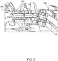
- Fig. 2 illustrates splitter 22.
- a first hose 20a is connected an inlet 22a of the splitter 22, a second hose 20b is connected to a first outlet 22b of the splitter 22, and a third hose 20c is connected to a second outlet 22c of the splitter 22.
- the first hose 20a is configured to receive a commodity (such as seed) from the hopper 16 and direct the seeds into the inlet 22a of the splitter 22. Seed is then split between the second hose 20b (via the first outlet 22b) and the third hose 20c (via the second outlet 22c) and directed to the ground-opening implements which plant the seed in a ground surface.
- the illustrated second hose 20b is in the front seeding rank 12 and the illustrated third hose 20c is in the rear seeding rank 14.
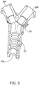
- Fig. 3 illustrates a flow blocking element 26 that includes a metal clip.
- the illustrated flow blocking element 26 is inserted into the first outlet 22b of the splitter 22 to block flow of seed though the first outlet 22b and therefore block flow through the second hose 20b.
- the same flow blocking element 26 can be removed and inserted into the second outlet 22c of the splitter 22 to block flow of seed through the second outlet 22c to thereby block flow of seed through the third hose 20c.
- the flow blocking element 26 is removed to thereby permit flow through the first outlet 22b and the second outlet 22c of the splitter.
- Fig. 4 illustrates one link support arm 28 and one height adjustment arm 30.
- a first ground of link support arms 28 and height adjustment arms 30 are connected to the front seeding rank 12 and a second ground of link support arms 28 and height adjustment arms 30 are connected to the rear seeding rank 14.
- the front and rear seeding ranks 12, 14 can be used independently by either being raised when not in use or lowered to be used for seeding.
- the first group of link supports arms 28 and height adjustment arms 30 are positioned on the front seeding rank 12 to retain the front seeding rank 12 in the lowered, raised and transport positions respectively.
- Fig. 4 specifically illustrates three apertures on the link support arm 28 for the lowered, raised and transportation positions, respectively.
- the illustrated height adjustment arm 39 is connected to the bottom-most aperture on the link support arm 28, which corresponds to the lowered position.
- the second group of link support arms 28 and height adjustment arms 30 are positioned on the rear seeding rank 14 to retain the rear seeding rank 14 in the lowered, raised and transport positions, respectively.
- flow blocking elements 26 such as metal clip in Fig. 3
- flow blocking elements 26 are inserted into the portions of the seed splitters 22 associated with the raised rank 12, 14 to block flow through the portions of the seed splitters 22 directing flow to the raised rank 12, 14.
- flow blocking elements 26 such as the metal clip
- the rear seeding rank 14 is raised, flow blocking elements 26, such as the metal clip, are inserted into each of the second outlets 22c of the splitters 22.
- the seed splitter 22 is a mechanical device which does not guarantee the 50-50% seed flow between front and rear ranks 12, 14. In some configurations, one of the ranks 12, 14 may get around 7-10% extra seeds than the other one of the ranks 12, 14. When both ranks 12 and 14 are selected and no flow blocking elements 26 are installed, it is typically desired to divide the flow evenly between the front rank 12 and the rear rank 14.
- One possible method for automating rank selection and seed blocking permits the operator to select one or both of the front rank 12 and the rear rank 14 from the cab 18.
- the selected rank(s) move into the lowered position, the unselected rank moves into the raised position, and seed is inhibited from entering the unselected rank but is permitted to enter the selected rank.
- the ranks can move either prior to, concurrent with, or after flow through the unselected ranks is blocked.
- the method also provides the operator with the ability to balance the seed flow between the ranks in the event that both the front rank 12 and the rear rank 14 are selected.
- the method includes the following steps:
- Fig. 5 illustrates an actuator 32 connected to the height adjustment arm 30 and a plunger 34 that is moved by the actuator 32.
- the illustrated plunger 34 is moveable between a retracted or unlocked position (shown in solid lines) and a protruding or locked position (shown in phantom lines).
- the actuator 32 moves the plunger 34 axially in response to one or more signals from the controller 24.
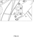
- Fig. 6 illustrates the plunger 34 in alignment with one of the apertures on the link support arm 28.
- the height adjustment arm 30 and the plunger 34 are moved in response to one or more signals from the controller 24.
- one or more proximity sensors and/or cameras are included near the plunger 34 to confirm that the plunger 34 is adjacent one of the apertures on the link support arm 28 prior to the plunger 34 being moved into the protruding position.
- Fig. 7 illustrates one of the possible splitter flow blocking elements as a linear actuator 40.
- the linear actuator 40 includes a motor 42 and a linearly moving portion 44 that can extend across one outlet (22b or 22c) of the splitter 22 to inhibit flow through the respective outlet of the splitter 22.
- the motor 42 is electrically connected to the controller 24 to extend or retract the linearly moving portion 44 based upon the signal from the controller 24.
- a first linear actuator 40 is positioned in the first outlet 22b of the splitter 22 and a second linear actuator 40 is positioned in the second outlet 22c of the splitter 22.
- the controller 24 can send a signal to the linear actuators 40 to move the respective linearly moving portion 44 to positions between fully extended and fully retracted to adjust the flow balance between the two outlets of the splitter 22.
- the flow through the first outlet 22b and the second outlet 22c can be balanced by moving one or both of the linearly moving portions 44 to positions between fully extended and fully retracted.
- the operator can moving the linearly moving portion 44 to block a portion of the first outlet 22b to thereby direct more of the flow to the second outlet 22c. This can enable the user to achieve an approximately balanced flow between the first outlet 22b and the second outlet 22c.
- Fig. 8 illustrates another splitter flow blocking element 48 that includes a rotating plate 50 that can rotate the rotating plate 50 between a first end position in which flow through the first outlet 22b is completely inhibited, a second end position in which flow though the second outlet 22c is completely inhibited and an number of positions between the first end position and the second end position.
- a motor 52 is electrically connected to the controller 24 to rotate the rotating plate 50 based upon a signal from the controller 24.
- the controller 24 can send a signal to the rotating plate 50 to rotate the rotating plate 50 to positions between the first end position and the second end position to adjust the flow balance between the two outlets 22b, 22c of the splitter 22.
- Fig. 9 illustrates another possible flow blocking element 56 that includes a variable orifice 58.
- the variable orifice 58 of the flow blocking element 56 includes a plurality of moving sections that move between a fully open and a fully closed position.
- One flow blocking element 56 is positioned in the first outlet 22b and one flow blocking element 56 is positioned in the second outlet 22c.
- a motor is electrically connected to the controller 24 to move the moving sections of the respective variable orifices 58 based upon signals from the controller 24.
- the variable orifices 58 are separately controlled, such that the variable orifice 58 in the first outlet 22b can be opened or closed separately from the variable orifice 58 in the second outlet 22c being opened or closed.
- the controller 24 can send signals to one or both of the variable orifice flow blocking elements 56 to move the respective moving sections of the variable orifices 58 to positions between the fully open position and the fully closed position to adjust the flow balance between the first and second outlets 22b, 22c of the splitter 22.
- the flow blocking elements 40, 48 and 56 shown in Figs. 7-9 permit each row to be controlled independently at the respective splitters 22.
- the flow blocking elements 40, 48 and 56 also permit the user to adjust the flow of seeds through the first and second outlets 22b, 22c of the splitters 22 to the front rank 12 and to the rear rank 14 to achieve the desired split of seeds between ranks (i.e., fifty percent of the seeds to the front rank 12 and fifty percent of seeds to the rear rank 14).
- Fig. 10 illustrates another possible flow blocking configuration in which the hoses 20 are routed such that a first set of hoses 20a is dedicated to the front rank 12 and a second set of hoses 20b is dedicated to the rear rank 14.
- the splitters 22 direct seed flow to two adjacent rows of the same rank (i.e. to the front rank 12 or to the rear rank 14).
- a first one of the first group of hoses 20a directs flow to a first outlet R1 and a second outlet R3, which are both positioned in the front rank 12.
- the first set of hoses 20a includes four hoses directing flow to eight outlets in the front rank 12 and the second set of hoses 20b includes four hoses directing flow to eight outlets in the rear rank 14.
- Other quantities and configurations of hoses 20 and splitters 22 are possible.
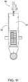
- Fig. 11 illustrates another flow blocking element 62 which is a moving plate 64 positioned at a wall of the hopper 16 adjacent each of the first set of hoses 20a and adjacent each of the second set of hoses 20b to block flow through the respective hose 20.
- the moving plate 64 of the flow blocking element 62 is moved between a closed position and an open position by an actuator 66.
- the actuator 66 is electrically connected to the controller 24 to move the moving plate 64 of the flow blocking element 62 between the closed position and the open position based upon a signal from the controller 24.
- one or more sensors are positioned adjacent the moving plate 64 of the flow blocking element 62 to confirm the position of the moving plate 64.
- the sensor can be a proximity sensor, a magnetic sensor or other suitable sensor.
- the sensor is electrically connected to the controller 24 to provide confirmation of the position of the respective moving plate flow 64 to the user.
- the present disclosure automates a previously manual process to greatly reduce the time and effort required by the user to raise or lower the desired ranks and to block flow through the hoses in the unused ranks. Specifically, the user can raise or lower the desired ranks, lock the ranks in the desired position, and block flow through the hoses in the unused ranks all from the cab of the work vehicle. In some configurations, a flow balance of seeds between the front rank 12 and the rear rank 14 can be adjusted and controlled by a user from the cab 18 of the seeder machine 10.
Landscapes
- Life Sciences & Earth Sciences (AREA)
- Soil Sciences (AREA)
- Environmental Sciences (AREA)
- Engineering & Computer Science (AREA)
- Mechanical Engineering (AREA)
- Fertilizing (AREA)
- Sowing (AREA)
- Soil Working Implements (AREA)
- Agricultural Machines (AREA)
Abstract
to send a third signal to move the first flow blocking element (26) between the first position and the second position, and to send a fourth signal to move the second flow blocking element (26) between the first position and the second position. Further a respective method and a control system is disclosed.
Description
- The present disclosure relates to selection of one or more ranks in a work vehicle.
- In one embodiment, the disclosure provides a work vehicle including a frame, a ground-engaging implement connected to the frame to support the frame above a ground surface, a hopper configured to retain a commodity, and a first ground-opening implement that opens the ground surface. The first ground-opening implement is connected to the frame for movement with respect to the frame between a first stowed position and a first deployed position. A first lock retains the first ground-opening implement in the first stowed position and in the first deployed position. A first actuator opens the first lock to permit the first ground-engaging implement to move between the first stowed position and the first deployed position, and closes the first lock to retain the first ground-engaging implement in a selected one of the first stowed position and the first deployed position. A first hose is connected to the hopper to deliver the commodity to the ground surface adjacent the first ground-opening implement. A first flow blocking element inhibits flow through the first hose in a first position and permits flow through the first hose in a second position. A second ground-opening implement opens the ground surface and is connected to the frame for movement with respect to the frame between a second stowed and a second deployed position. A second lock retains the second ground-opening implement in the second stowed position and in the second deployed position. A second actuator opens the second lock to permit the second ground-engaging implement to move between the second stowed position and the second deployed position, and closes the second lock to retain the second ground-engaging implement in a selected one of the second stowed position and the second deployed position. A second hose is connected to the hopper to deliver the commodity to the ground surface adjacent the second ground-opening implement. A second flow blocking element inhibits flow through the second hose in a first position and permits flow through the second hose in a second position. A user interface receives an input from the user and a controller is in communication with the user interface. In response to the input from the user, the controller sends a first signal to the first actuator to lock and unlock the first lock, sends a second signal to the second actuator to lock and unlock the second lock, sends a third signal to the move the first flow blocking element between the first position and the second position, and sends a fourth signal to the move the first flow blocking element between the first position and the second position.
- In another embodiment the disclosure provides a method of rank selection and seed flow control of a work vehicle. The method includes raising an unselected rank with a first actuator in response to input from a user via a user interface, and retaining the unselected rank in a raised position with a first lock in response to input from the user via the user interface. The method further includes moving a first flow blocking element into a closed position in response to input from the user via the user interface, and inhibiting flow of a commodity to the unselected rank through a first hose with the first flow blocking element. The method further includes lowering a selected rank with a second actuator in response to input from the user via the user interface, and retaining the selected rank in a lowered position with a second lock in response to input from the user via the user interface. The method further includes moving a second flow blocking element into an open position in response to input from the user via the user interface, permitting flow of the commodity to the selected rank through a second hose with the second flow blocking element, and moving the commodity from a hopper through the second hose to a ground surface.
- In another embodiment, the disclosure provides a control system including a user interface that receives an input from the user, and a controller in communication with the user interface. In response to the input from the user, the controller sends a first signal to a first actuator to unlock a first lock, sends a second signal to a first ground-engaging implement to move the first ground-engaging implement into a stowed position, sends a third signal to the first actuator to lock first lock to retain the first ground-engaging implement in the stowed position, sends a fourth signal to a first flow blocking element to inhibit flow through a first hose with a flow blocking element, sends a fifth signal to a second actuator to unlock a second lock, sends a sixth signal to a second ground-engaging implement to move the second ground-engaging implement into a deployed position, sends a seventh signal to the second actuator to lock the second lock to retain the second ground-engaging implement in the deployed position, and sends an eighth signal to a second flow blocking element to permit flow through a second hose around the flow blocking element.
- Other aspects of the disclosure will become apparent by consideration of the detailed description and accompanying drawings.
-
-
Fig. 1 is a perspective view of a work vehicle according to some embodiments. -
Fig. 2 is a perspective view of a splitter and hoses. -
Fig. 3 is a top view of the splitter. -
Fig. 4 is a side view of the actuator and lock. -
Fig. 5 is a front view of the actuator and lock. -
Fig. 6 is a close up view of the lock. -
Fig. 7 is a side view of one embodiment of a flow blocking element. -
Fig. 8 is a perspective view of one embodiment of a flow blocking element. -
Fig. 9 is a side schematic view of one embodiment of a flow blocking element. -
Fig. 10 is a schematic view of a hose configuration according to some embodiments. -
Fig. 11 is a schematic view of a flow meter and a gate. - Before any embodiments of the disclosure are explained in detail, it is to be understood that the disclosure is not limited in its application to the details of construction and the arrangement of components set forth in the following description or illustrated in the following drawings. The disclosure is capable of other embodiments and of being practiced or of being carried out in various ways.
-
Fig. 1 illustrates aseeder machine 10 having afront seeding rank 12, arear seeding rank 14, ahopper 16, anoperator cab 18, a plurality ofhoses 20, a plurality ofsplitters 22, acontroller 24 and auser interface 25. Theseeder machine 10 is supported by a plurality of ground-engaging implements (such as wheels or tracks). Thefront seeding rank 12 and therear seeding rank 14 each have a plurality of ground-opening implements configured to open the ground, position one or more seeds into the open ground, and close the ground after positioning the one or more seeds into the open ground. Theseeder machine 10 is configured to move along a ground surface such that the plurality of ground-opening implements open the ground, position one or more seeds in the ground, and close the ground after positioning the one or more seeds into the open ground. - The plurality of
hoses 20 are fluidly connected to thehopper 16 to direct seeds from thehopper 16 to the plurality ofsplitters 22. A blower or other motive force is utilized to move the seeds through the plurality ofhoses 20. Thesplitters 22 divide the flow through one of thehoses 20 to two separate outlets. In the illustrated embodiment, thesplitters 22 direct flow to one outlet in thefront seeding rank 12 and direct flow to one outlet in therear seeding rank 14. -
Fig. 2 illustratessplitter 22. Afirst hose 20a is connected aninlet 22a of thesplitter 22, asecond hose 20b is connected to afirst outlet 22b of thesplitter 22, and athird hose 20c is connected to asecond outlet 22c of thesplitter 22. Thefirst hose 20a is configured to receive a commodity (such as seed) from thehopper 16 and direct the seeds into theinlet 22a of thesplitter 22. Seed is then split between thesecond hose 20b (via thefirst outlet 22b) and thethird hose 20c (via thesecond outlet 22c) and directed to the ground-opening implements which plant the seed in a ground surface. The illustratedsecond hose 20b is in thefront seeding rank 12 and the illustratedthird hose 20c is in therear seeding rank 14. -
Fig. 3 illustrates aflow blocking element 26 that includes a metal clip. The illustratedflow blocking element 26 is inserted into thefirst outlet 22b of thesplitter 22 to block flow of seed though thefirst outlet 22b and therefore block flow through thesecond hose 20b. The sameflow blocking element 26 can be removed and inserted into thesecond outlet 22c of thesplitter 22 to block flow of seed through thesecond outlet 22c to thereby block flow of seed through thethird hose 20c. In some embodiments, theflow blocking element 26 is removed to thereby permit flow through thefirst outlet 22b and thesecond outlet 22c of the splitter. -
Fig. 4 illustrates onelink support arm 28 and oneheight adjustment arm 30. A first ground of link supportarms 28 andheight adjustment arms 30 are connected to thefront seeding rank 12 and a second ground of link supportarms 28 andheight adjustment arms 30 are connected to therear seeding rank 14. The front and rear seeding ranks 12, 14 can be used independently by either being raised when not in use or lowered to be used for seeding. The first group of link supportsarms 28 andheight adjustment arms 30 are positioned on thefront seeding rank 12 to retain thefront seeding rank 12 in the lowered, raised and transport positions respectively.Fig. 4 specifically illustrates three apertures on thelink support arm 28 for the lowered, raised and transportation positions, respectively. The illustrated height adjustment arm 39 is connected to the bottom-most aperture on thelink support arm 28, which corresponds to the lowered position. The second group of link supportarms 28 andheight adjustment arms 30 are positioned on therear seeding rank 14 to retain therear seeding rank 14 in the lowered, raised and transport positions, respectively. - When one of the
front seeding rank 12 andrear seeding rank 14 is raised,flow blocking elements 26, such as metal clip inFig. 3 , are inserted into the portions of theseed splitters 22 associated with the raisedrank seed splitters 22 directing flow to the raisedrank front seeding rank 12 is raised, flow blocking elements 26 (such as the metal clip) are inserted into each of thefirst outlets 22b of thesplitters 22. When therear seeding rank 14 is raised,flow blocking elements 26, such as the metal clip, are inserted into each of thesecond outlets 22c of thesplitters 22. When both thefront seeding rank 12 and therear seeding rank 14 are lowered, no flow blocking elements are utilized. - Changing rank position has been a manual process which involves much labor and time to accomplish. It often takes at least thirty minutes to one hour to perform the following steps:
- 1) Raise the rank which will not be used and lock the unused rank with a mechanical lock, such as
link support arm 28 andheight adjustment arm 30, - 2) Block seed flow by inserting a
flow blocking element 26, such as metal clip, into the portion of theseed splitter 22 associated with the unused rank on each row, - 3) Change the setting in the software, and
- 4) Run machine and monitor seed flow to ensure seeds are received on correct rows and not received on the unused rank.
- This process is time consuming and labor-intensive for the operator as multiple
link support arms 28 andheight adjustment arms 30 need to be adjusted andmultiple seed splitters 22 needflow blocking elements 26 installed. Further, theseed splitter 22 is a mechanical device which does not guarantee the 50-50% seed flow between front andrear ranks ranks ranks flow blocking elements 26 are installed, it is typically desired to divide the flow evenly between thefront rank 12 and therear rank 14. - One possible method for automating rank selection and seed blocking permits the operator to select one or both of the
front rank 12 and therear rank 14 from thecab 18. In response to the operator selecting one or both of thefront rank 12 and therear rank 14, the selected rank(s) move into the lowered position, the unselected rank moves into the raised position, and seed is inhibited from entering the unselected rank but is permitted to enter the selected rank. The ranks can move either prior to, concurrent with, or after flow through the unselected ranks is blocked. In some embodiments, the method also provides the operator with the ability to balance the seed flow between the ranks in the event that both thefront rank 12 and therear rank 14 are selected. - The method includes the following steps:
- 1. Navigate to setup screen for rank selection on the
user interface 25. The operator selects one or both of thefront seeding rank 12 and therear seeding rank 14. This step occurs first. - 2. The
controller 24 ensures that all meters are stopped and that the machine is not moving. This step occurs second. - 3. The
controller 24 sends signals to theheight adjustment arms 30 to lower the selected rank(s) and to raise the unselected rank. - 4. The
controller 24 sends signals to actuators to lock the selected rank(s) in the lowered position and to lock the unselected rank in the raised position. This step occurs after step 3. - 5. The
controller 24 sends signals to theflow blocking elements 26 to permit or inhibit seed flow through thesplitter outlets
This step can occur before step 3, during step 3, during step 4 or after step 4. - 6. The
controller 24 provides confirmation that theranks controller 24 also notifies the user via theuser interface 25 when the process is complete. -
Fig. 5 illustrates anactuator 32 connected to theheight adjustment arm 30 and aplunger 34 that is moved by theactuator 32. The illustratedplunger 34 is moveable between a retracted or unlocked position (shown in solid lines) and a protruding or locked position (shown in phantom lines). Theactuator 32 moves theplunger 34 axially in response to one or more signals from thecontroller 24. -
Fig. 6 illustrates theplunger 34 in alignment with one of the apertures on thelink support arm 28. Theheight adjustment arm 30 and theplunger 34 are moved in response to one or more signals from thecontroller 24. In some embodiments, one or more proximity sensors and/or cameras are included near theplunger 34 to confirm that theplunger 34 is adjacent one of the apertures on thelink support arm 28 prior to theplunger 34 being moved into the protruding position. - After the selected rank(s) have been moved into the lowered position and the unselected rank (if any) has been moved into the raised position, the seed flow to the unselected rank (if any) needs to be inhibited. Seeds can be blocked at the splitter level or at the meter level.
Fig. 7 illustrates one of the possible splitter flow blocking elements as alinear actuator 40. Thelinear actuator 40 includes amotor 42 and a linearly movingportion 44 that can extend across one outlet (22b or 22c) of thesplitter 22 to inhibit flow through the respective outlet of thesplitter 22. Themotor 42 is electrically connected to thecontroller 24 to extend or retract the linearly movingportion 44 based upon the signal from thecontroller 24. A firstlinear actuator 40 is positioned in thefirst outlet 22b of thesplitter 22 and a secondlinear actuator 40 is positioned in thesecond outlet 22c of thesplitter 22. In some embodiments, thecontroller 24 can send a signal to thelinear actuators 40 to move the respective linearly movingportion 44 to positions between fully extended and fully retracted to adjust the flow balance between the two outlets of thesplitter 22. The flow through thefirst outlet 22b and thesecond outlet 22c can be balanced by moving one or both of the linearly movingportions 44 to positions between fully extended and fully retracted. For example, if theuser interface 25 indicates that 60% of the flow is moving through thefirst outlet 22b, the operator can moving the linearly movingportion 44 to block a portion of thefirst outlet 22b to thereby direct more of the flow to thesecond outlet 22c. This can enable the user to achieve an approximately balanced flow between thefirst outlet 22b and thesecond outlet 22c. -
Fig. 8 illustrates another splitterflow blocking element 48 that includes arotating plate 50 that can rotate therotating plate 50 between a first end position in which flow through thefirst outlet 22b is completely inhibited, a second end position in which flow though thesecond outlet 22c is completely inhibited and an number of positions between the first end position and the second end position. Amotor 52 is electrically connected to thecontroller 24 to rotate therotating plate 50 based upon a signal from thecontroller 24. In some embodiments, thecontroller 24 can send a signal to therotating plate 50 to rotate therotating plate 50 to positions between the first end position and the second end position to adjust the flow balance between the twooutlets splitter 22. -
Fig. 9 illustrates another possibleflow blocking element 56 that includes avariable orifice 58. Thevariable orifice 58 of theflow blocking element 56 includes a plurality of moving sections that move between a fully open and a fully closed position. Oneflow blocking element 56 is positioned in thefirst outlet 22b and oneflow blocking element 56 is positioned in thesecond outlet 22c. A motor is electrically connected to thecontroller 24 to move the moving sections of the respectivevariable orifices 58 based upon signals from thecontroller 24. Thevariable orifices 58 are separately controlled, such that thevariable orifice 58 in thefirst outlet 22b can be opened or closed separately from thevariable orifice 58 in thesecond outlet 22c being opened or closed. In some embodiments, thecontroller 24 can send signals to one or both of the variable orificeflow blocking elements 56 to move the respective moving sections of thevariable orifices 58 to positions between the fully open position and the fully closed position to adjust the flow balance between the first andsecond outlets splitter 22. - The
flow blocking elements Figs. 7-9 permit each row to be controlled independently at therespective splitters 22. Theflow blocking elements second outlets splitters 22 to thefront rank 12 and to therear rank 14 to achieve the desired split of seeds between ranks (i.e., fifty percent of the seeds to thefront rank 12 and fifty percent of seeds to the rear rank 14). -
Fig. 10 illustrates another possible flow blocking configuration in which thehoses 20 are routed such that a first set ofhoses 20a is dedicated to thefront rank 12 and a second set ofhoses 20b is dedicated to therear rank 14. Thesplitters 22 direct seed flow to two adjacent rows of the same rank (i.e. to thefront rank 12 or to the rear rank 14). For example, a first one of the first group ofhoses 20a directs flow to a first outlet R1 and a second outlet R3, which are both positioned in thefront rank 12. In the illustrated embodiments, the first set ofhoses 20a includes four hoses directing flow to eight outlets in thefront rank 12 and the second set ofhoses 20b includes four hoses directing flow to eight outlets in therear rank 14. Other quantities and configurations ofhoses 20 andsplitters 22 are possible. -
Fig. 11 illustrates anotherflow blocking element 62 which is a movingplate 64 positioned at a wall of thehopper 16 adjacent each of the first set ofhoses 20a and adjacent each of the second set ofhoses 20b to block flow through therespective hose 20. The movingplate 64 of theflow blocking element 62 is moved between a closed position and an open position by anactuator 66. Theactuator 66 is electrically connected to thecontroller 24 to move the movingplate 64 of theflow blocking element 62 between the closed position and the open position based upon a signal from thecontroller 24. - In some embodiments, one or more sensors are positioned adjacent the moving
plate 64 of theflow blocking element 62 to confirm the position of the movingplate 64. The sensor can be a proximity sensor, a magnetic sensor or other suitable sensor. The sensor is electrically connected to thecontroller 24 to provide confirmation of the position of the respective movingplate flow 64 to the user. - The present disclosure automates a previously manual process to greatly reduce the time and effort required by the user to raise or lower the desired ranks and to block flow through the hoses in the unused ranks. Specifically, the user can raise or lower the desired ranks, lock the ranks in the desired position, and block flow through the hoses in the unused ranks all from the cab of the work vehicle. In some configurations, a flow balance of seeds between the
front rank 12 and therear rank 14 can be adjusted and controlled by a user from thecab 18 of theseeder machine 10.
Claims (12)
wherein the second flow blocking element (26) is connected to a second outlet (22c) of the splitter such that flow through the second outlet (22c) of the splitter into the third hose (20c) is inhibited when the second flow blocking element (26) configured is in the first position and is permitted when the second flow blocking element (26) is in a second position.
lowering the first rank (12) with the first actuator (32) in response to input from the user via the user interface (25);
retaining the first rank (12) in a lowered position with the first lock in response to input from the user via the user interface (25);
moving the first flow blocking element (26) into an open position in response to input from the user via the user interface (25);
permitting flow of the commodity to the first rank (12) through the second hose (20b) with the first flow blocking element (26); and
moving the commodity from the hopper (16) through the second hose (20b) to a ground surface.
partially closing the first flow blocking element (26) to thereby adjust a flow rate through the second hose (20b), and/or
partially closing the second flow blocking element (26) to thereby adjust a flow rate through the third hose (20c),
wherein the sixth signal is sent to a fourth actuator (30) configured to move the second ground-engaging implement between a stowed and the deployed position.
wherein the controller (24) is further configured to receive a first flow rate from a first meter indicative of a flow rate of commodity through the second hose (20b), and to receive a second flow rate from a second meter indicative of a flow rate of commodity through the third hose (20c), wherein the controller (24) is further configured to send an eleventh signal to the user interface (25) to display the first flow rate to the user and is configured to send a twelfth signal to the user interface (25) to display the second flow rate to the user.
send a thirteenth signal to move the second flow blocking element (26) into a closed position in response to input from the user via the user interface (25) to inhibit flow though the third hose (20c) with second flow blocking element (26), and/or
send a fourteenth signal to move the first flow blocking element (26) into an open position in response to input from the user via the user interface (25) to permit flow through the second hose (20b) around the first flow blocking element (26).
Applications Claiming Priority (1)
| Application Number | Priority Date | Filing Date | Title |
|---|---|---|---|
| US16/535,952 US11197412B2 (en) | 2019-08-08 | 2019-08-08 | Automatic rank selection |
Publications (1)
| Publication Number | Publication Date |
|---|---|
| EP3772268A1 true EP3772268A1 (en) | 2021-02-10 |
Family
ID=71950523
Family Applications (1)
| Application Number | Title | Priority Date | Filing Date |
|---|---|---|---|
| EP20189626.3A Withdrawn EP3772268A1 (en) | 2019-08-08 | 2020-08-05 | Work vehicle, method for operating and control system for such |
Country Status (6)
| Country | Link |
|---|---|
| US (1) | US11197412B2 (en) |
| EP (1) | EP3772268A1 (en) |
| AR (1) | AR119368A1 (en) |
| AU (1) | AU2020204390B2 (en) |
| BR (1) | BR102020012444A2 (en) |
| CA (1) | CA3086121A1 (en) |
Citations (4)
| Publication number | Priority date | Publication date | Assignee | Title |
|---|---|---|---|---|
| US20070079883A1 (en) * | 2005-07-12 | 2007-04-12 | Snipes Terry L | Airflow divider with shutoff |
| US20090078178A1 (en) * | 2007-09-21 | 2009-03-26 | One Pass Implements Inc. | Air seeder/fertilizer apparatus having metering means and distribution manifold with selectively openable ports |
| WO2013105021A1 (en) * | 2012-01-09 | 2013-07-18 | Cnh Canada, Ltd. | Rotary flow divider assembly for agricultural product distribution system |
| CA2902922A1 (en) * | 2015-09-03 | 2016-03-08 | Bourgault Industries Ltd. | Air seeder for singulated and bulk seeding |
Family Cites Families (3)
| Publication number | Priority date | Publication date | Assignee | Title |
|---|---|---|---|---|
| US7726251B1 (en) | 2009-03-11 | 2010-06-01 | Deere & Company | Agricultural seeding apparatus and method for seed placement synchronization between multiple rows |
| US7966954B2 (en) | 2009-06-11 | 2011-06-28 | Cnh America Llc | Air/product flow splitting apparatus for use with product distribution system of an agricultural seeding machine |
| US8770120B2 (en) | 2011-05-24 | 2014-07-08 | Cnh Industrial Canada, Ltd. | Method and apparatus for distributing seed from a central source to a plurality of seed metering units of an agricultural seeding machine |
-
2019
- 2019-08-08 US US16/535,952 patent/US11197412B2/en active Active
-
2020
- 2020-06-18 BR BR102020012444-7A patent/BR102020012444A2/en active Search and Examination
- 2020-06-30 AU AU2020204390A patent/AU2020204390B2/en active Active
- 2020-07-07 CA CA3086121A patent/CA3086121A1/en active Pending
- 2020-07-07 AR ARP200101918A patent/AR119368A1/en active IP Right Grant
- 2020-08-05 EP EP20189626.3A patent/EP3772268A1/en not_active Withdrawn
Patent Citations (4)
| Publication number | Priority date | Publication date | Assignee | Title |
|---|---|---|---|---|
| US20070079883A1 (en) * | 2005-07-12 | 2007-04-12 | Snipes Terry L | Airflow divider with shutoff |
| US20090078178A1 (en) * | 2007-09-21 | 2009-03-26 | One Pass Implements Inc. | Air seeder/fertilizer apparatus having metering means and distribution manifold with selectively openable ports |
| WO2013105021A1 (en) * | 2012-01-09 | 2013-07-18 | Cnh Canada, Ltd. | Rotary flow divider assembly for agricultural product distribution system |
| CA2902922A1 (en) * | 2015-09-03 | 2016-03-08 | Bourgault Industries Ltd. | Air seeder for singulated and bulk seeding |
Also Published As
| Publication number | Publication date |
|---|---|
| CA3086121A1 (en) | 2021-02-08 |
| BR102020012444A2 (en) | 2021-08-17 |
| US20210037698A1 (en) | 2021-02-11 |
| AU2020204390A1 (en) | 2021-02-25 |
| AU2020204390B2 (en) | 2026-03-05 |
| US11197412B2 (en) | 2021-12-14 |
| AR119368A1 (en) | 2021-12-15 |
Similar Documents
| Publication | Publication Date | Title |
|---|---|---|
| US20230217848A1 (en) | Toolbar with hydraulic height control | |
| US11140805B2 (en) | Independent ground engaging tool depth control | |
| US11140806B2 (en) | Agricultural toolbar apparatus, systems, and methods | |
| US10959418B2 (en) | Automatic application rate and section control based on actual planting data | |
| EP1273215B1 (en) | Agricultural machinery combination | |
| EP2042276B1 (en) | Agricultural vehicle and method for calculating the position | |
| CA2866045C (en) | Remote leveling of tillage implements using three way valves | |
| US20180153088A1 (en) | Automated leveling and depth control system of a work machine and method thereof | |
| US20040016556A1 (en) | Electrohydraulic control system for implement lift cylinders | |
| US9161488B2 (en) | Wing lifting system for an agricultural implement | |
| US10667454B2 (en) | Hydraulic control system of an implement for a work machine and method thereof | |
| US10299423B2 (en) | Computer controlled hydraulic bleed sequence | |
| EP3065526A1 (en) | Implement weight management systems, methods, and apparatus | |
| US11166402B2 (en) | Tillage apparatus, systems, and methods | |
| US11197412B2 (en) | Automatic rank selection | |
| EP3075246A1 (en) | Agricultural machine and security method | |
| EP3400769B1 (en) | Agricultural machine and method for operating an agricultural machine | |
| DE19520166A1 (en) | Concrete pump multi-element outrigger-type cantilevered pipe control arrangement | |
| CA3136009A1 (en) | Sowing machine having individual coulter pressure control | |
| EP3704925B1 (en) | Sowing machine | |
| US11785872B2 (en) | Closed-loop actively damped position control of an implement stabilizer wheel | |
| US11304353B2 (en) | Closed-loop proportional position control of an implement stabilizer wheel | |
| EP4706368A1 (en) | Methods of using agricultural implements with variable row spacing | |
| CA1294852C (en) | Hydraulic control circuit for a master cylinder with multiple limit position | |
| WO2024042426A1 (en) | Multi-row unit controller for controlling and monitoring row units of an agricultural implement and a related method |
Legal Events
| Date | Code | Title | Description |
|---|---|---|---|
| PUAI | Public reference made under article 153(3) epc to a published international application that has entered the european phase |
Free format text: ORIGINAL CODE: 0009012 |
|
| STAA | Information on the status of an ep patent application or granted ep patent |
Free format text: STATUS: THE APPLICATION HAS BEEN PUBLISHED |
|
| AK | Designated contracting states |
Kind code of ref document: A1 Designated state(s): AL AT BE BG CH CY CZ DE DK EE ES FI FR GB GR HR HU IE IS IT LI LT LU LV MC MK MT NL NO PL PT RO RS SE SI SK SM TR |
|
| AX | Request for extension of the european patent |
Extension state: BA ME |
|
| RIN1 | Information on inventor provided before grant (corrected) |
Inventor name: LSSRANI, MANOJ Inventor name: EKHE, SANDEEP Inventor name: PARALIKAR, ASHISH Inventor name: KALE, MANDAR MHALSAKANT Inventor name: STALLIN, SARAVANAN |
|
| STAA | Information on the status of an ep patent application or granted ep patent |
Free format text: STATUS: REQUEST FOR EXAMINATION WAS MADE |
|
| 17P | Request for examination filed |
Effective date: 20210810 |
|
| RBV | Designated contracting states (corrected) |
Designated state(s): AL AT BE BG CH CY CZ DE DK EE ES FI FR GB GR HR HU IE IS IT LI LT LU LV MC MK MT NL NO PL PT RO RS SE SI SK SM TR |
|
| STAA | Information on the status of an ep patent application or granted ep patent |
Free format text: STATUS: EXAMINATION IS IN PROGRESS |
|
| 17Q | First examination report despatched |
Effective date: 20241025 |
|
| STAA | Information on the status of an ep patent application or granted ep patent |
Free format text: STATUS: THE APPLICATION IS DEEMED TO BE WITHDRAWN |
|
| 18D | Application deemed to be withdrawn |
Effective date: 20250226 |