EP3772168A1 - Detection of a failure of a power module based on operating conditions - Google Patents
Detection of a failure of a power module based on operating conditions Download PDFInfo
- Publication number
- EP3772168A1 EP3772168A1 EP19306001.9A EP19306001A EP3772168A1 EP 3772168 A1 EP3772168 A1 EP 3772168A1 EP 19306001 A EP19306001 A EP 19306001A EP 3772168 A1 EP3772168 A1 EP 3772168A1
- Authority
- EP
- European Patent Office
- Prior art keywords
- power module
- operating conditions
- temperature
- failure
- model
- Prior art date
- Legal status (The legal status is an assumption and is not a legal conclusion. Google has not performed a legal analysis and makes no representation as to the accuracy of the status listed.)
- Pending
Links
Images


Classifications
-
- G—PHYSICS
- G06—COMPUTING OR CALCULATING; COUNTING
- G06F—ELECTRIC DIGITAL DATA PROCESSING
- G06F1/00—Details not covered by groups G06F3/00 - G06F13/00 and G06F21/00
- G06F1/26—Power supply means, e.g. regulation thereof
- G06F1/28—Supervision thereof, e.g. detecting power-supply failure by out of limits supervision
-
- H—ELECTRICITY
- H02—GENERATION; CONVERSION OR DISTRIBUTION OF ELECTRIC POWER
- H02M—APPARATUS FOR CONVERSION BETWEEN AC AND AC, BETWEEN AC AND DC, OR BETWEEN DC AND DC, AND FOR USE WITH MAINS OR SIMILAR POWER SUPPLY SYSTEMS; CONVERSION OF DC OR AC INPUT POWER INTO SURGE OUTPUT POWER; CONTROL OR REGULATION THEREOF
- H02M7/00—Conversion of AC power input into DC power output; Conversion of DC power input into AC power output
- H02M7/003—Constructional details, e.g. physical layout, assembly, wiring or busbar connections
-
- G—PHYSICS
- G01—MEASURING; TESTING
- G01R—MEASURING ELECTRIC VARIABLES; MEASURING MAGNETIC VARIABLES
- G01R31/00—Arrangements for testing electric properties; Arrangements for locating electric faults; Arrangements for electrical testing characterised by what is being tested not provided for elsewhere
- G01R31/003—Environmental or reliability tests
-
- H—ELECTRICITY
- H03—ELECTRONIC CIRCUITRY
- H03K—PULSE TECHNIQUE
- H03K17/00—Electronic switching or gating, i.e. not by contact-making and –breaking
- H03K17/08—Modifications for protecting switching circuit against overcurrent or overvoltage
-
- H—ELECTRICITY
- H02—GENERATION; CONVERSION OR DISTRIBUTION OF ELECTRIC POWER
- H02M—APPARATUS FOR CONVERSION BETWEEN AC AND AC, BETWEEN AC AND DC, OR BETWEEN DC AND DC, AND FOR USE WITH MAINS OR SIMILAR POWER SUPPLY SYSTEMS; CONVERSION OF DC OR AC INPUT POWER INTO SURGE OUTPUT POWER; CONTROL OR REGULATION THEREOF
- H02M1/00—Details of apparatus for conversion
- H02M1/32—Means for protecting converters other than automatic disconnection
- H02M1/327—Means for protecting converters other than automatic disconnection against abnormal temperatures
-
- H—ELECTRICITY
- H03—ELECTRONIC CIRCUITRY
- H03K—PULSE TECHNIQUE
- H03K17/00—Electronic switching or gating, i.e. not by contact-making and –breaking
- H03K17/08—Modifications for protecting switching circuit against overcurrent or overvoltage
- H03K2017/0806—Modifications for protecting switching circuit against overcurrent or overvoltage against excessive temperature
-
- H—ELECTRICITY
- H10—SEMICONDUCTOR DEVICES; ELECTRIC SOLID-STATE DEVICES NOT OTHERWISE PROVIDED FOR
- H10W—GENERIC PACKAGES, INTERCONNECTIONS, CONNECTORS OR OTHER CONSTRUCTIONAL DETAILS OF DEVICES COVERED BY CLASS H10
- H10W40/00—Arrangements for thermal protection or thermal control
Definitions
- the present invention relates to the detection of aging/failure in an industrial device, such as, in particular while not exclusively, a power module.
- a power module is a physical containment for power semiconductor devices used in power systems for converting electrical energy, such as DC converters, DC to AC inverters, AC-DC-AC converters, etc.
- a power module can be integrated in motor drives, Uninterruptible Power Source, UPS, or Photo Voltaic, PV, inverter.
- Power electronic converters are usually among the most critical assemblies in terms of failure level, lifetime and maintenance costs, in the field of renewable energy.
- Motor drives are one of the most used power electronic converters in industrial applications: they drive electric motors of pumps, fans and conveyer belts, they move hoisting vehicles and elevators.
- Power modules generally include components such as diodes, Metal Oxyde Semiconductor Field Effect device, MOSFET or Insulated Gate Bipolar Transistors, IGBTs.
- power modules with IGBT, MOSFET and diodes are key components. In operation, they are prone to different environmental and functional stress factors, such as the ambient temperature, thermal cycling, vibrations, humidity, etc.
- thermomechanical damage accumulation Due to power and thermal cycling, the power modules are subjected to thermomechanical damage accumulation, overvoltage or overcurrent, which affects their lifetime and therefore impacts on the power modules reliability.
- Some of the failures of power modules may be due to solder delamination between the dies and the ceramic substrate inside of the power module or between a power module baseplate and the heatsink. They may also be due to thermal grease aging between the power module and the heatsink. They may also be due to wire-bond lift off between the semiconductor and electrical contacts of the module. Also, when a fan grid is covered with some dust, the cooling function performed by the fan is less efficient.
- the PoF approach is a methodology based on root-cause failure mechanism analysis and the impact of materials, defects, and stresses on product reliability. For a given component, there could be multiple failure mechanisms, which should be identified individually.
- junction temperature refers to die temperature in electronic components such as the IGBTs.
- junction temperature based on dedicated circuits is a complex task and remains difficult to implement for determining the junction temperature in real switching applications such as Pulse Width Modulation, PWM, operations using IGBTs in frequency converters.
- PWM Pulse Width Modulation
- a first aspect of the invention concerns a method for detecting a failure of a power module, the method comprising the following operations:
- the first temperature sensor may be a Negative Temperature Coefficient, NTC, sensor.
- NTC sensor The benefit of an NTC sensor is its time constant which is much lower than the time constant of other sensors and which allows to quickly detect temperature variations. It is also to be noted that most of the power modules natively include an NTC sensor. However, it is merely used in the prior art systems to protect the power module against overtemperature. Using an NTC sensor therefore does not impact the cost the power module as it is generally already present in it.
- the first temperature sensor may be arranged for measuring the temperature on a die of the power module.
- the method may further comprise acquiring at least one second temperature value from a second temperature sensor located in the vicinity of a heatsink associated with the power module, and the current operating conditions and the first and second temperature values may be compared with the at least one stored model.
- the method may further comprise:
- This embodiment enables to improve the accuracy of the detection of failure.
- the method may further comprise determining a type of failure of the power module based on the comparison of the current operating conditions and the first and second temperature values with the at least one stored model.
- the method may further comprise acquiring at least one ambient temperature value and the current operating conditions, the first temperature value and the ambient temperature may be compared with the at least one stored model.
- the operating conditions may comprise any combination of the following elements :
- the at least one model may be determined during a preliminary phase comprising :
- the operating conditions of the power module can be controlled to acquire respective regular temperature values during the preliminary phase.
- an alarm can be generated when the failure of the power module is determined.
- the method comprises, before acquiring the first temperature value, detecting that the power module is in stable operating conditions.
- a second aspect of the invention concerns a non-transitory computer readable storage medium, with a computer program stored thereon, said computer program comprising instructions for, when executed by a processor, carrying out the steps of a method according to the first aspect of the invention.
- a third aspect of the invention concerns a device configured for detecting a failure of a power module, the device comprising:
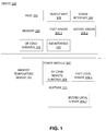
- a device 100 for detecting a failure, and optionally a type of failure, in a power module 107 according to some embodiments of the invention.
- the device 100 can be integrated in a system comprising the power module 107.
- the power module 107 can be integrated in a larger power system such as a power converter for example (DC converters, DC to AC inverters, AC-DC-AC converters, etc).
- a power converter for example (DC converters, DC to AC inverters, AC-DC-AC converters, etc).
- DC converters DC to AC inverters
- AC-DC-AC converters AC-DC-AC converters
- the power module 107 which can be any equipment participating in a power system and comprising elements such as diodes, MOSFETS and/or Insulated Gate Bipolar Transistors, IGBTs.
- the power module 107 may have a layer structure comprising chips mounted on substrates, the substrates being mounted on baseplates and/or heatsink 111.
- the power module 107 may for example consist of an assembly of numerous dies (depending on a power rating).
- the power module 107 may comprise a combination of diodes and IGBTs corresponding to respective dies.
- the power module 107 is associated with a heatsink 111 that is configured for dissipating the heat generated by the power module 107.
- the device 100 comprises at least a first sensor 101.1 that is configured for acquiring first temperature values representative of the temperature of the power module 107, and a second sensor 101.2 that is configured for acquiring second temperature values representative of the temperature of the power module 107.
- the device 100 can be a probe where the sensors 101.1 and 101.2 are movable to be placed in the vicinity of the power module 107 and of the heatsink 111, respectively.
- the first and second sensors are directly integrated on the power module 107 and the heatsink 111 as first and second local sensors 108.1 and 108.2 configured to respectively acquire the first and second temperature values, instead of first and second sensors 101.1 and 101.2.
- the device 100 may comprise a communication interface 104 that is configured to communicate with the at least two first and second remote sensors 108.1 and 108.2 located in the vicinity or inside of the power module 107 and the heatsink 111.
- the first local sensor 108.1 is configured for acquiring first temperature values representative of the temperature of the power module 107
- the second local sensor 108.2 is configured for acquiring second temperature values representative of the temperature of the heatsink 111.
- the first (local) sensor 101.1 or 108.1 may be a Negative Temperature Coefficient, NTC, sensor.
- NTC Negative Temperature Coefficient
- the benefit of an NTC sensor is its time constant which is much lower than the time constant of other sensors and which allows to quickly detect temperature variations. It is also to be noted that most of the power modules natively include an NTC sensor. However, it is merely used in the prior art systems to protect the power module against overtemperature.
- the system may comprise a third sensor 112 that may be an ambient temperature sensor, configured to measure the ambient temperature, such as an ambient temperature of a room in which the power module 107 is located.
- the ambient temperature sensor 112 can be integrated in the device 100 or can be external to it and communicate with it via the communication interface 104.
- Using two or three sensors allows distinguishing between several types of failures.
- the fact of using two or three sensors located separately also allows to increase the accuracy in determining the type of failure.
- failure of the power module 107 can be detected by a rise of the temperature sensed by the NTC sensor 101.1 or 108.1, while the temperature sensed by the heatsink sensor 101.2 or 108.2 is not affected (remains substantially constant).
- both temperatures sensed by the NTC sensor 101.1 or 108.1 and the heatsink sensor 101.2 or 108.2 are rising (while the ambient temperature may be stable)
- the device 100 may further comprise a processor 102 and a memory 103, which are configured for performing the steps of the method illustrated on Figure 2 .
- the device 100 may further comprise a network interface 110, which is configured to communicate with an external network, such as an IP network.
- an external network such as an IP network.
- No restriction is attached to the network interface 110, which can be wireless (Wifi, Bluetooth, or others) or wired (Ethernet for example).
- the device 100 further comprises a sensor 106 configured for sensing data representative of operating conditions of the power module.
- Operating conditions may comprise:
- the third temperature sensor 112 used for sensing the ambient temperature may also be used to determine the operating conditions.
- Operating conditions may for example correspond to a motor drive output power and/or speed, frequency, and/or torque of a motor when the power module 107 is integrated in a motor drive.
- the power module 107 may comprise an operating conditions local sensor 109 (instead of the device 100 comprising the sensor 106) and the measures acquired by the operating conditions remote sensor 109 are communicated to the device 100 via the communication interface 104.
- the memory 103 of the device 100 may store at least one model at least comprising regular temperature values associated with one or several operating conditions of the power module 107 or of the power system integrating the power module 107.
- the model illustrated on Figure 3 and described hereafter may be stored in the memory 103.
- Figure 2 is a diagram showing the steps of a method according to some embodiments of the invention.
- At step 201 at least one model is stored in the memory 103.
- the model at least comprises regular temperature values associated with different operations conditions of the power module 107.
- the model illustrated on Figure 3 described hereafter may be stored at step 201.
- Step 201 may be a preliminary step that is implemented before the power module is commissioned or implemented before a device comprising the power module is started. For example, each time the power system comprising the power module 107 is started, the device 100 may check, via the network interface 110, that the stored model is up to date. If not, an updated version of the model can be downloaded and stored in the device 100.
- Step 201 can also be performed during a commissioning phase of the power module 107 (or of the power system integrating the power module).
- temperature values are obtained for different operating conditions, based on the measures of the sensors 101.1, 101.2, 108.1, 108.2, 106, 109 and/or 112. These temperature values may be stored in association with the operating conditions to which they correspond and can be considered as healthy state of the power module 107 or of the power system integrating the power module 107.
- the motor can be controlled to operate at different operating conditions, so that temperature values can be obtained for each of the different operating conditions. For example, the motor can be controlled to operate at frequencies of 5, 10, 20, 30, 40 and 50 Hz.
- the model may also be built using machine learning algorithms.
- the device 100 checks via the sensors 101.1, 101.2, 106, 108.1, 108.2 and/or 112 whether the power module 107 is on and is functioning under stable operating conditions or not. For example, this can be determined by observing the variations of the measures sensed by the sensors 101.1, 101.2, 106, 108.1, 108.2 and/or 112.
- the method goes to steps 203 to 205. Else, the method remains at step 202 until stable operating conditions are reached.
- the device 100 acquires (from the first temperature sensor 101.1) or receives (from the first local temperature sensor 108.1) first temperature values.
- the first temperature values can be acquired by an NTC sensor, for example located on one of the dies of the power module 107 and may be representative of the temperature of the die of the power module 107.
- the device 100 acquires (from the second temperature sensor 101.2) or receives (from the local temperature sensor 108.2) second temperature value(s).
- the second temperature values can be acquired by a heatsink temperature sensor and may be representative of the temperature in the vicinity of the heatsink 111.
- the device 100 acquires from the ambient temperature sensor 112 ambient temperature value(s).
- the device 100 determines current operating conditions of the power module 107, based on data sensed by the operating condition sensors 106 and/or 109, and optionally by one or several of the sensors 101.1, 101.2, 108.1, 108.2 and 112.
- Steps 203, 204, 205 and 206 can be performed simultaneously or sequentially (in any order).
- step 207 which is optional, the data acquired at steps 203 and 206, and optionally at steps 204 and 205, can be stored in association with a date in the memory 103.
- Figure 3 shows a model according to some embodiments of the invention, that can be stored at step 201 discussed above.
- the model may comprise:
- the model may also comprise curves 303 and 304, which correspond to situations where the heatsink is defective (fan failure for example).
- 303 represents the NTC temperature values depending on the motor frequency
- 304 represents the heatsink temperature values depending on the motor frequency, in that situation.
- a failure can be detected when the measured temperature values differ from the temperature values of the model from more than a preset threshold value.
- a failure can be detected when a measured temperature value is closer to curve 303/304 than to curve 301/302.
- No restriction is attached to the model, which at least comprises a set of temperature values corresponding to different operating conditions. Also, no restriction is attached to the set of rules that is used to detect whether there is a failure or not.
- the model of Figure 3 can be obtained by measuring the first and second temperature values during a commissioning phase where the motor is controlled to operate at different frequencies, such as 5, 10, 20, 30, 40 and 50 Hz.
- Figure 4 shows the evolution of the average NTC or heatsink temperature values over time for different operating conditions, such as motor frequencies 20, 30 and 50 Hz.
- NTC or heatsink temperature values are rising after a certain amount of time, which means that aging of the power module 107 or of the power system integrating the power module 107 can be detected when such a rise is measured.
- the graph of Figure 4 can therefore be used to define a temperature threshold for each operating condition, above which it is detected that the power module is aged and should be replaced.
- the device 100 compares the temperature measurements obtained at steps 203 and 205, and optionally at steps 204 and 205, and the operating conditions determined at step 206, with the at least one model stored in memory 103, and determines, based on the comparison, at step 209, whether a failure is detected or not.
- an alarm can be issued at step 210.
- a message can be sent to an operator or to a centralized system (SCADA for example).
- SCADA centralized system
- the power system comprising the power module 107 may be stopped upon detection of a failure.
- the method may go back to step 202.
Landscapes
- Engineering & Computer Science (AREA)
- Theoretical Computer Science (AREA)
- Physics & Mathematics (AREA)
- General Physics & Mathematics (AREA)
- General Engineering & Computer Science (AREA)
- Environmental & Geological Engineering (AREA)
- Power Engineering (AREA)
- Inverter Devices (AREA)
Abstract
Description
- The present invention relates to the detection of aging/failure in an industrial device, such as, in particular while not exclusively, a power module.
- A power module is a physical containment for power semiconductor devices used in power systems for converting electrical energy, such as DC converters, DC to AC inverters, AC-DC-AC converters, etc. For example, a power module can be integrated in motor drives, Uninterruptible Power Source, UPS, or Photo Voltaic, PV, inverter. Power electronic converters are usually among the most critical assemblies in terms of failure level, lifetime and maintenance costs, in the field of renewable energy.
- Motor drives are one of the most used power electronic converters in industrial applications: they drive electric motors of pumps, fans and conveyer belts, they move hoisting vehicles and elevators.
- Power modules generally include components such as diodes, Metal Oxyde Semiconductor Field Effect device, MOSFET or Insulated Gate Bipolar Transistors, IGBTs.
- In the power systems, power modules with IGBT, MOSFET and diodes are key components. In operation, they are prone to different environmental and functional stress factors, such as the ambient temperature, thermal cycling, vibrations, humidity, etc.
- Due to power and thermal cycling, the power modules are subjected to thermomechanical damage accumulation, overvoltage or overcurrent, which affects their lifetime and therefore impacts on the power modules reliability.
- Some of the failures of power modules may be due to solder delamination between the dies and the ceramic substrate inside of the power module or between a power module baseplate and the heatsink. They may also be due to thermal grease aging between the power module and the heatsink. They may also be due to wire-bond lift off between the semiconductor and electrical contacts of the module. Also, when a fan grid is covered with some dust, the cooling function performed by the fan is less efficient.
- Therefore, different types of failures may affect the power module.
- According to the prior art, lifetime models based on Physics-of-Failure, PoF, have been developed to monitor common failures in power modules and to replace handbook-based constant failure rate models. For example, refer to:
- H. Wang et al., "Transitioning to physics-of-failure as a reliability driver in power electronics" IEEE J. Emerg. Sel. Top. Power Electron., vol. 2, no. 1, pp. 97-114, Mar. 2014; and
- N.Patil, D.Das, C.Yin, H.Lu, C.Bailey, M.Pecht "A Fusion approach to IGBT power module prognostics" in Proc.13th Int. Conf. Thermal, Mech. Multi-Phys. Simul. Exp. Microelectron. Microsyst., Delft, The Netherlands, 2009, pp. 215-220.
- The PoF approach is a methodology based on root-cause failure mechanism analysis and the impact of materials, defects, and stresses on product reliability. For a given component, there could be multiple failure mechanisms, which should be identified individually.
- These lifetime models are based on junction temperature evolution data and counting algorithm technique with a linear or non-linear damage model. Junction temperature refers to die temperature in electronic components such as the IGBTs.
- See for example:
- M. Musallam and C. Mark Johnson, "An efficient implementation of the rainflow counting algorithm for life consumption estimation" IEEE Trans. Rel., vol. 61, no. 4, pp. 978-986, Dec. 2012;
- M.Denko "Efficient online-algorithm for the temperature cycle recording of an IGBT power module in a hybrid car during inverter operation" in Proc. CIPS, 2014, pp. 25-27; and
- P. Rajaguru, H. Lu, C. Bailey, "Application of nonlinear fatigue damage models in power electronic module wire bond structure under various amplitude loadings" Springer, pp. 239-250, 2014.
- However, online measurements of junction temperature based on dedicated circuits is a complex task and remains difficult to implement for determining the junction temperature in real switching applications such as Pulse Width Modulation, PWM, operations using IGBTs in frequency converters.
- There is therefore a need to identify a failure, and possibly to differentiate between different types of failures, in power modules without complex calculations.
- It is an object of the invention to alleviate at least some of the disadvantages mentioned above.
- A first aspect of the invention concerns a method for detecting a failure of a power module, the method comprising the following operations:
- storing at least one model comprising regular temperature values associated with different operating conditions of the power module;
- acquiring at least a first temperature value from a first temperature sensor located in the vicinity of the power module;
- determining current operating conditions of the power module;
- comparing the current operating conditions and at least the first temperature value with the at least one stored model;
- based on the comparison, determining a failure of the power module.
- This enables to efficiently detect a failure of the power module, as the operating conditions are taken into account.
- According to some embodiments, the first temperature sensor may be a Negative Temperature Coefficient, NTC, sensor.
- The benefit of an NTC sensor is its time constant which is much lower than the time constant of other sensors and which allows to quickly detect temperature variations. It is also to be noted that most of the power modules natively include an NTC sensor. However, it is merely used in the prior art systems to protect the power module against overtemperature. Using an NTC sensor therefore does not impact the cost the power module as it is generally already present in it.
- In complement, the first temperature sensor may be arranged for measuring the temperature on a die of the power module.
- According to some embodiments, the method may further comprise acquiring at least one second temperature value from a second temperature sensor located in the vicinity of a heatsink associated with the power module, and the current operating conditions and the first and second temperature values may be compared with the at least one stored model.
- Using two temperature sensors allow increasing the accuracy when detecting the failure of the power module.
- In complement, the method may further comprise:
- acquiring first temperature values at different instants from a first temperature sensor located in the vicinity of the power module;
- acquiring second temperature values at the different instants, from a second temperature sensor located in the vicinity of the heatsink;
- comparing the evolution of the first temperature values with at least one first predetermined curve of the model and comparing the evolution of the second temperature values with at least one second predetermined curve of the model;
- based on both comparisons, determining a failure of the power module.
- This embodiment enables to improve the accuracy of the detection of failure.
- According to some embodiments, the method may further comprise determining a type of failure of the power module based on the comparison of the current operating conditions and the first and second temperature values with the at least one stored model.
- This allows differentiating between different types of failures.
- According to some embodiments, the method may further comprise acquiring at least one ambient temperature value and the current operating conditions, the first temperature value and the ambient temperature may be compared with the at least one stored model.
- This enables to increase the accuracy of failure detection.
- According to some embodiments, the operating conditions may comprise any combination of the following elements :
- output current of the power module;
- input voltage of the power module;
- output voltage of the power module;
- input current of the power module
- speed of a motor comprising the power module;
- torque of a motor comprising the power module and/or
- an ambient temperature value.
- According to some embodiments, the at least one model may be determined during a preliminary phase comprising :
- acquiring regular temperature values of the power module for respective operating conditions;
- determining the at least one model based on the regular temperature values corresponding to the respective operating conditions.
- This enables to initially build the model using the same hardware material than those used for the detection of failure.
- In complement, the operating conditions of the power module can be controlled to acquire respective regular temperature values during the preliminary phase.
- According to some embodiments, an alarm can be generated when the failure of the power module is determined.
- According to some embodiments, the method comprises, before acquiring the first temperature value, detecting that the power module is in stable operating conditions.
- Therefore, the detection of failure is more accurate.
- A second aspect of the invention concerns a non-transitory computer readable storage medium, with a computer program stored thereon, said computer program comprising instructions for, when executed by a processor, carrying out the steps of a method according to the first aspect of the invention.
- A third aspect of the invention concerns a device configured for detecting a failure of a power module, the device comprising:
- a memory storing at least one model comprising regular temperature values associated with different operating conditions of the power module;
- a module for acquiring at least a first temperature value from a first temperature sensor located in the vicinity of the power module;
- a processor configured for:
- determining current operating conditions of the power module;
- comparing the current operating conditions and at least the first temperature value with the at least one stored model;
- based on the comparison, determining a failure of the power module.
- Further objects, aspects, effects and details of the invention are described in the following detailed description of number of exemplary embodiments, with reference to the drawings.
- By way of example only, the embodiments of the present disclosure will be described with reference to the accompanying drawing, wherein:
-
FIG. 1 illustrates a system according to some embodiments of the invention; -
FIG. 2 is a flowchart showing steps of a method according to some embodiments of the invention; -
FIG. 3 shows curves of a stored model according to some embodiments of the invention; and -
FIG. 4 shows the evolution of temperature of a power module for different operating conditions, depending on time. - Referring to
Figure 1 , there is shown adevice 100 for detecting a failure, and optionally a type of failure, in apower module 107 according to some embodiments of the invention. Thedevice 100 can be integrated in a system comprising thepower module 107. Thepower module 107 can be integrated in a larger power system such as a power converter for example (DC converters, DC to AC inverters, AC-DC-AC converters, etc). In what follows, the example of apower module 107 integrated in a motor drive is considered, for illustrative purposes exclusively. - No restriction is attached to the
power module 107, which can be any equipment participating in a power system and comprising elements such as diodes, MOSFETS and/or Insulated Gate Bipolar Transistors, IGBTs. - The
power module 107 may have a layer structure comprising chips mounted on substrates, the substrates being mounted on baseplates and/orheatsink 111. - The
power module 107 may for example consist of an assembly of numerous dies (depending on a power rating). For example, thepower module 107 may comprise a combination of diodes and IGBTs corresponding to respective dies. - The
power module 107 is associated with aheatsink 111 that is configured for dissipating the heat generated by thepower module 107. - The
device 100 comprises at least a first sensor 101.1 that is configured for acquiring first temperature values representative of the temperature of thepower module 107, and a second sensor 101.2 that is configured for acquiring second temperature values representative of the temperature of thepower module 107. For example, thedevice 100 can be a probe where the sensors 101.1 and 101.2 are movable to be placed in the vicinity of thepower module 107 and of theheatsink 111, respectively. - Preferably, the first and second sensors are directly integrated on the
power module 107 and theheatsink 111 as first and second local sensors 108.1 and 108.2 configured to respectively acquire the first and second temperature values, instead of first and second sensors 101.1 and 101.2. To this end, thedevice 100 may comprise acommunication interface 104 that is configured to communicate with the at least two first and second remote sensors 108.1 and 108.2 located in the vicinity or inside of thepower module 107 and theheatsink 111. The first local sensor 108.1 is configured for acquiring first temperature values representative of the temperature of thepower module 107, and the second local sensor 108.2 is configured for acquiring second temperature values representative of the temperature of theheatsink 111. - According to some embodiments of the invention, the first (local) sensor 101.1 or 108.1 may be a Negative Temperature Coefficient, NTC, sensor. The benefit of an NTC sensor is its time constant which is much lower than the time constant of other sensors and which allows to quickly detect temperature variations. It is also to be noted that most of the power modules natively include an NTC sensor. However, it is merely used in the prior art systems to protect the power module against overtemperature.
- Using an NTC sensor therefore does not impact the cost the
power module 107 as it is generally already present in it. - Also, according to some embodiments, the system may comprise a
third sensor 112 that may be an ambient temperature sensor, configured to measure the ambient temperature, such as an ambient temperature of a room in which thepower module 107 is located. Theambient temperature sensor 112 can be integrated in thedevice 100 or can be external to it and communicate with it via thecommunication interface 104. - Using two or three sensors allows distinguishing between several types of failures. The fact of using two or three sensors located separately also allows to increase the accuracy in determining the type of failure.
- For example, failure of the
power module 107 can be detected by a rise of the temperature sensed by the NTC sensor 101.1 or 108.1, while the temperature sensed by the heatsink sensor 101.2 or 108.2 is not affected (remains substantially constant). In case of heatsink failure (or degraded mode of the heatsink 111), both temperatures sensed by the NTC sensor 101.1 or 108.1 and the heatsink sensor 101.2 or 108.2 are rising (while the ambient temperature may be stable) - The
device 100 may further comprise aprocessor 102 and amemory 103, which are configured for performing the steps of the method illustrated onFigure 2 . - The
device 100 may further comprise anetwork interface 110, which is configured to communicate with an external network, such as an IP network. No restriction is attached to thenetwork interface 110, which can be wireless (Wifi, Bluetooth, or others) or wired (Ethernet for example). - The
device 100 further comprises a sensor 106 configured for sensing data representative of operating conditions of the power module. Operating conditions may comprise: - Output current of the
power module 107; - Input current of the power module;
- Input voltage of the
power module 107; - Output voltage of the
power module 107; - Speed of a motor comprising the
power module 107; - Torque of a motor comprising the
power module 107; and/or - an ambient temperature value.
- Sensors for acquiring such data are already known and are not further described.
- The
third temperature sensor 112 used for sensing the ambient temperature may also be used to determine the operating conditions. - Based on the data acquired by the sensor 106, and optionally on the first and second temperature values and on the ambient temperature value, current operating conditions of the
power module 107 or of the power system integrating thepower module 107, can be determined. - Operating conditions may for example correspond to a motor drive output power and/or speed, frequency, and/or torque of a motor when the
power module 107 is integrated in a motor drive. - Alternatively, and preferably, the
power module 107 may comprise an operating conditions local sensor 109 (instead of thedevice 100 comprising the sensor 106) and the measures acquired by the operating conditionsremote sensor 109 are communicated to thedevice 100 via thecommunication interface 104. - The
memory 103 of thedevice 100 may store at least one model at least comprising regular temperature values associated with one or several operating conditions of thepower module 107 or of the power system integrating thepower module 107. For example, the model illustrated onFigure 3 and described hereafter may be stored in thememory 103. -
Figure 2 is a diagram showing the steps of a method according to some embodiments of the invention. - At
step 201, at least one model is stored in thememory 103. As explained above, the model at least comprises regular temperature values associated with different operations conditions of thepower module 107. For example, the model illustrated onFigure 3 described hereafter may be stored atstep 201. - Step 201 may be a preliminary step that is implemented before the power module is commissioned or implemented before a device comprising the power module is started. For example, each time the power system comprising the
power module 107 is started, thedevice 100 may check, via thenetwork interface 110, that the stored model is up to date. If not, an updated version of the model can be downloaded and stored in thedevice 100. - Step 201 can also be performed during a commissioning phase of the power module 107 (or of the power system integrating the power module). During this phase, temperature values are obtained for different operating conditions, based on the measures of the sensors 101.1, 101.2, 108.1, 108.2, 106, 109 and/or 112. These temperature values may be stored in association with the operating conditions to which they correspond and can be considered as healthy state of the
power module 107 or of the power system integrating thepower module 107. During the commissioning phase, the motor can be controlled to operate at different operating conditions, so that temperature values can be obtained for each of the different operating conditions. For example, the motor can be controlled to operate at frequencies of 5, 10, 20, 30, 40 and 50 Hz. The model may also be built using machine learning algorithms. - At
step 202, thedevice 100 checks via the sensors 101.1, 101.2, 106, 108.1, 108.2 and/or 112 whether thepower module 107 is on and is functioning under stable operating conditions or not. For example, this can be determined by observing the variations of the measures sensed by the sensors 101.1, 101.2, 106, 108.1, 108.2 and/or 112. - If the
power module 107 is functioning under stable operating conditions, the method goes tosteps 203 to 205. Else, the method remains atstep 202 until stable operating conditions are reached. - At
step 203, thedevice 100 acquires (from the first temperature sensor 101.1) or receives (from the first local temperature sensor 108.1) first temperature values. As explained above, the first temperature values can be acquired by an NTC sensor, for example located on one of the dies of thepower module 107 and may be representative of the temperature of the die of thepower module 107. - At
step 204, which is optional, thedevice 100 acquires (from the second temperature sensor 101.2) or receives (from the local temperature sensor 108.2) second temperature value(s). As explained above, the second temperature values can be acquired by a heatsink temperature sensor and may be representative of the temperature in the vicinity of theheatsink 111. - At
step 205, which is also optional, thedevice 100 acquires from theambient temperature sensor 112 ambient temperature value(s). - At
step 206, thedevice 100 determines current operating conditions of thepower module 107, based on data sensed by the operating condition sensors 106 and/or 109, and optionally by one or several of the sensors 101.1, 101.2, 108.1, 108.2 and 112. -
Steps - At
step 207, which is optional, the data acquired atsteps steps memory 103. -
Figure 3 shows a model according to some embodiments of the invention, that can be stored atstep 201 discussed above. - The model may comprise:
- a
first curve 301 showing the evolution of the NTC temperature values (first temperature values) for different operating conditions (frequencies of the motor for example); and - a
second curve 302 showing the evolution of the heatsink temperature values (second temperature values) for different operating conditions (frequencies of the motor for example). - Optionally, the model may also comprise
curves 303 and 304, which correspond to situations where the heatsink is defective (fan failure for example). 303 represents the NTC temperature values depending on the motor frequency and 304 represents the heatsink temperature values depending on the motor frequency, in that situation. - In the embodiment where the model comprises
curves 301 and/or 302 (but does not comprisecurves 303 and 304), a failure can be detected when the measured temperature values differ from the temperature values of the model from more than a preset threshold value. In the embodiment where the model further comprisescurves 303 and 304, a failure can be detected when a measured temperature value is closer tocurve 303/304 than tocurve 301/302. - No restriction is attached to the model, which at least comprises a set of temperature values corresponding to different operating conditions. Also, no restriction is attached to the set of rules that is used to detect whether there is a failure or not.
- It is to be noted that, in the example of
Figure 3 , the output power of the motor drive has been reduced for frequencies above 30 Hz, because of the limited power of the load: for this reason, the first and second temperature values are lower when the motor frequency is increasing. - As explained above, the model of
Figure 3 can be obtained by measuring the first and second temperature values during a commissioning phase where the motor is controlled to operate at different frequencies, such as 5, 10, 20, 30, 40 and 50 Hz. -
Figure 4 shows the evolution of the average NTC or heatsink temperature values over time for different operating conditions, such as motor frequencies 20, 30 and 50 Hz. - As shown on
Figure 4 , NTC or heatsink temperature values are rising after a certain amount of time, which means that aging of thepower module 107 or of the power system integrating thepower module 107 can be detected when such a rise is measured. - The graph of
Figure 4 can therefore be used to define a temperature threshold for each operating condition, above which it is detected that the power module is aged and should be replaced. - Referring back to
Figure 2 , atstep 208, thedevice 100 compares the temperature measurements obtained atsteps steps step 206, with the at least one model stored inmemory 103, and determines, based on the comparison, atstep 209, whether a failure is detected or not. - If a failure is detected, an alarm can be issued at
step 210. Alternatively, a message can be sent to an operator or to a centralized system (SCADA for example). According to another alternative, or complementary embodiment, the power system comprising thepower module 107 may be stopped upon detection of a failure. - If a failure is not detected, the method may go back to
step 202. - Although the present invention has been described above with reference to specific embodiments, it is not intended to be limited to the specific form set forth herein. Rather, the invention is limited only by the accompanying claims and, other embodiments than the specific above are equally possible within the scope of these appended claims.
- Furthermore, although exemplary embodiments have been described above in some exemplary combination of components and/or functions, it should be appreciated that, alternative embodiments may be provided by different combinations of members and/or functions without departing from the scope of the present disclosure. In addition, it is specifically contemplated that a particular feature described, either individually or as part of an embodiment, can be combined with other individually described features, or parts of other embodiments.
Claims (14)
- A method for detecting a failure of a power module (107), the method comprising the following operations:- storing (201) at least one model comprising regular temperature values associated with different operating conditions of the power module;- acquiring (203) at least a first temperature value from a first temperature sensor (101.1; 108.1) located in the vicinity of the power module;- determining (206) current operating conditions of the power module;- comparing (208) the current operating conditions and at least the first temperature value with the at least one stored model;- based on the comparison, determining (209) a failure of the power module.
- The method according to claim 1, wherein the first temperature sensor (101.1; 108.1) is a Negative Temperature Coefficient, NTC, sensor.
- The method according to claim 2, wherein the first temperature sensor (101.1; 108.1) is arranged for measuring the temperature on a die of the power module (107).
- The method according to one of claims 1 to 3, further comprising acquiring at least one second temperature value from a second temperature sensor (101.2; 108.2) located in the vicinity of a heatsink (111) associated with the power module (107), and wherein the current operating conditions and the first and second temperature values are compared with the at least one stored model.
- The method according to claim 4, wherein the method comprises:- acquiring first temperature values at different instants from a first temperature sensor (101.1; 108.1) located in the vicinity of the power module (107);- acquiring second temperature values at the different instants, from a second temperature sensor (101.2; 108.2) located in the vicinity of the heatsink (111);- comparing the evolution of the first temperature values with at least one first predetermined curve of the model and comparing the evolution of the second temperature values with at least one second predetermined curve of the model;- based on both comparisons, determining a failure of the power module.
- The method according to one of claims 4 and 5, comprising determining a type of failure of the power module (107) based on the comparison of the current operating conditions and the first and second temperature values with the at least one stored model.
- The method according to one of the preceding claims, further comprising acquiring at least one ambient temperature value and wherein the current operating conditions, the first temperature value and the ambient temperature are compared with the at least one stored model.
- The method according to one of the preceding claims, wherein the operating conditions comprise any combination of the following elements :- output current of the power module;- input voltage of the power module;- output voltage of the power module;- input current of the power module- speed of a motor comprising the power module;- torque of a motor comprising the power module and/or- an ambient temperature value
- The method according to one of the preceding claims, wherein the at least one model is determined during a preliminary phase (201) comprising :- acquiring regular temperature values of the power module (107) for respective operating conditions;- determining the at least one model based on the regular temperature values corresponding to the respective operating conditions.
- The method according to claim 9, wherein the operating conditions of the power module (107) are controlled to acquire respective regular temperature values during the preliminary phase.
- The method according to one of the preceding claims, wherein, an alarm is generated when the failure of the power module is determined.
- The method according to one of the preceding claims, wherein the method comprises, before acquiring the first temperature value, detecting that the power module (107) is in stable operating conditions.
- A non-transitory computer readable storage medium, with a computer program stored thereon, said computer program comprising instructions for, when executed by a processor, carrying out the steps of a method according to one of claims 1 to 12.
- A device configured for detecting a failure of a power module, the device comprising:- a memory (103) storing at least one model comprising regular temperature values associated with different operating conditions of the power module (107);- a module (104; 101.1) for acquiring at least a first temperature value from a first temperature sensor located in the vicinity of the power module;- a processor (102) configured for:determining current operating conditions of the power module;comparing the current operating conditions and at least the first temperature value with the at least one stored model;based on the comparison, determining a failure of the power module.
Priority Applications (3)
| Application Number | Priority Date | Filing Date | Title |
|---|---|---|---|
| EP19306001.9A EP3772168A1 (en) | 2019-08-02 | 2019-08-02 | Detection of a failure of a power module based on operating conditions |
| US16/937,760 US12111709B2 (en) | 2019-08-02 | 2020-07-24 | Detection of a failure of a power module based on operating conditions |
| CN202010757016.2A CN112305336A (en) | 2019-08-02 | 2020-07-31 | Detecting power module failures based on health conditions |
Applications Claiming Priority (1)
| Application Number | Priority Date | Filing Date | Title |
|---|---|---|---|
| EP19306001.9A EP3772168A1 (en) | 2019-08-02 | 2019-08-02 | Detection of a failure of a power module based on operating conditions |
Publications (1)
| Publication Number | Publication Date |
|---|---|
| EP3772168A1 true EP3772168A1 (en) | 2021-02-03 |
Family
ID=67659168
Family Applications (1)
| Application Number | Title | Priority Date | Filing Date |
|---|---|---|---|
| EP19306001.9A Pending EP3772168A1 (en) | 2019-08-02 | 2019-08-02 | Detection of a failure of a power module based on operating conditions |
Country Status (3)
| Country | Link |
|---|---|
| US (1) | US12111709B2 (en) |
| EP (1) | EP3772168A1 (en) |
| CN (1) | CN112305336A (en) |
Families Citing this family (8)
| Publication number | Priority date | Publication date | Assignee | Title |
|---|---|---|---|---|
| CN113655320A (en) * | 2021-08-24 | 2021-11-16 | 南京优倍电气技术有限公司 | Device failure detection circuit and surge protector |
| KR102837688B1 (en) | 2021-12-27 | 2025-07-22 | 컨템포러리 엠퍼렉스 테크놀로지 (홍콩) 리미티드 | Power allocation control method of power module, device and power module installation |
| CN115833548B (en) * | 2021-12-27 | 2026-04-14 | 宁德时代新能源科技股份有限公司 | Power distribution control method and device of power module and power module equipment |
| CN114389520A (en) * | 2021-12-30 | 2022-04-22 | 江苏银河数字技术有限公司 | Motor driver control method and device, storage medium and electronic equipment |
| CN115343614B (en) * | 2022-07-11 | 2024-09-13 | 中国第一汽车股份有限公司 | Temperature fault diagnosis system and method for power module of new energy motor simulator |
| CN117780610B (en) * | 2022-09-20 | 2026-05-08 | 安庆威灵汽车部件有限公司 | Compressors, diagnostic methods and devices, readable storage media and vehicles thereof |
| WO2024130769A1 (en) * | 2022-12-21 | 2024-06-27 | 浙江凌昇动力科技有限公司 | Over-temperature protection method, computer device, readable storage medium and motor vehicle |
| CN117506814A (en) * | 2023-09-26 | 2024-02-06 | 江苏东成工具科技有限公司 | Electric tool and control method |
Citations (4)
| Publication number | Priority date | Publication date | Assignee | Title |
|---|---|---|---|---|
| US5923135A (en) * | 1996-11-27 | 1999-07-13 | Nissan Motor Co., Ltd | Control apparatus and method for motor to prevent motor drive circuit from being overloaded |
| WO2017135333A1 (en) * | 2016-02-03 | 2017-08-10 | Mitsubishi Electric Corporation | Method and device for estimating level of damage or lifetime expectation of power semiconductor module |
| CN107121629A (en) * | 2017-05-27 | 2017-09-01 | 上海大学 | A kind of detection means and method for judging electric power electronic module failure |
| CN207067332U (en) * | 2017-05-27 | 2018-03-02 | 上海大学 | A kind of detection means for judging electric power electronic module failure |
Family Cites Families (30)
| Publication number | Priority date | Publication date | Assignee | Title |
|---|---|---|---|---|
| EP0766308A3 (en) * | 1995-09-29 | 1998-06-10 | General Electric Company | Reduced thermal cycling of water cooled power electronic devices |
| KR0158982B1 (en) * | 1996-06-19 | 1999-03-30 | 박병재 | How to measure exhaust gas temperature and catalyst temperature |
| JPH10199923A (en) * | 1997-01-13 | 1998-07-31 | Hitachi Ltd | Power semiconductor module |
| DE10001713A1 (en) * | 2000-01-18 | 2001-07-19 | Bosch Gmbh Robert | Fault detection in cooling system for motor vehicle engine involves comparing variation of actual temperature with two model temperature ranges to determine if fault is in sensor or valve |
| KR100603216B1 (en) * | 2005-01-19 | 2006-07-20 | 한국전기연구원 | Fault Detection Method of Power Conversion Module for Reactor Control Rod Drive Controller |
| US20070248877A1 (en) * | 2006-03-31 | 2007-10-25 | Qahoug Jaber A | Gradient non-linear adaptive power architecture and scheme |
| JP2008227293A (en) * | 2007-03-14 | 2008-09-25 | Toyota Central R&D Labs Inc | Power device operation simulation program, apparatus and method |
| JP5217741B2 (en) * | 2008-07-31 | 2013-06-19 | トヨタ自動車株式会社 | System operation controller |
| KR101482481B1 (en) * | 2008-11-18 | 2015-01-15 | 스미도모쥬기가이고교 가부시키가이샤 | Working machine |
| CN101895349B (en) * | 2010-07-26 | 2013-03-27 | 厦门福信光电集成有限公司 | Photoelectric converter based on 802.3ah management protocol and transmitting and receiving method of optical data signals |
| CN101950187B (en) * | 2010-09-27 | 2013-01-09 | 合肥健桥医疗电子有限责任公司 | Temperature control device and temperature control method for foot bath device |
| US9532828B2 (en) * | 2010-11-29 | 2017-01-03 | Medtronic Ablation Frontiers Llc | System and method for adaptive RF ablation |
| KR101251509B1 (en) * | 2010-12-01 | 2013-04-05 | 기아자동차주식회사 | Systen for error detection of hybrid vehicle and method thereof |
| US9013904B2 (en) * | 2012-03-30 | 2015-04-21 | General Electric Company | System and method for DC power transmission |
| EP2708963A1 (en) * | 2012-09-12 | 2014-03-19 | Alstom Technology Ltd. | Devices and methods for diagnosis of industrial electronic based products |
| CN102955121B (en) * | 2012-10-30 | 2014-11-19 | 工业和信息化部电子第五研究所 | Residual life predication method and device for electromigration failure |
| US9129510B2 (en) * | 2012-11-28 | 2015-09-08 | Abb Technology Ag | Monitoring operating condition of electrical component |
| WO2014105031A2 (en) * | 2012-12-28 | 2014-07-03 | Schneider Electric It Corporation | Method for air flow fault and cause identification |
| HK1176506A2 (en) * | 2013-02-26 | 2013-07-26 | Ming Kin Lau | Air-conditioned cap and clothing |
| CN103226185B (en) * | 2013-03-26 | 2015-11-11 | 同济大学 | A kind of current transformator power module on-line fault diagnosis method based on Detecting Power Harmonics |
| FR3016217A1 (en) * | 2014-01-03 | 2015-07-10 | Commissariat Energie Atomique | DEVICE AND METHOD FOR DETECTING HEATING OF A BATTERY PACKAGE |
| EP3026801B1 (en) * | 2014-11-26 | 2021-03-10 | Mitsubishi Electric R&D Centre Europe B.V. | Device for controlling the operation of a multi-die power module |
| EP3054306A1 (en) * | 2015-02-03 | 2016-08-10 | Siemens Aktiengesellschaft | Method for determining the ageing of power semiconductor modules and device and circuit assembly |
| US10991169B2 (en) * | 2015-08-20 | 2021-04-27 | Schneider Electric Industries Sas | Method for determining a mean time to failure of an electrical device |
| WO2017054079A1 (en) * | 2015-09-29 | 2017-04-06 | Verail Technologies, Inc. | Locomotives |
| CN105387565B (en) * | 2015-11-24 | 2018-03-30 | 深圳市酷开网络科技有限公司 | The method and apparatus for adjusting temperature |
| SE542204C2 (en) * | 2016-06-09 | 2020-03-10 | Scania Cv Ab | A cooling system for an electric power unit in a vehicle |
| WO2018042982A1 (en) * | 2016-08-31 | 2018-03-08 | 日立工機株式会社 | Failure diagnosis system and management system |
| US10673349B2 (en) * | 2016-12-22 | 2020-06-02 | Hitachi, Ltd. | Power conversion device with efficient cooling structure |
| CN208062613U (en) * | 2018-04-25 | 2018-11-06 | 骆牡丹 | A kind of temperature-controlling system for power distribution cabinet |
-
2019
- 2019-08-02 EP EP19306001.9A patent/EP3772168A1/en active Pending
-
2020
- 2020-07-24 US US16/937,760 patent/US12111709B2/en active Active
- 2020-07-31 CN CN202010757016.2A patent/CN112305336A/en active Pending
Patent Citations (4)
| Publication number | Priority date | Publication date | Assignee | Title |
|---|---|---|---|---|
| US5923135A (en) * | 1996-11-27 | 1999-07-13 | Nissan Motor Co., Ltd | Control apparatus and method for motor to prevent motor drive circuit from being overloaded |
| WO2017135333A1 (en) * | 2016-02-03 | 2017-08-10 | Mitsubishi Electric Corporation | Method and device for estimating level of damage or lifetime expectation of power semiconductor module |
| CN107121629A (en) * | 2017-05-27 | 2017-09-01 | 上海大学 | A kind of detection means and method for judging electric power electronic module failure |
| CN207067332U (en) * | 2017-05-27 | 2018-03-02 | 上海大学 | A kind of detection means for judging electric power electronic module failure |
Non-Patent Citations (6)
| Title |
|---|
| BUYUKDEGIRMENCI VEYSEL T ET AL: "Inverter characterization for intermittent and peak duty motor drives", 2014 IEEE APPLIED POWER ELECTRONICS CONFERENCE AND EXPOSITION - APEC 2014, IEEE, 16 March 2014 (2014-03-16), pages 791 - 798, XP032590880, [retrieved on 20140421], DOI: 10.1109/APEC.2014.6803398 * |
| H. WANG ET AL.: "Transitioning to physics-of-failure as a reliability driver in power electronics", IEEE J. EMERG. SEL. TOP. POWER ELECTRON., vol. 2, no. 1, March 2014 (2014-03-01), pages 97 - 114, XP011538385, doi:10.1109/JESTPE.2013.2290282 |
| M. MUSALLAMC. MARK JOHNSON: "An efficient implementation of the rainflow counting algorithm for life consumption estimation", IEEE TRANS. REL., vol. 61, no. 4, December 2012 (2012-12-01), pages 978 - 986, XP011473835, doi:10.1109/TR.2012.2221040 |
| M.DENKO: "Efficient online-algorithm for the temperature cycle recording of an IGBT power module in a hybrid car during inverter operation", PROC. CIPS, 2014, pages 25 - 27 |
| N.PATILD.DASC.YINH.LUC.BAILEYM.PECHT: "A Fusion approach to IGBT power module prognostics", PROC.13TH INT. CONF. THERMAL, MECH. MULTI-PHYS. SIMUL. EXP. MICROELECTRON. MICROSYST., DELFT, THE NETHERLANDS, 2009, pages 215 - 220 |
| P. RAJAGURUH. LUC. BAILEY: "Application of nonlinear fatigue damage models in power electronic module wire bond structure under various amplitude loadings", 2014, SPRINGER, pages: 239 - 250 |
Also Published As
| Publication number | Publication date |
|---|---|
| US20210034129A1 (en) | 2021-02-04 |
| CN112305336A (en) | 2021-02-02 |
| US12111709B2 (en) | 2024-10-08 |
Similar Documents
| Publication | Publication Date | Title |
|---|---|---|
| US12111709B2 (en) | Detection of a failure of a power module based on operating conditions | |
| Hosseinabadi et al. | A comprehensive overview of reliability assessment strategies and testing of power electronics converters | |
| Wang et al. | Review of power semiconductor device reliability for power converters | |
| US10705133B2 (en) | Method and device for estimating level of damage or lifetime expectation of power semiconductor module | |
| CN105431745B (en) | The information of ageing state about semiconductor components and devices is provided | |
| US7904254B2 (en) | Power conversion apparatus and method of estimating power cycle life | |
| Manohar et al. | Condition monitoring of power electronic converters in power plants—A review | |
| US9092030B2 (en) | Method to implement drive diagnostics and prognostics automatically | |
| EP3614551B1 (en) | Power conversion device, diagnosis system for same, diagnosis method, and electric motor control system using said diagnosis method | |
| JP7762763B2 (en) | Power conversion device and remote monitoring system | |
| Ouhab et al. | New analytical model for real-time junction temperature estimation of multichip power module used in a motor drive | |
| WO2019049399A1 (en) | Power conversion device, electric motor control system, and method for diagnosing power conversion device | |
| Roy et al. | Aging detection and state of health estimation of live power semiconductor devices using SSTDR embedded PWM sequence | |
| Rannestad et al. | Virtual temperature detection of semiconductors in a megawatt field converter | |
| JP2008206217A (en) | Semiconductor power conversion device having life monitoring circuit of semiconductor switching element | |
| WO2019198775A1 (en) | Diagnostic device and diagnostic system | |
| CN107404276A (en) | Control device of electric motor | |
| US6405154B1 (en) | Method and apparatus for power electronics health monitoring | |
| JP2019187030A (en) | Power conversion apparatus | |
| CN118401846A (en) | Method and apparatus for measuring the health status of semiconductor-based electronic components | |
| Moeini et al. | Enhancement of reliability in condition monitoring techniques in wind turbines | |
| Moeini | Early failure detection of insulated-gate bipolar transistor semiconductor devices for the power converters of wind turbines | |
| JP2025043991A (en) | Power conversion device, remote monitoring system for power conversion device, and lifetime estimation method for power conversion device |
Legal Events
| Date | Code | Title | Description |
|---|---|---|---|
| PUAI | Public reference made under article 153(3) epc to a published international application that has entered the european phase |
Free format text: ORIGINAL CODE: 0009012 |
|
| STAA | Information on the status of an ep patent application or granted ep patent |
Free format text: STATUS: THE APPLICATION HAS BEEN PUBLISHED |
|
| AK | Designated contracting states |
Kind code of ref document: A1 Designated state(s): AL AT BE BG CH CY CZ DE DK EE ES FI FR GB GR HR HU IE IS IT LI LT LU LV MC MK MT NL NO PL PT RO RS SE SI SK SM TR |
|
| AX | Request for extension of the european patent |
Extension state: BA ME |
|
| STAA | Information on the status of an ep patent application or granted ep patent |
Free format text: STATUS: REQUEST FOR EXAMINATION WAS MADE |
|
| 17P | Request for examination filed |
Effective date: 20210706 |
|
| RBV | Designated contracting states (corrected) |
Designated state(s): AL AT BE BG CH CY CZ DE DK EE ES FI FR GB GR HR HU IE IS IT LI LT LU LV MC MK MT NL NO PL PT RO RS SE SI SK SM TR |
|
| STAA | Information on the status of an ep patent application or granted ep patent |
Free format text: STATUS: EXAMINATION IS IN PROGRESS |
|
| 17Q | First examination report despatched |
Effective date: 20220524 |