EP3772148A1 - Hybrid electric power distribution and control for an aircraft - Google Patents
Hybrid electric power distribution and control for an aircraft Download PDFInfo
- Publication number
- EP3772148A1 EP3772148A1 EP20188470.7A EP20188470A EP3772148A1 EP 3772148 A1 EP3772148 A1 EP 3772148A1 EP 20188470 A EP20188470 A EP 20188470A EP 3772148 A1 EP3772148 A1 EP 3772148A1
- Authority
- EP
- European Patent Office
- Prior art keywords
- power
- energy storage
- aircraft
- generator
- subsystem
- Prior art date
- Legal status (The legal status is an assumption and is not a legal conclusion. Google has not performed a legal analysis and makes no representation as to the accuracy of the status listed.)
- Pending
Links
Images



Classifications
-
- H—ELECTRICITY
- H02—GENERATION; CONVERSION OR DISTRIBUTION OF ELECTRIC POWER
- H02J—ELECTRIC POWER NETWORKS; CIRCUIT ARRANGEMENTS OR SYSTEMS FOR SUPPLYING OR DISTRIBUTING ELECTRIC POWER; SYSTEMS FOR STORING ELECTRIC ENERGY
- H02J1/00—Circuit arrangements for DC mains or DC distribution networks
- H02J1/10—Parallel operation of DC sources
- H02J1/102—Parallel operation of DC sources being switching converters
-
- H—ELECTRICITY
- H02—GENERATION; CONVERSION OR DISTRIBUTION OF ELECTRIC POWER
- H02J—ELECTRIC POWER NETWORKS; CIRCUIT ARRANGEMENTS OR SYSTEMS FOR SUPPLYING OR DISTRIBUTING ELECTRIC POWER; SYSTEMS FOR STORING ELECTRIC ENERGY
- H02J1/00—Circuit arrangements for DC mains or DC distribution networks
- H02J1/10—Parallel operation of DC sources
- H02J1/12—Parallel operation of DC sources having power converters with further DC sources without power converters
-
- H—ELECTRICITY
- H02—GENERATION; CONVERSION OR DISTRIBUTION OF ELECTRIC POWER
- H02J—ELECTRIC POWER NETWORKS; CIRCUIT ARRANGEMENTS OR SYSTEMS FOR SUPPLYING OR DISTRIBUTING ELECTRIC POWER; SYSTEMS FOR STORING ELECTRIC ENERGY
- H02J1/00—Circuit arrangements for DC mains or DC distribution networks
- H02J1/14—Balancing load and power generation in DC networks
-
- H—ELECTRICITY
- H02—GENERATION; CONVERSION OR DISTRIBUTION OF ELECTRIC POWER
- H02J—ELECTRIC POWER NETWORKS; CIRCUIT ARRANGEMENTS OR SYSTEMS FOR SUPPLYING OR DISTRIBUTING ELECTRIC POWER; SYSTEMS FOR STORING ELECTRIC ENERGY
- H02J3/00—Circuit arrangements for AC mains or AC distribution networks
- H02J3/003—Load forecast, e.g. methods or systems for forecasting future load demand
-
- H—ELECTRICITY
- H02—GENERATION; CONVERSION OR DISTRIBUTION OF ELECTRIC POWER
- H02J—ELECTRIC POWER NETWORKS; CIRCUIT ARRANGEMENTS OR SYSTEMS FOR SUPPLYING OR DISTRIBUTING ELECTRIC POWER; SYSTEMS FOR STORING ELECTRIC ENERGY
- H02J4/00—Circuit arrangements for mains or distribution networks not specified as AC or DC; Circuit arrangements for mains or distribution networks combining AC and DC sections or sub-networks
-
- H—ELECTRICITY
- H02—GENERATION; CONVERSION OR DISTRIBUTION OF ELECTRIC POWER
- H02J—ELECTRIC POWER NETWORKS; CIRCUIT ARRANGEMENTS OR SYSTEMS FOR SUPPLYING OR DISTRIBUTING ELECTRIC POWER; SYSTEMS FOR STORING ELECTRIC ENERGY
- H02J2105/00—Networks for supplying or distributing electric power characterised by their spatial reach or by the load
- H02J2105/30—Networks for supplying or distributing electric power characterised by their spatial reach or by the load the load networks being external to vehicles, i.e. exchanging power with vehicles
- H02J2105/32—Networks for supplying or distributing electric power characterised by their spatial reach or by the load the load networks being external to vehicles, i.e. exchanging power with vehicles for aircrafts
Definitions
- Exemplary embodiments pertain to aircraft systems, and more particularly to systems and methods of controlling a hybrid electric power distribution for an aircraft.
- Aircraft such as those utilized by commercial airlines, typically include two or more gas turbine engines.
- the engines generate thrust, propelling the aircraft forward and allowing operation of the aircraft.
- a typical engine utilized in this configuration includes a fan forward of a turbine engine core, with the turbine engine core driving the rotation of the fan either via a direct drive system or a geared connection.
- Some aircraft propulsion systems also include one or more electric motors and/or generators to provide a supplemental power source under certain aircraft operating conditions.
- a power system of an aircraft where the power system includes a hybrid energy storage system with at least two energy storage subsystems each having a different power-energy density, power draw characteristics and/or dissimilar configuration.
- the power system also includes a primary power unit including an aircraft engine coupled to an electric motor and a first generator, and a secondary power unit coupled to a second generator.
- the power system also includes a bidirectional power converter coupled to the hybrid energy storage system and one or more controllers of the electric motor, the first generator, and the second generator.
- a power management controller is configured to interface with the hybrid energy storage system and the one or more controllers of the electric motor, the first generator, and the second generator and perform a model predictive control to dynamically adjust one or more electric power flows through the bidirectional power converter based on an engine propulsion power demand of the aircraft engine.
- further embodiments may include where the power management controller is operable to detect one or more conditions of the at least two energy storage subsystems and configure the one or more electric power flows.
- further embodiments may include where the power management controller is operable to configure at least one of the one or more electric power flows from a first energy storage subsystem of the at least two energy storage subsystems to charge a second energy storage subsystem of the at least two energy storage subsystems.
- further embodiments may include where the first energy storage subsystem includes a battery system and a battery management system, the second energy storage subsystem includes a super/ultra-capacitor, and the bidirectional power converter is operably coupled to the super/ultra-capacitor and the battery management system.
- hybrid energy storage system includes a third energy storage system with an isolated battery pack accessible by the power management controller based on determining that a mode of operation of the aircraft is a ground-based mode of operation or an emergency power mode of operation.
- further embodiments may include where a plurality of aircraft electrical subsystems is operably coupled to the bidirectional power converter and the power management controller is configured to extract power from or provide power to the aircraft electrical subsystems, and the model predictive control can be further based on one or more aircraft subsystem power demands.
- aircraft electrical subsystems include one or more of an engine subsystem, an aircraft low-voltage DC subsystem, an aircraft high-voltage DC subsystem, and an aircraft AC subsystem.
- further embodiments may include where the power management controller is operable to monitor a state of charge of the hybrid energy storage system, a power request of an engine subsystem control of the engine subsystem, an aircraft subsystem control, and the one or more controllers of the electric motor, the first generator, and the second generator.
- further embodiments may include where the power management controller is operable to determine a current status and constraints from the engine subsystem control, the aircraft subsystem control, and the one or more controllers of the electric motor, the first generator, and the second generator.
- the engine propulsion power demand and data from a plurality of engine sensors can be received.
- a plurality of desired values can be determined for electrical power levels.
- the desired values for electrical power levels can be communicated to the engine subsystem control, the aircraft subsystem control, and the one or more controllers of the electric motor, the first generator, and the second generator.
- model predictive control determines the electrical power levels by computing a plurality of future step values using a plurality of dynamic equations that model a plurality of subsystems, the current status and constraints, and an objective function based on an error between a requested and an allocation power level or thrust.
- a method that includes interfacing a power management controller with a hybrid energy storage system and one or more controllers of an electric motor, a first generator, and a second generator, where the hybrid energy storage system includes at least two energy storage subsystems each having a different power-energy density and power draw characteristics, and the electric motor and the first generator are coupled to an aircraft engine of a primary power unit and the second generator is coupled to a secondary power unit.
- the power management controller receives an engine propulsion power demand for the aircraft engine.
- a model predictive control is performed to dynamically adjust one or more electric power flows through a bidirectional power converter based on the engine propulsion power demand, where the bidirectional power converter is coupled to the hybrid energy storage system and one or more controllers of the electric motor, the first generator, and the second generator.
- further embodiments may include detecting one or more conditions of the at least two energy storage subsystems, and configuring the one or more electric power flows based on the one or more conditions of the at least two energy storage subsystems.
- further embodiments may include configuring at least one of the one or more electric power flows from a first energy storage subsystem of the at least two energy storage subsystems to charge a second energy storage subsystem of the at least two energy storage subsystems.
- further embodiments may include determining a current status and constraints from the engine subsystem control, the aircraft subsystem control, and the one or more controllers of the electric motor, the first generator, and the second generator; receiving the engine propulsion power demand and data from a plurality of engine sensors; determining a plurality of desired values for electrical power levels; and communicating the desired values for electrical power levels to the engine subsystem control, the aircraft subsystem control, and the one or more controllers of the electric motor, the first generator, and the second generator.
- further embodiments may include determining the electrical power levels by computing a plurality of future step values using a plurality of dynamic equations that model a plurality of subsystems, the current status and constraints, historical energy consumption, and an objective function based on an error between a requested and an allocation power level or thrust.
- a technical effect of systems and methods is achieved by providing hybrid electric power distribution for an aircraft as described herein.
- FIG. 1 schematically illustrates a gas turbine engine 20.
- the gas turbine engine 20 is disclosed herein as a two-spool turbofan that generally incorporates a fan section 22, a compressor section 24, a combustor section 26 and a turbine section 28.
- the fan section 22 drives air along a bypass flow path B in a bypass duct, while the compressor section 24 drives air along a core flow path C for compression and communication into the combustor section 26 then expansion through the turbine section 28.
- FIG. 1 schematically illustrates a gas turbine engine 20.
- the gas turbine engine 20 is disclosed herein as a two-spool turbofan that generally incorporates a fan section 22, a compressor section 24, a combustor section 26 and a turbine section 28.
- the fan section 22 drives air along a bypass flow path B in a bypass duct
- the compressor section 24 drives air along a core flow path C for compression and communication into the combustor section 26 then expansion through the turbine section 28.
- the exemplary engine 20 generally includes a low speed spool 30 and a high speed spool 32 mounted for rotation about an engine central longitudinal axis A relative to an engine static structure 36 via several bearing systems 38. It should be understood that various bearing systems 38 at various locations may alternatively or additionally be provided, and the location of bearing systems 38 may be varied as appropriate to the application.
- the low speed spool 30 generally includes an inner shaft 40 that interconnects a fan 42, a low pressure compressor 44 and a low pressure turbine 46.
- the inner shaft 40 is connected to the fan 42 through a speed change mechanism, which in exemplary gas turbine engine 20 is illustrated as a geared architecture 48 to drive the fan 42 at a lower speed than the low speed spool 30.
- the high speed spool 32 includes an outer shaft 50 that interconnects a high pressure compressor 52 and high pressure turbine 54.
- a combustor 56 is arranged in exemplary gas turbine 20 between the high pressure compressor 52 and the high pressure turbine 54.
- An engine static structure 36 is arranged generally between the high pressure turbine 54 and the low pressure turbine 46.
- the engine static structure 36 further supports bearing systems 38 in the turbine section 28.
- the inner shaft 40 and the outer shaft 50 are concentric and rotate via bearing systems 38 about the engine central longitudinal axis A which is collinear with their longitudinal axes.
- each of the positions of the fan section 22, compressor section 24, combustor section 26, turbine section 28, and fan drive gear system 48 may be varied.
- gear system 48 may be located aft of combustor section 26 or even aft of turbine section 28, and fan section 22 may be positioned forward or aft of the location of gear system 48.
- the engine 20 in one example is a high-bypass geared aircraft engine.
- the engine 20 bypass ratio is greater than about six (6), with an example embodiment being greater than about ten (10)
- the geared architecture 48 is an epicyclic gear train, such as a planetary gear system or other gear system, with a gear reduction ratio of greater than about 2.3
- the low pressure turbine 46 has a pressure ratio that is greater than about five.
- the engine 20 bypass ratio is greater than about ten (10:1)
- the fan diameter is significantly larger than that of the low pressure compressor 44
- the low pressure turbine 46 has a pressure ratio that is greater than about five 5:1.
- Low pressure turbine 46 pressure ratio is pressure measured prior to inlet of low pressure turbine 46 as related to the pressure at the outlet of the low pressure turbine 46 prior to an exhaust nozzle.
- the geared architecture 48 may be an epicycle gear train, such as a planetary gear system or other gear system, with a gear reduction ratio of greater than about 2.3:1. It should be understood, however, that the above parameters are only exemplary of one embodiment of a geared architecture engine and that the present disclosure is applicable to other gas turbine engines including direct drive turbofans.
- the fan section 22 of the engine 20 is designed for a particular flight condition--typically cruise at about 0.8 Mach and about 35,000 feet (10,668 meters).
- 'TSFC' Thrust Specific Fuel Consumption
- Low fan pressure ratio is the pressure ratio across the fan blade alone, without a Fan Exit Guide Vane (“FEGV”) system.
- the low fan pressure ratio as disclosed herein according to one non-limiting embodiment is less than about 1.45.
- Low corrected fan tip speed is the actual fan tip speed in ft/sec divided by an industry standard temperature correction of [(Tram °R)/(518.7 °R)] 0.5 .
- the "Low corrected fan tip speed” as disclosed herein according to one non-limiting embodiment is less than about 1150 ft/second (350.5 m/sec).
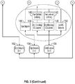
- FIGS. 2 and 3 depict a power system 100 of an aircraft 10 that includes the gas turbine engine 20 of FIG. 1 (also referred to generally as an aircraft engine) according to an embodiment.
- the power system 100 can include a hybrid energy storage system 102 with at least two energy storage subsystems 103 ( FIG. 4 ) each having a different power-energy density, power draw characteristics and/or dissimilar configuration/architecture to meet various types of power demands and fault protection with backup power sources.
- the at least two energy storage subsystems 103 include a super/ultra-capacitor 104 and a battery system 106.
- the hybrid energy storage system 102 may be sized to store energy to support transient bursts of the gas turbine engine 20 for a power assist during a snap acceleration or power shedding during a snap deceleration. Using only the battery system 106 for a wide range of acceleration and deceleration conditions may result in oversizing battery capacity with corresponding additional weight carried to meet potential transient demands.
- the super/ultra-capacitor 104 provides a lower storage capacity than the battery system 106 but has a higher charge/discharge rate as compared to the battery system 106.
- the super/ultra-capacitor 104 can be comprised of one or more electrochemical double layer capacitors (EDLCs) or electrochemical capacitors that have a high energy density when compared to common capacitors, e.g., several orders of magnitude greater than a high-capacity electrolytic capacitor.
- EDLCs electrochemical double layer capacitors
- the super/ultra-capacitor 104 can have higher energy efficiency due to a lower internal resistance than the battery system 106.
- the super/ultra-capacitor 104 can be operatively coupled to the battery system 106 through a direct current (DC)-to-DC converter 108.
- DC direct current
- the DC-to-DC converter 108 can convert a voltage level of the battery system 106 to match a voltage level of the super/ultra-capacitor 104 to support charging of the super/ultra-capacitor 104 by the battery system 106. In alternate embodiments, the DC-to-DC converter 108 can be omitted where regulation between the super/ultra-capacitor 104 and the battery system 106 is not needed.
- the battery system 106 is an example of a first energy storage subsystem, and the super/ultra-capacitor 104 is an example of a second energy storage system.
- the hybrid energy storage system 102 can also include a third energy storage system that includes an isolated battery pack 107 accessible by the power management controller 190 based on determining that a mode of operation of the aircraft 10 is a ground-based mode of operation or an emergency power mode of operation.
- the emergency power mode can use the isolated battery pack 109 to provide power through a DC-to-DC converter 109 to other elements of the power system 100, for instance, in place of a ram-air turbine.
- an electric motor 110 and a first generator 111 are operably coupled to at least one shaft 112 of an aircraft engine, such as the inner shaft 40 of low speed spool 30 or the outer shaft 50 of high speed spool 32 of the gas turbine engine 20 of FIG. 1 , which may also be referred to as a primary power unit.
- the hybrid energy storage system 102 is operably coupled to a bidirectional power converter 114 (e.g., a bidirectional DC-to-DC converter) which is operably coupled to a motor controller 115 (also referred to as power conditioning electronics 115) and a first generator controller 116 (also referred to as power conditioning electronics 116).
- the motor controller 115 interfaces with the electric motor 110, and the first generator controller 116 interfaces with the first generator 111.
- the bidirectional power converter 114 also interfaces with the power management controller 190, for instance, through a hybrid energy storage system management system 117 of the bidirectional power converter 114. Further, the bidirectional power converter 114 can interface with a second generator controller 130 (also referred to as power conditioning electronics 130) of a second generator 132 of a secondary power unit 134.
- the secondary power unit 134 can be a heat engine or any type of power generating device operable to drive rotation of the second generator 132.
- a plurality of aircraft electrical subsystems 140 is operably coupled to the bidirectional power converter 114, and the power management controller 190 is configured to extract power from or provide power to the aircraft electrical subsystems 140 through subsystem controls 142 (also referred to as power conditioning electronics 142).
- the aircraft electrical subsystems 140 can include one or more of an engine subsystem 144, an aircraft low-voltage DC subsystem 146, an aircraft high-voltage DC subsystem 148, and an aircraft AC subsystem 150.
- the power management controller 190 is operable to monitor a state of charge of the hybrid energy storage system 102, a power request of an engine subsystem control 152 of the secondary power unit 134, an engine subsystem control 154 of the engine subsystem 144, an aircraft subsystem control 156, and the one or more controllers 115, 116, 130 of the electric motor 115, the first generator 111, and the second generator 132.
- the bidirectional power converter 114 can perform any voltage conversions needed between elements of the power system 100. Although only one bidirectional power converter 114 is depicted, it will be understood that multiple bidirectional power converters can be incorporated in the power system 100 and that reference to the bidirectional power converter 114 can include one or more bidirectional power converters within the power system 100.
- the power conditioning electronics 115, 116, 130, 142 can include inverter/motor drive circuitry that applies known motor control techniques to control the speed and/or torque produced by one or more of the electric motor 110, first generator 111, and second generator 132.
- electric power from the hybrid energy storage system 102 is provided through the bidirectional power converter 114 and the power conditioning electronics 115 to drive the electric motor 110 in a motor mode to supplement rotation of the engine shaft 112 as opposed by an engine load.
- the engine load on the engine shaft 112 can vary depending upon a flight regime and accessory loading from generators, environmental control systems, engine bleeds, and other known loading factors.
- the first generator 111 can be used to increase the engine load on the engine shaft 112, with resulting current passed through the bidirectional power converter 114 for storage in the hybrid energy storage system 102 or used elsewhere within the power system 100.
- the hybrid energy storage system management system 117 of the bidirectional power converter 114 can be operably coupled to a battery management system 119 of the DC-to-DC converter 108 and/or to a battery management system 121 to control and manage the battery system 106 and isolated battery pack 107 respectively.
- the battery management systems 119, 121 can provide local status information such as a state of charge or health of the battery system 106 and isolated battery pack 107. Isolation can prevent the isolated battery pack 107 from being drained in unintended modes of operation.
- the power management controller 190 can provide a means for controlling one or more electric power flows of the hybrid energy storage system 102 to/from the one or more electric motor 110, first generator 111, second generator 132, and aircraft electrical subsystems 140 based on a modeled electric power demand of an engine load of the aircraft engine that may be at a current time step or predicted at one or more future time steps, for example.
- the power management controller 190 (also referred to as controller 190) is operable to detect one or more conditions of the super/ultra-capacitor 104 and the battery system 106 and configure the one or more electric power flows between the hybrid energy storage system 102 and other elements of the power system 100.
- Detectable conditions can include a current charge level, a remaining storage capacity, health/fault status, and other such information. Further, the conditions may be derived based on environmental factors, previous usage data or aging effects. For example, if a temperature of the battery system 106 impacts the storage capacity and/or charge/discharge rate, then such information can be determined in assessing the condition of the battery system 106.
- the power management controller 190 can interface with and control multiple elements of the power system 100 and the gas turbine engine 20, such as switches, current sensors, voltage sensors, temperature sensors, communication buses, and the like.
- the power management controller 190 includes a memory system 192 to store instructions that are executed by a processing system 194 of the power management controller 190.
- the executable instructions may be stored or organized in any manner and at any level of abstraction, such as in connection with a controlling and/or monitoring operation of the power system 100 and/or the gas turbine engine 20.
- the processing system 194 can include one or more processors that can be any type of central processing unit (CPU), including a microprocessor, a digital signal processor (DSP), a microcontroller, an application specific integrated circuit (ASIC), a field programmable gate array (FPGA), or the like.
- the memory system 192 may include random access memory (RAM), read only memory (ROM), or other electronic, optical, magnetic, or any other computer readable medium onto which is stored data and control algorithms in a non-transitory form.
- RAM random access memory
- ROM read only memory
- Other controllers of FIGS. 2 and 3 can include similar elements.
- Various electric power flows 120, 122, 124 can be bidirectionally controlled to shift energy between elements of the power system 100. Selection and timing for engaging the various electric power flows 120-124 can be controlled by the power management controller 190.
- the power management controller 190 may be implemented as a predictive controller or other model-based control as further described in reference to FIG. 4 .
- a control system 200 of the power system 100 can include the power management controller 190 includes a model-based control, such as a model predictive control, operable to output one or more electric power flow control signals.
- Predictive power management can include dynamically reading status of each of the power source and predicting what loads will be required to proactively optimize power flows, such as closing contactors predictively to enable an optimal power flow with reduced delays.
- a delay between requesting power and delivering power can exist where contactors or other components have a switching or settling time delay.
- the power management controller 190 can include models with maps, equations, and the like that relate voltage, current, electrical power, and state-of-charge, for example.
- the system-level control algorithm integrates the models associated with each subsystem and includes their respective constraints.
- T motor F motor (I phase , V, N shaft )
- the function can be an equation, a look-up table, a map that relates the currents in all the motor phases, the voltage, and the shaft rotational speed to generated motor torque.
- constraints are defined and included in the overall control problem definition. These are related to motor torque, T motor, min ⁇ T motor ⁇ T motor , max, shaft angular speed, N shaft, min ⁇ N shaft ⁇ N shaft, max .
- the objective in controlling the hybrid energy storage system is to meet the requested shaft torque; a cost function that penalizes the errors between the motor torque T Motor and the requested shaft torque T Shaft,Req can be used ⁇ [T Motor (t)- T Shaft,Req (t)]dt, where the integral is calculated at each time step over a receding horizon [0, Dt], assuming that the requested motor torque is known over this time interval.
- the motor torque request can be set based on various external conditions such as: shaft speed and acceleration; overall system operating condition.
- the optimization problem including the defined cost function, system dynamics and constraints has as control inputs the current supplied by the battery system and modes of operation (charging, discharging) for each subsystem, and it is therefore a mixed-integer programming problem which can be solved numerically by using customized solvers. Additionally, monitoring input power and integrating over time to obtain energy consumption provides a high-level monitor on battery or super/ultra-capacitor capacity consumed as a model input for continuing power draw or charging functions.
- Elements such as the super/ultra-capacitor 104 can be modeled using observed conditions and a physics-based model that incorporates sizing parameters, for example, to determine predicted charge time, discharge time, capacity, available charge, and other such information.
- the battery system 106 and/or isolated battery pack 107 of FIG. 2 can be modeled using observed conditions and a physics-based model that incorporates sizing parameters, for example, to determine predicted charge time, discharge time, capacity, available charge, and other such information.
- An engine system model may model an engine load on the engine shaft 112 presently and at one or more future time steps.
- the engine system model may receive engine parameters from an engine control or flight computer system (not depicted) that assist with load predictions.
- the load predictions can include flight regime (e.g., idle, takeoff, climb, cruise, decent, thrust reverse, etc.) along with demands due to known loads and operating status of other propulsion system elements (e.g., operational status of other engines on the aircraft).
- the power flow control signals can control switching states and times of elements within the power system 100.
- the model-based control receives information about current engine loading and an engine load over one or more future time steps from the engine system model.
- the model-based control can access the super/ultra-capacitor model and the battery system model with corresponding power constraints to determine power profiles for the super/ultra-capacitor 104 and the battery system 106 and/or isolated battery pack 107 such that a power demand is met.
- Constraints can include healthy values, rates, and/or ranges for associated parameters. For instance, if a power demand exceeds the modeled capability of the battery system 106, then electric power can be provided by the super/ultra-capacitor 104.
- the power management controller 190 can perform recharging from the battery system 106.
- the power demand can be initially met by the battery system 106, but upon exceeding the power demand provided by battery system 106, additional power can be provided by the super/ultra-capacitor 104 via the second electric power flow 122.
- time-based analysis selects either or both of the super/ultra-capacitor 104 and the battery system 106, for instance, by determining current demand and charge/discharge rates and capacity.
- Equations, limits and constraints examples include the follow: min Wf , T m 1 , T m 2 , T g 1 , T g 2 , VV LPC , VV HPC ⁇ t 0 t 0 + T w 1 ⁇ Thrust Ref ⁇ Thrust HEP 2 + w 2 ⁇ W f + w 3 ⁇ Life Index + w 4 ⁇ PR HPC , Ref ⁇ PR HPC 2
- T f can be a fuel flow.
- VV can be variable vane values (e.g., vane positions for low pressure compressor (LPC) and high pressure compressor (HPC)).
- Constraints can include power (P), pressure ratio (PR), state of charge (SOC), temperatures, motor parameters (m1, m2), component life, weights (w1, w2, w3, w4), and other such factors.
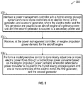
- FIG. 5 is a flow chart illustrating a method 300 of controlling a power system 100 of an aircraft 10 in accordance with an embodiment.
- the method 300 of FIG. 5 is described in reference to FIGS. 1-5 and may be performed with an alternate order and include additional steps.
- the method 300 can be performed, for example, by the power system 100 of FIGS. 2-3 or an alternate configuration.
- power management controller 190 can interface with a hybrid energy storage system 102 and one or more controllers 115, 116, 130 of an electric motor 110, a first generator 111, and a second generator 132, where the hybrid energy storage system 102 includes at least two energy storage subsystems 103 each having a different power-energy density, and the electric motor 110 and the first generator 111 are coupled to an aircraft engine 20 of a primary power unit and the second generator 132 is coupled to a secondary power unit 134.
- power management controller 190 can receive an engine propulsion power demand for the aircraft engine 20.
- the power management controller 190 can perform a model predictive control to dynamically adjust one or more electric power flows 120-124 through a bidirectional power converter 114 based on the engine propulsion power demand, where the bidirectional power converter 114 is coupled to the hybrid energy storage system 102 and one or more controllers 115, 116, 130 of the electric motor 110, the first generator 111, and the second generator 132.
- the power management controller 190 can detect one or more conditions of the at least two energy storage subsystems 103, such as the super/ultra-capacitor 104 and the battery system 106 and configure the one or more electric power flows 120-124 based on the one or more conditions of the super/ultra-capacitor 104 and the battery system 106.
- the power management controller 190 can configure at least one of the one or more electric power flows 120-124 from a first energy storage subsystem of the at least two energy storage subsystems 103 to charge a second energy storage subsystem of the at least two energy storage subsystem 103, such as from the battery system 106 through a DC-to-DC converter 108 to charge the super/ultra-capacitor 104.
- the hybrid energy storage system 102 can include a third energy storage system having an isolated battery pack 107 accessible by the power management controller 190 based on determining that a mode of operation of the aircraft is a ground-based mode of operation or an emergency power mode of operation. Limiting availability to access power of the isolated battery pack 107 to certain operating conditions ensures that power is available after mission completion (e.g., e-taxi on ground) or if needed in an emergency where other electrical power is lost.
- a plurality of aircraft electrical subsystems 140 can be operably coupled to the bidirectional power converter 114, and the power management controller 190 can be configured to extract power from or provide power to the aircraft electrical subsystems 140.
- the aircraft electrical subsystems 140 can include one or more of an engine subsystem 144, an aircraft low-voltage DC subsystem 146, an aircraft high-voltage DC subsystem 148, and an aircraft AC subsystem 150.
- model predictive control can be based on one or more aircraft subsystem power demands of the aircraft electrical subsystems 140.
- the power management controller 190 can be operable to monitor a state of charge of the hybrid energy storage system 102, a power request of an engine subsystem control 154 of the engine subsystem 144, an aircraft subsystem control 154, and the one or more controllers 115, 116, 130 of the electric motor 110, the first generator 111, and the second generator 132.
- the power management controller 190 is operable to determine a current status and constraints from the engine subsystem control 154, the aircraft subsystem control 156, and the one or more controllers 115, 116, 130 of the electric motor 110, the first generator 111, and the second generator 132.
- the power management controller 190 can receive the engine propulsion power demand and data from a plurality of engine sensors and determine a plurality of desired values for electrical power levels.
- the power management controller 190 can communicate the desired values for electrical power levels to the engine subsystem control 154, the aircraft subsystem control 156, and the one or more controllers of the electric motor, the first generator, and the second generator.
- the model predictive control 190 can determine the electrical power levels by computing a plurality of future step values using a plurality of dynamic equations that model a plurality of subsystems, the current status and constraints, and an objective function based on an error between a requested and an allocation power level or thrust.
- the power management controller 190 is operable to predictively switch horsepower extractions from the gas turbine engine 20 to source power from the hybrid energy storage system 102 instead of the gas turbine engine 20.
- Power transfers may be achieved by one or more automatic bus transfers (ABT). Further, if additional bus power is needed, an uninterruptable power supply (UPS) may be used to enhance electric bus stiffness.
- ABT automatic bus transfers
- UPS uninterruptable power supply
Landscapes
- Engineering & Computer Science (AREA)
- Power Engineering (AREA)
- Charge And Discharge Circuits For Batteries Or The Like (AREA)
Abstract
Description
- Exemplary embodiments pertain to aircraft systems, and more particularly to systems and methods of controlling a hybrid electric power distribution for an aircraft.
- Aircraft, such as those utilized by commercial airlines, typically include two or more gas turbine engines. The engines generate thrust, propelling the aircraft forward and allowing operation of the aircraft. A typical engine utilized in this configuration includes a fan forward of a turbine engine core, with the turbine engine core driving the rotation of the fan either via a direct drive system or a geared connection. Some aircraft propulsion systems also include one or more electric motors and/or generators to provide a supplemental power source under certain aircraft operating conditions.
- Disclosed is a power system of an aircraft, where the power system includes a hybrid energy storage system with at least two energy storage subsystems each having a different power-energy density, power draw characteristics and/or dissimilar configuration. The power system also includes a primary power unit including an aircraft engine coupled to an electric motor and a first generator, and a secondary power unit coupled to a second generator. The power system also includes a bidirectional power converter coupled to the hybrid energy storage system and one or more controllers of the electric motor, the first generator, and the second generator. A power management controller is configured to interface with the hybrid energy storage system and the one or more controllers of the electric motor, the first generator, and the second generator and perform a model predictive control to dynamically adjust one or more electric power flows through the bidirectional power converter based on an engine propulsion power demand of the aircraft engine.
- In addition to one or more of the features described above or below, or as an alternative, further embodiments may include where the power management controller is operable to detect one or more conditions of the at least two energy storage subsystems and configure the one or more electric power flows.
- In addition to one or more of the features described above or below, or as an alternative, further embodiments may include where the power management controller is operable to configure at least one of the one or more electric power flows from a first energy storage subsystem of the at least two energy storage subsystems to charge a second energy storage subsystem of the at least two energy storage subsystems.
- In addition to one or more of the features described above or below, or as an alternative, further embodiments may include where the first energy storage subsystem includes a battery system and a battery management system, the second energy storage subsystem includes a super/ultra-capacitor, and the bidirectional power converter is operably coupled to the super/ultra-capacitor and the battery management system.
- In addition to one or more of the features described above or below, or as an alternative, further embodiments may include where the hybrid energy storage system includes a third energy storage system with an isolated battery pack accessible by the power management controller based on determining that a mode of operation of the aircraft is a ground-based mode of operation or an emergency power mode of operation.
- In addition to one or more of the features described above or below, or as an alternative, further embodiments may include where a plurality of aircraft electrical subsystems is operably coupled to the bidirectional power converter and the power management controller is configured to extract power from or provide power to the aircraft electrical subsystems, and the model predictive control can be further based on one or more aircraft subsystem power demands.
- In addition to one or more of the features described above or below, or as an alternative, further embodiments may include where the aircraft electrical subsystems include one or more of an engine subsystem, an aircraft low-voltage DC subsystem, an aircraft high-voltage DC subsystem, and an aircraft AC subsystem.
- In addition to one or more of the features described above or below, or as an alternative, further embodiments may include where the power management controller is operable to monitor a state of charge of the hybrid energy storage system, a power request of an engine subsystem control of the engine subsystem, an aircraft subsystem control, and the one or more controllers of the electric motor, the first generator, and the second generator.
- In addition to one or more of the features described above or below, or as an alternative, further embodiments may include where the power management controller is operable to determine a current status and constraints from the engine subsystem control, the aircraft subsystem control, and the one or more controllers of the electric motor, the first generator, and the second generator. The engine propulsion power demand and data from a plurality of engine sensors can be received. A plurality of desired values can be determined for electrical power levels. The desired values for electrical power levels can be communicated to the engine subsystem control, the aircraft subsystem control, and the one or more controllers of the electric motor, the first generator, and the second generator.
- In addition to one or more of the features described above or below, or as an alternative, further embodiments may include where the model predictive control determines the electrical power levels by computing a plurality of future step values using a plurality of dynamic equations that model a plurality of subsystems, the current status and constraints, and an objective function based on an error between a requested and an allocation power level or thrust.
- Also disclosed is a method that includes interfacing a power management controller with a hybrid energy storage system and one or more controllers of an electric motor, a first generator, and a second generator, where the hybrid energy storage system includes at least two energy storage subsystems each having a different power-energy density and power draw characteristics, and the electric motor and the first generator are coupled to an aircraft engine of a primary power unit and the second generator is coupled to a secondary power unit. The power management controller receives an engine propulsion power demand for the aircraft engine. A model predictive control is performed to dynamically adjust one or more electric power flows through a bidirectional power converter based on the engine propulsion power demand, where the bidirectional power converter is coupled to the hybrid energy storage system and one or more controllers of the electric motor, the first generator, and the second generator.
- In addition to one or more of the features described above or below, or as an alternative, further embodiments may include detecting one or more conditions of the at least two energy storage subsystems, and configuring the one or more electric power flows based on the one or more conditions of the at least two energy storage subsystems.
- In addition to one or more of the features described above or below, or as an alternative, further embodiments may include configuring at least one of the one or more electric power flows from a first energy storage subsystem of the at least two energy storage subsystems to charge a second energy storage subsystem of the at least two energy storage subsystems.
- In addition to one or more of the features described above or below, or as an alternative, further embodiments may include determining a current status and constraints from the engine subsystem control, the aircraft subsystem control, and the one or more controllers of the electric motor, the first generator, and the second generator; receiving the engine propulsion power demand and data from a plurality of engine sensors; determining a plurality of desired values for electrical power levels; and communicating the desired values for electrical power levels to the engine subsystem control, the aircraft subsystem control, and the one or more controllers of the electric motor, the first generator, and the second generator.
- In addition to one or more of the features described above or below, or as an alternative, further embodiments may include determining the electrical power levels by computing a plurality of future step values using a plurality of dynamic equations that model a plurality of subsystems, the current status and constraints, historical energy consumption, and an objective function based on an error between a requested and an allocation power level or thrust.
- A technical effect of systems and methods is achieved by providing hybrid electric power distribution for an aircraft as described herein.
- The following descriptions should not be considered limiting in any way. With reference to the accompanying drawings, like elements are numbered alike:
-
FIG. 1 is a schematic illustration of a gas turbine engine in accordance with an embodiment of the disclosure; -
FIG. 2 is a schematic illustration of a power system in accordance with an embodiment of the disclosure; -
FIG. 3 is a schematic illustration of the power system ofFIG. 2 in greater detail in accordance with an embodiment of the disclosure; -
FIG. 4 is a schematic illustration of a control system in accordance with an embodiment of the disclosure; and -
FIG. 5 is a flow chart illustrating a method in accordance with an embodiment of the disclosure. - A detailed description of one or more embodiments of the disclosed apparatus and method are presented herein by way of exemplification and not limitation with reference to the Figures.
-
FIG. 1 schematically illustrates agas turbine engine 20. Thegas turbine engine 20 is disclosed herein as a two-spool turbofan that generally incorporates afan section 22, acompressor section 24, acombustor section 26 and aturbine section 28. Thefan section 22 drives air along a bypass flow path B in a bypass duct, while thecompressor section 24 drives air along a core flow path C for compression and communication into thecombustor section 26 then expansion through theturbine section 28. Although depicted as a two-spool turbofan gas turbine engine in the disclosed non-limiting embodiment, it should be understood that the concepts described herein are not limited to use with two-spool turbofans as the teachings may be applied to other types of turbine engines including three-spool architectures. - The
exemplary engine 20 generally includes alow speed spool 30 and ahigh speed spool 32 mounted for rotation about an engine central longitudinal axis A relative to an enginestatic structure 36 viaseveral bearing systems 38. It should be understood thatvarious bearing systems 38 at various locations may alternatively or additionally be provided, and the location ofbearing systems 38 may be varied as appropriate to the application. - The
low speed spool 30 generally includes aninner shaft 40 that interconnects afan 42, alow pressure compressor 44 and alow pressure turbine 46. Theinner shaft 40 is connected to thefan 42 through a speed change mechanism, which in exemplarygas turbine engine 20 is illustrated as a gearedarchitecture 48 to drive thefan 42 at a lower speed than thelow speed spool 30. Thehigh speed spool 32 includes anouter shaft 50 that interconnects ahigh pressure compressor 52 andhigh pressure turbine 54. Acombustor 56 is arranged inexemplary gas turbine 20 between thehigh pressure compressor 52 and thehigh pressure turbine 54. An enginestatic structure 36 is arranged generally between thehigh pressure turbine 54 and thelow pressure turbine 46. The enginestatic structure 36 further supports bearingsystems 38 in theturbine section 28. Theinner shaft 40 and theouter shaft 50 are concentric and rotate viabearing systems 38 about the engine central longitudinal axis A which is collinear with their longitudinal axes. - The core airflow is compressed by the
low pressure compressor 44 then thehigh pressure compressor 52, mixed and burned with fuel in thecombustor 56, then expanded over thehigh pressure turbine 54 andlow pressure turbine 46. Theturbines low speed spool 30 andhigh speed spool 32 in response to the expansion. It will be appreciated that each of the positions of thefan section 22,compressor section 24,combustor section 26,turbine section 28, and fandrive gear system 48 may be varied. For example,gear system 48 may be located aft ofcombustor section 26 or even aft ofturbine section 28, andfan section 22 may be positioned forward or aft of the location ofgear system 48. - The
engine 20 in one example is a high-bypass geared aircraft engine. In a further example, theengine 20 bypass ratio is greater than about six (6), with an example embodiment being greater than about ten (10), the gearedarchitecture 48 is an epicyclic gear train, such as a planetary gear system or other gear system, with a gear reduction ratio of greater than about 2.3 and thelow pressure turbine 46 has a pressure ratio that is greater than about five. In one disclosed embodiment, theengine 20 bypass ratio is greater than about ten (10:1), the fan diameter is significantly larger than that of thelow pressure compressor 44, and thelow pressure turbine 46 has a pressure ratio that is greater than about five 5:1.Low pressure turbine 46 pressure ratio is pressure measured prior to inlet oflow pressure turbine 46 as related to the pressure at the outlet of thelow pressure turbine 46 prior to an exhaust nozzle. The gearedarchitecture 48 may be an epicycle gear train, such as a planetary gear system or other gear system, with a gear reduction ratio of greater than about 2.3:1. It should be understood, however, that the above parameters are only exemplary of one embodiment of a geared architecture engine and that the present disclosure is applicable to other gas turbine engines including direct drive turbofans. - A significant amount of thrust is provided by the bypass flow B due to the high bypass ratio. The
fan section 22 of theengine 20 is designed for a particular flight condition--typically cruise at about 0.8 Mach and about 35,000 feet (10,668 meters). The flight condition of 0.8 Mach and 35,000 ft (10,668 meters), with the engine at its best fuel consumption--also known as "bucket cruise Thrust Specific Fuel Consumption ('TSFC')"--is the industry standard parameter of lbm of fuel being burned divided by lbf of thrust the engine produces at that minimum point. "Low fan pressure ratio" is the pressure ratio across the fan blade alone, without a Fan Exit Guide Vane ("FEGV") system. The low fan pressure ratio as disclosed herein according to one non-limiting embodiment is less than about 1.45. "Low corrected fan tip speed" is the actual fan tip speed in ft/sec divided by an industry standard temperature correction of [(Tram °R)/(518.7 °R)]0.5. The "Low corrected fan tip speed" as disclosed herein according to one non-limiting embodiment is less than about 1150 ft/second (350.5 m/sec). -
FIGS. 2 and3 depict apower system 100 of anaircraft 10 that includes thegas turbine engine 20 ofFIG. 1 (also referred to generally as an aircraft engine) according to an embodiment. Thepower system 100 can include a hybridenergy storage system 102 with at least two energy storage subsystems 103 (FIG. 4 ) each having a different power-energy density, power draw characteristics and/or dissimilar configuration/architecture to meet various types of power demands and fault protection with backup power sources. In the example ofFIG. 3 , the at least twoenergy storage subsystems 103 include a super/ultra-capacitor 104 and abattery system 106. The hybridenergy storage system 102 may be sized to store energy to support transient bursts of thegas turbine engine 20 for a power assist during a snap acceleration or power shedding during a snap deceleration. Using only thebattery system 106 for a wide range of acceleration and deceleration conditions may result in oversizing battery capacity with corresponding additional weight carried to meet potential transient demands. The super/ultra-capacitor 104 provides a lower storage capacity than thebattery system 106 but has a higher charge/discharge rate as compared to thebattery system 106. The super/ultra-capacitor 104 can be comprised of one or more electrochemical double layer capacitors (EDLCs) or electrochemical capacitors that have a high energy density when compared to common capacitors, e.g., several orders of magnitude greater than a high-capacity electrolytic capacitor. The super/ultra-capacitor 104 can have higher energy efficiency due to a lower internal resistance than thebattery system 106. The super/ultra-capacitor 104 can be operatively coupled to thebattery system 106 through a direct current (DC)-to-DC converter 108. The DC-to-DC converter 108 can convert a voltage level of thebattery system 106 to match a voltage level of the super/ultra-capacitor 104 to support charging of the super/ultra-capacitor 104 by thebattery system 106. In alternate embodiments, the DC-to-DC converter 108 can be omitted where regulation between the super/ultra-capacitor 104 and thebattery system 106 is not needed. - The
battery system 106 is an example of a first energy storage subsystem, and the super/ultra-capacitor 104 is an example of a second energy storage system. The hybridenergy storage system 102 can also include a third energy storage system that includes anisolated battery pack 107 accessible by thepower management controller 190 based on determining that a mode of operation of theaircraft 10 is a ground-based mode of operation or an emergency power mode of operation. The emergency power mode can use theisolated battery pack 109 to provide power through a DC-to-DC converter 109 to other elements of thepower system 100, for instance, in place of a ram-air turbine. - In embodiments, an
electric motor 110 and afirst generator 111 are operably coupled to at least oneshaft 112 of an aircraft engine, such as theinner shaft 40 oflow speed spool 30 or theouter shaft 50 ofhigh speed spool 32 of thegas turbine engine 20 ofFIG. 1 , which may also be referred to as a primary power unit. In the example ofFIGS. 2 and3 , the hybridenergy storage system 102 is operably coupled to a bidirectional power converter 114 (e.g., a bidirectional DC-to-DC converter) which is operably coupled to a motor controller 115 (also referred to as power conditioning electronics 115) and a first generator controller 116 (also referred to as power conditioning electronics 116). Themotor controller 115 interfaces with theelectric motor 110, and thefirst generator controller 116 interfaces with thefirst generator 111. Thebidirectional power converter 114 also interfaces with thepower management controller 190, for instance, through a hybrid energy storagesystem management system 117 of thebidirectional power converter 114. Further, thebidirectional power converter 114 can interface with a second generator controller 130 (also referred to as power conditioning electronics 130) of asecond generator 132 of asecondary power unit 134. Thesecondary power unit 134 can be a heat engine or any type of power generating device operable to drive rotation of thesecond generator 132. A plurality of aircraftelectrical subsystems 140 is operably coupled to thebidirectional power converter 114, and thepower management controller 190 is configured to extract power from or provide power to the aircraftelectrical subsystems 140 through subsystem controls 142 (also referred to as power conditioning electronics 142). The aircraftelectrical subsystems 140 can include one or more of anengine subsystem 144, an aircraft low-voltage DC subsystem 146, an aircraft high-voltage DC subsystem 148, and anaircraft AC subsystem 150. Thepower management controller 190 is operable to monitor a state of charge of the hybridenergy storage system 102, a power request of anengine subsystem control 152 of thesecondary power unit 134, anengine subsystem control 154 of theengine subsystem 144, anaircraft subsystem control 156, and the one ormore controllers electric motor 115, thefirst generator 111, and thesecond generator 132. - The
bidirectional power converter 114 can perform any voltage conversions needed between elements of thepower system 100. Although only onebidirectional power converter 114 is depicted, it will be understood that multiple bidirectional power converters can be incorporated in thepower system 100 and that reference to thebidirectional power converter 114 can include one or more bidirectional power converters within thepower system 100. Thepower conditioning electronics electric motor 110,first generator 111, andsecond generator 132. For example, during a snap acceleration, electric power from the hybridenergy storage system 102 is provided through thebidirectional power converter 114 and thepower conditioning electronics 115 to drive theelectric motor 110 in a motor mode to supplement rotation of theengine shaft 112 as opposed by an engine load. The engine load on theengine shaft 112 can vary depending upon a flight regime and accessory loading from generators, environmental control systems, engine bleeds, and other known loading factors. During a snap deceleration, thefirst generator 111 can be used to increase the engine load on theengine shaft 112, with resulting current passed through thebidirectional power converter 114 for storage in the hybridenergy storage system 102 or used elsewhere within thepower system 100. The hybrid energy storagesystem management system 117 of thebidirectional power converter 114 can be operably coupled to abattery management system 119 of the DC-to-DC converter 108 and/or to abattery management system 121 to control and manage thebattery system 106 andisolated battery pack 107 respectively. Thebattery management systems battery system 106 andisolated battery pack 107. Isolation can prevent theisolated battery pack 107 from being drained in unintended modes of operation. - In embodiments, the
power management controller 190 can provide a means for controlling one or more electric power flows of the hybridenergy storage system 102 to/from the one or moreelectric motor 110,first generator 111,second generator 132, and aircraftelectrical subsystems 140 based on a modeled electric power demand of an engine load of the aircraft engine that may be at a current time step or predicted at one or more future time steps, for example. The power management controller 190 (also referred to as controller 190) is operable to detect one or more conditions of the super/ultra-capacitor 104 and thebattery system 106 and configure the one or more electric power flows between the hybridenergy storage system 102 and other elements of thepower system 100. Detectable conditions can include a current charge level, a remaining storage capacity, health/fault status, and other such information. Further, the conditions may be derived based on environmental factors, previous usage data or aging effects. For example, if a temperature of thebattery system 106 impacts the storage capacity and/or charge/discharge rate, then such information can be determined in assessing the condition of thebattery system 106. - The
power management controller 190 can interface with and control multiple elements of thepower system 100 and thegas turbine engine 20, such as switches, current sensors, voltage sensors, temperature sensors, communication buses, and the like. In an embodiment, thepower management controller 190 includes amemory system 192 to store instructions that are executed by aprocessing system 194 of thepower management controller 190. The executable instructions may be stored or organized in any manner and at any level of abstraction, such as in connection with a controlling and/or monitoring operation of thepower system 100 and/or thegas turbine engine 20. Theprocessing system 194 can include one or more processors that can be any type of central processing unit (CPU), including a microprocessor, a digital signal processor (DSP), a microcontroller, an application specific integrated circuit (ASIC), a field programmable gate array (FPGA), or the like. Also, in embodiments, thememory system 192 may include random access memory (RAM), read only memory (ROM), or other electronic, optical, magnetic, or any other computer readable medium onto which is stored data and control algorithms in a non-transitory form. Other controllers ofFIGS. 2 and3 can include similar elements. - Various electric power flows 120, 122, 124 can be bidirectionally controlled to shift energy between elements of the
power system 100. Selection and timing for engaging the various electric power flows 120-124 can be controlled by thepower management controller 190. As one example, thepower management controller 190 may be implemented as a predictive controller or other model-based control as further described in reference toFIG. 4 . - In the example of
FIG. 4 with continued reference toFIGS. 1-3 , acontrol system 200 of thepower system 100 can include thepower management controller 190 includes a model-based control, such as a model predictive control, operable to output one or more electric power flow control signals. Predictive power management can include dynamically reading status of each of the power source and predicting what loads will be required to proactively optimize power flows, such as closing contactors predictively to enable an optimal power flow with reduced delays. As an example, a delay between requesting power and delivering power can exist where contactors or other components have a switching or settling time delay. By predictively closing contactors or commanding other such state changes prior to a needed delivery of power, system responsiveness can be enhanced. Thepower management controller 190 can include models with maps, equations, and the like that relate voltage, current, electrical power, and state-of-charge, for example. The system-level control algorithm integrates the models associated with each subsystem and includes their respective constraints. The electric motor(s) can be modeled as Tmotor = Fmotor(Iphase, V, Nshaft) where the function can be an equation, a look-up table, a map that relates the currents in all the motor phases, the voltage, and the shaft rotational speed to generated motor torque. Several constraints are defined and included in the overall control problem definition. These are related to motor torque, Tmotor, min ≤Tmotor≤Tmotor, max, shaft angular speed, Nshaft, min ≤Nshaft≤Nshaft, max. Similarly, a model Fgenerator(Iphase, V, Nshaft) and constraints Tgenerator, min ≤generator≤Tgenerator, max are defined for the generator(s). Additional parameters can also be incorporated in motor torque modeling, such as loads, back-electromagnetic field effects, and other such electrical and mechanical parameters. The phase currents that control the motor torque can be generated by a motor drive/inverter and related to the direct current through another set of equations, Iphase = Finv(V, IDC, Nshaft), where Finv could be a set of equations, maps or look-up tables. The direct current, IDC, depends upon the current provided by the ultra-capacitor or supercapacitor IDC, UC and/or the current supplied by the batteries, IDC, Bat, and needs to be bounded IDC, min ≤IDC≤IDC, max (with the positive upper bound active during discharging, and the negative, lower bound active during charging). Each of the current depends on the state-of-charge and state-of-health of the ultra-capacitor and battery system, IDC,UC=FI,UC(SOCUC, V, mode) and LDC,Bat=FI,Bat(SOCBat, V, mode). The state-of-charge and state-of-health are dynamical states that are interrelated and depend on the current supplied by each storage subsystem. Because they have different dynamics depending on whether they are charging or discharging the functions that relate current, SOC, SOH are specific to each mode of operation. In order to ensure that the batteries continue to operate correctly for many charging-discharging cycles, the two key parameters are bounded: SOCBat,min≤SOCBat≤SOCBat,max and SOHBat,min≤SOHBat. All the models mentioned above and their associated constraints are lumped into an integrated, dynamical system-level model dXSys = Fsys(XSys, mode) and constraints XSys, min≤XSys≤XSys,max. The objective in controlling the hybrid energy storage system is to meet the requested shaft torque; a cost function that penalizes the errors between the motor torque TMotor and the requested shaft torque TShaft,Req can be used ∫[TMotor(t)- TShaft,Req(t)]dt, where the integral is calculated at each time step over a receding horizon [0, Dt], assuming that the requested motor torque is known over this time interval. The motor torque request can be set based on various external conditions such as: shaft speed and acceleration; overall system operating condition. The optimization problem including the defined cost function, system dynamics and constraints has as control inputs the current supplied by the battery system and modes of operation (charging, discharging) for each subsystem, and it is therefore a mixed-integer programming problem which can be solved numerically by using customized solvers. Additionally, monitoring input power and integrating over time to obtain energy consumption provides a high-level monitor on battery or super/ultra-capacitor capacity consumed as a model input for continuing power draw or charging functions. - Elements such as the super/ultra-capacitor 104 can be modeled using observed conditions and a physics-based model that incorporates sizing parameters, for example, to determine predicted charge time, discharge time, capacity, available charge, and other such information. Similarly, the
battery system 106 and/orisolated battery pack 107 ofFIG. 2 can be modeled using observed conditions and a physics-based model that incorporates sizing parameters, for example, to determine predicted charge time, discharge time, capacity, available charge, and other such information. An engine system model may model an engine load on theengine shaft 112 presently and at one or more future time steps. The engine system model may receive engine parameters from an engine control or flight computer system (not depicted) that assist with load predictions. The load predictions can include flight regime (e.g., idle, takeoff, climb, cruise, decent, thrust reverse, etc.) along with demands due to known loads and operating status of other propulsion system elements (e.g., operational status of other engines on the aircraft). The power flow control signals can control switching states and times of elements within thepower system 100. - As one example, at each computational time step, the model-based control receives information about current engine loading and an engine load over one or more future time steps from the engine system model. The model-based control can access the super/ultra-capacitor model and the battery system model with corresponding power constraints to determine power profiles for the super/
ultra-capacitor 104 and thebattery system 106 and/orisolated battery pack 107 such that a power demand is met. Constraints can include healthy values, rates, and/or ranges for associated parameters. For instance, if a power demand exceeds the modeled capability of thebattery system 106, then electric power can be provided by the super/ultra-capacitor 104. After the super/ultra-capacitor 104 is discharged, thepower management controller 190 can perform recharging from thebattery system 106. As another example, the power demand can be initially met by thebattery system 106, but upon exceeding the power demand provided bybattery system 106, additional power can be provided by the super/ultra-capacitor 104 via the secondelectric power flow 122. In some embodiments, time-based analysis selects either or both of the super/ultra-capacitor 104 and thebattery system 106, for instance, by determining current demand and charge/discharge rates and capacity. - Examples of equations, limits and constraints that can be implemented in embodiments include the follow:

- Subject to limit constraints
- W∫;min ≤ Wf ≤ W∫;max; Ẇ∫;min ≤ Ẇ∫ ≤ Ẇ∫,max
- T m1,min ≤ T m1 ≤ T m1,max ; Ṫ m1,min ≤ Ṫ m1 ≤ Ṫ m1,max
- PBat,min ≤ PBat ≤ PBat,max ; SOCBat.,min ≤ SOCBat ≤ SOCBat,max
- PUC,min ≤ PUC ≤ PUC,max; SOCUC,min ≤ SOCUC ≤ SOCUC,max
- PRHPC ≤ PRHPC,max (Wc,HPC ); PRLPC ≤ PRLPC,max (Wc,LPC );
and similarly for all other effectors
- Subject to model constraints
- ẋEng = FEng (xEng, Wf, T m1, T m2, T g1 , Tg 2 , VVLPC, VVHPC )
- T m1 = F m1(x M1, P E,m1) P E,g1 = F g1(x g1, T g1)
- T m2 = F m2(x M2, P E,m2) P E,g2 = F g2(xg 2, T g2)
- This is an example of a finite-horizon optimization objective function, where the solution to the problem is [Wf, Tm1, Tm2, Tg1, Tg2, VVLPC, VVHPC], which provides a minimal value of the integral expression if the effector choices are used over a to + T time horizon. The T values under the min statement and in the constraints can represent torque values. Using torque from an electrical system can enable integration synergistically with a control for an electrical powertrain based on torque-current relationships. Wf can be a fuel flow. VV can be variable vane values (e.g., vane positions for low pressure compressor (LPC) and high pressure compressor (HPC)). Constraints can include power (P), pressure ratio (PR), state of charge (SOC), temperatures, motor parameters (m1, m2), component life, weights (w1, w2, w3, w4), and other such factors.
-
FIG. 5 is a flow chart illustrating amethod 300 of controlling apower system 100 of anaircraft 10 in accordance with an embodiment. Themethod 300 ofFIG. 5 is described in reference toFIGS. 1-5 and may be performed with an alternate order and include additional steps. Themethod 300 can be performed, for example, by thepower system 100 ofFIGS. 2-3 or an alternate configuration. - At
block 302,power management controller 190 can interface with a hybridenergy storage system 102 and one ormore controllers electric motor 110, afirst generator 111, and asecond generator 132, where the hybridenergy storage system 102 includes at least twoenergy storage subsystems 103 each having a different power-energy density, and theelectric motor 110 and thefirst generator 111 are coupled to anaircraft engine 20 of a primary power unit and thesecond generator 132 is coupled to asecondary power unit 134. Atblock 304,power management controller 190 can receive an engine propulsion power demand for theaircraft engine 20. Atblock 306, thepower management controller 190 can perform a model predictive control to dynamically adjust one or more electric power flows 120-124 through abidirectional power converter 114 based on the engine propulsion power demand, where thebidirectional power converter 114 is coupled to the hybridenergy storage system 102 and one ormore controllers electric motor 110, thefirst generator 111, and thesecond generator 132. - In embodiments, the
power management controller 190 can detect one or more conditions of the at least twoenergy storage subsystems 103, such as the super/ultra-capacitor 104 and thebattery system 106 and configure the one or more electric power flows 120-124 based on the one or more conditions of the super/ultra-capacitor 104 and thebattery system 106. For example, thepower management controller 190 can configure at least one of the one or more electric power flows 120-124 from a first energy storage subsystem of the at least twoenergy storage subsystems 103 to charge a second energy storage subsystem of the at least twoenergy storage subsystem 103, such as from thebattery system 106 through a DC-to-DC converter 108 to charge the super/ultra-capacitor 104. The hybridenergy storage system 102 can include a third energy storage system having anisolated battery pack 107 accessible by thepower management controller 190 based on determining that a mode of operation of the aircraft is a ground-based mode of operation or an emergency power mode of operation. Limiting availability to access power of theisolated battery pack 107 to certain operating conditions ensures that power is available after mission completion (e.g., e-taxi on ground) or if needed in an emergency where other electrical power is lost. A plurality of aircraftelectrical subsystems 140 can be operably coupled to thebidirectional power converter 114, and thepower management controller 190 can be configured to extract power from or provide power to the aircraftelectrical subsystems 140. The aircraftelectrical subsystems 140 can include one or more of anengine subsystem 144, an aircraft low-voltage DC subsystem 146, an aircraft high-voltage DC subsystem 148, and anaircraft AC subsystem 150. In embodiments, model predictive control can be based on one or more aircraft subsystem power demands of the aircraftelectrical subsystems 140. Thepower management controller 190 can be operable to monitor a state of charge of the hybridenergy storage system 102, a power request of anengine subsystem control 154 of theengine subsystem 144, anaircraft subsystem control 154, and the one ormore controllers electric motor 110, thefirst generator 111, and thesecond generator 132. - In some embodiments, the
power management controller 190 is operable to determine a current status and constraints from theengine subsystem control 154, theaircraft subsystem control 156, and the one ormore controllers electric motor 110, thefirst generator 111, and thesecond generator 132. Thepower management controller 190 can receive the engine propulsion power demand and data from a plurality of engine sensors and determine a plurality of desired values for electrical power levels. Thepower management controller 190 can communicate the desired values for electrical power levels to theengine subsystem control 154, theaircraft subsystem control 156, and the one or more controllers of the electric motor, the first generator, and the second generator. The modelpredictive control 190 can determine the electrical power levels by computing a plurality of future step values using a plurality of dynamic equations that model a plurality of subsystems, the current status and constraints, and an objective function based on an error between a requested and an allocation power level or thrust. - In some embodiments, the
power management controller 190 is operable to predictively switch horsepower extractions from thegas turbine engine 20 to source power from the hybridenergy storage system 102 instead of thegas turbine engine 20. Power transfers may be achieved by one or more automatic bus transfers (ABT). Further, if additional bus power is needed, an uninterruptable power supply (UPS) may be used to enhance electric bus stiffness. - The term "about" is intended to include the degree of error associated with measurement of the particular quantity based upon the equipment available at the time of filing the application.
- The terminology used herein is for the purpose of describing particular embodiments only and is not intended to be limiting of the present disclosure. As used herein, the singular forms "a", "an" and "the" are intended to include the plural forms as well, unless the context clearly indicates otherwise. It will be further understood that the terms "comprises" and/or "comprising," when used in this specification, specify the presence of stated features, integers, steps, operations, elements, and/or components, but do not preclude the presence or addition of one or more other features, integers, steps, operations, element components, and/or groups thereof.
- While the present disclosure has been described with reference to an exemplary embodiment or embodiments, it will be understood by those skilled in the art that various changes may be made and equivalents may be substituted for elements thereof without departing from the scope of the present disclosure. In addition, many modifications may be made to adapt a particular situation or material to the teachings of the present disclosure without departing from the essential scope thereof. Therefore, it is intended that the present disclosure not be limited to the particular embodiment disclosed as the best mode contemplated for carrying out this present disclosure, but that the present disclosure will include all embodiments falling within the scope of the claims.
Claims (15)
- A power system (100) of an aircraft, the power system comprising:a hybrid energy storage system (102) comprising at least two energy storage subsystems (103) each having a different power-energy density, power draw characteristics and/or dissimilar configuration;a primary power unit comprising an aircraft engine (20) coupled to an electric motor (110) and a first generator (111);a secondary power unit (134) coupled to a second generator (132);a bidirectional power converter (114) coupled to the hybrid energy storage system and one or more controllers (115, 117, 130) of the electric motor, the first generator, and the second generator; anda power management controller (190) configured to interface with the hybrid energy storage system and the one or more controllers of the electric motor, the first generator, and the second generator and perform a model predictive control to dynamically adjust one or more electric power flows (120, 122, 124) through the bidirectional power converter based on an engine propulsion power demand of the aircraft engine.
- The power system of claim 1, wherein the power management controller (190) is operable to detect one or more conditions of the at least two energy storage subsystems (103) and configure the one or more electric power flows (120, 122, 124).
- The power system of claim 2, wherein the power management controller (190) is operable to configure at least one of the one or more electric power flows (120, 122, 124) from a first energy storage subsystem of the at least two energy storage subsystems to charge a second energy storage subsystem of the at least two energy storage subsystems (103).
- The power system of claim 3, wherein the first energy storage subsystem comprises a battery system (106) and a battery management system (119), the second energy storage subsystem comprises a super/ultra-capacitor (104), and the bidirectional power converter (114) is operably coupled to the super/ultra-capacitor and the battery management system.
- The power system of claim 3 or 4, wherein the hybrid energy storage system (102) comprises a third energy storage system comprising an isolated battery pack (109) accessible by the power management controller (190) based on determining that a mode of operation of the aircraft is a ground-based mode of operation or an emergency power mode of operation.
- The power system of any preceding claim, wherein a plurality of aircraft electrical subsystems (140) is operably coupled to the bidirectional power converter (114) and the power management controller (190) is configured to extract power from or provide power to the aircraft electrical subsystems, and the model predictive control is further based on one or more aircraft subsystem power demands, optionally
wherein the aircraft electrical subsystems comprise one or more of an engine subsystem (144), an aircraft low-voltage DC subsystem (146), an aircraft high-voltage DC subsystem (148), and an aircraft AC subsystem (150). - The power system of claim 6, wherein the power management controller (190) is operable to monitor a state of charge of the hybrid energy storage system (102), a power request of an engine subsystem control (154) of an engine subsystem (144), an aircraft subsystem control (156), and the one or more controllers (115, 116, 130) of the electric motor (110), the first generator (111), and the second generator (132).
- The power system of claim 7, wherein the power management controller (190) is operable to:determine a current status and constraints from the engine subsystem control (154), the aircraft subsystem control (156), and the one or more controllers (115, 116, 130) of the electric motor (110), the first generator (111), and the second generator (132);receive the engine propulsion power demand and data from a plurality of engine sensors;determine a plurality of desired values for electrical power levels; andcommunicate the desired values for electrical power levels to the engine subsystem control, the aircraft subsystem control, and the one or more controllers of the electric motor, the first generator, and the second generator, optionallywherein the model predictive control determines the electrical power levels by computing a plurality of future step values using a plurality of dynamic equations that model a plurality of subsystems, the current status and constraints, and an objective function based on an error between a requested and an allocation power level or thrust.
- A method (300) comprising:interfacing (302) a power management controller (190) with a hybrid energy storage system (102) and one or more controllers (115, 116, 130) of an electric motor (110), a first generator (111), and a second generator (132), wherein the hybrid energy storage system comprises at least two energy storage subsystems (103) each having a different power-energy density and power draw characteristics, and the electric motor and the first generator are coupled to an aircraft engine (20) of a primary power unit and the second generator is coupled to a secondary power unit;receiving, (304) at the power management controller, an engine propulsion power demand for the aircraft engine; andperforming (306) a model predictive control to dynamically adjust one or more electric power flows (120, 122, 124) through a bidirectional power converter based (114) on the engine propulsion power demand, wherein the bidirectional power converter is coupled to the hybrid energy storage system (102) and one or more controllers (115, 116, 130) of the electric motor (110), the first generator (111), and the second generator (132).
- The method of claim 9, further comprising:detecting one or more conditions of the at least two energy storage subsystems (103); andconfiguring the one or more electric power flows (120, 122, 124) based on the one or more conditions of the at least two energy storage subsystems.
- The method of claim 10, further comprising:
configuring at least one of the one or more electric power flows (120, 122, 124) from a first energy storage subsystem of the at least two energy storage subsystems (120, 122, 124) to charge a second energy storage subsystem of the at least two energy storage subsystems. - The method of claim 11, wherein the first energy storage subsystem comprises a battery system (106) and a battery management system (119), the second energy storage subsystem comprises a super/ultra-capacitor (104), and the bidirectional power converter (114) is operably coupled to the super/ultra-capacitor and the battery management system, optionally
wherein the hybrid energy storage system (102) comprises a third energy storage system comprising an isolated battery pack (109) accessible by the power management controller (190) based on determining that a mode of operation of the aircraft is a ground-based mode of operation or an emergency power mode of operation. - The method of any one of claims 9 to 12, wherein a plurality of aircraft electrical subsystems (140) is operably coupled to the bidirectional power converter (114) and the power management controller (190) is configured to extract power from or provide power to the aircraft electrical subsystems, and the model predictive control is further based on one or more aircraft subsystem power demands, optionally
wherein the aircraft electrical subsystems (140) comprise one or more of an engine subsystem (144), an aircraft low-voltage DC subsystem (146), an aircraft high-voltage DC subsystem (148), and an aircraft AC subsystem (150). - The method of claim 13, wherein the power management controller (190) is operable to monitor a state of charge of the hybrid energy storage system (102), a power request of an engine subsystem control of an engine subsystem (144), an aircraft subsystem control (156), and the one or more controllers (115, 116, 130) of the electric motor (110), the first generator (111), and the second generator (132).
- The method of claim 14, further comprising:determining a current status and constraints from the engine subsystem control, the aircraft subsystem control (156), and the one or more controllers (115, 116, 130) of the electric motor (110), the first generator (111), and the second generator (132);receiving the engine propulsion power demand and data from a plurality of engine sensors;determining a plurality of desired values for electrical power levels; andcommunicating the desired values for electrical power levels to the engine subsystem control, the aircraft subsystem control, and the one or more controllers of the electric motor, the first generator, and the second generator, optionallyfurther comprising:
determining the electrical power levels by computing a plurality of future step values using a plurality of dynamic equations that model a plurality of subsystems, the current status and constraints, historical energy consumption, and an objective function based on an error between a requested and an allocation power level or thrust.
Applications Claiming Priority (3)
| Application Number | Priority Date | Filing Date | Title |
|---|---|---|---|
| US16/524,752 US11565821B2 (en) | 2018-07-30 | 2019-07-29 | Hybrid energy storage system control for an aircraft engine |
| US201962886609P | 2019-08-14 | 2019-08-14 | |
| US16/575,707 US11401041B2 (en) | 2018-07-30 | 2019-09-19 | Hybrid electric power distribution and control for an aircraft |
Publications (1)
| Publication Number | Publication Date |
|---|---|
| EP3772148A1 true EP3772148A1 (en) | 2021-02-03 |
Family
ID=71846339
Family Applications (1)
| Application Number | Title | Priority Date | Filing Date |
|---|---|---|---|
| EP20188470.7A Pending EP3772148A1 (en) | 2019-07-29 | 2020-07-29 | Hybrid electric power distribution and control for an aircraft |
Country Status (1)
| Country | Link |
|---|---|
| EP (1) | EP3772148A1 (en) |
Cited By (7)
| Publication number | Priority date | Publication date | Assignee | Title |
|---|---|---|---|---|
| US11131211B2 (en) * | 2017-05-10 | 2021-09-28 | Pratt & Whitney Canada Corp. | Method and system for setting an acceleration schedule for engine start |
| CN114802717A (en) * | 2022-05-09 | 2022-07-29 | 北京航空航天大学 | Airplane electric actuator energy management system based on flight control information and control method |
| EP4173957A1 (en) * | 2021-10-29 | 2023-05-03 | Raytheon Technologies Corporation | Power management in a hybrid-electric propulsion system during single engine failure at descent |
| CN118523412A (en) * | 2024-07-19 | 2024-08-20 | 中国航空工业集团公司金城南京机电液压工程研究中心 | Aircraft energy supply method and device |
| EP4530760A1 (en) * | 2023-09-29 | 2025-04-02 | RTX Corporation | Neural network based fast model predictive control for power regulation |
| EP4497688A3 (en) * | 2023-06-26 | 2025-04-16 | RTX Corporation | Aircraft hybrid electric propulsion and attitude controller |
| US12387610B2 (en) | 2021-06-11 | 2025-08-12 | Rtx Corporation | Hybrid electric engine power distribution |
Citations (6)
| Publication number | Priority date | Publication date | Assignee | Title |
|---|---|---|---|---|
| US20160070266A1 (en) * | 2014-09-09 | 2016-03-10 | Honeywell International Inc. | Bidirectional conversion architecture with energy storage |
| US20160105030A1 (en) * | 2014-10-08 | 2016-04-14 | Parker-Hannifin Corporation | Bus conditioner for an aircraft power system |
| US20160204615A1 (en) * | 2013-09-09 | 2016-07-14 | Ge Aviation Systems Llc | Power system for an aircraft with dual hybrid energy sources |
| US20160236790A1 (en) * | 2014-08-29 | 2016-08-18 | Tzunum, Inc. | System and methods for implementing regional air transit network using hybrid-electric aircraft |
| US20180041028A1 (en) * | 2016-08-05 | 2018-02-08 | Hamilton Sundstrand Corporation | Hybrid energy storage module arrangements |
| US20190006867A1 (en) * | 2017-06-30 | 2019-01-03 | Hamilton Sundstrand Corporation | Hybrid energy storage modules for directed energy systems |
-
2020
- 2020-07-29 EP EP20188470.7A patent/EP3772148A1/en active Pending
Patent Citations (6)
| Publication number | Priority date | Publication date | Assignee | Title |
|---|---|---|---|---|
| US20160204615A1 (en) * | 2013-09-09 | 2016-07-14 | Ge Aviation Systems Llc | Power system for an aircraft with dual hybrid energy sources |
| US20160236790A1 (en) * | 2014-08-29 | 2016-08-18 | Tzunum, Inc. | System and methods for implementing regional air transit network using hybrid-electric aircraft |
| US20160070266A1 (en) * | 2014-09-09 | 2016-03-10 | Honeywell International Inc. | Bidirectional conversion architecture with energy storage |
| US20160105030A1 (en) * | 2014-10-08 | 2016-04-14 | Parker-Hannifin Corporation | Bus conditioner for an aircraft power system |
| US20180041028A1 (en) * | 2016-08-05 | 2018-02-08 | Hamilton Sundstrand Corporation | Hybrid energy storage module arrangements |
| US20190006867A1 (en) * | 2017-06-30 | 2019-01-03 | Hamilton Sundstrand Corporation | Hybrid energy storage modules for directed energy systems |
Non-Patent Citations (4)
| Title |
|---|
| DONATEO T ET AL: "Development and validation of a software tool for complex aircraft powertrains", ADVANCES IN ENGINEERING SOFTWARE, ELSEVIER SCIENCE, OXFORD, GB, vol. 96, 2 February 2016 (2016-02-02), pages 1 - 13, XP029495831, ISSN: 0965-9978, DOI: 10.1016/J.ADVENGSOFT.2016.01.001 * |
| LUK PATRICK CHI-KWONG: "Superconducting machines - The enabling technology for future electric propulsion in aircraft", 2017 7TH INTERNATIONAL CONFERENCE ON POWER ELECTRONICS SYSTEMS AND APPLICATIONS - SMART MOBILITY, POWER TRANSFER & SECURITY (PESA), IEEE, 12 December 2017 (2017-12-12), pages 1 - 7, XP033310524, DOI: 10.1109/PESA.2017.8277766 * |
| NI KAI ET AL: "Electrical and Electronic Technologies in More-Electric Aircraft: A Review", IEEE ACCESS, vol. 7, 1 January 2019 (2019-01-01), pages 76145 - 76166, XP011731786, DOI: 10.1109/ACCESS.2019.2921622 * |
| SEOK JINWOO ET AL: "Coordinated Model Predictive Control of Aircraft Gas Turbine Engine with Simplified Electrical System Model", 2018 ANNUAL AMERICAN CONTROL CONFERENCE (ACC), AACC, 27 June 2018 (2018-06-27), pages 1460 - 1466, XP033387661, DOI: 10.23919/ACC.2018.8431504 * |
Cited By (9)
| Publication number | Priority date | Publication date | Assignee | Title |
|---|---|---|---|---|
| US11131211B2 (en) * | 2017-05-10 | 2021-09-28 | Pratt & Whitney Canada Corp. | Method and system for setting an acceleration schedule for engine start |
| US12387610B2 (en) | 2021-06-11 | 2025-08-12 | Rtx Corporation | Hybrid electric engine power distribution |
| EP4173957A1 (en) * | 2021-10-29 | 2023-05-03 | Raytheon Technologies Corporation | Power management in a hybrid-electric propulsion system during single engine failure at descent |
| US12168519B2 (en) | 2021-10-29 | 2024-12-17 | Rtx Corporation | Hybrid-electric single engine descent failure management |
| CN114802717A (en) * | 2022-05-09 | 2022-07-29 | 北京航空航天大学 | Airplane electric actuator energy management system based on flight control information and control method |
| CN114802717B (en) * | 2022-05-09 | 2023-03-24 | 北京航空航天大学 | Airplane electric actuator energy management system based on flight control information and control method |
| EP4497688A3 (en) * | 2023-06-26 | 2025-04-16 | RTX Corporation | Aircraft hybrid electric propulsion and attitude controller |
| EP4530760A1 (en) * | 2023-09-29 | 2025-04-02 | RTX Corporation | Neural network based fast model predictive control for power regulation |
| CN118523412A (en) * | 2024-07-19 | 2024-08-20 | 中国航空工业集团公司金城南京机电液压工程研究中心 | Aircraft energy supply method and device |
Similar Documents
| Publication | Publication Date | Title |
|---|---|---|
| US11401041B2 (en) | Hybrid electric power distribution and control for an aircraft | |
| EP3604136B1 (en) | Hybrid energy storage system control for an aircraft engine | |
| EP3772148A1 (en) | Hybrid electric power distribution and control for an aircraft | |
| Ovrum et al. | Modelling lithium-ion battery hybrid ship crane operation | |
| US12140083B2 (en) | Adaptive model predictive control for hybrid electric propulsion | |
| RU2655183C2 (en) | Device for cutting-off of power to the alternators of a turbine engine during acceleration | |
| US8154252B2 (en) | System and method for monitoring the state of charge of a battery | |
| EP2987674A1 (en) | Vehicle propulsion system having an energy storage system and optimized method of controlling operation thereof | |
| CN110970885B (en) | System and method for maintaining power supply | |
| EP4428038A1 (en) | Aircraft hybrid electric propulsion architecture enabling modes of operation | |
| EP4446233A1 (en) | Overall aircraft system data collector for prognostics and health management | |
| US20250371982A1 (en) | Hybrid electric engine power distribution | |
| EP3082210B1 (en) | Power generation system and method with energy management | |
| EP4424983B1 (en) | Aircraft hybrid electric propulsion architecture with generator-motor fail mode | |
| CN119475603A (en) | A method and device for optimizing the design of aircraft hybrid power system | |
| Park et al. | Sizing method for series hybrid electric propulsion systems in vertical take-off and landing (VTOL) aircraft | |
| EP4497688A2 (en) | Aircraft hybrid electric propulsion and attitude controller | |
| US12374912B2 (en) | Power supply system and moving object | |
| Beschorner et al. | Conceptual Design and Energy Management Analysis of Turbofan-Based Hybrid-Electric Propulsion | |
| CN121689154A (en) | A generator-battery power distribution method and device based on model predictive control | |
| US20240128788A1 (en) | Power storage system | |
| US20260104294A1 (en) | Battery management system temperature sensing systems and methods | |
| US20260103082A1 (en) | Battery management system temperature sensing systems and methods | |
| Li | Real-time simulation of shipboard power system and energy storage device management | |
| Boulos et al. | Validation of battery-alternator model against experimental data-A first step towards developing a future power supply system |
Legal Events
| Date | Code | Title | Description |
|---|---|---|---|
| PUAI | Public reference made under article 153(3) epc to a published international application that has entered the european phase |
Free format text: ORIGINAL CODE: 0009012 |
|
| STAA | Information on the status of an ep patent application or granted ep patent |
Free format text: STATUS: THE APPLICATION HAS BEEN PUBLISHED |
|
| AK | Designated contracting states |
Kind code of ref document: A1 Designated state(s): AL AT BE BG CH CY CZ DE DK EE ES FI FR GB GR HR HU IE IS IT LI LT LU LV MC MK MT NL NO PL PT RO RS SE SI SK SM TR |
|
| AX | Request for extension of the european patent |
Extension state: BA ME |
|
| STAA | Information on the status of an ep patent application or granted ep patent |
Free format text: STATUS: REQUEST FOR EXAMINATION WAS MADE |
|
| 17P | Request for examination filed |
Effective date: 20210803 |
|
| RBV | Designated contracting states (corrected) |
Designated state(s): AL AT BE BG CH CY CZ DE DK EE ES FI FR GB GR HR HU IE IS IT LI LT LU LV MC MK MT NL NO PL PT RO RS SE SI SK SM TR |
|
| STAA | Information on the status of an ep patent application or granted ep patent |
Free format text: STATUS: EXAMINATION IS IN PROGRESS |
|
| 17Q | First examination report despatched |
Effective date: 20230406 |
|
| RAP3 | Party data changed (applicant data changed or rights of an application transferred) |
Owner name: RTX CORPORATION |
|
| GRAP | Despatch of communication of intention to grant a patent |
Free format text: ORIGINAL CODE: EPIDOSNIGR1 |
|
| STAA | Information on the status of an ep patent application or granted ep patent |
Free format text: STATUS: GRANT OF PATENT IS INTENDED |
|
| INTG | Intention to grant announced |
Effective date: 20260325 |