EP3772142A1 - Secure adapter device - Google Patents
Secure adapter device Download PDFInfo
- Publication number
- EP3772142A1 EP3772142A1 EP19220181.2A EP19220181A EP3772142A1 EP 3772142 A1 EP3772142 A1 EP 3772142A1 EP 19220181 A EP19220181 A EP 19220181A EP 3772142 A1 EP3772142 A1 EP 3772142A1
- Authority
- EP
- European Patent Office
- Prior art keywords
- terminal
- adapter
- shell housing
- port
- appendage
- Prior art date
- Legal status (The legal status is an assumption and is not a legal conclusion. Google has not performed a legal analysis and makes no representation as to the accuracy of the status listed.)
- Withdrawn
Links
Images
Classifications
-
- G—PHYSICS
- G06—COMPUTING OR CALCULATING; COUNTING
- G06F—ELECTRIC DIGITAL DATA PROCESSING
- G06F13/00—Interconnection of, or transfer of information or other signals between, memories, input/output devices or central processing units
- G06F13/38—Information transfer, e.g. on bus
- G06F13/382—Information transfer, e.g. on bus using universal interface adapter
- G06F13/385—Information transfer, e.g. on bus using universal interface adapter for adaptation of a particular data processing system to different peripheral devices
-
- H—ELECTRICITY
- H01—ELECTRIC ELEMENTS
- H01R—ELECTRICALLY-CONDUCTIVE CONNECTIONS; STRUCTURAL ASSOCIATIONS OF A PLURALITY OF MUTUALLY-INSULATED ELECTRICAL CONNECTING ELEMENTS; COUPLING DEVICES; CURRENT COLLECTORS
- H01R13/00—Details of coupling devices of the kinds covered by groups H01R12/70 or H01R24/00 - H01R33/00
- H01R13/62—Means for facilitating engagement or disengagement of coupling parts or for holding them in engagement
- H01R13/627—Snap or like fastening
- H01R13/6271—Latching means integral with the housing
-
- G—PHYSICS
- G06—COMPUTING OR CALCULATING; COUNTING
- G06K—GRAPHICAL DATA READING; PRESENTATION OF DATA; RECORD CARRIERS; HANDLING RECORD CARRIERS
- G06K19/00—Record carriers for use with machines and with at least a part designed to carry digital markings
- G06K19/06—Record carriers for use with machines and with at least a part designed to carry digital markings characterised by the kind of the digital marking, e.g. shape, nature, code
- G06K19/067—Record carriers with conductive marks, printed circuits or semiconductor circuit elements, e.g. credit or identity cards also with resonating or responding marks without active components
- G06K19/07—Record carriers with conductive marks, printed circuits or semiconductor circuit elements, e.g. credit or identity cards also with resonating or responding marks without active components with integrated circuit chips
- G06K19/077—Constructional details, e.g. mounting of circuits in the carrier
- G06K19/0772—Physical layout of the record carrier
- G06K19/07732—Physical layout of the record carrier the record carrier having a housing or construction similar to well-known portable memory devices, such as SD cards, USB or memory sticks
-
- G—PHYSICS
- G06—COMPUTING OR CALCULATING; COUNTING
- G06K—GRAPHICAL DATA READING; PRESENTATION OF DATA; RECORD CARRIERS; HANDLING RECORD CARRIERS
- G06K19/00—Record carriers for use with machines and with at least a part designed to carry digital markings
- G06K19/06—Record carriers for use with machines and with at least a part designed to carry digital markings characterised by the kind of the digital marking, e.g. shape, nature, code
- G06K19/067—Record carriers with conductive marks, printed circuits or semiconductor circuit elements, e.g. credit or identity cards also with resonating or responding marks without active components
- G06K19/07—Record carriers with conductive marks, printed circuits or semiconductor circuit elements, e.g. credit or identity cards also with resonating or responding marks without active components with integrated circuit chips
- G06K19/077—Constructional details, e.g. mounting of circuits in the carrier
- G06K19/07737—Constructional details, e.g. mounting of circuits in the carrier the record carrier consisting of two or more mechanically separable parts
- G06K19/07741—Constructional details, e.g. mounting of circuits in the carrier the record carrier consisting of two or more mechanically separable parts comprising a first part operating as a regular record carrier and a second attachable part that changes the functional appearance of said record carrier, e.g. a contact-based smart card with an adapter part which, when attached to the contact card makes the contact card function as a non-contact card
-
- H—ELECTRICITY
- H01—ELECTRIC ELEMENTS
- H01R—ELECTRICALLY-CONDUCTIVE CONNECTIONS; STRUCTURAL ASSOCIATIONS OF A PLURALITY OF MUTUALLY-INSULATED ELECTRICAL CONNECTING ELEMENTS; COUPLING DEVICES; CURRENT COLLECTORS
- H01R13/00—Details of coupling devices of the kinds covered by groups H01R12/70 or H01R24/00 - H01R33/00
- H01R13/46—Bases; Cases
- H01R13/52—Dustproof, splashproof, drip-proof, waterproof, or flameproof cases
- H01R13/5202—Sealing means between parts of housing or between housing part and a wall, e.g. sealing rings
-
- H—ELECTRICITY
- H01—ELECTRIC ELEMENTS
- H01R—ELECTRICALLY-CONDUCTIVE CONNECTIONS; STRUCTURAL ASSOCIATIONS OF A PLURALITY OF MUTUALLY-INSULATED ELECTRICAL CONNECTING ELEMENTS; COUPLING DEVICES; CURRENT COLLECTORS
- H01R31/00—Coupling parts supported only by co-operation with counterpart
- H01R31/06—Intermediate parts for linking two coupling parts, e.g. adapter
-
- H—ELECTRICITY
- H01—ELECTRIC ELEMENTS
- H01R—ELECTRICALLY-CONDUCTIVE CONNECTIONS; STRUCTURAL ASSOCIATIONS OF A PLURALITY OF MUTUALLY-INSULATED ELECTRICAL CONNECTING ELEMENTS; COUPLING DEVICES; CURRENT COLLECTORS
- H01R13/00—Details of coupling devices of the kinds covered by groups H01R12/70 or H01R24/00 - H01R33/00
- H01R13/46—Bases; Cases
- H01R13/502—Bases; Cases composed of different pieces
-
- H—ELECTRICITY
- H01—ELECTRIC ELEMENTS
- H01R—ELECTRICALLY-CONDUCTIVE CONNECTIONS; STRUCTURAL ASSOCIATIONS OF A PLURALITY OF MUTUALLY-INSULATED ELECTRICAL CONNECTING ELEMENTS; COUPLING DEVICES; CURRENT COLLECTORS
- H01R24/00—Two-part coupling devices, or either of their cooperating parts, characterised by their overall structure
- H01R24/60—Contacts spaced along planar side wall transverse to longitudinal axis of engagement
- H01R24/62—Sliding engagements with one side only, e.g. modular jack coupling devices
- H01R24/64—Sliding engagements with one side only, e.g. modular jack coupling devices for high frequency, e.g. RJ 45
Definitions
- Peripheral ports for connecting peripheral devices. These devices are interfaced to a host terminal using a variety of different interface port formats, such as secure digital (SD), micro SD, subscriber identity module (SIM), and Universal Serial Bus (USB). Most host terminals include a variety of ports that support USB dongles. Rarely does a host terminal include ports for SD cards, micro SD cards, or SIM cards. Such devices are meant to be portable; as a result, insertion and removal of the devices from the host terminal are insecurely achieved by an operator.
- SD secure digital
- SIM subscriber identity module
- USB Universal Serial Bus
- the portability of the devices is attractive and convenient, but such devices do not conform to many governmental security regulations required of businesses with respect to capturing and tracking audit information for hardware devices used in commerce.
- secure adapter devices are presented.
- a secure peripheral adapter device includes a terminal, a self-latching mechanism, and an adapter.
- the terminal is adapted to be inserted into a port of a host terminal.
- the self-latching mechanism is adapted to secure the terminal inside the port and activated upon insertion of the terminal into the port.
- the adapter includes an adapter slot terminal, the adapter is coupled to the terminal and the adapter slot terminal is adapted to receive a second device for interfacing the second device to the host terminal through the device.
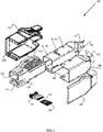
- FIG. 1 is a diagram of a secure adapter device 100, according to an example embodiment. It is to be noted that the components are shown schematically in greatly simplified form, with only those components relevant to understanding of the embodiments being illustrated.
- the secure adapter device 100 includes main housing 110, a first side cover 120, a second side cover 130, a first side shell housing 140, and a second shell housing 150.
- main housing 110 Internal to the main shell housing 110 is an integrated adapter 160 built into the main shell housing 150.
- the adapter 160 permits insertion and removal of a different type of peripheral device, such as the micro SD card 170 in the FIG. 1 .
- the main housing 150 also includes a terminal connector 111 by which an assembled version of the secure adapter device 100 can be interfaced to a corresponding peripheral port on a host computer terminal.
- the main housing 150 also includes a latching mechanism 112 by which the main housing 150 is secured into an assembled version of the secure adapter device 100.
- the latching mechanism 112 (described more completely below) also provides resistance against and within a slot 131 formed in the second side cover 130 in an assembled version of the secure adapter device 100.
- the main housing 150 is adapted to slide into the second shell housing 150.
- the first shell housing 140 includes apertures 141 that slide over, align with, and latch onto raised knobs 151 of the second housing 150.
- the second housing 150 includes a rearward extending appendage 152 that snaps and fits snugly against the first shell housing's corresponding rearward appendage 142.
- the second side cover 130 is then maneuvered over the combination of the main housing 110 that is inside of the second shell housing 150 with the attached first side housing 140, such that the latching mechanism 112 is interfaced into slot 131.
- the first side cover 120 is then aligned and snapped into the open end of the second side over 130 forming an assembled version of the secure adapter device 100 (shown in the FIGS. 2A and 2B ).
- the terminal 111 is a USB terminal for a 12-volt (V) host terminal peripheral port.
- V 12-volt
- Many retail terminals for Point-Of-Sale (POS) terminals or Self-Service Terminals (SST) include internal 12 V USB ports that are internal to a housing of the terminal and are not noticeable or available from an exterior surface of the housing. This was done to permit USB compatible peripherals to be integrated into the housing, such ports can and do support a connection for secure adapter device 100.
- the secure adapter device 100 also includes a self-latching mechanism 112 that secures the secure adapter device 100 within the 12 V USB host terminal peripheral port, preventing easy removal of the secure adapter device 100 from the internal 12V USB host terminal peripheral port.
- the self-latching mechanism 112 secures the secure adapter device 100 to the port into which it is interfaced (inserted) by exerting force against an inside top of the peripheral port.
- An operator uses a thumb to press down on sell-latching mechanism 112, which allows the terminal 111 and front portion of the secure adapter device 100 to fit inside the 12 V port of the hot terminal.
- the self-latching mechanism 112 impedes insertion of the terminal 111 into the port because mechanism 112 is biased to a state that exceeds a size of the opening for the peripheral port.
- the area surrounding the front of the secure adapter device 100 is decreased to a sufficient size to fit into a 12 V USB peripheral connection port.
- the operator releases the downward pressure from the thumb, and the self-latching mechanism 112 returns to its initial biased state, which results in a portion of 112 that is inside the 12 V USB port to exert an upward force against the inside and top portion of the 12 V USB port.
- the force is sufficient enough to prevent removal of the secure adapter device 100 from the port unless 112 is pressed down by the operator.
- self-latching mechanism can be used as well, such as side appendages from the sides of outer sides of terminal 111 having a rounded shape that permit the side appendages to fold in when the terminal 111 is slid into the 12 V USB port.
- the side appendages are biased to be extended from the sides, such that once the terminal 111 is inserted into the port, the appendages return to the biased state and exert pressure on the corresponding inside portions of the port.
- a lever or button may be provided that allows the side appendages to collapse for removal of the secure adapter device 100 from the port.
- the appendages may also be manufactured on the portion 113 of the secure adapter device 100 located above the terminal 111. In some cases, a single rather than dual appendages may be used as a self-latching mechanism.
- the adapter 160 is accessible from the main housing 110 such that a micro SD card 170, SIM card, or SD card can be inserted and removed from a slot of the adapter 161.
- Access to the slot 161 may be obscured by the outer surface of the main housing 110 and accessible through a push button or lever that causes a portion of the main housing 110 to open for access to the slot 161.
- access to the slot 161 may be manufactured such that is accessible from the outer surface of the main housing 110 on a side surface, top surface, rear surface without removing any portion of the main housing 110 for purposes of inserting the micro SD card 170, SIM card, or SD card.
- access to the slot 161 is through aperture 113 providing it is a sufficient distance inside aperture 113 so as to not interfere with componentry associated with the host peripheral port when the secure adapter device 100 is secured into the host peripheral port.
- the adapter 160 is built into the main housing 110 through wiring the USB connection pins of the terminal 111 directly to the corresponding adapter pins of the adapter 160.
- the main housing 110 includes a female port connection that allows the adapter 160 having a male port end to connect within the main housing. This allows the adapter 160 to be removed and a different adapter 160 for a different type of card to be inserted.
- an adapter 160 having a slot 161 for connecting a micro SD card 170 can be removed from the main housing 110 and a different adapter inserted for connection a SIM card or an SD card.
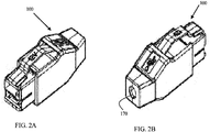
- FIG. 2A is a diagram of a front-facing view of an assembled secure adapter device, according to an example embodiment.
- FIG. 2B is a diagram of a rear-facing view of an assembled powered and security peripheral adapter device, according to an example embodiment.
- the rear-facing view includes a rubber plug 170 that seals the appendages 152 and 142 together and prevents disassembly of the device 100 into the component pieces illustrated in the FIG. 1 .
- the plug 170 may be removed by turning the plug 170 in a predesignated direction for a quarter turn.
- the plug includes a knob that fits into the opening made by the appendages 152 and 142.
- the opening formed by the adjoined appendages 152 and 142 may also include a groove/ridge that forms nearly a complete circle within the adjoined appendages 152 and 142 but includes a portion that lacks the groove/ridge.
- the plug 170 can be inserted into the opening by aligning the plug knob to the portion within the opening that lacks the groove or ridge and then twisting the plug 170 in either direction, such that the knob is now behind the groove or ridge and locked into place sealing the device 100.
- the plug 170 having a knob is but one example of how the device 100 can be sealed, others may be used as well without departing from the beneficial teachings presented herein.
- a small latch may be released that allows the component pieces to be separated through insertion of a small specialized key or pin into a hole through one or more of the components.
- the specialized key or pin trips the latch, allowing the outer component pieces to separate.
- This same type of pin or key based approach may also be used to gain access to the main housing 110 for purposes of accessing slot 161 of adapter 160 to remove micro SD card 170 and insert a different micro SD card.
- the contents and programming of the micro SD card 170 can be any process or set of processes intended to be secure.
- the secure adapter device 100 permits the micro SD card 170 to be made secure almost as if the micro SD card 170 was an internal hardware component of the host computer to which it is ultimately attached. Once inserted into a 12 V USB port, the secure adapter device 100 is secured within the port through activation of the self-latching mechanism 112 (as discussed above). Furthermore, once removed from the port, the secure adapter device 100 requires a specific technique by which the components of the secure adapter device 100 can be disassembled and by which access can be made to the micro SD card 170 from the slot 161 of the adapter 160. In this way, the micro SD card 170 is secured within the secure adapter device 100.
- the adapter 160 is a USB to micro SD adapter (as is illustrated in the FIG. 1 ).
- the adapter 160 is a USB to SD adapter.
- the adapter 160 is a USB to SIM adapter.
- the adapter 160 is removable for the main housing 110 and capable of being swapped out with a different adapter 160.
- the secure adapter device 100 is a 12 V secure adapter device 100 designed to fit into and interface with a 12 V USB port of a host terminal.
- the 12 V USB port is located within an internal housing of the host terminal and is not accessible from an exterior surface of the housing.
- the housing has to be removed from the host terminal to access the 12 V USB port into which the secure adapter device 100 is securely inserted with self-latching via the self-latching mechanism 112.
Landscapes
- Engineering & Computer Science (AREA)
- Theoretical Computer Science (AREA)
- Physics & Mathematics (AREA)
- General Physics & Mathematics (AREA)
- Computer Hardware Design (AREA)
- Microelectronics & Electronic Packaging (AREA)
- General Engineering & Computer Science (AREA)
- Connector Housings Or Holding Contact Members (AREA)
Abstract
Description
- Many computer-based terminals include peripheral ports for connecting peripheral devices. These devices are interfaced to a host terminal using a variety of different interface port formats, such as secure digital (SD), micro SD, subscriber identity module (SIM), and Universal Serial Bus (USB). Most host terminals include a variety of ports that support USB dongles. Rarely does a host terminal include ports for SD cards, micro SD cards, or SIM cards. Such devices are meant to be portable; as a result, insertion and removal of the devices from the host terminal are insecurely achieved by an operator.
- The portability of the devices is attractive and convenient, but such devices do not conform to many governmental security regulations required of businesses with respect to capturing and tracking audit information for hardware devices used in commerce.
- In various embodiments, secure adapter devices are presented.
- According to an embodiment, a secure peripheral adapter device is provided. The device includes a terminal, a self-latching mechanism, and an adapter. The terminal is adapted to be inserted into a port of a host terminal. The self-latching mechanism is adapted to secure the terminal inside the port and activated upon insertion of the terminal into the port. The adapter includes an adapter slot terminal, the adapter is coupled to the terminal and the adapter slot terminal is adapted to receive a second device for interfacing the second device to the host terminal through the device.
- According to aspects of the invention, the following examples, numbered 1-20 disclose:
- 1. A device, comprising: a terminal adapted to be inserted into a port of a host terminal; a self-latching mechanism adapted to secure the terminal inside the port and activated upon insertion of the terminal into the port; an adapter includes an adapter slot terminal, wherein the adapter is coupled to the terminal and the adapter slot terminal is adapted to receive a second device.
- 2. The device of example 1 optionally further comprising: a main housing comprising the terminal, the self-latching mechanism and the adapter.
- 3. The device of examples 1-2 optionally further comprising, a shell housing adapted to slide over and encase the main housing with the self-latching mechanism remaining outside the shell housing.
- 4. The device of examples 1-3, wherein the shell housing optionally includes a first appendage that extends outwardly from a rear of the shell housing opposite a side associated with the terminal.
- 5. The device of examples 1-4 optionally further comprising, a shell housing cover adapted to securely snap over the shell housing.
- 6. The device of examples 1-5 optionally further comprising, wherein the shell housing cover includes a second appendage the extends outwardly from a rear of the shell housing cover and aligns with the first appendage of the shell housing, the first appendage and the second appendage adapted to form an aperture at adjoined ends.
- 7. The device of examples 1-6 optionally further comprising, two side covers adapted to snap together and encase the shell housing cover and the shell housing.
- 8. The device of examples 1-7, wherein, optionally, an inside portion of the adjoined ends of the first appendage and the second appendage form a discontinuous protruding ridge.
- 9. The device of examples 1-8 optionally further comprising, a rubber or plastic plug including a protruding knob, wherein the plug adapted to fit inside the aperture with the protruding knob maneuvered to fit behind a portion of the discontinuous protruding ridge to seal the device and lock the shell housing and shell housing cover together.
- 10. The device of examples 1-9, wherein the device optionally is adapted to be disassembled for access to the adapter slot terminal of the adapter located in or on the main housing for removing the second device or inserting a different device into the adapter slot terminal.
- 11. A Universal Serial Bus (USB) adapter device, comprising: a main housing comprising: a terminal, a micro Secure Digital (SD)-to-USB adapter, and a self-latching mechanism; a removable shell adapted to securely encase the main housing; the terminal adapted to be inserted into a 12 Volt USB port of a host terminal; the micro SD-to-USB coupled to pins of the terminal within the main housing; the micro SD-to-USB includes a micro SD slot terminal adapted to receive micro SD cards inserted into the micro SD slot terminal; and the self-latching mechanism adapted to lock the main housing in to the 12 Volt USB port when the USB adapter device is inserted into the 12 Volt USB port.
- 12. The USB adapter device of example 11, wherein the self-latching mechanism optionally includes a lever adapted to unlock or release the main housing from the 12 Volt USB port upon removal of the USB adapter device from the 12 Volt USB port.
- 13. The USB adapter device of examples 11-12, wherein the main housing optionally includes a key activated latch adapted to open a cover of the main housing when a key is inserted into a hole of the main housing to trip an internal latch, wherein the micro SD slot terminal is accessed with the cover of the main housing opened.
- 14. The USB adapter device of examples 11-13, wherein the micro SD slot terminal is accessible from an exterior facing surface of the main housing.
- 15. The USB adapter device of examples 11-14, wherein the removable shell optionally includes a locking or sealing mechanism that locks or seals the removable shell around the main housing.
- 16. The USB adapter device of examples 11-15, wherein the locking or sealing mechanism is optionally situated on an end opposite a second end where the terminal is located on the main housing.
- 17. The USB adapter device of examples 11-16, wherein the locking or sealing mechanism optionally includes an internal latch or a plug.
- 18. A device adapter, comprising: a terminal adapted to be inserted and removed from a host terminal port; a second terminal adapted to receive second devices within the device adapter; a self-latching mechanism adapted to self-latch the terminal to the host terminal port when the terminal is inserted into the host terminal port; and a secure housing adapted to restrict access to the second terminal, wherein the secure housing when disassembled provides access to the second terminal for insertion and removal of the second devices.
- 19. The device adapter of example 18, wherein the device adapter is optionally a 12 V micro Secure Digital (SD) to Universal Serial Bus (USB) adapter.
- 20. The device adapter of example 19, wherein the host terminal port is optionally an internal 12 V USB port located within a housing of a host terminal, and wherein the host terminal is a Point-Of-Sale (POS) terminal or a Self-Service Terminal (SST).
- These and other aspects of the present invention will be apparent from the following specific description, given by way of example, with reference to the accompanying drawings, in which:
-
FIG. 1 is a diagram of a secure adapter device, according to an example embodiment. -
FIG. 2A is a diagram of a front-facing view of an assembled secure adapter device, according to an example embodiment. -
FIG. 2B is a diagram of a rear-facing view of an assembled powered and security adapter device, according to an example embodiment. -
FIG. 1 is a diagram of asecure adapter device 100, according to an example embodiment. It is to be noted that the components are shown schematically in greatly simplified form, with only those components relevant to understanding of the embodiments being illustrated. - Furthermore, the various components (that are identified in the
FIG. 1 ) are illustrated and the arrangement of the components is presented for purposes of illustration only. It is to be noted that other arrangements with more or less components are possible without departing from thesecure adapter device 100 presented herein and below. - The
secure adapter device 100 includesmain housing 110, afirst side cover 120, asecond side cover 130, a firstside shell housing 140, and asecond shell housing 150. Internal to themain shell housing 110 is an integratedadapter 160 built into themain shell housing 150. Theadapter 160 permits insertion and removal of a different type of peripheral device, such as themicro SD card 170 in theFIG. 1 . - The
main housing 150 also includes aterminal connector 111 by which an assembled version of thesecure adapter device 100 can be interfaced to a corresponding peripheral port on a host computer terminal. Themain housing 150 also includes alatching mechanism 112 by which themain housing 150 is secured into an assembled version of thesecure adapter device 100. The latching mechanism 112 (described more completely below) also provides resistance against and within aslot 131 formed in thesecond side cover 130 in an assembled version of thesecure adapter device 100. - The
main housing 150 is adapted to slide into thesecond shell housing 150. Thefirst shell housing 140 includesapertures 141 that slide over, align with, and latch onto raisedknobs 151 of thesecond housing 150. Thesecond housing 150 includes a rearward extendingappendage 152 that snaps and fits snugly against the first shell housing's correspondingrearward appendage 142. Thesecond side cover 130 is then maneuvered over the combination of themain housing 110 that is inside of thesecond shell housing 150 with the attachedfirst side housing 140, such that thelatching mechanism 112 is interfaced intoslot 131. Thefirst side cover 120 is then aligned and snapped into the open end of the second side over 130 forming an assembled version of the secure adapter device 100 (shown in theFIGS. 2A and 2B ). - In an embodiment, the terminal 111 is a USB terminal for a 12-volt (V) host terminal peripheral port. Many retail terminals for Point-Of-Sale (POS) terminals or Self-Service Terminals (SST) include internal 12 V USB ports that are internal to a housing of the terminal and are not noticeable or available from an exterior surface of the housing. This was done to permit USB compatible peripherals to be integrated into the housing, such ports can and do support a connection for
secure adapter device 100. - The
secure adapter device 100 also includes a self-latchingmechanism 112 that secures thesecure adapter device 100 within the 12 V USB host terminal peripheral port, preventing easy removal of thesecure adapter device 100 from the internal 12V USB host terminal peripheral port. - The self-latching
mechanism 112 secures thesecure adapter device 100 to the port into which it is interfaced (inserted) by exerting force against an inside top of the peripheral port. An operator uses a thumb to press down on sell-latching mechanism 112, which allows the terminal 111 and front portion of thesecure adapter device 100 to fit inside the 12 V port of the hot terminal. In an initial biased state, the self-latchingmechanism 112 impedes insertion of the terminal 111 into the port becausemechanism 112 is biased to a state that exceeds a size of the opening for the peripheral port. When the user presses down on 112, the area surrounding the front of thesecure adapter device 100 is decreased to a sufficient size to fit into a 12 V USB peripheral connection port. Once inserted into the port, the operator releases the downward pressure from the thumb, and the self-latchingmechanism 112 returns to its initial biased state, which results in a portion of 112 that is inside the 12 V USB port to exert an upward force against the inside and top portion of the 12 V USB port. The force is sufficient enough to prevent removal of thesecure adapter device 100 from the port unless 112 is pressed down by the operator. - It is noted that other self-latching mechanism can be used as well, such as side appendages from the sides of outer sides of
terminal 111 having a rounded shape that permit the side appendages to fold in when the terminal 111 is slid into the 12 V USB port. Again, the side appendages are biased to be extended from the sides, such that once the terminal 111 is inserted into the port, the appendages return to the biased state and exert pressure on the corresponding inside portions of the port. A lever or button may be provided that allows the side appendages to collapse for removal of thesecure adapter device 100 from the port. The appendages may also be manufactured on theportion 113 of thesecure adapter device 100 located above theterminal 111. In some cases, a single rather than dual appendages may be used as a self-latching mechanism. - The
adapter 160 is accessible from themain housing 110 such that amicro SD card 170, SIM card, or SD card can be inserted and removed from a slot of theadapter 161. - Access to the
slot 161 may be obscured by the outer surface of themain housing 110 and accessible through a push button or lever that causes a portion of themain housing 110 to open for access to theslot 161. - In another case, access to the
slot 161 may be manufactured such that is accessible from the outer surface of themain housing 110 on a side surface, top surface, rear surface without removing any portion of themain housing 110 for purposes of inserting themicro SD card 170, SIM card, or SD card. - In an embodiment, access to the
slot 161 is throughaperture 113 providing it is a sufficient distance insideaperture 113 so as to not interfere with componentry associated with the host peripheral port when thesecure adapter device 100 is secured into the host peripheral port. - In an embodiment, the
adapter 160 is built into themain housing 110 through wiring the USB connection pins of the terminal 111 directly to the corresponding adapter pins of theadapter 160. - In an embodiment, the
main housing 110 includes a female port connection that allows theadapter 160 having a male port end to connect within the main housing. This allows theadapter 160 to be removed and adifferent adapter 160 for a different type of card to be inserted. For example, anadapter 160 having aslot 161 for connecting amicro SD card 170 can be removed from themain housing 110 and a different adapter inserted for connection a SIM card or an SD card. -
FIG. 2A is a diagram of a front-facing view of an assembled secure adapter device, according to an example embodiment. -
FIG. 2B is a diagram of a rear-facing view of an assembled powered and security peripheral adapter device, according to an example embodiment. - The rear-facing view includes a
rubber plug 170 that seals theappendages device 100 into the component pieces illustrated in theFIG. 1 . Theplug 170 may be removed by turning theplug 170 in a predesignated direction for a quarter turn. The plug includes a knob that fits into the opening made by theappendages appendages appendages plug 170 can be inserted into the opening by aligning the plug knob to the portion within the opening that lacks the groove or ridge and then twisting theplug 170 in either direction, such that the knob is now behind the groove or ridge and locked into place sealing thedevice 100. - It is noted that the
plug 170 having a knob is but one example of how thedevice 100 can be sealed, others may be used as well without departing from the beneficial teachings presented herein. For example, a small latch may be released that allows the component pieces to be separated through insertion of a small specialized key or pin into a hole through one or more of the components. The specialized key or pin trips the latch, allowing the outer component pieces to separate. This same type of pin or key based approach may also be used to gain access to themain housing 110 for purposes of accessingslot 161 ofadapter 160 to removemicro SD card 170 and insert a different micro SD card. - The contents and programming of the
micro SD card 170 can be any process or set of processes intended to be secure. Thesecure adapter device 100 permits themicro SD card 170 to be made secure almost as if themicro SD card 170 was an internal hardware component of the host computer to which it is ultimately attached. Once inserted into a 12 V USB port, thesecure adapter device 100 is secured within the port through activation of the self-latching mechanism 112 (as discussed above). Furthermore, once removed from the port, thesecure adapter device 100 requires a specific technique by which the components of thesecure adapter device 100 can be disassembled and by which access can be made to themicro SD card 170 from theslot 161 of theadapter 160. In this way, themicro SD card 170 is secured within thesecure adapter device 100. - In an embodiment, the
adapter 160 is a USB to micro SD adapter (as is illustrated in theFIG. 1 ). - In an embodiment, the
adapter 160 is a USB to SD adapter. - In an embodiment, the
adapter 160 is a USB to SIM adapter. - In an embodiment, the
adapter 160 is removable for themain housing 110 and capable of being swapped out with adifferent adapter 160. - In an embodiment, the
secure adapter device 100 is a 12 Vsecure adapter device 100 designed to fit into and interface with a 12 V USB port of a host terminal. - In an embodiment, the 12 V USB port is located within an internal housing of the host terminal and is not accessible from an exterior surface of the housing. In other words, the housing has to be removed from the host terminal to access the 12 V USB port into which the
secure adapter device 100 is securely inserted with self-latching via the self-latchingmechanism 112. - The above description is illustrative, and not restrictive. Many other embodiments will be apparent to those of skill in the art upon reviewing the above description. The scope of embodiments should therefore be determined with reference to the appended claims, along with the full scope of equivalents to which such claims are entitled.
- In the foregoing description of the embodiments, various features are grouped together in a single embodiment for the purpose of streamlining the disclosure. This method of disclosure is not to be interpreted as reflecting that the claimed embodiments have more features than are expressly recited in each claim. Rather, as the following claims reflect, inventive subject matter lies in less than all features of a single disclosed embodiment. Thus the following claims are hereby incorporated into the Description of the Embodiments, with each claim standing on its own as a separate exemplary embodiment.
Claims (10)
- A device, comprising:a terminal adapted to be inserted into a port of a host terminal;a self-latching mechanism adapted to secure the terminal inside the port and activated upon insertion of the terminal into the port;an adapter includes an adapter slot terminal, wherein the adapter is coupled to the terminal and the adapter slot terminal is adapted to receive a second device.
- The device of claim 1 further comprising: a main housing comprising the terminal, the self-latching mechanism and the adapter.
- The device of claim 2 further comprising, a shell housing adapted to slide over and encase the main housing with the self-latching mechanism remaining outside the shell housing.
- The device of claim 3, wherein the shell housing includes a first appendage that extends outwardly from a rear of the shell housing opposite a side associated with the terminal.
- The device of claim 4 further comprising, a shell housing cover adapted to securely snap over the shell housing.
- The device of claim 5 further comprising, wherein the shell housing cover includes a second appendage the extends outwardly from a rear of the shell housing cover and aligns with the first appendage of the shell housing, the first appendage and the second appendage adapted to form an aperture at adjoined ends.
- The device of claim 6 further comprising, two side covers adapted to snap together and encase the shell housing cover and the shell housing.
- The device of claim 7, wherein an inside portion of the adjoined ends of the first appendage and the second appendage form a discontinuous protruding ridge.
- The device of claim 8 further comprising, a rubber or plastic plug including a protruding knob, wherein the plug adapted to fit inside the aperture with the protruding knob maneuvered to fit behind a portion of the discontinuous protruding ridge to seal the device and lock the shell housing and shell housing cover together.
- The device of claim 9, wherein the device is adapted to be disassembled for access to the adapter slot terminal of the adapter located in or on the main housing for removing the second device or inserting a different device into the adapter slot terminal.
Applications Claiming Priority (1)
| Application Number | Priority Date | Filing Date | Title |
|---|---|---|---|
| US16/526,719 US10938154B2 (en) | 2019-07-30 | 2019-07-30 | Secure adapter device |
Publications (1)
| Publication Number | Publication Date |
|---|---|
| EP3772142A1 true EP3772142A1 (en) | 2021-02-03 |
Family
ID=69061188
Family Applications (1)
| Application Number | Title | Priority Date | Filing Date |
|---|---|---|---|
| EP19220181.2A Withdrawn EP3772142A1 (en) | 2019-07-30 | 2019-12-31 | Secure adapter device |
Country Status (2)
| Country | Link |
|---|---|
| US (1) | US10938154B2 (en) |
| EP (1) | EP3772142A1 (en) |
Citations (2)
| Publication number | Priority date | Publication date | Assignee | Title |
|---|---|---|---|---|
| US20070274117A1 (en) * | 2002-04-26 | 2007-11-29 | Salazar Jeffrey A | Retractable card adapter |
| US7985091B1 (en) * | 2010-12-07 | 2011-07-26 | Hong Fu Jin Precision Industry (Shenzhen) Co., Ltd. | Locking mechanism and information handling system using the same |
Family Cites Families (19)
| Publication number | Priority date | Publication date | Assignee | Title |
|---|---|---|---|---|
| US6254418B1 (en) * | 2000-08-16 | 2001-07-03 | The Jpm Company | Latch release |
| US6364685B1 (en) * | 2000-11-03 | 2002-04-02 | Randy Marshall Manning | Connector with articulated latch |
| US7037129B2 (en) * | 2002-04-26 | 2006-05-02 | The Siemon Company | Axial latch actuator with locking wedge |
| AU2003240938A1 (en) * | 2002-05-31 | 2003-12-19 | Simpletech, Inc. | Removable storage device |
| TW547838U (en) * | 2002-12-04 | 2003-08-11 | Benq Corp | Connector with changeable connecting manner |
| TWI232909B (en) * | 2004-03-12 | 2005-05-21 | Jin Tay Ind Co Ltd | Connector lock for a universal serial bus port |
| US7097472B2 (en) * | 2004-09-08 | 2006-08-29 | Hewlett-Packard Development Company, L.P. | Universal serial bus plug |
| TWM266493U (en) * | 2004-10-26 | 2005-06-01 | Carry Computer Eng Co Ltd | Data access device for memory card |
| US7329137B2 (en) * | 2005-10-05 | 2008-02-12 | Tyco Electronics Corporation | Modular plug with slider latch |
| TWM286969U (en) * | 2005-10-18 | 2006-02-01 | Datafab Sys Inc | Card reader of memory card type |
| TW200840163A (en) * | 2007-03-16 | 2008-10-01 | En-Min Jow | Memory card, memory card connector and memory device of its combination |
| US7635272B2 (en) * | 2006-08-17 | 2009-12-22 | Acco Brands Usa Llc | USB port locking and blocking device |
| US7540749B1 (en) * | 2008-02-06 | 2009-06-02 | Tyco Electronics Corporation | Connector assemblies and systems |
| US7959459B2 (en) * | 2009-01-30 | 2011-06-14 | Dell Products L.P. | Retractable information handling system cable |
| CN101872408A (en) * | 2009-04-21 | 2010-10-27 | 鸿富锦精密工业(深圳)有限公司 | Usb card reader |
| ES2395358B1 (en) * | 2011-02-08 | 2014-04-25 | Tyco Electronics Corporation | SINGLE ACTION CONNECTOR |
| CN102858115A (en) * | 2011-06-29 | 2013-01-02 | 鸿富锦精密工业(深圳)有限公司 | Universal serial bus device |
| CN103257407B (en) * | 2012-02-20 | 2015-11-25 | 泰科电子(上海)有限公司 | Connector and connector assembly |
| KR101406202B1 (en) * | 2013-02-01 | 2014-06-12 | 안창훈 | An apparatus for locking usb port |
-
2019
- 2019-07-30 US US16/526,719 patent/US10938154B2/en active Active
- 2019-12-31 EP EP19220181.2A patent/EP3772142A1/en not_active Withdrawn
Patent Citations (2)
| Publication number | Priority date | Publication date | Assignee | Title |
|---|---|---|---|---|
| US20070274117A1 (en) * | 2002-04-26 | 2007-11-29 | Salazar Jeffrey A | Retractable card adapter |
| US7985091B1 (en) * | 2010-12-07 | 2011-07-26 | Hong Fu Jin Precision Industry (Shenzhen) Co., Ltd. | Locking mechanism and information handling system using the same |
Non-Patent Citations (2)
| Title |
|---|
| C K C ANONYMOUS: "DATA SHEET", 31 December 2010 (2010-12-31), Internet, XP055689433, Retrieved from the Internet <URL:https://www.delock.de/produkte/G_91678/merkmale.html> [retrieved on 20200427] * |
| WWW.POWEREDUSB.ORG: "Retail USB, USB PlusPower, USB +Power", 11 February 2005 (2005-02-11), XP055224858, Retrieved from the Internet <URL:http://www.poweredusb.org/pdf/PoweredUSB_v08g.pdf> [retrieved on 20151030] * |
Also Published As
| Publication number | Publication date |
|---|---|
| US20210036461A1 (en) | 2021-02-04 |
| US10938154B2 (en) | 2021-03-02 |
Similar Documents
| Publication | Publication Date | Title |
|---|---|---|
| EP2737581B1 (en) | Blockout device for usb port | |
| CN108136926B (en) | Electric mobility charging interface sockets and modular closures | |
| US6808411B2 (en) | Fan holder with electrical connector socket | |
| US6129572A (en) | Electrical connector with latch to retain IC card | |
| US20060234533A1 (en) | Portable memory device with protective cap | |
| US20090067142A1 (en) | Retaining mechanism for circuit card | |
| US6173843B1 (en) | Computer expansion card latching and retention mechanism | |
| KR20010007014A (en) | Adaptor for connecting card | |
| KR101627697B1 (en) | Connect assembly for dual memory card and card tray used in the same | |
| EP3309652B1 (en) | Docking station for electronic device | |
| JPH0581965U (en) | Low insertion / removal force connector | |
| EP1638382B1 (en) | System and method of a computer card slot and bezel | |
| US7184274B2 (en) | Flash memory encryption device | |
| JP7807482B2 (en) | Near field along with far field to ensure device is connected or secured | |
| CN105896171A (en) | Lever-type connector | |
| US10938154B2 (en) | Secure adapter device | |
| US10185686B2 (en) | Connecting a peripheral device | |
| TWI749863B (en) | Protecting cover adapted for a connecting port and related connecting port device | |
| US7413453B2 (en) | Card connector | |
| TW200541180A (en) | Low profile interface connector | |
| US20020016103A1 (en) | Unlocking aid | |
| US20070087601A1 (en) | Card connector with anti-mismating device | |
| JP2833452B2 (en) | Card edge connector | |
| US6498729B2 (en) | Expansion module | |
| US11301409B2 (en) | Input/Output modules |
Legal Events
| Date | Code | Title | Description |
|---|---|---|---|
| PUAI | Public reference made under article 153(3) epc to a published international application that has entered the european phase |
Free format text: ORIGINAL CODE: 0009012 |
|
| STAA | Information on the status of an ep patent application or granted ep patent |
Free format text: STATUS: REQUEST FOR EXAMINATION WAS MADE |
|
| 17P | Request for examination filed |
Effective date: 20191231 |
|
| AK | Designated contracting states |
Kind code of ref document: A1 Designated state(s): AL AT BE BG CH CY CZ DE DK EE ES FI FR GB GR HR HU IE IS IT LI LT LU LV MC MK MT NL NO PL PT RO RS SE SI SK SM TR |
|
| AX | Request for extension of the european patent |
Extension state: BA ME |
|
| STAA | Information on the status of an ep patent application or granted ep patent |
Free format text: STATUS: EXAMINATION IS IN PROGRESS |
|
| 17Q | First examination report despatched |
Effective date: 20220818 |
|
| P01 | Opt-out of the competence of the unified patent court (upc) registered |
Effective date: 20230506 |
|
| STAA | Information on the status of an ep patent application or granted ep patent |
Free format text: STATUS: THE APPLICATION HAS BEEN WITHDRAWN |
|
| RAP3 | Party data changed (applicant data changed or rights of an application transferred) |
Owner name: NCR VOYIX CORPORATION |
|
| 18W | Application withdrawn |
Effective date: 20240207 |