EP3772084A1 - Focus adjustment method for charged particle beam device and charged particle beam device - Google Patents
Focus adjustment method for charged particle beam device and charged particle beam device Download PDFInfo
- Publication number
- EP3772084A1 EP3772084A1 EP20187053.2A EP20187053A EP3772084A1 EP 3772084 A1 EP3772084 A1 EP 3772084A1 EP 20187053 A EP20187053 A EP 20187053A EP 3772084 A1 EP3772084 A1 EP 3772084A1
- Authority
- EP
- European Patent Office
- Prior art keywords
- excitation current
- magnetic field
- field lens
- value
- search range
- Prior art date
- Legal status (The legal status is an assumption and is not a legal conclusion. Google has not performed a legal analysis and makes no representation as to the accuracy of the status listed.)
- Granted
Links
Images



Classifications
-
- H—ELECTRICITY
- H01—ELECTRIC ELEMENTS
- H01J—ELECTRIC DISCHARGE TUBES OR DISCHARGE LAMPS
- H01J37/00—Discharge tubes with provision for introducing objects or material to be exposed to the discharge, e.g. for the purpose of examination or processing thereof
- H01J37/02—Details
- H01J37/21—Means for adjusting the focus
-
- H—ELECTRICITY
- H01—ELECTRIC ELEMENTS
- H01J—ELECTRIC DISCHARGE TUBES OR DISCHARGE LAMPS
- H01J37/00—Discharge tubes with provision for introducing objects or material to be exposed to the discharge, e.g. for the purpose of examination or processing thereof
- H01J37/02—Details
- H01J37/04—Arrangements of electrodes and associated parts for generating or controlling the discharge, e.g. electron-optical arrangement or ion-optical arrangement
- H01J37/10—Lenses
- H01J37/14—Lenses magnetic
-
- H—ELECTRICITY
- H01—ELECTRIC ELEMENTS
- H01J—ELECTRIC DISCHARGE TUBES OR DISCHARGE LAMPS
- H01J37/00—Discharge tubes with provision for introducing objects or material to be exposed to the discharge, e.g. for the purpose of examination or processing thereof
- H01J37/02—Details
- H01J37/22—Optical, image processing or photographic arrangements associated with the tube
-
- H—ELECTRICITY
- H01—ELECTRIC ELEMENTS
- H01J—ELECTRIC DISCHARGE TUBES OR DISCHARGE LAMPS
- H01J37/00—Discharge tubes with provision for introducing objects or material to be exposed to the discharge, e.g. for the purpose of examination or processing thereof
- H01J37/26—Electron or ion microscopes; Electron or ion diffraction tubes
-
- H—ELECTRICITY
- H01—ELECTRIC ELEMENTS
- H01J—ELECTRIC DISCHARGE TUBES OR DISCHARGE LAMPS
- H01J37/00—Discharge tubes with provision for introducing objects or material to be exposed to the discharge, e.g. for the purpose of examination or processing thereof
- H01J37/26—Electron or ion microscopes; Electron or ion diffraction tubes
- H01J37/28—Electron or ion microscopes; Electron or ion diffraction tubes with scanning beams
-
- H—ELECTRICITY
- H01—ELECTRIC ELEMENTS
- H01J—ELECTRIC DISCHARGE TUBES OR DISCHARGE LAMPS
- H01J2237/00—Discharge tubes exposing object to beam, e.g. for analysis treatment, etching, imaging
- H01J2237/153—Correcting image defects, e.g. stigmators
- H01J2237/1532—Astigmatism
-
- H—ELECTRICITY
- H01—ELECTRIC ELEMENTS
- H01J—ELECTRIC DISCHARGE TUBES OR DISCHARGE LAMPS
- H01J2237/00—Discharge tubes exposing object to beam, e.g. for analysis treatment, etching, imaging
- H01J2237/21—Focus adjustment
- H01J2237/216—Automatic focusing methods
-
- H—ELECTRICITY
- H01—ELECTRIC ELEMENTS
- H01J—ELECTRIC DISCHARGE TUBES OR DISCHARGE LAMPS
- H01J2237/00—Discharge tubes exposing object to beam, e.g. for analysis treatment, etching, imaging
- H01J2237/22—Treatment of data
- H01J2237/221—Image processing
Definitions
- the present invention relates to a focus adjustment method for a charged particle beam device, and a charged particle beam device.
- JP-A-1-220351 discloses an electron microscope in which focus adjustment is performed automatically.
- a magnetic field lens is typically employed as a lens used for focus adjustment.
- Focus adjustment is performed by, for example, varying the excitation current of the magnetic field lens used for focus adjustment in order to find a focus position.
- the excitation current of the lens used for focus adjustment is varied widely.
- focus adjustment cannot be performed with a high degree of precision due to the effects of hysteresis in the magnetic field lens.
- a focus adjustment method for a charged particle beam device having a magnetic field lens used for focus adjustment and an astigmatism corrector including:
- a charged particle beam device including:
- the control unit removes hysteresis from the magnetic field lens before and after varying the excitation current of the magnetic field lens within the focus search range, or in other words before and after widely varying the excitation current of the magnetic field lens, and therefore the effects of hysteresis in the magnetic field lens can be reduced.
- the control unit determines the optimum value of the stigma correction value by varying the excitation current of the magnetic field lens using the reference value of the excitation current as a reference, and therefore the amount by which the excitation current of the magnetic field lens is varied while determining the optimum value of the stigma correction value can be reduced. As a result, the effects of hysteresis in the magnetic field lens can be reduced.
- the charged particle beam device according to the invention may also be a device that performs specimen observation by irradiating the specimen with a charged particle beam (an ion beam or the like) other than an electron beam.
- a scanning electron microscope, a transmission electron microscope, a scanning transmission electron microscope, an electron probe microanalyzer, a focused ion beam device, or the like, for example, may be used as the charged particle beam device according to the invention.
- FIG. 1 is a diagram illustrating a configuration of an electron microscope 100 according to an embodiment of the invention.
- the electron microscope 100 is a scanning electron microscope.
- the electron microscope 100 includes an electron gun 10, a condenser lens 12, a deflector 14, an astigmatism corrector 16, an objective lens 18, a specimen stage 20, an electron detector 30, an energy-dispersive X-ray detector 40, and a control unit 50.
- the electron gun 10 generates an electron beam EB.
- the electron gun 10 emits the electron beam EB toward a specimen S after accelerating the electron beam EB by a predetermined accelerating voltage.
- the condenser lens 12 is a lens for condensing the electron beam EB emitted from the electron gun 10.
- the deflector 14 deflects the electron beam EB two-dimensionally. Using the deflector 14, an electron probe can be caused to scan the specimen S.
- the astigmatism corrector 16 corrects astigmatism. Using the astigmatism corrector 16, astigmatism can be corrected by creating astigmatism of an identical strength to the astigmatism of the lens in an orthogonal direction thereto.
- the control unit 50 sets a stigma correction value, whereupon the astigmatism corrector 16 creates astigmatism corresponding to the set stigma correction value.
- the objective lens 18 is a lens for condensing the electron beam EB on the specimen S.
- the electron probe is formed by condensing the electron beam EB using the condenser lens 12 and the objective lens 18.
- the objective lens 18 is a magnetic field lens that is caused to generate a lens action using a magnetic field.
- the objective lens 18 includes an electromagnetic field coil for generating a magnetic field, and the strength of the lens action can be controlled in accordance with an excitation current supplied to the electromagnetic field coil.
- the objective lens 18 functions as a focus adjustment lens.
- the focus adjustment lens may be constituted by a plurality of lenses.
- the focus adjustment lens may be a combination of the objective lens 18 and an aperture angle control lens, not shown in the drawing.
- An aperture angle control lens is a lens for automatically optimizing an aperture angle with respect to the objective lens 18.
- the specimen stage 20 supports the specimen S.
- the specimen S is placed on the specimen stage 20.
- the specimen stage 20 includes a moving mechanism for moving the specimen S. By moving the specimen S using the specimen stage 20, the position in which the specimen S is irradiated with the electron beam EB can be moved.
- the electron detector 30 is a detector for detecting electrons emitted from the specimen S. By detecting the electrons emitted from the specimen S using the electron detector 30, a scanning electron microscope image (an SEM image) can be acquired.
- the electron detector 30 may be a backscattered-electron detector that detects backscattered electrons or a secondary electron detector that detects secondary electrons.
- the energy-dispersive X-ray detector 40 is a detector for acquiring an EDS spectrum by separating X-rays by energy.
- the energy-dispersive X-ray detector 40 detects a characteristic X-ray generated by the specimen S when the specimen S is irradiated with the electron beam EB.
- the control unit 50 controls the respective constituent units of the electron microscope 100.
- the control unit 50 is a computer including a central processing unit (CPU) and a storage device (a random access memory (RAM), a read only memory (ROM), or the like).
- the control unit 50 can perform various types of calculation processing and various types of control processing by having the CPU execute a program stored in the storage device. The processing performed by the control unit 50 will be described in detail below in "2. Operation".
- FIG. 2 is a flowchart illustrating an example of the processing executed by the control unit 50.
- FIGS. 3 and 4 are diagrams illustrating processing for removing hysteresis from the objective lens 18.
- control unit 50 starts the focus adjustment processing.
- control unit 50 sets the excitation current of the objective lens 18 outside a focus search range (S10).
- the control unit 50 sets the excitation current of the objective lens 18 outside the focus search range from the excitation current at the start of the processing.
- the excitation current of the objective lens 18 is set at a minimum excitation current from the excitation current at the start of the processing.
- the control unit 50 keeps the excitation current of the objective lens 18 outside the focus search range for a predetermined time. In so doing, hysteresis can be removed from the objective lens 18.
- the minimum excitation current is a minimum value of the excitation current supplied to the objective lens 18. Note that in this processing, as long as the excitation current of the objective lens 18 is set to be smaller than the lower limit of the focus search range, the excitation current of the objective lens 18 is not limited to the minimum excitation current.
- the excitation current of the objective lens 18 may be set at a larger excitation current than the upper limit of the focus search range.
- the excitation current of the objective lens 18 may be set at a maximum excitation current.
- hysteresis can be removed from the objective lens 18.
- the maximum excitation current is a maximum value of the excitation current supplied to the objective lens 18.
- control unit 50 acquires a plurality of SEM images having different focuses by varying the excitation current of the objective lens 18 within the focus search range, and searches for the excitation current at which a focus evaluation value is maximized (S12).
- the control unit 50 sets the objective lens 18 at the lower limit current of the focus search range from the minimum excitation current. Then, while varying the excitation current of the objective lens 18 from the lower limit toward the upper limit of the focus search range, or in other words while varying the objective lens 18 from weak excitation to strong excitation, the control unit 50 acquires a SEM image (an example of a first image) at each excitation current. For example, the control unit 50 varies the excitation current within the focus search range +1 step at a time from the lower limit to the upper limit, and acquires a SEM image at each step. The control unit 50 determines a focus evaluation value for each excitation current (each step) from the SEM images acquired at the respective excitation currents (the respective steps).
- +1 step denotes varying the excitation current of the objective lens 18 by a minimum unit toward the strong excitation side.
- -1 step denotes varying the excitation current of the objective lens 18 by the minimum unit toward the weak excitation side.
- the focus evaluation value is a value for evaluating the focus.
- the focus evaluation value takes a smaller value as focus deviation increases, and a maximum value when focusing is achieved.
- the focus evaluation value is an evaluation value acquired by a contrast method, for example, so that a steadily higher value is acquired as the contrast of the SEM image increases.
- the control unit 50 determines the focus evaluation value at each excitation current based on the SEM images acquired at the respective excitation currents.
- the method for evaluating the focus is not limited to the contrast method described above, and various well-known methods may be used.
- the focus may be evaluated by a Fourier transform method, which makes use of the fact that high-frequency components increase as the sharpness of the SEM image increases.
- control unit 50 determines the focus evaluation value at each excitation current by varying the excitation current from the lower limit to the upper limit of the focus search range, but instead, the control unit 50 may vary the excitation current from the lower limit to the upper limit of the focus search range and terminate the processing of step S12 at the point where the maximum focus evaluation value is found.
- control unit 50 sets the excitation current of the objective lens 18 outside the focus search range (S14).
- the control unit 50 sets the excitation current of the objective lens 18 outside the focus search range from the upper limit of the focus search range. For example, the excitation current of the objective lens 18 is set at the minimum excitation current.
- the control unit 50 keeps the excitation current of the objective lens 18 outside the focus search range for a predetermined time. In so doing, hysteresis can be removed from the objective lens 18.
- the processing of step S14 is performed in a similar manner to the processing of step S10 described above. Hence, in this embodiment, the processing for removing hysteresis (S10, S14) is performed before and after varying the excitation current of the objective lens 18 within the focus search range.
- control unit 50 sets the excitation current of the objective lens 18 at which the focus evaluation value is maximized as a reference value of the excitation current of the objective lens 18 (S18).
- control unit 50 sets the excitation current of the objective lens 18 forming the midpoint between the two maximum values as the reference value of the excitation current of the objective lens 18 (S20).
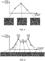
- FIGS. 5 and 6 are diagrams illustrating the processing for setting the reference value of the excitation current of the objective lens 18. Note that FIG. 5 illustrates a case in which the focus evaluation value has one maximum value, and FIG. 6 illustrates a case in which the focus evaluation value has two maximum values. Further, FIGS. 5 and 6 illustrate the SEM images acquired at the respective excitation currents and the focus evaluation values determined from the SEM images.
- the excitation current at which the focus evaluation value is maximized is set as the reference value.
- the excitation current forming the midpoint between the two maximum values is set as the reference value.
- the position of the midpoint between the two maximum values is the position of the disk of least confusion.
- the control unit 50 sets the reference value of the excitation current of the objective lens 18 in the manner described above.
- the control unit 50 then sets the excitation current of the objective lens 18 at the set reference value. In so doing, a focused state can be achieved.
- control unit 50 acquires a plurality of SEM images having different focuses by varying the excitation current of the objective lens 18 within the focus search range, and sets the reference value of the excitation current of the objective lens 18 based on the plurality of SEM images (S12, S16, S18, S20).
- the control unit 50 corrects astigmatism using the astigmatism corrector 16 (S22). More specifically, the control unit 50 acquires a plurality of SEM images having different focuses and different astigmatisms by varying the excitation current of the objective lens 18 using the set reference value as a reference and varying the stigma correction value of the astigmatism corrector 16 at each excitation current. The control unit 50 then determines an optimum value of the excitation current of the objective lens 18 and an optimum value of the stigma correction value based on the acquired plurality of SEM images.
- Varying the excitation current of the objective lens 18 using the reference value as a reference includes varying the excitation current to either the strong excitation side or the weak excitation side using the reference value as an initial value, for example.
- the optimum value of the excitation current of the objective lens 18 is the excitation current of the objective lens 18 at which focus deviation is minimized. Further, the optimum value of the stigma correction value of the astigmatism corrector 16 is a control value (an excitation current, for example) of the astigmatism corrector 16 at which astigmatism in the objective lens 18 is minimized.
- FIG. 7 is a flowchart illustrating an example of the processing (S22) for correcting astigmatism.
- the control unit 50 sets the excitation current of the objective lens 18 at the reference value determined in the processing of step S18 or step S20 (S100). As a result, a focused state is achieved.
- control unit 50 searches for the stigma correction value of the astigmatism corrector 16 at which the focus evaluation value is maximized by varying the stigma correction value with the excitation current of the objective lens 18 set at the reference value (S102).
- control unit 50 acquires a plurality of SEM images (an example of second images) having different stigma correction values by capturing SEM images while modifying the stigma correction value of the astigmatism corrector 16. The control unit 50 then determines a focus evaluation value for each of the plurality of SEM images, and acquires the stigma correction value at which the focus evaluation value is maximized.
- the optimum value of the stigma correction value when the excitation current of the objective lens 18 is set at the reference value can be acquired.
- control unit 50 shifts the excitation current of the objective lens 18 by +1 step from the reference value (S104).
- control unit 50 searches for the stigma correction value at which the focus evaluation value is maximized by varying the stigma correction value of the astigmatism corrector 16 with the excitation current of the objective lens 18 shifted by +1 step from the reference value (S 106).
- the processing of step S 106 is performed in a similar manner to the processing of step S102.
- the optimum value of the stigma correction value when the excitation current of the objective lens 18 is shifted by +1 step from the reference value can be acquired.
- control unit 50 compares the maximum value of the focus evaluation value when the excitation current of the objective lens 18 is set at the reference value, acquired in the processing of step S102, with the maximum value of the focus evaluation value when the excitation current of the objective lens 18 is shifted by +1 step from the reference value, acquired in the processing of step S106 (S108). In so doing, it is possible to ascertain which of these states results in more favorable focusing and less astigmatism.
- the control unit 50 shifts the excitation current of the objective lens 18 by +1 step (S110). As a result, the excitation current of the objective lens 18 is shifted by +2 steps from the reference value.
- the control unit 50 varies the stigma correction value of the astigmatism corrector 16 in order to find the stigma correction value at which the focus evaluation value is maximized (S112).
- the processing of step S112 is performed in a similar manner to the processing of step S102.
- the optimum value of the stigma correction value when the excitation current of the objective lens 18 is shifted by +2 steps from the reference value can be acquired.
- control unit 50 compares the maximum value of the focus evaluation value when the excitation current of the objective lens 18 is shifted by +1 step from the reference value, acquired in the processing of step S106, with the maximum value of the focus evaluation value when the excitation current of the objective lens 18 is shifted by +2 steps from the reference value, acquired in the processing of step S112 (S114).
- the control unit 50 Having determined that the maximum value of the focus evaluation value when the excitation current is shifted by +2 steps from the reference value equals or exceeds the maximum value of the focus evaluation value when the excitation current is shifted by +1 step from the reference value (Yes in S114), the control unit 50 returns to step S 110 and shifts the excitation current of the objective lens 18 by +1 step (S110). As a result, the excitation current of the objective lens 18 is shifted by +3 steps from the reference value. The control unit 50 then performs the processing of step S112 and the processing of step S 114.
- the control unit 50 repeats the processing of step S110, step S112, and step S114 until the maximum value of the focus evaluation value after shifting the excitation current of the objective lens 18 by +1 step becomes smaller than the maximum value of the focus evaluation value before shifting the excitation current of the objective lens 18 by +1 step.
- the control unit 50 sets a state in which the excitation current is shifted by +1 step from the reference value as the optimum value of the excitation current of the objective lens 18 and sets the optimum value of the stigma correction value when the excitation current is shifted by +1 step from the reference value as the optimum value of the stigma correction value of the astigmatism corrector 16 (S 116).
- the control unit 50 sets the excitation current of the objective lens 18 at the optimum value and sets the stigma correction value of the astigmatism corrector 16 at the optimum value.
- the control unit 50 shifts the excitation current of the objective lens 18 by -2 steps (S118). As a result, the excitation current of the objective lens 18 is shifted by -1 step from the reference value.
- the control unit 50 varies the stigma correction value of the astigmatism corrector 16 in order to find the stigma correction value at which the focus evaluation value is maximized (S 120).
- the processing of step S120 is performed in a similar manner to the processing of step S102.
- the optimum value of the stigma correction value when the excitation current of the objective lens 18 is shifted by -1 step from the reference value can be acquired.
- control unit 50 compares the maximum value of the focus evaluation value when the excitation current of the objective lens 18 is set at the reference value, acquired in the processing of step S102, with the maximum value of the focus evaluation value when the excitation current of the objective lens 18 is shifted by -1 step from the reference value, acquired in the processing of step S120 (S122).
- the control unit 50 shifts the excitation current of the objective lens 18 by -1 step (S 124). As a result, the excitation current of the objective lens 18 is shifted by -2 steps from the reference value.
- the control unit 50 varies the stigma correction value of the astigmatism corrector 16 in order to find the stigma correction value at which the focus evaluation value is maximized (S 126).
- the processing of step S126 is performed in a similar manner to the processing of step S102.
- the optimum value of the stigma correction value when the excitation current of the objective lens 18 is shifted by -2 steps from the reference value can be acquired.
- control unit 50 compares the maximum value of the focus evaluation value when the excitation current of the objective lens 18 is shifted by -1 step from the reference value, acquired in the processing of step S120, with the maximum value of the focus evaluation value when the excitation current of the objective lens 18 is shifted by -2 steps from the reference value, acquired in the processing of step S126 (S128).
- the control unit 50 Having determined that the maximum value of the focus evaluation value when the excitation current is shifted by -2 steps from the reference value equals or exceeds the maximum value of the focus evaluation value when the excitation current is shifted by -1 step from the reference value (Yes in S 128), the control unit 50 returns to step S124 and shifts the excitation current of the objective lens 18 by -1 step (S124). As a result, the excitation current of the objective lens 18 is shifted by -3 steps from the reference value. The control unit 50 then performs the processing of step S126 and the processing of step S128.
- the control unit 50 repeats the processing of step S124, step S126, and step S128 until the maximum value of the focus evaluation value after shifting the excitation current of the objective lens 18 by -1 step becomes smaller than the maximum value of the focus evaluation value before shifting the excitation current of the objective lens 18 by -1 step.
- the control unit 50 sets a state in which the excitation current is shifted by -1 step from the reference value as the optimum value of the excitation current of the objective lens 18 and sets the optimum value of the stigma correction value when the excitation current is shifted by -1 step from the reference value as the optimum value of the stigma correction value of the astigmatism corrector 16 (S 116).
- the control unit 50 sets the excitation current of the objective lens 18 at the optimum value and sets the stigma correction value of the astigmatism corrector 16 at the optimum value.
- the focus adjustment method for the electron microscope 100 includes acquiring a plurality of SEM images having different focuses by varying the excitation current of the objective lens 18 within the focus search range, and determining the reference value of the excitation current of the objective lens 18 based on the plurality of SEM images, removing hysteresis from the objective lens 18 by setting the excitation current of the objective lens 18 outside the focus search range before varying the excitation current of the objective lens 18 within the focus search range, and removing hysteresis from the objective lens 18 by setting the excitation current of the objective lens 18 outside the focus search range after varying the excitation current of the objective lens 18 within the focus search range.
- the focus adjustment method also includes acquiring a plurality of SEM images having different focuses and different astigmatisms by varying the excitation current of the objective lens 18 using the reference value of the excitation current as a reference and varying the stigma correction value of the astigmatism corrector 16 at each excitation current, and then determining the optimum value of the excitation current and the optimum value of the stigma correction value based on the plurality of SEM images.
- hysteresis is removed from the objective lens 18 before and after the excitation current of the objective lens 18 is varied within the focus search range, or in other words before and after the excitation current of the objective lens 18 is widely varied.
- the effects of hysteresis in the objective lens 18 caused by widely varying the excitation current of the objective lens 18 can be reduced.
- the optimum value of the stigma correction value is determined by varying the excitation current of the objective lens 18 using the reference value as a reference after removing hysteresis from the objective lens 18.
- the excitation current of the objective lens 18 is varied using the reference value as a reference in this manner, it is possible, when determining the optimum value of the stigma correction value, to search for the optimum value of the stigma correction value using a state in which focusing has substantially been achieved as a reference.
- the amount by which the excitation current of the objective lens 18 is varied while determining the optimum value of the stigma correction value can be reduced, and therefore, the effects of hysteresis in the objective lens 18 can be reduced.
- focus adjustment can be performed with a high degree of precision.
- focus adjustment method for the electron microscope 100 there is no need to provide an autofocus lens exhibiting little hysteresis, for example, and therefore the size of the device can be reduced.
- the excitation current of the objective lens 18 is varied only from the lower limit of the focus search range toward the upper limit.
- the control unit 50 performs processing for acquiring a plurality of SEM images having different focuses by varying the excitation current of the objective lens 18 within the focus search range, and determining the reference value of the excitation current based on the plurality of SEM images, processing for removing hysteresis from the objective lens 18 by setting the excitation current of the objective lens 18 outside the focus search range before varying the excitation current of the objective lens 18 within the focus search range, and processing for removing hysteresis from the objective lens 18 by setting the excitation current of the objective lens 18 outside the focus search range after varying the excitation current of the objective lens 18 within the focus search range.
- the control unit 50 also performs processing for acquiring a plurality of SEM images having different focuses and different astigmatisms by varying the excitation current of the objective lens 18 using the reference value of the excitation current as a reference and varying the stigma correction value of the astigmatism corrector 16 at each excitation current, and then determining the optimum value of the excitation current and the optimum value of the stigma correction value based on the plurality of SEM images.
- the electron microscope 100 therefore, the effects of hysteresis in the objective lens 18 can be reduced during focus adjustment, and as a result, focus adjustment can be performed with a high degree of precision.
- the objective lens 18 is varied in one direction from weak excitation to strong excitation during the processing of step S12 illustrated in FIG. 2 , but the objective lens 18 may be varied in one direction from strong excitation to weak excitation. More specifically, for example, after setting the excitation current of the objective lens 18 at stronger excitation than the focus search range, the excitation current of the objective lens 18 may be set at the upper limit current of the focus search range, and then, while varying the excitation current of the objective lens 18 in one direction from the upper limit toward the lower limit of the focus search (in other words, while varying the objective lens 18 from strong excitation to weak excitation), a SEM image may be acquired at each excitation current and a focus evaluation value may be determined from the corresponding SEM image.
- the excitation current of the objective lens 18 may be varied only from the upper limit of the focus search range toward the lower limit.
- the invention includes configurations that are substantially the same as the configurations described in the embodiments.
- Substantially same configurations means configurations that are the same in function or method, for example.
- the invention also includes configurations in which non-essential elements described in the embodiments are replaced by other elements.
- the invention further includes configurations obtained by adding known art to the configurations described in the embodiments.
Landscapes
- Chemical & Material Sciences (AREA)
- Analytical Chemistry (AREA)
- Electron Sources, Ion Sources (AREA)
Abstract
Description
- The present invention relates to a focus adjustment method for a charged particle beam device, and a charged particle beam device.
- In a scanning electron microscope, an electron probe microanalyzer, or the like, it is necessary to adjust the focus and correct astigmatism in order to acquire favorable electron microscope images.
-
JP-A-1-220351 - In an electron microscope, a magnetic field lens is typically employed as a lens used for focus adjustment. Focus adjustment is performed by, for example, varying the excitation current of the magnetic field lens used for focus adjustment in order to find a focus position. Here, when searching for the focus position, the excitation current of the lens used for focus adjustment is varied widely. However, when the excitation current of the lens used for focus adjustment is varied widely, focus adjustment cannot be performed with a high degree of precision due to the effects of hysteresis in the magnetic field lens.
- According to a first aspect of the invention, there is provided a focus adjustment method for a charged particle beam device having a magnetic field lens used for focus adjustment and an astigmatism corrector, the focus adjustment method including:
- acquiring a plurality of first images having different focuses by varying an excitation current of the magnetic field lens within a focus search range, and determining a reference value of the excitation current of the magnetic field lens based on the plurality of first images;
- removing hysteresis from the magnetic field lens by setting the excitation current of the magnetic field lens outside the focus search range before varying the excitation current of the magnetic field lens within the focus search range;
- removing hysteresis from the magnetic field lens by setting the excitation current of the magnetic field lens outside the focus search range after varying the excitation current of the magnetic field lens within the focus search range; and
- acquiring a plurality of second images having different focuses and different astigmatisms by varying the excitation current of the magnetic field lens using the reference value as a reference and varying a stigma correction value of the astigmatism corrector at each excitation current, and then determining an optimum value of the excitation current of the magnetic field lens and an optimum value of the stigma correction value based on the plurality of second images.
- According to a second aspect of the invention, there is provided a charged particle beam device including:
- a magnetic field lens used for focus adjustment;
- an astigmatism corrector; and
- a control unit for controlling the magnetic field lens and the astigmatism corrector,
- the control unit performing:
- processing for acquiring a plurality of first images having different focuses by varying an excitation current of the magnetic field lens within a focus search range, and determining a reference value of the excitation current of the magnetic field lens based on the plurality of first images;
- processing for removing hysteresis from the magnetic field lens by setting the excitation current of the magnetic field lens outside the focus search range before varying the excitation current of the magnetic field lens within the focus search range;
- processing for removing hysteresis from the magnetic field lens by setting the excitation current of the magnetic field lens outside the focus search range after varying the excitation current of the magnetic field lens within the focus search range; and
- processing for acquiring a plurality of second images having different focuses and different astigmatisms by varying the excitation current of the magnetic field lens using the reference value as a reference and varying a stigma correction value of the astigmatism corrector at each excitation current, and then determining an optimum value of the excitation current of the magnetic field lens and an optimum value of the stigma correction value based on the plurality of second images.
-
-
FIG. 1 is a diagram illustrating a configuration of an electron microscope according to an embodiment of the invention. -
FIG. 2 is a flowchart illustrating an example of processing executed by a control unit. -
FIG. 3 is a diagram illustrating processing for removing hysteresis from an objective lens. -
FIG. 4 is a diagram illustrating processing for removing hysteresis from an objective lens. -
FIG. 5 is a diagram illustrating processing for setting a reference value of an excitation current of an objective lens. -
FIG. 6 is a diagram illustrating processing for setting a reference value of an excitation current of an objective lens. -
FIG. 7 is a flowchart illustrating an example of processing for correcting astigmatism. -
- (1) According to an embodiment of the invention, there is provided a focus adjustment method for a charged particle beam device having a magnetic field lens used for focus adjustment and an astigmatism corrector, the focus adjustment method including:
- acquiring a plurality of first images having different focuses by varying an excitation current of the magnetic field lens within a focus search range, and determining a reference value of the excitation current of the magnetic field lens based on the plurality of first images;
- removing hysteresis from the magnetic field lens by setting the excitation current of the magnetic field lens outside the focus search range before varying the excitation current of the magnetic field lens within the focus search range;
- removing hysteresis from the magnetic field lens by setting the excitation current of the magnetic field lens outside the focus search range after varying the excitation current of the magnetic field lens within the focus search range; and
- acquiring a plurality of second images having different focuses and different astigmatisms by varying the excitation current of the magnetic field lens using the reference value as a reference and varying a stigma correction value of the astigmatism corrector at each excitation current, and then determining an optimum value of the excitation current of the magnetic field lens and an optimum value of the stigma correction value based on the plurality of second images.
- (2) According to an embodiment of the invention, there is provided a charged particle beam device including:
- a magnetic field lens used for focus adjustment;
- an astigmatism corrector; and
- a control unit for controlling the magnetic field lens and the astigmatism corrector,
- the control unit performing:
- processing for acquiring a plurality of first images having different focuses by varying an excitation current of the magnetic field lens within a focus search range, and determining a reference value of the excitation current of the magnetic field lens based on the plurality of first images;
- processing for removing hysteresis from the magnetic field lens by setting the excitation current of the magnetic field lens outside the focus search range before varying the excitation current of the magnetic field lens within the focus search range;
- processing for removing hysteresis from the magnetic field lens by setting the excitation current of the magnetic field lens outside the focus search range after varying the excitation current of the magnetic field lens within the focus search range; and
- processing for acquiring a plurality of second images having different focuses and different astigmatisms by varying the excitation current of the magnetic field lens using the reference value as a reference and varying a stigma correction value of the astigmatism corrector at each excitation current, and then determining an optimum value of the excitation current of the magnetic field lens and an optimum value of the stigma correction value based on the plurality of second images.
- With this charged particle beam device, the control unit removes hysteresis from the magnetic field lens before and after varying the excitation current of the magnetic field lens within the focus search range, or in other words before and after widely varying the excitation current of the magnetic field lens, and therefore the effects of hysteresis in the magnetic field lens can be reduced. Moreover, the control unit determines the optimum value of the stigma correction value by varying the excitation current of the magnetic field lens using the reference value of the excitation current as a reference, and therefore the amount by which the excitation current of the magnetic field lens is varied while determining the optimum value of the stigma correction value can be reduced. As a result, the effects of hysteresis in the magnetic field lens can be reduced.
- Embodiments of the invention are described in detail below with reference to the drawings. It is noted that the following embodiments do not unduly limit the scope of the invention as stated in the claims. In addition, all of the elements described below are not necessarily essential requirements of the invention.
- Furthermore, an electron microscope that performs specimen observation by irradiating the specimen with an electron beam is described below as an example of the charged particle beam device according to the invention, but the charged particle beam device according to the invention may also be a device that performs specimen observation by irradiating the specimen with a charged particle beam (an ion beam or the like) other than an electron beam. A scanning electron microscope, a transmission electron microscope, a scanning transmission electron microscope, an electron probe microanalyzer, a focused ion beam device, or the like, for example, may be used as the charged particle beam device according to the invention.
- First, an electron microscope according to an embodiment of the invention will be described with reference to the drawing.
FIG. 1 is a diagram illustrating a configuration of anelectron microscope 100 according to an embodiment of the invention. Theelectron microscope 100 is a scanning electron microscope. - As illustrated in
FIG. 1 , theelectron microscope 100 includes anelectron gun 10, acondenser lens 12, adeflector 14, anastigmatism corrector 16, anobjective lens 18, a specimen stage 20, anelectron detector 30, an energy-dispersive X-ray detector 40, and acontrol unit 50. - The
electron gun 10 generates an electron beam EB. Theelectron gun 10 emits the electron beam EB toward a specimen S after accelerating the electron beam EB by a predetermined accelerating voltage. - The
condenser lens 12 is a lens for condensing the electron beam EB emitted from theelectron gun 10. Thedeflector 14 deflects the electron beam EB two-dimensionally. Using thedeflector 14, an electron probe can be caused to scan the specimen S. - The
astigmatism corrector 16 corrects astigmatism. Using theastigmatism corrector 16, astigmatism can be corrected by creating astigmatism of an identical strength to the astigmatism of the lens in an orthogonal direction thereto. Thecontrol unit 50 sets a stigma correction value, whereupon theastigmatism corrector 16 creates astigmatism corresponding to the set stigma correction value. - The
objective lens 18 is a lens for condensing the electron beam EB on the specimen S. The electron probe is formed by condensing the electron beam EB using thecondenser lens 12 and theobjective lens 18. - The
objective lens 18 is a magnetic field lens that is caused to generate a lens action using a magnetic field. Theobjective lens 18 includes an electromagnetic field coil for generating a magnetic field, and the strength of the lens action can be controlled in accordance with an excitation current supplied to the electromagnetic field coil. Theobjective lens 18 functions as a focus adjustment lens. - Note that the focus adjustment lens may be constituted by a plurality of lenses. For example, the focus adjustment lens may be a combination of the
objective lens 18 and an aperture angle control lens, not shown in the drawing. An aperture angle control lens is a lens for automatically optimizing an aperture angle with respect to theobjective lens 18. - The specimen stage 20 supports the specimen S. The specimen S is placed on the specimen stage 20. Although not shown in the drawing, the specimen stage 20 includes a moving mechanism for moving the specimen S. By moving the specimen S using the specimen stage 20, the position in which the specimen S is irradiated with the electron beam EB can be moved.
- The
electron detector 30 is a detector for detecting electrons emitted from the specimen S. By detecting the electrons emitted from the specimen S using theelectron detector 30, a scanning electron microscope image (an SEM image) can be acquired. Theelectron detector 30 may be a backscattered-electron detector that detects backscattered electrons or a secondary electron detector that detects secondary electrons. - The energy-
dispersive X-ray detector 40 is a detector for acquiring an EDS spectrum by separating X-rays by energy. The energy-dispersive X-ray detector 40 detects a characteristic X-ray generated by the specimen S when the specimen S is irradiated with the electron beam EB. - The
control unit 50 controls the respective constituent units of theelectron microscope 100. For example, thecontrol unit 50 is a computer including a central processing unit (CPU) and a storage device (a random access memory (RAM), a read only memory (ROM), or the like). Thecontrol unit 50 can perform various types of calculation processing and various types of control processing by having the CPU execute a program stored in the storage device. The processing performed by thecontrol unit 50 will be described in detail below in "2. Operation". - Next, an operation of the
electron microscope 100 will be described. In theelectron microscope 100, focus adjustment is performed automatically. A focus adjustment method employed in theelectron microscope 100 will be described below. -
FIG. 2 is a flowchart illustrating an example of the processing executed by thecontrol unit 50.FIGS. 3 and 4 are diagrams illustrating processing for removing hysteresis from theobjective lens 18. - When a user inputs a command to start focus adjustment processing through an operation unit, not shown in the drawing, the
control unit 50 starts the focus adjustment processing. - First, the
control unit 50 sets the excitation current of theobjective lens 18 outside a focus search range (S10). - As illustrated in
FIG. 3 , thecontrol unit 50 sets the excitation current of theobjective lens 18 outside the focus search range from the excitation current at the start of the processing. For example, the excitation current of theobjective lens 18 is set at a minimum excitation current from the excitation current at the start of the processing. Next, thecontrol unit 50 keeps the excitation current of theobjective lens 18 outside the focus search range for a predetermined time. In so doing, hysteresis can be removed from theobjective lens 18. The minimum excitation current is a minimum value of the excitation current supplied to theobjective lens 18. Note that in this processing, as long as the excitation current of theobjective lens 18 is set to be smaller than the lower limit of the focus search range, the excitation current of theobjective lens 18 is not limited to the minimum excitation current. Further, in this processing, the excitation current of theobjective lens 18 may be set at a larger excitation current than the upper limit of the focus search range. For example, the excitation current of theobjective lens 18 may be set at a maximum excitation current. Likewise in this case, hysteresis can be removed from theobjective lens 18. The maximum excitation current is a maximum value of the excitation current supplied to theobjective lens 18. - Next, the
control unit 50 acquires a plurality of SEM images having different focuses by varying the excitation current of theobjective lens 18 within the focus search range, and searches for the excitation current at which a focus evaluation value is maximized (S12). - The
control unit 50 sets theobjective lens 18 at the lower limit current of the focus search range from the minimum excitation current. Then, while varying the excitation current of theobjective lens 18 from the lower limit toward the upper limit of the focus search range, or in other words while varying theobjective lens 18 from weak excitation to strong excitation, thecontrol unit 50 acquires a SEM image (an example of a first image) at each excitation current. For example, thecontrol unit 50 varies the excitation current within the focus search range +1 step at a time from the lower limit to the upper limit, and acquires a SEM image at each step. Thecontrol unit 50 determines a focus evaluation value for each excitation current (each step) from the SEM images acquired at the respective excitation currents (the respective steps). - Here, +1 step denotes varying the excitation current of the
objective lens 18 by a minimum unit toward the strong excitation side. Note that -1 step, as will be described below, denotes varying the excitation current of theobjective lens 18 by the minimum unit toward the weak excitation side. - The focus evaluation value is a value for evaluating the focus. The focus evaluation value takes a smaller value as focus deviation increases, and a maximum value when focusing is achieved. The focus evaluation value is an evaluation value acquired by a contrast method, for example, so that a steadily higher value is acquired as the contrast of the SEM image increases. In other words, the
control unit 50 determines the focus evaluation value at each excitation current based on the SEM images acquired at the respective excitation currents. - Note that the method for evaluating the focus is not limited to the contrast method described above, and various well-known methods may be used. For example, the focus may be evaluated by a Fourier transform method, which makes use of the fact that high-frequency components increase as the sharpness of the SEM image increases.
- Furthermore, in the case described above, the
control unit 50 determines the focus evaluation value at each excitation current by varying the excitation current from the lower limit to the upper limit of the focus search range, but instead, thecontrol unit 50 may vary the excitation current from the lower limit to the upper limit of the focus search range and terminate the processing of step S12 at the point where the maximum focus evaluation value is found. - Next, the
control unit 50 sets the excitation current of theobjective lens 18 outside the focus search range (S14). - As illustrated in
FIG. 4 , thecontrol unit 50 sets the excitation current of theobjective lens 18 outside the focus search range from the upper limit of the focus search range. For example, the excitation current of theobjective lens 18 is set at the minimum excitation current. Next, thecontrol unit 50 keeps the excitation current of theobjective lens 18 outside the focus search range for a predetermined time. In so doing, hysteresis can be removed from theobjective lens 18. The processing of step S14 is performed in a similar manner to the processing of step S10 described above. Hence, in this embodiment, the processing for removing hysteresis (S10, S14) is performed before and after varying the excitation current of theobjective lens 18 within the focus search range. - Next, when the number of maximum values of the focus evaluation value found in the processing of step S12 is one (Yes in S16), the
control unit 50 sets the excitation current of theobjective lens 18 at which the focus evaluation value is maximized as a reference value of the excitation current of the objective lens 18 (S18). - When, on the other hand, the number of maximum values of the focus evaluation value found in the processing of step S12 is not one, or in other words when two maximum values are found, the
control unit 50 sets the excitation current of theobjective lens 18 forming the midpoint between the two maximum values as the reference value of the excitation current of the objective lens 18 (S20). -
FIGS. 5 and 6 are diagrams illustrating the processing for setting the reference value of the excitation current of theobjective lens 18. Note thatFIG. 5 illustrates a case in which the focus evaluation value has one maximum value, andFIG. 6 illustrates a case in which the focus evaluation value has two maximum values. Further,FIGS. 5 and 6 illustrate the SEM images acquired at the respective excitation currents and the focus evaluation values determined from the SEM images. - When the focus evaluation value has one maximum value, as illustrated in
FIG. 5 , focusing is achieved at the excitation current at which the focus evaluation value is maximized. Therefore, the excitation current at which the focus evaluation value is maximized is set as the reference value. - When the focus evaluation value has two maximum values, or more specifically when both a maximum value generated in a focus position (a front focal line) on an under-focus side and a maximum value generated in a focus position (a rear focal line) on an over-focus side exist, as illustrated in
FIG. 6 , the excitation current forming the midpoint between the two maximum values is set as the reference value. The position of the midpoint between the two maximum values is the position of the disk of least confusion. - The
control unit 50 sets the reference value of the excitation current of theobjective lens 18 in the manner described above. Thecontrol unit 50 then sets the excitation current of theobjective lens 18 at the set reference value. In so doing, a focused state can be achieved. - Hence, the
control unit 50 acquires a plurality of SEM images having different focuses by varying the excitation current of theobjective lens 18 within the focus search range, and sets the reference value of the excitation current of theobjective lens 18 based on the plurality of SEM images (S12, S16, S18, S20). - Next, the
control unit 50 corrects astigmatism using the astigmatism corrector 16 (S22). More specifically, thecontrol unit 50 acquires a plurality of SEM images having different focuses and different astigmatisms by varying the excitation current of theobjective lens 18 using the set reference value as a reference and varying the stigma correction value of theastigmatism corrector 16 at each excitation current. Thecontrol unit 50 then determines an optimum value of the excitation current of theobjective lens 18 and an optimum value of the stigma correction value based on the acquired plurality of SEM images. - Varying the excitation current of the
objective lens 18 using the reference value as a reference includes varying the excitation current to either the strong excitation side or the weak excitation side using the reference value as an initial value, for example. - The optimum value of the excitation current of the
objective lens 18 is the excitation current of theobjective lens 18 at which focus deviation is minimized. Further, the optimum value of the stigma correction value of theastigmatism corrector 16 is a control value (an excitation current, for example) of theastigmatism corrector 16 at which astigmatism in theobjective lens 18 is minimized. -
FIG. 7 is a flowchart illustrating an example of the processing (S22) for correcting astigmatism. - The
control unit 50 sets the excitation current of theobjective lens 18 at the reference value determined in the processing of step S18 or step S20 (S100). As a result, a focused state is achieved. - Next, the
control unit 50 searches for the stigma correction value of theastigmatism corrector 16 at which the focus evaluation value is maximized by varying the stigma correction value with the excitation current of theobjective lens 18 set at the reference value (S102). - For example, the
control unit 50 acquires a plurality of SEM images (an example of second images) having different stigma correction values by capturing SEM images while modifying the stigma correction value of theastigmatism corrector 16. Thecontrol unit 50 then determines a focus evaluation value for each of the plurality of SEM images, and acquires the stigma correction value at which the focus evaluation value is maximized. Thus, the optimum value of the stigma correction value when the excitation current of theobjective lens 18 is set at the reference value can be acquired. - Next, the
control unit 50 shifts the excitation current of theobjective lens 18 by +1 step from the reference value (S104). - Next, the
control unit 50 searches for the stigma correction value at which the focus evaluation value is maximized by varying the stigma correction value of theastigmatism corrector 16 with the excitation current of theobjective lens 18 shifted by +1 step from the reference value (S 106). The processing of step S 106 is performed in a similar manner to the processing of step S102. Thus, the optimum value of the stigma correction value when the excitation current of theobjective lens 18 is shifted by +1 step from the reference value can be acquired. - Next, the
control unit 50 compares the maximum value of the focus evaluation value when the excitation current of theobjective lens 18 is set at the reference value, acquired in the processing of step S102, with the maximum value of the focus evaluation value when the excitation current of theobjective lens 18 is shifted by +1 step from the reference value, acquired in the processing of step S106 (S108). In so doing, it is possible to ascertain which of these states results in more favorable focusing and less astigmatism. - Having determined that the maximum value of the focus evaluation value when the excitation current is shifted by +1 step from the reference value equals or exceeds the maximum value of the focus evaluation value when the excitation current is set at the reference value (Yes in S108), the
control unit 50 shifts the excitation current of theobjective lens 18 by +1 step (S110). As a result, the excitation current of theobjective lens 18 is shifted by +2 steps from the reference value. - With the excitation current of the
objective lens 18 shifted by +2 steps from the reference value, thecontrol unit 50 varies the stigma correction value of theastigmatism corrector 16 in order to find the stigma correction value at which the focus evaluation value is maximized (S112). The processing of step S112 is performed in a similar manner to the processing of step S102. Thus, the optimum value of the stigma correction value when the excitation current of theobjective lens 18 is shifted by +2 steps from the reference value can be acquired. - Next, the
control unit 50 compares the maximum value of the focus evaluation value when the excitation current of theobjective lens 18 is shifted by +1 step from the reference value, acquired in the processing of step S106, with the maximum value of the focus evaluation value when the excitation current of theobjective lens 18 is shifted by +2 steps from the reference value, acquired in the processing of step S112 (S114). - Having determined that the maximum value of the focus evaluation value when the excitation current is shifted by +2 steps from the reference value equals or exceeds the maximum value of the focus evaluation value when the excitation current is shifted by +1 step from the reference value (Yes in S114), the
control unit 50 returns to step S 110 and shifts the excitation current of theobjective lens 18 by +1 step (S110). As a result, the excitation current of theobjective lens 18 is shifted by +3 steps from the reference value. Thecontrol unit 50 then performs the processing of step S112 and the processing of step S 114. - The
control unit 50 repeats the processing of step S110, step S112, and step S114 until the maximum value of the focus evaluation value after shifting the excitation current of theobjective lens 18 by +1 step becomes smaller than the maximum value of the focus evaluation value before shifting the excitation current of theobjective lens 18 by +1 step. - Having determined, for example, that the maximum value of the focus evaluation value when the excitation current is shifted by +2 steps from the reference value is smaller than the maximum value of the focus evaluation value when the excitation current is shifted by +1 step from the reference value (No in S114), the
control unit 50 sets a state in which the excitation current is shifted by +1 step from the reference value as the optimum value of the excitation current of theobjective lens 18 and sets the optimum value of the stigma correction value when the excitation current is shifted by +1 step from the reference value as the optimum value of the stigma correction value of the astigmatism corrector 16 (S 116). Thecontrol unit 50 then sets the excitation current of theobjective lens 18 at the optimum value and sets the stigma correction value of theastigmatism corrector 16 at the optimum value. As a result, focusing is achieved and astigmatism is corrected. - Having determined that the maximum value of the focus evaluation value when the excitation current is shifted by +1 step from the reference value is smaller than the maximum value of the focus evaluation value when the excitation current is set at the reference value (No in S108), the
control unit 50 shifts the excitation current of theobjective lens 18 by -2 steps (S118). As a result, the excitation current of theobjective lens 18 is shifted by -1 step from the reference value. - With the excitation current of the
objective lens 18 shifted by -1 step from the reference value, thecontrol unit 50 varies the stigma correction value of theastigmatism corrector 16 in order to find the stigma correction value at which the focus evaluation value is maximized (S 120). The processing of step S120 is performed in a similar manner to the processing of step S102. Thus, the optimum value of the stigma correction value when the excitation current of theobjective lens 18 is shifted by -1 step from the reference value can be acquired. - Next, the
control unit 50 compares the maximum value of the focus evaluation value when the excitation current of theobjective lens 18 is set at the reference value, acquired in the processing of step S102, with the maximum value of the focus evaluation value when the excitation current of theobjective lens 18 is shifted by -1 step from the reference value, acquired in the processing of step S120 (S122). - Having determined that the maximum value of the focus evaluation value when the excitation current is shifted by -1 step from the reference value equals or exceeds the maximum value of the focus evaluation value when the excitation current is set at the reference value (Yes in S 122), the
control unit 50 shifts the excitation current of theobjective lens 18 by -1 step (S 124). As a result, the excitation current of theobjective lens 18 is shifted by -2 steps from the reference value. - With the excitation current of the
objective lens 18 shifted by -2 steps from the reference value, thecontrol unit 50 varies the stigma correction value of theastigmatism corrector 16 in order to find the stigma correction value at which the focus evaluation value is maximized (S 126). The processing of step S126 is performed in a similar manner to the processing of step S102. Thus, the optimum value of the stigma correction value when the excitation current of theobjective lens 18 is shifted by -2 steps from the reference value can be acquired. - Next, the
control unit 50 compares the maximum value of the focus evaluation value when the excitation current of theobjective lens 18 is shifted by -1 step from the reference value, acquired in the processing of step S120, with the maximum value of the focus evaluation value when the excitation current of theobjective lens 18 is shifted by -2 steps from the reference value, acquired in the processing of step S126 (S128). - Having determined that the maximum value of the focus evaluation value when the excitation current is shifted by -2 steps from the reference value equals or exceeds the maximum value of the focus evaluation value when the excitation current is shifted by -1 step from the reference value (Yes in S 128), the
control unit 50 returns to step S124 and shifts the excitation current of theobjective lens 18 by -1 step (S124). As a result, the excitation current of theobjective lens 18 is shifted by -3 steps from the reference value. Thecontrol unit 50 then performs the processing of step S126 and the processing of step S128. - The
control unit 50 repeats the processing of step S124, step S126, and step S128 until the maximum value of the focus evaluation value after shifting the excitation current of theobjective lens 18 by -1 step becomes smaller than the maximum value of the focus evaluation value before shifting the excitation current of theobjective lens 18 by -1 step. - Having determined, for example, that the maximum value of the focus evaluation value when the excitation current is shifted by -2 steps from the reference value is smaller than the maximum value of the focus evaluation value when the excitation current is shifted by -1 step from the reference value (No in S 128), the
control unit 50 sets a state in which the excitation current is shifted by -1 step from the reference value as the optimum value of the excitation current of theobjective lens 18 and sets the optimum value of the stigma correction value when the excitation current is shifted by -1 step from the reference value as the optimum value of the stigma correction value of the astigmatism corrector 16 (S 116). Thecontrol unit 50 then sets the excitation current of theobjective lens 18 at the optimum value and sets the stigma correction value of theastigmatism corrector 16 at the optimum value. As a result, focusing is achieved and astigmatism is corrected. - The focus adjustment method for the
electron microscope 100 includes acquiring a plurality of SEM images having different focuses by varying the excitation current of theobjective lens 18 within the focus search range, and determining the reference value of the excitation current of theobjective lens 18 based on the plurality of SEM images, removing hysteresis from theobjective lens 18 by setting the excitation current of theobjective lens 18 outside the focus search range before varying the excitation current of theobjective lens 18 within the focus search range, and removing hysteresis from theobjective lens 18 by setting the excitation current of theobjective lens 18 outside the focus search range after varying the excitation current of theobjective lens 18 within the focus search range. The focus adjustment method also includes acquiring a plurality of SEM images having different focuses and different astigmatisms by varying the excitation current of theobjective lens 18 using the reference value of the excitation current as a reference and varying the stigma correction value of theastigmatism corrector 16 at each excitation current, and then determining the optimum value of the excitation current and the optimum value of the stigma correction value based on the plurality of SEM images. - Hence, with the focus adjustment method for the
electron microscope 100, hysteresis is removed from theobjective lens 18 before and after the excitation current of theobjective lens 18 is varied within the focus search range, or in other words before and after the excitation current of theobjective lens 18 is widely varied. As a result, the effects of hysteresis in theobjective lens 18 caused by widely varying the excitation current of theobjective lens 18 can be reduced. - Further, with the focus adjustment method for the
electron microscope 100, the optimum value of the stigma correction value is determined by varying the excitation current of theobjective lens 18 using the reference value as a reference after removing hysteresis from theobjective lens 18. By varying the excitation current of theobjective lens 18 using the reference value as a reference in this manner, it is possible, when determining the optimum value of the stigma correction value, to search for the optimum value of the stigma correction value using a state in which focusing has substantially been achieved as a reference. Hence, the amount by which the excitation current of theobjective lens 18 is varied while determining the optimum value of the stigma correction value can be reduced, and therefore, the effects of hysteresis in theobjective lens 18 can be reduced. As a result, focus adjustment can be performed with a high degree of precision. Moreover, with the focus adjustment method for theelectron microscope 100, there is no need to provide an autofocus lens exhibiting little hysteresis, for example, and therefore the size of the device can be reduced. - With the focus adjustment method for the
electron microscope 100, during the step for determining the reference value of the excitation current of theobjective lens 18, or in other words during the processing of step S12, the excitation current of theobjective lens 18 is varied only from the lower limit of the focus search range toward the upper limit. By varying the excitation current of theobjective lens 18 only from weak excitation toward strong excitation in this manner, the effects of hysteresis in theobjective lens 18 can be reduced. - In the
electron microscope 100, thecontrol unit 50 performs processing for acquiring a plurality of SEM images having different focuses by varying the excitation current of theobjective lens 18 within the focus search range, and determining the reference value of the excitation current based on the plurality of SEM images, processing for removing hysteresis from theobjective lens 18 by setting the excitation current of theobjective lens 18 outside the focus search range before varying the excitation current of theobjective lens 18 within the focus search range, and processing for removing hysteresis from theobjective lens 18 by setting the excitation current of theobjective lens 18 outside the focus search range after varying the excitation current of theobjective lens 18 within the focus search range. Thecontrol unit 50 also performs processing for acquiring a plurality of SEM images having different focuses and different astigmatisms by varying the excitation current of theobjective lens 18 using the reference value of the excitation current as a reference and varying the stigma correction value of theastigmatism corrector 16 at each excitation current, and then determining the optimum value of the excitation current and the optimum value of the stigma correction value based on the plurality of SEM images. With theelectron microscope 100, therefore, the effects of hysteresis in theobjective lens 18 can be reduced during focus adjustment, and as a result, focus adjustment can be performed with a high degree of precision. - The invention is not limited to the above-described embodiments, and various modifications can be made within the scope of the invention.
- In the above embodiment, the
objective lens 18 is varied in one direction from weak excitation to strong excitation during the processing of step S12 illustrated inFIG. 2 , but theobjective lens 18 may be varied in one direction from strong excitation to weak excitation. More specifically, for example, after setting the excitation current of theobjective lens 18 at stronger excitation than the focus search range, the excitation current of theobjective lens 18 may be set at the upper limit current of the focus search range, and then, while varying the excitation current of theobjective lens 18 in one direction from the upper limit toward the lower limit of the focus search (in other words, while varying theobjective lens 18 from strong excitation to weak excitation), a SEM image may be acquired at each excitation current and a focus evaluation value may be determined from the corresponding SEM image. - In the focus adjustment method for the
electron microscope 100 thus configured, during the step for determining the reference value of the excitation current of theobjective lens 18, or in other words during the processing of step S12, the excitation current of theobjective lens 18 may be varied only from the upper limit of the focus search range toward the lower limit. By varying the excitation current of theobjective lens 18 only from strong excitation toward weak excitation in this manner, the effects of hysteresis in theobjective lens 18 can be reduced. - Further, for example, the invention includes configurations that are substantially the same as the configurations described in the embodiments. Substantially same configurations means configurations that are the same in function or method, for example. The invention also includes configurations in which non-essential elements described in the embodiments are replaced by other elements. The invention further includes configurations obtained by adding known art to the configurations described in the embodiments.
- Some embodiments of the invention have been described in detail above, but a person skilled in the art will readily appreciate that various modifications can be made from the embodiments without materially departing from the novel teachings and effects of the invention. Accordingly, all such modifications are assumed to be included in the scope of the invention.
Claims (6)
- A focus adjustment method for a charged particle beam device having a magnetic field lens used for focus adjustment and an astigmatism corrector, the focus adjustment method comprising:acquiring a plurality of first images having different focuses by varying an excitation current of the magnetic field lens within a focus search range, and determining a reference value of the excitation current of the magnetic field lens based on the plurality of first images;removing hysteresis from the magnetic field lens by setting the excitation current of the magnetic field lens outside the focus search range before varying the excitation current of the magnetic field lens within the focus search range;removing hysteresis from the magnetic field lens by setting the excitation current of the magnetic field lens outside the focus search range after varying the excitation current of the magnetic field lens within the focus search range; andacquiring a plurality of second images having different focuses and different astigmatisms by varying the excitation current of the magnetic field lens using the reference value as a reference and varying a stigma correction value of the astigmatism corrector at each excitation current, and then determining an optimum value of the excitation current of the magnetic field lens and an optimum value of the stigma correction value based on the plurality of second images.
- The focus adjustment method for a charged particle beam device according to claim 1, wherein, in determining the reference value, the excitation current of the magnetic field lens is varied only from a lower limit of the focus search range toward an upper limit of the focus search range.
- The focus adjustment method for a charged particle beam device according to claim 1, wherein, in determining the reference value, the excitation current of the magnetic field lens is varied only from an upper limit of the focus search range toward a lower limit of the focus search range.
- A charged particle beam device comprising:a magnetic field lens used for focus adjustment;an astigmatism corrector; anda control unit for controlling the magnetic field lens and the astigmatism corrector,the control unit performing:processing for acquiring a plurality of first images having different focuses by varying an excitation current of the magnetic field lens within a focus search range, and determining a reference value of the excitation current of the magnetic field lens based on the plurality of first images;processing for removing hysteresis from the magnetic field lens by setting the excitation current of the magnetic field lens outside the focus search range before varying the excitation current of the magnetic field lens within the focus search range;processing for removing hysteresis from the magnetic field lens by setting the excitation current of the magnetic field lens outside the focus search range after varying the excitation current of the magnetic field lens within the focus search range; andprocessing for acquiring a plurality of second images having different focuses and different astigmatisms by varying the excitation current of the magnetic field lens using the reference value as a reference and varying a stigma correction value of the astigmatism corrector at each excitation current, and then determining an optimum value of the excitation current of the magnetic field lens and an optimum value of the stigma correction value based on the plurality of second images.
- The charged particle beam device according to claim 4, wherein, in the processing for determining the reference value, the excitation current of the magnetic field lens is varied only from a lower limit of the focus search range toward an upper limit of the focus search range.
- The charged particle beam device according to claim 4, wherein, in the processing for determining the reference value, the excitation current of the magnetic field lens is varied only from an upper limit of the focus search range toward a lower limit of the focus search range.
Applications Claiming Priority (1)
| Application Number | Priority Date | Filing Date | Title |
|---|---|---|---|
| JP2019138997A JP6943925B2 (en) | 2019-07-29 | 2019-07-29 | Focus adjustment method of charged particle beam device and charged particle beam device |
Publications (2)
| Publication Number | Publication Date |
|---|---|
| EP3772084A1 true EP3772084A1 (en) | 2021-02-03 |
| EP3772084B1 EP3772084B1 (en) | 2021-12-15 |
Family
ID=71741622
Family Applications (1)
| Application Number | Title | Priority Date | Filing Date |
|---|---|---|---|
| EP20187053.2A Active EP3772084B1 (en) | 2019-07-29 | 2020-07-21 | Focus adjustment method for charged particle beam device and charged particle beam device |
Country Status (4)
| Country | Link |
|---|---|
| US (1) | US11776786B2 (en) |
| EP (1) | EP3772084B1 (en) |
| JP (1) | JP6943925B2 (en) |
| CN (1) | CN112309809B (en) |
Families Citing this family (1)
| Publication number | Priority date | Publication date | Assignee | Title |
|---|---|---|---|---|
| JP7665904B2 (en) | 2021-02-16 | 2025-04-22 | 日本分光株式会社 | Multi-reflection instrument and multi-reflection cell |
Citations (3)
| Publication number | Priority date | Publication date | Assignee | Title |
|---|---|---|---|---|
| JPH01220351A (en) | 1988-02-27 | 1989-09-04 | Jeol Ltd | Automatic focusing of scanning type electron microscope or the like |
| US20050072920A1 (en) * | 2003-09-29 | 2005-04-07 | Hitachi High-Technologies Corporation | Electron microscope |
| US20080185519A1 (en) * | 2007-02-07 | 2008-08-07 | Hitachi High-Technologies Corporation | Charged particle beam apparatus |
Family Cites Families (14)
| Publication number | Priority date | Publication date | Assignee | Title |
|---|---|---|---|---|
| CA1308203C (en) * | 1989-06-01 | 1992-09-29 | Nanoquest (Canada) Inc. | Magnification compensation apparatus |
| JPH05258696A (en) * | 1992-03-11 | 1993-10-08 | Matsushita Electric Ind Co Ltd | Beam axis deviation correction method for scanning electron microscope |
| JPH1031969A (en) * | 1996-07-15 | 1998-02-03 | Nikon Corp | Scanning electron microscope with automatic focusing |
| US5729022A (en) * | 1996-09-26 | 1998-03-17 | Etec Systems, Inc. | Composite concentric-gap magnetic lens and deflector with conical pole pieces |
| JPH10172489A (en) * | 1996-12-10 | 1998-06-26 | Jeol Ltd | Adjustment method of electron beam in scanning electron microscope |
| JP2001068048A (en) * | 1999-06-23 | 2001-03-16 | Hitachi Ltd | Charged particle beam apparatus and automatic astigmatism adjustment method |
| JP4106707B2 (en) * | 2003-04-22 | 2008-06-25 | 株式会社島津製作所 | Hysteresis correction method for scanning electron microscope and scanning electron microscope |
| JP4383950B2 (en) * | 2004-04-23 | 2009-12-16 | 株式会社日立ハイテクノロジーズ | Charged particle beam adjustment method and charged particle beam apparatus |
| US7358493B2 (en) * | 2005-06-08 | 2008-04-15 | Infineon Technologies Richmond, Lp | Method and apparatus for automated beam optimization in a scanning electron microscope |
| JP6163255B2 (en) * | 2014-04-04 | 2017-07-12 | 株式会社日立ハイテクノロジーズ | Charged particle beam apparatus and spherical aberration correction method |
| US10297418B2 (en) * | 2015-07-14 | 2019-05-21 | ICT Integrated Circuit Testing Gesellschaft für Halbleiterprüftechnik mbH | Method of reducing coma and chromatic aberration in a charged particle beam device, and charged particle beam device |
| JP2018082120A (en) * | 2016-11-18 | 2018-05-24 | 株式会社ニューフレアテクノロジー | Multi-charged particle beam lithography apparatus |
| US10176965B1 (en) * | 2017-07-05 | 2019-01-08 | ICT Integrated Circuit Testing Gesellschaft für Halbleiterprüftechnik mbH | Aberration-corrected multibeam source, charged particle beam device and method of imaging or illuminating a specimen with an array of primary charged particle beamlets |
| JP7040927B2 (en) * | 2017-12-01 | 2022-03-23 | 株式会社日立ハイテク | Image pickup condition adjustment method in charged particle beam device and charged particle beam device |
-
2019
- 2019-07-29 JP JP2019138997A patent/JP6943925B2/en active Active
-
2020
- 2020-07-21 EP EP20187053.2A patent/EP3772084B1/en active Active
- 2020-07-22 CN CN202010709688.6A patent/CN112309809B/en active Active
- 2020-07-28 US US16/940,856 patent/US11776786B2/en active Active
Patent Citations (3)
| Publication number | Priority date | Publication date | Assignee | Title |
|---|---|---|---|---|
| JPH01220351A (en) | 1988-02-27 | 1989-09-04 | Jeol Ltd | Automatic focusing of scanning type electron microscope or the like |
| US20050072920A1 (en) * | 2003-09-29 | 2005-04-07 | Hitachi High-Technologies Corporation | Electron microscope |
| US20080185519A1 (en) * | 2007-02-07 | 2008-08-07 | Hitachi High-Technologies Corporation | Charged particle beam apparatus |
Non-Patent Citations (1)
| Title |
|---|
| CHRISTOPHER F BATTEN: "Autofocusing and Astigmatism Correction in the Scanning Electron Microscope", 1 August 2000 (2000-08-01), XP055651912, Retrieved from the Internet <URL:http://www.csl.cornell.edu/~cbatten/pdfs/batten-image-processing-sem-ucthesis2000.pdf> [retrieved on 20191211] * |
Also Published As
| Publication number | Publication date |
|---|---|
| JP6943925B2 (en) | 2021-10-06 |
| JP2021022509A (en) | 2021-02-18 |
| US11776786B2 (en) | 2023-10-03 |
| EP3772084B1 (en) | 2021-12-15 |
| US20210035772A1 (en) | 2021-02-04 |
| CN112309809B (en) | 2023-09-26 |
| CN112309809A (en) | 2021-02-02 |
Similar Documents
| Publication | Publication Date | Title |
|---|---|---|
| US6555816B1 (en) | Scanning electron microscope and sample observation method using the same | |
| EP1646067B1 (en) | Charged particle beam apparatus and dimension measuring method | |
| US7915582B2 (en) | Method for estimation of probe shape in charged particle beam instruments | |
| US7442929B2 (en) | Scanning electron microscope | |
| JP6403196B2 (en) | Image evaluation method and charged particle beam apparatus | |
| US10446365B2 (en) | Method of verifying operation parameter of scanning electron microscope | |
| EP0435195A2 (en) | Electron microscope | |
| JP2005063678A (en) | Automatic focus correction method and automatic astigmatism correction method in charged particle beam apparatus | |
| EP3772084B1 (en) | Focus adjustment method for charged particle beam device and charged particle beam device | |
| JP2019102250A (en) | Charged particle beam device, and method for adjustment of imaging condition in charged particle beam device | |
| CN116600201B (en) | Automatic focusing method and device based on scanning electron microscope | |
| JP5315302B2 (en) | Scanning transmission electron microscope and axis adjusting method thereof | |
| CN110364406B (en) | Charged particle beam axis alignment device and method, charged particle beam irradiation device | |
| US12597582B2 (en) | Charged particle beam apparatus | |
| JP4829584B2 (en) | Method for automatically adjusting electron beam apparatus and electron beam apparatus | |
| US20240242923A1 (en) | Electron Microscope | |
| EP3432339B1 (en) | Surface analysis device and specimen height adjustment method | |
| US20250292993A1 (en) | Charged particle beam device | |
| JP2001110347A (en) | Automatic focusing method for charged particle beam equipment | |
| US20240274402A1 (en) | Electron Microscope, Aberration Correction Method, And Imaging Method | |
| EP4604166A1 (en) | Scanning transmission electron microscope and aligning method of aperture | |
| JP2002334678A (en) | Autofocus method for scanning charged particle beam apparatus and scanning charged particle beam apparatus | |
| WO2019038883A1 (en) | Charged particle beam device and observation method using same, and element analyzing method | |
| JP2019160464A (en) | Electron microscope and adjustment method | |
| JPH08306331A (en) | Charged particle beam irradiation device |
Legal Events
| Date | Code | Title | Description |
|---|---|---|---|
| PUAI | Public reference made under article 153(3) epc to a published international application that has entered the european phase |
Free format text: ORIGINAL CODE: 0009012 |
|
| STAA | Information on the status of an ep patent application or granted ep patent |
Free format text: STATUS: THE APPLICATION HAS BEEN PUBLISHED |
|
| AK | Designated contracting states |
Kind code of ref document: A1 Designated state(s): AL AT BE BG CH CY CZ DE DK EE ES FI FR GB GR HR HU IE IS IT LI LT LU LV MC MK MT NL NO PL PT RO RS SE SI SK SM TR |
|
| AX | Request for extension of the european patent |
Extension state: BA ME |
|
| STAA | Information on the status of an ep patent application or granted ep patent |
Free format text: STATUS: REQUEST FOR EXAMINATION WAS MADE |
|
| 17P | Request for examination filed |
Effective date: 20210224 |
|
| RBV | Designated contracting states (corrected) |
Designated state(s): AL AT BE BG CH CY CZ DE DK EE ES FI FR GB GR HR HU IE IS IT LI LT LU LV MC MK MT NL NO PL PT RO RS SE SI SK SM TR |
|
| GRAP | Despatch of communication of intention to grant a patent |
Free format text: ORIGINAL CODE: EPIDOSNIGR1 |
|
| RIC1 | Information provided on ipc code assigned before grant |
Ipc: H01J 37/21 20060101AFI20210618BHEP Ipc: H01J 37/28 20060101ALI20210618BHEP |
|
| STAA | Information on the status of an ep patent application or granted ep patent |
Free format text: STATUS: GRANT OF PATENT IS INTENDED |
|
| INTG | Intention to grant announced |
Effective date: 20210729 |
|
| GRAS | Grant fee paid |
Free format text: ORIGINAL CODE: EPIDOSNIGR3 |
|
| GRAA | (expected) grant |
Free format text: ORIGINAL CODE: 0009210 |
|
| STAA | Information on the status of an ep patent application or granted ep patent |
Free format text: STATUS: THE PATENT HAS BEEN GRANTED |
|
| AK | Designated contracting states |
Kind code of ref document: B1 Designated state(s): AL AT BE BG CH CY CZ DE DK EE ES FI FR GB GR HR HU IE IS IT LI LT LU LV MC MK MT NL NO PL PT RO RS SE SI SK SM TR |
|
| REG | Reference to a national code |
Ref country code: GB Ref legal event code: FG4D Ref country code: CH Ref legal event code: EP |
|
| REG | Reference to a national code |
Ref country code: IE Ref legal event code: FG4D Ref country code: DE Ref legal event code: R096 Ref document number: 602020001290 Country of ref document: DE |
|
| REG | Reference to a national code |
Ref country code: AT Ref legal event code: REF Ref document number: 1456114 Country of ref document: AT Kind code of ref document: T Effective date: 20220115 |
|
| REG | Reference to a national code |
Ref country code: LT Ref legal event code: MG9D |
|
| REG | Reference to a national code |
Ref country code: NL Ref legal event code: MP Effective date: 20211215 |
|
| PG25 | Lapsed in a contracting state [announced via postgrant information from national office to epo] |
Ref country code: RS Free format text: LAPSE BECAUSE OF FAILURE TO SUBMIT A TRANSLATION OF THE DESCRIPTION OR TO PAY THE FEE WITHIN THE PRESCRIBED TIME-LIMIT Effective date: 20211215 Ref country code: LT Free format text: LAPSE BECAUSE OF FAILURE TO SUBMIT A TRANSLATION OF THE DESCRIPTION OR TO PAY THE FEE WITHIN THE PRESCRIBED TIME-LIMIT Effective date: 20211215 Ref country code: FI Free format text: LAPSE BECAUSE OF FAILURE TO SUBMIT A TRANSLATION OF THE DESCRIPTION OR TO PAY THE FEE WITHIN THE PRESCRIBED TIME-LIMIT Effective date: 20211215 Ref country code: BG Free format text: LAPSE BECAUSE OF FAILURE TO SUBMIT A TRANSLATION OF THE DESCRIPTION OR TO PAY THE FEE WITHIN THE PRESCRIBED TIME-LIMIT Effective date: 20220315 |
|
| REG | Reference to a national code |
Ref country code: AT Ref legal event code: MK05 Ref document number: 1456114 Country of ref document: AT Kind code of ref document: T Effective date: 20211215 |
|
| PG25 | Lapsed in a contracting state [announced via postgrant information from national office to epo] |
Ref country code: SE Free format text: LAPSE BECAUSE OF FAILURE TO SUBMIT A TRANSLATION OF THE DESCRIPTION OR TO PAY THE FEE WITHIN THE PRESCRIBED TIME-LIMIT Effective date: 20211215 Ref country code: NO Free format text: LAPSE BECAUSE OF FAILURE TO SUBMIT A TRANSLATION OF THE DESCRIPTION OR TO PAY THE FEE WITHIN THE PRESCRIBED TIME-LIMIT Effective date: 20220315 Ref country code: LV Free format text: LAPSE BECAUSE OF FAILURE TO SUBMIT A TRANSLATION OF THE DESCRIPTION OR TO PAY THE FEE WITHIN THE PRESCRIBED TIME-LIMIT Effective date: 20211215 Ref country code: HR Free format text: LAPSE BECAUSE OF FAILURE TO SUBMIT A TRANSLATION OF THE DESCRIPTION OR TO PAY THE FEE WITHIN THE PRESCRIBED TIME-LIMIT Effective date: 20211215 Ref country code: GR Free format text: LAPSE BECAUSE OF FAILURE TO SUBMIT A TRANSLATION OF THE DESCRIPTION OR TO PAY THE FEE WITHIN THE PRESCRIBED TIME-LIMIT Effective date: 20220316 |
|
| PG25 | Lapsed in a contracting state [announced via postgrant information from national office to epo] |
Ref country code: NL Free format text: LAPSE BECAUSE OF FAILURE TO SUBMIT A TRANSLATION OF THE DESCRIPTION OR TO PAY THE FEE WITHIN THE PRESCRIBED TIME-LIMIT Effective date: 20211215 |
|
| PG25 | Lapsed in a contracting state [announced via postgrant information from national office to epo] |
Ref country code: SM Free format text: LAPSE BECAUSE OF FAILURE TO SUBMIT A TRANSLATION OF THE DESCRIPTION OR TO PAY THE FEE WITHIN THE PRESCRIBED TIME-LIMIT Effective date: 20211215 Ref country code: SK Free format text: LAPSE BECAUSE OF FAILURE TO SUBMIT A TRANSLATION OF THE DESCRIPTION OR TO PAY THE FEE WITHIN THE PRESCRIBED TIME-LIMIT Effective date: 20211215 Ref country code: RO Free format text: LAPSE BECAUSE OF FAILURE TO SUBMIT A TRANSLATION OF THE DESCRIPTION OR TO PAY THE FEE WITHIN THE PRESCRIBED TIME-LIMIT Effective date: 20211215 Ref country code: PT Free format text: LAPSE BECAUSE OF FAILURE TO SUBMIT A TRANSLATION OF THE DESCRIPTION OR TO PAY THE FEE WITHIN THE PRESCRIBED TIME-LIMIT Effective date: 20220418 Ref country code: ES Free format text: LAPSE BECAUSE OF FAILURE TO SUBMIT A TRANSLATION OF THE DESCRIPTION OR TO PAY THE FEE WITHIN THE PRESCRIBED TIME-LIMIT Effective date: 20211215 Ref country code: EE Free format text: LAPSE BECAUSE OF FAILURE TO SUBMIT A TRANSLATION OF THE DESCRIPTION OR TO PAY THE FEE WITHIN THE PRESCRIBED TIME-LIMIT Effective date: 20211215 Ref country code: CZ Free format text: LAPSE BECAUSE OF FAILURE TO SUBMIT A TRANSLATION OF THE DESCRIPTION OR TO PAY THE FEE WITHIN THE PRESCRIBED TIME-LIMIT Effective date: 20211215 |
|
| PG25 | Lapsed in a contracting state [announced via postgrant information from national office to epo] |
Ref country code: PL Free format text: LAPSE BECAUSE OF FAILURE TO SUBMIT A TRANSLATION OF THE DESCRIPTION OR TO PAY THE FEE WITHIN THE PRESCRIBED TIME-LIMIT Effective date: 20211215 Ref country code: AT Free format text: LAPSE BECAUSE OF FAILURE TO SUBMIT A TRANSLATION OF THE DESCRIPTION OR TO PAY THE FEE WITHIN THE PRESCRIBED TIME-LIMIT Effective date: 20211215 |
|
| REG | Reference to a national code |
Ref country code: DE Ref legal event code: R097 Ref document number: 602020001290 Country of ref document: DE |
|
| PG25 | Lapsed in a contracting state [announced via postgrant information from national office to epo] |
Ref country code: IS Free format text: LAPSE BECAUSE OF FAILURE TO SUBMIT A TRANSLATION OF THE DESCRIPTION OR TO PAY THE FEE WITHIN THE PRESCRIBED TIME-LIMIT Effective date: 20220415 |
|
| PLBE | No opposition filed within time limit |
Free format text: ORIGINAL CODE: 0009261 |
|
| STAA | Information on the status of an ep patent application or granted ep patent |
Free format text: STATUS: NO OPPOSITION FILED WITHIN TIME LIMIT |
|
| PG25 | Lapsed in a contracting state [announced via postgrant information from national office to epo] |
Ref country code: DK Free format text: LAPSE BECAUSE OF FAILURE TO SUBMIT A TRANSLATION OF THE DESCRIPTION OR TO PAY THE FEE WITHIN THE PRESCRIBED TIME-LIMIT Effective date: 20211215 Ref country code: AL Free format text: LAPSE BECAUSE OF FAILURE TO SUBMIT A TRANSLATION OF THE DESCRIPTION OR TO PAY THE FEE WITHIN THE PRESCRIBED TIME-LIMIT Effective date: 20211215 |
|
| 26N | No opposition filed |
Effective date: 20220916 |
|
| PG25 | Lapsed in a contracting state [announced via postgrant information from national office to epo] |
Ref country code: MC Free format text: LAPSE BECAUSE OF FAILURE TO SUBMIT A TRANSLATION OF THE DESCRIPTION OR TO PAY THE FEE WITHIN THE PRESCRIBED TIME-LIMIT Effective date: 20211215 |
|
| REG | Reference to a national code |
Ref country code: BE Ref legal event code: MM Effective date: 20220731 |
|
| PG25 | Lapsed in a contracting state [announced via postgrant information from national office to epo] |
Ref country code: LU Free format text: LAPSE BECAUSE OF NON-PAYMENT OF DUE FEES Effective date: 20220721 |
|
| PG25 | Lapsed in a contracting state [announced via postgrant information from national office to epo] |
Ref country code: IT Free format text: LAPSE BECAUSE OF FAILURE TO SUBMIT A TRANSLATION OF THE DESCRIPTION OR TO PAY THE FEE WITHIN THE PRESCRIBED TIME-LIMIT Effective date: 20211215 Ref country code: BE Free format text: LAPSE BECAUSE OF NON-PAYMENT OF DUE FEES Effective date: 20220731 |
|
| PG25 | Lapsed in a contracting state [announced via postgrant information from national office to epo] |
Ref country code: IE Free format text: LAPSE BECAUSE OF NON-PAYMENT OF DUE FEES Effective date: 20220721 |
|
| REG | Reference to a national code |
Ref country code: CH Ref legal event code: PL |
|
| PG25 | Lapsed in a contracting state [announced via postgrant information from national office to epo] |
Ref country code: MK Free format text: LAPSE BECAUSE OF FAILURE TO SUBMIT A TRANSLATION OF THE DESCRIPTION OR TO PAY THE FEE WITHIN THE PRESCRIBED TIME-LIMIT Effective date: 20211215 Ref country code: CY Free format text: LAPSE BECAUSE OF FAILURE TO SUBMIT A TRANSLATION OF THE DESCRIPTION OR TO PAY THE FEE WITHIN THE PRESCRIBED TIME-LIMIT Effective date: 20211215 Ref country code: CH Free format text: LAPSE BECAUSE OF NON-PAYMENT OF DUE FEES Effective date: 20230731 |
|
| PG25 | Lapsed in a contracting state [announced via postgrant information from national office to epo] |
Ref country code: HU Free format text: LAPSE BECAUSE OF FAILURE TO SUBMIT A TRANSLATION OF THE DESCRIPTION OR TO PAY THE FEE WITHIN THE PRESCRIBED TIME-LIMIT; INVALID AB INITIO Effective date: 20200721 |
|
| PG25 | Lapsed in a contracting state [announced via postgrant information from national office to epo] |
Ref country code: MT Free format text: LAPSE BECAUSE OF FAILURE TO SUBMIT A TRANSLATION OF THE DESCRIPTION OR TO PAY THE FEE WITHIN THE PRESCRIBED TIME-LIMIT Effective date: 20211215 |
|
| PGFP | Annual fee paid to national office [announced via postgrant information from national office to epo] |
Ref country code: DE Payment date: 20250722 Year of fee payment: 6 |
|
| PGFP | Annual fee paid to national office [announced via postgrant information from national office to epo] |
Ref country code: GB Payment date: 20250722 Year of fee payment: 6 |
|
| PGFP | Annual fee paid to national office [announced via postgrant information from national office to epo] |
Ref country code: FR Payment date: 20250725 Year of fee payment: 6 |
|
| PG25 | Lapsed in a contracting state [announced via postgrant information from national office to epo] |
Ref country code: TR Free format text: LAPSE BECAUSE OF FAILURE TO SUBMIT A TRANSLATION OF THE DESCRIPTION OR TO PAY THE FEE WITHIN THE PRESCRIBED TIME-LIMIT Effective date: 20211215 |
|
| PG25 | Lapsed in a contracting state [announced via postgrant information from national office to epo] |
Ref country code: SI Free format text: LAPSE BECAUSE OF FAILURE TO SUBMIT A TRANSLATION OF THE DESCRIPTION OR TO PAY THE FEE WITHIN THE PRESCRIBED TIME-LIMIT Effective date: 20211215 |