EP3772056A1 - Backlit display dimming system and method - Google Patents
Backlit display dimming system and method Download PDFInfo
- Publication number
- EP3772056A1 EP3772056A1 EP19216066.1A EP19216066A EP3772056A1 EP 3772056 A1 EP3772056 A1 EP 3772056A1 EP 19216066 A EP19216066 A EP 19216066A EP 3772056 A1 EP3772056 A1 EP 3772056A1
- Authority
- EP
- European Patent Office
- Prior art keywords
- leds
- group
- display
- pulse
- phase
- Prior art date
- Legal status (The legal status is an assumption and is not a legal conclusion. Google has not performed a legal analysis and makes no representation as to the accuracy of the status listed.)
- Granted
Links
Images


Classifications
-
- G—PHYSICS
- G09—EDUCATION; CRYPTOGRAPHY; DISPLAY; ADVERTISING; SEALS
- G09G—ARRANGEMENTS OR CIRCUITS FOR CONTROL OF INDICATING DEVICES USING STATIC MEANS TO PRESENT VARIABLE INFORMATION
- G09G3/00—Control arrangements or circuits, of interest only in connection with visual indicators other than cathode-ray tubes
- G09G3/20—Control arrangements or circuits, of interest only in connection with visual indicators other than cathode-ray tubes for presentation of an assembly of a number of characters, e.g. a page, by composing the assembly by combination of individual elements arranged in a matrix no fixed position being assigned to or needed to be assigned to the individual characters or partial characters
- G09G3/34—Control arrangements or circuits, of interest only in connection with visual indicators other than cathode-ray tubes for presentation of an assembly of a number of characters, e.g. a page, by composing the assembly by combination of individual elements arranged in a matrix no fixed position being assigned to or needed to be assigned to the individual characters or partial characters by control of light from an independent source
- G09G3/3406—Control of illumination source
-
- H—ELECTRICITY
- H05—ELECTRIC TECHNIQUES NOT OTHERWISE PROVIDED FOR
- H05B—ELECTRIC HEATING; ELECTRIC LIGHT SOURCES NOT OTHERWISE PROVIDED FOR; CIRCUIT ARRANGEMENTS FOR ELECTRIC LIGHT SOURCES, IN GENERAL
- H05B45/00—Circuit arrangements for operating light-emitting diodes [LED]
- H05B45/10—Controlling the intensity of the light
-
- G—PHYSICS
- G02—OPTICS
- G02F—OPTICAL DEVICES OR ARRANGEMENTS FOR THE CONTROL OF LIGHT BY MODIFICATION OF THE OPTICAL PROPERTIES OF THE MEDIA OF THE ELEMENTS INVOLVED THEREIN; NON-LINEAR OPTICS; FREQUENCY-CHANGING OF LIGHT; OPTICAL LOGIC ELEMENTS; OPTICAL ANALOGUE/DIGITAL CONVERTERS
- G02F1/00—Devices or arrangements for the control of the intensity, colour, phase, polarisation or direction of light arriving from an independent light source, e.g. switching, gating or modulating; Non-linear optics
- G02F1/01—Devices or arrangements for the control of the intensity, colour, phase, polarisation or direction of light arriving from an independent light source, e.g. switching, gating or modulating; Non-linear optics for the control of the intensity, phase, polarisation or colour
- G02F1/13—Devices or arrangements for the control of the intensity, colour, phase, polarisation or direction of light arriving from an independent light source, e.g. switching, gating or modulating; Non-linear optics for the control of the intensity, phase, polarisation or colour based on liquid crystals, e.g. single liquid crystal display cells
- G02F1/133—Constructional arrangements; Operation of liquid crystal cells; Circuit arrangements
- G02F1/1333—Constructional arrangements; Manufacturing methods
- G02F1/1335—Structural association of cells with optical devices, e.g. polarisers or reflectors
- G02F1/1336—Illuminating devices
- G02F1/133602—Direct backlight
- G02F1/133603—Direct backlight with LEDs
-
- G—PHYSICS
- G02—OPTICS
- G02F—OPTICAL DEVICES OR ARRANGEMENTS FOR THE CONTROL OF LIGHT BY MODIFICATION OF THE OPTICAL PROPERTIES OF THE MEDIA OF THE ELEMENTS INVOLVED THEREIN; NON-LINEAR OPTICS; FREQUENCY-CHANGING OF LIGHT; OPTICAL LOGIC ELEMENTS; OPTICAL ANALOGUE/DIGITAL CONVERTERS
- G02F1/00—Devices or arrangements for the control of the intensity, colour, phase, polarisation or direction of light arriving from an independent light source, e.g. switching, gating or modulating; Non-linear optics
- G02F1/01—Devices or arrangements for the control of the intensity, colour, phase, polarisation or direction of light arriving from an independent light source, e.g. switching, gating or modulating; Non-linear optics for the control of the intensity, phase, polarisation or colour
- G02F1/13—Devices or arrangements for the control of the intensity, colour, phase, polarisation or direction of light arriving from an independent light source, e.g. switching, gating or modulating; Non-linear optics for the control of the intensity, phase, polarisation or colour based on liquid crystals, e.g. single liquid crystal display cells
- G02F1/133—Constructional arrangements; Operation of liquid crystal cells; Circuit arrangements
- G02F1/1333—Constructional arrangements; Manufacturing methods
- G02F1/1335—Structural association of cells with optical devices, e.g. polarisers or reflectors
- G02F1/1336—Illuminating devices
- G02F1/133602—Direct backlight
- G02F1/133606—Direct backlight including a specially adapted diffusing, scattering or light controlling members
-
- G—PHYSICS
- G09—EDUCATION; CRYPTOGRAPHY; DISPLAY; ADVERTISING; SEALS
- G09G—ARRANGEMENTS OR CIRCUITS FOR CONTROL OF INDICATING DEVICES USING STATIC MEANS TO PRESENT VARIABLE INFORMATION
- G09G3/00—Control arrangements or circuits, of interest only in connection with visual indicators other than cathode-ray tubes
- G09G3/20—Control arrangements or circuits, of interest only in connection with visual indicators other than cathode-ray tubes for presentation of an assembly of a number of characters, e.g. a page, by composing the assembly by combination of individual elements arranged in a matrix no fixed position being assigned to or needed to be assigned to the individual characters or partial characters
- G09G3/2007—Display of intermediate tones
- G09G3/2014—Display of intermediate tones by modulation of the duration of a single pulse during which the logic level remains constant
-
- G—PHYSICS
- G09—EDUCATION; CRYPTOGRAPHY; DISPLAY; ADVERTISING; SEALS
- G09G—ARRANGEMENTS OR CIRCUITS FOR CONTROL OF INDICATING DEVICES USING STATIC MEANS TO PRESENT VARIABLE INFORMATION
- G09G3/00—Control arrangements or circuits, of interest only in connection with visual indicators other than cathode-ray tubes
- G09G3/20—Control arrangements or circuits, of interest only in connection with visual indicators other than cathode-ray tubes for presentation of an assembly of a number of characters, e.g. a page, by composing the assembly by combination of individual elements arranged in a matrix no fixed position being assigned to or needed to be assigned to the individual characters or partial characters
- G09G3/22—Control arrangements or circuits, of interest only in connection with visual indicators other than cathode-ray tubes for presentation of an assembly of a number of characters, e.g. a page, by composing the assembly by combination of individual elements arranged in a matrix no fixed position being assigned to or needed to be assigned to the individual characters or partial characters using controlled light sources
- G09G3/30—Control arrangements or circuits, of interest only in connection with visual indicators other than cathode-ray tubes for presentation of an assembly of a number of characters, e.g. a page, by composing the assembly by combination of individual elements arranged in a matrix no fixed position being assigned to or needed to be assigned to the individual characters or partial characters using controlled light sources using electroluminescent panels
- G09G3/32—Control arrangements or circuits, of interest only in connection with visual indicators other than cathode-ray tubes for presentation of an assembly of a number of characters, e.g. a page, by composing the assembly by combination of individual elements arranged in a matrix no fixed position being assigned to or needed to be assigned to the individual characters or partial characters using controlled light sources using electroluminescent panels semiconductive, e.g. using light-emitting diodes [LED]
-
- G—PHYSICS
- G09—EDUCATION; CRYPTOGRAPHY; DISPLAY; ADVERTISING; SEALS
- G09G—ARRANGEMENTS OR CIRCUITS FOR CONTROL OF INDICATING DEVICES USING STATIC MEANS TO PRESENT VARIABLE INFORMATION
- G09G3/00—Control arrangements or circuits, of interest only in connection with visual indicators other than cathode-ray tubes
- G09G3/20—Control arrangements or circuits, of interest only in connection with visual indicators other than cathode-ray tubes for presentation of an assembly of a number of characters, e.g. a page, by composing the assembly by combination of individual elements arranged in a matrix no fixed position being assigned to or needed to be assigned to the individual characters or partial characters
- G09G3/34—Control arrangements or circuits, of interest only in connection with visual indicators other than cathode-ray tubes for presentation of an assembly of a number of characters, e.g. a page, by composing the assembly by combination of individual elements arranged in a matrix no fixed position being assigned to or needed to be assigned to the individual characters or partial characters by control of light from an independent source
- G09G3/3406—Control of illumination source
- G09G3/342—Control of illumination source using several illumination sources separately controlled corresponding to different display panel areas, e.g. along one dimension such as lines
- G09G3/3426—Control of illumination source using several illumination sources separately controlled corresponding to different display panel areas, e.g. along one dimension such as lines the different display panel areas being distributed in two dimensions, e.g. matrix
-
- H—ELECTRICITY
- H05—ELECTRIC TECHNIQUES NOT OTHERWISE PROVIDED FOR
- H05B—ELECTRIC HEATING; ELECTRIC LIGHT SOURCES NOT OTHERWISE PROVIDED FOR; CIRCUIT ARRANGEMENTS FOR ELECTRIC LIGHT SOURCES, IN GENERAL
- H05B45/00—Circuit arrangements for operating light-emitting diodes [LED]
- H05B45/30—Driver circuits
- H05B45/32—Pulse-control circuits
-
- G—PHYSICS
- G02—OPTICS
- G02F—OPTICAL DEVICES OR ARRANGEMENTS FOR THE CONTROL OF LIGHT BY MODIFICATION OF THE OPTICAL PROPERTIES OF THE MEDIA OF THE ELEMENTS INVOLVED THEREIN; NON-LINEAR OPTICS; FREQUENCY-CHANGING OF LIGHT; OPTICAL LOGIC ELEMENTS; OPTICAL ANALOGUE/DIGITAL CONVERTERS
- G02F1/00—Devices or arrangements for the control of the intensity, colour, phase, polarisation or direction of light arriving from an independent light source, e.g. switching, gating or modulating; Non-linear optics
- G02F1/01—Devices or arrangements for the control of the intensity, colour, phase, polarisation or direction of light arriving from an independent light source, e.g. switching, gating or modulating; Non-linear optics for the control of the intensity, phase, polarisation or colour
- G02F1/13—Devices or arrangements for the control of the intensity, colour, phase, polarisation or direction of light arriving from an independent light source, e.g. switching, gating or modulating; Non-linear optics for the control of the intensity, phase, polarisation or colour based on liquid crystals, e.g. single liquid crystal display cells
- G02F1/133—Constructional arrangements; Operation of liquid crystal cells; Circuit arrangements
- G02F1/1333—Constructional arrangements; Manufacturing methods
- G02F1/1335—Structural association of cells with optical devices, e.g. polarisers or reflectors
- G02F1/1336—Illuminating devices
- G02F1/133601—Illuminating devices for spatial active dimming
-
- G—PHYSICS
- G02—OPTICS
- G02F—OPTICAL DEVICES OR ARRANGEMENTS FOR THE CONTROL OF LIGHT BY MODIFICATION OF THE OPTICAL PROPERTIES OF THE MEDIA OF THE ELEMENTS INVOLVED THEREIN; NON-LINEAR OPTICS; FREQUENCY-CHANGING OF LIGHT; OPTICAL LOGIC ELEMENTS; OPTICAL ANALOGUE/DIGITAL CONVERTERS
- G02F1/00—Devices or arrangements for the control of the intensity, colour, phase, polarisation or direction of light arriving from an independent light source, e.g. switching, gating or modulating; Non-linear optics
- G02F1/01—Devices or arrangements for the control of the intensity, colour, phase, polarisation or direction of light arriving from an independent light source, e.g. switching, gating or modulating; Non-linear optics for the control of the intensity, phase, polarisation or colour
- G02F1/13—Devices or arrangements for the control of the intensity, colour, phase, polarisation or direction of light arriving from an independent light source, e.g. switching, gating or modulating; Non-linear optics for the control of the intensity, phase, polarisation or colour based on liquid crystals, e.g. single liquid crystal display cells
- G02F1/133—Constructional arrangements; Operation of liquid crystal cells; Circuit arrangements
- G02F1/1333—Constructional arrangements; Manufacturing methods
- G02F1/1335—Structural association of cells with optical devices, e.g. polarisers or reflectors
- G02F1/1336—Illuminating devices
- G02F1/133602—Direct backlight
- G02F1/133612—Electrical details
-
- G—PHYSICS
- G02—OPTICS
- G02F—OPTICAL DEVICES OR ARRANGEMENTS FOR THE CONTROL OF LIGHT BY MODIFICATION OF THE OPTICAL PROPERTIES OF THE MEDIA OF THE ELEMENTS INVOLVED THEREIN; NON-LINEAR OPTICS; FREQUENCY-CHANGING OF LIGHT; OPTICAL LOGIC ELEMENTS; OPTICAL ANALOGUE/DIGITAL CONVERTERS
- G02F1/00—Devices or arrangements for the control of the intensity, colour, phase, polarisation or direction of light arriving from an independent light source, e.g. switching, gating or modulating; Non-linear optics
- G02F1/01—Devices or arrangements for the control of the intensity, colour, phase, polarisation or direction of light arriving from an independent light source, e.g. switching, gating or modulating; Non-linear optics for the control of the intensity, phase, polarisation or colour
- G02F1/13—Devices or arrangements for the control of the intensity, colour, phase, polarisation or direction of light arriving from an independent light source, e.g. switching, gating or modulating; Non-linear optics for the control of the intensity, phase, polarisation or colour based on liquid crystals, e.g. single liquid crystal display cells
- G02F1/133—Constructional arrangements; Operation of liquid crystal cells; Circuit arrangements
- G02F1/1333—Constructional arrangements; Manufacturing methods
- G02F1/1335—Structural association of cells with optical devices, e.g. polarisers or reflectors
- G02F1/1336—Illuminating devices
- G02F1/133602—Direct backlight
- G02F1/133613—Direct backlight characterized by the sequence of light sources
-
- G—PHYSICS
- G09—EDUCATION; CRYPTOGRAPHY; DISPLAY; ADVERTISING; SEALS
- G09G—ARRANGEMENTS OR CIRCUITS FOR CONTROL OF INDICATING DEVICES USING STATIC MEANS TO PRESENT VARIABLE INFORMATION
- G09G2310/00—Command of the display device
- G09G2310/02—Addressing, scanning or driving the display screen or processing steps related thereto
- G09G2310/0235—Field-sequential colour display
-
- G—PHYSICS
- G09—EDUCATION; CRYPTOGRAPHY; DISPLAY; ADVERTISING; SEALS
- G09G—ARRANGEMENTS OR CIRCUITS FOR CONTROL OF INDICATING DEVICES USING STATIC MEANS TO PRESENT VARIABLE INFORMATION
- G09G2310/00—Command of the display device
- G09G2310/02—Addressing, scanning or driving the display screen or processing steps related thereto
- G09G2310/0237—Switching ON and OFF the backlight within one frame
Definitions
- LEDs Backlight light emitting diodes
- the minimum pulse width is related to the LED and drive electronics.
- Hz Hertz
- LED optical characteristics become unpredictable.
- LEDs and backlights become more efficient, achieving large dimming ranges becomes increasingly difficult.
- a display in a first aspect, there is provided a display.
- the display includes a backlight including a plurality of light emitting diodes (LEDs), the plurality of LEDs comprising a first group of LEDs and a second group of LEDs.
- the display further includes a processor communicatively coupled to the plurality of LEDs. The processor is configured to: cause the first group of LEDs to pulse; and cause the second group of LEDs to pulse, wherein the first group of LEDs pulse out of phase from the second group of LEDs.
- LEDs light emitting diodes
- a system comprising a display in accordance with the first aspect.
- a method includes causing, by a processor of a display, a first group of light emitting diodes (LEDs) to pulse, wherein the display comprises a backlight and the processor, wherein the backlight comprises a plurality of LEDs, the plurality of LEDs comprising the first group of LEDs and a second group of LEDs, wherein the processor is communicatively coupled to the plurality of LEDs.
- the method further includes causing, by the processor, the second group of LEDs to pulse, wherein the first group of LEDs pulse out of phase from the second group of LEDs.
- inventive concepts are not limited in their application to the details of construction and the arrangement of the components or steps or methodologies set forth in the following description or illustrated in the drawings.
- inventive concepts disclosed herein may be practiced without these specific details.
- well-known features may not be described in detail to avoid unnecessarily complicating the instant disclosure.
- inventive concepts disclosed herein are capable of other examples or of being practiced or carried out in various ways. Also, it is to be understood that the phraseology and terminology employed herein is for the purpose of description and should not be regarded as limiting.
- a letter following a reference numeral is intended to reference an example of the feature or element that may be similar, but not necessarily identical, to a previously described element or feature bearing the same reference numeral (e.g., 1, 1a, 1b).
- reference numeral e.g. 1, 1a, 1b
- Such shorthand notations are used for purposes of convenience only, and should not be construed to limit the inventive concepts disclosed herein in any way unless expressly stated to the contrary.
- any reference to "one example,” or “some examples” means that a particular element, feature, structure, or characteristic described in connection with the example is included in at least one example of the inventive concepts disclosed herein.
- the appearances of the phrase “in some examples” in various places in the specification are not necessarily all referring to the same example, and examples of the inventive concepts disclosed may include one or more of the features expressly described or inherently present herein, or any combination of subcombination of two or more such features, along with any other features which may not necessarily be expressly described or inherently present in the instant disclosure.
- examples disclosed herein are directed to a method, system, and display configured to provide a dimming effect to a backlight.
- Some examples provide a method to dim LED backlights that may be combined with a pulse width dimming method, a pulse frequency dimming method, and LED drive current method to significantly increase an LED backlight's dimming range.
- Some examples may include a controller configured to drive multiple groups (e.g., sections) of backlight LEDs, with each group out of phase (e.g., at less than 100 Hz) from another group.
- backlights have a plurality of (e.g., several hundred) LEDs. For example, if the LEDs are driven at 50 Hz but with half of the LEDS out of phase from the other half of the LEDS, minimum luminance would effectively be reduced by 50%.
- the groups of LEDs may be implemented spatially (e.g., uniformly spatially and/or interlaced) across the backlight with an optical diffuser implemented in a display stack so the viewer does not see the individual LEDs pulsing at 50 Hz and cannot perceive the 100 Hz rate at which the backlight is pulsing.
- Some examples may include the use of any suitable frequencies and/or any suitable number of groups of LEDs that are out of phase from other groups of LEDs. For example, four groups of LEDs pulsing at 25 Hz may each be out of phase to reduce the luminance by a factor of 4.
- Some examples include a means to extend dimming range of displays (e.g., flight deck backlit displays) and provide new capabilities currently not available.
- an exemplary system including a vehicle e.g., an automobile, a train, a watercraft, a submarine, an aircraft 10 (e.g., such as a military or commercial aircraft)) including a display (e.g., a transmissive touchscreen display 100) is depicted according to the inventive concepts.
- the transmissive touchscreen display 100 may be implemented as a vehicle transmissive touchscreen display (e.g., an aircraft transmissive touchscreen display (e.g., a military aircraft transmissive touchscreen display) implemented in a fight deck).
- the display may be implemented as any suitable display device, such as a television, a monitor, a tablet display, a mobile phone display, a vehicle display, a flight deck display, or the like.
- the display may include a display stack.
- the display stack may include a transparent protective cover 102, a touchscreen sensor 104 (e.g., a projected capacitance touchscreen sensor or a resistive touchscreen sensor) implemented in a layer, a transparent substrate 106, a transmissive display element 108 (e.g., a liquid crystal display (LCD) element), a diffuser 110, and a backlight 112.
- the diffuser 110 may be positioned between the backlight 112 and the transmissive display element 108.
- the diffuser 110 may be configured to mix the output of LEDs of the backlight 112 so that individual LEDs are not visible to user.
- the display stack may include additional layers or omit one or more of the depicted layers.
- the transmissive touchscreen display 100 may be implemented as any suitable transmissive touchscreen display, such as an LCD touchscreen display.
- the backlight 112 may include a plurality of light emitting diodes (LEDs) (e.g., LEDs 208-1, 208-2, 208-3, and/or 208-4).
- LEDs light emitting diodes
- the transmissive touchscreen display 100 may include at least one controller 202 and a plurality of groups of LEDs (e.g., 208-1, 208-2, 208-3, and/or 208-4), as well as other components, equipment, and/or devices commonly included in a display (e.g., a transmissive touchscreen display), some or all of which may be communicatively coupled.
- the plurality of groups of LEDs e.g., 208-1, 208-2, 208-3, and/or 208-4) may include any suitable number of groups, such as two, three, four, five, .. 10, or more.
- the at least one controller 202 may be communicatively coupled with the plurality of groups of LEDs (e.g., 208-1, 208-2, 208-3, and/or 208-4).
- the at least one controller 202 may include at least one processor 204 and at least one memory 206, which may be communicatively coupled.
- the processor 204 may be communicatively coupled with the plurality of groups of LEDs (e.g., 208-1, 208-2, 208-3, and/or 208-4), as well as other components of the display (e.g., the transmissive touchscreen display 100).
- the processor 204 may be implemented as any suitable processor, such as a general purpose processor or a field-programmable gate array (FPGA).
- the processor 204 may be configured to run various software applications or computer code stored (e.g., maintained) in a non-transitory computer-readable medium (e.g., memory 206) and configured to execute various instructions or operations.
- the processor 204 may be implemented as a special purpose processor configured (e.g., programmed) to execute instructions for performing any or all of the operations disclosed throughout.
- the processor 204 may be configured to receive an instruction to adjust a dimness of the display (e.g., the transmissive touchscreen display 100), such as an instruction to make the display dimmer.
- the processor 204 may be configured to cause each of the plurality of groups of LEDs (e.g., 208-1, 208-2, 208-3, and/or 208-4) to pulse, wherein each of the plurality of groups of LEDs (e.g., 208-1, 208-2, 208-3, and/or 208-4) may pulse out of phase from the other groups of LEDs (e.g., 208-1, 208-2, 208-3, and/or 208-4).
- the backlight 112 may include the plurality of groups of LEDs (e.g., 208-1, 208-2, 208-3, and/or 208-4).
- the groups of LEDs e.g., 208-1, 208-2, 208-3, and/or 208-4
- the groups of LEDs may be interspersed (e.g., intermingled and/or interlaced) across the backlight 112 such that a dimming effect is perceived across the whole display.
- a user in view of the display may perceive a dimming effect based at least on the groups of LEDs pulsing out of phase from one another as compared to the groups of LEDs pulsing in phase.
- An effective pulse frequency of the groups of LEDs may be at least 100 Hertz Hz so as to have flickering imperceptible to a user, even though each of the of groups of LEDs (e.g., 208-1, 208-2, 208-3, and/or 208-4) may have a pulse frequency of less than 100 Hz.
- the backlight 112 may include two groups of LEDs 208-1, 208-2 that pulse out of phase from one another.
- An effective pulse frequency of the first group of LEDs 208 pulsing out of phase from the second group of LEDs 208-2 may be at least 100 Hz.
- a pulse frequency of each of the first group of LEDs 208-1 and the second group of LEDs 208-2 may be between 50 Hz and 100 Hz (e.g., between 50 Hz and 80 Hz).
- the backlight 112 with two groups of LEDs 208-1, 208-2, each pulsing at 50 Hz out of phase from one another, may produce half the luminance when compared to a backlight with all LEDs pulsing at 100 Hz.
- the backlight 112 may include four groups of LEDs 208-1, 208-2, 208-3, 280-4 that pulse out of phase from one another.
- An effective pulse frequency of the first group of LEDs 208-1, the second group of LEDs 208-2, the third group of LEDs 208-3, and the fourth group of LEDs 208-4 pulsing out of phase from one another may be at least 100 Hz.
- a pulse frequency of each of the four groups of LEDs 208-1, 208-2, 208-3, 208-4 may be between 25 Hz and 100 Hz (e.g., between 25 Hz and 50 Hz).
- the backlight 112 with four groups of LEDs 208-1, 208-2 208-3, 208-4, each pulsing at 25 Hz out of phase from one another, may produce 1/4 the luminance when compared to a backlight with all LEDs pulsing at 100 Hz.
- the backlight 112 may include three groups of LEDs 208-1, 208-2, 208-3 that pulse out of phase from one another.
- An effective pulse frequency of the first group of LEDs 208-1, the second group of LEDs 208-2, and the third group of LEDs 208-3 pulsing out of phase from one another may be at least 100 Hz.
- a pulse frequency of each of the three groups of LEDs 208-1, 208-2, 208-3 may be between 33 Hz and 100 Hz (e.g., between 33 Hz and 50 Hz).
- the backlight 112 with three groups of LEDs 208-1, 208-2 208-3, each pulsing at 33 Hz out of phase from one another, may produce 1/3 the luminance when compared to a backlight with all LEDs pulsing at 100 Hz.
- X groups of LEDs may be utilized, and a pulse frequency of each of the X groups of LEDs may be between 100/X Hz and 100 Hz.
- the backlight 112 with X groups of LEDs, each pulsing at 100/X Hz out of phase from one another, may produce 1/X the luminance when compared to a backlight with all LEDs pulsing at 100 Hz.
- a method 500 may include one or more of the following steps. Additionally, for example, some examples may include performing one more instances of the method 500 iteratively, concurrently, and/or sequentially.
- a step 502 may include causing, by at least one processor of a display, a first group of light emitting diodes (LEDs) to pulse.
- LEDs light emitting diodes
- a step 504 may include causing, by the at least one processor, a second group of LEDs to pulse, wherein the first group of LEDs pulse out of phase from the second group of LEDs.
- method 500 may include any of the operations disclosed throughout.
- examples disclosed herein may be directed to a method, system, and display configured to provide a dimming effect to a backlight.
- At least one non-transitory computer-readable medium may refer to as at least one non-transitory computer-readable medium (e.g., memory, storage, or a combination thereof; e.g., at least one computer-readable medium implemented as hardware; e.g., at least one non-transitory processor-readable medium, at least one memory (e.g., at least one nonvolatile memory, at least one volatile memory, or a combination thereof; e.g., at least one random-access memory, at least one flash memory, at least one read-only memory (ROM) (e.g., at least one electrically erasable programmable read-only memory (EEPROM)), at least one on-processor memory (e.g., at least one on-processor cache, at least one on-processor buffer, at least one on-processor flash memory, at least one on-processor EEPROM, or a combination thereof), or a combination thereof), at least one storage device
- At least one means one or a plurality of; for example, “at least one” may comprise one, two, three, ..., one hundred, or more.
- one or more means one or a plurality of; for example, “one or more” may comprise one, two, three, ..., one hundred, or more.
- zero or more means zero, one, or a plurality of; for example, “zero or more” may comprise zero, one, two, three, ..., one hundred, or more.
- the methods, operations, and/or functionality disclosed may be implemented as sets of instructions or software readable by a device. Further, it is understood that the specific order or hierarchy of steps in the methods, operations, and/or functionality disclosed are examples of exemplary approaches. Based upon design preferences, it is understood that the specific order or hierarchy of steps in the methods, operations, and/or functionality can be rearranged while remaining within the scope of the inventive concepts disclosed herein.
- the accompanying claims may present elements of the various steps in a sample order, and are not necessarily meant to be limited to the specific order or hierarchy presented.
- examples of the methods disclosed herein may include one or more of the steps described herein. Further, such steps may be carried out in any desired order and two or more of the steps may be carried out simultaneously with one another. Two or more of the steps disclosed herein may be combined in a single step, and in some examples, one or more of the steps may be carried out as two or more sub-steps. Further, other steps or sub-steps may be carried in addition to, or as substitutes to one or more of the steps disclosed herein.
Landscapes
- Physics & Mathematics (AREA)
- Engineering & Computer Science (AREA)
- General Physics & Mathematics (AREA)
- Nonlinear Science (AREA)
- Computer Hardware Design (AREA)
- Theoretical Computer Science (AREA)
- Mathematical Physics (AREA)
- Chemical & Material Sciences (AREA)
- Crystallography & Structural Chemistry (AREA)
- Optics & Photonics (AREA)
- Circuit Arrangement For Electric Light Sources In General (AREA)
- Liquid Crystal Display Device Control (AREA)
Abstract
Description
- Military flight deck displays can require backlights that have a 100,000:1 or more dimming range. Backlight light emitting diodes (LEDs) in displays are currently dimmed using a combination of pulse width, pulse frequency and LED drive current. The minimum pulse width is related to the LED and drive electronics. Currently, if the effective pulse frequency gets below 100 Hertz (Hz) flicker starts to become visible. Currently, at LED currents below 5 milliampere (mA), LED optical characteristics become unpredictable. As LEDs and backlights become more efficient, achieving large dimming ranges becomes increasingly difficult.
- In a first aspect, there is provided a display. The display includes a backlight including a plurality of light emitting diodes (LEDs), the plurality of LEDs comprising a first group of LEDs and a second group of LEDs. The display further includes a processor communicatively coupled to the plurality of LEDs. The processor is configured to: cause the first group of LEDs to pulse; and cause the second group of LEDs to pulse, wherein the first group of LEDs pulse out of phase from the second group of LEDs.
- In a further aspect, there is provided a system comprising a display in accordance with the first aspect.
- In a further aspect, there is provided a method. The method includes causing, by a processor of a display, a first group of light emitting diodes (LEDs) to pulse, wherein the display comprises a backlight and the processor, wherein the backlight comprises a plurality of LEDs, the plurality of LEDs comprising the first group of LEDs and a second group of LEDs, wherein the processor is communicatively coupled to the plurality of LEDs. The method further includes causing, by the processor, the second group of LEDs to pulse, wherein the first group of LEDs pulse out of phase from the second group of LEDs.
- Implementations of the inventive concepts disclosed herein may be better understood when consideration is given to the following detailed description thereof. Such description makes reference to the included drawings which are exemplary only, which are not necessarily to scale, and in which some features may be exaggerated and some features may be omitted or may be represented schematically in the interest of clarity. Like reference numerals in the drawings may represent and refer to the same or similar element, feature, or function. In the drawings:
- FIG. 1
- is a view of a system including a vehicle including a display.
- FIG. 2
- is a view of the display of
FIG. 1 . - FIG. 3
- is a view of the display of
FIG. 1 . - FIG. 4
- is a view of the display of
FIG. 1 . - FIG. 5
- is a diagram of a method.
- Before explaining at least one example in detail, it is to be understood that the inventive concepts are not limited in their application to the details of construction and the arrangement of the components or steps or methodologies set forth in the following description or illustrated in the drawings. In the following detailed description of examples, numerous specific details are set forth in order to provide a more thorough understanding of the inventive concepts. However, it will be apparent to one of ordinary skill in the art having the benefit of the instant disclosure that the inventive concepts disclosed herein may be practiced without these specific details. In other instances, well-known features may not be described in detail to avoid unnecessarily complicating the instant disclosure. The inventive concepts disclosed herein are capable of other examples or of being practiced or carried out in various ways. Also, it is to be understood that the phraseology and terminology employed herein is for the purpose of description and should not be regarded as limiting.
- As used herein a letter following a reference numeral is intended to reference an example of the feature or element that may be similar, but not necessarily identical, to a previously described element or feature bearing the same reference numeral (e.g., 1, 1a, 1b). Such shorthand notations are used for purposes of convenience only, and should not be construed to limit the inventive concepts disclosed herein in any way unless expressly stated to the contrary.
- Further, unless expressly stated to the contrary, "or" refers to an inclusive or and not to an exclusive or. For example, a condition A or B is satisfied by anyone of the following: A is true (or present) and B is false (or not present), A is false (or not present) and B is true (or present), and both A and B are true (or present).
- In addition, use of the "a" or "an" are employed to describe elements and components of examples. This is done merely for convenience and to give a general sense of the inventive concepts, and "a" and "an" are intended to include one or at least one and the singular also includes the plural unless it is obvious that it is meant otherwise.
- Finally, as used herein any reference to "one example," or "some examples" means that a particular element, feature, structure, or characteristic described in connection with the example is included in at least one example of the inventive concepts disclosed herein. The appearances of the phrase "in some examples" in various places in the specification are not necessarily all referring to the same example, and examples of the inventive concepts disclosed may include one or more of the features expressly described or inherently present herein, or any combination of subcombination of two or more such features, along with any other features which may not necessarily be expressly described or inherently present in the instant disclosure.
- Broadly, examples disclosed herein are directed to a method, system, and display configured to provide a dimming effect to a backlight.
- Some examples provide a method to dim LED backlights that may be combined with a pulse width dimming method, a pulse frequency dimming method, and LED drive current method to significantly increase an LED backlight's dimming range. Some examples may include a controller configured to drive multiple groups (e.g., sections) of backlight LEDs, with each group out of phase (e.g., at less than 100 Hz) from another group. Typically, backlights have a plurality of (e.g., several hundred) LEDs. For example, if the LEDs are driven at 50 Hz but with half of the LEDS out of phase from the other half of the LEDS, minimum luminance would effectively be reduced by 50%. The eye would not perceive flicker because the effective frequency of the two halves of LEDs is at 100 Hz. For example, the groups of LEDs may be implemented spatially (e.g., uniformly spatially and/or interlaced) across the backlight with an optical diffuser implemented in a display stack so the viewer does not see the individual LEDs pulsing at 50 Hz and cannot perceive the 100 Hz rate at which the backlight is pulsing. Some examples may include the use of any suitable frequencies and/or any suitable number of groups of LEDs that are out of phase from other groups of LEDs. For example, four groups of LEDs pulsing at 25 Hz may each be out of phase to reduce the luminance by a factor of 4. Some examples include a means to extend dimming range of displays (e.g., flight deck backlit displays) and provide new capabilities currently not available.
- Referring now to
FIG. 1 , an exemplary system including a vehicle (e.g., an automobile, a train, a watercraft, a submarine, an aircraft 10 (e.g., such as a military or commercial aircraft)) including a display (e.g., a transmissive touchscreen display 100) is depicted according to the inventive concepts. Thetransmissive touchscreen display 100 may be implemented as a vehicle transmissive touchscreen display (e.g., an aircraft transmissive touchscreen display (e.g., a military aircraft transmissive touchscreen display) implemented in a fight deck). The display may be implemented as any suitable display device, such as a television, a monitor, a tablet display, a mobile phone display, a vehicle display, a flight deck display, or the like. - The display (e.g., the transmissive touchscreen display 100) may include a display stack. The display stack may include a transparent
protective cover 102, a touchscreen sensor 104 (e.g., a projected capacitance touchscreen sensor or a resistive touchscreen sensor) implemented in a layer, atransparent substrate 106, a transmissive display element 108 (e.g., a liquid crystal display (LCD) element), adiffuser 110, and abacklight 112. Thediffuser 110 may be positioned between thebacklight 112 and thetransmissive display element 108. Thediffuser 110 may be configured to mix the output of LEDs of thebacklight 112 so that individual LEDs are not visible to user. The display stack may include additional layers or omit one or more of the depicted layers. Thetransmissive touchscreen display 100 may be implemented as any suitable transmissive touchscreen display, such as an LCD touchscreen display. Thebacklight 112 may include a plurality of light emitting diodes (LEDs) (e.g., LEDs 208-1, 208-2, 208-3, and/or 208-4). - Referring now to
FIG. 2 , an example of the display (e.g., the transmissive touchscreen display 100) ofFIG. 1 is depicted according to the inventive concepts. As shown inFIG. 2 , thetransmissive touchscreen display 100 may include at least onecontroller 202 and a plurality of groups of LEDs (e.g., 208-1, 208-2, 208-3, and/or 208-4), as well as other components, equipment, and/or devices commonly included in a display (e.g., a transmissive touchscreen display), some or all of which may be communicatively coupled. The plurality of groups of LEDs (e.g., 208-1, 208-2, 208-3, and/or 208-4) may include any suitable number of groups, such as two, three, four, five, .. 10, or more. - The at least one
controller 202 may be communicatively coupled with the plurality of groups of LEDs (e.g., 208-1, 208-2, 208-3, and/or 208-4). The at least onecontroller 202 may include at least oneprocessor 204 and at least onememory 206, which may be communicatively coupled. Theprocessor 204 may be communicatively coupled with the plurality of groups of LEDs (e.g., 208-1, 208-2, 208-3, and/or 208-4), as well as other components of the display (e.g., the transmissive touchscreen display 100). Theprocessor 204 may be implemented as any suitable processor, such as a general purpose processor or a field-programmable gate array (FPGA). Theprocessor 204 may be configured to run various software applications or computer code stored (e.g., maintained) in a non-transitory computer-readable medium (e.g., memory 206) and configured to execute various instructions or operations. Theprocessor 204 may be implemented as a special purpose processor configured (e.g., programmed) to execute instructions for performing any or all of the operations disclosed throughout. - For example, the
processor 204 may be configured to receive an instruction to adjust a dimness of the display (e.g., the transmissive touchscreen display 100), such as an instruction to make the display dimmer. For example, in response to the instruction, theprocessor 204 may be configured to cause each of the plurality of groups of LEDs (e.g., 208-1, 208-2, 208-3, and/or 208-4) to pulse, wherein each of the plurality of groups of LEDs (e.g., 208-1, 208-2, 208-3, and/or 208-4) may pulse out of phase from the other groups of LEDs (e.g., 208-1, 208-2, 208-3, and/or 208-4). - The
backlight 112 may include the plurality of groups of LEDs (e.g., 208-1, 208-2, 208-3, and/or 208-4). The groups of LEDs (e.g., 208-1, 208-2, 208-3, and/or 208-4) may be interspersed (e.g., intermingled and/or interlaced) across thebacklight 112 such that a dimming effect is perceived across the whole display. A user in view of the display may perceive a dimming effect based at least on the groups of LEDs pulsing out of phase from one another as compared to the groups of LEDs pulsing in phase. An effective pulse frequency of the groups of LEDs may be at least 100 Hertz Hz so as to have flickering imperceptible to a user, even though each of the of groups of LEDs (e.g., 208-1, 208-2, 208-3, and/or 208-4) may have a pulse frequency of less than 100 Hz. - Referring now to
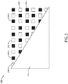
FIG. 3 , an example of the display (e.g., the transmissive touchscreen display 100) ofFIG. 1 is depicted according to the inventive concepts. As shown inFIG. 3 , thebacklight 112 may include two groups of LEDs 208-1, 208-2 that pulse out of phase from one another. An effective pulse frequency of the first group of LEDs 208 pulsing out of phase from the second group of LEDs 208-2 may be at least 100 Hz. A pulse frequency of each of the first group of LEDs 208-1 and the second group of LEDs 208-2 may be between 50 Hz and 100 Hz (e.g., between 50 Hz and 80 Hz). For example, thebacklight 112 with two groups of LEDs 208-1, 208-2, each pulsing at 50 Hz out of phase from one another, may produce half the luminance when compared to a backlight with all LEDs pulsing at 100 Hz. - Referring now to
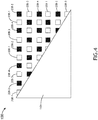
FIG. 4 , an example of the display (e.g., the transmissive touchscreen display 100) ofFIG. 1 is depicted according to the inventive concepts. As shown inFIG. 4 , thebacklight 112 may include four groups of LEDs 208-1, 208-2, 208-3, 280-4 that pulse out of phase from one another. An effective pulse frequency of the first group of LEDs 208-1, the second group of LEDs 208-2, the third group of LEDs 208-3, and the fourth group of LEDs 208-4 pulsing out of phase from one another may be at least 100 Hz. A pulse frequency of each of the four groups of LEDs 208-1, 208-2, 208-3, 208-4 may be between 25 Hz and 100 Hz (e.g., between 25 Hz and 50 Hz). For example, thebacklight 112 with four groups of LEDs 208-1, 208-2 208-3, 208-4, each pulsing at 25 Hz out of phase from one another, may produce 1/4 the luminance when compared to a backlight with all LEDs pulsing at 100 Hz. - For another example of the display (e.g., the transmissive touchscreen display 100), the
backlight 112 may include three groups of LEDs 208-1, 208-2, 208-3 that pulse out of phase from one another. An effective pulse frequency of the first group of LEDs 208-1, the second group of LEDs 208-2, and the third group of LEDs 208-3 pulsing out of phase from one another may be at least 100 Hz. A pulse frequency of each of the three groups of LEDs 208-1, 208-2, 208-3 may be between 33 Hz and 100 Hz (e.g., between 33 Hz and 50 Hz). For example, thebacklight 112 with three groups of LEDs 208-1, 208-2 208-3, each pulsing at 33 Hz out of phase from one another, may produce 1/3 the luminance when compared to a backlight with all LEDs pulsing at 100 Hz. - While examples with two, three, or four groups of LEDs have been disclosed, some examples may include any suitable number (e.g., two, three, four, five, six, ... 10, ... 20, or more) of groups of LEDs. For example, X groups of LEDs may be utilized, and a pulse frequency of each of the X groups of LEDs may be between 100/X Hz and 100 Hz. For example, the
backlight 112 with X groups of LEDs, each pulsing at 100/X Hz out of phase from one another, may produce 1/X the luminance when compared to a backlight with all LEDs pulsing at 100 Hz. - Referring now to
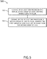
FIG. 5 , amethod 500 according to the inventive concepts disclosed herein may include one or more of the following steps. Additionally, for example, some examples may include performing one more instances of themethod 500 iteratively, concurrently, and/or sequentially. - A
step 502 may include causing, by at least one processor of a display, a first group of light emitting diodes (LEDs) to pulse. - A
step 504 may include causing, by the at least one processor, a second group of LEDs to pulse, wherein the first group of LEDs pulse out of phase from the second group of LEDs. - Further, the
method 500 may include any of the operations disclosed throughout. - As will be appreciated from the above, examples disclosed herein may be directed to a method, system, and display configured to provide a dimming effect to a backlight.
- As used throughout and as would be appreciated by those skilled in the art, "at least one non-transitory computer-readable medium" may refer to as at least one non-transitory computer-readable medium (e.g., memory, storage, or a combination thereof; e.g., at least one computer-readable medium implemented as hardware; e.g., at least one non-transitory processor-readable medium, at least one memory (e.g., at least one nonvolatile memory, at least one volatile memory, or a combination thereof; e.g., at least one random-access memory, at least one flash memory, at least one read-only memory (ROM) (e.g., at least one electrically erasable programmable read-only memory (EEPROM)), at least one on-processor memory (e.g., at least one on-processor cache, at least one on-processor buffer, at least one on-processor flash memory, at least one on-processor EEPROM, or a combination thereof), or a combination thereof), at least one storage device (e.g., at least one hard-disk drive, at least one tape drive, at least one solid-state drive, at least one flash drive, at least one readable and/or writable disk of at least one optical drive configured to read from and/or write to the at least one readable and/or writable disk, or a combination thereof), or a combination thereof).
- As used throughout, "at least one" means one or a plurality of; for example, "at least one" may comprise one, two, three, ..., one hundred, or more. Similarly, as used throughout, "one or more" means one or a plurality of; for example, "one or more" may comprise one, two, three, ..., one hundred, or more. Further, as used throughout, "zero or more" means zero, one, or a plurality of; for example, "zero or more" may comprise zero, one, two, three, ..., one hundred, or more.
- In the present disclosure, the methods, operations, and/or functionality disclosed may be implemented as sets of instructions or software readable by a device. Further, it is understood that the specific order or hierarchy of steps in the methods, operations, and/or functionality disclosed are examples of exemplary approaches. Based upon design preferences, it is understood that the specific order or hierarchy of steps in the methods, operations, and/or functionality can be rearranged while remaining within the scope of the inventive concepts disclosed herein. The accompanying claims may present elements of the various steps in a sample order, and are not necessarily meant to be limited to the specific order or hierarchy presented.
- It is to be understood that examples of the methods disclosed herein may include one or more of the steps described herein. Further, such steps may be carried out in any desired order and two or more of the steps may be carried out simultaneously with one another. Two or more of the steps disclosed herein may be combined in a single step, and in some examples, one or more of the steps may be carried out as two or more sub-steps. Further, other steps or sub-steps may be carried in addition to, or as substitutes to one or more of the steps disclosed herein.
- From the above description, it is clear that the inventive concepts disclosed herein are well adapted to carry out the objects and to attain the advantages mentioned herein as well as those inherent in the inventive concepts disclosed herein. While presently preferred embodiments of the inventive concepts disclosed herein have been described for purposes of this disclosure, it will be understood that numerous changes may be made which will readily suggest themselves to those skilled in the art and which are accomplished within the scope of the invention as defined by the appended claims.
Claims (15)
- A display (100), comprising:
a backlight (112) comprising a plurality of light emitting diodes (LEDs) (208), the plurality of LEDs comprising a first group of LEDs (208-1) and a second group of LEDs (208-2); and
at least one processor (204) communicatively coupled to the plurality of LEDs, wherein the at least one processor is configured to:cause the first group of LEDs to pulse; andcause the second group of LEDs to pulse, wherein the first group of LEDs pulse out of phase from the second group of LEDs. - A system comprising the display (100) of claim 1.
- The system of claim 2, wherein the display (100) is a transmissive display, and/or a touchscreen display.
- The system of claim 2 or 3, wherein the display (100) further comprises a diffuser (110) and a transmissive display element (108), wherein the diffuser is positioned between the backlight (112) and the transmissive display element.
- The system of claim 2, 3 or 4, wherein a user in view of the display (100) perceives a dimming effect based at least on the first group of LEDs (208-1) pulsing out of phase from the second group of LEDs (208-2) as compared to the first group of LEDs and the second group of LEDs pulsing in phase.
- The system of any of claims 2 to 5, further comprising a vehicle, wherein the display is implemented in the vehicle, optionally wherein the vehicle is an aircraft (10).
- The system of any of claims 2 to 6, wherein an effective pulse frequency of the first group of LEDs (208-1) pulsing out of phase from the second group of LEDs (208-2) is at least 100 Hertz (Hz).
- The system of claim 7, wherein a pulse frequency of each of the first group of LEDs (208-1) and the second group of LEDs (208-2) is between 50 Hz and 100 Hz, or between 50 Hz and 80 Hz.
- The system of any of claims 2 to 8, wherein the plurality of LEDs (208) further comprises a third group of LEDs (208-3), wherein the at least one processor (204) is further configured to cause the third group of LEDs to pulse, wherein the first group of LEDs (208-1) pulse out of phase from the second group of LEDs (208-2) and the third group of LEDs (208-3), wherein the second group of LEDs pulse out of phase from the first group of LEDs and the third group of LEDs, wherein the third group of LEDs pulse out of phase from the first group of LEDs and the second group of LEDs.
- The system of claim 9, wherein an effective pulse frequency of the first group of LEDs (208-1), the second group of LEDs (208-2), and the third group of LEDs (208-3) pulsing out of phase from one another is at least 100 Hertz (Hz).
- The system of claim 10, wherein a pulse frequency of each of the first group of LEDs (208-1), the second group of LEDs (208-2), and the third group of LEDs (208-3) is between 33 Hz and 100 Hz, or between 33 Hz and 50 Hz.
- The system of any of claims 2 to 8, wherein the plurality of LEDs further comprises a third group of LEDs (208-3) and a fourth group of LEDs (208-4), wherein the at least one processor (204) is further configured to cause the third group of LEDs to pulse and to cause the fourth group of LEDs to pulse, wherein the first group of LEDs (208-1) pulse out of phase from the second group of LEDs (208-2), the third group of LEDs, and the fourth group of LEDs, wherein the second group of LEDs pulse out of phase from the first group of LEDs, the third group of LEDs, and the fourth group of LEDs, wherein the third group of LEDs pulse out of phase from the first group of LEDs, the second group of LEDs, and the fourth group of LEDs, wherein the fourth group of LEDs pulse out of phase from the first group of LEDs, the second group of LEDs, and the third group of LEDs.
- The system of claim 12, wherein an effective pulse frequency of the first group of LEDs (208-1), the second group of LEDs (208-2), the third group of LEDs (208-3), and the fourth group of LEDs (208-4) pulsing out of phase from one another is at least 100 Hertz (Hz).
- The system of claim 13, wherein a pulse frequency of each of the first group of LEDs (208-1), the second group of LEDs (208-2), the third group of LEDs (208-3), and the fourth group of LEDs (208-4) is between 25 Hz and 100 Hz, or between 25 Hz and 50 Hz.
- A method (500), comprising:
causing, by at least one processor (204) of a display (100), a first group of light emitting diodes (LEDs) (208-1) to pulse, wherein the display comprises a backlight (112) and the at least one processor, wherein the backlight comprises a plurality of LEDs, the plurality of LEDs comprising the first group of LEDs and a second group of LEDs (208-2), wherein the at least one processor is communicatively coupled to the plurality of LEDs; and
causing, by the at least one processor, the second group of LEDs to pulse, wherein the first group of LEDs pulse out of phase from the second group of LEDs.
Applications Claiming Priority (1)
| Application Number | Priority Date | Filing Date | Title |
|---|---|---|---|
| US16/529,302 US11102860B2 (en) | 2019-08-01 | 2019-08-01 | Backlit display dimming system and method |
Publications (2)
| Publication Number | Publication Date |
|---|---|
| EP3772056A1 true EP3772056A1 (en) | 2021-02-03 |
| EP3772056B1 EP3772056B1 (en) | 2025-08-20 |
Family
ID=68916433
Family Applications (1)
| Application Number | Title | Priority Date | Filing Date |
|---|---|---|---|
| EP19216066.1A Active EP3772056B1 (en) | 2019-08-01 | 2019-12-13 | Backlit display dimming system and method |
Country Status (2)
| Country | Link |
|---|---|
| US (1) | US11102860B2 (en) |
| EP (1) | EP3772056B1 (en) |
Families Citing this family (2)
| Publication number | Priority date | Publication date | Assignee | Title |
|---|---|---|---|---|
| US12601865B2 (en) | 2023-07-06 | 2026-04-14 | Rockwell Collins, Inc. | Split NVIS filter design |
| US12620709B2 (en) | 2023-07-19 | 2026-05-05 | Rockwell Colins, Inc. | Full-duplex circular parasitic array assembly |
Citations (2)
| Publication number | Priority date | Publication date | Assignee | Title |
|---|---|---|---|---|
| US7002546B1 (en) * | 2002-05-15 | 2006-02-21 | Rockwell Collins, Inc. | Luminance and chromaticity control of an LCD backlight |
| US20140306873A1 (en) * | 2013-04-11 | 2014-10-16 | Funai Electric Co., Ltd. | Backlight apparatus and display apparatus |
Family Cites Families (16)
| Publication number | Priority date | Publication date | Assignee | Title |
|---|---|---|---|---|
| US3885682A (en) | 1972-11-13 | 1975-05-27 | Joseph E Mcwilliams | Mail bag handling apparatus |
| NL1028534C1 (en) | 2005-03-14 | 2006-09-18 | Vanderlande Ind Nederland | Luggage pieces moving vehicle for aeroplane, has bridging conveyor system with bridging conveyor and guide system for extending conveyor from vehicle into aeroplane by guide system |
| US20090225020A1 (en) * | 2008-03-07 | 2009-09-10 | O2Micro, Inc. | Backlight controller for driving light sources |
| US8184230B2 (en) * | 2009-05-08 | 2012-05-22 | Honeywell International Inc. | High efficiency backlight assembly for flat panel display assembly and method for the manufacture thereof |
| US8907884B2 (en) * | 2010-01-06 | 2014-12-09 | Apple Inc. | LED backlight system |
| JP4922439B2 (en) * | 2010-07-01 | 2012-04-25 | シャープ株式会社 | LED control device, liquid crystal display device |
| JP2012108494A (en) * | 2010-10-25 | 2012-06-07 | Semiconductor Energy Lab Co Ltd | Display device |
| US8464859B2 (en) | 2010-10-26 | 2013-06-18 | Engineered Lifting Systems & Equipment Inc. | Conveyor apparatus for unloading packages from shipping containers |
| US20130328866A1 (en) * | 2010-11-19 | 2013-12-12 | Reald Inc. | Spatially multiplexed imaging directional backlight displays |
| EP2772440B1 (en) | 2013-02-27 | 2015-07-22 | Vanderlande Industries B.V. | Device and method for handling items of luggage |
| JP2018509359A (en) | 2015-03-24 | 2018-04-05 | ハート、ジョン イー.HART, John E. | Loading system |
| WO2016210126A1 (en) | 2015-06-24 | 2016-12-29 | Hds Mercury, Inc. | Mobile robot loader-unloader system and method |
| JP6732633B2 (en) * | 2016-11-07 | 2020-07-29 | 株式会社ジャパンディスプレイ | Electronic devices and display devices |
| JP2018124458A (en) * | 2017-02-01 | 2018-08-09 | パナソニック液晶ディスプレイ株式会社 | Liquid crystal backlight device and display device |
| US10429641B2 (en) * | 2017-05-31 | 2019-10-01 | GM Global Technology Operations LLC | Light-enhanced self-cleaning film system and method of forming same |
| US10971086B2 (en) * | 2018-02-02 | 2021-04-06 | Apple Inc. | Pulsed backlight systems and methods |
-
2019
- 2019-08-01 US US16/529,302 patent/US11102860B2/en active Active
- 2019-12-13 EP EP19216066.1A patent/EP3772056B1/en active Active
Patent Citations (2)
| Publication number | Priority date | Publication date | Assignee | Title |
|---|---|---|---|---|
| US7002546B1 (en) * | 2002-05-15 | 2006-02-21 | Rockwell Collins, Inc. | Luminance and chromaticity control of an LCD backlight |
| US20140306873A1 (en) * | 2013-04-11 | 2014-10-16 | Funai Electric Co., Ltd. | Backlight apparatus and display apparatus |
Also Published As
| Publication number | Publication date |
|---|---|
| US20210037621A1 (en) | 2021-02-04 |
| EP3772056B1 (en) | 2025-08-20 |
| US11102860B2 (en) | 2021-08-24 |
Similar Documents
| Publication | Publication Date | Title |
|---|---|---|
| US9709847B2 (en) | Liquid crystal display backlight | |
| US11308896B2 (en) | Liquid crystal display device and control method thereof, head-mounted display apparatus and medium | |
| US9076357B2 (en) | Redundant operation of a backlight unit of a display device under a shorted LED condition | |
| US9899001B2 (en) | Display panel, display device having the same, and controlling method thereof | |
| US9271379B2 (en) | Redundant operation of a backlight unit of a display device under open circuit or short circuit LED string conditions | |
| US8654068B2 (en) | Enhanced resolution of luminance levels in a backlight unit of a display device | |
| JP6154030B2 (en) | Ambient light recognition display device | |
| US20140247295A1 (en) | Redundant operation of a backlight unit of a display device under open circuit or short circuit led string conditions and including dynamic phase shifting between led strings | |
| EP3772056B1 (en) | Backlit display dimming system and method | |
| US20160195772A1 (en) | Liquid crystal display | |
| US9386637B2 (en) | Device and method for time multiplexing switchable optical elements for controllable lighting | |
| CN111243520B (en) | Brightness adjusting method, brightness adjusting device and OLED display | |
| US10957247B1 (en) | Display with sub-pixel drive | |
| US9842569B2 (en) | Display device capable of gradually changing luminance and gamma | |
| US10068515B2 (en) | Display device | |
| US20170311403A1 (en) | System for adaptive non-linear light dimming of electro-optical devices | |
| US10859879B2 (en) | Liquid crystal grating and driving method thereof, display device | |
| JP2016518618A (en) | Display device configured for selective illumination of image subframes | |
| US20180107008A1 (en) | 3d display apparatus and method for driving the 3d display apparatus | |
| US7821474B2 (en) | Rendering luminance levels of a high dynamic range display | |
| KR101041354B1 (en) | LCD panel with scanning backlight | |
| US20170221431A1 (en) | Display panel, display device and display control method | |
| US20140340420A1 (en) | Hybrid display device and displaying method thereof | |
| CA2633864A1 (en) | Display device having a plurality of pixels and method for displaying images | |
| US10319289B2 (en) | Method for generating dimming signal of light emitting diode display device |
Legal Events
| Date | Code | Title | Description |
|---|---|---|---|
| PUAI | Public reference made under article 153(3) epc to a published international application that has entered the european phase |
Free format text: ORIGINAL CODE: 0009012 |
|
| STAA | Information on the status of an ep patent application or granted ep patent |
Free format text: STATUS: THE APPLICATION HAS BEEN PUBLISHED |
|
| AK | Designated contracting states |
Kind code of ref document: A1 Designated state(s): AL AT BE BG CH CY CZ DE DK EE ES FI FR GB GR HR HU IE IS IT LI LT LU LV MC MK MT NL NO PL PT RO RS SE SI SK SM TR |
|
| AX | Request for extension of the european patent |
Extension state: BA ME |
|
| STAA | Information on the status of an ep patent application or granted ep patent |
Free format text: STATUS: REQUEST FOR EXAMINATION WAS MADE |
|
| 17P | Request for examination filed |
Effective date: 20210803 |
|
| RBV | Designated contracting states (corrected) |
Designated state(s): AL AT BE BG CH CY CZ DE DK EE ES FI FR GB GR HR HU IE IS IT LI LT LU LV MC MK MT NL NO PL PT RO RS SE SI SK SM TR |
|
| STAA | Information on the status of an ep patent application or granted ep patent |
Free format text: STATUS: EXAMINATION IS IN PROGRESS |
|
| 17Q | First examination report despatched |
Effective date: 20230406 |
|
| GRAP | Despatch of communication of intention to grant a patent |
Free format text: ORIGINAL CODE: EPIDOSNIGR1 |
|
| STAA | Information on the status of an ep patent application or granted ep patent |
Free format text: STATUS: GRANT OF PATENT IS INTENDED |
|
| INTG | Intention to grant announced |
Effective date: 20250514 |
|
| GRAS | Grant fee paid |
Free format text: ORIGINAL CODE: EPIDOSNIGR3 |
|
| GRAA | (expected) grant |
Free format text: ORIGINAL CODE: 0009210 |
|
| STAA | Information on the status of an ep patent application or granted ep patent |
Free format text: STATUS: THE PATENT HAS BEEN GRANTED |
|
| AK | Designated contracting states |
Kind code of ref document: B1 Designated state(s): AL AT BE BG CH CY CZ DE DK EE ES FI FR GB GR HR HU IE IS IT LI LT LU LV MC MK MT NL NO PL PT RO RS SE SI SK SM TR |
|
| REG | Reference to a national code |
Ref country code: GB Ref legal event code: FG4D |
|
| REG | Reference to a national code |
Ref country code: CH Ref legal event code: EP |
|
| REG | Reference to a national code |
Ref country code: DE Ref legal event code: R096 Ref document number: 602019074351 Country of ref document: DE |
|
| REG | Reference to a national code |
Ref country code: IE Ref legal event code: FG4D |
|
| REG | Reference to a national code |
Ref country code: NL Ref legal event code: MP Effective date: 20250820 |
|
| PG25 | Lapsed in a contracting state [announced via postgrant information from national office to epo] |
Ref country code: IS Free format text: LAPSE BECAUSE OF FAILURE TO SUBMIT A TRANSLATION OF THE DESCRIPTION OR TO PAY THE FEE WITHIN THE PRESCRIBED TIME-LIMIT Effective date: 20251220 |
|
| PGFP | Annual fee paid to national office [announced via postgrant information from national office to epo] |
Ref country code: DE Payment date: 20251126 Year of fee payment: 7 |
|
| PGFP | Annual fee paid to national office [announced via postgrant information from national office to epo] |
Ref country code: GB Payment date: 20251120 Year of fee payment: 7 |
|
| PG25 | Lapsed in a contracting state [announced via postgrant information from national office to epo] |
Ref country code: NO Free format text: LAPSE BECAUSE OF FAILURE TO SUBMIT A TRANSLATION OF THE DESCRIPTION OR TO PAY THE FEE WITHIN THE PRESCRIBED TIME-LIMIT Effective date: 20251120 |
|
| REG | Reference to a national code |
Ref country code: LT Ref legal event code: MG9D |
|
| PG25 | Lapsed in a contracting state [announced via postgrant information from national office to epo] |
Ref country code: PT Free format text: LAPSE BECAUSE OF FAILURE TO SUBMIT A TRANSLATION OF THE DESCRIPTION OR TO PAY THE FEE WITHIN THE PRESCRIBED TIME-LIMIT Effective date: 20251222 |
|
| PG25 | Lapsed in a contracting state [announced via postgrant information from national office to epo] |
Ref country code: FI Free format text: LAPSE BECAUSE OF FAILURE TO SUBMIT A TRANSLATION OF THE DESCRIPTION OR TO PAY THE FEE WITHIN THE PRESCRIBED TIME-LIMIT Effective date: 20250820 |
|
| PG25 | Lapsed in a contracting state [announced via postgrant information from national office to epo] |
Ref country code: HR Free format text: LAPSE BECAUSE OF FAILURE TO SUBMIT A TRANSLATION OF THE DESCRIPTION OR TO PAY THE FEE WITHIN THE PRESCRIBED TIME-LIMIT Effective date: 20250820 Ref country code: NL Free format text: LAPSE BECAUSE OF FAILURE TO SUBMIT A TRANSLATION OF THE DESCRIPTION OR TO PAY THE FEE WITHIN THE PRESCRIBED TIME-LIMIT Effective date: 20250820 |
|
| PGFP | Annual fee paid to national office [announced via postgrant information from national office to epo] |
Ref country code: FR Payment date: 20251120 Year of fee payment: 7 |
|
| PG25 | Lapsed in a contracting state [announced via postgrant information from national office to epo] |
Ref country code: GR Free format text: LAPSE BECAUSE OF FAILURE TO SUBMIT A TRANSLATION OF THE DESCRIPTION OR TO PAY THE FEE WITHIN THE PRESCRIBED TIME-LIMIT Effective date: 20251121 |
|
| PG25 | Lapsed in a contracting state [announced via postgrant information from national office to epo] |
Ref country code: SE Free format text: LAPSE BECAUSE OF FAILURE TO SUBMIT A TRANSLATION OF THE DESCRIPTION OR TO PAY THE FEE WITHIN THE PRESCRIBED TIME-LIMIT Effective date: 20250820 |
|
| PG25 | Lapsed in a contracting state [announced via postgrant information from national office to epo] |
Ref country code: LV Free format text: LAPSE BECAUSE OF FAILURE TO SUBMIT A TRANSLATION OF THE DESCRIPTION OR TO PAY THE FEE WITHIN THE PRESCRIBED TIME-LIMIT Effective date: 20250820 |
|
| PG25 | Lapsed in a contracting state [announced via postgrant information from national office to epo] |
Ref country code: BG Free format text: LAPSE BECAUSE OF FAILURE TO SUBMIT A TRANSLATION OF THE DESCRIPTION OR TO PAY THE FEE WITHIN THE PRESCRIBED TIME-LIMIT Effective date: 20250820 Ref country code: PL Free format text: LAPSE BECAUSE OF FAILURE TO SUBMIT A TRANSLATION OF THE DESCRIPTION OR TO PAY THE FEE WITHIN THE PRESCRIBED TIME-LIMIT Effective date: 20250820 |
|
| PG25 | Lapsed in a contracting state [announced via postgrant information from national office to epo] |
Ref country code: RS Free format text: LAPSE BECAUSE OF FAILURE TO SUBMIT A TRANSLATION OF THE DESCRIPTION OR TO PAY THE FEE WITHIN THE PRESCRIBED TIME-LIMIT Effective date: 20251120 |
|
| PG25 | Lapsed in a contracting state [announced via postgrant information from national office to epo] |
Ref country code: ES Free format text: LAPSE BECAUSE OF FAILURE TO SUBMIT A TRANSLATION OF THE DESCRIPTION OR TO PAY THE FEE WITHIN THE PRESCRIBED TIME-LIMIT Effective date: 20250820 |
|
| REG | Reference to a national code |
Ref country code: AT Ref legal event code: MK05 Ref document number: 1828210 Country of ref document: AT Kind code of ref document: T Effective date: 20250820 |
|
| PG25 | Lapsed in a contracting state [announced via postgrant information from national office to epo] |
Ref country code: RO Free format text: LAPSE BECAUSE OF FAILURE TO SUBMIT A TRANSLATION OF THE DESCRIPTION OR TO PAY THE FEE WITHIN THE PRESCRIBED TIME-LIMIT Effective date: 20250820 |
|
| PG25 | Lapsed in a contracting state [announced via postgrant information from national office to epo] |
Ref country code: SM Free format text: LAPSE BECAUSE OF FAILURE TO SUBMIT A TRANSLATION OF THE DESCRIPTION OR TO PAY THE FEE WITHIN THE PRESCRIBED TIME-LIMIT Effective date: 20250820 |
|
| PG25 | Lapsed in a contracting state [announced via postgrant information from national office to epo] |
Ref country code: DK Free format text: LAPSE BECAUSE OF FAILURE TO SUBMIT A TRANSLATION OF THE DESCRIPTION OR TO PAY THE FEE WITHIN THE PRESCRIBED TIME-LIMIT Effective date: 20250820 |
|
| PG25 | Lapsed in a contracting state [announced via postgrant information from national office to epo] |
Ref country code: AT Free format text: LAPSE BECAUSE OF FAILURE TO SUBMIT A TRANSLATION OF THE DESCRIPTION OR TO PAY THE FEE WITHIN THE PRESCRIBED TIME-LIMIT Effective date: 20250820 |
|
| PG25 | Lapsed in a contracting state [announced via postgrant information from national office to epo] |
Ref country code: IT Free format text: LAPSE BECAUSE OF FAILURE TO SUBMIT A TRANSLATION OF THE DESCRIPTION OR TO PAY THE FEE WITHIN THE PRESCRIBED TIME-LIMIT Effective date: 20250820 |
|
| PG25 | Lapsed in a contracting state [announced via postgrant information from national office to epo] |
Ref country code: CZ Free format text: LAPSE BECAUSE OF FAILURE TO SUBMIT A TRANSLATION OF THE DESCRIPTION OR TO PAY THE FEE WITHIN THE PRESCRIBED TIME-LIMIT Effective date: 20250820 |
|
| PG25 | Lapsed in a contracting state [announced via postgrant information from national office to epo] |
Ref country code: SK Free format text: LAPSE BECAUSE OF FAILURE TO SUBMIT A TRANSLATION OF THE DESCRIPTION OR TO PAY THE FEE WITHIN THE PRESCRIBED TIME-LIMIT Effective date: 20250820 Ref country code: EE Free format text: LAPSE BECAUSE OF FAILURE TO SUBMIT A TRANSLATION OF THE DESCRIPTION OR TO PAY THE FEE WITHIN THE PRESCRIBED TIME-LIMIT Effective date: 20250820 |