EP3771832A1 - Motor and bearing cooling paths - Google Patents
Motor and bearing cooling paths Download PDFInfo
- Publication number
- EP3771832A1 EP3771832A1 EP19215038.1A EP19215038A EP3771832A1 EP 3771832 A1 EP3771832 A1 EP 3771832A1 EP 19215038 A EP19215038 A EP 19215038A EP 3771832 A1 EP3771832 A1 EP 3771832A1
- Authority
- EP
- European Patent Office
- Prior art keywords
- bearing
- compressor
- cooling air
- motor
- shaft
- Prior art date
- Legal status (The legal status is an assumption and is not a legal conclusion. Google has not performed a legal analysis and makes no representation as to the accuracy of the status listed.)
- Pending
Links
- 238000001816 cooling Methods 0.000 title claims abstract description 96
- 238000011144 upstream manufacturing Methods 0.000 claims abstract description 14
- 238000000034 method Methods 0.000 claims abstract description 9
- 238000004891 communication Methods 0.000 claims description 10
- 239000012530 fluid Substances 0.000 claims description 10
- 238000009413 insulation Methods 0.000 description 1
- 238000012986 modification Methods 0.000 description 1
- 230000004048 modification Effects 0.000 description 1
- 229920003223 poly(pyromellitimide-1,4-diphenyl ether) Polymers 0.000 description 1
- 230000003068 static effect Effects 0.000 description 1
Images


Classifications
-
- F—MECHANICAL ENGINEERING; LIGHTING; HEATING; WEAPONS; BLASTING
- F04—POSITIVE - DISPLACEMENT MACHINES FOR LIQUIDS; PUMPS FOR LIQUIDS OR ELASTIC FLUIDS
- F04D—NON-POSITIVE-DISPLACEMENT PUMPS
- F04D29/00—Details, component parts, or accessories
- F04D29/58—Cooling; Heating; Diminishing heat transfer
- F04D29/582—Cooling; Heating; Diminishing heat transfer specially adapted for elastic fluid pumps
- F04D29/584—Cooling; Heating; Diminishing heat transfer specially adapted for elastic fluid pumps cooling or heating the machine
-
- F—MECHANICAL ENGINEERING; LIGHTING; HEATING; WEAPONS; BLASTING
- F04—POSITIVE - DISPLACEMENT MACHINES FOR LIQUIDS; PUMPS FOR LIQUIDS OR ELASTIC FLUIDS
- F04D—NON-POSITIVE-DISPLACEMENT PUMPS
- F04D29/00—Details, component parts, or accessories
- F04D29/05—Shafts or bearings, or assemblies thereof, specially adapted for elastic fluid pumps
- F04D29/056—Bearings
-
- F—MECHANICAL ENGINEERING; LIGHTING; HEATING; WEAPONS; BLASTING
- F04—POSITIVE - DISPLACEMENT MACHINES FOR LIQUIDS; PUMPS FOR LIQUIDS OR ELASTIC FLUIDS
- F04D—NON-POSITIVE-DISPLACEMENT PUMPS
- F04D17/00—Radial-flow pumps, e.g. centrifugal pumps; Helico-centrifugal pumps
- F04D17/08—Centrifugal pumps
- F04D17/10—Centrifugal pumps for compressing or evacuating
-
- F—MECHANICAL ENGINEERING; LIGHTING; HEATING; WEAPONS; BLASTING
- F04—POSITIVE - DISPLACEMENT MACHINES FOR LIQUIDS; PUMPS FOR LIQUIDS OR ELASTIC FLUIDS
- F04D—NON-POSITIVE-DISPLACEMENT PUMPS
- F04D25/00—Pumping installations or systems
- F04D25/02—Units comprising pumps and their driving means
- F04D25/06—Units comprising pumps and their driving means the pump being electrically driven
-
- F—MECHANICAL ENGINEERING; LIGHTING; HEATING; WEAPONS; BLASTING
- F04—POSITIVE - DISPLACEMENT MACHINES FOR LIQUIDS; PUMPS FOR LIQUIDS OR ELASTIC FLUIDS
- F04D—NON-POSITIVE-DISPLACEMENT PUMPS
- F04D25/00—Pumping installations or systems
- F04D25/02—Units comprising pumps and their driving means
- F04D25/06—Units comprising pumps and their driving means the pump being electrically driven
- F04D25/0606—Units comprising pumps and their driving means the pump being electrically driven the electric motor being specially adapted for integration in the pump
-
- F—MECHANICAL ENGINEERING; LIGHTING; HEATING; WEAPONS; BLASTING
- F04—POSITIVE - DISPLACEMENT MACHINES FOR LIQUIDS; PUMPS FOR LIQUIDS OR ELASTIC FLUIDS
- F04D—NON-POSITIVE-DISPLACEMENT PUMPS
- F04D25/00—Pumping installations or systems
- F04D25/02—Units comprising pumps and their driving means
- F04D25/08—Units comprising pumps and their driving means the working fluid being air, e.g. for ventilation
- F04D25/082—Units comprising pumps and their driving means the working fluid being air, e.g. for ventilation the unit having provision for cooling the motor
-
- F—MECHANICAL ENGINEERING; LIGHTING; HEATING; WEAPONS; BLASTING
- F04—POSITIVE - DISPLACEMENT MACHINES FOR LIQUIDS; PUMPS FOR LIQUIDS OR ELASTIC FLUIDS
- F04D—NON-POSITIVE-DISPLACEMENT PUMPS
- F04D29/00—Details, component parts, or accessories
- F04D29/05—Shafts or bearings, or assemblies thereof, specially adapted for elastic fluid pumps
- F04D29/051—Axial thrust balancing
-
- F—MECHANICAL ENGINEERING; LIGHTING; HEATING; WEAPONS; BLASTING
- F04—POSITIVE - DISPLACEMENT MACHINES FOR LIQUIDS; PUMPS FOR LIQUIDS OR ELASTIC FLUIDS
- F04D—NON-POSITIVE-DISPLACEMENT PUMPS
- F04D29/00—Details, component parts, or accessories
- F04D29/58—Cooling; Heating; Diminishing heat transfer
- F04D29/5806—Cooling the drive system
-
- F—MECHANICAL ENGINEERING; LIGHTING; HEATING; WEAPONS; BLASTING
- F16—ENGINEERING ELEMENTS AND UNITS; GENERAL MEASURES FOR PRODUCING AND MAINTAINING EFFECTIVE FUNCTIONING OF MACHINES OR INSTALLATIONS; THERMAL INSULATION IN GENERAL
- F16C—SHAFTS; FLEXIBLE SHAFTS; ELEMENTS OR CRANKSHAFT MECHANISMS; ROTARY BODIES OTHER THAN GEARING ELEMENTS; BEARINGS
- F16C37/00—Cooling of bearings
-
- H—ELECTRICITY
- H02—GENERATION; CONVERSION OR DISTRIBUTION OF ELECTRIC POWER
- H02K—DYNAMO-ELECTRIC MACHINES
- H02K5/00—Casings; Enclosures; Supports
- H02K5/04—Casings or enclosures characterised by the shape, form or construction thereof
- H02K5/16—Means for supporting bearings, e.g. insulating supports or means for fitting bearings in the bearing-shields
- H02K5/167—Means for supporting bearings, e.g. insulating supports or means for fitting bearings in the bearing-shields using sliding-contact or spherical cap bearings
- H02K5/1672—Means for supporting bearings, e.g. insulating supports or means for fitting bearings in the bearing-shields using sliding-contact or spherical cap bearings radially supporting the rotary shaft at both ends of the rotor
-
- H—ELECTRICITY
- H02—GENERATION; CONVERSION OR DISTRIBUTION OF ELECTRIC POWER
- H02K—DYNAMO-ELECTRIC MACHINES
- H02K5/00—Casings; Enclosures; Supports
- H02K5/04—Casings or enclosures characterised by the shape, form or construction thereof
- H02K5/20—Casings or enclosures characterised by the shape, form or construction thereof with channels or ducts for flow of cooling medium
-
- H—ELECTRICITY
- H02—GENERATION; CONVERSION OR DISTRIBUTION OF ELECTRIC POWER
- H02K—DYNAMO-ELECTRIC MACHINES
- H02K7/00—Arrangements for handling mechanical energy structurally associated with dynamo-electric machines, e.g. structural association with mechanical driving motors or auxiliary dynamo-electric machines
- H02K7/08—Structural association with bearings
- H02K7/083—Structural association with bearings radially supporting the rotary shaft at both ends of the rotor
-
- H—ELECTRICITY
- H02—GENERATION; CONVERSION OR DISTRIBUTION OF ELECTRIC POWER
- H02K—DYNAMO-ELECTRIC MACHINES
- H02K9/00—Arrangements for cooling or ventilating
- H02K9/10—Arrangements for cooling or ventilating by gaseous cooling medium flowing in closed circuit, a part of which is external to the machine casing
-
- F—MECHANICAL ENGINEERING; LIGHTING; HEATING; WEAPONS; BLASTING
- F04—POSITIVE - DISPLACEMENT MACHINES FOR LIQUIDS; PUMPS FOR LIQUIDS OR ELASTIC FLUIDS
- F04D—NON-POSITIVE-DISPLACEMENT PUMPS
- F04D29/00—Details, component parts, or accessories
- F04D29/05—Shafts or bearings, or assemblies thereof, specially adapted for elastic fluid pumps
- F04D29/056—Bearings
- F04D29/057—Bearings hydrostatic; hydrodynamic
-
- F—MECHANICAL ENGINEERING; LIGHTING; HEATING; WEAPONS; BLASTING
- F16—ENGINEERING ELEMENTS AND UNITS; GENERAL MEASURES FOR PRODUCING AND MAINTAINING EFFECTIVE FUNCTIONING OF MACHINES OR INSTALLATIONS; THERMAL INSULATION IN GENERAL
- F16C—SHAFTS; FLEXIBLE SHAFTS; ELEMENTS OR CRANKSHAFT MECHANISMS; ROTARY BODIES OTHER THAN GEARING ELEMENTS; BEARINGS
- F16C2360/00—Engines or pumps
-
- H—ELECTRICITY
- H02—GENERATION; CONVERSION OR DISTRIBUTION OF ELECTRIC POWER
- H02K—DYNAMO-ELECTRIC MACHINES
- H02K2205/00—Specific aspects not provided for in the other groups of this subclass relating to casings, enclosures, supports
- H02K2205/03—Machines characterised by thrust bearings
Definitions
- This application relates to a compressor for an air machine.
- Air machines include a turbine and a compressor. Partially compressed air is delivered to the compressor, and the compressor is driven to further compress this air. A motor drives the compressor. This compressed air is passed downstream to drive a turbine, with the turbine in turn helping to drive the compressor as the air expands across the turbine. This expanded air is then utilized for a downstream use, such as cabin air for an aircraft.
- Air machines have a shaft which connects the compressor and the turbine. Bearings facilitate rotation of the shaft. Heat accumulates in the compressor as the air machine operates, and in particular, at the bearings and motor.
- a compressor includes a rotor configured to compress air and driven by a shaft.
- a motor is drives the shaft.
- First and second journal bearings facilitate rotation of the shaft.
- the first journal bearing is upstream from the motor and the second journal bearing is downstream from the motor.
- a transfer tube is configured to provide cooling air from a bearing cooling air inlet to the second journal bearing.
- the cooling air travels in the same direction through the first journal bearing as a direction of airflow through the compressor.
- a thrust bearing is configured to facilitate rotation of the shaft.
- the thrust bearing is arranged downstream from the second journal bearing, and wherein the bearing cooling air inlet is in fluid communication with the thrust bearing.
- the thrust bearing includes a thrust shaft and a thrust plate, the thrust shaft including first and second orifices.
- the first and second orifices are in fluid communication with the bearing cooling air inlet.
- the second journal bearing is in fluid communication with the second orifice and the thrust bearing is in fluid communication with the first orifice.
- the compressor includes a passage between the motor and the shaft.
- the passage is in fluid communication with the bearing cooling air inlet via the first and second orifices.
- the bearing cooling stream includes first and second bearing cooling streams.
- the first bearing cooling stream passes through the first journal bearing and the second bearing cooling stream does not pass through the first journal bearing.
- a seal is immediately upstream from the first journal bearing and is configured to direct the second bearing cooling stream to the motor.
- the motor includes a motor rotor shaft.
- the motor rotor shaft includes an orifice upstream from the motor.
- the orifice is configured to communicate the cooling air to a cooling air outlet.
- a heat shield is upstream from the motor.
- the transfer tube is attached to a housing of the motor.
- a method for cooling a compressor includes providing a first cooling air stream to a thrust bearing and a first journal bearing.
- the thrust bearing and first journal bearings are configured to facilitate rotation of a shaft in a compressor.
- a second cooling air stream is provided to a second journal bearing such that that cooling air provided to the second journal bearing does not pass through the first journal bearing.
- the second cooling air stream is provided to the second journal bearing from a bearing cooling air inlet via a transfer tube.
- the second cooling air stream flows through the second journal bearing in the same direction as a direction of airflow through the compressor.
- the thrust bearing includes a thrust shaft and a thrust plate, the thrust shaft includes first and second orifices. The first cooling air stream flows through the orifices.
- the method provides the first cooling air stream to a motor which is configured to rotate the shaft.
- the method expels the first cooling air stream from the compressor after providing the first cooling air stream passes to the motor and expelling the second cooling air stream after providing the second cooling air stream to the second journal bearing.
- Figure 1 shows a compressor 20 that may be incorporated into a cabin air supply system 21 for supplying air to the cabin of an aircraft.
- a rotor 22 receives air to be compressed from an inlet 24, and compresses the air to a compressor outlet 26.
- a motor 28 drives a motor rotor shaft 39 and driveshaft 30 and to rotate the rotor 22.
- the motor 28 is an electric motor and includes a rotor 31 and a stator 32, as would be known in the art.
- a thrust bearing 33 and a journal bearings 34a, 34b facilitate rotation of the driveshaft 30.
- the thrust bearing 33 includes a thrust bearing disk 36 which is associated with a thrust shaft 38.
- the thrust shaft 38 connects to the motor rotor shaft 39.
- the thrust bearing disk 36 has thrust bearing surfaces 40.
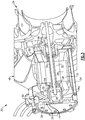
- FIG. 1 schematically shows a detail view of the motor 28 and bearing 33, 34a, 34b.
- Figure 3 shows an isometric view of the compressor of Figure 1 .
- a motor cooling stream MC is drawn from the compressor inlet 20 at 42 and provided to a motor cooling inlet 44.
- the motor cooling stream MC ultimately exits the compressor 20 via a cooing air outlet 48.
- the outlet 48 ducts to ram (e.g., ambient) air.
- a bearing cooling stream BC is drawn from downstream of the compressor outlet 26 and provided to a bearing cooling inlet 50.
- a heat exchanger (not shown) is upstream from the bearing cooling inlet 50 and downstream from the compressor outlet 26, and cools air in the bearing cooling stream BC.
- the bearing cooling stream BC cools the thrust bearing 33 and the journal bearings 34a, 34b, and provides cooling to the motor 28, will be explained in more detail below.
- the bearing cooling stream BC is split into two bearing cooling streams BC1 and BC2, which pass along either side of the thrust bearing disk 36 at thrust surfaces 40 to cool the thrust bearing 33.
- the bearing cooling streams BC1 and BC2 continue along either side of the thrust shaft 38.
- Orifices O1 and O2 are formed in the thrust shaft 38.
- the orifice 01 is oriented generally parallel to an axis A of the shaft 30 while the orifice O2 is oriented generally perpendicular to an axis A of the shaft 30. That is, the orifices 01, 02 are oriented generally perpendicular to one another.
- the first bearing cooling stream B1 passes through the journal bearing 34a and then through the orifice O2.
- the second bearing cooling stream BC2 passes through the orifice 01.
- the first bearing cooling stream BC1 then joins the second bearing cooling stream BC2 and both streams pass along the inside diameter of the motor 28, via a passage 45 adjacent the driveshaft 30, providing cooling to the motor 28 and/or driveshaft 30.
- the bearing cooling stream BC then passes through an orifice O3 formed in the motor rotor shaft 39 upstream of the motor 28, and exits the compressor 20 via a cooling air outlet 48.
- the outlet 48 ducts to ram (e.g., ambient) air.
- a third bearing cooling stream BC3 is also provided from the bearing cooling air inlet 50 to a transfer tube 54.
- the transfer tube 54 communicates the bearing cooling stream BC3 to the journal bearing 34b.
- the transfer tube 54 is attached to a housing 56 of the motor 28 via bosses 57.
- Bearing cooling stream BC3 is provided to the journal bearing 34b via an opening 35 in a bearing support 66 (discussed more below) and passes through the journal bearing 34b in the same direction as the direction of airflow through the compressor 20.
- the third bearing cooling stream BC3 does not pass through the thrust bearing 33 or journal bearing 34a. Accordingly, the third bearing cooling stream BC3 is relatively cool compared to the first and second bearing cooling streams BC1, BC2 at the orifice O3. Therefore, the third bearing cooling stream BC3 provides improved cooling to the journal bearing 34a as compared to a cooling stream that has passed through the thrust bearing 33 and/or journal bearing 34a, or another compressor 20 component.
- the third bearing cooling stream BC3 exits the compressor 20 via cooling air outlet 48.
- a seal 59 such as a labyrinth seal (though other types of seals are contemplated), is arranged immediately upstream from the journal bearing 34a and downstream from the motor 28.
- the seal 59 prevents the first bearing cooling stream BC1 from entering a cavity 58 between the thrust bearing 33 and the motor 28.
- the first bearing cooling stream BC1 is directed into the orifice O2 and then into the motor 28 (as discussed above) by the seal 59.
- Air in the cavity 58 therefore stays cool relative to the temperature of air in the first bearing cooling stream BC1, and provides thermal insulation for the motor 28 and other compressor 20 components from the relatively hot first bearing cooling stream BC1.
- the seal 59 prevents loss of pressure in the first bearing cooling stream BC1 as it travels through journal bearing 34a. In other words, the pressure drop of the first bearing cooling stream BC1 across the journal bearing 34a is relatively low. This improves the lifetime and reliability of the journal bearing 34a.
- a heat shield 60 and seal plate 62 are provided upstream from the motor 28 and adjacent the journal bearing 34b.
- the seal plate 62 includes a seal 64 such as a vespel seal or o-seal, though other types of seals are contemplated.
- seal 64 is a static o-seal. Seal 64 prevents high-pressure air in the third bearing cooling stream BC3 from leaking into the outlet 48 prior to entering the journal bearing 34b. In other words, the seal 64 helps direct bearing cooling stream BC3 into the journal bearing 34b.
- the seal plate 62 also includes a seal 65 such as a labyrinth seal (though other types of seals are contemplated) immediately downstream from the journal bearing 34b. As with the seal 59 adjacent the journal bearing 34a, the seals 64, 65 adjacent the journal bearing 34b maintain pressure in the journal bearing 34b to minimize pressure drop across the journal bearing 34b, which improves the lifetime and reliability of the journal bearing 34b.
- the heat shield 60 and seal 64 are downstream from a bearing support 66, while the seal plate 62 and seal 65 are upstream of the bearing support 66.
- the bearing support in this example supports the journal bearing 34b.
- the bearing support 66 includes an opening 67 through which hot, high pressure air within the compressor can flow towards the outlet 48.
- the heat shield 60 thermally insulates the motor 28 (and in particular, the motor stator 31) and journal bearing 34b from the hot air.
Landscapes
- Engineering & Computer Science (AREA)
- General Engineering & Computer Science (AREA)
- Mechanical Engineering (AREA)
- Power Engineering (AREA)
- Physics & Mathematics (AREA)
- Thermal Sciences (AREA)
- Mounting Of Bearings Or Others (AREA)
- Structures Of Non-Positive Displacement Pumps (AREA)
Abstract
Description
- This application relates to a compressor for an air machine.
- Air machines include a turbine and a compressor. Partially compressed air is delivered to the compressor, and the compressor is driven to further compress this air. A motor drives the compressor. This compressed air is passed downstream to drive a turbine, with the turbine in turn helping to drive the compressor as the air expands across the turbine. This expanded air is then utilized for a downstream use, such as cabin air for an aircraft.
- Air machines have a shaft which connects the compressor and the turbine. Bearings facilitate rotation of the shaft. Heat accumulates in the compressor as the air machine operates, and in particular, at the bearings and motor.
- A compressor according to an exemplary embodiment of this disclosure, among other possible things includes a rotor configured to compress air and driven by a shaft. A motor is drives the shaft. First and second journal bearings facilitate rotation of the shaft. The first journal bearing is upstream from the motor and the second journal bearing is downstream from the motor. A transfer tube is configured to provide cooling air from a bearing cooling air inlet to the second journal bearing.
- In a further example of the foregoing, the cooling air travels in the same direction through the first journal bearing as a direction of airflow through the compressor.
- In a further example of any of the foregoing, a thrust bearing is configured to facilitate rotation of the shaft. The thrust bearing is arranged downstream from the second journal bearing, and wherein the bearing cooling air inlet is in fluid communication with the thrust bearing.
- In a further example of any of the foregoing, the thrust bearing includes a thrust shaft and a thrust plate, the thrust shaft including first and second orifices. The first and second orifices are in fluid communication with the bearing cooling air inlet.
- In a further example of any of the foregoing, the second journal bearing is in fluid communication with the second orifice and the thrust bearing is in fluid communication with the first orifice.
- In a further example of any of the foregoing, the compressor includes a passage between the motor and the shaft. The passage is in fluid communication with the bearing cooling air inlet via the first and second orifices.
- In a further example of any of the foregoing, the bearing cooling stream includes first and second bearing cooling streams. The first bearing cooling stream passes through the first journal bearing and the second bearing cooling stream does not pass through the first journal bearing.
- In a further example of any of the foregoing, a seal is immediately upstream from the first journal bearing and is configured to direct the second bearing cooling stream to the motor.
- In a further example of any of the foregoing, the motor includes a motor rotor shaft. The motor rotor shaft includes an orifice upstream from the motor. The orifice is configured to communicate the cooling air to a cooling air outlet.
- In a further example of any of the foregoing, a heat shield is upstream from the motor.
- In a further example of any of the foregoing, the transfer tube is attached to a housing of the motor.
- A method for cooling a compressor according to an exemplary embodiment of this disclosure, among other possible things includes providing a first cooling air stream to a thrust bearing and a first journal bearing. The thrust bearing and first journal bearings are configured to facilitate rotation of a shaft in a compressor. A second cooling air stream is provided to a second journal bearing such that that cooling air provided to the second journal bearing does not pass through the first journal bearing.
- In a further example of the foregoing, the second cooling air stream is provided to the second journal bearing from a bearing cooling air inlet via a transfer tube.
- In a further example of any of the foregoing, the second cooling air stream flows through the second journal bearing in the same direction as a direction of airflow through the compressor.
- In a further example of any of the foregoing, the thrust bearing includes a thrust shaft and a thrust plate, the thrust shaft includes first and second orifices. The first cooling air stream flows through the orifices.
- In a further example of any of the foregoing, the method provides the first cooling air stream to a motor which is configured to rotate the shaft.
- In a further example of any of the foregoing, the method expels the first cooling air stream from the compressor after providing the first cooling air stream passes to the motor and expelling the second cooling air stream after providing the second cooling air stream to the second journal bearing.
-
-
Figure 1 shows a schematic cross-section of a compressor for an air machine. -
Figure 2 shows a detail view the cross-section ofFigure 1 . -
Figure 3 shows an isometric view of the compressor ofFigure 1 . -
Figure 1 shows acompressor 20 that may be incorporated into a cabinair supply system 21 for supplying air to the cabin of an aircraft. Arotor 22 receives air to be compressed from aninlet 24, and compresses the air to acompressor outlet 26. Amotor 28 drives amotor rotor shaft 39 anddriveshaft 30 and to rotate therotor 22. Themotor 28 is an electric motor and includes arotor 31 and astator 32, as would be known in the art. InFigure 1 , air flows through the compressor from right to left. - A thrust bearing 33 and a
journal bearings driveshaft 30. The thrust bearing 33 includes a thrust bearingdisk 36 which is associated with athrust shaft 38. Thethrust shaft 38 connects to themotor rotor shaft 39. The thrust bearingdisk 36 has thrust bearingsurfaces 40. - The
motor 28, the thrust bearing 33, and thejournal bearings Figure 2 schematically shows a detail view of themotor 28 and bearing 33, 34a, 34b.Figure 3 shows an isometric view of the compressor ofFigure 1 . - A motor cooling stream MC is drawn from the
compressor inlet 20 at 42 and provided to amotor cooling inlet 44. The motor cooling stream MC ultimately exits thecompressor 20 via acooing air outlet 48. In one example, theoutlet 48 ducts to ram (e.g., ambient) air. A bearing cooling stream BC is drawn from downstream of thecompressor outlet 26 and provided to a bearingcooling inlet 50. In one example, a heat exchanger (not shown) is upstream from thebearing cooling inlet 50 and downstream from thecompressor outlet 26, and cools air in the bearing cooling stream BC. - The bearing cooling stream BC cools the thrust bearing 33 and the
journal bearings motor 28, will be explained in more detail below. - The bearing cooling stream BC is split into two bearing cooling streams BC1 and BC2, which pass along either side of the thrust bearing
disk 36 atthrust surfaces 40 to cool the thrust bearing 33. The bearing cooling streams BC1 and BC2 continue along either side of thethrust shaft 38. - Orifices O1 and O2 are formed in the
thrust shaft 38. Theorifice 01 is oriented generally parallel to an axis A of theshaft 30 while the orifice O2 is oriented generally perpendicular to an axis A of theshaft 30. That is, theorifices orifice 01. The first bearing cooling stream BC1 then joins the second bearing cooling stream BC2 and both streams pass along the inside diameter of themotor 28, via apassage 45 adjacent thedriveshaft 30, providing cooling to themotor 28 and/ordriveshaft 30. The bearing cooling stream BC then passes through an orifice O3 formed in themotor rotor shaft 39 upstream of themotor 28, and exits thecompressor 20 via a coolingair outlet 48. In one example, theoutlet 48 ducts to ram (e.g., ambient) air. - A third bearing cooling stream BC3 is also provided from the bearing cooling
air inlet 50 to atransfer tube 54. Thetransfer tube 54 communicates the bearing cooling stream BC3 to the journal bearing 34b. Thetransfer tube 54 is attached to ahousing 56 of themotor 28 viabosses 57. - Bearing cooling stream BC3 is provided to the journal bearing 34b via an opening 35 in a bearing support 66 (discussed more below) and passes through the journal bearing 34b in the same direction as the direction of airflow through the
compressor 20. The third bearing cooling stream BC3 does not pass through the thrust bearing 33 or journal bearing 34a. Accordingly, the third bearing cooling stream BC3 is relatively cool compared to the first and second bearing cooling streams BC1, BC2 at the orifice O3. Therefore, the third bearing cooling stream BC3 provides improved cooling to the journal bearing 34a as compared to a cooling stream that has passed through thethrust bearing 33 and/or journal bearing 34a, or anothercompressor 20 component. The third bearing cooling stream BC3 exits thecompressor 20 via coolingair outlet 48. - A
seal 59, such as a labyrinth seal (though other types of seals are contemplated), is arranged immediately upstream from the journal bearing 34a and downstream from themotor 28. Theseal 59 prevents the first bearing cooling stream BC1 from entering acavity 58 between thethrust bearing 33 and themotor 28. Thus, the first bearing cooling stream BC1 is directed into the orifice O2 and then into the motor 28 (as discussed above) by theseal 59. Air in thecavity 58 therefore stays cool relative to the temperature of air in the first bearing cooling stream BC1, and provides thermal insulation for themotor 28 andother compressor 20 components from the relatively hot first bearing cooling stream BC1. Additionally, theseal 59 prevents loss of pressure in the first bearing cooling stream BC1 as it travels through journal bearing 34a. In other words, the pressure drop of the first bearing cooling stream BC1 across the journal bearing 34a is relatively low. This improves the lifetime and reliability of the journal bearing 34a. - A
heat shield 60 andseal plate 62 are provided upstream from themotor 28 and adjacent the journal bearing 34b. Theseal plate 62 includes aseal 64 such as a vespel seal or o-seal, though other types of seals are contemplated. In one example, seal 64 is a static o-seal.Seal 64 prevents high-pressure air in the third bearing cooling stream BC3 from leaking into theoutlet 48 prior to entering the journal bearing 34b. In other words, theseal 64 helps direct bearing cooling stream BC3 into the journal bearing 34b. Theseal plate 62 also includes aseal 65 such as a labyrinth seal (though other types of seals are contemplated) immediately downstream from the journal bearing 34b. As with theseal 59 adjacent the journal bearing 34a, theseals - The
heat shield 60 andseal 64 are downstream from a bearingsupport 66, while theseal plate 62 andseal 65 are upstream of the bearingsupport 66. The bearing support in this example supports the journal bearing 34b. In some examples, the bearingsupport 66 includes anopening 67 through which hot, high pressure air within the compressor can flow towards theoutlet 48. Theheat shield 60 thermally insulates the motor 28 (and in particular, the motor stator 31) and journal bearing 34b from the hot air. - Although an embodiment of this invention has been disclosed, a worker of ordinary skill in this art would recognize that certain modifications would come within the scope of the claims. For that reason, the following claims should be studied to determine the true scope of the invention.
Claims (15)
- A compressor (20) comprising:a rotor (22) driven by a shaft (30) and configured to compress air;a motor (28) for driving the shaft;first and second journal bearings (34a,34b) for facilitating rotation of the shaft, wherein the first journal bearing is upstream from the motor and the second journal bearing is downstream from the motor; anda transfer tube (54), the transfer tube configured to provide cooling air from a bearing cooling air inlet to the first journal bearing.
- The compressor of claim 1, wherein the cooling air travels in the same direction through the first journal bearing as a direction of airflow through the compressor.
- The compressor of any preceding claim, further comprising a thrust bearing (33) configured to facilitate rotation of the shaft, the thrust bearing arranged downstream from the second journal bearing, and wherein the bearing cooling air inlet is in fluid communication with the thrust bearing.
- The compressor of claim 3, wherein the thrust bearing includes a thrust shaft (38) and a thrust plate, the thrust shaft including first and second orifices, wherein the first and second orifices are in fluid communication with the bearing cooling air inlet.
- The compressor of claim 4, wherein the second journal bearing is in fluid communication with the second orifice and wherein the thrust bearing is in fluid communication with the first orifice.
- The compressor of claim 4 or 5, further comprising a passage (45) between the motor and the shaft, wherein the passage is in fluid communication with the bearing cooling air inlet via the first and second orifices.
- The compressor of any preceding claim, wherein the bearing cooling stream comprises first and second bearing cooling streams, and wherein the first bearing cooling stream passes through the first journal bearing and the second bearing cooling stream does not pass through the first journal bearing; optionally further comprising a seal immediately upstream from the second journal bearing and configured to direct the second bearing cooling stream to the motor.
- The compressor of any preceding claim, wherein the motor includes a motor rotor shaft (39), the motor rotor shaft includes an orifice upstream from the motor, and wherein the orifice is configured to communicate the cooling air to a cooling air outlet.
- The compressor of any preceding claim, further comprising a heat shield (60) upstream from the motor.
- The compressor of claim 1, wherein the transfer tube is attached to a housing (56) of the motor.
- A method for cooling a compressor (20), comprising:providing a first cooling air stream to a thrust bearing (33) and a first journal bearing (34a), the thrust bearing and first journal bearing configured to facilitate rotation of a shaft (30) in a compressor (20); andproviding a second cooling air stream to a second journal bearing (34b) such that that cooling air provided to the second journal bearing does not pass through the first journal bearing.
- The method of claim 11, wherein the second cooling air stream is provided to the second journal bearing from a bearing cooling air inlet via a transfer tube (54).
- The method of claim 11 or 12, wherein the second cooling air stream flows through the second journal bearing in the same direction as a direction of airflow through the compressor.
- The method of any of claims 11, 12, or 13, wherein the thrust bearing includes a thrust shaft (38) and a thrust plate, the thrust shaft including first and second orifices, and wherein the first cooling air stream flows through the orifices.
- The method of any of claims 11 to 14, further comprising providing the first cooling air stream to a motor (28) configured to rotate the shaft; optionally further comprising expelling the first cooling air stream from the compressor after providing the first cooling air stream passes to the motor and expelling the second cooling air stream after providing the second cooling air stream to the second journal bearing.
Applications Claiming Priority (1)
| Application Number | Priority Date | Filing Date | Title |
|---|---|---|---|
| US16/530,485 US11668324B2 (en) | 2019-08-02 | 2019-08-02 | Motor and bearing cooling paths and a transfer tube for another cooling channel |
Publications (1)
| Publication Number | Publication Date |
|---|---|
| EP3771832A1 true EP3771832A1 (en) | 2021-02-03 |
Family
ID=68848170
Family Applications (1)
| Application Number | Title | Priority Date | Filing Date |
|---|---|---|---|
| EP19215038.1A Pending EP3771832A1 (en) | 2019-08-02 | 2019-12-10 | Motor and bearing cooling paths |
Country Status (2)
| Country | Link |
|---|---|
| US (1) | US11668324B2 (en) |
| EP (1) | EP3771832A1 (en) |
Families Citing this family (8)
| Publication number | Priority date | Publication date | Assignee | Title |
|---|---|---|---|---|
| US11125243B2 (en) * | 2020-01-02 | 2021-09-21 | Hamilton Sundstrand Corporation | Two-wheel air cycle machine |
| WO2021193039A1 (en) * | 2020-03-25 | 2021-09-30 | 日本電産株式会社 | Motor |
| JP7612489B2 (en) * | 2021-03-31 | 2025-01-14 | 本田技研工業株式会社 | Combined Power System |
| JP7547292B2 (en) * | 2021-08-10 | 2024-09-09 | 本田技研工業株式会社 | Combined Power System |
| JP2023182162A (en) * | 2022-06-14 | 2023-12-26 | 株式会社豊田自動織機 | centrifugal compressor |
| US12504016B2 (en) | 2024-02-01 | 2025-12-23 | Hamilton Sundstrand Corporation | Bearing cooling flow path for a cabin air compressor |
| US20250250990A1 (en) * | 2024-02-01 | 2025-08-07 | Hamilton Sundstrand Corporation | Reverse direction bearing cooling flow path for a cabin air compressor |
| US12421974B1 (en) * | 2024-05-03 | 2025-09-23 | Hamilton Sundstrand Corporation | Ram air fan including bimetalic additively manufactured heat exchanger insert |
Citations (4)
| Publication number | Priority date | Publication date | Assignee | Title |
|---|---|---|---|---|
| US20060061222A1 (en) * | 2004-09-22 | 2006-03-23 | Hamilton Sundstrand | Air bearing and motor cooling |
| US20070018516A1 (en) * | 2005-07-25 | 2007-01-25 | Hamilton Sundstrand | Internal thermal management for motor driven machinery |
| US20180066666A1 (en) * | 2016-09-02 | 2018-03-08 | Hamilton Sundstrand Corporation | Ventilation fan having air bearing system |
| KR101847165B1 (en) * | 2017-04-05 | 2018-04-09 | 주식회사 뉴로스 | Cooling channel structure of turbo blower with airfoil bearing |
Family Cites Families (45)
| Publication number | Priority date | Publication date | Assignee | Title |
|---|---|---|---|---|
| US3321654A (en) * | 1964-04-01 | 1967-05-23 | Gen Electric | Dynamoelectric machine frame |
| SE9102517L (en) * | 1991-09-03 | 1992-09-07 | Flygt Ab Itt | DEVICE FOR ASTADCOMMATING BY COOLING A CHEATED CHEATED ELECTRICAL ENGINE |
| CA2087763C (en) * | 1992-02-11 | 2002-07-02 | Jimmy Cochimin | Stator frame for dynamoelectric machine and method for making same |
| US5538404A (en) * | 1992-10-25 | 1996-07-23 | Bristol Compressors, Inc. | Compressor unit shell construction |
| JP3762486B2 (en) * | 1996-07-11 | 2006-04-05 | 株式会社ミツバ | Motor yoke structure |
| US6102672A (en) * | 1997-09-10 | 2000-08-15 | Turbodyne Systems, Inc. | Motor-driven centrifugal air compressor with internal cooling airflow |
| US20040012284A1 (en) * | 2002-07-18 | 2004-01-22 | Denton Darin L. | Segmented machine casing and method of making the same |
| US6767185B2 (en) * | 2002-10-11 | 2004-07-27 | Honeywell International Inc. | Turbine efficiency tailoring |
| WO2006036541A1 (en) * | 2004-09-22 | 2006-04-06 | Hamilton Sundstrand Corporation | Motor cooling path and thrust bearing load design |
| US7575421B2 (en) * | 2004-09-22 | 2009-08-18 | Hamilton Sundstrand Corporation | Integral motor cooling and compressor inlet |
| US7014418B1 (en) * | 2004-12-03 | 2006-03-21 | Honeywell International, Inc. | Multi-stage compressor and housing therefor |
| US7345391B2 (en) * | 2005-02-11 | 2008-03-18 | Remy International, Inc. | Method and apparatus for attachment of a cover for a dynamoelectric machine |
| WO2006131470A2 (en) * | 2005-06-06 | 2006-12-14 | Gebr. Becker Gmbh | Radial fan |
| JP4539487B2 (en) * | 2005-08-05 | 2010-09-08 | 株式会社Ihi | Supercharger with electric motor |
| FR2904038A1 (en) * | 2006-07-19 | 2008-01-25 | Snecma Sa | DOWN-FACE COOLING SYSTEM OF A CENTRIFUGAL COMPRESSOR WHEEL |
| US7633193B2 (en) | 2007-01-17 | 2009-12-15 | Honeywell International Inc. | Thermal and secondary flow management of electrically driven compressors |
| JP4856748B2 (en) * | 2009-10-22 | 2012-01-18 | 本田技研工業株式会社 | Turbocharger |
| US8863548B2 (en) * | 2010-07-16 | 2014-10-21 | Hamilton Sundstrand Corporation | Cabin air compressor motor cooling |
| US8459966B2 (en) * | 2010-07-19 | 2013-06-11 | Hamilton Sundstrand Corporation | Ram air fan motor cooling |
| US8931304B2 (en) * | 2010-07-20 | 2015-01-13 | Hamilton Sundstrand Corporation | Centrifugal compressor cooling path arrangement |
| US8427019B2 (en) * | 2010-08-25 | 2013-04-23 | Clean Wave Technologies, Inc. | Systems and methods for cooling and lubrication of electric machines |
| US8556516B2 (en) * | 2010-08-26 | 2013-10-15 | Hamilton Sundstrand Corporation | Compressor bearing cooling inlet plate |
| US8529192B2 (en) * | 2010-09-15 | 2013-09-10 | Hamilton Sundstrand Corporation | Thrust bearing shaft for thrust and journal air bearing cooling in a compressor |
| US8622620B2 (en) * | 2010-09-15 | 2014-01-07 | Hamilton Sundstrand Corporation | Shaft for air bearing and motor cooling in compressor |
| US9729020B2 (en) * | 2011-03-22 | 2017-08-08 | Hamilton Sundstrand Corporation | Motor stator having channels used for cooling and method of providing the channels |
| JP5433643B2 (en) * | 2011-07-15 | 2014-03-05 | 三菱重工業株式会社 | Electric supercharging device and multistage supercharging system |
| US8887486B2 (en) * | 2011-10-24 | 2014-11-18 | Hamilton Sundstrand Corporation | Ram air fan inlet housing |
| WO2013171957A1 (en) * | 2012-05-15 | 2013-11-21 | パナソニック株式会社 | Electric compressor |
| US9243643B2 (en) * | 2012-07-27 | 2016-01-26 | Hamilton Sundstrand Corporation | Cabin air compressor housing |
| US9328734B2 (en) * | 2012-12-28 | 2016-05-03 | Hamilton Sundstrand Corporation | Seal plate |
| US9862493B2 (en) * | 2013-05-28 | 2018-01-09 | Hamilton Sundstrand Corporation | Motor cooling blower and containment structure |
| US9685835B2 (en) * | 2013-10-11 | 2017-06-20 | Hamilton Sundstrand Corporation | Motor housing having conical shaped ends with various dimensional ratios and slopes for a stator in an avionics cabin air compressor |
| US20150308456A1 (en) * | 2014-02-19 | 2015-10-29 | Honeywell International Inc. | Electric motor-driven compressor having bi-directional liquid coolant passage |
| WO2015181082A2 (en) * | 2014-05-26 | 2015-12-03 | Nuovo Pignone Srl | Extracting dry gas from a wet-gas compressor |
| KR101765583B1 (en) * | 2014-07-29 | 2017-08-07 | 현대자동차 주식회사 | Cooling unit of air compressure |
| US9755484B2 (en) * | 2014-12-15 | 2017-09-05 | Hamilton Sundstrand Corporation | Methods and systems of air bubble flushing in liquid cooled generators |
| US10443619B2 (en) * | 2014-12-31 | 2019-10-15 | Hamilton Sundstrand Corporation | Motor housing assembly for a cabin air compressor |
| US11365742B2 (en) * | 2015-12-21 | 2022-06-21 | Hamilton Sundstrand Corporation | Thermal enhancement of cabin air compressor motor cooling |
| US10174765B2 (en) * | 2016-01-14 | 2019-01-08 | Hamilton Sundstrand Corporation | Outlet housing for cabin air compressor |
| EP3569869B1 (en) * | 2017-02-23 | 2021-03-17 | Mitsubishi Heavy Industries Compressor Corporation | Gas compressor |
| KR102342943B1 (en) * | 2017-06-30 | 2021-12-27 | 한온시스템 주식회사 | Air compressor |
| DE112018005188T5 (en) * | 2017-11-01 | 2020-06-25 | Ihi Corporation | Centrifugal compressor |
| US10829241B2 (en) * | 2018-04-03 | 2020-11-10 | Hamilton Sunstrand Corporation | Structurally improved ram fan inlet shroud |
| GB2586844B (en) * | 2019-09-05 | 2021-11-24 | Dyson Technology Ltd | A compressor |
| US11359645B2 (en) * | 2020-03-17 | 2022-06-14 | Garrett Transportation I Inc | Compressor with cooled air passage and liquid coolant passage in axial heat exchanger arrangement |
-
2019
- 2019-08-02 US US16/530,485 patent/US11668324B2/en active Active
- 2019-12-10 EP EP19215038.1A patent/EP3771832A1/en active Pending
Patent Citations (4)
| Publication number | Priority date | Publication date | Assignee | Title |
|---|---|---|---|---|
| US20060061222A1 (en) * | 2004-09-22 | 2006-03-23 | Hamilton Sundstrand | Air bearing and motor cooling |
| US20070018516A1 (en) * | 2005-07-25 | 2007-01-25 | Hamilton Sundstrand | Internal thermal management for motor driven machinery |
| US20180066666A1 (en) * | 2016-09-02 | 2018-03-08 | Hamilton Sundstrand Corporation | Ventilation fan having air bearing system |
| KR101847165B1 (en) * | 2017-04-05 | 2018-04-09 | 주식회사 뉴로스 | Cooling channel structure of turbo blower with airfoil bearing |
Also Published As
| Publication number | Publication date |
|---|---|
| US20210033111A1 (en) | 2021-02-04 |
| US11668324B2 (en) | 2023-06-06 |
Similar Documents
| Publication | Publication Date | Title |
|---|---|---|
| US11668324B2 (en) | Motor and bearing cooling paths and a transfer tube for another cooling channel | |
| US11225978B2 (en) | Motor and bearing cooling paths | |
| US11852166B2 (en) | Motor and bearing cooling paths | |
| US7342332B2 (en) | Air bearing and motor cooling | |
| US8863548B2 (en) | Cabin air compressor motor cooling | |
| EP1805870B1 (en) | Motor cooling path and thrust bearing load design | |
| EP0547279B1 (en) | Bearing cooling arrangement for air cycle machine | |
| US7704056B2 (en) | Two-stage vapor cycle compressor | |
| EP2715140B1 (en) | Compressor windage mitigation | |
| US7732953B2 (en) | Electric motor cooling | |
| CN103573706B (en) | Cabin air compressor housing | |
| EP3184824B1 (en) | Thermal enhancement of cabin air compressor motor cooling | |
| US11143203B2 (en) | Motor and bearing cooling paths | |
| US20130280042A1 (en) | Journal bearing with dual pass cooling for air machine | |
| EP3004651B1 (en) | Lubricant distribution system for a centrifugal compressor, centrifugal compressor and lubrication method | |
| US11897618B2 (en) | Cabin air compressor with liquid cooled passage formed in the case | |
| US11530705B2 (en) | Bearing cooling schemes for aircraft fans | |
| EP3705730B1 (en) | Bearing cooling flow for turbine and compressor utilized to supply air for aircraft cabin | |
| US11976664B2 (en) | Motor and bearing cooling paths | |
| US12504016B2 (en) | Bearing cooling flow path for a cabin air compressor | |
| JPH05231175A (en) | Bearing cooling device for air circulator | |
| JP2008072812A (en) | Magnetic bearing device integral with motor, and motor apparatus | |
| JP2008187808A (en) | Motor-integrated type magnetic bearing device | |
| CA2057960A1 (en) | Reduced hydrodynamic bearing seal air cycle machine |
Legal Events
| Date | Code | Title | Description |
|---|---|---|---|
| PUAI | Public reference made under article 153(3) epc to a published international application that has entered the european phase |
Free format text: ORIGINAL CODE: 0009012 |
|
| STAA | Information on the status of an ep patent application or granted ep patent |
Free format text: STATUS: THE APPLICATION HAS BEEN PUBLISHED |
|
| AK | Designated contracting states |
Kind code of ref document: A1 Designated state(s): AL AT BE BG CH CY CZ DE DK EE ES FI FR GB GR HR HU IE IS IT LI LT LU LV MC MK MT NL NO PL PT RO RS SE SI SK SM TR |
|
| STAA | Information on the status of an ep patent application or granted ep patent |
Free format text: STATUS: REQUEST FOR EXAMINATION WAS MADE |
|
| 17P | Request for examination filed |
Effective date: 20210802 |
|
| RBV | Designated contracting states (corrected) |
Designated state(s): AL AT BE BG CH CY CZ DE DK EE ES FI FR GB GR HR HU IE IS IT LI LT LU LV MC MK MT NL NO PL PT RO RS SE SI SK SM TR |
|
| STAA | Information on the status of an ep patent application or granted ep patent |
Free format text: STATUS: EXAMINATION IS IN PROGRESS |
|
| 17Q | First examination report despatched |
Effective date: 20221020 |