EP3771831A1 - Cooling fan - Google Patents
Cooling fan Download PDFInfo
- Publication number
- EP3771831A1 EP3771831A1 EP20156580.1A EP20156580A EP3771831A1 EP 3771831 A1 EP3771831 A1 EP 3771831A1 EP 20156580 A EP20156580 A EP 20156580A EP 3771831 A1 EP3771831 A1 EP 3771831A1
- Authority
- EP
- European Patent Office
- Prior art keywords
- air inlet
- fan assembly
- centrifugal fan
- casing
- air outlet
- Prior art date
- Legal status (The legal status is an assumption and is not a legal conclusion. Google has not performed a legal analysis and makes no representation as to the accuracy of the status listed.)
- Granted
Links
Images



Classifications
-
- F—MECHANICAL ENGINEERING; LIGHTING; HEATING; WEAPONS; BLASTING
- F04—POSITIVE - DISPLACEMENT MACHINES FOR LIQUIDS; PUMPS FOR LIQUIDS OR ELASTIC FLUIDS
- F04D—NON-POSITIVE-DISPLACEMENT PUMPS
- F04D29/00—Details, component parts, or accessories
- F04D29/40—Casings; Connections of working fluid
- F04D29/42—Casings; Connections of working fluid for radial or helico-centrifugal pumps
- F04D29/4206—Casings; Connections of working fluid for radial or helico-centrifugal pumps especially adapted for elastic fluid pumps
- F04D29/4226—Fan casings
- F04D29/424—Double entry casings
-
- F—MECHANICAL ENGINEERING; LIGHTING; HEATING; WEAPONS; BLASTING
- F24—HEATING; RANGES; VENTILATING
- F24F—AIR-CONDITIONING; AIR-HUMIDIFICATION; VENTILATION; USE OF AIR CURRENTS FOR SCREENING
- F24F5/00—Air-conditioning systems or apparatus not covered by F24F1/00 or F24F3/00, e.g. using solar heat or combined with household units such as an oven or water heater
- F24F5/0007—Air-conditioning systems or apparatus not covered by F24F1/00 or F24F3/00, e.g. using solar heat or combined with household units such as an oven or water heater cooling apparatus specially adapted for use in air-conditioning
- F24F5/0035—Air-conditioning systems or apparatus not covered by F24F1/00 or F24F3/00, e.g. using solar heat or combined with household units such as an oven or water heater cooling apparatus specially adapted for use in air-conditioning using evaporation
-
- F—MECHANICAL ENGINEERING; LIGHTING; HEATING; WEAPONS; BLASTING
- F04—POSITIVE - DISPLACEMENT MACHINES FOR LIQUIDS; PUMPS FOR LIQUIDS OR ELASTIC FLUIDS
- F04D—NON-POSITIVE-DISPLACEMENT PUMPS
- F04D25/00—Pumping installations or systems
- F04D25/02—Units comprising pumps and their driving means
- F04D25/08—Units comprising pumps and their driving means the working fluid being air, e.g. for ventilation
- F04D25/10—Units comprising pumps and their driving means the working fluid being air, e.g. for ventilation the unit having provisions for automatically changing direction of output air
-
- F—MECHANICAL ENGINEERING; LIGHTING; HEATING; WEAPONS; BLASTING
- F04—POSITIVE - DISPLACEMENT MACHINES FOR LIQUIDS; PUMPS FOR LIQUIDS OR ELASTIC FLUIDS
- F04D—NON-POSITIVE-DISPLACEMENT PUMPS
- F04D25/00—Pumping installations or systems
- F04D25/16—Combinations of two or more pumps ; Producing two or more separate gas flows
- F04D25/166—Combinations of two or more pumps ; Producing two or more separate gas flows using fans
-
- F—MECHANICAL ENGINEERING; LIGHTING; HEATING; WEAPONS; BLASTING
- F04—POSITIVE - DISPLACEMENT MACHINES FOR LIQUIDS; PUMPS FOR LIQUIDS OR ELASTIC FLUIDS
- F04D—NON-POSITIVE-DISPLACEMENT PUMPS
- F04D29/00—Details, component parts, or accessories
- F04D29/26—Rotors specially for elastic fluids
- F04D29/28—Rotors specially for elastic fluids for centrifugal or helico-centrifugal pumps for radial-flow or helico-centrifugal pumps
- F04D29/281—Rotors specially for elastic fluids for centrifugal or helico-centrifugal pumps for radial-flow or helico-centrifugal pumps for fans or blowers
- F04D29/282—Rotors specially for elastic fluids for centrifugal or helico-centrifugal pumps for radial-flow or helico-centrifugal pumps for fans or blowers the leading edge of each vane being substantially parallel to the rotation axis
- F04D29/283—Rotors specially for elastic fluids for centrifugal or helico-centrifugal pumps for radial-flow or helico-centrifugal pumps for fans or blowers the leading edge of each vane being substantially parallel to the rotation axis rotors of the squirrel-cage type
-
- F—MECHANICAL ENGINEERING; LIGHTING; HEATING; WEAPONS; BLASTING
- F04—POSITIVE - DISPLACEMENT MACHINES FOR LIQUIDS; PUMPS FOR LIQUIDS OR ELASTIC FLUIDS
- F04D—NON-POSITIVE-DISPLACEMENT PUMPS
- F04D29/00—Details, component parts, or accessories
- F04D29/58—Cooling; Heating; Diminishing heat transfer
- F04D29/582—Cooling; Heating; Diminishing heat transfer specially adapted for elastic fluid pumps
- F04D29/5826—Cooling at least part of the working fluid in a heat exchanger
-
- F—MECHANICAL ENGINEERING; LIGHTING; HEATING; WEAPONS; BLASTING
- F04—POSITIVE - DISPLACEMENT MACHINES FOR LIQUIDS; PUMPS FOR LIQUIDS OR ELASTIC FLUIDS
- F04D—NON-POSITIVE-DISPLACEMENT PUMPS
- F04D29/00—Details, component parts, or accessories
- F04D29/70—Suction grids; Strainers; Dust separation; Cleaning
- F04D29/701—Suction grids; Strainers; Dust separation; Cleaning especially adapted for elastic fluid pumps
- F04D29/705—Adding liquids
-
- F—MECHANICAL ENGINEERING; LIGHTING; HEATING; WEAPONS; BLASTING
- F24—HEATING; RANGES; VENTILATING
- F24F—AIR-CONDITIONING; AIR-HUMIDIFICATION; VENTILATION; USE OF AIR CURRENTS FOR SCREENING
- F24F1/00—Room units for air-conditioning, e.g. separate or self-contained units or units receiving primary air from a central station
- F24F1/0007—Indoor units, e.g. fan coil units
- F24F1/0018—Indoor units, e.g. fan coil units characterised by fans
- F24F1/0022—Centrifugal or radial fans
-
- F—MECHANICAL ENGINEERING; LIGHTING; HEATING; WEAPONS; BLASTING
- F24—HEATING; RANGES; VENTILATING
- F24F—AIR-CONDITIONING; AIR-HUMIDIFICATION; VENTILATION; USE OF AIR CURRENTS FOR SCREENING
- F24F1/00—Room units for air-conditioning, e.g. separate or self-contained units or units receiving primary air from a central station
- F24F1/02—Self-contained room units for air-conditioning, i.e. with all apparatus for treatment installed in a common casing
- F24F1/037—Self-contained room units for air-conditioning, i.e. with all apparatus for treatment installed in a common casing with humidification means
-
- F—MECHANICAL ENGINEERING; LIGHTING; HEATING; WEAPONS; BLASTING
- F24—HEATING; RANGES; VENTILATING
- F24F—AIR-CONDITIONING; AIR-HUMIDIFICATION; VENTILATION; USE OF AIR CURRENTS FOR SCREENING
- F24F13/00—Details common to, or for air-conditioning, air-humidification, ventilation or use of air currents for screening
- F24F13/20—Casings or covers
-
- F—MECHANICAL ENGINEERING; LIGHTING; HEATING; WEAPONS; BLASTING
- F24—HEATING; RANGES; VENTILATING
- F24F—AIR-CONDITIONING; AIR-HUMIDIFICATION; VENTILATION; USE OF AIR CURRENTS FOR SCREENING
- F24F6/00—Air-humidification, e.g. cooling by humidification
- F24F6/02—Air-humidification, e.g. cooling by humidification by evaporation of water in the air
- F24F6/04—Air-humidification, e.g. cooling by humidification by evaporation of water in the air using stationary unheated wet elements
-
- F—MECHANICAL ENGINEERING; LIGHTING; HEATING; WEAPONS; BLASTING
- F05—INDEXING SCHEMES RELATING TO ENGINES OR PUMPS IN VARIOUS SUBCLASSES OF CLASSES F01-F04
- F05D—INDEXING SCHEME FOR ASPECTS RELATING TO NON-POSITIVE-DISPLACEMENT MACHINES OR ENGINES, GAS-TURBINES OR JET-PROPULSION PLANTS
- F05D2250/00—Geometry
- F05D2250/50—Inlet or outlet
- F05D2250/51—Inlet
-
- F—MECHANICAL ENGINEERING; LIGHTING; HEATING; WEAPONS; BLASTING
- F24—HEATING; RANGES; VENTILATING
- F24F—AIR-CONDITIONING; AIR-HUMIDIFICATION; VENTILATION; USE OF AIR CURRENTS FOR SCREENING
- F24F6/00—Air-humidification, e.g. cooling by humidification
- F24F6/02—Air-humidification, e.g. cooling by humidification by evaporation of water in the air
- F24F6/04—Air-humidification, e.g. cooling by humidification by evaporation of water in the air using stationary unheated wet elements
- F24F2006/046—Air-humidification, e.g. cooling by humidification by evaporation of water in the air using stationary unheated wet elements with a water pump
-
- F—MECHANICAL ENGINEERING; LIGHTING; HEATING; WEAPONS; BLASTING
- F24—HEATING; RANGES; VENTILATING
- F24F—AIR-CONDITIONING; AIR-HUMIDIFICATION; VENTILATION; USE OF AIR CURRENTS FOR SCREENING
- F24F13/00—Details common to, or for air-conditioning, air-humidification, ventilation or use of air currents for screening
- F24F13/20—Casings or covers
- F24F2013/205—Mounting a ventilator fan therein
-
- F—MECHANICAL ENGINEERING; LIGHTING; HEATING; WEAPONS; BLASTING
- F24—HEATING; RANGES; VENTILATING
- F24F—AIR-CONDITIONING; AIR-HUMIDIFICATION; VENTILATION; USE OF AIR CURRENTS FOR SCREENING
- F24F2221/00—Details or features not otherwise provided for
- F24F2221/12—Details or features not otherwise provided for transportable
-
- Y—GENERAL TAGGING OF NEW TECHNOLOGICAL DEVELOPMENTS; GENERAL TAGGING OF CROSS-SECTIONAL TECHNOLOGIES SPANNING OVER SEVERAL SECTIONS OF THE IPC; TECHNICAL SUBJECTS COVERED BY FORMER USPC CROSS-REFERENCE ART COLLECTIONS [XRACs] AND DIGESTS
- Y02—TECHNOLOGIES OR APPLICATIONS FOR MITIGATION OR ADAPTATION AGAINST CLIMATE CHANGE
- Y02B—CLIMATE CHANGE MITIGATION TECHNOLOGIES RELATED TO BUILDINGS, e.g. HOUSING, HOUSE APPLIANCES OR RELATED END-USER APPLICATIONS
- Y02B30/00—Energy efficient heating, ventilation or air conditioning [HVAC]
- Y02B30/54—Free-cooling systems
Definitions
- the present disclosure relates to the technical field of fans, in particular to a cooling fan.
- cooling fans especially tower cooling fans, use cross-flow air duct technology, and realize vertical large air outlet structure through longer cross-flow turbine.
- the blowing air can cover most of the human body from head to toe, so as to meet the human body's requirements for blowing air.
- the air speed of the existing tower cooling fan is low, and the blowing distance is not far enough.
- the wet curtain of the existing tower-type cooling fan is relatively thin, resulting in a poor cooling effect.
- the main objective of the present disclosure is to provide a cooling fan, which aims to solve the problem that the wet curtain is thin due to the restriction of the air resistance of the fan in the related art, which results in a poor cooling effect.
- a cooling fan including: a casing including an air inlet and an air outlet; a centrifugal fan assembly provided in the casing, an air inlet end of the centrifugal fan assembly being in communication with the air inlet, and an air outlet end of the centrifugal fan assembly being in communication with the air outlet; and a wet curtain provided between the air inlet and the centrifugal fan assembly; a thickness of the wet curtain is D, and D is greater than or equal to 35mm.
- D is less than or equal to 80mm.
- D is greater than or equal to 40mm; and/or D is less than or equal to 70mm; and/or D is greater than or equal to 55mm; and/or D is less than or equal to 65mm; and/or D is equal to 60mm.
- the centrifugal fan assembly includes a dual centrifugal fan assembly, the dual centrifugal fan assembly includes two centrifugal turbines stacked up and down; and/or the centrifugal fan assembly is arranged in an up-down direction, and the air outlet is extended in the up-down direction correspondingly.
- the dual centrifugal fan assembly further includes a dual-axis motor, and two shafts of the dual-axis motor are connected to corresponding rotation shafts of the two centrifugal turbines to drive the two centrifugal turbines simultaneously.
- the cooling fan further includes an air guiding grille provided at the air outlet end of the centrifugal fan assembly, and a flap provided outside the air guiding grille.
- the centrifugal fan assembly is arranged in an up-down direction, and the air outlet is extended in the up-down direction correspondingly; and the flap is extended upwards and downwards, and is rotatably mounted on the casing through up and down rotation shafts, and is driven to swing laterally through a driving mechanism.
- the cooling fan further includes an auxiliary wet curtain.
- An auxiliary air inlet is provided on the casing and below the air inlet, and is in communication with the air inlet of the centrifugal fan assembly; and the auxiliary wet curtain is provided between the auxiliary air inlet and the centrifugal fan assembly.
- the air outlet is provided on a front of the casing, and the air inlet is provided on a back of the casing; the auxiliary air inlet is lower than the air outlet, and the auxiliary air inlet is in a semi-closed loop shape arranged from the back of the casing to the front of the casing; a gap of the semi-closed ring is corresponding to the air outlet, such that a projection of the air outlet on a horizontal plane is staggered with a projection of the auxiliary air inlet on the horizontal plane; and the auxiliary wet curtain is in a semi-circular shape adapted to an area where the auxiliary air inlet is arranged.
- a cross section of the casing is one of an oval shape, a circular shape, and a racetrack shape.
- a centrifugal fan assembly is provided to replace the existing cross-flow fan.
- the centrifugal fan assembly has a higher air speed and a longer blowing distance.
- the centrifugal fan has a lower requirement on air resistance than the cross-flow fan. Therefore, in the present disclosure, the wet curtain can be made thicker. Specifically, the thickness of the wet curtain is D, and D is greater than or equal to 35mm (in the related art, D is generally within 30mm), such that the cooling effect can be improved.
- the descriptions, such as the "first”, the “second” in the embodiment of present disclosure, can only be used for describing the aim of description, and cannot be understood as indicating or suggesting relative importance or impliedly indicating the number of the indicated technical feature. Therefore, the feature indicated by the “first”, the “second” can express or impliedly include at least one feature.
- the meaning of "and/or” appearing throughout the text includes three paratactic schemes, taking "A and/or B" as examples, including scheme A, or scheme B, or schemes that A and B meet at the same time.
- a cooling fan 100 includes a casing 1, a centrifugal fan assembly 2, and a wet curtain 3.
- the cooling fan 100 further includes a humidifying device for humidifying the wet curtain 3, and the humidifying device supplements the wet curtain 3 with moisture, and the humidifying device may be a water pump and a water pipe assembly.
- the casing 1 includes an air inlet 11 and an air outlet 12.
- the centrifugal fan assembly 2 is provided in the casing 1.
- An air inlet end 2a of the centrifugal fan assembly 2 is in communication with the air inlet 11.
- An air outlet end 2b of the centrifugal fan assembly 2 is in communication with the air outlet 12.
- the wet curtain 3 is provided between the air inlet 11 and the centrifugal fan assembly 2.
- a thickness of the wet curtain 3 is D, and D is greater than or equal to 35 mm.
- a centrifugal fan assembly 2 is provided to replace the existing cross-flow fan.
- the centrifugal fan assembly 2 has a higher air speed and a longer blowing distance.
- the centrifugal fan has a lower requirement on air resistance than the cross-flow fan. Therefore, in the present disclosure, the wet curtain 3 can be made thicker. Specifically, the thickness of the wet curtain 3 is D, and D is greater than or equal to 35mm (in the related art, D is generally within 30mm), such that the cooling effect can be improved.
- the shape of the casing 1 is not limited. In order to obtain a better appearance or to facilitate the placement of the cooling fan 100, the cross-section of the casing 1 is one of oval, circular, and racetrack shape. Specifically, in this embodiment, the cross-section of the casing 1 is oval.
- the cooling effect increases as the thickness D of the wet curtain 3 increases. But when D increases to a certain value, the cooling effect is not significantly enhanced. For this reason, optionally, D is less than or equal to 80mm. Since when D exceeds 80mm, the cooling effect is not significantly enhanced, but the generated air resistance is significantly increased.
- the thickness D is in different values, the cooling effect is different Further, in order to obtain a better cooling effect, the lower limit value of D can be set to one of 40mm and 55mm.
- the upper limit value of D is set to one of 70mm and 65mm, and optionally, D is equal to 60mm, the cooling effect is good at this time. And after D is greater than 60mm, with the increase of thickness, the increasing trend of cooling effect is obviously weakened.
- D is greater than or equal to 40mm; and/or D is less than or equal to 70mm; and/or D is greater than or equal to 55mm; and/or D is less than or equal to 65mm; and/or D is equal to 60mm.
- the centrifugal fan assembly 2 is disposed in the vertical direction, and accordingly, the air outlet 12 is disposed in the vertical direction.
- the centrifugal fan assembly 2 in order to further increase the air output range of the cooling fan 100 in the vertical direction, includes a dual centrifugal fan assembly, which has two centrifugal turbines 21 stacked up and down. Obviously, this design is not limited to this. In fact, according to the size of the centrifugal turbine 21 and the requirements of the air output range of the cooling fan 100 in the vertical direction, three centrifugal fans and more can be provided.
- the dual centrifugal fan assembly further includes a dual shaft motor 22.
- the two shafts of the two-axis motor 22 are connected to the corresponding rotation shafts of the two centrifugal turbines 21 to drive the two centrifugal turbines 21 simultaneously.
- the two centrifugal turbines 21 are driven to rotate synchronously through a dual-axis motor 22, so that the two centrifugal turbines 21 can be prevented from rotating asynchronously because they are driven by independent motors.
- the air flow generated by the two will affect each other, that is, the driving stability by a two-axis motor 22 is good, the air flow interference between the centrifugal turbines 21 is small, and the blowing distance is long.
- the cooling fan 100 further includes an air guiding grille 4 and a flap 5, and the air guiding grille 4 is disposed at the air outlet end 2b of the centrifugal fan assembly 2.
- the air blown out by the air outlet end 2b of the centrifugal fan assembly 2 passes through the diversion effect of the air guiding grille 4 and becomes a positive blowout, so that the air is more uniform and the noise is reduced.
- the flap 5 is arranged on the outer side of the air guiding grille 4.
- the function of the flap 5 can increase the air output range by swinging.
- the function of diversion and boosting can make the distance of the air blown from the air outlet 12 further.
- the centrifugal fan assembly 2 is disposed in the up-down direction, and accordingly, the air outlet 12 extends in the up-down direction. Therefore, the flap 5 extends in the up-down direction, and the flap 5 is rotatably mounted on the casing 1 through the up and down rotation shafts, and is driven to swing laterally (that is, the left-right direction shown in the Figure) through a driving mechanism.
- the specific driving mechanism is not limited, and the rotation axis of each flap 5 can be connected through a connecting rod, so that linkage can be achieved.
- the driving mechanism may include a driving motor and a transmission mechanism. The transmission mechanism converts the rotation of the driving motor into a rotation of one of the flaps 5 to drive each flap 5 to rotate.
- an auxiliary air inlet 13 is provided on the casing 1 and below the air inlet 11.
- the auxiliary air inlet 13 is in communication with the air inlet 11 of the centrifugal fan assembly 2.
- the cooling fan 100 further includes an auxiliary wet curtain (not shown), which is disposed between the auxiliary air inlet 13 and the centrifugal fan assembly 2.
- the air outlet 12 is provided on a front of the casing 1, and the air inlet 11 is provided on a back of the casing 1.
- the auxiliary air inlet 13 is lower than the air outlet 12, and the auxiliary air inlet 13 is in a semi-closed loop shape from the back of the casing 1 to the front of the casing 1.
- a gap of the semi-closed ring is corresponding to the air outlet 12, such that a projection of the air outlet 12 on a horizontal plane is staggered with a projection of the auxiliary air inlet 13 on the horizontal plane.
- the auxiliary wet curtain is in a semi-circular shape adapted to an area where the auxiliary air inlet 13 is provided. As such, while increasing the area of the auxiliary air inlet 13 and the auxiliary wet curtain, the influence on the air outlet 12 is reduced.
Landscapes
- Engineering & Computer Science (AREA)
- Mechanical Engineering (AREA)
- General Engineering & Computer Science (AREA)
- Chemical & Material Sciences (AREA)
- Combustion & Propulsion (AREA)
- Life Sciences & Earth Sciences (AREA)
- Sustainable Development (AREA)
- Physics & Mathematics (AREA)
- Thermal Sciences (AREA)
- Structures Of Non-Positive Displacement Pumps (AREA)
Abstract
Description
- The present disclosure relates to the technical field of fans, in particular to a cooling fan.
- Most of cooling fans, especially tower cooling fans, use cross-flow air duct technology, and realize vertical large air outlet structure through longer cross-flow turbine. When the vertical discharge area of the cooling fan is large enough, the blowing air can cover most of the human body from head to toe, so as to meet the human body's requirements for blowing air.
- However, due to the weak ability of the cross-flow air duct to overcome the air resistance, the air speed of the existing tower cooling fan is low, and the blowing distance is not far enough. In addition, in order to reduce the air resistance, the wet curtain of the existing tower-type cooling fan is relatively thin, resulting in a poor cooling effect.
- The main objective of the present disclosure is to provide a cooling fan, which aims to solve the problem that the wet curtain is thin due to the restriction of the air resistance of the fan in the related art, which results in a poor cooling effect.
- In order to achieve the above objective, the present disclosure provides a cooling fan, including: a casing including an air inlet and an air outlet; a centrifugal fan assembly provided in the casing, an air inlet end of the centrifugal fan assembly being in communication with the air inlet, and an air outlet end of the centrifugal fan assembly being in communication with the air outlet; and a wet curtain provided between the air inlet and the centrifugal fan assembly; a thickness of the wet curtain is D, and D is greater than or equal to 35mm.
- In some embodiments, D is less than or equal to 80mm.
- In some embodiments, D is greater than or equal to 40mm; and/or D is less than or equal to 70mm; and/or D is greater than or equal to 55mm; and/or D is less than or equal to 65mm; and/or D is equal to 60mm.
- In some embodiments, the centrifugal fan assembly includes a dual centrifugal fan assembly, the dual centrifugal fan assembly includes two centrifugal turbines stacked up and down; and/or the centrifugal fan assembly is arranged in an up-down direction, and the air outlet is extended in the up-down direction correspondingly.
- In some embodiments, the dual centrifugal fan assembly further includes a dual-axis motor, and two shafts of the dual-axis motor are connected to corresponding rotation shafts of the two centrifugal turbines to drive the two centrifugal turbines simultaneously.
- In some embodiments, the cooling fan further includes an air guiding grille provided at the air outlet end of the centrifugal fan assembly, and a flap provided outside the air guiding grille.
- In some embodiments, the centrifugal fan assembly is arranged in an up-down direction, and the air outlet is extended in the up-down direction correspondingly; and the flap is extended upwards and downwards, and is rotatably mounted on the casing through up and down rotation shafts, and is driven to swing laterally through a driving mechanism.
- In some embodiments, the cooling fan further includes an auxiliary wet curtain. An auxiliary air inlet is provided on the casing and below the air inlet, and is in communication with the air inlet of the centrifugal fan assembly; and the auxiliary wet curtain is provided between the auxiliary air inlet and the centrifugal fan assembly.
- In some embodiments, the air outlet is provided on a front of the casing, and the air inlet is provided on a back of the casing; the auxiliary air inlet is lower than the air outlet, and the auxiliary air inlet is in a semi-closed loop shape arranged from the back of the casing to the front of the casing; a gap of the semi-closed ring is corresponding to the air outlet, such that a projection of the air outlet on a horizontal plane is staggered with a projection of the auxiliary air inlet on the horizontal plane; and the auxiliary wet curtain is in a semi-circular shape adapted to an area where the auxiliary air inlet is arranged.
- In some embodiments, a cross section of the casing is one of an oval shape, a circular shape, and a racetrack shape.
- In technical solutions of the present disclosure, a centrifugal fan assembly is provided to replace the existing cross-flow fan. Compared with the cross-flow fan, the centrifugal fan assembly has a higher air speed and a longer blowing distance. Thus, the centrifugal fan has a lower requirement on air resistance than the cross-flow fan. Therefore, in the present disclosure, the wet curtain can be made thicker. Specifically, the thickness of the wet curtain is D, and D is greater than or equal to 35mm (in the related art, D is generally within 30mm), such that the cooling effect can be improved.
- In order to more clearly illustrate the embodiments of the present disclosure or the technical solutions in the related art, the drawings used in the embodiments or the related art will be briefly described below. Obviously, the drawings in the following description are only some embodiments of the present disclosure. It will be apparent to those skilled in the art that other figures can be obtained from the structures illustrated in the drawings without the inventive effort.
-
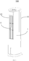
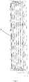
FIG. 1 is a schematic perspective view of a cooling fan according to an embodiment of the present disclosure; -
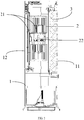
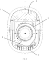
FIG. 2 is a schematic cross-sectional view ofFIG. 1 ; -
FIG. 3 is a schematic cross-sectional view ofFIG. 1 ; -
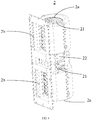
FIG. 4 is a schematic perspective view of a dual centrifugal fan assembly inFIG. 1 ; -
FIG. 5 is a schematic cross-sectional view of an air guiding grille and a flap inFIG. 1 ; -
FIG. 6 is a schematic perspective view of the air guiding grille and the flap inFIG. 1 ; -
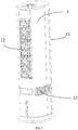
FIG. 7 is a schematic perspective view of the cooling fan according to another embodiment of the present disclosure; -
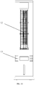
FIG. 8 is a schematic rear view ofFIG. 7 ; -
FIG. 9 is a schematic side view ofFIG. 7 ; and -
FIG. 10 is a schematic front view ofFIG. 7 . -
Label Name Label Name 100 Cooling fan 2b Air outlet end 1 Casing 21 Centrifugal turbine 11 Air inlet 22 Dual- axis motor 12 Air outlet 3 Wet curtain 13 Auxiliary air inlet 4 Air guiding grille 2 Centrifugal fan assembly 5 Flap 2a Air inlet end - The realization of the objective, functional characteristics, advantages of the present disclosure are further described with reference to the accompanying drawings.
- The technical solutions of the embodiments of the present disclosure will be clearly and completely described in the following with reference to the accompanying drawings. It is obvious that the embodiments to be described are only a part rather than all of the embodiments of the present disclosure. All other embodiments obtained by persons skilled in the art based on the embodiments of the present disclosure without creative efforts shall fall within the protection scope of the present disclosure.
- It is to be understood that, all of the directional instructions in the embodiments of the present disclosure (such as up, down, left, right, front, rear...) can only be used for explaining relative position relations, moving condition of the elements under a special form (referring to figures), and so on, if the special form changes, the directional instructions changes accordingly.
- In addition, the descriptions, such as the "first", the "second" in the embodiment of present disclosure, can only be used for describing the aim of description, and cannot be understood as indicating or suggesting relative importance or impliedly indicating the number of the indicated technical feature. Therefore, the feature indicated by the "first", the "second" can express or impliedly include at least one feature. In addition, the meaning of "and/or" appearing throughout the text includes three paratactic schemes, taking "A and/or B" as examples, including scheme A, or scheme B, or schemes that A and B meet at the same time. Besides, the technical solution of each embodiment can be combined with each other, however the technical solution must base on that the ordinary skill in that art can realize the technical solution, when the combination of the technical solutions is contradictory or cannot be realized, it should consider that the combination of the technical solutions does not exist, and is beyond the protection scope of the present disclosure.
- Many cooling fans, especially tower cooling fans, use cross-flow turbines to blow air. However, due to the weak ability of the cross-flow air duct to overcome air resistance, the air speed of the existing tower cooling fan is low, and the blowing distance is not far enough. In addition, in order to reduce the air resistance, the wet curtain of the existing tower cooling fan is thin, usually less than 30mm, resulting in poor cooling effect.
- Referring to
FIG. 1 to FIG. 4 , acooling fan 100 includes acasing 1, acentrifugal fan assembly 2, and awet curtain 3. Thecooling fan 100 further includes a humidifying device for humidifying thewet curtain 3, and the humidifying device supplements thewet curtain 3 with moisture, and the humidifying device may be a water pump and a water pipe assembly. Thecasing 1 includes anair inlet 11 and anair outlet 12. Thecentrifugal fan assembly 2 is provided in thecasing 1. Anair inlet end 2a of thecentrifugal fan assembly 2 is in communication with theair inlet 11. An air outlet end 2b of thecentrifugal fan assembly 2 is in communication with theair outlet 12. Thewet curtain 3 is provided between theair inlet 11 and thecentrifugal fan assembly 2. A thickness of thewet curtain 3 is D, and D is greater than or equal to 35 mm. - In technical solutions of the present disclosure, a
centrifugal fan assembly 2 is provided to replace the existing cross-flow fan. Compared with the cross-flow fan, thecentrifugal fan assembly 2 has a higher air speed and a longer blowing distance. Thus, the centrifugal fan has a lower requirement on air resistance than the cross-flow fan. Therefore, in the present disclosure, thewet curtain 3 can be made thicker. Specifically, the thickness of thewet curtain 3 is D, and D is greater than or equal to 35mm (in the related art, D is generally within 30mm), such that the cooling effect can be improved. - The shape of the
casing 1 is not limited. In order to obtain a better appearance or to facilitate the placement of the coolingfan 100, the cross-section of thecasing 1 is one of oval, circular, and racetrack shape. Specifically, in this embodiment, the cross-section of thecasing 1 is oval. - The cooling effect increases as the thickness D of the
wet curtain 3 increases. But when D increases to a certain value, the cooling effect is not significantly enhanced. For this reason, optionally, D is less than or equal to 80mm. Since when D exceeds 80mm, the cooling effect is not significantly enhanced, but the generated air resistance is significantly increased. - Obviously, when the thickness D is in different values, the cooling effect is different Further, in order to obtain a better cooling effect, the lower limit value of D can be set to one of 40mm and 55mm. Similarly, in order to integrate the air resistance and cooling effect, the upper limit value of D is set to one of 70mm and 65mm, and optionally, D is equal to 60mm, the cooling effect is good at this time. And after D is greater than 60mm, with the increase of thickness, the increasing trend of cooling effect is obviously weakened. Specially, D is greater than or equal to 40mm; and/or D is less than or equal to 70mm; and/or D is greater than or equal to 55mm; and/or D is less than or equal to 65mm; and/or D is equal to 60mm.
- In order to make the cooling
fan 100 have a wide range of air output in the up-down direction, that is, to achieve a large vertical air output structure. In this embodiment, thecentrifugal fan assembly 2 is disposed in the vertical direction, and accordingly, theair outlet 12 is disposed in the vertical direction. Besides, in this embodiment, in order to further increase the air output range of the coolingfan 100 in the vertical direction, thecentrifugal fan assembly 2 includes a dual centrifugal fan assembly, which has twocentrifugal turbines 21 stacked up and down. Obviously, this design is not limited to this. In fact, according to the size of thecentrifugal turbine 21 and the requirements of the air output range of the coolingfan 100 in the vertical direction, three centrifugal fans and more can be provided. - For this reason, it should be noted that the above-mentioned installation direction of the centrifugal fan assembly 2 (that is, up-down direction) and the embodiment in which the
centrifugal fan assembly 2 includes a double centrifugal fan assembly do not need to exist simultaneously, but may alternatively exist. Obviously, in this embodiment, the two implementation manners exist simultaneously. Further, in this embodiment, the dual centrifugal fan assembly further includes adual shaft motor 22. The two shafts of the two-axis motor 22 are connected to the corresponding rotation shafts of the twocentrifugal turbines 21 to drive the twocentrifugal turbines 21 simultaneously. The twocentrifugal turbines 21 are driven to rotate synchronously through a dual-axis motor 22, so that the twocentrifugal turbines 21 can be prevented from rotating asynchronously because they are driven by independent motors. The air flow generated by the two will affect each other, that is, the driving stability by a two-axis motor 22 is good, the air flow interference between thecentrifugal turbines 21 is small, and the blowing distance is long. - In order to make the cooling
fan 100 have a better air output effect, please further refer toFIG. 5 andFIG. 6 . In this embodiment, the coolingfan 100 further includes anair guiding grille 4 and aflap 5, and theair guiding grille 4 is disposed at theair outlet end 2b of thecentrifugal fan assembly 2. The air blown out by theair outlet end 2b of thecentrifugal fan assembly 2 passes through the diversion effect of theair guiding grille 4 and becomes a positive blowout, so that the air is more uniform and the noise is reduced. Theflap 5 is arranged on the outer side of theair guiding grille 4. On the one hand, the function of theflap 5 can increase the air output range by swinging. On the other hand, the function of diversion and boosting can make the distance of the air blown from theair outlet 12 further. - Obviously, from the foregoing description, in this embodiment, the
centrifugal fan assembly 2 is disposed in the up-down direction, and accordingly, theair outlet 12 extends in the up-down direction. Therefore, theflap 5 extends in the up-down direction, and theflap 5 is rotatably mounted on thecasing 1 through the up and down rotation shafts, and is driven to swing laterally (that is, the left-right direction shown in the Figure) through a driving mechanism. The specific driving mechanism is not limited, and the rotation axis of eachflap 5 can be connected through a connecting rod, so that linkage can be achieved. The driving mechanism may include a driving motor and a transmission mechanism. The transmission mechanism converts the rotation of the driving motor into a rotation of one of theflaps 5 to drive eachflap 5 to rotate. - In other embodiments of the present disclosure, referring to
FIG. 7 to FIG. 10 , in order to increase the air input and the heat exchange effect on the air inlet, anauxiliary air inlet 13 is provided on thecasing 1 and below theair inlet 11. Theauxiliary air inlet 13 is in communication with theair inlet 11 of thecentrifugal fan assembly 2. The coolingfan 100 further includes an auxiliary wet curtain (not shown), which is disposed between theauxiliary air inlet 13 and thecentrifugal fan assembly 2. - More specially, the
air outlet 12 is provided on a front of thecasing 1, and theair inlet 11 is provided on a back of thecasing 1. Theauxiliary air inlet 13 is lower than theair outlet 12, and theauxiliary air inlet 13 is in a semi-closed loop shape from the back of thecasing 1 to the front of thecasing 1. A gap of the semi-closed ring is corresponding to theair outlet 12, such that a projection of theair outlet 12 on a horizontal plane is staggered with a projection of theauxiliary air inlet 13 on the horizontal plane. The auxiliary wet curtain is in a semi-circular shape adapted to an area where theauxiliary air inlet 13 is provided. As such, while increasing the area of theauxiliary air inlet 13 and the auxiliary wet curtain, the influence on theair outlet 12 is reduced. - The above are only embodiments of the present disclosure, and thus do not limit the scope of the present disclosure. Under the inventive concept of the present disclosure, any equivalent transformations made by the contents of the specification and drawings of the disclosure, are directly or indirectly applied to related technical fields, and are equally included in the scope of the present disclosure.
Claims (10)
- A cooling fan, comprising:a casing comprising an air inlet and an air outlet;a centrifugal fan assembly provided in the casing, an air inlet end of the centrifugal fan assembly being in communication with the air inlet, and an air outlet end of the centrifugal fan assembly being in communication with the air outlet; anda wet curtain provided between the air inlet and the centrifugal fan assembly;wherein a thickness of the wet curtain is D, and D is greater than or equal to 35mm.
- The cooling fan of claim 1, wherein D is less than or equal to 80mm.
- The cooling fan of claim 1, wherein:D is greater than or equal to 40mm; and/orD is less than or equal to 70mm; and/orD is greater than or equal to 55mm; and/orD is less than or equal to 65mm; and/orD is equal to 60mm.
- The cooling fan of claim 1, wherein:the centrifugal fan assembly comprises a dual centrifugal fan assembly, the dual centrifugal fan assembly comprises two centrifugal turbines stacked up and down; and/orthe centrifugal fan assembly is arranged in an up-down direction, and the air outlet is extended in the up-down direction correspondingly.
- The cooling fan of claim 4, wherein:
the dual centrifugal fan assembly further comprises a dual-axis motor, and two shafts of the dual-axis motor are connected to corresponding rotation shafts of the two centrifugal turbines to drive the two centrifugal turbines simultaneously. - The cooling fan of claim 1, further comprising:an air guiding grille provided at the air outlet end of the centrifugal fan assembly; anda flap provided outside the air guiding grille.
- The cooling fan of claim 6, wherein:the centrifugal fan assembly is arranged in an up-down direction, and the air outlet is extended in the up-down direction correspondingly; andthe flap is extended upwards and downwards, and is rotatably mounted on the casing through up and down rotation shafts, and is driven to swing laterally through a driving mechanism.
- The cooling fan of claim 1, further comprising:
an auxiliary wet curtain, wherein:an auxiliary air inlet is provided on the casing and below the air inlet, and is in communication with the air inlet of the centrifugal fan assembly; andthe auxiliary wet curtain is provided between the auxiliary air inlet and the centrifugal fan assembly. - The cooling fan of claim 8, wherein:the air outlet is provided on a front of the casing, and the air inlet is provided on a back of the casing;the auxiliary air inlet is lower than the air outlet, and the auxiliary air inlet is in a semi-closed loop shape arranged from the back of the casing to the front of the casing;a gap of the semi-closed ring is corresponding to the air outlet, such that a projection of the air outlet on a horizontal plane is staggered with a projection of the auxiliary air inlet on the horizontal plane; andthe auxiliary wet curtain is in a semi-circular shape adapted to an area where the auxiliary air inlet is arranged.
- The cooling fan of claim 1, wherein a cross section of the casing is one of an oval shape, a circular shape, and a racetrack shape.
Applications Claiming Priority (1)
| Application Number | Priority Date | Filing Date | Title |
|---|---|---|---|
| CN201910699167.4A CN112303758A (en) | 2019-07-29 | 2019-07-29 | Cooling fan |
Publications (2)
| Publication Number | Publication Date |
|---|---|
| EP3771831A1 true EP3771831A1 (en) | 2021-02-03 |
| EP3771831B1 EP3771831B1 (en) | 2023-05-24 |
Family
ID=69726411
Family Applications (1)
| Application Number | Title | Priority Date | Filing Date |
|---|---|---|---|
| EP20156580.1A Active EP3771831B1 (en) | 2019-07-29 | 2020-02-11 | Cooling fan |
Country Status (2)
| Country | Link |
|---|---|
| EP (1) | EP3771831B1 (en) |
| CN (1) | CN112303758A (en) |
Cited By (4)
| Publication number | Priority date | Publication date | Assignee | Title |
|---|---|---|---|---|
| CN113405182A (en) * | 2021-07-15 | 2021-09-17 | 珠海格力电器股份有限公司 | Aircraft nose and thermantidote |
| CN115264702A (en) * | 2022-09-15 | 2022-11-01 | 中山市大毅电器科技有限公司 | Fog-free humidifier |
| CN115854421A (en) * | 2022-12-01 | 2023-03-28 | 珠海格力电器股份有限公司 | Indoor unit and air conditioning unit |
| CN116771721A (en) * | 2023-07-10 | 2023-09-19 | 广东英为拓科技有限公司 | Multi-air outlet and adjustable bladeless fan |
Families Citing this family (1)
| Publication number | Priority date | Publication date | Assignee | Title |
|---|---|---|---|---|
| CN114576750B (en) * | 2022-03-22 | 2023-02-03 | 珠海格力电器股份有限公司 | Control method and device for tower type cooling fan and tower type cooling fan |
Citations (3)
| Publication number | Priority date | Publication date | Assignee | Title |
|---|---|---|---|---|
| CN202702694U (en) * | 2012-04-16 | 2013-01-30 | 深圳门德科技有限公司 | Modified wet curtain paper and air purification component and air conditioning |
| CN106765565A (en) * | 2016-12-06 | 2017-05-31 | 美的集团股份有限公司 | The air-out control method of cabinet air-conditioner, air-conditioner and cabinet air-conditioner |
| CN108548258A (en) * | 2018-05-16 | 2018-09-18 | 广东美的环境电器制造有限公司 | cooling fan |
Family Cites Families (7)
| Publication number | Priority date | Publication date | Assignee | Title |
|---|---|---|---|---|
| CN2449116Y (en) * | 2000-06-28 | 2001-09-19 | 广东科龙电器股份有限公司 | Split ground air conditioner with multiple air inlets |
| CN202250963U (en) * | 2011-09-19 | 2012-05-30 | 美的集团有限公司 | Water-cooled evaporative tower fan |
| CN102563760A (en) * | 2012-02-15 | 2012-07-11 | 中国扬子集团滁州扬子空调器有限公司 | Household packaged air conditioner with bottom and rear side mixed air inlet structure |
| CN205064320U (en) * | 2015-09-28 | 2016-03-02 | 广东顺德锐铂汇电子科技有限公司 | Multi -functional thermantidote of trilateral air inlet |
| CN206755527U (en) * | 2017-03-02 | 2017-12-15 | 广东美的环境电器制造有限公司 | An air outlet device and a cooling fan provided with the air outlet device |
| KR20180120877A (en) * | 2017-04-28 | 2018-11-07 | (주)비케이더블유 | Cooling Fan Apparatus |
| CN206755461U (en) * | 2017-06-02 | 2017-12-15 | 宁波正诺电器有限公司 | A kind of thermantidote |
-
2019
- 2019-07-29 CN CN201910699167.4A patent/CN112303758A/en active Pending
-
2020
- 2020-02-11 EP EP20156580.1A patent/EP3771831B1/en active Active
Patent Citations (3)
| Publication number | Priority date | Publication date | Assignee | Title |
|---|---|---|---|---|
| CN202702694U (en) * | 2012-04-16 | 2013-01-30 | 深圳门德科技有限公司 | Modified wet curtain paper and air purification component and air conditioning |
| CN106765565A (en) * | 2016-12-06 | 2017-05-31 | 美的集团股份有限公司 | The air-out control method of cabinet air-conditioner, air-conditioner and cabinet air-conditioner |
| CN108548258A (en) * | 2018-05-16 | 2018-09-18 | 广东美的环境电器制造有限公司 | cooling fan |
Cited By (4)
| Publication number | Priority date | Publication date | Assignee | Title |
|---|---|---|---|---|
| CN113405182A (en) * | 2021-07-15 | 2021-09-17 | 珠海格力电器股份有限公司 | Aircraft nose and thermantidote |
| CN115264702A (en) * | 2022-09-15 | 2022-11-01 | 中山市大毅电器科技有限公司 | Fog-free humidifier |
| CN115854421A (en) * | 2022-12-01 | 2023-03-28 | 珠海格力电器股份有限公司 | Indoor unit and air conditioning unit |
| CN116771721A (en) * | 2023-07-10 | 2023-09-19 | 广东英为拓科技有限公司 | Multi-air outlet and adjustable bladeless fan |
Also Published As
| Publication number | Publication date |
|---|---|
| CN112303758A (en) | 2021-02-02 |
| EP3771831B1 (en) | 2023-05-24 |
Similar Documents
| Publication | Publication Date | Title |
|---|---|---|
| EP3771831B1 (en) | Cooling fan | |
| CN101925783A (en) | Air conditioner | |
| CN106287987B (en) | Air outlet control method of air conditioner cabinet, air conditioner and air conditioner cabinet | |
| CN105526691B (en) | Air guide components and axial flow cabinets | |
| CN101813096A (en) | Double suction sirocco fan with multi-directional wind blowing | |
| EP2584201A1 (en) | Sirocco fan and air-conditioner having the same | |
| CN103363587A (en) | Indoor unit of air conditioner and independent air supply component for air conditioner thereof | |
| CN112728638A (en) | Air guide structure of air outlet of air conditioner, air conditioner | |
| CN107036184A (en) | Outdoor unit of air conditioner | |
| CN208536142U (en) | Cabinet air conditioner indoor unit | |
| CN207081083U (en) | Indoor apparatus of air conditioner | |
| CN204003615U (en) | A kind of spiral case of centrifugal blower | |
| CN108469073B (en) | Window type air conditioning equipment | |
| CN208108308U (en) | Air conditioner indoor unit and air conditioner | |
| US11306729B2 (en) | Axial flow impeller and air conditioner | |
| CN209558507U (en) | Outlet air frame part and air conditioner indoor unit with it | |
| CN104896592A (en) | Vertical-type air conditioner indoor machine | |
| CN205536136U (en) | Floor air conditioner indoor unit | |
| CN219672926U (en) | Air duct structure and fan | |
| CN205578320U (en) | Double wind wheel centrifugal fan and use air cooler and air purifier of this fan | |
| CN108488936A (en) | Window air conditioner | |
| CN107939710A (en) | Fan system, fan and air conditioner fan | |
| CN209558640U (en) | Air conditioner indoor unit air outlet grate and air conditioner indoor unit | |
| CN216769577U (en) | Air conditioner | |
| CN209181123U (en) | Package AC plant |
Legal Events
| Date | Code | Title | Description |
|---|---|---|---|
| PUAI | Public reference made under article 153(3) epc to a published international application that has entered the european phase |
Free format text: ORIGINAL CODE: 0009012 |
|
| STAA | Information on the status of an ep patent application or granted ep patent |
Free format text: STATUS: THE APPLICATION HAS BEEN PUBLISHED |
|
| AK | Designated contracting states |
Kind code of ref document: A1 Designated state(s): AL AT BE BG CH CY CZ DE DK EE ES FI FR GB GR HR HU IE IS IT LI LT LU LV MC MK MT NL NO PL PT RO RS SE SI SK SM TR |
|
| AX | Request for extension of the european patent |
Extension state: BA ME |
|
| STAA | Information on the status of an ep patent application or granted ep patent |
Free format text: STATUS: REQUEST FOR EXAMINATION WAS MADE |
|
| 17P | Request for examination filed |
Effective date: 20210726 |
|
| RBV | Designated contracting states (corrected) |
Designated state(s): AL AT BE BG CH CY CZ DE DK EE ES FI FR GB GR HR HU IE IS IT LI LT LU LV MC MK MT NL NO PL PT RO RS SE SI SK SM TR |
|
| GRAP | Despatch of communication of intention to grant a patent |
Free format text: ORIGINAL CODE: EPIDOSNIGR1 |
|
| STAA | Information on the status of an ep patent application or granted ep patent |
Free format text: STATUS: GRANT OF PATENT IS INTENDED |
|
| INTG | Intention to grant announced |
Effective date: 20230103 |
|
| GRAS | Grant fee paid |
Free format text: ORIGINAL CODE: EPIDOSNIGR3 |
|
| GRAA | (expected) grant |
Free format text: ORIGINAL CODE: 0009210 |
|
| STAA | Information on the status of an ep patent application or granted ep patent |
Free format text: STATUS: THE PATENT HAS BEEN GRANTED |
|
| AK | Designated contracting states |
Kind code of ref document: B1 Designated state(s): AL AT BE BG CH CY CZ DE DK EE ES FI FR GB GR HR HU IE IS IT LI LT LU LV MC MK MT NL NO PL PT RO RS SE SI SK SM TR |
|
| REG | Reference to a national code |
Ref country code: GB Ref legal event code: FG4D |
|
| REG | Reference to a national code |
Ref country code: CH Ref legal event code: EP |
|
| REG | Reference to a national code |
Ref country code: DE Ref legal event code: R096 Ref document number: 602020010993 Country of ref document: DE |
|
| REG | Reference to a national code |
Ref country code: AT Ref legal event code: REF Ref document number: 1569635 Country of ref document: AT Kind code of ref document: T Effective date: 20230615 |
|
| REG | Reference to a national code |
Ref country code: IE Ref legal event code: FG4D |
|
| REG | Reference to a national code |
Ref country code: LT Ref legal event code: MG9D |
|
| REG | Reference to a national code |
Ref country code: NL Ref legal event code: MP Effective date: 20230524 |
|
| REG | Reference to a national code |
Ref country code: AT Ref legal event code: MK05 Ref document number: 1569635 Country of ref document: AT Kind code of ref document: T Effective date: 20230524 |
|
| PG25 | Lapsed in a contracting state [announced via postgrant information from national office to epo] |
Ref country code: SE Free format text: LAPSE BECAUSE OF FAILURE TO SUBMIT A TRANSLATION OF THE DESCRIPTION OR TO PAY THE FEE WITHIN THE PRESCRIBED TIME-LIMIT Effective date: 20230524 Ref country code: PT Free format text: LAPSE BECAUSE OF FAILURE TO SUBMIT A TRANSLATION OF THE DESCRIPTION OR TO PAY THE FEE WITHIN THE PRESCRIBED TIME-LIMIT Effective date: 20230925 Ref country code: NO Free format text: LAPSE BECAUSE OF FAILURE TO SUBMIT A TRANSLATION OF THE DESCRIPTION OR TO PAY THE FEE WITHIN THE PRESCRIBED TIME-LIMIT Effective date: 20230824 Ref country code: NL Free format text: LAPSE BECAUSE OF FAILURE TO SUBMIT A TRANSLATION OF THE DESCRIPTION OR TO PAY THE FEE WITHIN THE PRESCRIBED TIME-LIMIT Effective date: 20230524 Ref country code: ES Free format text: LAPSE BECAUSE OF FAILURE TO SUBMIT A TRANSLATION OF THE DESCRIPTION OR TO PAY THE FEE WITHIN THE PRESCRIBED TIME-LIMIT Effective date: 20230524 Ref country code: AT Free format text: LAPSE BECAUSE OF FAILURE TO SUBMIT A TRANSLATION OF THE DESCRIPTION OR TO PAY THE FEE WITHIN THE PRESCRIBED TIME-LIMIT Effective date: 20230524 |
|
| PG25 | Lapsed in a contracting state [announced via postgrant information from national office to epo] |
Ref country code: RS Free format text: LAPSE BECAUSE OF FAILURE TO SUBMIT A TRANSLATION OF THE DESCRIPTION OR TO PAY THE FEE WITHIN THE PRESCRIBED TIME-LIMIT Effective date: 20230524 Ref country code: PL Free format text: LAPSE BECAUSE OF FAILURE TO SUBMIT A TRANSLATION OF THE DESCRIPTION OR TO PAY THE FEE WITHIN THE PRESCRIBED TIME-LIMIT Effective date: 20230524 Ref country code: LV Free format text: LAPSE BECAUSE OF FAILURE TO SUBMIT A TRANSLATION OF THE DESCRIPTION OR TO PAY THE FEE WITHIN THE PRESCRIBED TIME-LIMIT Effective date: 20230524 Ref country code: LT Free format text: LAPSE BECAUSE OF FAILURE TO SUBMIT A TRANSLATION OF THE DESCRIPTION OR TO PAY THE FEE WITHIN THE PRESCRIBED TIME-LIMIT Effective date: 20230524 Ref country code: IS Free format text: LAPSE BECAUSE OF FAILURE TO SUBMIT A TRANSLATION OF THE DESCRIPTION OR TO PAY THE FEE WITHIN THE PRESCRIBED TIME-LIMIT Effective date: 20230924 Ref country code: HR Free format text: LAPSE BECAUSE OF FAILURE TO SUBMIT A TRANSLATION OF THE DESCRIPTION OR TO PAY THE FEE WITHIN THE PRESCRIBED TIME-LIMIT Effective date: 20230524 Ref country code: GR Free format text: LAPSE BECAUSE OF FAILURE TO SUBMIT A TRANSLATION OF THE DESCRIPTION OR TO PAY THE FEE WITHIN THE PRESCRIBED TIME-LIMIT Effective date: 20230825 |
|
| PG25 | Lapsed in a contracting state [announced via postgrant information from national office to epo] |
Ref country code: FI Free format text: LAPSE BECAUSE OF FAILURE TO SUBMIT A TRANSLATION OF THE DESCRIPTION OR TO PAY THE FEE WITHIN THE PRESCRIBED TIME-LIMIT Effective date: 20230524 |
|
| PG25 | Lapsed in a contracting state [announced via postgrant information from national office to epo] |
Ref country code: SK Free format text: LAPSE BECAUSE OF FAILURE TO SUBMIT A TRANSLATION OF THE DESCRIPTION OR TO PAY THE FEE WITHIN THE PRESCRIBED TIME-LIMIT Effective date: 20230524 |
|
| PG25 | Lapsed in a contracting state [announced via postgrant information from national office to epo] |
Ref country code: SM Free format text: LAPSE BECAUSE OF FAILURE TO SUBMIT A TRANSLATION OF THE DESCRIPTION OR TO PAY THE FEE WITHIN THE PRESCRIBED TIME-LIMIT Effective date: 20230524 Ref country code: SK Free format text: LAPSE BECAUSE OF FAILURE TO SUBMIT A TRANSLATION OF THE DESCRIPTION OR TO PAY THE FEE WITHIN THE PRESCRIBED TIME-LIMIT Effective date: 20230524 Ref country code: RO Free format text: LAPSE BECAUSE OF FAILURE TO SUBMIT A TRANSLATION OF THE DESCRIPTION OR TO PAY THE FEE WITHIN THE PRESCRIBED TIME-LIMIT Effective date: 20230524 Ref country code: EE Free format text: LAPSE BECAUSE OF FAILURE TO SUBMIT A TRANSLATION OF THE DESCRIPTION OR TO PAY THE FEE WITHIN THE PRESCRIBED TIME-LIMIT Effective date: 20230524 Ref country code: DK Free format text: LAPSE BECAUSE OF FAILURE TO SUBMIT A TRANSLATION OF THE DESCRIPTION OR TO PAY THE FEE WITHIN THE PRESCRIBED TIME-LIMIT Effective date: 20230524 Ref country code: CZ Free format text: LAPSE BECAUSE OF FAILURE TO SUBMIT A TRANSLATION OF THE DESCRIPTION OR TO PAY THE FEE WITHIN THE PRESCRIBED TIME-LIMIT Effective date: 20230524 |
|
| REG | Reference to a national code |
Ref country code: DE Ref legal event code: R097 Ref document number: 602020010993 Country of ref document: DE |
|
| PLBE | No opposition filed within time limit |
Free format text: ORIGINAL CODE: 0009261 |
|
| STAA | Information on the status of an ep patent application or granted ep patent |
Free format text: STATUS: NO OPPOSITION FILED WITHIN TIME LIMIT |
|
| 26N | No opposition filed |
Effective date: 20240227 |
|
| PG25 | Lapsed in a contracting state [announced via postgrant information from national office to epo] |
Ref country code: SI Free format text: LAPSE BECAUSE OF FAILURE TO SUBMIT A TRANSLATION OF THE DESCRIPTION OR TO PAY THE FEE WITHIN THE PRESCRIBED TIME-LIMIT Effective date: 20230524 |
|
| PG25 | Lapsed in a contracting state [announced via postgrant information from national office to epo] |
Ref country code: SI Free format text: LAPSE BECAUSE OF FAILURE TO SUBMIT A TRANSLATION OF THE DESCRIPTION OR TO PAY THE FEE WITHIN THE PRESCRIBED TIME-LIMIT Effective date: 20230524 Ref country code: IT Free format text: LAPSE BECAUSE OF FAILURE TO SUBMIT A TRANSLATION OF THE DESCRIPTION OR TO PAY THE FEE WITHIN THE PRESCRIBED TIME-LIMIT Effective date: 20230524 |
|
| PG25 | Lapsed in a contracting state [announced via postgrant information from national office to epo] |
Ref country code: MC Free format text: LAPSE BECAUSE OF FAILURE TO SUBMIT A TRANSLATION OF THE DESCRIPTION OR TO PAY THE FEE WITHIN THE PRESCRIBED TIME-LIMIT Effective date: 20230524 |
|
| REG | Reference to a national code |
Ref country code: CH Ref legal event code: PL |
|
| PG25 | Lapsed in a contracting state [announced via postgrant information from national office to epo] |
Ref country code: LU Free format text: LAPSE BECAUSE OF NON-PAYMENT OF DUE FEES Effective date: 20240211 |
|
| PG25 | Lapsed in a contracting state [announced via postgrant information from national office to epo] |
Ref country code: CH Free format text: LAPSE BECAUSE OF NON-PAYMENT OF DUE FEES Effective date: 20240229 |
|
| PG25 | Lapsed in a contracting state [announced via postgrant information from national office to epo] |
Ref country code: LU Free format text: LAPSE BECAUSE OF NON-PAYMENT OF DUE FEES Effective date: 20240211 Ref country code: CH Free format text: LAPSE BECAUSE OF NON-PAYMENT OF DUE FEES Effective date: 20240229 |
|
| PG25 | Lapsed in a contracting state [announced via postgrant information from national office to epo] |
Ref country code: BG Free format text: LAPSE BECAUSE OF FAILURE TO SUBMIT A TRANSLATION OF THE DESCRIPTION OR TO PAY THE FEE WITHIN THE PRESCRIBED TIME-LIMIT Effective date: 20230524 |
|
| PG25 | Lapsed in a contracting state [announced via postgrant information from national office to epo] |
Ref country code: BG Free format text: LAPSE BECAUSE OF FAILURE TO SUBMIT A TRANSLATION OF THE DESCRIPTION OR TO PAY THE FEE WITHIN THE PRESCRIBED TIME-LIMIT Effective date: 20230524 |
|
| REG | Reference to a national code |
Ref country code: BE Ref legal event code: MM Effective date: 20240229 |
|
| PG25 | Lapsed in a contracting state [announced via postgrant information from national office to epo] |
Ref country code: BE Free format text: LAPSE BECAUSE OF NON-PAYMENT OF DUE FEES Effective date: 20240229 |
|
| PG25 | Lapsed in a contracting state [announced via postgrant information from national office to epo] |
Ref country code: IE Free format text: LAPSE BECAUSE OF NON-PAYMENT OF DUE FEES Effective date: 20240211 |
|
| PG25 | Lapsed in a contracting state [announced via postgrant information from national office to epo] |
Ref country code: IE Free format text: LAPSE BECAUSE OF NON-PAYMENT OF DUE FEES Effective date: 20240211 Ref country code: BE Free format text: LAPSE BECAUSE OF NON-PAYMENT OF DUE FEES Effective date: 20240229 |
|
| PGFP | Annual fee paid to national office [announced via postgrant information from national office to epo] |
Ref country code: DE Payment date: 20250219 Year of fee payment: 6 |
|
| PGFP | Annual fee paid to national office [announced via postgrant information from national office to epo] |
Ref country code: FR Payment date: 20250220 Year of fee payment: 6 |
|
| PGFP | Annual fee paid to national office [announced via postgrant information from national office to epo] |
Ref country code: GB Payment date: 20250219 Year of fee payment: 6 |
|
| REG | Reference to a national code |
Ref country code: DE Ref legal event code: R082 Ref document number: 602020010993 Country of ref document: DE Representative=s name: MAUCHER JENKINS PATENTANWAELTE & RECHTSANWAELT, DE |
|
| PG25 | Lapsed in a contracting state [announced via postgrant information from national office to epo] |
Ref country code: CY Free format text: LAPSE BECAUSE OF FAILURE TO SUBMIT A TRANSLATION OF THE DESCRIPTION OR TO PAY THE FEE WITHIN THE PRESCRIBED TIME-LIMIT; INVALID AB INITIO Effective date: 20200211 |
|
| PG25 | Lapsed in a contracting state [announced via postgrant information from national office to epo] |
Ref country code: HU Free format text: LAPSE BECAUSE OF FAILURE TO SUBMIT A TRANSLATION OF THE DESCRIPTION OR TO PAY THE FEE WITHIN THE PRESCRIBED TIME-LIMIT; INVALID AB INITIO Effective date: 20200211 |
|
| PG25 | Lapsed in a contracting state [announced via postgrant information from national office to epo] |
Ref country code: TR Free format text: LAPSE BECAUSE OF FAILURE TO SUBMIT A TRANSLATION OF THE DESCRIPTION OR TO PAY THE FEE WITHIN THE PRESCRIBED TIME-LIMIT Effective date: 20230524 |