EP3771806A1 - Exhaust system for an internal combustion engine - Google Patents
Exhaust system for an internal combustion engine Download PDFInfo
- Publication number
- EP3771806A1 EP3771806A1 EP20188401.2A EP20188401A EP3771806A1 EP 3771806 A1 EP3771806 A1 EP 3771806A1 EP 20188401 A EP20188401 A EP 20188401A EP 3771806 A1 EP3771806 A1 EP 3771806A1
- Authority
- EP
- European Patent Office
- Prior art keywords
- silencing
- exhaust system
- exhaust
- valve
- silencing valve
- Prior art date
- Legal status (The legal status is an assumption and is not a legal conclusion. Google has not performed a legal analysis and makes no representation as to the accuracy of the status listed.)
- Granted
Links
Images


Classifications
-
- F—MECHANICAL ENGINEERING; LIGHTING; HEATING; WEAPONS; BLASTING
- F01—MACHINES OR ENGINES IN GENERAL; ENGINE PLANTS IN GENERAL; STEAM ENGINES
- F01N—GAS-FLOW SILENCERS OR EXHAUST APPARATUS FOR MACHINES OR ENGINES IN GENERAL; GAS-FLOW SILENCERS OR EXHAUST APPARATUS FOR INTERNAL-COMBUSTION ENGINES
- F01N13/00—Exhaust or silencing apparatus characterised by constructional features
- F01N13/08—Other arrangements or adaptations of exhaust conduits
-
- F—MECHANICAL ENGINEERING; LIGHTING; HEATING; WEAPONS; BLASTING
- F01—MACHINES OR ENGINES IN GENERAL; ENGINE PLANTS IN GENERAL; STEAM ENGINES
- F01N—GAS-FLOW SILENCERS OR EXHAUST APPARATUS FOR MACHINES OR ENGINES IN GENERAL; GAS-FLOW SILENCERS OR EXHAUST APPARATUS FOR INTERNAL-COMBUSTION ENGINES
- F01N1/00—Silencing apparatus characterised by method of silencing
- F01N1/16—Silencing apparatus characterised by method of silencing by using movable parts
- F01N1/165—Silencing apparatus characterised by method of silencing by using movable parts for adjusting flow area
-
- F—MECHANICAL ENGINEERING; LIGHTING; HEATING; WEAPONS; BLASTING
- F01—MACHINES OR ENGINES IN GENERAL; ENGINE PLANTS IN GENERAL; STEAM ENGINES
- F01N—GAS-FLOW SILENCERS OR EXHAUST APPARATUS FOR MACHINES OR ENGINES IN GENERAL; GAS-FLOW SILENCERS OR EXHAUST APPARATUS FOR INTERNAL-COMBUSTION ENGINES
- F01N1/00—Silencing apparatus characterised by method of silencing
- F01N1/16—Silencing apparatus characterised by method of silencing by using movable parts
- F01N1/166—Silencing apparatus characterised by method of silencing by using movable parts for changing the flow path through the silencer or for adjusting the dimensions of a chamber or a pipe
-
- F—MECHANICAL ENGINEERING; LIGHTING; HEATING; WEAPONS; BLASTING
- F01—MACHINES OR ENGINES IN GENERAL; ENGINE PLANTS IN GENERAL; STEAM ENGINES
- F01N—GAS-FLOW SILENCERS OR EXHAUST APPARATUS FOR MACHINES OR ENGINES IN GENERAL; GAS-FLOW SILENCERS OR EXHAUST APPARATUS FOR INTERNAL-COMBUSTION ENGINES
- F01N1/00—Silencing apparatus characterised by method of silencing
- F01N1/16—Silencing apparatus characterised by method of silencing by using movable parts
- F01N1/168—Silencing apparatus characterised by method of silencing by using movable parts for controlling or modifying silencing characteristics only
-
- F—MECHANICAL ENGINEERING; LIGHTING; HEATING; WEAPONS; BLASTING
- F01—MACHINES OR ENGINES IN GENERAL; ENGINE PLANTS IN GENERAL; STEAM ENGINES
- F01N—GAS-FLOW SILENCERS OR EXHAUST APPARATUS FOR MACHINES OR ENGINES IN GENERAL; GAS-FLOW SILENCERS OR EXHAUST APPARATUS FOR INTERNAL-COMBUSTION ENGINES
- F01N1/00—Silencing apparatus characterised by method of silencing
- F01N1/16—Silencing apparatus characterised by method of silencing by using movable parts
- F01N1/18—Silencing apparatus characterised by method of silencing by using movable parts having rotary movement
-
- F—MECHANICAL ENGINEERING; LIGHTING; HEATING; WEAPONS; BLASTING
- F02—COMBUSTION ENGINES; HOT-GAS OR COMBUSTION-PRODUCT ENGINE PLANTS
- F02D—CONTROLLING COMBUSTION ENGINES
- F02D9/00—Controlling engines by throttling air or fuel-and-air induction conduits or exhaust conduits
- F02D9/04—Controlling engines by throttling air or fuel-and-air induction conduits or exhaust conduits concerning exhaust conduits
- F02D9/06—Exhaust brakes
-
- F—MECHANICAL ENGINEERING; LIGHTING; HEATING; WEAPONS; BLASTING
- F02—COMBUSTION ENGINES; HOT-GAS OR COMBUSTION-PRODUCT ENGINE PLANTS
- F02D—CONTROLLING COMBUSTION ENGINES
- F02D9/00—Controlling engines by throttling air or fuel-and-air induction conduits or exhaust conduits
- F02D9/08—Throttle valves specially adapted therefor; Arrangements of such valves in conduits
- F02D9/10—Throttle valves specially adapted therefor; Arrangements of such valves in conduits having pivotally-mounted flaps
- F02D9/1005—Details of the flap
- F02D9/101—Special flap shapes, ribs, bores or the like
-
- F—MECHANICAL ENGINEERING; LIGHTING; HEATING; WEAPONS; BLASTING
- F01—MACHINES OR ENGINES IN GENERAL; ENGINE PLANTS IN GENERAL; STEAM ENGINES
- F01N—GAS-FLOW SILENCERS OR EXHAUST APPARATUS FOR MACHINES OR ENGINES IN GENERAL; GAS-FLOW SILENCERS OR EXHAUST APPARATUS FOR INTERNAL-COMBUSTION ENGINES
- F01N2240/00—Combination or association of two or more different exhaust treating devices, or of at least one such device with an auxiliary device, not covered by indexing codes F01N2230/00 or F01N2250/00, one of the devices being
- F01N2240/36—Combination or association of two or more different exhaust treating devices, or of at least one such device with an auxiliary device, not covered by indexing codes F01N2230/00 or F01N2250/00, one of the devices being an exhaust flap
-
- F—MECHANICAL ENGINEERING; LIGHTING; HEATING; WEAPONS; BLASTING
- F02—COMBUSTION ENGINES; HOT-GAS OR COMBUSTION-PRODUCT ENGINE PLANTS
- F02D—CONTROLLING COMBUSTION ENGINES
- F02D2200/00—Input parameters for engine control
- F02D2200/02—Input parameters for engine control the parameters being related to the engine
- F02D2200/10—Parameters related to the engine output, e.g. engine torque or engine speed
- F02D2200/101—Engine speed
Definitions
- the invention relates to an exhaust system for an internal combustion engine.
- An internal combustion engine is provided with an exhaust system, which has the function of releasing the gases produced by the combustion into the atmosphere limiting both the noise and the content of polluting substances.
- a modern exhaust system comprises: an exhaust duct, along which the exhaust gases coming from the internal combustion engine flow, a series of pollutant reducing devices (for example one or more monolithic catalysts and a particulate filter) arranged along the exhaust duct, and at least one silencer arranged along the exhaust duct downstream of the pollutant reducing devices.
- a silencer comprises a tubular body, which typically has an elliptical cross section and is provided with an inlet opening and with an outlet opening.
- a labyrinth which determines a path for the exhaust gases from the inlet opening to the outlet opening; said labyrinth normally consists of diaphragms (or partitions), which are arranged crosswise (namely, perpendicularly to the longitudinal axis of the tubular body) so as to define chambers inside the tubular body, and of tubes, which connect the chambers to one another.
- the exhaust back pressure generated by the silencer i.e.
- a bypass duct is provided, which is arranged in parallel to the silencer (namely, is designed to bypass the silencer) and is regulated by a bypass valve, which is kept closed at low rpms (so as to maximize the silencing action, sacrificing performances, which, anyway, are nor essential at low rpms) and is opened at high rpms (so as to reduce the exhaust back pressure, sacrificing the silencing, which should not be important when the internal combustion engine operates at high rpms).
- the object of the invention is to provide an exhaust system for an internal combustion engine, said exhaust system allowing for an ideal silencing at low rpms, allowing the exhaust back pressure to be minimized at high rpms, having a small weight as well as small dimensions and, at the same time, being easy and economic to be manufactured.
- number 1 indicates, as a whole, a car provided with two front wheels 2 and with two rear drive wheels 3, which receive the torque from an internal combustion engine 4 supercharged by means of a turbocharger and arranged in a front position.
- the car 1 is provided with a passenger compartment 5 which is designed to house the driver and possible passengers.
- the internal combustion engine 4 is a "V8" engine and has two (twin) banks with four cylinders arranged at an angle relative to one another so as to form a "V".
- the four cylinders are connected to an intake manifold (not shown) by means of two intake valves and to an exhaust manifold (not shown) by means of two exhaust valves; each exhaust manifold collects the gases produced by the combustion, which cyclically flow out of the exhaust valves.
- the internal combustion engine 4 is provided with an exhaust system 6, which has the function of releasing the gases produced by the combustion into the atmosphere limiting both the noise and the content of polluting substances.
- the exhaust system 6 comprises two exhaust ducts 7, each originating from a corresponding exhaust manifold, so to receive the gases produced by the combustion from the exhaust manifold, and ending in the area of the tail of the car 1.
- exhaust gas treatment devices 8 there always is at least one catalytic converter and there could also be a particular filter (in order to comply with the new EURO6C standards on polluting emissions, car manufacturers use a particulate filter - called GPF, which stands for "Gasoline Particulate Filter” - also in gasoline engines).
- GPF particulate filter
- Each exhaust duct 7 is provided with a silencing device 10, which is arranged along the exhaust duct 7 downstream of the exhaust gas treatment devices 8 and generally close to the end of the exhaust duct 7.
- each silencing device 10 comprises a silencing valve 11, which intercepts the corresponding exhaust duct 7 (namely, is inserted inside the corresponding exhaust duct 7 so as to locally change the exhaust gas passage section).
- Each silencing valve 11 is movable between a completely open position (shown in figure 2 and 4 ) and a completely closed position (shown in figure 3 ).
- each silencing valve 11 In the completely closed position (shown in figure 3 ), each silencing valve 11 has a first (minimum) free section for the passage of the exhaust gases having an area A1 other than zero, so that the exhaust gases can flow through the silencing valve 11 even when the silencing valve 11 is in the completely closed position.
- each silencing valve 11 In the completely open position (shown in figures 2 and 4 ), each silencing valve 11 has a second free section for the passage of the exhaust gases having a (maximum) area A2.
- the area A1 of the first free section ranges from 8% to 24% of the area A2 of the second free section (corresponding to the completely open position).
- the area A1 of the first free section (corresponding to the completely closed position) normally is at least equal to 220 mm 2 and generally ranges from 300 mm 2 to 750 mm 2 .
- the first free section consists of two slits 12, which are separate from one another and are arranged at opposite ends of a shutter 13 of the silencing valve 11.
- Each slit 12 of the first free section preferably has the shape of a crescent of moon.
- the shape of a crescent of moon of the slits 12 making up the first free section (corresponding to the completely closed position) is particularly advantageous, as it prevents the exhaust gases from producing, by flowing through a silencing valve 11, whistles (or other unusual sounds), which could be extremely negative for they would (at least partly) jeopardize the silencing function of the silencing valve 11.
- the two slits 12 of the first free section are mirror-like and have the same size; in the embodiment shown in figure 3 , the area A1 of the first free section (corresponding to the completely closed position) is equal to approximately 640 mm 2 , whereas, in the embodiment shown in figure 5 , the area A1 of the first free section (corresponding to the completely closed position) is equal to approximately 320 mm 2 .
- the two slits 12 of the first free section (corresponding to the completely closed position) have different sizes; for example, a slit 12 has a total area equal to 2-7 times a total area of the other slit 12.
- each silencing valve 11 comprises a tubular body 14, which is flown through by the exhaust gases (namely, is inserted along the corresponding exhaust duct 7) and has a circular cross section; furthermore, each silencing valve 11 comprises the shutter 13, which is butterfly-shaped (namely, the shutter 13 is a butterfly plate), has an elliptical cross section and is mounted in a rotary manner inside the tubular body 14 so as to rotate around a rotation axis 15 arranged at the centre and oriented crosswise relative to the tubular body 14.
- each silencing valve 11 the shutter 13 rotates around the rotations axis 15 between the completely open position (shown in figure 2 and 4 ) and the completely closed position (shown in figure 3 , 5 and 6 ).
- Each shutter 13 has, at the centre, a cylindrical bulge, which constitutes a shaft 16, by means of which the shutter 13 is hinged at the two opposite ends so as to rotate around the rotation axis 15.
- each shutter 13 has an elliptical shape having a larger size (along the main axis and oriented perpendicularly to the rotation axis 15) and a smaller size (along the minor axis and oriented parallel to the rotation axis 15) : the larger size of each butterfly shutter 13 is equal to an inner diameter of the tubular body 14 and the smaller size of each butterfly shutter 13 is smaller than the inner diameter of the tubular body 14; in this way, in the completely closed position (shown in figures 3 , 5 and 6 ), each silencing valve 11 has the first (minimum) free section for the passage of the exhaust gases having an area A1 other than zero, so that the exhaust gases can flow through the silencing valve 11 even when the silencing valve 11 is in the completely closed position.
- each silencing valve 11 comprises an electric actuator 17, which is capable of placing and holding the silencing valve 11 in all the intermediate positions comprised between the completely open position (shown in figures 2 and 4 ) and the completely closed position (shown in figures 3 , 5 and 6 ). Furthermore, a control unit 18 is provided, which is configured to change the position of each silencing valve 11 depending on a number of revolutions per minute and on a load of the internal combustion engine 4.
- control unit 18 is configured to change the position of each silencing valve 11 also depending on a gear engaged in a gearbox coupled to the internal combustion engine 4 and to change the position of each silencing valve 11 also depending on the driving mode selected by the driver (namely, it can be a sports driving mode, a racing driving mode, a city driving mode, a motorway driving mode, a wet-road driving mode...., which is generally selected by the driver by acting upon a selector called "hand lever ”) .
- control unit 18 there are stored different maps (each corresponding to one or more driving modes), which provide, as an output, the desired (ideal) position of each silencing valve 11 based on the data provided as an input on the number of revolutions per minute and on the engine load of the internal combustion engine 4 as well as on the gear engaged in the gearbox coupled to the internal combustion engine 4.
- each map stored in the control unit 18 comprises a limited number of points and, therefore, the control unit 18 could carry out interpolations between the closest points of a map in order to determine the desired (ideal) position of each silencing valve 11.
- the control unit 18 is configured to move each silencing valve 11 towards the completely closed position (namely, to close the silencing valve 11) in the presence of a small number of revolutions per minute and of small loads of the internal combustion engine 4 and to move the silencing valve 11 towards the completely open position (namely, to open the silencing valve 11) in the presence of a large number of revolutions per minute and of great loads of the internal combustion engine 4. Furthermore, the control unit 18 is configured to move each silencing valve 11 towards the completely closed position (namely, to close the silencing valve 11) when the low gears are engaged and to move the silencing valve 11 towards the completely open position (namely, to open the silencing valve 11) when the high gears are engaged.
- each exhaust duct 7 remains single also downstream of the silencing valve 11.
- each exhaust duct 7 divides itself, namely has a bifurcation 19, downstream of which the exhaust duct 7 is double (and, hence, ends with two corresponding decorative tail pipes 9).
- each silencing device 10 only and exclusively comprises the silencing valve 11, namely each silencing device 10 has no silencer arranged upstream or downstream of the silencing valve 11. Indeed, the functions of a traditional silencer and of the respective bypass duct are performed by the silencing valves 11.
- each silencing valve 11 In the completely open position (shown in figures 2 and 4 ), each silencing valve 11 has the minimum exhaust back pressure (namely, allows performances to be maximized) and also has the minimum silencing ability (basically zero); on the other hand, in the completely closed position (shown in figures 3 , 5 and 6 ), each silencing valve 11 has the maximum exhaust back pressure (namely, jeopardizes performances to a greater extent) and also has the maximum silencing ability (basically equivalent to the silencing ability of a traditional silencer).
- the control valve 18 is configured to close each silencing valve 11 (namely, to move each silencing valve 11 towards the completely closed position) when it is necessary (useful) to favour silencing rather than performances and to open each silencing valve 11 (namely, to move each silencing valve 11 towards the completely open position) when it is necessary (useful) to favour performances rather than silencing.
- the internal combustion engine 4 has eight cylinders 6 arranged in V shape.
- the internal combustion engine could have a different number of cylinders and/or a different arrangement of the cylinders; in case of internal combustion engines with inline cylinders (hence, with one single bank of cylinders), there usually is one single exhaust duct 7 and, therefore, one single silencing device 10.
- the internal combustion engine 4 is supercharged; according to other embodiments which are not shown herein, the internal combustion engine 4 is not supercharged, namely is an aspirated engine.
- the exhaust system 6 described above has numerous advantages.
- the exhaust system 6 described above allows for an ideal silencing at low rpms (keeping the silencing valves 11 completely closed) and, at the same time, allows the exhaust back pressure to be minimized at high rpms (keeping the silencing valves 11 completely open).
- the exhaust system 6 described above is particularly light and compact, since it lacks the traditional silencer (which inevitably has a large volume) and the respective bypass duct, whose functions are carried out by the silencing valves 11, which have extremely small sizes.
- the exhaust system 6 described above is easy and economic to be manufactured, since, compared to a similar traditional exhaust system 6, completely avoids the cost of the silencer (which, in a traditional exhaust system 6, is always combined with a bypass duct regulated by corresponding bypass valve having a cost that is similar to the cost of a silencing valve 11).
Landscapes
- Engineering & Computer Science (AREA)
- Chemical & Material Sciences (AREA)
- Combustion & Propulsion (AREA)
- Mechanical Engineering (AREA)
- General Engineering & Computer Science (AREA)
- Exhaust Silencers (AREA)
- Chemical Kinetics & Catalysis (AREA)
- Health & Medical Sciences (AREA)
- Toxicology (AREA)
- Cylinder Crankcases Of Internal Combustion Engines (AREA)
Abstract
Description
- This patent application claims priority from Italian patent application no.
102019000013317 filed on July 30, 2019 - The invention relates to an exhaust system for an internal combustion engine.
- An internal combustion engine is provided with an exhaust system, which has the function of releasing the gases produced by the combustion into the atmosphere limiting both the noise and the content of polluting substances. A modern exhaust system comprises: an exhaust duct, along which the exhaust gases coming from the internal combustion engine flow, a series of pollutant reducing devices (for example one or more monolithic catalysts and a particulate filter) arranged along the exhaust duct, and at least one silencer arranged along the exhaust duct downstream of the pollutant reducing devices.
- Generally speaking, a silencer comprises a tubular body, which typically has an elliptical cross section and is provided with an inlet opening and with an outlet opening. Inside the tubular body there is defined a labyrinth, which determines a path for the exhaust gases from the inlet opening to the outlet opening; said labyrinth normally consists of diaphragms (or partitions), which are arranged crosswise (namely, perpendicularly to the longitudinal axis of the tubular body) so as to define chambers inside the tubular body, and of tubes, which connect the chambers to one another. In a traditional silencer ensuring a high damping of the noise at low rpms, the exhaust back pressure generated by the silencer (i.e. the loss of pressure caused in the exhaust gases when they flow through the silencer) exponentially grows as the number of revolutions per minute of the internal combustion engine increases (i.e. as the mean speed of the exhaust gases increases) . As a consequence, in order to avoid too high exhaust back pressure values at high rpms, a bypass duct is provided, which is arranged in parallel to the silencer (namely, is designed to bypass the silencer) and is regulated by a bypass valve, which is kept closed at low rpms (so as to maximize the silencing action, sacrificing performances, which, anyway, are nor essential at low rpms) and is opened at high rpms (so as to reduce the exhaust back pressure, sacrificing the silencing, which should not be important when the internal combustion engine operates at high rpms).
- Documents
US2018223709A1 ,DE102009051098A1 ,US2015283897A1 ,US2017067380A1 ,US4609068A ,DE202017000834U1 andEP1445451A2 describe an exhaust system for an internal combustion engine, which is provided with a silencing valve, which is movable between a completely open position and a completely closed position; in the completely closed position, the silencing valve has a free section for the passage of the exhaust gases having an area other than zero, so that the exhaust gases can flow through the silencing valve even when the silencing valve is in the completely closed position. - The object of the invention is to provide an exhaust system for an internal combustion engine, said exhaust system allowing for an ideal silencing at low rpms, allowing the exhaust back pressure to be minimized at high rpms, having a small weight as well as small dimensions and, at the same time, being easy and economic to be manufactured.
- According to the invention, there is provided a an exhaust system for an internal combustion engine according to the appended claims.
- The appended claims describe preferred embodiments of the invention and form an integral part of the description.
- The invention will now be described with reference to the accompanying drawings, showing a non-limiting embodiment thereof, wherein:
-
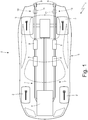
figure 1 is a schematic view of car, which is driven by an internal combustion engine provided with an exhaust system according to the invention; -
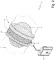
figure 2 is a schematic, perspective view of a silencing valve of the exhaust system offigure 1 in a completely open position; -
figure 3 is a front view of the silencing valve offigure 2 in a completely closed position; -
figure 4 is a front view of the silencing valve offigure 2 in a completely open position; -
figures 5 and6 are two front views of respective variants of the silencing valve offigure 2 in a completely closed position; and -
figure 7 is a schematic view of a variant of an end portion of the exhaust system offigure 1 . - In
figure 1 ,number 1 indicates, as a whole, a car provided with twofront wheels 2 and with tworear drive wheels 3, which receive the torque from aninternal combustion engine 4 supercharged by means of a turbocharger and arranged in a front position. Thecar 1 is provided with apassenger compartment 5 which is designed to house the driver and possible passengers. - The
internal combustion engine 4 is a "V8" engine and has two (twin) banks with four cylinders arranged at an angle relative to one another so as to form a "V". In each bank, the four cylinders are connected to an intake manifold (not shown) by means of two intake valves and to an exhaust manifold (not shown) by means of two exhaust valves; each exhaust manifold collects the gases produced by the combustion, which cyclically flow out of the exhaust valves. - The
internal combustion engine 4 is provided with anexhaust system 6, which has the function of releasing the gases produced by the combustion into the atmosphere limiting both the noise and the content of polluting substances. Theexhaust system 6 comprises twoexhaust ducts 7, each originating from a corresponding exhaust manifold, so to receive the gases produced by the combustion from the exhaust manifold, and ending in the area of the tail of thecar 1. Along eachexhaust duct 7 there are known exhaust gas treatment devices 8: there always is at least one catalytic converter and there could also be a particular filter (in order to comply with the new EURO6C standards on polluting emissions, car manufacturers use a particulate filter - called GPF, which stands for "Gasoline Particulate Filter" - also in gasoline engines). At the end of eachexhaust duct 7 there is adecorative tail pipe 9, which only fulfils decorative functions (namely, masking theexhaust duct 7 with a pleasant shape, which also matches the setting of the car 1). - Each
exhaust duct 7 is provided with asilencing device 10, which is arranged along theexhaust duct 7 downstream of the exhaustgas treatment devices 8 and generally close to the end of theexhaust duct 7. According tofigure 2 , eachsilencing device 10 comprises asilencing valve 11, which intercepts the corresponding exhaust duct 7 (namely, is inserted inside thecorresponding exhaust duct 7 so as to locally change the exhaust gas passage section). - Each
silencing valve 11 is movable between a completely open position (shown infigure 2 and4 ) and a completely closed position (shown infigure 3 ). In the completely closed position (shown infigure 3 ), eachsilencing valve 11 has a first (minimum) free section for the passage of the exhaust gases having an area A1 other than zero, so that the exhaust gases can flow through thesilencing valve 11 even when thesilencing valve 11 is in the completely closed position. In the completely open position (shown infigures 2 and4 ), eachsilencing valve 11 has a second free section for the passage of the exhaust gases having a (maximum) area A2. According to a preferred embodiment, the area A1 of the first free section (corresponding to the completely closed position) ranges from 8% to 24% of the area A2 of the second free section (corresponding to the completely open position). - The area A1 of the first free section (corresponding to the completely closed position) normally is at least equal to 220 mm2 and generally ranges from 300 mm2 to 750 mm2.
- According to
figures 3 ,5 and6 (all showing asilencing valve 11 in the completely closed position), in the completely closed position, the first free section consists of twoslits 12, which are separate from one another and are arranged at opposite ends of ashutter 13 of thesilencing valve 11. - Each
slit 12 of the first free section (corresponding to the completely closed position) preferably has the shape of a crescent of moon. The shape of a crescent of moon of theslits 12 making up the first free section (corresponding to the completely closed position) is particularly advantageous, as it prevents the exhaust gases from producing, by flowing through asilencing valve 11, whistles (or other unusual sounds), which could be extremely negative for they would (at least partly) jeopardize the silencing function of thesilencing valve 11. - In the embodiments shown in
figures 3 and5 , the twoslits 12 of the first free section (corresponding to the completely closed position) are mirror-like and have the same size; in the embodiment shown infigure 3 , the area A1 of the first free section (corresponding to the completely closed position) is equal to approximately 640 mm2, whereas, in the embodiment shown infigure 5 , the area A1 of the first free section (corresponding to the completely closed position) is equal to approximately 320 mm2. In the embodiment shown infigure 6 , the twoslits 12 of the first free section (corresponding to the completely closed position) have different sizes; for example, aslit 12 has a total area equal to 2-7 times a total area of theother slit 12. - According to
figures 2-6 , eachsilencing valve 11 comprises atubular body 14, which is flown through by the exhaust gases (namely, is inserted along the corresponding exhaust duct 7) and has a circular cross section; furthermore, eachsilencing valve 11 comprises theshutter 13, which is butterfly-shaped (namely, theshutter 13 is a butterfly plate), has an elliptical cross section and is mounted in a rotary manner inside thetubular body 14 so as to rotate around arotation axis 15 arranged at the centre and oriented crosswise relative to thetubular body 14. As a consequence, in eachsilencing valve 11, theshutter 13 rotates around therotations axis 15 between the completely open position (shown infigure 2 and4 ) and the completely closed position (shown infigure 3 ,5 and6 ). Eachshutter 13 has, at the centre, a cylindrical bulge, which constitutes ashaft 16, by means of which theshutter 13 is hinged at the two opposite ends so as to rotate around therotation axis 15. - As already mentioned above, each
shutter 13 has an elliptical shape having a larger size (along the main axis and oriented perpendicularly to the rotation axis 15) and a smaller size (along the minor axis and oriented parallel to the rotation axis 15) : the larger size of eachbutterfly shutter 13 is equal to an inner diameter of thetubular body 14 and the smaller size of eachbutterfly shutter 13 is smaller than the inner diameter of thetubular body 14; in this way, in the completely closed position (shown infigures 3 ,5 and6 ), eachsilencing valve 11 has the first (minimum) free section for the passage of the exhaust gases having an area A1 other than zero, so that the exhaust gases can flow through thesilencing valve 11 even when thesilencing valve 11 is in the completely closed position. - According to
figure 2 , eachsilencing valve 11 comprises anelectric actuator 17, which is capable of placing and holding thesilencing valve 11 in all the intermediate positions comprised between the completely open position (shown infigures 2 and4 ) and the completely closed position (shown infigures 3 ,5 and6 ). Furthermore, acontrol unit 18 is provided, which is configured to change the position of eachsilencing valve 11 depending on a number of revolutions per minute and on a load of theinternal combustion engine 4. According to a preferred embodiment, thecontrol unit 18 is configured to change the position of eachsilencing valve 11 also depending on a gear engaged in a gearbox coupled to theinternal combustion engine 4 and to change the position of eachsilencing valve 11 also depending on the driving mode selected by the driver (namely, it can be a sports driving mode, a racing driving mode, a city driving mode, a motorway driving mode, a wet-road driving mode...., which is generally selected by the driver by acting upon a selector called "hand lever"). - According to a preferred embodiment, in the
control unit 18 there are stored different maps (each corresponding to one or more driving modes), which provide, as an output, the desired (ideal) position of eachsilencing valve 11 based on the data provided as an input on the number of revolutions per minute and on the engine load of theinternal combustion engine 4 as well as on the gear engaged in the gearbox coupled to theinternal combustion engine 4. - Obviously, each map stored in the
control unit 18 comprises a limited number of points and, therefore, thecontrol unit 18 could carry out interpolations between the closest points of a map in order to determine the desired (ideal) position of eachsilencing valve 11. - The
control unit 18 is configured to move eachsilencing valve 11 towards the completely closed position (namely, to close the silencing valve 11) in the presence of a small number of revolutions per minute and of small loads of theinternal combustion engine 4 and to move thesilencing valve 11 towards the completely open position (namely, to open the silencing valve 11) in the presence of a large number of revolutions per minute and of great loads of theinternal combustion engine 4. Furthermore, thecontrol unit 18 is configured to move eachsilencing valve 11 towards the completely closed position (namely, to close the silencing valve 11) when the low gears are engaged and to move thesilencing valve 11 towards the completely open position (namely, to open the silencing valve 11) when the high gears are engaged. - In the embodiment shown in
figure 1 , eachexhaust duct 7 remains single also downstream of thesilencing valve 11. On the contrary, in the variant shown infigure 7 , downstream of thesilencing valve 11 eachexhaust duct 7 divides itself, namely has abifurcation 19, downstream of which theexhaust duct 7 is double (and, hence, ends with two corresponding decorative tail pipes 9). - It should be pointed out that each
silencing device 10 only and exclusively comprises thesilencing valve 11, namely eachsilencing device 10 has no silencer arranged upstream or downstream of thesilencing valve 11. Indeed, the functions of a traditional silencer and of the respective bypass duct are performed by the silencingvalves 11. - In the completely open position (shown in
figures 2 and4 ), each silencingvalve 11 has the minimum exhaust back pressure (namely, allows performances to be maximized) and also has the minimum silencing ability (basically zero); on the other hand, in the completely closed position (shown infigures 3 ,5 and6 ), each silencingvalve 11 has the maximum exhaust back pressure (namely, jeopardizes performances to a greater extent) and also has the maximum silencing ability (basically equivalent to the silencing ability of a traditional silencer). - The
control valve 18 is configured to close each silencing valve 11 (namely, to move each silencingvalve 11 towards the completely closed position) when it is necessary (useful) to favour silencing rather than performances and to open each silencing valve 11 (namely, to move each silencingvalve 11 towards the completely open position) when it is necessary (useful) to favour performances rather than silencing. - In the embodiments shown in the accompanying figures, the
internal combustion engine 4 has eightcylinders 6 arranged in V shape. Obviously, the internal combustion engine could have a different number of cylinders and/or a different arrangement of the cylinders; in case of internal combustion engines with inline cylinders (hence, with one single bank of cylinders), there usually is onesingle exhaust duct 7 and, therefore, one single silencingdevice 10. - In the embodiments shown in the accompanying figures, the
internal combustion engine 4 is supercharged; according to other embodiments which are not shown herein, theinternal combustion engine 4 is not supercharged, namely is an aspirated engine. - The embodiments described herein can be combined with one another, without for this reason going beyond the scope of protection of the invention.
- The
exhaust system 6 described above has numerous advantages. - First of all, the
exhaust system 6 described above allows for an ideal silencing at low rpms (keeping the silencingvalves 11 completely closed) and, at the same time, allows the exhaust back pressure to be minimized at high rpms (keeping the silencingvalves 11 completely open). - Furthermore, the
exhaust system 6 described above is particularly light and compact, since it lacks the traditional silencer (which inevitably has a large volume) and the respective bypass duct, whose functions are carried out by the silencingvalves 11, which have extremely small sizes. - Finally, the
exhaust system 6 described above is easy and economic to be manufactured, since, compared to a similartraditional exhaust system 6, completely avoids the cost of the silencer (which, in atraditional exhaust system 6, is always combined with a bypass duct regulated by corresponding bypass valve having a cost that is similar to the cost of a silencing valve 11). -
- 1
- car
- 2
- front wheels
- 3
- rear wheels
- 4
- internal combustion engine
- 5
- passenger compartment
- 6
- exhaust system
- 7
- exhaust duct
- 8
- treatment devices
- 9
- decorative tail pipe
- 10
- silencing device
- 11
- silencing valve
- 12
- slits
- 13
- shutter
- 14
- tubular body
- 15
- rotation axis
- 16
- shaft
- 17
- electric actuator
- 18
- control unit
- 19
- bifurcation
Claims (14)
- An exhaust system (6) for an internal combustion engine (4); the exhaust system (6) comprises:at least one an exhaust duct (7), which originates from the internal combustion engine (4);at least one exhaust gas treatment device (8), which is arranged along the exhaust duct (7); anda silencing device (10), which is arranged along the exhaust duct (7) downstream of the exhaust gas treatment device (8) and comprises a silencing valve (11), which intercepts the exhaust duct (7) and is movable between a completely open position and a completely closed position;wherein, in the completely closed position, the silencing valve (11) has a first free section for the passage of the exhaust gases having a first area (A1) other than zero, so that the exhaust gases can flow through the silencing valve (11) even when the silencing valve (11) is in the completely closed position;the exhaust system (6) is characterized in that, in the completely closed position, the first free section consists of two slits (12), which are separate from one another and are arranged at opposite ends of a shutter (13) of the silencing valve (11).
- The exhaust system (6) according to claim 1, wherein the silencing device (10) only and exclusively comprises the silencing valve (11).
- The exhaust system (6) according to claim 1, wherein the silencing device (10) has no silencer arranged upstream or downstream of the silencing valve (11).
- The exhaust system (6) according to claim 1, 2 or 3, wherein:in the completely open position, the silencing valve (11) has a second free section for the passage of the exhaust gases having a second area (A2); andthe first area (A1) of the first free section ranges from 8% to 24% of the second area (A2) of the second free section.
- The exhaust system (6) according to one of the claims from 1 to 4, wherein the two slits (12) of the first free section are mirror-like and have the same size.
- The exhaust system (6) according to one of the claims from 1 to 4, wherein the two slits (12) of the first free section have different sizes.
- The exhaust system (6) according to one of the claims from 1 to 6, wherein each slit (12) of the first free section has the shape of a crescent of moon.
- The exhaust system (6) according to one of the claims from 1 to 7, wherein the silencing valve (11) comprises:a tubular body (14), which is flown through by the exhaust gases and has a circular cross section; anda butterfly shutter (13), which has an elliptical cross section and is mounted in a rotary manner inside the tubular body (14) so as to rotate around a rotation axis (15) arranged at the centre and oriented crosswise relative to the tubular body (14).
- The exhaust system (6) according to claim 8, wherein a larger size of the butterfly shutter (13) is equal to an inner diameter of the tubular body (14) and a smaller size of the butterfly shutter (13) is smaller than the inner diameter of the tubular body (14).
- The exhaust system (6) according to one of the claims from 1 to 9, wherein the silencing valve (11) comprises an actuator (17), which is capable of placing and holding the silencing valve (11) in all the intermediate positions comprised between the completely open position and the completely closed position.
- The exhaust system (6) according to one of the claims from 1 to 10 and comprising a control unit (18), which is configured to change the position of the silencing valve (11) depending on a number of revolutions per minute and on a load of the internal combustion engine (4).
- The exhaust system (6) according to claim 11, wherein the control unit (18) is configured to move the silencing valve (11) towards the completely closed position in the presence of a small number of revolutions per minute and of small loads of the internal combustion engine (4) and to move the silencing valve (11) towards the completely open position in the presence of a large number of revolutions per minute and of great loads of the internal combustion engine (4).
- The exhaust system (6) according to claim 11 or 12, wherein the control unit (18) is configured to change the position of the silencing valve (11) also depending on a gear engaged in a gearbox coupled to the internal combustion engine (4).
- The exhaust system (6) according to claim 13, wherein the control unit (18) is configured to move the silencing valve (11) towards the completely closed position when low gears are engaged and to move the silencing valve (11) towards the completely open position when high gears are engaged.
Applications Claiming Priority (1)
| Application Number | Priority Date | Filing Date | Title |
|---|---|---|---|
| IT102019000013317A IT201900013317A1 (en) | 2019-07-30 | 2019-07-30 | EXHAUST SYSTEM FOR AN INTERNAL COMBUSTION THERMAL ENGINE |
Publications (2)
| Publication Number | Publication Date |
|---|---|
| EP3771806A1 true EP3771806A1 (en) | 2021-02-03 |
| EP3771806B1 EP3771806B1 (en) | 2021-09-08 |
Family
ID=68807262
Family Applications (1)
| Application Number | Title | Priority Date | Filing Date |
|---|---|---|---|
| EP20188401.2A Active EP3771806B1 (en) | 2019-07-30 | 2020-07-29 | Exhaust system for an internal combustion engine |
Country Status (3)
| Country | Link |
|---|---|
| US (1) | US11174768B2 (en) |
| EP (1) | EP3771806B1 (en) |
| IT (1) | IT201900013317A1 (en) |
Families Citing this family (2)
| Publication number | Priority date | Publication date | Assignee | Title |
|---|---|---|---|---|
| EP4141226B1 (en) | 2021-08-27 | 2025-01-29 | António Cameira Eiras, Unipessoal Lda | Improved vehicle providing exhaust gas energy recovery |
| US12372022B1 (en) | 2024-07-23 | 2025-07-29 | Ford Global Technologies, Llc | Exhaust system valve diagnostics |
Citations (8)
| Publication number | Priority date | Publication date | Assignee | Title |
|---|---|---|---|---|
| US4609068A (en) | 1985-07-29 | 1986-09-02 | Drew Backlund | Exhaust accessory unit for internal combustion engines |
| JPS62110521U (en) * | 1985-12-27 | 1987-07-14 | ||
| EP1445451A2 (en) | 2003-02-04 | 2004-08-11 | J. Eberspächer GmbH & Co. KG | Throttle arrangement and exhaust system having such a throttle arrangement |
| DE102009051098A1 (en) | 2009-10-28 | 2011-05-05 | J. Eberspächer GmbH & Co. KG | Screening unit for exhaust system of internal-combustion engine, particularly of motor vehicle, has tubing section, from which exhaust gas is disposed in mainstream direction |
| US20150283897A1 (en) | 2014-04-02 | 2015-10-08 | Oscar F. Schiebeck | Vehicle Exhaust Assembly |
| US20170067380A1 (en) | 2015-09-04 | 2017-03-09 | John Cantrell | Exhaust Assembly |
| DE202017000834U1 (en) | 2017-02-16 | 2017-04-05 | Timo Ernsperger | Perforated exhaust flap |
| US20180223709A1 (en) | 2017-02-06 | 2018-08-09 | GM Global Technology Operations LLC | Function based continuous exhaust valve control |
Family Cites Families (3)
| Publication number | Priority date | Publication date | Assignee | Title |
|---|---|---|---|---|
| US5406790A (en) * | 1992-12-11 | 1995-04-18 | Toyota Jidosha Kabushiki Kaisha | Exhaust gas purification device for an engine |
| JPH09158709A (en) * | 1995-12-07 | 1997-06-17 | Toyota Motor Corp | Silencer for vehicle |
| DE112014001213A5 (en) * | 2013-03-10 | 2015-12-31 | Kohlhage Automotive GmbH & Co. KG | Valve unit, such as exhaust flap unit for motor vehicles |
-
2019
- 2019-07-30 IT IT102019000013317A patent/IT201900013317A1/en unknown
-
2020
- 2020-07-29 EP EP20188401.2A patent/EP3771806B1/en active Active
- 2020-07-29 US US16/942,184 patent/US11174768B2/en active Active
Patent Citations (8)
| Publication number | Priority date | Publication date | Assignee | Title |
|---|---|---|---|---|
| US4609068A (en) | 1985-07-29 | 1986-09-02 | Drew Backlund | Exhaust accessory unit for internal combustion engines |
| JPS62110521U (en) * | 1985-12-27 | 1987-07-14 | ||
| EP1445451A2 (en) | 2003-02-04 | 2004-08-11 | J. Eberspächer GmbH & Co. KG | Throttle arrangement and exhaust system having such a throttle arrangement |
| DE102009051098A1 (en) | 2009-10-28 | 2011-05-05 | J. Eberspächer GmbH & Co. KG | Screening unit for exhaust system of internal-combustion engine, particularly of motor vehicle, has tubing section, from which exhaust gas is disposed in mainstream direction |
| US20150283897A1 (en) | 2014-04-02 | 2015-10-08 | Oscar F. Schiebeck | Vehicle Exhaust Assembly |
| US20170067380A1 (en) | 2015-09-04 | 2017-03-09 | John Cantrell | Exhaust Assembly |
| US20180223709A1 (en) | 2017-02-06 | 2018-08-09 | GM Global Technology Operations LLC | Function based continuous exhaust valve control |
| DE202017000834U1 (en) | 2017-02-16 | 2017-04-05 | Timo Ernsperger | Perforated exhaust flap |
Also Published As
| Publication number | Publication date |
|---|---|
| US11174768B2 (en) | 2021-11-16 |
| EP3771806B1 (en) | 2021-09-08 |
| US20210033008A1 (en) | 2021-02-04 |
| IT201900013317A1 (en) | 2021-01-30 |
Similar Documents
| Publication | Publication Date | Title |
|---|---|---|
| CN201810375U (en) | Exhaust system of internal combustion engine | |
| EP3392479B1 (en) | Road vehicle with an internal combustion engine and provided with an exhaust noise transmission device | |
| US20040244373A1 (en) | Controlled turbocharger with integrated bypass | |
| JP5925738B2 (en) | Multistage supercharging device for internal combustion engine | |
| AU2016318413B2 (en) | Exhaust system for an internal combustion automotive engine | |
| JPH01310116A (en) | Control device for engine | |
| CN102770639B (en) | With the internal-combustion engine that cylinder is closed | |
| EP3771806B1 (en) | Exhaust system for an internal combustion engine | |
| US20110094222A1 (en) | Turbine regulating valve system | |
| JP2011174425A (en) | Multi-stage supercharging device for internal combustion engine | |
| EP4023862B1 (en) | Car provided with an exhaust system with aerodynamic effect | |
| JP2010185403A (en) | Exhaust gas passage structure for multi-cylinder engine | |
| JP6369430B2 (en) | Exhaust system for turbocharged engine | |
| EP3892836B1 (en) | Exhaust system for an internal combustion engine | |
| EP4023863B1 (en) | Exhaust system for an internal combustion engine | |
| CN114687844B (en) | Automobile provided with exhaust system with pneumatic effect | |
| US9188047B2 (en) | Silencer arrangement | |
| JP2010127106A (en) | Exhaust-driven supercharger of internal combustion engine | |
| JP2010084580A (en) | Exhaust system for engine | |
| US20200200107A1 (en) | Twin-scroll turbine with flow control valve | |
| JP2007211606A (en) | Turbocharged engine | |
| JP4589146B2 (en) | Exhaust device for internal combustion engine | |
| JP2005054736A (en) | Exhaust device for vehicle engine | |
| EP4409117A1 (en) | Muffler for internal combustion engines | |
| JP2010084579A (en) | Exhaust system for engine |
Legal Events
| Date | Code | Title | Description |
|---|---|---|---|
| PUAI | Public reference made under article 153(3) epc to a published international application that has entered the european phase |
Free format text: ORIGINAL CODE: 0009012 |
|
| STAA | Information on the status of an ep patent application or granted ep patent |
Free format text: STATUS: THE APPLICATION HAS BEEN PUBLISHED |
|
| AK | Designated contracting states |
Kind code of ref document: A1 Designated state(s): AL AT BE BG CH CY CZ DE DK EE ES FI FR GB GR HR HU IE IS IT LI LT LU LV MC MK MT NL NO PL PT RO RS SE SI SK SM TR |
|
| AX | Request for extension of the european patent |
Extension state: BA ME |
|
| STAA | Information on the status of an ep patent application or granted ep patent |
Free format text: STATUS: REQUEST FOR EXAMINATION WAS MADE |
|
| 17P | Request for examination filed |
Effective date: 20210204 |
|
| GRAP | Despatch of communication of intention to grant a patent |
Free format text: ORIGINAL CODE: EPIDOSNIGR1 |
|
| STAA | Information on the status of an ep patent application or granted ep patent |
Free format text: STATUS: GRANT OF PATENT IS INTENDED |
|
| INTG | Intention to grant announced |
Effective date: 20210329 |
|
| GRAS | Grant fee paid |
Free format text: ORIGINAL CODE: EPIDOSNIGR3 |
|
| GRAA | (expected) grant |
Free format text: ORIGINAL CODE: 0009210 |
|
| STAA | Information on the status of an ep patent application or granted ep patent |
Free format text: STATUS: THE PATENT HAS BEEN GRANTED |
|
| AK | Designated contracting states |
Kind code of ref document: B1 Designated state(s): AL AT BE BG CH CY CZ DE DK EE ES FI FR GB GR HR HU IE IS IT LI LT LU LV MC MK MT NL NO PL PT RO RS SE SI SK SM TR |
|
| REG | Reference to a national code |
Ref country code: GB Ref legal event code: FG4D |
|
| REG | Reference to a national code |
Ref country code: CH Ref legal event code: EP Ref country code: AT Ref legal event code: REF Ref document number: 1428785 Country of ref document: AT Kind code of ref document: T Effective date: 20210915 |
|
| REG | Reference to a national code |
Ref country code: DE Ref legal event code: R096 Ref document number: 602020000524 Country of ref document: DE |
|
| REG | Reference to a national code |
Ref country code: IE Ref legal event code: FG4D |
|
| REG | Reference to a national code |
Ref country code: LT Ref legal event code: MG9D |
|
| REG | Reference to a national code |
Ref country code: NL Ref legal event code: MP Effective date: 20210908 |
|
| PG25 | Lapsed in a contracting state [announced via postgrant information from national office to epo] |
Ref country code: FI Free format text: LAPSE BECAUSE OF FAILURE TO SUBMIT A TRANSLATION OF THE DESCRIPTION OR TO PAY THE FEE WITHIN THE PRESCRIBED TIME-LIMIT Effective date: 20210908 Ref country code: HR Free format text: LAPSE BECAUSE OF FAILURE TO SUBMIT A TRANSLATION OF THE DESCRIPTION OR TO PAY THE FEE WITHIN THE PRESCRIBED TIME-LIMIT Effective date: 20210908 Ref country code: NO Free format text: LAPSE BECAUSE OF FAILURE TO SUBMIT A TRANSLATION OF THE DESCRIPTION OR TO PAY THE FEE WITHIN THE PRESCRIBED TIME-LIMIT Effective date: 20211208 Ref country code: BG Free format text: LAPSE BECAUSE OF FAILURE TO SUBMIT A TRANSLATION OF THE DESCRIPTION OR TO PAY THE FEE WITHIN THE PRESCRIBED TIME-LIMIT Effective date: 20211208 Ref country code: LT Free format text: LAPSE BECAUSE OF FAILURE TO SUBMIT A TRANSLATION OF THE DESCRIPTION OR TO PAY THE FEE WITHIN THE PRESCRIBED TIME-LIMIT Effective date: 20210908 Ref country code: ES Free format text: LAPSE BECAUSE OF FAILURE TO SUBMIT A TRANSLATION OF THE DESCRIPTION OR TO PAY THE FEE WITHIN THE PRESCRIBED TIME-LIMIT Effective date: 20210908 Ref country code: RS Free format text: LAPSE BECAUSE OF FAILURE TO SUBMIT A TRANSLATION OF THE DESCRIPTION OR TO PAY THE FEE WITHIN THE PRESCRIBED TIME-LIMIT Effective date: 20210908 Ref country code: SE Free format text: LAPSE BECAUSE OF FAILURE TO SUBMIT A TRANSLATION OF THE DESCRIPTION OR TO PAY THE FEE WITHIN THE PRESCRIBED TIME-LIMIT Effective date: 20210908 |
|
| REG | Reference to a national code |
Ref country code: AT Ref legal event code: MK05 Ref document number: 1428785 Country of ref document: AT Kind code of ref document: T Effective date: 20210908 |
|
| PG25 | Lapsed in a contracting state [announced via postgrant information from national office to epo] |
Ref country code: LV Free format text: LAPSE BECAUSE OF FAILURE TO SUBMIT A TRANSLATION OF THE DESCRIPTION OR TO PAY THE FEE WITHIN THE PRESCRIBED TIME-LIMIT Effective date: 20210908 Ref country code: GR Free format text: LAPSE BECAUSE OF FAILURE TO SUBMIT A TRANSLATION OF THE DESCRIPTION OR TO PAY THE FEE WITHIN THE PRESCRIBED TIME-LIMIT Effective date: 20211209 |
|
| PG25 | Lapsed in a contracting state [announced via postgrant information from national office to epo] |
Ref country code: AT Free format text: LAPSE BECAUSE OF FAILURE TO SUBMIT A TRANSLATION OF THE DESCRIPTION OR TO PAY THE FEE WITHIN THE PRESCRIBED TIME-LIMIT Effective date: 20210908 |
|
| PG25 | Lapsed in a contracting state [announced via postgrant information from national office to epo] |
Ref country code: IS Free format text: LAPSE BECAUSE OF FAILURE TO SUBMIT A TRANSLATION OF THE DESCRIPTION OR TO PAY THE FEE WITHIN THE PRESCRIBED TIME-LIMIT Effective date: 20220108 Ref country code: SM Free format text: LAPSE BECAUSE OF FAILURE TO SUBMIT A TRANSLATION OF THE DESCRIPTION OR TO PAY THE FEE WITHIN THE PRESCRIBED TIME-LIMIT Effective date: 20210908 Ref country code: SK Free format text: LAPSE BECAUSE OF FAILURE TO SUBMIT A TRANSLATION OF THE DESCRIPTION OR TO PAY THE FEE WITHIN THE PRESCRIBED TIME-LIMIT Effective date: 20210908 Ref country code: RO Free format text: LAPSE BECAUSE OF FAILURE TO SUBMIT A TRANSLATION OF THE DESCRIPTION OR TO PAY THE FEE WITHIN THE PRESCRIBED TIME-LIMIT Effective date: 20210908 Ref country code: PT Free format text: LAPSE BECAUSE OF FAILURE TO SUBMIT A TRANSLATION OF THE DESCRIPTION OR TO PAY THE FEE WITHIN THE PRESCRIBED TIME-LIMIT Effective date: 20220110 Ref country code: PL Free format text: LAPSE BECAUSE OF FAILURE TO SUBMIT A TRANSLATION OF THE DESCRIPTION OR TO PAY THE FEE WITHIN THE PRESCRIBED TIME-LIMIT Effective date: 20210908 Ref country code: NL Free format text: LAPSE BECAUSE OF FAILURE TO SUBMIT A TRANSLATION OF THE DESCRIPTION OR TO PAY THE FEE WITHIN THE PRESCRIBED TIME-LIMIT Effective date: 20210908 Ref country code: EE Free format text: LAPSE BECAUSE OF FAILURE TO SUBMIT A TRANSLATION OF THE DESCRIPTION OR TO PAY THE FEE WITHIN THE PRESCRIBED TIME-LIMIT Effective date: 20210908 Ref country code: CZ Free format text: LAPSE BECAUSE OF FAILURE TO SUBMIT A TRANSLATION OF THE DESCRIPTION OR TO PAY THE FEE WITHIN THE PRESCRIBED TIME-LIMIT Effective date: 20210908 Ref country code: AL Free format text: LAPSE BECAUSE OF FAILURE TO SUBMIT A TRANSLATION OF THE DESCRIPTION OR TO PAY THE FEE WITHIN THE PRESCRIBED TIME-LIMIT Effective date: 20210908 |
|
| REG | Reference to a national code |
Ref country code: DE Ref legal event code: R097 Ref document number: 602020000524 Country of ref document: DE |
|
| PLBE | No opposition filed within time limit |
Free format text: ORIGINAL CODE: 0009261 |
|
| STAA | Information on the status of an ep patent application or granted ep patent |
Free format text: STATUS: NO OPPOSITION FILED WITHIN TIME LIMIT |
|
| PG25 | Lapsed in a contracting state [announced via postgrant information from national office to epo] |
Ref country code: DK Free format text: LAPSE BECAUSE OF FAILURE TO SUBMIT A TRANSLATION OF THE DESCRIPTION OR TO PAY THE FEE WITHIN THE PRESCRIBED TIME-LIMIT Effective date: 20210908 |
|
| 26N | No opposition filed |
Effective date: 20220609 |
|
| PG25 | Lapsed in a contracting state [announced via postgrant information from national office to epo] |
Ref country code: MC Free format text: LAPSE BECAUSE OF FAILURE TO SUBMIT A TRANSLATION OF THE DESCRIPTION OR TO PAY THE FEE WITHIN THE PRESCRIBED TIME-LIMIT Effective date: 20210908 |
|
| REG | Reference to a national code |
Ref country code: BE Ref legal event code: MM Effective date: 20220731 |
|
| PG25 | Lapsed in a contracting state [announced via postgrant information from national office to epo] |
Ref country code: LU Free format text: LAPSE BECAUSE OF NON-PAYMENT OF DUE FEES Effective date: 20220729 |
|
| PG25 | Lapsed in a contracting state [announced via postgrant information from national office to epo] |
Ref country code: BE Free format text: LAPSE BECAUSE OF NON-PAYMENT OF DUE FEES Effective date: 20220731 |
|
| P01 | Opt-out of the competence of the unified patent court (upc) registered |
Effective date: 20230525 |
|
| PG25 | Lapsed in a contracting state [announced via postgrant information from national office to epo] |
Ref country code: IE Free format text: LAPSE BECAUSE OF NON-PAYMENT OF DUE FEES Effective date: 20220729 |
|
| REG | Reference to a national code |
Ref country code: CH Ref legal event code: PL |
|
| PG25 | Lapsed in a contracting state [announced via postgrant information from national office to epo] |
Ref country code: MK Free format text: LAPSE BECAUSE OF FAILURE TO SUBMIT A TRANSLATION OF THE DESCRIPTION OR TO PAY THE FEE WITHIN THE PRESCRIBED TIME-LIMIT Effective date: 20210908 Ref country code: CY Free format text: LAPSE BECAUSE OF FAILURE TO SUBMIT A TRANSLATION OF THE DESCRIPTION OR TO PAY THE FEE WITHIN THE PRESCRIBED TIME-LIMIT Effective date: 20210908 Ref country code: CH Free format text: LAPSE BECAUSE OF NON-PAYMENT OF DUE FEES Effective date: 20230731 |
|
| PG25 | Lapsed in a contracting state [announced via postgrant information from national office to epo] |
Ref country code: HU Free format text: LAPSE BECAUSE OF FAILURE TO SUBMIT A TRANSLATION OF THE DESCRIPTION OR TO PAY THE FEE WITHIN THE PRESCRIBED TIME-LIMIT; INVALID AB INITIO Effective date: 20200729 |
|
| PG25 | Lapsed in a contracting state [announced via postgrant information from national office to epo] |
Ref country code: MT Free format text: LAPSE BECAUSE OF FAILURE TO SUBMIT A TRANSLATION OF THE DESCRIPTION OR TO PAY THE FEE WITHIN THE PRESCRIBED TIME-LIMIT Effective date: 20210908 |
|
| PGFP | Annual fee paid to national office [announced via postgrant information from national office to epo] |
Ref country code: DE Payment date: 20250728 Year of fee payment: 6 |
|
| PGFP | Annual fee paid to national office [announced via postgrant information from national office to epo] |
Ref country code: IT Payment date: 20250630 Year of fee payment: 6 |
|
| PGFP | Annual fee paid to national office [announced via postgrant information from national office to epo] |
Ref country code: GB Payment date: 20250722 Year of fee payment: 6 |
|
| PGFP | Annual fee paid to national office [announced via postgrant information from national office to epo] |
Ref country code: FR Payment date: 20250725 Year of fee payment: 6 |
|
| PG25 | Lapsed in a contracting state [announced via postgrant information from national office to epo] |
Ref country code: TR Free format text: LAPSE BECAUSE OF FAILURE TO SUBMIT A TRANSLATION OF THE DESCRIPTION OR TO PAY THE FEE WITHIN THE PRESCRIBED TIME-LIMIT Effective date: 20210908 |
|
| PG25 | Lapsed in a contracting state [announced via postgrant information from national office to epo] |
Ref country code: SI Free format text: LAPSE BECAUSE OF FAILURE TO SUBMIT A TRANSLATION OF THE DESCRIPTION OR TO PAY THE FEE WITHIN THE PRESCRIBED TIME-LIMIT Effective date: 20210908 |