EP3771791A1 - Hinge of motor-vehicle mobile part - Google Patents
Hinge of motor-vehicle mobile part Download PDFInfo
- Publication number
- EP3771791A1 EP3771791A1 EP19188862.7A EP19188862A EP3771791A1 EP 3771791 A1 EP3771791 A1 EP 3771791A1 EP 19188862 A EP19188862 A EP 19188862A EP 3771791 A1 EP3771791 A1 EP 3771791A1
- Authority
- EP
- European Patent Office
- Prior art keywords
- hinge
- motor
- hinge element
- vehicle
- mobile part
- Prior art date
- Legal status (The legal status is an assumption and is not a legal conclusion. Google has not performed a legal analysis and makes no representation as to the accuracy of the status listed.)
- Granted
Links
Images


Classifications
-
- E—FIXED CONSTRUCTIONS
- E05—LOCKS; KEYS; WINDOW OR DOOR FITTINGS; SAFES
- E05D—HINGES OR SUSPENSION DEVICES FOR DOORS, WINDOWS OR WINGS
- E05D3/00—Hinges with pins
- E05D3/06—Hinges with pins with two or more pins
- E05D3/12—Hinges with pins with two or more pins with two parallel pins and one arm
- E05D3/125—Hinges with pins with two or more pins with two parallel pins and one arm specially adapted for vehicles
-
- E—FIXED CONSTRUCTIONS
- E05—LOCKS; KEYS; WINDOW OR DOOR FITTINGS; SAFES
- E05D—HINGES OR SUSPENSION DEVICES FOR DOORS, WINDOWS OR WINGS
- E05D3/00—Hinges with pins
- E05D3/02—Hinges with pins with one pin
-
- B—PERFORMING OPERATIONS; TRANSPORTING
- B33—ADDITIVE MANUFACTURING TECHNOLOGY
- B33Y—ADDITIVE MANUFACTURING, i.e. MANUFACTURING OF THREE-DIMENSIONAL [3D] OBJECTS BY ADDITIVE DEPOSITION, ADDITIVE AGGLOMERATION OR ADDITIVE LAYERING, e.g. BY 3D PRINTING, STEREOLITHOGRAPHY OR SELECTIVE LASER SINTERING
- B33Y80/00—Products made by additive manufacturing
-
- E—FIXED CONSTRUCTIONS
- E05—LOCKS; KEYS; WINDOW OR DOOR FITTINGS; SAFES
- E05D—HINGES OR SUSPENSION DEVICES FOR DOORS, WINDOWS OR WINGS
- E05D5/00—Construction of single parts, e.g. the parts for attachment
- E05D5/02—Parts for attachment, e.g. flaps
- E05D5/0207—Parts for attachment, e.g. flaps for attachment to vehicles
-
- E—FIXED CONSTRUCTIONS
- E05—LOCKS; KEYS; WINDOW OR DOOR FITTINGS; SAFES
- E05D—HINGES OR SUSPENSION DEVICES FOR DOORS, WINDOWS OR WINGS
- E05D5/00—Construction of single parts, e.g. the parts for attachment
- E05D5/10—Pins, sockets or sleeves; Removable pins
- E05D5/12—Securing pins in sockets, movably or not
-
- E—FIXED CONSTRUCTIONS
- E05—LOCKS; KEYS; WINDOW OR DOOR FITTINGS; SAFES
- E05D—HINGES OR SUSPENSION DEVICES FOR DOORS, WINDOWS OR WINGS
- E05D9/00—Flaps or sleeves specially designed for making from particular material, e.g. hoop-iron, sheet metal, plastics
-
- E—FIXED CONSTRUCTIONS
- E05—LOCKS; KEYS; WINDOW OR DOOR FITTINGS; SAFES
- E05D—HINGES OR SUSPENSION DEVICES FOR DOORS, WINDOWS OR WINGS
- E05D9/00—Flaps or sleeves specially designed for making from particular material, e.g. hoop-iron, sheet metal, plastics
- E05D9/005—Flaps or sleeves specially designed for making from particular material, e.g. hoop-iron, sheet metal, plastics from plastics
-
- E—FIXED CONSTRUCTIONS
- E05—LOCKS; KEYS; WINDOW OR DOOR FITTINGS; SAFES
- E05D—HINGES OR SUSPENSION DEVICES FOR DOORS, WINDOWS OR WINGS
- E05D5/00—Construction of single parts, e.g. the parts for attachment
- E05D5/10—Pins, sockets or sleeves; Removable pins
- E05D5/14—Construction of sockets or sleeves
- E05D5/16—Construction of sockets or sleeves to be secured without special attachment parts on the socket or sleeve
-
- E—FIXED CONSTRUCTIONS
- E05—LOCKS; KEYS; WINDOW OR DOOR FITTINGS; SAFES
- E05Y—INDEXING SCHEME ASSOCIATED WITH SUBCLASSES E05D AND E05F, RELATING TO CONSTRUCTION ELEMENTS, ELECTRIC CONTROL, POWER SUPPLY, POWER SIGNAL OR TRANSMISSION, USER INTERFACES, MOUNTING OR COUPLING, DETAILS, ACCESSORIES, AUXILIARY OPERATIONS NOT OTHERWISE PROVIDED FOR, APPLICATION THEREOF
- E05Y2800/00—Details, accessories and auxiliary operations not otherwise provided for
- E05Y2800/45—Manufacturing
-
- E—FIXED CONSTRUCTIONS
- E05—LOCKS; KEYS; WINDOW OR DOOR FITTINGS; SAFES
- E05Y—INDEXING SCHEME ASSOCIATED WITH SUBCLASSES E05D AND E05F, RELATING TO CONSTRUCTION ELEMENTS, ELECTRIC CONTROL, POWER SUPPLY, POWER SIGNAL OR TRANSMISSION, USER INTERFACES, MOUNTING OR COUPLING, DETAILS, ACCESSORIES, AUXILIARY OPERATIONS NOT OTHERWISE PROVIDED FOR, APPLICATION THEREOF
- E05Y2800/00—Details, accessories and auxiliary operations not otherwise provided for
- E05Y2800/67—Materials; Strength alteration thereof
- E05Y2800/674—Metal
-
- E—FIXED CONSTRUCTIONS
- E05—LOCKS; KEYS; WINDOW OR DOOR FITTINGS; SAFES
- E05Y—INDEXING SCHEME ASSOCIATED WITH SUBCLASSES E05D AND E05F, RELATING TO CONSTRUCTION ELEMENTS, ELECTRIC CONTROL, POWER SUPPLY, POWER SIGNAL OR TRANSMISSION, USER INTERFACES, MOUNTING OR COUPLING, DETAILS, ACCESSORIES, AUXILIARY OPERATIONS NOT OTHERWISE PROVIDED FOR, APPLICATION THEREOF
- E05Y2800/00—Details, accessories and auxiliary operations not otherwise provided for
- E05Y2800/67—Materials; Strength alteration thereof
- E05Y2800/676—Plastics
-
- E—FIXED CONSTRUCTIONS
- E05—LOCKS; KEYS; WINDOW OR DOOR FITTINGS; SAFES
- E05Y—INDEXING SCHEME ASSOCIATED WITH SUBCLASSES E05D AND E05F, RELATING TO CONSTRUCTION ELEMENTS, ELECTRIC CONTROL, POWER SUPPLY, POWER SIGNAL OR TRANSMISSION, USER INTERFACES, MOUNTING OR COUPLING, DETAILS, ACCESSORIES, AUXILIARY OPERATIONS NOT OTHERWISE PROVIDED FOR, APPLICATION THEREOF
- E05Y2900/00—Application of doors, windows, wings or fittings thereof
- E05Y2900/50—Application of doors, windows, wings or fittings thereof for vehicles
-
- E—FIXED CONSTRUCTIONS
- E05—LOCKS; KEYS; WINDOW OR DOOR FITTINGS; SAFES
- E05Y—INDEXING SCHEME ASSOCIATED WITH SUBCLASSES E05D AND E05F, RELATING TO CONSTRUCTION ELEMENTS, ELECTRIC CONTROL, POWER SUPPLY, POWER SIGNAL OR TRANSMISSION, USER INTERFACES, MOUNTING OR COUPLING, DETAILS, ACCESSORIES, AUXILIARY OPERATIONS NOT OTHERWISE PROVIDED FOR, APPLICATION THEREOF
- E05Y2900/00—Application of doors, windows, wings or fittings thereof
- E05Y2900/50—Application of doors, windows, wings or fittings thereof for vehicles
- E05Y2900/53—Type of wing
- E05Y2900/531—Doors
Definitions
- the present invention relates to a hinge of a motor-vehicle mobile part comprising:
- EP 1043467 B1 and US 2017/0096847 A1 disclose, respectively, a motor-vehicle door hinge of the type indicated above, and a component with movable parts, such as a hinge, made by an additive manufacturing technique.
- the present invention is based on the requirement to produce a hinge of a motor-vehicle mobile part of the type indicated above (for example, for a side door, a rear door or a bonnet) that is simpler and more functional than the known solutions.
- An additional object of the present invention is to produce a hinge of a motor-vehicle mobile part of the type indicated above that has a rapid and low-cost production method, without thereby being less effective in realizing the functions for which it is designed.
- the invention relates to a hinge of a motor-vehicle mobile part comprising:
- the hinge of the motor-vehicle mobile part according to the present invention is produced by means of a rapid and low-cost production method, resulting in being even simpler and more functional with respect to the known solutions.
- the articulation portion of the second hinge element includes two inner flanges that define the sides from which the two pins formed in one piece with the second hinge element project.
- first and the second hinge elements each comprise a connection bracket equipped with respective holes for engaging a plurality of fastening members, for connection to either a motor-vehicle structure or a mobile part of the motor-vehicle.
- each bushing-shaped member has a base surface, a side surface and an upper surface in which the base surface is arranged in abutment on a respective side of the second hinge element, and the upper surface is adjacent to an outer side of the respective flange of the first hinge element.
- Each bushing-shaped member is mounted by interference fit within the respective articulation seat, so as to allow the respective pins to rotate within it.
- the bushing-shaped members are made of a material with a low friction coefficient.
- the invention also relates to a method for producing a motor-vehicle hinge comprising the following steps:
- additive manufacturing means a method, known in the art, in which an energy source is used, such as a laser or plasma beam, to selectively melt layers of wires or powders of metal material or plastic material, of various sizes, so as to form layer after layer, a component of metal material or plastic material.
- an energy source such as a laser or plasma beam
- a device for making components using additive manufacturing is known from the document EP 3 148 784 A1 .
- the technology illustrated in this document represents just one example, since different additive manufacturing technologies can be applied to produce the device according to the present invention.
- Figures 1-5 illustrate a preferred embodiment of a hinge of a motor-vehicle mobile part (for example, for a side door, a rear door or a bonnet) according to the present invention.
- the hinge comprises a first hinge element 1 and a second hinge element 2 mounted articulated with respect to one another about a hinge axis A.
- the present invention also relates to hinges having different configurations with respect to that illustrated in the attached drawings (for example, a double hinge with three mutually articulated elements, an articulated quadrilateral or a cardan joint).
- the first hinge element 1 is arranged for connection to either a motor-vehicle structure or a mobile part of a motor-vehicle, while the second hinge element 2 is arranged for connection to the other of said motor-vehicle structure or said mobile part.
- the two hinge elements 1, 2 each comprise a connection bracket 10, 11 equipped with respective holes 12, 13 for engagement with a plurality of fastening members (not illustrated in the drawings).
- the second hinge element 2 is articulated to the first hinge element 1 by means of an articulation portion 7 which includes a pair of inner flanges 8 having respective outer sides 9, from which two pins P defining the hinge axis A protrude.
- the pins P are formed in one piece with the second hinge element 2, and project in opposite directions from the two sides 9 of the articulation portion 7 of the second hinge element 2.
- the first hinge element 1 and the second hinge element 2 are obtained with an additive manufacturing technique in an already reciprocally articulated condition, wherein the pins P are mounted with clearance within respective articulation seats S of the first hinge element 1 ( Figures 3, 4 ). More particularly, the articulation seats S of the first hinge element 1 are formed on two flanges 6 that are adjacent to the sides 9 of the inner flanges 8 of the second hinge element 2, in such a way that the two hinge elements 1, 2 are permanently bound to each other.
- the hinge By producing the motor-vehicle hinge by means of an additive manufacturing technique, it is possible to obtain numerous advantages with respect to traditional production methods, for example, providing components with complex geometries without incurring penalties in terms of time or cost with respect to the production of simpler geometrical components.
- the hinge can be made of metal or plastic material.
- a central recess 16 is formed between the pair of inner flanges 8 of the second hinge element 2.
- the second hinge element 2 has a central portion 15, which joins the connection bracket 11 to the articulation portion 7, including a hollow portion 14.
- the pins P - projecting in opposite directions from the sides 9 - are mounted with clearance within the respective articulation seats S formed on the flanges 6 of the first hinge element 1.
- the two hinge elements 1, 2 are permanently bound to each other since the flanges 6, on which the articulation seats S are formed, are adjacent to the sides 9 of the inner flanges 8 from which the pins P project.
- the hinge according to the present invention also comprises two bushing-shaped members 3, each interposed between a pin P and the respective articulation seat S.
- the bushing members 3, each comprising a base surface 4, a side wall 17 and an upper surface 5, are mounted by interference fit within the respective articulation seat S, so as to allow the respective pins P to rotate therein.
- the base surface 4 of the bushing-shaped member 3 is arranged in abutment against a respective side 9 of the second hinge element 2, while the upper surface 5 of the bushing-shaped member 3 is adjacent to an outer side 18 of the respective flange 6 of the first hinge element 1.
- the bushing-shaped members 3 are made of a material with a low friction coefficient, for example, bronze or a synthetic material.
- each bushing-shaped member 3 has a larger area than the base surface 4, so as to provide a stable coupling with the respective outer side 18 of the flange 6 of the first hinge element 1.
- one or more embodiments of the present invention may relate to a mobile part of a motor-vehicle (for example, a side door) with a motor-vehicle hinge, having the characteristics indicated above, pre-mounted to the mobile part by means of respective fastening members.
- a motor-vehicle for example, a side door
- a motor-vehicle hinge having the characteristics indicated above, pre-mounted to the mobile part by means of respective fastening members.
- one or more embodiments of the present invention may relate to a motor-vehicle body with a motor-vehicle hinge, having the characteristics indicated above, pre-mounted to the body by means of respective fastening members.
- the invention also relates to a method for producing a motor-vehicle hinge comprising the following steps:
Landscapes
- Engineering & Computer Science (AREA)
- Mechanical Engineering (AREA)
- Chemical & Material Sciences (AREA)
- Manufacturing & Machinery (AREA)
- Materials Engineering (AREA)
- Hinges (AREA)
- Seats For Vehicles (AREA)
- Pivots And Pivotal Connections (AREA)
Abstract
Description
- The present invention relates to a hinge of a motor-vehicle mobile part comprising:
- a first hinge element intended to be connected to either the mobile part of a motor-vehicle or the motor-vehicle structure,
- a second hinge element intended to be connected to the other of said motor-vehicle structure or said mobile part of the motor-vehicle,
- wherein said first and second hinge elements are mounted articulated with respect to each other about a hinge axis.
- The documents
EP 1043467 B1 andUS 2017/0096847 A1 disclose, respectively, a motor-vehicle door hinge of the type indicated above, and a component with movable parts, such as a hinge, made by an additive manufacturing technique. - The present invention is based on the requirement to produce a hinge of a motor-vehicle mobile part of the type indicated above (for example, for a side door, a rear door or a bonnet) that is simpler and more functional than the known solutions.
- An additional object of the present invention is to produce a hinge of a motor-vehicle mobile part of the type indicated above that has a rapid and low-cost production method, without thereby being less effective in realizing the functions for which it is designed.
- With a view of achieving one or more of the aforesaid objects, the invention relates to a hinge of a motor-vehicle mobile part comprising:
- a first hinge element intended to be connected to either the mobile part of a motor-vehicle or the motor-vehicle structure,
- a second hinge element intended to be connected to the other of said motor-vehicle structure or said mobile part of the motor-vehicle,
- wherein said first and second hinge elements are mounted articulated with respect to each other about a hinge axis,
- wherein said second hinge element is articulated to said first hinge element by means of an articulation portion having two pins defining the hinge axis, and projecting in opposite directions from two sides of said articulation portion of the second hinge element,
- wherein said pins are formed in a single piece with the second hinge element,
- wherein the first hinge element and the second hinge element are obtained by an additive manufacturing technique in an already reciprocally articulated condition, with said pins mounted with clearance within respective articulation seats formed on two flanges of the first hinge element adjacent to said sides of the second hinge element, so that the two hinge elements are permanently bound to each other,
- said hinge further comprising two bushing-shaped members, each interposed between one of said two pins and the respective articulation seat.
- Thanks to these characteristics, the hinge of the motor-vehicle mobile part according to the present invention is produced by means of a rapid and low-cost production method, resulting in being even simpler and more functional with respect to the known solutions.
- In a preferred embodiment, the articulation portion of the second hinge element includes two inner flanges that define the sides from which the two pins formed in one piece with the second hinge element project.
- Still with reference to the preferred embodiment, the first and the second hinge elements each comprise a connection bracket equipped with respective holes for engaging a plurality of fastening members, for connection to either a motor-vehicle structure or a mobile part of the motor-vehicle.
- According to another characteristic of the preferred embodiment, each bushing-shaped member has a base surface, a side surface and an upper surface in which the base surface is arranged in abutment on a respective side of the second hinge element, and the upper surface is adjacent to an outer side of the respective flange of the first hinge element. Each bushing-shaped member is mounted by interference fit within the respective articulation seat, so as to allow the respective pins to rotate within it.
- Preferably, the bushing-shaped members are made of a material with a low friction coefficient.
- The invention also relates to a method for producing a motor-vehicle hinge comprising the following steps:
- producing a first hinge element and a second hinge element already reciprocally articulated with respect to each other about a hinge axis by means of an additive manufacturing technique,
- wherein said second hinge element is articulated to said first hinge element by means of an articulation portion having two pins defining the hinge axis and projecting in opposite directions from two sides of said articulation portion of the second hinge element,
- wherein said pins are mounted with clearance within respective articulation seats formed on two flanges of the first hinge element adjacent to said sides of the second hinge element, so that the two hinge elements are permanently bound to each other,
- mounting two bushing-shaped members within a respective articulation seat of the first hinge element, in such a way that each bushing-shaped member is interposed between one of said two pins and the respective articulation seat.
- Further characteristics and advantages of the invention will become apparent from the description that follows with reference to the attached drawings, provided purely by way of non-limiting example, wherein:
-
Figures 1 and 2 illustrate two perspective views of a preferred embodiment of a motor-vehicle hinge according to the present invention, -
Figures 3, 4 illustrate, respectively, a partially exploded perspective view and a partially cross-sectioned perspective view of the details illustrated in the preceding figures, and -
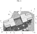
Figure 5 illustrates a partially cross-sectioned perspective view of some details illustrated in the preceding figures. - In the following description, various specific details are illustrated aimed at a thorough understanding of the embodiments. The embodiments can be implemented without one or more of the specific details, or with other methods, components, materials, etc. In other cases, known structures, constructive details, materials or operations are not illustrated and described in detail, since they can be produced in any known way and also because they do not fall within the scope of the present invention.
- In the present description and in the claims that follow, the term "additive manufacturing" means a method, known in the art, in which an energy source is used, such as a laser or plasma beam, to selectively melt layers of wires or powders of metal material or plastic material, of various sizes, so as to form layer after layer, a component of metal material or plastic material. For example, a device for making components using additive manufacturing is known from the
document EP 3 148 784 A1 . Of course, the technology illustrated in this document represents just one example, since different additive manufacturing technologies can be applied to produce the device according to the present invention. -
Figures 1-5 illustrate a preferred embodiment of a hinge of a motor-vehicle mobile part (for example, for a side door, a rear door or a bonnet) according to the present invention. - As shown in particular in
Figures 1 and 2 , the hinge comprises afirst hinge element 1 and asecond hinge element 2 mounted articulated with respect to one another about a hinge axis A. However, the present invention also relates to hinges having different configurations with respect to that illustrated in the attached drawings (for example, a double hinge with three mutually articulated elements, an articulated quadrilateral or a cardan joint). - In the case illustrated in the drawings, the
first hinge element 1 is arranged for connection to either a motor-vehicle structure or a mobile part of a motor-vehicle, while thesecond hinge element 2 is arranged for connection to the other of said motor-vehicle structure or said mobile part. To create the connection with the mobile part (for example, a side door) and the motor-vehicle structure, the twohinge elements connection bracket respective holes second hinge elements - With reference in particular to
Figures 3-5 , thesecond hinge element 2 is articulated to thefirst hinge element 1 by means of anarticulation portion 7 which includes a pair ofinner flanges 8 having respectiveouter sides 9, from which two pins P defining the hinge axis A protrude. The pins P are formed in one piece with thesecond hinge element 2, and project in opposite directions from the twosides 9 of thearticulation portion 7 of thesecond hinge element 2. - In accordance with an essential characteristic of the present invention, the
first hinge element 1 and thesecond hinge element 2 are obtained with an additive manufacturing technique in an already reciprocally articulated condition, wherein the pins P are mounted with clearance within respective articulation seats S of the first hinge element 1 (Figures 3, 4 ). More particularly, the articulation seats S of thefirst hinge element 1 are formed on twoflanges 6 that are adjacent to thesides 9 of theinner flanges 8 of thesecond hinge element 2, in such a way that the twohinge elements - By producing the motor-vehicle hinge by means of an additive manufacturing technique, it is possible to obtain numerous advantages with respect to traditional production methods, for example, providing components with complex geometries without incurring penalties in terms of time or cost with respect to the production of simpler geometrical components. In the case of the invention, the hinge can be made of metal or plastic material.
- Preferably, in order to reduce the overall weight of the hinge, a
central recess 16 is formed between the pair ofinner flanges 8 of thesecond hinge element 2. - According to another preferred characteristic of the present invention, the
second hinge element 2 has acentral portion 15, which joins theconnection bracket 11 to thearticulation portion 7, including ahollow portion 14. - As indicated above, the pins P - projecting in opposite directions from the sides 9 - are mounted with clearance within the respective articulation seats S formed on the
flanges 6 of thefirst hinge element 1. The twohinge elements flanges 6, on which the articulation seats S are formed, are adjacent to thesides 9 of theinner flanges 8 from which the pins P project. - In order to allow the pins P to perform a rotational movement only about the hinge axis A, the hinge according to the present invention also comprises two bushing-
shaped members 3, each interposed between a pin P and the respective articulation seat S. As illustrated in particular inFigures 3-5 , thebushing members 3, each comprising abase surface 4, aside wall 17 and anupper surface 5, are mounted by interference fit within the respective articulation seat S, so as to allow the respective pins P to rotate therein. - In the mounted condition illustrated in
Figures 1, 2 ,5 , thebase surface 4 of the bushing-shaped member 3 is arranged in abutment against arespective side 9 of thesecond hinge element 2, while theupper surface 5 of the bushing-shaped member 3 is adjacent to anouter side 18 of therespective flange 6 of thefirst hinge element 1. - Preferably, the bushing-
shaped members 3 are made of a material with a low friction coefficient, for example, bronze or a synthetic material. - Still according to a preferred characteristic, the
upper surface 5 of each bushing-shaped member 3 has a larger area than thebase surface 4, so as to provide a stable coupling with the respectiveouter side 18 of theflange 6 of thefirst hinge element 1. - Thanks to the above described characteristics of the motor-vehicle hinge according to the present invention, it is possible to produce, by means of a rapid and low-cost production method, two hinge elements permanently bound to each other, providing a structure with a simple geometry and low weight.
- In addition to that indicated above, one or more embodiments of the present invention may relate to a mobile part of a motor-vehicle (for example, a side door) with a motor-vehicle hinge, having the characteristics indicated above, pre-mounted to the mobile part by means of respective fastening members.
- Furthermore, one or more embodiments of the present invention may relate to a motor-vehicle body with a motor-vehicle hinge, having the characteristics indicated above, pre-mounted to the body by means of respective fastening members.
- As indicated in the attached claims, the invention also relates to a method for producing a motor-vehicle hinge comprising the following steps:
- producing a first hinge element and a second hinge element already reciprocally articulated with respect to each other about a hinge axis by means of an additive manufacturing technique, wherein the second hinge element is articulated to the first hinge element by means of an articulation portion having two pins defining the hinge axis and projecting in opposite directions from two sides of the articulation portion of the second hinge element, wherein said pins are mounted with clearance within respective articulation seats formed on two flanges of the first hinge element adjacent to said sides of the second hinge element, so that the two hinge elements are permanently bound to each other, and
- mounting two bushing-shaped members within a respective articulation seat of the first hinge element, in such a way that each bushing-shaped member is interposed between one of said two pins and the respective articulation seat.
- Of course, without prejudice to the principle of the invention, the details of construction and the embodiments may vary widely with respect to those described and illustrated purely by way of example, without departing from the scope of the present invention.
Claims (11)
- A hinge of a motor-vehicle mobile part, comprising at least the following elements:- a first hinge element (1) intended to be connected to either a mobile part of a motor-vehicle or a motor-vehicle structure,- a second hinge element (2) intended to be connected to the other of said motor-vehicle structure or said mobile part of the motor-vehicle,- wherein said first and second hinge elements (1,2) are mounted articulated with respect to each other about a hinge axis (A),- wherein said second hinge element (2) is articulated to said first hinge element (1) by means of an articulation portion (7) having two pins (P) defining the hinge axis (A) and projecting in opposite directions from two sides (9) of said articulation portion (7) of the second hinge element (2),- wherein said pins (P) are formed in a single piece with the second hinge element (2),- wherein the first hinge element (1) and the second hinge element (2) are obtained by an additive manufacturing technique in an already reciprocally articulated condition, with said pins (P) mounted with clearance within respective articulation seats (S) formed on two flanges (6) of the first hinge element (1) adjacent to said sides of the second hinge element, so that the two hinge elements (1, 2) are permanently bound to each other,- said hinge also comprising two bushing-shaped members (3), each interposed between one of said two pins (P) and the respective articulation seat (S).
- A hinge of a motor-vehicle mobile part according to claim 1, characterized in that said articulation portion (7) of the second hinge element (2) includes two inner flanges (8) that define said sides (9).
- A hinge of a motor-vehicle mobile part according to claim 2, characterized in that a central recess (16) is formed between the two inner flanges (8).
- A hinge of a motor-vehicle mobile part according to any one of the preceding claims, characterized in that said first and second hinge elements (1, 2) each comprise a connection bracket (10, 11) provided with respective holes (12, 13) for engaging with a plurality of fastening members, for connection to either a motor-vehicle structure or a mobile part of the motor-vehicle.
- A hinge of a motor-vehicle mobile part according to any of the preceding claims, characterized in that each bushing-shaped member (3) has a base surface (4), a side wall (17) and an upper surface (5), wherein:- said base surface (4) is arranged in abutment on a respective side (9) of the second hinge element (2),- said upper surface (5) is adjacent to an outer side (18) of the respective flange (6) of the first hinge element (1),- said side wall (17) is arranged between the pin (P) and the respective articulation seat (S),- said bushing-shaped member (3) is mounted by interference fit within the respective articulation seat (S), so as to allow the respective pins to rotate therein.
- A hinge of a motor-vehicle mobile part according to any one of the preceding claims, characterized in that said bushing-shaped members (3) are made of a material with a low friction coefficient.
- A hinge of a motor-vehicle mobile part according to any one of the preceding claims, characterized in that the second hinge element (2) has a central portion (15) which joins said bracket (11) to said articulation portion (7), including a central hollow portion (14).
- A mobile part of a motor-vehicle having a hinge according to any one of the preceding claims pre-assembled to said mobile part by means of respective fastening members.
- A body of a motor-vehicle including a hinge according to any one of the preceding claims pre-assembled to said body by means of respective fastening members.
- A motor-vehicle having at least one hinge according to any one of the preceding claims.
- A method for producing a motor-vehicle hinge comprising the following steps:- producing at least one first hinge element (1) and a second hinge element (2) already reciprocally articulated to each other about a hinge axis (A) by means of an additive manufacturing technique,- wherein said second hinge element (2) is articulated to said first hinge element (1) by means of an articulation portion (7) having two pins (P) defining the hinge axis (A) and projecting in opposite directions from two sides (9) of said articulation portion (7) of the second hinge element (2),- wherein said pins (P) are mounted with clearance within respective articulation seats (S) formed on two flanges (6) of the first hinge element (1) adjacent to said sides (9) of the second hinge element (2), so that the two hinge elements (1,2) are permanently bound to each other,- mounting two bushing-shaped members (3) within a respective articulation seat (S) in such a way that each bushing-shaped member (3) is interposed between one of said two pins (P) and the respective articulation seat (S).
Priority Applications (3)
| Application Number | Priority Date | Filing Date | Title |
|---|---|---|---|
| EP19188862.7A EP3771791B1 (en) | 2019-07-29 | 2019-07-29 | Hinge of motor-vehicle mobile part |
| US16/933,260 US11466490B2 (en) | 2019-07-29 | 2020-07-20 | Hinge of a motor-vehicle mobile part |
| CN202010744330.7A CN112302445B (en) | 2019-07-29 | 2020-07-29 | Hinge for a mobile part of a motor vehicle |
Applications Claiming Priority (1)
| Application Number | Priority Date | Filing Date | Title |
|---|---|---|---|
| EP19188862.7A EP3771791B1 (en) | 2019-07-29 | 2019-07-29 | Hinge of motor-vehicle mobile part |
Publications (2)
| Publication Number | Publication Date |
|---|---|
| EP3771791A1 true EP3771791A1 (en) | 2021-02-03 |
| EP3771791B1 EP3771791B1 (en) | 2022-01-19 |
Family
ID=67658252
Family Applications (1)
| Application Number | Title | Priority Date | Filing Date |
|---|---|---|---|
| EP19188862.7A Active EP3771791B1 (en) | 2019-07-29 | 2019-07-29 | Hinge of motor-vehicle mobile part |
Country Status (3)
| Country | Link |
|---|---|
| US (1) | US11466490B2 (en) |
| EP (1) | EP3771791B1 (en) |
| CN (1) | CN112302445B (en) |
Cited By (1)
| Publication number | Priority date | Publication date | Assignee | Title |
|---|---|---|---|---|
| US11390019B2 (en) * | 2019-12-13 | 2022-07-19 | Teco Image Systems Co., Ltd. | Additive manufacturing method and object manufactured thereby |
Families Citing this family (2)
| Publication number | Priority date | Publication date | Assignee | Title |
|---|---|---|---|---|
| DE102022105466B3 (en) * | 2022-03-08 | 2022-11-24 | Edscha Engineering Gmbh | automotive hinge |
| USD1049827S1 (en) * | 2024-07-01 | 2024-11-05 | Hongxia Liu | Mounting bracket |
Citations (4)
| Publication number | Priority date | Publication date | Assignee | Title |
|---|---|---|---|---|
| EP1043467A1 (en) | 1999-04-07 | 2000-10-11 | Gammastamp S.p.A. | Hinge for vehicle doors |
| WO2008006191A1 (en) * | 2006-07-10 | 2008-01-17 | Multimatic Inc. | Multiple piece construction automotive door hinge |
| EP3148784A1 (en) | 2014-05-30 | 2017-04-05 | PRIMA INDUSTRIE S.p.A. | Laser operating machine for additive manufacturing by laser sintering and corresponding method |
| US20170096847A1 (en) | 2015-10-02 | 2017-04-06 | UCT Additive Manufacturing Center Pte. Ltd. | Additive manufactured moveable parts |
Family Cites Families (21)
| Publication number | Priority date | Publication date | Assignee | Title |
|---|---|---|---|---|
| GB638798A (en) * | 1948-07-06 | 1950-06-14 | Standard Pressed Steel Co | Improvements in or relating to hinges |
| JP2534581B2 (en) * | 1990-11-30 | 1996-09-18 | 本田技研工業株式会社 | Method and apparatus for manufacturing automobile door |
| CA2277114C (en) * | 1999-07-07 | 2004-06-01 | Multimatic Inc. | Integrated door check hinge for automobiles |
| DE102006053197B3 (en) * | 2006-11-09 | 2008-02-07 | Automotive Group Ise Industries Hainichen Gmbh | Hinge for attaching e.g. door, at motor vehicle body, has door console and column console with contact surfaces formed by main and auxiliary partial surfaces and connecting area, where surfaces and area are differentiated from each other |
| DE102006056549B3 (en) * | 2006-11-29 | 2008-01-17 | Automotive Group Ise Innomotive Systems Europe Gmbh | Motor vehicle door hinge, with brackets at the door and the bodywork pillar, has a sliding bush in a bearing point to take a bolt which remains in place on dismantling |
| JP4894952B2 (en) * | 2009-09-10 | 2012-03-14 | トヨタ車体株式会社 | Hinge for vehicle door |
| US9103146B2 (en) * | 2013-07-26 | 2015-08-11 | Mitsui Kinzoku Act Corporation | Vehicle door hinge |
| US9180761B1 (en) * | 2014-05-02 | 2015-11-10 | GM Global Technology Operations LLC | Hinge assembly |
| JP6519002B2 (en) * | 2014-11-27 | 2019-05-29 | 三井金属アクト株式会社 | Vehicle door hinge and method of manufacturing the same |
| KR101714196B1 (en) * | 2015-08-24 | 2017-03-08 | 현대자동차주식회사 | Common Use Door Hinge for Automobile Door |
| ITUB20160405A1 (en) * | 2016-02-04 | 2017-08-04 | Fiat Ricerche | DOOR STRUCTURE FOR VEHICLE |
| US10184280B2 (en) * | 2016-06-02 | 2019-01-22 | Flex-N-Gate Advanced Product Development, Llc. | Automotive door hinge |
| US9933092B2 (en) * | 2016-08-18 | 2018-04-03 | Deflecto, LLC | Tubular structures and knurling systems and methods of manufacture and use thereof |
| JP6656220B2 (en) * | 2017-12-22 | 2020-03-04 | 本田技研工業株式会社 | Hinge mechanism |
| JP7106858B2 (en) * | 2017-12-26 | 2022-07-27 | トヨタ自動車株式会社 | Vehicle door hinge structure |
| DE102019105674B4 (en) * | 2018-03-09 | 2023-03-09 | Omix-Ada, Inc. | HINGE BRACKET SYSTEM FOR COMMERCIAL VEHICLES |
| JP7047237B2 (en) * | 2018-03-15 | 2022-04-05 | 三井金属アクト株式会社 | Manufacturing method of door hinges for automobiles and automobiles |
| US11408216B2 (en) * | 2018-03-20 | 2022-08-09 | Divergent Technologies, Inc. | Systems and methods for co-printed or concurrently assembled hinge structures |
| KR102565334B1 (en) * | 2018-12-10 | 2023-08-09 | 현대자동차주식회사 | Door hinge and manufacturing method of the same |
| US20220042362A1 (en) * | 2019-01-18 | 2022-02-10 | Warren Industries Ltd. | Vehicular door hinge with folded sheet metal component |
| US20200284078A1 (en) * | 2019-03-08 | 2020-09-10 | Volvo Car Corporation | Adjustable hinge assembly for automobile tailgate |
-
2019
- 2019-07-29 EP EP19188862.7A patent/EP3771791B1/en active Active
-
2020
- 2020-07-20 US US16/933,260 patent/US11466490B2/en active Active
- 2020-07-29 CN CN202010744330.7A patent/CN112302445B/en active Active
Patent Citations (4)
| Publication number | Priority date | Publication date | Assignee | Title |
|---|---|---|---|---|
| EP1043467A1 (en) | 1999-04-07 | 2000-10-11 | Gammastamp S.p.A. | Hinge for vehicle doors |
| WO2008006191A1 (en) * | 2006-07-10 | 2008-01-17 | Multimatic Inc. | Multiple piece construction automotive door hinge |
| EP3148784A1 (en) | 2014-05-30 | 2017-04-05 | PRIMA INDUSTRIE S.p.A. | Laser operating machine for additive manufacturing by laser sintering and corresponding method |
| US20170096847A1 (en) | 2015-10-02 | 2017-04-06 | UCT Additive Manufacturing Center Pte. Ltd. | Additive manufactured moveable parts |
Non-Patent Citations (1)
| Title |
|---|
| ADAFRUIT INDUSTRIES: "Fusion 360 Tutorial - Print-In-Place Hinge - Layer by Layer", YOUTUBE, 24 January 2019 (2019-01-24), pages 2 pp., XP054980167, Retrieved from the Internet <URL:https://www.youtube.com/watch?v=M6AqZDajXHM> [retrieved on 20200127] * |
Cited By (1)
| Publication number | Priority date | Publication date | Assignee | Title |
|---|---|---|---|---|
| US11390019B2 (en) * | 2019-12-13 | 2022-07-19 | Teco Image Systems Co., Ltd. | Additive manufacturing method and object manufactured thereby |
Also Published As
| Publication number | Publication date |
|---|---|
| EP3771791B1 (en) | 2022-01-19 |
| CN112302445B (en) | 2023-05-02 |
| CN112302445A (en) | 2021-02-02 |
| US11466490B2 (en) | 2022-10-11 |
| US20210032915A1 (en) | 2021-02-04 |
Similar Documents
| Publication | Publication Date | Title |
|---|---|---|
| US11466490B2 (en) | Hinge of a motor-vehicle mobile part | |
| US6622450B2 (en) | Roll-formed and stamped doorbeam | |
| US20100264271A1 (en) | Fittings for attaching the vertical tail stabilizer of an aircraft | |
| EP0722401A1 (en) | End section of frame member | |
| CN104421259A (en) | Elastically deformable alignment fastener and system | |
| CN108691470A (en) | Double pivot transverse translation hinges | |
| JP2009542942A (en) | Multi-part automotive door hinge | |
| CN112406437B (en) | Chassis control arm and method for manufacturing chassis control arm | |
| EP0745172A1 (en) | Snap hinge | |
| CA2520296C (en) | Low-profile high-strength vehicle door beam | |
| WO2014123113A1 (en) | Door hinge for automobile and method for manufacturing first bracket thereof | |
| JP2007196826A (en) | Vehicle rear door structure | |
| GB2329672A (en) | Lock block for a vehicle locking system | |
| CA2483425A1 (en) | Suspension and axle assembly | |
| JP6218016B2 (en) | Vehicle door structure | |
| JP2001055044A (en) | Hollow body supporting arm for swing hinge | |
| US10053900B2 (en) | Center track design for a sliding door | |
| US7296325B1 (en) | Hinge members and hinge assemblies | |
| CN205853848U (en) | Tail-gate inner panel, tail-gate and vehicle | |
| JP5708428B2 (en) | Vehicle back door structure | |
| GB2215775A (en) | Hinges | |
| US2153734A (en) | Hinge | |
| EP3165447B1 (en) | Aircraft fuselage structure | |
| US20060267373A1 (en) | Motor vehicle door hinge for pivotal fitting of a vehicle door to a vehicle body | |
| JP5857679B2 (en) | Trunk lid mounting vehicle structure |
Legal Events
| Date | Code | Title | Description |
|---|---|---|---|
| PUAI | Public reference made under article 153(3) epc to a published international application that has entered the european phase |
Free format text: ORIGINAL CODE: 0009012 |
|
| STAA | Information on the status of an ep patent application or granted ep patent |
Free format text: STATUS: REQUEST FOR EXAMINATION WAS MADE |
|
| 17P | Request for examination filed |
Effective date: 20200320 |
|
| AK | Designated contracting states |
Kind code of ref document: A1 Designated state(s): AL AT BE BG CH CY CZ DE DK EE ES FI FR GB GR HR HU IE IS IT LI LT LU LV MC MK MT NL NO PL PT RO RS SE SI SK SM TR |
|
| AX | Request for extension of the european patent |
Extension state: BA ME |
|
| GRAP | Despatch of communication of intention to grant a patent |
Free format text: ORIGINAL CODE: EPIDOSNIGR1 |
|
| STAA | Information on the status of an ep patent application or granted ep patent |
Free format text: STATUS: GRANT OF PATENT IS INTENDED |
|
| INTG | Intention to grant announced |
Effective date: 20210914 |
|
| RIN1 | Information on inventor provided before grant (corrected) |
Inventor name: CARCIOFFI, CARLO Inventor name: PARADISO, STEFANO Inventor name: LONGO, MICHELE Inventor name: SANDRI, SILVANO Inventor name: BASSAN, DANIELE |
|
| GRAS | Grant fee paid |
Free format text: ORIGINAL CODE: EPIDOSNIGR3 |
|
| GRAA | (expected) grant |
Free format text: ORIGINAL CODE: 0009210 |
|
| STAA | Information on the status of an ep patent application or granted ep patent |
Free format text: STATUS: THE PATENT HAS BEEN GRANTED |
|
| AK | Designated contracting states |
Kind code of ref document: B1 Designated state(s): AL AT BE BG CH CY CZ DE DK EE ES FI FR GB GR HR HU IE IS IT LI LT LU LV MC MK MT NL NO PL PT RO RS SE SI SK SM TR |
|
| REG | Reference to a national code |
Ref country code: GB Ref legal event code: FG4D |
|
| REG | Reference to a national code |
Ref country code: CH Ref legal event code: EP |
|
| REG | Reference to a national code |
Ref country code: AT Ref legal event code: REF Ref document number: 1463896 Country of ref document: AT Kind code of ref document: T Effective date: 20220215 |
|
| REG | Reference to a national code |
Ref country code: IE Ref legal event code: FG4D |
|
| REG | Reference to a national code |
Ref country code: DE Ref legal event code: R096 Ref document number: 602019010996 Country of ref document: DE |
|
| REG | Reference to a national code |
Ref country code: LT Ref legal event code: MG9D |
|
| REG | Reference to a national code |
Ref country code: NL Ref legal event code: MP Effective date: 20220119 |
|
| REG | Reference to a national code |
Ref country code: AT Ref legal event code: MK05 Ref document number: 1463896 Country of ref document: AT Kind code of ref document: T Effective date: 20220119 |
|
| PG25 | Lapsed in a contracting state [announced via postgrant information from national office to epo] |
Ref country code: NL Free format text: LAPSE BECAUSE OF FAILURE TO SUBMIT A TRANSLATION OF THE DESCRIPTION OR TO PAY THE FEE WITHIN THE PRESCRIBED TIME-LIMIT Effective date: 20220119 |
|
| PG25 | Lapsed in a contracting state [announced via postgrant information from national office to epo] |
Ref country code: SE Free format text: LAPSE BECAUSE OF FAILURE TO SUBMIT A TRANSLATION OF THE DESCRIPTION OR TO PAY THE FEE WITHIN THE PRESCRIBED TIME-LIMIT Effective date: 20220119 Ref country code: RS Free format text: LAPSE BECAUSE OF FAILURE TO SUBMIT A TRANSLATION OF THE DESCRIPTION OR TO PAY THE FEE WITHIN THE PRESCRIBED TIME-LIMIT Effective date: 20220119 Ref country code: PT Free format text: LAPSE BECAUSE OF FAILURE TO SUBMIT A TRANSLATION OF THE DESCRIPTION OR TO PAY THE FEE WITHIN THE PRESCRIBED TIME-LIMIT Effective date: 20220519 Ref country code: NO Free format text: LAPSE BECAUSE OF FAILURE TO SUBMIT A TRANSLATION OF THE DESCRIPTION OR TO PAY THE FEE WITHIN THE PRESCRIBED TIME-LIMIT Effective date: 20220419 Ref country code: LT Free format text: LAPSE BECAUSE OF FAILURE TO SUBMIT A TRANSLATION OF THE DESCRIPTION OR TO PAY THE FEE WITHIN THE PRESCRIBED TIME-LIMIT Effective date: 20220119 Ref country code: HR Free format text: LAPSE BECAUSE OF FAILURE TO SUBMIT A TRANSLATION OF THE DESCRIPTION OR TO PAY THE FEE WITHIN THE PRESCRIBED TIME-LIMIT Effective date: 20220119 Ref country code: ES Free format text: LAPSE BECAUSE OF FAILURE TO SUBMIT A TRANSLATION OF THE DESCRIPTION OR TO PAY THE FEE WITHIN THE PRESCRIBED TIME-LIMIT Effective date: 20220119 Ref country code: BG Free format text: LAPSE BECAUSE OF FAILURE TO SUBMIT A TRANSLATION OF THE DESCRIPTION OR TO PAY THE FEE WITHIN THE PRESCRIBED TIME-LIMIT Effective date: 20220419 |
|
| PG25 | Lapsed in a contracting state [announced via postgrant information from national office to epo] |
Ref country code: PL Free format text: LAPSE BECAUSE OF FAILURE TO SUBMIT A TRANSLATION OF THE DESCRIPTION OR TO PAY THE FEE WITHIN THE PRESCRIBED TIME-LIMIT Effective date: 20220119 Ref country code: LV Free format text: LAPSE BECAUSE OF FAILURE TO SUBMIT A TRANSLATION OF THE DESCRIPTION OR TO PAY THE FEE WITHIN THE PRESCRIBED TIME-LIMIT Effective date: 20220119 Ref country code: GR Free format text: LAPSE BECAUSE OF FAILURE TO SUBMIT A TRANSLATION OF THE DESCRIPTION OR TO PAY THE FEE WITHIN THE PRESCRIBED TIME-LIMIT Effective date: 20220420 Ref country code: FI Free format text: LAPSE BECAUSE OF FAILURE TO SUBMIT A TRANSLATION OF THE DESCRIPTION OR TO PAY THE FEE WITHIN THE PRESCRIBED TIME-LIMIT Effective date: 20220119 Ref country code: AT Free format text: LAPSE BECAUSE OF FAILURE TO SUBMIT A TRANSLATION OF THE DESCRIPTION OR TO PAY THE FEE WITHIN THE PRESCRIBED TIME-LIMIT Effective date: 20220119 |
|
| PG25 | Lapsed in a contracting state [announced via postgrant information from national office to epo] |
Ref country code: IS Free format text: LAPSE BECAUSE OF FAILURE TO SUBMIT A TRANSLATION OF THE DESCRIPTION OR TO PAY THE FEE WITHIN THE PRESCRIBED TIME-LIMIT Effective date: 20220519 |
|
| REG | Reference to a national code |
Ref country code: DE Ref legal event code: R097 Ref document number: 602019010996 Country of ref document: DE |
|
| PG25 | Lapsed in a contracting state [announced via postgrant information from national office to epo] |
Ref country code: SM Free format text: LAPSE BECAUSE OF FAILURE TO SUBMIT A TRANSLATION OF THE DESCRIPTION OR TO PAY THE FEE WITHIN THE PRESCRIBED TIME-LIMIT Effective date: 20220119 Ref country code: SK Free format text: LAPSE BECAUSE OF FAILURE TO SUBMIT A TRANSLATION OF THE DESCRIPTION OR TO PAY THE FEE WITHIN THE PRESCRIBED TIME-LIMIT Effective date: 20220119 Ref country code: RO Free format text: LAPSE BECAUSE OF FAILURE TO SUBMIT A TRANSLATION OF THE DESCRIPTION OR TO PAY THE FEE WITHIN THE PRESCRIBED TIME-LIMIT Effective date: 20220119 Ref country code: EE Free format text: LAPSE BECAUSE OF FAILURE TO SUBMIT A TRANSLATION OF THE DESCRIPTION OR TO PAY THE FEE WITHIN THE PRESCRIBED TIME-LIMIT Effective date: 20220119 Ref country code: DK Free format text: LAPSE BECAUSE OF FAILURE TO SUBMIT A TRANSLATION OF THE DESCRIPTION OR TO PAY THE FEE WITHIN THE PRESCRIBED TIME-LIMIT Effective date: 20220119 Ref country code: CZ Free format text: LAPSE BECAUSE OF FAILURE TO SUBMIT A TRANSLATION OF THE DESCRIPTION OR TO PAY THE FEE WITHIN THE PRESCRIBED TIME-LIMIT Effective date: 20220119 |
|
| PLBE | No opposition filed within time limit |
Free format text: ORIGINAL CODE: 0009261 |
|
| STAA | Information on the status of an ep patent application or granted ep patent |
Free format text: STATUS: NO OPPOSITION FILED WITHIN TIME LIMIT |
|
| PG25 | Lapsed in a contracting state [announced via postgrant information from national office to epo] |
Ref country code: AL Free format text: LAPSE BECAUSE OF FAILURE TO SUBMIT A TRANSLATION OF THE DESCRIPTION OR TO PAY THE FEE WITHIN THE PRESCRIBED TIME-LIMIT Effective date: 20220119 |
|
| 26N | No opposition filed |
Effective date: 20221020 |
|
| PG25 | Lapsed in a contracting state [announced via postgrant information from national office to epo] |
Ref country code: SI Free format text: LAPSE BECAUSE OF FAILURE TO SUBMIT A TRANSLATION OF THE DESCRIPTION OR TO PAY THE FEE WITHIN THE PRESCRIBED TIME-LIMIT Effective date: 20220119 Ref country code: MC Free format text: LAPSE BECAUSE OF FAILURE TO SUBMIT A TRANSLATION OF THE DESCRIPTION OR TO PAY THE FEE WITHIN THE PRESCRIBED TIME-LIMIT Effective date: 20220119 |
|
| REG | Reference to a national code |
Ref country code: CH Ref legal event code: PL |
|
| REG | Reference to a national code |
Ref country code: BE Ref legal event code: MM Effective date: 20220731 |
|
| PG25 | Lapsed in a contracting state [announced via postgrant information from national office to epo] |
Ref country code: LU Free format text: LAPSE BECAUSE OF NON-PAYMENT OF DUE FEES Effective date: 20220729 Ref country code: LI Free format text: LAPSE BECAUSE OF NON-PAYMENT OF DUE FEES Effective date: 20220731 Ref country code: CH Free format text: LAPSE BECAUSE OF NON-PAYMENT OF DUE FEES Effective date: 20220731 |
|
| PG25 | Lapsed in a contracting state [announced via postgrant information from national office to epo] |
Ref country code: BE Free format text: LAPSE BECAUSE OF NON-PAYMENT OF DUE FEES Effective date: 20220731 |
|
| PG25 | Lapsed in a contracting state [announced via postgrant information from national office to epo] |
Ref country code: IE Free format text: LAPSE BECAUSE OF NON-PAYMENT OF DUE FEES Effective date: 20220729 |
|
| GBPC | Gb: european patent ceased through non-payment of renewal fee |
Effective date: 20230729 |
|
| PG25 | Lapsed in a contracting state [announced via postgrant information from national office to epo] |
Ref country code: MK Free format text: LAPSE BECAUSE OF FAILURE TO SUBMIT A TRANSLATION OF THE DESCRIPTION OR TO PAY THE FEE WITHIN THE PRESCRIBED TIME-LIMIT Effective date: 20220119 Ref country code: CY Free format text: LAPSE BECAUSE OF FAILURE TO SUBMIT A TRANSLATION OF THE DESCRIPTION OR TO PAY THE FEE WITHIN THE PRESCRIBED TIME-LIMIT Effective date: 20220119 Ref country code: GB Free format text: LAPSE BECAUSE OF NON-PAYMENT OF DUE FEES Effective date: 20230729 |
|
| PG25 | Lapsed in a contracting state [announced via postgrant information from national office to epo] |
Ref country code: HU Free format text: LAPSE BECAUSE OF FAILURE TO SUBMIT A TRANSLATION OF THE DESCRIPTION OR TO PAY THE FEE WITHIN THE PRESCRIBED TIME-LIMIT; INVALID AB INITIO Effective date: 20190729 |
|
| PG25 | Lapsed in a contracting state [announced via postgrant information from national office to epo] |
Ref country code: MT Free format text: LAPSE BECAUSE OF FAILURE TO SUBMIT A TRANSLATION OF THE DESCRIPTION OR TO PAY THE FEE WITHIN THE PRESCRIBED TIME-LIMIT Effective date: 20220119 |
|
| PGFP | Annual fee paid to national office [announced via postgrant information from national office to epo] |
Ref country code: FR Payment date: 20250620 Year of fee payment: 7 |
|
| PGFP | Annual fee paid to national office [announced via postgrant information from national office to epo] |
Ref country code: DE Payment date: 20250620 Year of fee payment: 7 |
|
| PGFP | Annual fee paid to national office [announced via postgrant information from national office to epo] |
Ref country code: IT Payment date: 20250619 Year of fee payment: 7 |
|
| PG25 | Lapsed in a contracting state [announced via postgrant information from national office to epo] |
Ref country code: TR Free format text: LAPSE BECAUSE OF FAILURE TO SUBMIT A TRANSLATION OF THE DESCRIPTION OR TO PAY THE FEE WITHIN THE PRESCRIBED TIME-LIMIT Effective date: 20220119 |