EP3771571A1 - Thermal printer - Google Patents
Thermal printer Download PDFInfo
- Publication number
- EP3771571A1 EP3771571A1 EP20188865.8A EP20188865A EP3771571A1 EP 3771571 A1 EP3771571 A1 EP 3771571A1 EP 20188865 A EP20188865 A EP 20188865A EP 3771571 A1 EP3771571 A1 EP 3771571A1
- Authority
- EP
- European Patent Office
- Prior art keywords
- recording sheet
- separation wall
- thermal printer
- rolling start
- guide
- Prior art date
- Legal status (The legal status is an assumption and is not a legal conclusion. Google has not performed a legal analysis and makes no representation as to the accuracy of the status listed.)
- Granted
Links
Images







Classifications
-
- B—PERFORMING OPERATIONS; TRANSPORTING
- B41—PRINTING; LINING MACHINES; TYPEWRITERS; STAMPS
- B41J—TYPEWRITERS; SELECTIVE PRINTING MECHANISMS, i.e. MECHANISMS PRINTING OTHERWISE THAN FROM A FORME; CORRECTION OF TYPOGRAPHICAL ERRORS
- B41J15/00—Devices or arrangements of selective printing mechanisms, e.g. ink-jet printers or thermal printers, specially adapted for supporting or handling copy material in continuous form, e.g. webs
- B41J15/04—Supporting, feeding, or guiding devices; Mountings for web rolls or spindles
- B41J15/042—Supporting, feeding, or guiding devices; Mountings for web rolls or spindles for loading rolled-up continuous copy material into printers, e.g. for replacing a used-up paper roll; Point-of-sale printers with openable casings allowing access to the rolled-up continuous copy material
-
- B—PERFORMING OPERATIONS; TRANSPORTING
- B41—PRINTING; LINING MACHINES; TYPEWRITERS; STAMPS
- B41J—TYPEWRITERS; SELECTIVE PRINTING MECHANISMS, i.e. MECHANISMS PRINTING OTHERWISE THAN FROM A FORME; CORRECTION OF TYPOGRAPHICAL ERRORS
- B41J2/00—Typewriters or selective printing mechanisms characterised by the printing or marking process for which they are designed
- B41J2/315—Typewriters or selective printing mechanisms characterised by the printing or marking process for which they are designed characterised by selective application of heat to a heat sensitive printing or impression-transfer material
- B41J2/32—Typewriters or selective printing mechanisms characterised by the printing or marking process for which they are designed characterised by selective application of heat to a heat sensitive printing or impression-transfer material using thermal heads
-
- B—PERFORMING OPERATIONS; TRANSPORTING
- B41—PRINTING; LINING MACHINES; TYPEWRITERS; STAMPS
- B41J—TYPEWRITERS; SELECTIVE PRINTING MECHANISMS, i.e. MECHANISMS PRINTING OTHERWISE THAN FROM A FORME; CORRECTION OF TYPOGRAPHICAL ERRORS
- B41J11/00—Devices or arrangements of selective printing mechanisms, e.g. ink-jet printers or thermal printers, for supporting or handling copy material in sheet or web form
- B41J11/006—Means for preventing paper jams or for facilitating their removal
-
- B—PERFORMING OPERATIONS; TRANSPORTING
- B41—PRINTING; LINING MACHINES; TYPEWRITERS; STAMPS
- B41J—TYPEWRITERS; SELECTIVE PRINTING MECHANISMS, i.e. MECHANISMS PRINTING OTHERWISE THAN FROM A FORME; CORRECTION OF TYPOGRAPHICAL ERRORS
- B41J11/00—Devices or arrangements of selective printing mechanisms, e.g. ink-jet printers or thermal printers, for supporting or handling copy material in sheet or web form
- B41J11/02—Platens
- B41J11/04—Roller platens
-
- B—PERFORMING OPERATIONS; TRANSPORTING
- B41—PRINTING; LINING MACHINES; TYPEWRITERS; STAMPS
- B41J—TYPEWRITERS; SELECTIVE PRINTING MECHANISMS, i.e. MECHANISMS PRINTING OTHERWISE THAN FROM A FORME; CORRECTION OF TYPOGRAPHICAL ERRORS
- B41J2/00—Typewriters or selective printing mechanisms characterised by the printing or marking process for which they are designed
- B41J2/315—Typewriters or selective printing mechanisms characterised by the printing or marking process for which they are designed characterised by selective application of heat to a heat sensitive printing or impression-transfer material
- B41J2/32—Typewriters or selective printing mechanisms characterised by the printing or marking process for which they are designed characterised by selective application of heat to a heat sensitive printing or impression-transfer material using thermal heads
- B41J2/335—Structure of thermal heads
- B41J2/3355—Structure of thermal heads characterised by materials
-
- B—PERFORMING OPERATIONS; TRANSPORTING
- B41—PRINTING; LINING MACHINES; TYPEWRITERS; STAMPS
- B41J—TYPEWRITERS; SELECTIVE PRINTING MECHANISMS, i.e. MECHANISMS PRINTING OTHERWISE THAN FROM A FORME; CORRECTION OF TYPOGRAPHICAL ERRORS
- B41J29/00—Details of, or accessories for, typewriters or selective printing mechanisms not otherwise provided for
- B41J29/12—Guards, shields or dust excluders
- B41J29/13—Cases or covers
-
- B—PERFORMING OPERATIONS; TRANSPORTING
- B65—CONVEYING; PACKING; STORING; HANDLING THIN OR FILAMENTARY MATERIAL
- B65H—HANDLING THIN OR FILAMENTARY MATERIAL, e.g. SHEETS, WEBS, CABLES
- B65H41/00—Machines for separating superposed webs
-
- B—PERFORMING OPERATIONS; TRANSPORTING
- B41—PRINTING; LINING MACHINES; TYPEWRITERS; STAMPS
- B41J—TYPEWRITERS; SELECTIVE PRINTING MECHANISMS, i.e. MECHANISMS PRINTING OTHERWISE THAN FROM A FORME; CORRECTION OF TYPOGRAPHICAL ERRORS
- B41J2202/00—Embodiments of or processes related to ink-jet or thermal heads
- B41J2202/30—Embodiments of or processes related to thermal heads
- B41J2202/31—Thermal printer with head or platen movable
-
- B—PERFORMING OPERATIONS; TRANSPORTING
- B65—CONVEYING; PACKING; STORING; HANDLING THIN OR FILAMENTARY MATERIAL
- B65H—HANDLING THIN OR FILAMENTARY MATERIAL, e.g. SHEETS, WEBS, CABLES
- B65H2801/00—Application field
- B65H2801/03—Image reproduction devices
Definitions
- the present invention relates to a thermal printer.
- a printer configured to print predetermined information on a recording sheet as represented by, for example, a thermal printer
- a recording sheet obtained by rolling heat-sensitive paper into a roll shape around a core body is used (see, for example, Patent Literature 1).
- a recording-sheet sensor configured to detect presence or absence of the recording sheet is provided at a position on an upstream side of the heat-generating element. Further, at the position of the recording-sheet sensor on a path of the recording sheet, in order to more reliably detect the presence or absence of the recording sheet, a gap is regulated to be narrow in a thickness direction of the recording sheet.
- the recording sheet rolled into the roll shape be formed such that a leading edge 100a of a recording sheet 100 is formed into a turn-back shape of turning back in a direction opposite to a rolling direction at a rolling start portion 102 of the recording sheet 100, which is a portion of starting rolling around a shaft portion (core; core body) - in other words, where the leading edge of the recording sheet starts to be rolled around the shaft portion.
- the rolling start portion 102 is inside the roll near the shaft and is printed on when the roll has run out or is near running out.
- the leading edge that is rolled around the shaft portion may be considered to become the trailing edge.
- a detection signal of the sensor remains in a state of indicating the presence of the recording sheet, and printing processing with use of the heat-generating element is continued. Meanwhile, the sheet feeding cannot be performed, and hence a receipt or the like cannot be issued. In particular, occurrence of the circumstance described above in an automatic teller machine (ATM) or an unmanned terminal provided in a kiosk may cause serious problems in terms of both business and trust. Further, when such a state continues for a long period of time, the printing processing with the use of the heat-generating element is performed at the same position on the recording sheet 100. As a result, heat stays in the heat-generating element, which may cause defects such as thermal destruction of the heat-generating element and poor printing due to an increase in resistance value.
- ATM automatic teller machine
- a thermal printer including: a head unit including a thermal head configured to perform printing on a recording sheet; a platen unit, which includes a platen roller configured to convey the recording sheet, and is separably combined with the head unit; a printer main body, which has a recording-sheet receiving portion configured to receive the recording sheet, and has the head unit mounted thereto; a printer cover, which has the platen unit mounted thereto, and is coupled to the printer main body so as to be pivotable; and a separator, which is provided in the recording-sheet receiving portion, and is configured to separate parts of the recording sheet, which is rolled into a roll shape around a core body, folded on each other at a rolling start portion, which is rolled around the core body and has a turn-back shape.
- the separator includes a first separation wall which is provided at a position at which, when the rolling start portion of the recording sheet is unrolled, at least a part of a peripheral surface of the rolling start portion is brought into abutment along with a repulsive force generated by the stiffness of the recording sheet.
- the first separation wall is provided so as to pressurize at least a part of the peripheral surface of the rolling start portion of the recording sheet.
- the first separation wall includes a frictional-resistance member at a position at which at least a part of a peripheral surface of the rolling start portion of the recording sheet is brought into abutment.
- the first separation wall includes a locking portion configured to lock an end portion formed into a turn-back shape at the rolling start portion at a position at which at least a part of a peripheral surface of the rolling start portion of the recording sheet is brought into abutment.
- the first separation wall is mounted to the printer cover.
- the separator further includes a second separation wall which is provided at a position of being opposed to the first separation wall across the unrolled recording sheet and at which at least a part of the peripheral surface of the rolling start portion is brought into abutment along with a repulsive force generated by the stiffness of the recording sheet when the rolling start portion of the recording sheet is unrolled.
- the second separation wall includes a frictional-resistance member at a position at which at least a part of a peripheral surface of the rolling start portion of the recording sheet is brought into abutment.
- the second separation wall includes a locking portion configured to lock an end portion formed into a turn-back shape at the rolling start portion at a position at which at least a part of a peripheral surface of the rolling start portion of the recording sheet is brought into abutment.
- the second separation wall is mounted to the printer main body.
- the separator further includes a guide portion, which is located at a position of being opposed to the second separation wall across the unrolled recording sheet in the platen unit and in the vicinity of an inlet of a gap portion to which the recording sheet is conveyed, and is configured to guide the recording sheet.
- the guide portion is formed of a guide shaft which is in parallel with the core body of the recording sheet and is pivotable.
- the guide portion is formed of a guide wall which projects so as to be opposed to the second separation wall.
- the separator further includes a tension bar, which is located at a position of being opposed to the first separation wall across the unrolled recording sheet, and is configured to guide the recording sheet toward the first separation wall side.
- the thermal printer further includes a locking portion, which is provided on at least a part of a surface of the tension bar, and is configured to lock an end portion of the recording sheet at the rolling start portion formed into the turn-back shape.
- the separator includes: a tension bar, which is provided at a position of being opposed to the platen unit across the unrolled recording sheet, and is configured to guide the recording sheet toward the platen unit side; a guide portion, which is provided so as to be opposed to the tension bar at a position in the vicinity of an inlet of a gap portion to which the recording sheet is conveyed in the platen unit, and against which the recording sheet guided toward the platen unit side by the tension bar is brought into abutment; and a third separation wall, which is provided on a side opposite to the guide portion across the guide portion in the vicinity of an inlet of the gap portion, and against which at least a part of the recording sheet guided by the tension bar and the guide portion is brought into abutment, wherein a distal end of the tension bar and a distal end of the guide portion are arranged so as to overlap each other in a direction in which the platen unit and the tension bar are opposed to each other
- the third separation wall includes a locking portion configured to lock an end portion formed into a turn-back shape at the rolling start portion at a position at which at least a part of a peripheral surface of the rolling start portion of the recording sheet is brought into abutment.
- the separator includes: a tension bar configured to guide the recording sheet toward the platen unit side at a position of being opposed to the platen unit across the unrolled recording sheet; a fourth separation wall, which is arranged between the platen unit and the tension bar, and is configured to guide the recording sheet between the fourth separation wall and the tension bar; and a third separation wall, which is provided in the vicinity of an inlet of the gap portion, and against which at least a part of the recording sheet guided by the tension bar and the fourth separation wall is brought into abutment.
- the fourth separation wall is mounted to the printer cover.
- the separator is formed of a pair of guide rolls which are provided so as to pressurize the recording sheet so that at least a part of the recording sheet is brought into abutment against a frictional-resistance member when the rolling start portion of the recording sheet is unrolled.
- thermal printer of the present invention is given by way of example only, and configurations thereof are described in detail with reference to FIG. 1 to FIG. 16C .
- characteristic portions are enlarged in some cases, and may be different, for example, in dimensions and ratios of elements from those of actual products in some cases.
- materials, dimensions, and the like to be exemplified in the following description are examples.
- the present invention is not limited to those examples, and can be practiced with suitable modifications within the range of not modifying the gist of the present invention.
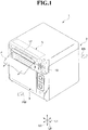
- FIG. 1 is a perspective view for illustrating a thermal printer 1 according to this embodiment in a state in which a printer cover 3 is closed.
- FIG. 2 is a perspective view for illustrating a state in which the printer cover 3 is opened.
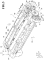
- FIG. 3 is a perspective view for illustrating a head unit 5 and a platen unit 4 provided to the thermal printer 1 according to this embodiment.
- the thermal printer 1 is a small-sized thermal printer that is to be used for printing tickets of various types, for example, at an ATM or an unmanned terminal provided in a kiosk or at a convenience store. That is, the thermal printer 1 is a printer (terminal) which is configured to perform thermal printing on a recording sheet (for example, heat-sensitive paper) 100 pulled out from a roll sheet R so that the recording sheet 100 can be used as, for example, a ticket or a receipt.
- a recording sheet for example, heat-sensitive paper
- the thermal printer 1 includes a casing (printer main body) 2, the printer cover 3, the platen unit 4 provided on the printer cover 3 side, and the head unit 5 provided on the casing 2 side. Further, in this embodiment, the platen unit 4 and the head unit 5 form a printing unit 8.
- a lower left side (printer cover 3 side) of a drawing sheet is defined as a forward side (direction of the arrow FW), an upper right side (casing 2 side) thereof is defined as a backward side (direction of the arrow BA), an upper side thereof is defined as an upward side, and a lower side thereof is defined as a downward side.
- a recording sheet P is delivered to the forward side FW.
- a direction orthogonal to a front-and-back direction L1 and an up-and-down direction L2 is defined as a right-and-left direction L3.
- the thermal printer 1 includes the printing unit 8 which is formed of the head unit 5 and the platen unit 4.
- the head unit 5 includes a thermal head (not shown) configured to perform printing on the recording sheet 100.
- the platen unit 4 includes a platen roller 33 configured to convey the recording sheet, and is separably combined with the head unit 5.
- the thermal printer 1 has a recording-sheet receiving portion 10 configured to receive the recording sheet 100, and mainly includes the casing 2 and the printer cover 3.
- the casing 2 has the head unit 5 mounted thereto.
- the printer cover 3 has the platen unit 4 mounted thereto, and is coupled to the casing 2 so as to be pivotable.
- the thermal printer 1 includes a first separation wall (separator) 80 in the recording-sheet receiving portion 10.
- the first separation wall 80 is configured to separate parts of the recording sheet 100 (roll sheet R), which is rolled into a roll shape around a core body 101, folded on each other at a rolling start portion 102, which is rolled around the core body 101 and has a turn-back shape.
- roll sheet R the recording sheet 100
- the casing (printer main body) 2 is made of, for example, a resin material, a metal material, or an appropriate combination thereof, and is formed into a cube shape opened on the forward side FW.
- a shape of the casing 2 is not limited to the shape given in the illustrated example, and may be suitably changed in consideration of design and size.
- the casing 2 includes, for example, a frame body serving as a basic skeleton, and an exterior cover for covering the frame body.
- the recording-sheet receiving portion 10 configured to receive the roll sheet R is formed in the casing 2, and the recording-sheet receiving portion 10 is opened to the forward side FW by opening the printer cover 3.
- the recording-sheet receiving portion 10 has a box shape that is formed of a part of the above-mentioned frame body (not shown) and is opened to the forward side FW.
- the recording-sheet receiving portion 10 is configured to receive the roll sheet R on an inner side thereof under a state in which a width direction of the roll sheet R is matched with the right-and-left direction L3.
- a first pivot shaft 11 extending along the right-and-left direction L3 is arranged in a lower portion of an opening edge of the casing 2.
- the printer cover 3 is coupled to the first pivot shaft 11 so as to be pivotable with respect to the casing 2.
- the printer cover 3 pivots within an angle range of about 90° between the closed position (position illustrated in FIG. 1 ) at which an opening portion of the casing 2 is closed and the open position (position illustrated in FIG. 2 ) at which the opening portion of the casing 2 is opened.
- the opening portion of the casing 2 that is, the recording-sheet receiving portion 10) is opened and closed by the printer cover 3.
- the recording-sheet receiving portion 10 is opened, and for example, the roll sheet R can be loaded into the recording-sheet receiving portion 10, and the thermal printer 1 is formed of so-called drop-in system.
- the thermal printer 1 has a configuration in which a slight gap is formed between a distal end portion of the printer cover 3 and the casing 2 when the printer cover 3 is located at the closed position.
- the recording sheet 100 is pulled out from an inner portion of the casing 2 to the forward side FW through use of the gap. Accordingly, the "slight gap" described above serves as a delivery port 12 of the recording sheet 100.
- the casing 2 and the printer cover 3 are locked with each other along with combination of the platen unit 4 and the head unit 5. Further, of corner portions positioned on an upper front side of the casing 2, the corner portion positioned on one side in the right-and-left direction L3 is provided with an operation lever 13 configured to release the combination (locking state) between the platen unit 4 and the head unit 5 to perform an opening operation of the printer cover 3.
- the head unit 5 is a unit in which the thermal head (not shown) and a movable blade 22 are mainly incorporated, and is arranged on the upper front side inside the casing 2.
- the head unit 5 is fixed to an inner plate (not shown) extending downward from an upper surface of the casing 2 and is held on the forward side FW with respect to the recording-sheet receiving portion 10.
- the head unit 5 mainly includes a head frame 23, the thermal head, the movable blade 22, a drive mechanism 24, an operation lever 25, a return mechanism 26, and an unlocking mechanism 27.
- the head frame 23 is formed of, for example, a frame made of metal.
- the thermal head (not shown) includes a plurality of heating elements arrayed in a line shape along the right-and-left direction L3.
- the platen unit 4 is mounted on an upper portion of an inner surface of the printer cover 3 at a position at which the platen unit 4 overlaps with a reinforcing member 31 in the front-and-back direction L1, and is separably combined with the head unit 5 along with an opening/closing operation of the printer cover 3.
- the platen unit 4 includes a fixed blade 34 and a platen frame 35 in addition to the platen roller 33.
- the platen roller 33 is a roller configured to convey the recording sheet 100 to an outside of the printer cover 3.
- the fixed blade 34 is provided in the printer cover 3 and is arranged on the forward side FW with respect to the platen roller 33.
- the platen frame 35 is a frame configured to support the platen roller 33 and the fixed blade 34.
- the thermal head (not shown) is opposed to the platen roller 33 to allow passage of the recording sheet 100 between the thermal head and the platen roller 33. Further, a coil spring (not shown) configured to bias the thermal head downwardly (to the platen roller 33 side) is interposed between the thermal head and the platen roller 33. With this, the thermal head can be reliably pressed against the recording sheet 100 sent out by the platen roller 33, and satisfactory printing characteristic by the printing unit 8 can be obtained.
- the movable blade 22 is provided on the casing 2 (see FIG. 2 ) through intermediation of the drive mechanism 24.
- the movable blade 22 is arranged so as to be opposed to the fixed blade 34 in the front-and-back direction L1 under a state in which the printer cover 3 is located at the closed position (see FIG. 1 ) and in which the head unit 5 and the platen unit 4 are combined with each other.
- the movable blade 22 is a plate-like blade having a V shape formed so that a length from a root 22a to a blade edge 22b gradually becomes shorter from both ends to a center.
- the movable blade 22 is mounted on drive racks 46 of the drive mechanism 24 through intermediation of a movable blade holder 29.
- the movable blade 22 is formed so as to be movable in the up-and-down direction L2 with respect to the head frame 23 due to the operation of the drive mechanism 24. With this, the movable blade 22 is supported so as to be movable with respect to the fixed blade 34 in the up-and-down direction L2.
- the drive mechanism 24 illustrated in FIG. 3 is a mechanism configured to move the movable blade 22 to a cutting position and a standby position (position of the movable blade 22 in FIG. 3 ) with respect to the recording sheet 100.
- the cutting position is a position at which the movable blade 22 rides on the fixed blade 34 to cut the recording sheet 100 together with the fixed blade 34.
- the standby position is a position at which the movable blade 22 is separated from the fixed blade 34, that is, the position of the movable blade 22 illustrated in FIG. 3 .
- the drive mechanism 24 includes a motor M1 for driving, first to fourth drive teeth 41 to 44, drive pinions 45, and the drive racks 46.
- the motor M1 for driving is a motor capable of performing forward and reverse rotation.
- the first drive teeth 41 are coupled to a drive shaft of the motor M1 for driving.
- the first drive teeth 41 are coupled to the drive pinion 45 through intermediation of the second to fourth drive teeth 42 to 44.
- the drive pinion 45 is coaxially mounted on a pinion support shaft 48.
- the pinion support shaft 48 rotates integrally with the drive pinion 45.
- the drive pinions 45 are provided as a pair respectively on both sides in the right-and-left direction L3.
- the pair of drive pinions 45 are meshed with the drive racks 46 provided respectively on both sides in the right-and-left direction L3.
- the pair of drive pinions 45 are coupled to each other with the pinion support shaft 48.
- Each of the drive racks 46 has a plurality of drive rack teeth 47 formed from an end portion (upper end portion) on the standby position side to an end portion (lower end portion) on the cutting position side. That is, the drive rack 46 has the drive rack teeth 47 formed in an entire region thereof.
- the drive racks 46 are mounted in both end portions of the movable blade holder 29 along the right-and-left direction L3 and extend along the up-and-down direction L2. That is, the movable blade 22 is mounted on the drive racks 46 through intermediation of the movable blade holder 29.
- the operation lever 25 is pivotably supported on the side wall portion side of the head frame 23 through intermediation of a lever support shaft 52.
- the operation lever 25 is configured so as to be able to perform a pushing operation backwardly (in the direction of the arrow BA) from a lock position to an abutment position or a releasing position described later about the lever support shaft 52 by an operation force F1.
- the lever support shaft 52 projects inward from an exterior cover of the casing 2.
- the lock position of the operation lever 25 is a position at which the platen unit 4 is kept in a locked state with respect to the head unit 5.
- the abutment position of the operation lever 25 is a position at which a lever projecting portion (not shown) provided to the operation lever 25 comes into abutment against a cam projecting portion (not shown) provided to a release cam 91.
- the releasing position of the operation lever 25 is a position at which the locked state of the platen unit 4 with respect to the head unit 5 is released.
- the operation lever 25 has a locking groove portion (not shown) formed in an outer surface 25a.
- a planetary shaft (not shown) is provided so as to project outward from the outer surface 25a.
- the operation lever 25 has an inner surface on a side opposite to the outer surface 25a, and the lever projecting portion (not shown) projects inward from the inner surface.
- a distal end portion 25c of the operation lever 25 is fitted on an inner side of a coupling member 16 (see FIG. 2 ) of the operation lever 13.
- the operation lever 25 is operated in association with the operation of the operation lever 13.
- the return mechanism 26 is configured to return the movable blade 22 from the cutting position toward the standby position side.
- the return mechanism 26 moves the movable blade 22 toward the standby position side in association with the operation lever 25 under a state in which the movable blade 22 is stopped at the cutting position due to occurrence of a paper jam.
- the return mechanism 26 includes an acceleration mechanism 61, a return pinion 63, and the return rack 64.
- the acceleration mechanism 61 includes a sun gear (not shown), a planetary gear 67, and an internal gear (not shown). Further, the planetary gear 67 is arranged so as to mesh with the sun gear described above.
- the planetary gear 67 is rotatably supported by the operation lever 25 through intermediation of the planetary shaft (not shown).
- the planetary shaft is arranged at a position offset from the lever support shaft 52.
- the planetary shaft (specifically, the planetary gear 67) follows movement of the operation lever 25 to revolve about the lever support shaft 52.
- the internal gear (not shown) is provided so as to be able to mesh with the planetary gear 67.
- the internal gear is formed so as to avoid meshing with the planetary gear 67 under a state in which the operation lever 25 is located at the lock position.
- the planetary gear 67 follows the movement of the operation lever 25 to revolve toward the internal gear (not shown). Through the revolution of the planetary gear 67, the planetary gear 67 is meshed with the internal gear. With a further operation of the operation lever 25, the planetary gear 67 rotates while meshing with the internal gear.
- a biasing member 75 includes a coil portion, a first end portion 75b, and a second end portion.
- the coil portion is supported by a support pin (not shown).
- the first end portion 75b is locked to the exterior cover.
- the second end portion is locked in the locking groove portion (not shown) of the operation lever 25.
- the operation lever 25 is kept in a state of abutting against a lever stopper (not shown) with the biasing force of the biasing member 75 to be positioned at the lock position.
- the biasing member 75 is not limited to the configuration described above, and may be, for example, a flat spring.
- the operation lever 25 is returned to the lock position with an elastic restoring force (biasing force) of the biasing member 75.
- the return pinion 63 is arranged coaxially with the drive pinion 45 on an outer side thereof, and is rotatably supported by the pinion support shaft 48. That is, the return pinion 63 is coupled to the operation lever 25 so as to be able to operate in association with the operation lever 25.
- the return pinion 63 is formed so as to be meshed with a plurality of rack teeth 59 of the return rack 64.
- the return rack 64 is formed integrally with the drive rack 46 in a state of being arranged on an outer side of the drive rack 46 of the drive mechanism 24.
- the return rack 64 has the rack teeth 59 formed only on a side opposite to the blade edge 22b of the movable blade 22.
- the drive rack 46 and the return rack 64 can be formed integrally with each other.
- the return rack 64 can be formed without increasing the number of components.
- configurations of the printing unit 8 and the thermal printer 1 can be simplified, and at the same time, cost can be suppressed.
- the unlocking mechanism 27 is arranged on an inner side of the operation lever 25.
- the unlocking mechanism 27 is a mechanism configured to unlock the printer cover 3 in association with a pivoting operation of the operation lever 25.
- the platen unit 4 is unlocked from the head unit 5 with use of the operation lever 25.
- the unlocking mechanism 27 includes the release cam 91, the lever projecting portion (not shown), and a cam stopper (not shown).
- the unlocking mechanism 27 is capable of unlocking the platen unit 4 from the head unit 5 with the configuration described above.
- the thermal printer 1 further includes a separator.
- a separator When the recording sheet 100 rolled into a roll shape around the core body 101 is unrolled and conveyed to a gap portion S between the platen unit 4 and the head unit 5, the separator separates parts of the recording sheet 100 folded on each other at the rolling start portion 102, which is rolled around the core body 101 and has the turn-back shape.
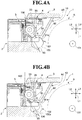
- the thermal printer 1 includes the first separation wall 80 as the separator described above. As illustrated in FIG. 4A to FIG. 4C , the first separation wall 80 is provided at a position at which, when the rolling start portion 102 of the recording sheet 100 is unrolled, at least a part of a peripheral surface of the rolling start portion 102 is brought into abutment against the first separation wall 80 along with a repulsive force generated by the stiffness of the recording sheet 100.
- the first separation wall 80 is provided to the recording-sheet receiving portion 10 and is located in the vicinity of the roll sheet R.
- the first separation wall 80 is formed as a substantially L-shaped member including a short wall 81 and a long wall 82.
- the short wall 81 is arranged in the vicinity of a path of the recording sheet 100 unrolled from the roll sheet R.
- the long wall 82 described above is mounted to an inner wall of the printer cover 3 so that the first separation wall 80 is supported.
- a surface 81a of the short wall 81 of the first separation wall 80 functions as a surface against which the rolling start portion 102 of the unrolled recording sheet 100 is brought into abutment. Further, in FIG. 4A to FIG. 4C , the surface 81a of the short wall 81 is a surface oriented in (facing) the front-and-back direction L1 of FIG. 4A to FIG. 4C .
- the roll sheet R which is obtained by rolling the recording sheet 100 into the roll shape around the core body 101 and is received in the recording-sheet receiving portion 10, is sequentially conveyed to a position between the platen unit 4 and the head unit 5 and subjected to thermal printing. After the thermal printing, the roll sheet R is cut by the movable blade 22 and the fixed blade 34 illustrated in FIG. 3 and is conveyed to the outside as, for example, a receipt.
- the recording sheet 100 of the roll sheet R is sequentially unrolled, and a portion of the rolling start portion 102 having the turn-back shape is finally separated from the core body 101.
- the rolling start portion 102 separated from the core body 101 is conveyed toward the gap portion S between the platen unit 4 and the head unit 5, and is brought into abutment against the surface 81a of the short wall 81 of the first separation wall 80. At this time, the rolling start portion 102 is brought into abutment against the surface 81a by the firmness (stiffness) given by the characteristic of the recording sheet 100 as paper.
- a material of the first separation wall 80 is not particularly limited.
- a material which is capable of securing a constant frictional force with respect to the recording sheet 100 can be suitably employed.
- Such a material is not particularly limited, and a material which is the same as a resin material forming the platen unit 4 and the head unit 5 of the thermal printer 1 can be used.
- an acrylonitrile butylene styrene (ABS) resin or a polycarbonate (PC) resin may be suitably used.
- the recording sheet 100 which is unrolled from the core body 101 and is curled is brought into abutment against the surface 81a of the first separation wall 80 by the stiffness of the recording sheet, and one part of the recording sheet 100 on the surface 81a side at the rolling start portion 102 stays due to the friction generated with the surface 81a, and only another part of the recording sheet 100 at the rolling start portion 102 is pulled in a sheet-passage direction.
- a relative action between parts of the recording sheet 100 folded on each other at the rolling start portion 102 causes the rolling start portion 102 to be conveyed to the gap portion S between the head unit 5 and the platen unit 4 while being opened, that is, while the parts of the recording sheet 100 are separated. Accordingly, passage of the rolling start portion 102 while keeping the turn-back shape can be prevented. That is, the recording sheet 100 is conveyed in a state without overlapping conveyance, which is a normal conveyance. Therefore, for example, a paper jam does not occur in the thermal printer 1, and the last part of the recording sheet 100 is allowed to pass even at a timing immediately before the roll sheet R (recording sheet 100) runs out. With this, a leading edge 100a of the recording sheet 100 passes in the vicinity of a sheet run-out sensor (not shown), and sheet run-out detection can be normally performed, thereby being capable of also preventing erroneous detection by the sheet run-out sensor.
- the turn-back shape at the rolling start portion 102 of the recording sheet 100 can be opened and eliminated. Accordingly, the paper jam that occurs inside and the erroneous detection by the sheet run-out sensor can be avoided without causing a significant increase in cost, thereby leading to improvement in performance of the thermal printer.
- the short wall 81 provided to the first separation wall 80 be provided so as to pressurize at least a part of the peripheral surface of the rolling start portion 102 of the recording sheet 100. That is, it is preferred that the surface 81a of the short wall 81 be located at a position on a conveyance path of the recording sheet 100 at which the surface 81a can pressurize the recording sheet 100 having a tendency to be curled as in the example illustrated in FIG. 4A to FIG. 4C (for example, position closer to a second separation wall 90 described later).
- the frictional force generated between the first separation wall 80 and the peripheral surface of the recording sheet 100 increases, thereby being capable of more effectively separating the parts of the recording sheet 100 folded on each other at the rolling start portion 102.
- the separator in this embodiment is not limited to the configuration described above.
- a configuration in which a frictional-resistance member 83 is provided to the first separation wall 80 at a position at which at least a part of the peripheral surface of the rolling start portion 102 of the recording sheet 100 is brought into abutment be employed.
- the frictional-resistance member 83 is provided at the position on the first separation wall 80 at which the rolling start portion 102 of the recording sheet 100 is brought into abutment, a frictional force generated between the frictional-resistance member 83 and the peripheral surface of the recording sheet 100 increases, thereby being capable of more effectively separating the parts of the recording sheet 100 folded on each other at the rolling start portion 102.
- a material of the frictional-resistance member 83 is also not particularly limited, and any material having a friction coefficient capable of achieving a high frictional force with respect to the recording sheet 100, for example, a polyurethane foam or various rubber materials can be used without limitation.
- a configuration in which a locking portion 81b configured to lock the leading edge 100a formed into the turn-back shape at the rolling start portion 102 is provided to the first separation wall 80 at a position at which at least a part of the peripheral surface of the rolling start portion 102 of the recording sheet 100 is brought into abutment as in the example illustrated in FIG. 6A and FIG. 6B be employed.
- the locking portion 81b having a recess shape is provided at a distal end of the short wall 81 of the first separation wall 80.
- the frictional-resistance member 83 may also be provided in this case if desired.
- the locking portion 81b is provided at the position on the first separation wall 80 at which the rolling start portion 102 of the recording sheet 100 is brought into abutment, the leading edge 100a formed into the turn-back shape at the rolling start portion 102 is locked to the locking portion 81b, thereby being capable of more effectively separating the parts of the recording sheet 100 folded on each other at the rolling start portion 102.
- the rolling start portion 102 is brought into a floating state, thereby being capable of effectively separating the parts of the recording sheet 100 folded on each other.
- the locking portion 81b having a recess shape is provided to the short wall 81.
- the present invention is not limited to this configuration. For example, the effect described above can be obtained also when a locking portion having a protrusion shape is provided.
- the thermal printer 1 of this embodiment with the configuration including the first separation wall 80, the effect of separating the parts of the recording sheet 100 folded on each other at the rolling start portion 102 as described above can be obtained.
- the second separation wall 90 illustrated in FIG. 4A to FIG. 4C , FIG. 5 , and FIG. 6A be further provided.
- the second separation wall 90 is provided in the recording-sheet receiving portion 10 at the position of being opposed to the first separation wall 80 across the unrolled recording sheet 100 and at which at least a part of the peripheral surface of the rolling start portion 102 is brought into abutment along with the repulsive force generated by the stiffness of the recording sheet 100.
- the recording sheet 100 which is unrolled from the core body 101 and is curled is brought into abutment against the above-mentioned first separation wall 80 by the stiffness of the recording sheet 100 and is brought into abutment also against the second separation wall 90.
- the effect of reliably separating the parts of the recording sheet 100 folded on each other at the rolling start portion 102 can be obtained (see also the example illustrated in FIG. 7 ).
- a large diameter of the core body causes a diameter of the curling of the rolling start portion 102 to become larger. Therefore, even when it is difficult to bring the peripheral surface of the rolling start portion 102 into abutment against the first separation wall 80, the rolling start portion 102 is brought into abutment against the second separation wall 90, thereby being adaptable to roll sheets having various core diameters.
- the parts of the recording sheet 100 folded on each other at the rolling start portion 102 can be effectively separated while improving the ease of assembly and maintenance at the time of manufacture of the thermal printer 1.
- thermal printer 1A according to a second embodiment of the present invention is described mainly with reference to FIG. 8A, FIG. 8B , FIG. 9A, and FIG. 9B as appropriate.
- components which are in common with the thermal printer 1 according to the first embodiment mentioned above are denoted by the same reference symbols in the drawings, and detailed description thereof is omitted in some cases.
- the modifications to the first embodiment can also be made to the second and other embodiments.
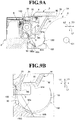
- FIG. 8A is a view for illustrating the thermal printer 1A according to the second embodiment, and is a partial cutaway view for illustrating a relationship of the first separation wall 80 and the second separation wall 90 provided to the recording-sheet receiving portion 10 with respect to the rolling start portion 102 formed into the turn-back shape when the rolling start portion 102 of the recording sheet 100 is significantly curled.
- FIG. 8B is an enlarged view for illustrating a main part of FIG. 8A .
- the thermal printer 1A according to the second embodiment illustrated in FIG. 8A and FIG. 8B further includes a guide portion in addition to the first separation wall 80 and the second separation wall 90 provided to the thermal printer 1 illustrated in FIG. 7 .
- the guide portion is located at a position of being opposed to the second separation wall 90 across the unrolled recording sheet 100 and in the vicinity of an inlet of the gap portion S to which the recording sheet 100 is conveyed, and is configured to guide the recording sheet 100.
- the thermal printer 1A employs a configuration in which the guide portion is formed of a guide shaft 95 which is in parallel with the core body (that is, shaft portion) 101 (see, for example, FIG. 4A ) of the recording sheet 100 and is pivotable.
- the guide portion formed of the guide shaft 95 configured to guide the recording sheet 100 is provided to the platen unit 4, and hence, as illustrated in FIG. 8A and FIG. 8B , the rolling start portion 102 of the recording sheet 100 is reliably brought into abutment against the second separation wall 90. That is, even when the recording sheet 100 which is unrolled from the core body 101 and is significantly curled is not brought into abutment against the first separation wall 80, the recording sheet 100 is brought into abutment against the second separation wall 90 by a guiding action of the guide shaft 95.
- the recording sheet 100 is caused to stay by the friction generated with a surface 90a of the second separation wall 90, and only another part of the recording sheet 100 at the rolling start portion 102 is pulled in the sheet-passage direction. Then, as in the case of the first embodiment, the rolling start portion 102 is opened by a relative action between parts of the recording sheet 100 folded on each other at the rolling start portion 102, and the recording sheet 100 is conveyed to the gap portion S between the head unit 5 and the platen unit 4 while the parts of the recording sheet 100 are separated, thereby being capable of preventing passage of the rolling start portion 102 keeping the turn-back shape. Accordingly, as in the case described above, the recording sheet 100 is conveyed in a state without overlapping conveyance.
- a locking portion 90b having a recess shape configured to lock the leading edge 100a of the rolling start portion 102 formed into the turn-back shape be provided.
- a locking portion 90b may also be provided in the first and other embodiments.
- the locking portion provided to the second separation wall 90 is not limited to the one having the recess shape as in the illustrated example, and a locking portion having a protrusion shape can also be provided.
- a frictional-resistance member is provided at the position on the surface 90a of the second separation wall 90 at which at least a part of the peripheral surface of the rolling start portion 102 of the recording sheet 100 is brought into abutment.
- a frictional force generated between the frictional-resistance member (not shown) and the peripheral surface of the recording sheet 100 increases, thereby being capable of more effectively separating the parts of the recording sheet 100 folded on each other at the rolling start portion 102.
- a frictional-resistance member may also be provided to the surface 90a of the second separation wall 90 in the first and other embodiments, where the second separation wall is provided.
- the guide shaft 95 there may be used a guide shaft obtained by, for example, assembling a roller made of a rubber material or a resin material (for example, ABS resin or PC resin) to a core shaft made of, for example, a stainless steel material.
- a guide shaft obtained by, for example, assembling a roller made of a rubber material or a resin material (for example, ABS resin or PC resin) to a core shaft made of, for example, a stainless steel material.
- the frictional-resistance member (not shown) is provided to the surface 90a of the second separation wall 90, there may be used the frictional-resistance member made of the same material as the frictional-resistance member 83 provided to the thermal printer 1 according to the above-mentioned first embodiment.
- the guide portion described in this embodiment is not limited to the guide portion formed of the pivotable guide shaft 95 exemplified in FIG. 8A and FIG. 8B .
- the guide portion may be formed of a guide wall 96, which is provided in the vicinity of the platen roller 33 of the platen unit 4 and projects from the platen frame 35 so as to be opposed to the second separation wall 90.
- FIG. 9A and FIG. 9B the guide portion may be formed of a guide wall 96, which is provided in the vicinity of the platen roller 33 of the platen unit 4 and projects from the platen frame 35 so as to be opposed to the second separation wall 90.
- FIG. 9A is a partial cutaway view for illustrating a relationship of the first separation wall 80 and the second separation wall 90 provided to the recording-sheet receiving portion 10 with respect to the rolling start portion 102 formed into the turn-back shape in a case in which the guide portion is formed of the guide wall 96 and in which the rolling start portion 102 of the recording sheet 100 is significantly curled.
- FIG. 9B is an enlarged view for illustrating a main part of FIG. 9A .
- the recording sheet 100 can be reliably guided to be brought into abutment against the second separation wall 90, thereby being capable of reliably separating the parts of the recording sheet 100 folded on each other at the rolling start portion 102.
- the guide portion formed of the guide wall 96 the guide portion can be formed integrally with the resin member forming the platen unit 4, thereby being capable of improving the productivity of the thermal printer 1A and reducing the manufacturing cost.
- thermal printer 1B according to a third embodiment of the present invention is described mainly with reference to FIG. 10A, FIG. 10B , and FIG. 10C as appropriate.
- components which are in common with the thermal printer 1 and 1A according to the first and the second embodiments mentioned above are denoted by the same reference symbols in the drawings, and detailed description thereof is omitted in some cases.
- FIG. 10A is a view for illustrating the thermal printer 1B according to the third embodiment, and is a partial cutaway view for illustrating a relationship of the first separation wall 80 and a tension bar 84 provided to the recording-sheet receiving portion 10 with respect to the rolling start portion 102 of the recording sheet 100 formed into the turn-back shape.
- the recording sheet 100 is guided by the tension bar 84 so that the rolling start portion 102 of the recording sheet 100 is reliably brought into abutment in a pressurized state against the first separation wall 80. That is, the recording sheet 100 which is unrolled from the core body 101 (see, for example, FIG. 4A ) and is curled is brought into abutment against the first separation wall 80 by a guiding action of the tension bar 84. The recording sheet 100 is caused to stay by the friction generated with the surface 81a of the first separation wall 80, and only another part of the recording sheet 100 at the rolling start portion 102 is pulled in the sheet-passage direction.
- the rolling start portion 102 is opened by a relative action between parts of the recording sheet 100 folded on each other at the rolling start portion 102, and the recording sheet 100 is conveyed to the gap portion S between the head unit 5 and the platen unit 4 while the parts of the recording sheet 100 are separated, thereby being capable of preventing passage of the rolling start portion 102 keeping the turn-back shape. Accordingly, as in the case described above, the recording sheet 100 is conveyed in a state without overlapping conveyance. Therefore, a paper jam or the like does not occur in the thermal printer 1B, and the last part of the recording sheet 100 is allowed to pass even at a timing immediately before the roll sheet R (see, for example, FIG. 4A ) runs out. Further, erroneous detection by the sheet run-out sensor can also be prevented.
- a material used for the tension bar 84 is not particularly limited, and a material which is the same as a resin material used for each member forming the platen unit 4 can be used.
- the material include an ABS resin and a PC resin, and the tension bar 84 can be obtained by, for example, injection molding using those resin materials.
- the tension bar 84 can be formed of, for example, a coil spring (not shown) so as to be pressurized and urged against the recording sheet 100.
- the tension bar provided to the thermal printer 1B is not limited to the configuration described above, and there may be employed, for example, a tension bar 84A as illustrated in FIG. 10B and FIG. 10C .
- the tension bar 84A has a configuration in which a locking portion 84b configured to lock the leading edge 100a of the recording sheet 100 formed into the turn-back shape at the rolling start portion 102 is provided at a part of the surface 84a.
- FIG. 10B is a partial cutaway view for illustrating a relationship of the first separation wall 80 and the tension bar 84A provided to the recording-sheet receiving portion 10 with respect to the rolling start portion 102 of the recording sheet 100 formed into the turn-back shape when the tension bar 84A to which the locking portion 84b is provided is employed.
- FIG. 10C is a partial enlarged view for illustrating a main part of FIG. 10B .
- the locking portion 84b is formed on the surface 84a of the tension bar 84A at a position at which the leading edge 100a forming the rolling start portion 102 of the recording sheet 100 is brought into abutment.
- the tension bar 84A having the configuration in which the locking portion 84b is provided as illustrated in FIG. 10B and FIG. 10C , when the recording sheet 100 is guided to the first separation wall 80 by the tension bar 84A, the leading edge 100a formed into the turn-back shape at the rolling start portion 102 is locked to the locking portion 84b. Accordingly, the parts of the recording sheet 100 folded on each other at the rolling start portion 102 can be more effectively separated.
- the locking portion 84b is provided to the surface 84a of the tension bar 84A with reference to FIG. 10B and FIG. 10C .
- this embodiment is not limited to such a configuration.
- a locking portion having a protrusion shape (not shown) or a friction-resistance member is provided in place of the locking portion 84b of the tension bar 84A at the same position is employed, similarly to the example described above, the parts of the recording sheet 100 folded on each other at the rolling start portion 102 can be more effectively separated.
- the locking portion 84b may also be provided in other embodiments where a tension bar 84 is provided.
- thermal printer 1C according to a fourth embodiment of the present invention is described mainly with reference to FIG. 11A and FIG. 11B as appropriate.
- components which are in common with the thermal printer 1, 1A, and 1B according to the first to third embodiments mentioned above are denoted by the same reference symbols in the drawings, and detailed description thereof is omitted in some cases.
- FIG. 11A is a view for illustrating the thermal printer 1C according to the fourth embodiment, and is a partial cutaway view for illustrating a relationship of a third separation wall 92, the tension bar 84, and a guide wall 94 provided to the recording-sheet receiving portion 10 with respect to the rolling start portion 102 of the recording sheet 100 formed into the turn-back shape.
- FIG. 11B is a partial enlarged view for illustrating a main part of FIG. 11A .
- the thermal printer 1C according to the fourth embodiment illustrated in FIG. 11A and FIG. 11B is different from the thermal printer 1B according to the third embodiment illustrated in, for example, FIG. 10A in that the first separation wall 80 is not provided. Meanwhile, the thermal printer 1C according to this embodiment includes the tension bar 84 configured to guide the recording sheet 100 toward the platen unit 4 side at a position of being opposed to the platen unit 4 across the unrolled recording sheet 100. Further, the thermal printer 1C includes the guide wall (guide portion) 94.
- the guide wall 94 is provided so as to be opposed to the tension bar 84 at a position in the vicinity of the inlet of the gap portion S to which the recording sheet 100 is conveyed in the platen unit 4, and the recording sheet 100 guided by the tension bar 84 toward the platen unit 4 side is brought into abutment against the guide wall 94.
- This guide wall 94 is formed such that a part of the platen frame 35 provided to the platen unit 4 projects.
- the thermal printer 1C includes the third separation wall 92.
- the third separation wall 92 is provided on a side opposite to the guide wall 94 across the gap portion S in the vicinity of the inlet of the gap portion S, and at least a part of the recording sheet 100 guided by the tension bar 84 and the guide wall 94 is brought into abutment against the third separation wall 92.
- a distal end 84c of the tension bar 84 and a distal end of the guide wall 94 are arranged so as to overlap each other in a direction in which the platen unit 4 and the tension bar 84 are opposed to each other. That is, in the example illustrated in FIG. 11A and FIG. 11B , the distal end of the guide wall 94 provided to the platen unit 4 is arranged so as to project downward in the direction L1 of FIG. 11A and FIG. 11B (that is, downward in the vertical direction of FIG. 11A and FIG. 11B ) as compared to the distal end 84c of the tension bar 84.
- the sheet-passage path of the recording sheet 100 is sharply changed toward the tension bar 84 side by the guide wall 94 provided such that a part of the platen frame 35 provided to the platen unit 4 projects. Further, the tension bar 84, the guide wall 94, and the third separation wall 92 are arranged such that an angle K of the recording sheet 100 with respect to the surface 92a of the third separation wall 92 becomes less than 90° when the leading edge 100a of the rolling start portion 102 of the recording sheet 100 is brought into abutment against the third separation wall 92.
- the thermal printer 1C of this embodiment with the tension bar 84, the guide wall 94, and the third separation wall 92 described above, as illustrated in FIG. 11A and FIG. 11B , first, the recording sheet 100 is guided by the tension bar 84 so that the rolling start portion 102 of the recording sheet 100 is brought into abutment in a pressurized state against the guide wall 94. At this time, as the distal end 84c of the tension bar 84 and the distal end of the guide wall 94 pressurize the recording sheet 100 from both surface sides, the recording sheet 100 is formed into a shape of sharply turning at the distal end of the guide wall 94, and hence the turn-back shape of the rolling start portion 102 is opened.
- the leading edge 100a of the recording sheet 100 at the rolling start portion 102 is brought into abutment against the third separation wall 92 so that the recording sheet 100 is conveyed to the gap portion S between the head unit 5 and the platen unit 4 while the parts of the recording sheet 100 are separated, thereby being capable of preventing passage of the rolling start portion 102 keeping the turn-back shape. Accordingly, as in the case described above, the recording sheet 100 is conveyed in a state without overlapping conveyance. Therefore, a paper jam or the like does not occur in the thermal printer 1C, and the last part of the recording sheet 100 is allowed to pass even at a timing immediately before the roll sheet R (see, for example, FIG. 4A ) runs out. Further, erroneous detection by the sheet run-out sensor can also be prevented.
- a gap between the tension bar 84 and the guide wall 94 be regulated to be as narrow as possible. Further, in the viewpoint of allowing the turn-back shape of the rolling start portion 102 to be easily opened, it is preferred that, as described above, the tension bar 84, the guide wall 94, and the third separation wall 92 be arranged such that the angle K of the recording sheet 100 with respect to the surface 92a of the third separation wall 92 becomes less than 90° when the leading edge 100a of the recording sheet 100 is brought into abutment against the third separation wall 92.
- tension bar 84 used in this embodiment a tension bar made of the material described in the third embodiment can be employed.
- configuration for pressurizing and urging the recording sheet 100 there can be employed the configuration of using the coil spring (not shown) or the like described in the third embodiment.
- a configuration in which a locking portion 92b configured to lock the leading edge 100a formed into the turn-back shape is provided at the position on the surface 92a of the third separation wall 92 at which at least a part of the peripheral surface of the rolling start portion 102 of the recording sheet 100 is brought into abutment be employed.
- the locking portion 92b provided to the third separation wall 92 As described above, with the locking portion 92b provided to the third separation wall 92, the leading edge 100a formed into the turn-back shape at the rolling start portion 102 is locked to the locking portion 92b, thereby being capable of more effectively separating parts of the recording sheet 100 folded on each other. Further, with the locking portion 92b provided to the third separation wall 92, the action of effectively separating the parts of the recording sheet 100 folded on each other can be obtained regardless of the angle at which the leading edge 100a of the recording sheet 100 is brought into abutment against the surface 92a of the third separation wall 92.
- the locking portion 92b having a recess shape is provided to the third separation wall 92, but the present invention is not limited to such a configuration. For example, the effect described above can be obtained even in a case in which the locking portion having a protrusion shape is provided.
- a locking portion 92b having a recess shape may also be provided to the third separation wall 92 in other
- thermal printer 1D according to a fifth embodiment of the present invention is described mainly with reference to FIG. 13 as appropriate.
- components which are in common with the thermal printer 1, 1A, 1B, and 1C according to the first to fourth embodiments mentioned above are denoted by the same reference symbols in the drawings, and detailed description thereof is omitted in some cases.
- FIG. 13 is a view for illustrating the thermal printer 1D according to the fifth embodiment, and is a partial cutaway view for illustrating a relationship of the third separation wall 92, the tension bar 84, and a lower end 99 of the platen unit 4 provided to the recording-sheet receiving portion 10 with respect to the rolling start portion 102 of the recording sheet 100 formed into the turn-back shape.
- the thermal printer 1D according to this embodiment includes the tension bar 84, a fourth separation wall 93, and the third separation wall 92.
- the tension bar 84 is configured to guide the recording sheet 100 toward the platen unit 4 side at a position of being opposed to the platen unit 4 across the recording sheet 100.
- the fourth separation wall 93 is arranged between the platen unit 4 and the tension bar 84, and is configured to guide the recording sheet 100 between the fourth separation wall 93 and the tension bar 84.
- the third separation wall 92 is provided in the vicinity of the inlet of the gap portion S, and at least a part of the recording sheet 100 guided by the tension bar 84 and the fourth separation wall 93 is brought into abutment with the third separation wall 92.
- the thermal printer 1D according to this embodiment illustrated in FIG. 13 is different from the thermal printer 1C according to the fourth embodiment illustrated in FIG. 11A and FIG. 11B in that the fourth separation wall 93 described above is further provided. Further, the thermal printer 1D according to this embodiment is different from the thermal printer 1C according to the fourth embodiment also in that the guide wall which significantly projects is not provided to the platen frame 35 of the platen unit 4.
- the fourth separation wall 93 is provided to the recording-sheet receiving portion 10 and located in the vicinity of the roll sheet R, and is a member having a substantially plate shape arranged between the platen unit 4 and the tension bar 84 as described above.
- the fourth separation wall 93 has one end 93a side arranged between the platen unit 4 and the tension bar 84.
- one surface 93c of the fourth separation wall 93 on the one end 93a side is formed as a recess-shaped region 93e that gently recesses in conformity with a round outer shape of the lower end 99 of the platen frame 35.
- another surface 93d of the fourth separation wall 93 on a side opposite to the one surface 93c described above functions as a surface against which the rolling start portion 102 of the unrolled recording sheet 100 is brought into abutment.
- the fourth separation wall 93 is arranged such that the one end 93a overlaps the distal end 84c of the tension bar 84 in the direction in which the platen unit 4 (platen frame 35) and the tension bar 84 are opposed to each other. Further, another end 93b side is mounted to an inner wall of the printer cover 3 so that the fourth separation wall 93 in the illustrated example is supported.
- the thermal printer 1D of this embodiment with the tension bar 84, the fourth separation wall 93, and the third separation wall 92 described above, as illustrated in FIG. 13 , first, the recording sheet 100 is guided by the tension bar 84, and the rolling start portion 102 of the recording sheet 100 is brought into abutment against the lower end 99 of the platen frame 35. At this time, unlike the case of the thermal printer 1C according to the fourth embodiment, the sheet-passage path of the recording sheet 100 is formed into a relatively gently curved shape.
- the turn-back shape of the rolling start portion 102 of the recording sheet 100 allowed to pass between the tension bar 84 and the fourth separation wall 93 is opened.
- the leading edge 100a of the recording sheet 100 at the rolling start portion 102 is brought into abutment against the third separation wall 92 so that the recording sheet 100 is conveyed to the gap portion S between the head unit 5 and the platen unit 4 while the parts of the recording sheet 100 are separated, thereby being capable of preventing passage of the rolling start portion 102 keeping the turn-back shape. Accordingly, as in the case described above, the recording sheet 100 is conveyed in a state without overlapping conveyance.
- a material of the fourth separation wall 93 is not particularly limited, and there may be used, for example, similarly to the first separation wall 80 provided to the thermal printer 1 according to the first embodiment, a material which is the same as the resin material forming the platen unit 4 and the head unit 5, such as an ABS resin or a PC resin.
- the parts of the recording sheet 100 folded on each other at the rolling start portion 102 can be effectively separated while improving the ease of assembly and maintenance at the time of manufacture of the thermal printer 1D.
- thermal printer 1E according to a sixth embodiment of the present invention is described mainly with reference to FIG. 14A and FIG. 14B as appropriate.
- components which are in common with the thermal printer 1, 1A, 1B, 1C, and 1D according to the first to fifth embodiments mentioned above are denoted by the same reference symbols in the drawings, and detailed description thereof is omitted in some cases.
- FIG. 14A is a view for illustrating the thermal printer 1E according to the sixth embodiment, and is a cutaway view for illustrating a relationship of the third separation wall 92, the guide wall 94, and a guide roller 85 provided to the recording-sheet receiving portion 10 with respect to the rolling start portion 102 of the recording sheet 100 formed into the turn-back shape.
- FIG. 14B is an enlarged view for illustrating a main part of FIG. 14A .
- the thermal printer 1E according to this embodiment includes the third separation wall 92, the guide wall 94, and the guide roller 85.
- the third separation wall 92 is provided on a side opposite to the guide wall 94 across the gap portion S in the vicinity of the inlet of the gap portion S, and at least a part of the recording sheet 100 is brought into abutment against the third separation wall 92.
- the guide wall 94 is provided at a position in the vicinity of the inlet of the gap portion S to which the recording sheet 100 is conveyed in the platen unit 4.
- the guide roller 85 is provided in the vicinity of the guide wall 94, and is configured to guide the recording sheet 100 between the guide roller 85 and the guide wall 94.
- the guide wall 94 which is provided such that a part of the platen frame 35 provided to the platen unit 4 projects, and the guide roller 85 are arranged in such a relationship that the sheet-passage path of the recording sheet 100 is sharply changed. Further, the guide roller 85, the guide wall 94, and the third separation wall 92 are arranged such that the angle K of the recording sheet 100 with respect to the surface 92a of the third separation wall 92 becomes less than 90° when the leading edge 100a of the rolling start portion 102 of the recording sheet 100 is brought into abutment against the third separation wall 92.
- the recording sheet 100 is guided by the guide roller 85 so that the rolling start portion 102 of the recording sheet 100 is brought into abutment in a pressurized state against the guide wall 94.
- the guide roller 85 and the distal end of the guide wall 94 pressurize the recording sheet 100 from both surface sides, the recording sheet 100 is formed into a shape of sharply turning at the distal end of the guide wall 94, and hence the turn-back shape of the rolling start portion 102 is opened.
- the leading edge 100a of the recording sheet 100 at the rolling start portion 102 is brought into abutment against the third separation wall 92 so that the recording sheet 100 is conveyed to the gap portion S between the head unit 5 and the platen unit 4 while the parts of the recording sheet 100 are separated, thereby being capable of preventing passage of the rolling start portion 102 keeping the turn-back shape. Accordingly, as in the case described above, the recording sheet 100 is conveyed in a state without overlapping conveyance. Therefore, a paper jam or the like does not occur in the thermal printer 1E, and the last part of the recording sheet 100 is allowed to pass even at a timing immediately before the roll sheet R (see, for example, FIG. 4A ) runs out. Further, erroneous detection by the sheet run-out sensor can also be prevented.
- a gap between the guide roller 85 and the guide wall 94 be regulated to be as narrow as possible.
- the guide roller 85, the guide wall 94, and the third separation wall 92 be arranged such that the angle K of the recording sheet 100 with respect to the surface 92a of the third separation wall 92 becomes less than 90° when the leading edge 100a of the recording sheet 100 is brought into abutment against the third separation wall 92.
- a guide roller 85 used in this embodiment similarly to the guide shaft 95 in the thermal printer 1A according to the second embodiment mentioned above, there may be used a guide roller obtained by, for example, assembling a roller made of a rubber material or a resin material, such as an ABS resin or a PC resin, to a core shaft made of, for example, a stainless steel material.
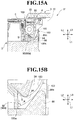
- thermal printer 1F according to a seventh embodiment of the present invention is described mainly with reference to FIG. 15A and FIG. 15B as appropriate.
- components which are in common with the thermal printer 1, 1A, 1B, 1C, 1D, and 1E according to the first to sixth embodiments mentioned above are denoted by the same reference symbols in the drawings, and detailed description thereof is omitted in some cases.
- FIG. 15A is a view for illustrating the thermal printer 1F according to the seventh embodiment, and is a partial cutaway view for illustrating a relationship of the third separation wall 92, the guide wall 94, and a regulation wall 86 provided to the recording-sheet receiving portion 10 with respect to the rolling start portion 102 of the recording sheet 100 formed into the turn-back shape.
- FIG. 15B is an enlarged view for illustrating a main part of FIG. 15A .
- the thermal printer 1F according to this embodiment includes the third separation wall 92, the guide wall 94, and the regulation wall 86.
- the third separation wall 92 is provided on a side opposite to the guide wall 94 across the gap portion S in the vicinity of the inlet of the gap portion S, and at least a part of the recording sheet 100 is brought into abutment against the third separation wall 92.
- the guide wall 94 is provided at a position in the vicinity of the inlet of the gap portion S to which the recording sheet 100 is conveyed in the platen unit 4.
- the regulation wall 86 is provided so as to be opposed to the guide wall 94 across the recording sheet 100.
- a distal end 86a of the regulation wall 86 and the distal end of the guide wall 94 are arranged so as to overlap each other in a direction in which the platen unit 4 and the regulation wall 86 are opposed to each other. That is, in the example illustrated in FIG. 15A and FIG. 15B , the distal end of the guide wall 94 provided to the platen unit 4 is arranged so as to project downward in the direction L1 of FIG. 15A and FIG. 15B (that is, downward in the vertical direction of FIG. 15A and FIG. 15B ) as compared to the distal end 86a of the regulation wall 86.
- the guide wall 94 which is provided such that a part of the platen frame 35 provided to the platen unit 4 projects, and the regulation wall 86 are arranged in such a relationship that the sheet-passage path of the recording sheet 100 is sharply changed.
- the regulation wall 86, the guide wall 94, and the third separation wall 92 are arranged such that the angle K of the recording sheet 100 with respect to the surface 92a of the third separation wall 92 becomes less than 90° when the leading edge 100a of the rolling start portion 102 of the recording sheet 100 is brought into abutment against the third separation wall 92.
- the recording sheet 100 is guided by the distal end 86a of the regulation wall 86 so that the rolling start portion 102 of the recording sheet 100 is brought into abutment in a pressurized state against the guide wall 94.
- the distal end 86a of the regulation wall 86 and the distal end of the guide wall 94 pressurize the recording sheet 100 from both surface sides, the recording sheet 100 is formed into a shape of sharply turning at the distal end of the guide wall 94, and hence the turn-back shape of the rolling start portion 102 is opened.
- the leading edge 100a of the recording sheet 100 at the rolling start portion 102 is brought into abutment against the third separation wall 92 so that the recording sheet 100 is conveyed to the gap portion S between the head unit 5 and the platen unit 4 while the parts of the recording sheet 100 are separated, thereby being capable of preventing passage of the rolling start portion 102 keeping the turn-back shape. Accordingly, as in the case described above, the recording sheet 100 is conveyed in a state without overlapping conveyance. Therefore, a paper jam or the like does not occur in the thermal printer 1F, and the last part of the recording sheet 100 is allowed to pass even at a timing immediately before the roll sheet R (see, for example, FIG. 4A ) runs out. Further, erroneous detection by the sheet run-out sensor can also be prevented.
- a gap between the distal end 86a of the regulation wall 86 and the guide wall 94 also be regulated to be as narrow as possible.
- the regulation wall 86, the guide wall 94, and the third separation wall 92 be arranged such that the angle K of the recording sheet 100 with respect to the surface 92a of the third separation wall 92 becomes less than 90° when the leading edge 100a of the recording sheet 100 is brought into abutment against the third separation wall 92.
- thermal printer 1G according to an eighth embodiment of the present invention is described mainly with reference to FIG. 16A, FIG. 16B , and FIG. 16C as appropriate.
- components which are in common with the thermal printer 1, 1A, 1B, 1C, 1D, 1E, and 1F according to the first to seventh embodiments mentioned above are denoted by the same reference symbols in the drawings, and detailed description thereof is omitted in some cases.
- FIG. 16A, FIG. 16B , and FIG. 16C are views for illustrating the thermal printer 1G according to the eighth embodiment, and are partial cutaway views for illustrating a relationship of a pair of guide rolls 97A and 97B with respect to the rolling start portion 102 of the recording sheet 100 formed into the turn-back shape.
- the thermal printer 1G according to this embodiment employs a configuration in which the separator is formed of the pair of guide rolls 97A and 97B.
- the pair of guide rolls 97A and 97B are provided such that, when the rolling start portion 102 of the recording sheet 100 is unrolled, the pair of guide rolls 97A and 97B pressurize the recording sheet 100 so as to allow at least a part of the recording sheet 100 to be brought into abutment against a frictional-resistance member 98.
- the guide roll 97A and the guide roll 97B are provided in the vicinity of the platen roller 33 in the platen unit 4 and are sequentially arranged from an upstream side of the recording sheet 100.
- the frictional-resistance member 98 is provided at a position more apart from the platen roller 33 than a line connecting the pair of guide rolls 97A and 97B.
- the guide roll 97A provided on the upstream side and the guide roll 97B on a downstream side are arranged so as to be located apart in the vertical direction of FIG. 16A, FIG. 16B , and FIG.
- the pair of guide rolls 97A and 97B are capable of pressurizing the recording sheet 100 such that at least a part of the recording sheet 100 is brought into abutment against the frictional-resistance member 98.
- the thermal printer 1G of this embodiment first, the recording sheet 100 unrolled from the roll sheet R (see, for example, FIG. 4A ) is sequentially conveyed to the gap portion S between the head unit 5 and the platen unit 4 via the pair of guide rolls 97A and 97B. After thermal printing, the recording sheet 100 is cut as appropriate and conveyed to the outside. Then, when the remaining amount of the roll sheet R (recording sheet 100) becomes small, and the rolling start portion 102 rolled around the core body 101 (see, for example, FIG. 4A ) is unrolled as illustrated in FIG.
- the recording sheet 100 which is unrolled from the core body 101 and is curled is brought into abutment in a pressurized state against the frictional-resistance member 98 by the stiffness of the recording sheet 100 and a guiding action of the guide roll 97B provided on the downstream side.
- the recording sheet 100 on the frictional-resistance member 98 side at the rolling start portion 102 is caused to stay by the friction generated with the frictional-resistance member 98, and only another part of the recording sheet 100 at the rolling start portion 102 is pulled in the sheet-passage direction.
- the rolling start portion 102 is opened by a relative action between parts of the recording sheet 100 folded on each other at the rolling start portion 102, and is conveyed to the gap portion S between the head unit 5 and the platen unit 4 while the parts of the recording sheet 100 are separated. That is, the recording sheet 100 is conveyed in a state without overlapping conveyance keeping the turn-back shape of the rolling start portion 102. Therefore, a paper jam or the like does not occur in the thermal printer 1G, and the last part of the recording sheet 100 is allowed to pass even at a timing immediately before the roll sheet R (recording sheet 100) runs out. Further, erroneous detection by the sheet run-out sensor can also be prevented.
- a guide roller obtained by, for example, assembling a roller made of a rubber material or a resin material, such as an ABS resin or a PC resin, to a core shaft made of, for example, a stainless steel material.
- the frictional-resistance member 98 is also not particularly limited, and similarly to the frictional-resistance member 83 provided in the thermal printer 1 according to the first embodiment mentioned above, any material having a friction coefficient capable of achieving a high frictional force with respect to the recording sheet 100, for example, a polyurethane foam or various rubber materials can be suitably employed.
- the thermal printers 1, 1A, 1B, 1C, 1D, 1E, 1F, and 1G of the first to eighth embodiments with the respective configurations described above, the parts of the recording sheet 100 folded on each other at the rolling start portion 102 which is rolled around the core body 101 and has the turn-back shape in the recording sheet 100 rolled into the roll shape around the core body 101 are effectively separated. Accordingly, conveyance of the rolling start portion 102 to the gap portion S between the head unit 5 and the platen unit 4 while keeping the turn-back shape can be prevented. Therefore, at the timing of the sheet run-out of the recording sheet 100 having the roll shape, the paper jam or the like does not occur inside the printer, and erroneous detection by the sensor can also be prevented. Thus, a thermal printer which is conspicuously excellent in reliability can be provided.
Landscapes
- Handling Of Sheets (AREA)
- Electronic Switches (AREA)
- Handling Of Continuous Sheets Of Paper (AREA)
Abstract
Description
- The present invention relates to a thermal printer.
- For a printer configured to print predetermined information on a recording sheet as represented by, for example, a thermal printer, a recording sheet obtained by rolling heat-sensitive paper into a roll shape around a core body is used (see, for example, Patent Literature 1).
- In a related-art thermal printer, when the thermal printer is driven under a state in which the recording sheet is absent, there is a risk of causing a defect such as thermal destruction of a heat-generating element (thermal head). In order to prevent such driving without the recording sheet, typically, a recording-sheet sensor configured to detect presence or absence of the recording sheet is provided at a position on an upstream side of the heat-generating element. Further, at the position of the recording-sheet sensor on a path of the recording sheet, in order to more reliably detect the presence or absence of the recording sheet, a gap is regulated to be narrow in a thickness direction of the recording sheet.
- Here, for the reason of manufacturing, as illustrated in
FIG. 17A , it is sometimes required that the recording sheet rolled into the roll shape be formed such that a leadingedge 100a of arecording sheet 100 is formed into a turn-back shape of turning back in a direction opposite to a rolling direction at arolling start portion 102 of therecording sheet 100, which is a portion of starting rolling around a shaft portion (core; core body) - in other words, where the leading edge of the recording sheet starts to be rolled around the shaft portion. As such, therolling start portion 102 is inside the roll near the shaft and is printed on when the roll has run out or is near running out. When the roll runs out, the leading edge that is rolled around the shaft portion may be considered to become the trailing edge. However, for convenience it will be referred to as the leading edge in this specification. However, as illustrated inFIG. 17B and FIG. 17C , in the case in which therolling start portion 102 of therecording sheet 100 is formed into the turn-back shape, when therolling start portion 102 is conveyed into the narrow gap while keeping the turn-back shape, a paper jam may occur to cause, for example, step out of a driving motor or tooth skipping of a gear. As a result, there is a fear in that a driving force is not transmitted to therecording sheet 100, and sheet feeding cannot be performed. In such a case, therecording sheet 100 stays around the sensor on the path of therecording sheet 100. Accordingly, a detection signal of the sensor remains in a state of indicating the presence of the recording sheet, and printing processing with use of the heat-generating element is continued. Meanwhile, the sheet feeding cannot be performed, and hence a receipt or the like cannot be issued. In particular, occurrence of the circumstance described above in an automatic teller machine (ATM) or an unmanned terminal provided in a kiosk may cause serious problems in terms of both business and trust. Further, when such a state continues for a long period of time, the printing processing with the use of the heat-generating element is performed at the same position on therecording sheet 100. As a result, heat stays in the heat-generating element, which may cause defects such as thermal destruction of the heat-generating element and poor printing due to an increase in resistance value. - In view of the problems described above, there has been a demand for a reliable thermal printer, which is capable of reliably separating parts of the recording sheet folded on each other and preventing a paper jam or the like even in a case in which the rolling start portion of the recording sheet rolled into the roll shape has the turn-back shape.
- According to one embodiment of the present invention, there is provided a thermal printer, including: a head unit including a thermal head configured to perform printing on a recording sheet; a platen unit, which includes a platen roller configured to convey the recording sheet, and is separably combined with the head unit; a printer main body, which has a recording-sheet receiving portion configured to receive the recording sheet, and has the head unit mounted thereto; a printer cover, which has the platen unit mounted thereto, and is coupled to the printer main body so as to be pivotable; and a separator, which is provided in the recording-sheet receiving portion, and is configured to separate parts of the recording sheet, which is rolled into a roll shape around a core body, folded on each other at a rolling start portion, which is rolled around the core body and has a turn-back shape.
- In the above-mentioned thermal printer according to the one embodiment of the present invention, preferably the separator includes a first separation wall which is provided at a position at which, when the rolling start portion of the recording sheet is unrolled, at least a part of a peripheral surface of the rolling start portion is brought into abutment along with a repulsive force generated by the stiffness of the recording sheet.
- In the above-mentioned thermal printer according to the one embodiment of the present invention, preferably the first separation wall is provided so as to pressurize at least a part of the peripheral surface of the rolling start portion of the recording sheet.
- In the above-mentioned thermal printer according to the one embodiment of the present invention, preferably the first separation wall includes a frictional-resistance member at a position at which at least a part of a peripheral surface of the rolling start portion of the recording sheet is brought into abutment.
- In the above-mentioned thermal printer according to the one embodiment of the present invention, preferably the first separation wall includes a locking portion configured to lock an end portion formed into a turn-back shape at the rolling start portion at a position at which at least a part of a peripheral surface of the rolling start portion of the recording sheet is brought into abutment.
- In the above-mentioned thermal printer according to the one embodiment of the present invention, preferably the first separation wall is mounted to the printer cover.
- In the above-mentioned thermal printer according to the one embodiment of the present invention, preferably the separator further includes a second separation wall which is provided at a position of being opposed to the first separation wall across the unrolled recording sheet and at which at least a part of the peripheral surface of the rolling start portion is brought into abutment along with a repulsive force generated by the stiffness of the recording sheet when the rolling start portion of the recording sheet is unrolled.
- In the above-mentioned thermal printer according to the one embodiment of the present invention, preferably the second separation wall includes a frictional-resistance member at a position at which at least a part of a peripheral surface of the rolling start portion of the recording sheet is brought into abutment.
- In the above-mentioned thermal printer according to the one embodiment of the present invention, preferably the second separation wall includes a locking portion configured to lock an end portion formed into a turn-back shape at the rolling start portion at a position at which at least a part of a peripheral surface of the rolling start portion of the recording sheet is brought into abutment.
- In the above-mentioned thermal printer according to the one embodiment of the present invention, preferably the second separation wall is mounted to the printer main body.
- In the above-mentioned thermal printer according to the one embodiment of the present invention, preferably the separator further includes a guide portion, which is located at a position of being opposed to the second separation wall across the unrolled recording sheet in the platen unit and in the vicinity of an inlet of a gap portion to which the recording sheet is conveyed, and is configured to guide the recording sheet.
- In the above-mentioned thermal printer according to the one embodiment of the present invention, preferably the guide portion is formed of a guide shaft which is in parallel with the core body of the recording sheet and is pivotable.
- In the above-mentioned thermal printer according to the one embodiment of the present invention, preferably the guide portion is formed of a guide wall which projects so as to be opposed to the second separation wall.
- In the above-mentioned thermal printer according to the one embodiment of the present invention, preferably the separator further includes a tension bar, which is located at a position of being opposed to the first separation wall across the unrolled recording sheet, and is configured to guide the recording sheet toward the first separation wall side.
- In the above-mentioned thermal printer according to the one embodiment of the present invention, preferably the thermal printer further includes a locking portion, which is provided on at least a part of a surface of the tension bar, and is configured to lock an end portion of the recording sheet at the rolling start portion formed into the turn-back shape.
- In the above-mentioned thermal printer according to the one embodiment of the present invention, preferably the separator includes: a tension bar, which is provided at a position of being opposed to the platen unit across the unrolled recording sheet, and is configured to guide the recording sheet toward the platen unit side; a guide portion, which is provided so as to be opposed to the tension bar at a position in the vicinity of an inlet of a gap portion to which the recording sheet is conveyed in the platen unit, and against which the recording sheet guided toward the platen unit side by the tension bar is brought into abutment; and a third separation wall, which is provided on a side opposite to the guide portion across the guide portion in the vicinity of an inlet of the gap portion, and against which at least a part of the recording sheet guided by the tension bar and the guide portion is brought into abutment, wherein a distal end of the tension bar and a distal end of the guide portion are arranged so as to overlap each other in a direction in which the platen unit and the tension bar are opposed to each other.
- In the above-mentioned thermal printer according to the one embodiment of the present invention, preferably the third separation wall includes a locking portion configured to lock an end portion formed into a turn-back shape at the rolling start portion at a position at which at least a part of a peripheral surface of the rolling start portion of the recording sheet is brought into abutment.
- In the above-mentioned thermal printer according to the one embodiment of the present invention, preferably the separator includes: a tension bar configured to guide the recording sheet toward the platen unit side at a position of being opposed to the platen unit across the unrolled recording sheet; a fourth separation wall, which is arranged between the platen unit and the tension bar, and is configured to guide the recording sheet between the fourth separation wall and the tension bar; and a third separation wall, which is provided in the vicinity of an inlet of the gap portion, and against which at least a part of the recording sheet guided by the tension bar and the fourth separation wall is brought into abutment.
- In the above-mentioned thermal printer according to the one embodiment of the present invention, preferably the fourth separation wall is mounted to the printer cover.
- In the above-mentioned thermal printer according to the one embodiment of the present invention, preferably the separator is formed of a pair of guide rolls which are provided so as to pressurize the recording sheet so that at least a part of the recording sheet is brought into abutment against a frictional-resistance member when the rolling start portion of the recording sheet is unrolled.
-
-
FIG. 1 is a view for schematically illustrating a thermal printer according to a first embodiment of the present invention, and is a perspective view for illustrating a state in which a printer cover is closed. -
FIG. 2 is a view for schematically illustrating the thermal printer according to the first embodiment of the present invention, and is a perspective view for illustrating a state in which the printer cover is opened in the thermal printer illustrated inFIG. 1 . -
FIG. 3 is a view for schematically illustrating the thermal printer according to the first embodiment of the present invention, and is a perspective view for illustrating a head unit (5) and a platen unit provided to the thermal printer illustrated inFIG. 1 andFIG. 2 . -
FIG. 4A is a view for schematically illustrating a main part of the thermal printer according to the first embodiment of the present invention, and is a partial cutaway view for illustrating a relationship of a first separation wall provided to a recording-sheet receiving portion with respect to a rolling start portion of a recording sheet formed into a turn-back shape. -
FIG. 4B is a view for schematically illustrating the main part of the thermal printer according to the first embodiment of the present invention, and is a partial cutaway view for illustrating a relationship of the first separation wall provided to the recording-sheet receiving portion with respect to the rolling start portion of the recording sheet formed into the turn-back shape. -
FIG. 4C is a view for schematically illustrating the main part of the thermal printer according to the first embodiment of the present invention, and is a partial cutaway view for illustrating a relationship of the first separation wall provided to the recording-sheet receiving portion with respect to the rolling start portion of the recording sheet formed into the turn-back shape. -
FIG. 5 is a view for schematically illustrating the thermal printer according to the first embodiment of the present invention, is a view for illustrating a modification example of the thermal printer illustrated inFIG. 4A to FIG. 4C , and is a partial cutaway view for illustrating a configuration in which a frictional-resistance member is provided to the first separation wall. -
FIG. 6A is a view for schematically illustrating the thermal printer according to the first embodiment of the present invention, is a view for illustrating a modification example of the thermal printer illustrated inFIG. 4A to FIG. 4C , and is a partial cutaway view for illustrating a configuration in which a locking portion having a recess shape is provided to the first separation wall. -
FIG. 6B is a view for schematically illustrating the thermal printer according to the first embodiment of the present invention, and is a partial enlarged view for illustrating a main part ofFIG. 6A . -
FIG. 7 is a view for schematically illustrating the thermal printer according to the first embodiment of the present invention, and is a partial cutaway view for illustrating a relationship of the first separation wall and a second separation wall provided to the recording-sheet receiving portion with respect to the rolling start portion of the recording sheet formed into the turn-back shape when the rolling start portion of the recording sheet is significantly curled. -
FIG. 8A is a view for schematically illustrating a thermal printer according to a second embodiment of the present invention, and is a partial cutaway view for illustrating a configuration in which a locking portion having a recess shape and a guide portion formed of a turnable guide shaft are provided to the second separation wall illustrated inFIG. 7 . -
FIG. 8B is a view for schematically illustrating the thermal printer according to the second embodiment of the present invention, and is a partial enlarged view for illustrating a main part ofFIG. 8A . -
FIG. 9A is a view for schematically illustrating the thermal printer according to the second embodiment of the present invention, and is a partial cutaway view for illustrating a configuration in which the locking portion having the recess shape and the guide portion formed of a guide wall projecting so as to be opposed to the second separation wall are provided to the second separation wall illustrated inFIG. 7 . -
FIG. 9B is a view for schematically illustrating the thermal printer according to the second embodiment of the present invention, and is a partial enlarged view for illustrating a main part ofFIG. 9A . -
FIG. 10A is a view for schematically illustrating a thermal printer according to a third embodiment of the present invention, and is a partial cutaway view for illustrating a relationship of the first separation wall and a tension bar provided to the recording-sheet receiving portion with respect to the rolling start portion of the recording sheet formed into the turn-back shape. -
FIG. 10B is a view for schematically illustrating the thermal printer according to the third embodiment of the present invention, and is a partial cutaway view for illustrating a relationship of the first separation wall and the tension bar provided to the recording-sheet receiving portion with respect to the rolling start portion of the recording sheet formed into the turn-back shape. -
FIG. 10C is a view for schematically illustrating the thermal printer according to the third embodiment of the present invention, and is a partial enlarged view for illustrating a main part ofFIG. 10B . -
FIG. 11A is a view for schematically illustrating a thermal printer according to a fourth embodiment of the present invention, and is a partial cutaway view for illustrating a relationship of a third separation wall, the tension bar, and the guide wall provided to the recording-sheet receiving portion with respect to the rolling start portion of the recording sheet formed into the turn-back shape. -
FIG. 11B is a view for schematically illustrating the thermal printer according to the fourth embodiment of the present invention, and is a partial enlarged view for illustrating a main part ofFIG. 11A . -
FIG. 12A is a view for schematically illustrating the thermal printer according to the fourth embodiment of the present invention, is a view for illustrating a main part of the thermal printer, and is a partial cutaway view for illustrating a configuration in which a locking portion having a recess shape is provided to the third separation wall. -
FIG. 12B is a view for schematically illustrating the thermal printer according to the fourth embodiment of the present invention, and is a partial enlarged view for illustrating a main part ofFIG. 12A . -
FIG. 13 is a view for schematically illustrating a thermal printer according to a fifth embodiment of the present invention, and is a partial cutaway view for illustrating a relationship of the third separation wall, the tension bar, and a lower end of the platen unit provided to the recording-sheet receiving portion with respect to the rolling start portion of the recording sheet formed into the turn-back shape. -
FIG. 14A is a view for schematically illustrating a thermal printer according to a sixth embodiment of the present invention, and is a partial cutaway view for illustrating a relationship of the second separation wall, the guide wall, and a guide roller provided to the recording-sheet receiving portion with respect to the rolling start portion of the recording sheet formed into the turn-back shape. -
FIG. 14B is a view for schematically illustrating the thermal printer according to the sixth embodiment of the present invention, and is a partial enlarged view for illustrating a main part ofFIG. 14A . -
FIG. 15A is a view for schematically illustrating a thermal printer according to a seventh embodiment of the present invention, and is a partial cutaway view for illustrating a relationship of the third separation wall, the guide wall, and a regulation wall provided to the recording-sheet receiving portion with respect to the rolling start portion of the recording sheet formed into the turn-back shape. -
FIG. 15B is a view for schematically illustrating the thermal printer according to the seventh embodiment of the present invention, and is a partial enlarged view for illustrating a main part of FIG.FIG. 15A . -
FIG. 16A is a view for schematically illustrating a thermal printer according to an eighth embodiment of the present invention, and is a partial cutaway view for illustrating a relationship of a pair of guide rolls with respect to the rolling start portion of the recording sheet formed into the turn-back shape. -
FIG. 16B is a view for schematically illustrating the thermal printer according to the eighth embodiment of the present invention, and is a partial cutaway view for illustrating a relationship of the pair of guide rolls with respect to the rolling start portion of the recording sheet formed into the turn-back shape. -
FIG. 16C is a view for schematically illustrating the thermal printer according to the eighth embodiment of the present invention, and is a partial cutaway view for illustrating a relationship of the pair of guide rolls with respect to the rolling start portion of the recording sheet formed into the turn-back shape. -
FIG. 17A is a partial cutaway view for schematically illustrating a related-art thermal printer. -
FIG. 17B is a partial cutaway view for schematically illustrating the related-art thermal printer. -
FIG. 17C is a partial cutaway view for schematically illustrating the related-art thermal printer. - Now, embodiments of a thermal printer of the present invention are given by way of example only, and configurations thereof are described in detail with reference to
FIG. 1 to FIG. 16C . In the drawings to be used in the following description, for convenience of easily understanding features of the thermal printer of the present invention, characteristic portions are enlarged in some cases, and may be different, for example, in dimensions and ratios of elements from those of actual products in some cases. Further, materials, dimensions, and the like to be exemplified in the following description are examples. The present invention is not limited to those examples, and can be practiced with suitable modifications within the range of not modifying the gist of the present invention. - In the following, a first embodiment of the present invention is described in detail with reference to
FIG. 1 to FIG. 7 . - Now, a configuration of a thermal printer according to this embodiment is described.
FIG. 1 is a perspective view for illustrating athermal printer 1 according to this embodiment in a state in which aprinter cover 3 is closed.FIG. 2 is a perspective view for illustrating a state in which theprinter cover 3 is opened.FIG. 3 is a perspective view for illustrating ahead unit 5 and aplaten unit 4 provided to thethermal printer 1 according to this embodiment. - As illustrated in
FIG. 1 andFIG. 2 , thethermal printer 1 according to this embodiment is a small-sized thermal printer that is to be used for printing tickets of various types, for example, at an ATM or an unmanned terminal provided in a kiosk or at a convenience store. That is, thethermal printer 1 is a printer (terminal) which is configured to perform thermal printing on a recording sheet (for example, heat-sensitive paper) 100 pulled out from a roll sheet R so that therecording sheet 100 can be used as, for example, a ticket or a receipt. - The
thermal printer 1 includes a casing (printer main body) 2, theprinter cover 3, theplaten unit 4 provided on theprinter cover 3 side, and thehead unit 5 provided on thecasing 2 side. Further, in this embodiment, theplaten unit 4 and thehead unit 5 form aprinting unit 8. - In this embodiment, at the closed position of the
printer cover 3 illustrated inFIG. 1 , a lower left side (printer cover 3 side) of a drawing sheet is defined as a forward side (direction of the arrow FW), an upper right side (casing 2 side) thereof is defined as a backward side (direction of the arrow BA), an upper side thereof is defined as an upward side, and a lower side thereof is defined as a downward side. Further, a recording sheet P is delivered to the forward side FW. A direction orthogonal to a front-and-back direction L1 and an up-and-down direction L2 is defined as a right-and-left direction L3. Further, in each of other drawings, when thethermal printer 1 is illustrated with changes in directions, the symbols indicating the directions are described in the drawings. - Description is made more in detail. The
thermal printer 1 according to this embodiment includes theprinting unit 8 which is formed of thehead unit 5 and theplaten unit 4. Thehead unit 5 includes a thermal head (not shown) configured to perform printing on therecording sheet 100. Theplaten unit 4 includes aplaten roller 33 configured to convey the recording sheet, and is separably combined with thehead unit 5. Further, thethermal printer 1 has a recording-sheet receiving portion 10 configured to receive therecording sheet 100, and mainly includes thecasing 2 and theprinter cover 3. Thecasing 2 has thehead unit 5 mounted thereto. Theprinter cover 3 has theplaten unit 4 mounted thereto, and is coupled to thecasing 2 so as to be pivotable. - As illustrated in
FIG. 4A to 4C , thethermal printer 1 according to this embodiment includes a first separation wall (separator) 80 in the recording-sheet receiving portion 10. Thefirst separation wall 80 is configured to separate parts of the recording sheet 100 (roll sheet R), which is rolled into a roll shape around acore body 101, folded on each other at a rollingstart portion 102, which is rolled around thecore body 101 and has a turn-back shape. In the example illustrated inFIG. 4A to FIG. 4C , through the separation of the parts of therecording sheet 100 folded on each other by friction generated between therecording sheet 100 and thefirst separation wall 80, the rollingstart portion 102 of therecording sheet 100 brought into abutment against thefirst separation wall 80 is conveyed to a position between theplaten unit 4 and thehead unit 5 with a thickness corresponding to that of onerecording sheet 100. - Now, each component of the
thermal printer 1 according to this embodiment is described. - The casing (printer main body) 2 is made of, for example, a resin material, a metal material, or an appropriate combination thereof, and is formed into a cube shape opened on the forward side FW. However, a shape of the
casing 2 is not limited to the shape given in the illustrated example, and may be suitably changed in consideration of design and size. - Although detailed illustration is omitted, the
casing 2 includes, for example, a frame body serving as a basic skeleton, and an exterior cover for covering the frame body. The recording-sheet receiving portion 10 configured to receive the roll sheet R is formed in thecasing 2, and the recording-sheet receiving portion 10 is opened to the forward side FW by opening theprinter cover 3. - The recording-
sheet receiving portion 10 has a box shape that is formed of a part of the above-mentioned frame body (not shown) and is opened to the forward side FW. The recording-sheet receiving portion 10 is configured to receive the roll sheet R on an inner side thereof under a state in which a width direction of the roll sheet R is matched with the right-and-left direction L3. - A
first pivot shaft 11 extending along the right-and-left direction L3 is arranged in a lower portion of an opening edge of thecasing 2. Theprinter cover 3 is coupled to thefirst pivot shaft 11 so as to be pivotable with respect to thecasing 2. Theprinter cover 3 pivots within an angle range of about 90° between the closed position (position illustrated inFIG. 1 ) at which an opening portion of thecasing 2 is closed and the open position (position illustrated inFIG. 2 ) at which the opening portion of thecasing 2 is opened. With this, the opening portion of the casing 2 (that is, the recording-sheet receiving portion 10) is opened and closed by theprinter cover 3. When theprinter cover 3 is at the open position, the recording-sheet receiving portion 10 is opened, and for example, the roll sheet R can be loaded into the recording-sheet receiving portion 10, and thethermal printer 1 is formed of so-called drop-in system. - The
thermal printer 1 has a configuration in which a slight gap is formed between a distal end portion of theprinter cover 3 and thecasing 2 when theprinter cover 3 is located at the closed position. Therecording sheet 100 is pulled out from an inner portion of thecasing 2 to the forward side FW through use of the gap. Accordingly, the "slight gap" described above serves as adelivery port 12 of therecording sheet 100. - When the
printer cover 3 is located at the closed position, thecasing 2 and theprinter cover 3 are locked with each other along with combination of theplaten unit 4 and thehead unit 5. Further, of corner portions positioned on an upper front side of thecasing 2, the corner portion positioned on one side in the right-and-left direction L3 is provided with anoperation lever 13 configured to release the combination (locking state) between theplaten unit 4 and thehead unit 5 to perform an opening operation of theprinter cover 3. - As illustrated in
FIG. 2 andFIG. 3 , thehead unit 5 is a unit in which the thermal head (not shown) and amovable blade 22 are mainly incorporated, and is arranged on the upper front side inside thecasing 2. Thehead unit 5 is fixed to an inner plate (not shown) extending downward from an upper surface of thecasing 2 and is held on the forward side FW with respect to the recording-sheet receiving portion 10. - The
head unit 5 mainly includes ahead frame 23, the thermal head, themovable blade 22, adrive mechanism 24, anoperation lever 25, areturn mechanism 26, and an unlockingmechanism 27. Thehead frame 23 is formed of, for example, a frame made of metal. The thermal head (not shown) includes a plurality of heating elements arrayed in a line shape along the right-and-left direction L3. - The
platen unit 4 is mounted on an upper portion of an inner surface of theprinter cover 3 at a position at which theplaten unit 4 overlaps with a reinforcingmember 31 in the front-and-back direction L1, and is separably combined with thehead unit 5 along with an opening/closing operation of theprinter cover 3. Specifically, theplaten unit 4 includes a fixedblade 34 and aplaten frame 35 in addition to theplaten roller 33. - The
platen roller 33 is a roller configured to convey therecording sheet 100 to an outside of theprinter cover 3. The fixedblade 34 is provided in theprinter cover 3 and is arranged on the forward side FW with respect to theplaten roller 33. Theplaten frame 35 is a frame configured to support theplaten roller 33 and the fixedblade 34. - When the
printer cover 3 is located at the closed position, the thermal head (not shown) is opposed to theplaten roller 33 to allow passage of therecording sheet 100 between the thermal head and theplaten roller 33. Further, a coil spring (not shown) configured to bias the thermal head downwardly (to theplaten roller 33 side) is interposed between the thermal head and theplaten roller 33. With this, the thermal head can be reliably pressed against therecording sheet 100 sent out by theplaten roller 33, and satisfactory printing characteristic by theprinting unit 8 can be obtained. - As illustrated in
FIG. 3 , themovable blade 22 is provided on the casing 2 (seeFIG. 2 ) through intermediation of thedrive mechanism 24. Themovable blade 22 is arranged so as to be opposed to the fixedblade 34 in the front-and-back direction L1 under a state in which theprinter cover 3 is located at the closed position (seeFIG. 1 ) and in which thehead unit 5 and theplaten unit 4 are combined with each other. Themovable blade 22 is a plate-like blade having a V shape formed so that a length from aroot 22a to ablade edge 22b gradually becomes shorter from both ends to a center. - The
movable blade 22 is mounted ondrive racks 46 of thedrive mechanism 24 through intermediation of amovable blade holder 29. Themovable blade 22 is formed so as to be movable in the up-and-down direction L2 with respect to thehead frame 23 due to the operation of thedrive mechanism 24. With this, themovable blade 22 is supported so as to be movable with respect to the fixedblade 34 in the up-and-down direction L2. - The
drive mechanism 24 illustrated inFIG. 3 is a mechanism configured to move themovable blade 22 to a cutting position and a standby position (position of themovable blade 22 inFIG. 3 ) with respect to therecording sheet 100. Although detailed illustration is omitted, the cutting position is a position at which themovable blade 22 rides on the fixedblade 34 to cut therecording sheet 100 together with the fixedblade 34. The standby position is a position at which themovable blade 22 is separated from the fixedblade 34, that is, the position of themovable blade 22 illustrated inFIG. 3 . Specifically, thedrive mechanism 24 includes a motor M1 for driving, first to fourth driveteeth 41 to 44, drive pinions 45, and the drive racks 46. - The motor M1 for driving is a motor capable of performing forward and reverse rotation. The
first drive teeth 41 are coupled to a drive shaft of the motor M1 for driving. Thefirst drive teeth 41 are coupled to thedrive pinion 45 through intermediation of the second to fourth driveteeth 42 to 44. Thedrive pinion 45 is coaxially mounted on apinion support shaft 48. Thepinion support shaft 48 rotates integrally with thedrive pinion 45. The drive pinions 45 are provided as a pair respectively on both sides in the right-and-left direction L3. The pair of drive pinions 45 are meshed with the drive racks 46 provided respectively on both sides in the right-and-left direction L3. The pair of drive pinions 45 are coupled to each other with thepinion support shaft 48. - Each of the drive racks 46 has a plurality of
drive rack teeth 47 formed from an end portion (upper end portion) on the standby position side to an end portion (lower end portion) on the cutting position side. That is, thedrive rack 46 has thedrive rack teeth 47 formed in an entire region thereof. The drive racks 46 are mounted in both end portions of themovable blade holder 29 along the right-and-left direction L3 and extend along the up-and-down direction L2. That is, themovable blade 22 is mounted on the drive racks 46 through intermediation of themovable blade holder 29. - Now, for ease of understanding of the entire configuration of the
thermal printer 1, thedrive pinion 45 and thedrive rack 46 on a side of the motor M1 for driving are described in detail. Description of thedrive pinion 45 and thedrive rack 46, which are located on a side opposite to the motor M1 for driving in the right-and-left direction L3, is herein omitted. - When the motor M1 for driving rotates forwardly, the rotation of the motor M1 for driving is transmitted to the
drive pinion 45 through the first to fourth driveteeth 41 to 44. With this, thedrive pinion 45 rotates in a direction of an arrow A illustrated inFIG. 3 , and thedrive rack 46 moves in a direction of an arrow B illustrated inFIG. 3 together with areturn rack 64 of thereturn mechanism 26. When thedrive rack 46 moves, themovable blade 22 linearly moves in the direction of the arrow B together with thedrive rack 46. With this, themovable blade 22 can be moved to the cutting position. - Meanwhile, when the motor M1 for driving rotates reversely, the rotation of the motor M1 for driving is transmitted to the
drive pinion 45 through the first to fourth driveteeth 41 to 44. Thedrive pinion 45 rotates in a direction of an arrow C illustrated inFIG. 3 , and thedrive rack 46 moves in a direction of an arrow D illustrated inFIG. 3 . In this way, when thedrive rack 46 moves, themovable blade 22 linearly moves in the direction of the arrow D together with thedrive rack 46. With this, themovable blade 22 can be moved to the standby position. - The
operation lever 25 is pivotably supported on the side wall portion side of thehead frame 23 through intermediation of alever support shaft 52. Theoperation lever 25 is configured so as to be able to perform a pushing operation backwardly (in the direction of the arrow BA) from a lock position to an abutment position or a releasing position described later about thelever support shaft 52 by an operation force F1. Thelever support shaft 52 projects inward from an exterior cover of thecasing 2. - Here, the lock position of the
operation lever 25 is a position at which theplaten unit 4 is kept in a locked state with respect to thehead unit 5. The abutment position of theoperation lever 25 is a position at which a lever projecting portion (not shown) provided to theoperation lever 25 comes into abutment against a cam projecting portion (not shown) provided to arelease cam 91. Further, the releasing position of theoperation lever 25 is a position at which the locked state of theplaten unit 4 with respect to thehead unit 5 is released. - The
operation lever 25 has a locking groove portion (not shown) formed in anouter surface 25a. A planetary shaft (not shown) is provided so as to project outward from theouter surface 25a. Further, theoperation lever 25 has an inner surface on a side opposite to theouter surface 25a, and the lever projecting portion (not shown) projects inward from the inner surface. - A
distal end portion 25c of theoperation lever 25 is fitted on an inner side of a coupling member 16 (seeFIG. 2 ) of theoperation lever 13. Thus, theoperation lever 25 is operated in association with the operation of theoperation lever 13. With the operation described above, when theoperation lever 13 is operated from the lock position to the releasing position, theoperation lever 25 is operated from the lock position to the releasing position. - The
return mechanism 26 is configured to return themovable blade 22 from the cutting position toward the standby position side. Thereturn mechanism 26 moves themovable blade 22 toward the standby position side in association with theoperation lever 25 under a state in which themovable blade 22 is stopped at the cutting position due to occurrence of a paper jam. Specifically, thereturn mechanism 26 includes anacceleration mechanism 61, areturn pinion 63, and thereturn rack 64. - The
acceleration mechanism 61 includes a sun gear (not shown), aplanetary gear 67, and an internal gear (not shown). Further, theplanetary gear 67 is arranged so as to mesh with the sun gear described above. - The
planetary gear 67 is rotatably supported by theoperation lever 25 through intermediation of the planetary shaft (not shown). The planetary shaft is arranged at a position offset from thelever support shaft 52. Thus, through the rotation of theoperation lever 25 about thelever support shaft 52, the planetary shaft (specifically, the planetary gear 67) follows movement of theoperation lever 25 to revolve about thelever support shaft 52. - The internal gear (not shown) is provided so as to be able to mesh with the
planetary gear 67. The internal gear is formed so as to avoid meshing with theplanetary gear 67 under a state in which theoperation lever 25 is located at the lock position. - With the
acceleration mechanism 61 having the configuration described above, as a result of the operation of theoperation lever 25 from the lock position toward the abutment position or the releasing position, theplanetary gear 67 follows the movement of theoperation lever 25 to revolve toward the internal gear (not shown). Through the revolution of theplanetary gear 67, theplanetary gear 67 is meshed with the internal gear. With a further operation of theoperation lever 25, theplanetary gear 67 rotates while meshing with the internal gear. - Although detailed illustration is omitted, a biasing
member 75 includes a coil portion, afirst end portion 75b, and a second end portion. The coil portion is supported by a support pin (not shown). Thefirst end portion 75b is locked to the exterior cover. The second end portion is locked in the locking groove portion (not shown) of theoperation lever 25. With the configuration described above, theoperation lever 25 is kept in a state of abutting against a lever stopper (not shown) with the biasing force of the biasingmember 75 to be positioned at the lock position. However, the biasingmember 75 is not limited to the configuration described above, and may be, for example, a flat spring. - Further, as a result of removal of the operation force from the
operation lever 25 under a state in which theoperation lever 25 is operated from the lock position to the abutment position or the releasing position against the biasing force of the biasingmember 75, theoperation lever 25 is returned to the lock position with an elastic restoring force (biasing force) of the biasingmember 75. - As illustrated in
FIG. 3 , thereturn pinion 63 is arranged coaxially with thedrive pinion 45 on an outer side thereof, and is rotatably supported by thepinion support shaft 48. That is, thereturn pinion 63 is coupled to theoperation lever 25 so as to be able to operate in association with theoperation lever 25. Thereturn pinion 63 is formed so as to be meshed with a plurality ofrack teeth 59 of thereturn rack 64. Thereturn rack 64 is formed integrally with thedrive rack 46 in a state of being arranged on an outer side of thedrive rack 46 of thedrive mechanism 24. Thereturn rack 64 has therack teeth 59 formed only on a side opposite to theblade edge 22b of themovable blade 22. Thus, thereturn rack 64 is meshed with thereturn pinion 63 when themovable blade 22 is located at the cutting position, and the meshing of thereturn rack 64 with thereturn pinion 63 is released when themovable blade 22 is located at the standby position. - Further, with the formation of the
return rack 64 on thedrive rack 46, thedrive rack 46 and thereturn rack 64 can be formed integrally with each other. Thus, thereturn rack 64 can be formed without increasing the number of components. As a result, configurations of theprinting unit 8 and thethermal printer 1 can be simplified, and at the same time, cost can be suppressed. - As illustrated in
FIG. 3 , the unlockingmechanism 27 is arranged on an inner side of theoperation lever 25. The unlockingmechanism 27 is a mechanism configured to unlock theprinter cover 3 in association with a pivoting operation of theoperation lever 25. Specifically, theplaten unit 4 is unlocked from thehead unit 5 with use of theoperation lever 25. The unlockingmechanism 27 includes therelease cam 91, the lever projecting portion (not shown), and a cam stopper (not shown). The unlockingmechanism 27 is capable of unlocking theplaten unit 4 from thehead unit 5 with the configuration described above. - The
thermal printer 1 according to this embodiment further includes a separator. When therecording sheet 100 rolled into a roll shape around thecore body 101 is unrolled and conveyed to a gap portion S between theplaten unit 4 and thehead unit 5, the separator separates parts of therecording sheet 100 folded on each other at the rollingstart portion 102, which is rolled around thecore body 101 and has the turn-back shape. - Specifically, the
thermal printer 1 according to this embodiment includes thefirst separation wall 80 as the separator described above. As illustrated inFIG. 4A to FIG. 4C , thefirst separation wall 80 is provided at a position at which, when the rollingstart portion 102 of therecording sheet 100 is unrolled, at least a part of a peripheral surface of the rollingstart portion 102 is brought into abutment against thefirst separation wall 80 along with a repulsive force generated by the stiffness of therecording sheet 100. - The
first separation wall 80 is provided to the recording-sheet receiving portion 10 and is located in the vicinity of the roll sheet R. In the illustrated example, thefirst separation wall 80 is formed as a substantially L-shaped member including ashort wall 81 and along wall 82. Theshort wall 81 is arranged in the vicinity of a path of therecording sheet 100 unrolled from the roll sheet R. Further, thelong wall 82 described above is mounted to an inner wall of theprinter cover 3 so that thefirst separation wall 80 is supported. - A
surface 81a of theshort wall 81 of thefirst separation wall 80 functions as a surface against which the rollingstart portion 102 of the unrolledrecording sheet 100 is brought into abutment. Further, inFIG. 4A to FIG. 4C , thesurface 81a of theshort wall 81 is a surface oriented in (facing) the front-and-back direction L1 ofFIG. 4A to FIG. 4C . - Through employment of the configuration including the
first separation wall 80 as described above, the action described below can be obtained. First, the roll sheet R, which is obtained by rolling therecording sheet 100 into the roll shape around thecore body 101 and is received in the recording-sheet receiving portion 10, is sequentially conveyed to a position between theplaten unit 4 and thehead unit 5 and subjected to thermal printing. After the thermal printing, the roll sheet R is cut by themovable blade 22 and the fixedblade 34 illustrated inFIG. 3 and is conveyed to the outside as, for example, a receipt. - After that, as illustrated in
FIG. 4A , therecording sheet 100 of the roll sheet R is sequentially unrolled, and a portion of the rollingstart portion 102 having the turn-back shape is finally separated from thecore body 101. The rollingstart portion 102 separated from thecore body 101 is conveyed toward the gap portion S between theplaten unit 4 and thehead unit 5, and is brought into abutment against thesurface 81a of theshort wall 81 of thefirst separation wall 80. At this time, the rollingstart portion 102 is brought into abutment against thesurface 81a by the firmness (stiffness) given by the characteristic of therecording sheet 100 as paper. - As illustrated in
FIG. 4B , after the rollingstart portion 102 is brought into abutment against thesurface 81a of thefirst separation wall 80, parts of therecording sheet 100 folded on each other are gradually separated by friction generated between thesurface 81a and the peripheral surface of the recording sheet 100 (rolling start portion 102). Then, as illustrated inFIG. 4C , parts of therecording sheet 100 are completely separated without being folded on each other, and the rollingstart portion 102 is conveyed toward the gap portion S between theplaten unit 4 and thehead unit 5 with a thickness corresponding to onerecording sheet 100. After being subjected to the thermal printing and cutting, therecording sheet 100 is conveyed to the outside without causing, for example, a paper jam. - A material of the
first separation wall 80 is not particularly limited. For example, a material which is capable of securing a constant frictional force with respect to therecording sheet 100 can be suitably employed. Such a material is not particularly limited, and a material which is the same as a resin material forming theplaten unit 4 and thehead unit 5 of thethermal printer 1 can be used. For example, an acrylonitrile butylene styrene (ABS) resin or a polycarbonate (PC) resin may be suitably used. - With the configuration including the
first separation wall 80 as in this embodiment, as mentioned above, therecording sheet 100 which is unrolled from thecore body 101 and is curled is brought into abutment against thesurface 81a of thefirst separation wall 80 by the stiffness of the recording sheet, and one part of therecording sheet 100 on thesurface 81a side at the rollingstart portion 102 stays due to the friction generated with thesurface 81a, and only another part of therecording sheet 100 at the rollingstart portion 102 is pulled in a sheet-passage direction. With this, a relative action between parts of therecording sheet 100 folded on each other at the rollingstart portion 102 causes the rollingstart portion 102 to be conveyed to the gap portion S between thehead unit 5 and theplaten unit 4 while being opened, that is, while the parts of therecording sheet 100 are separated. Accordingly, passage of the rollingstart portion 102 while keeping the turn-back shape can be prevented. That is, therecording sheet 100 is conveyed in a state without overlapping conveyance, which is a normal conveyance. Therefore, for example, a paper jam does not occur in thethermal printer 1, and the last part of therecording sheet 100 is allowed to pass even at a timing immediately before the roll sheet R (recording sheet 100) runs out. With this, aleading edge 100a of therecording sheet 100 passes in the vicinity of a sheet run-out sensor (not shown), and sheet run-out detection can be normally performed, thereby being capable of also preventing erroneous detection by the sheet run-out sensor. - Further, according to this embodiment, with the simple configuration of only providing the
first separation wall 80, the turn-back shape at the rollingstart portion 102 of therecording sheet 100 can be opened and eliminated. Accordingly, the paper jam that occurs inside and the erroneous detection by the sheet run-out sensor can be avoided without causing a significant increase in cost, thereby leading to improvement in performance of the thermal printer. - In this embodiment, in the configuration including the
first separation wall 80 described above, it is preferred that theshort wall 81 provided to thefirst separation wall 80 be provided so as to pressurize at least a part of the peripheral surface of the rollingstart portion 102 of therecording sheet 100. That is, it is preferred that thesurface 81a of theshort wall 81 be located at a position on a conveyance path of therecording sheet 100 at which thesurface 81a can pressurize therecording sheet 100 having a tendency to be curled as in the example illustrated inFIG. 4A to FIG. 4C (for example, position closer to asecond separation wall 90 described later). - As described above, as the
first separation wall 80 pressurizes at least a part of the peripheral surface of the rollingstart portion 102 of therecording sheet 100, the frictional force generated between thefirst separation wall 80 and the peripheral surface of therecording sheet 100 increases, thereby being capable of more effectively separating the parts of therecording sheet 100 folded on each other at the rollingstart portion 102. - The separator in this embodiment is not limited to the configuration described above. For example, it is more preferred that, as in the example illustrated in
FIG. 5 , a configuration in which a frictional-resistance member 83 is provided to thefirst separation wall 80 at a position at which at least a part of the peripheral surface of the rollingstart portion 102 of therecording sheet 100 is brought into abutment be employed. - As described above, as the frictional-
resistance member 83 is provided at the position on thefirst separation wall 80 at which the rollingstart portion 102 of therecording sheet 100 is brought into abutment, a frictional force generated between the frictional-resistance member 83 and the peripheral surface of therecording sheet 100 increases, thereby being capable of more effectively separating the parts of therecording sheet 100 folded on each other at the rollingstart portion 102. - A material of the frictional-
resistance member 83 is also not particularly limited, and any material having a friction coefficient capable of achieving a high frictional force with respect to therecording sheet 100, for example, a polyurethane foam or various rubber materials can be used without limitation. - Further, in this embodiment, it is preferred that a configuration in which a locking
portion 81b configured to lock theleading edge 100a formed into the turn-back shape at the rollingstart portion 102 is provided to thefirst separation wall 80 at a position at which at least a part of the peripheral surface of the rollingstart portion 102 of therecording sheet 100 is brought into abutment as in the example illustrated inFIG. 6A and FIG. 6B be employed. In the illustrated example, the lockingportion 81b having a recess shape is provided at a distal end of theshort wall 81 of thefirst separation wall 80. The frictional-resistance member 83 may also be provided in this case if desired. - As described above, as the locking
portion 81b is provided at the position on thefirst separation wall 80 at which the rollingstart portion 102 of therecording sheet 100 is brought into abutment, the leadingedge 100a formed into the turn-back shape at the rollingstart portion 102 is locked to the lockingportion 81b, thereby being capable of more effectively separating the parts of therecording sheet 100 folded on each other at the rollingstart portion 102. At this time, with the configuration in which theleading edge 100a formed into the turn-back shape is engaged with the lockingportion 81b and turns toward a direction opposite to an advancing direction of therecording sheet 100 through a sheet-passage path of therecording sheet 100, the rollingstart portion 102 is brought into a floating state, thereby being capable of effectively separating the parts of therecording sheet 100 folded on each other. In the illustrated example, the lockingportion 81b having a recess shape is provided to theshort wall 81. However, the present invention is not limited to this configuration. For example, the effect described above can be obtained also when a locking portion having a protrusion shape is provided. - According to the
thermal printer 1 of this embodiment, with the configuration including thefirst separation wall 80, the effect of separating the parts of therecording sheet 100 folded on each other at the rollingstart portion 102 as described above can be obtained. In addition, it is more preferred that thesecond separation wall 90 illustrated inFIG. 4A to FIG. 4C ,FIG. 5 , andFIG. 6A be further provided. In the illustrated example, thesecond separation wall 90 is provided in the recording-sheet receiving portion 10 at the position of being opposed to thefirst separation wall 80 across the unrolledrecording sheet 100 and at which at least a part of the peripheral surface of the rollingstart portion 102 is brought into abutment along with the repulsive force generated by the stiffness of therecording sheet 100. - As described above, as the
second separation wall 90 is provided at the position of being opposed to thefirst separation wall 80 and at which the peripheral surface of the rollingstart portion 102 is brought into abutment, therecording sheet 100 which is unrolled from thecore body 101 and is curled is brought into abutment against the above-mentionedfirst separation wall 80 by the stiffness of therecording sheet 100 and is brought into abutment also against thesecond separation wall 90. With this, owing to the friction between both of thefirst separation wall 80 and thesecond separation wall 90 and the peripheral surface of therecording sheet 100, the effect of reliably separating the parts of therecording sheet 100 folded on each other at the rollingstart portion 102 can be obtained (see also the example illustrated inFIG. 7 ). - Further, with the
second separation wall 90 having the configuration described above, for example, as illustrated inFIG. 7 , a large diameter of the core body (not shown) causes a diameter of the curling of the rollingstart portion 102 to become larger. Therefore, even when it is difficult to bring the peripheral surface of the rollingstart portion 102 into abutment against thefirst separation wall 80, the rollingstart portion 102 is brought into abutment against thesecond separation wall 90, thereby being adaptable to roll sheets having various core diameters. - Further, in this embodiment, through the employment of the configuration in which the
first separation wall 80 is mounted to theprinter cover 3 and in which thesecond separation wall 90 is mounted to thecasing 2, the parts of therecording sheet 100 folded on each other at the rollingstart portion 102 can be effectively separated while improving the ease of assembly and maintenance at the time of manufacture of thethermal printer 1. - Now, a
thermal printer 1A according to a second embodiment of the present invention is described mainly with reference toFIG. 8A, FIG. 8B ,FIG. 9A, and FIG. 9B as appropriate. In thethermal printer 1A according to the second embodiment described below, components which are in common with thethermal printer 1 according to the first embodiment mentioned above are denoted by the same reference symbols in the drawings, and detailed description thereof is omitted in some cases. The modifications to the first embodiment can also be made to the second and other embodiments. -
FIG. 8A is a view for illustrating thethermal printer 1A according to the second embodiment, and is a partial cutaway view for illustrating a relationship of thefirst separation wall 80 and thesecond separation wall 90 provided to the recording-sheet receiving portion 10 with respect to the rollingstart portion 102 formed into the turn-back shape when the rollingstart portion 102 of therecording sheet 100 is significantly curled.FIG. 8B is an enlarged view for illustrating a main part ofFIG. 8A . Thethermal printer 1A according to the second embodiment illustrated inFIG. 8A and FIG. 8B further includes a guide portion in addition to thefirst separation wall 80 and thesecond separation wall 90 provided to thethermal printer 1 illustrated inFIG. 7 . The guide portion is located at a position of being opposed to thesecond separation wall 90 across the unrolledrecording sheet 100 and in the vicinity of an inlet of the gap portion S to which therecording sheet 100 is conveyed, and is configured to guide therecording sheet 100. In the example illustrated inFIG. 8A and FIG. 8B , thethermal printer 1A employs a configuration in which the guide portion is formed of aguide shaft 95 which is in parallel with the core body (that is, shaft portion) 101 (see, for example,FIG. 4A ) of therecording sheet 100 and is pivotable. - According to the
thermal printer 1A of this embodiment, the guide portion formed of theguide shaft 95 configured to guide therecording sheet 100 is provided to theplaten unit 4, and hence, as illustrated inFIG. 8A and FIG. 8B , the rollingstart portion 102 of therecording sheet 100 is reliably brought into abutment against thesecond separation wall 90. That is, even when therecording sheet 100 which is unrolled from thecore body 101 and is significantly curled is not brought into abutment against thefirst separation wall 80, therecording sheet 100 is brought into abutment against thesecond separation wall 90 by a guiding action of theguide shaft 95. Therecording sheet 100 is caused to stay by the friction generated with asurface 90a of thesecond separation wall 90, and only another part of therecording sheet 100 at the rollingstart portion 102 is pulled in the sheet-passage direction. Then, as in the case of the first embodiment, the rollingstart portion 102 is opened by a relative action between parts of therecording sheet 100 folded on each other at the rollingstart portion 102, and therecording sheet 100 is conveyed to the gap portion S between thehead unit 5 and theplaten unit 4 while the parts of therecording sheet 100 are separated, thereby being capable of preventing passage of the rollingstart portion 102 keeping the turn-back shape. Accordingly, as in the case described above, therecording sheet 100 is conveyed in a state without overlapping conveyance. Therefore, a paper jam or the like does not occur in thethermal printer 1A, and the last part of therecording sheet 100 is allowed to pass even at a timing immediately before the roll sheet R (see, for example,FIG. 4A ) runs out. Further, erroneous detection by the sheet run-out sensor can also be prevented. - Also in this embodiment, similarly to the case of the
first separation wall 80 in the first embodiment, as illustrated inFIG. 8A and FIG. 8B , at the position of thesecond separation wall 90 at which at least a part of the peripheral surface of the rollingstart portion 102 of therecording sheet 100 is brought into abutment, it is preferred that a lockingportion 90b having a recess shape configured to lock theleading edge 100a of the rollingstart portion 102 formed into the turn-back shape be provided. Such a lockingportion 90b may also be provided in the first and other embodiments. Through employment of such a configuration including the lockingportion 90b, the leadingedge 100a at the rollingstart portion 102 is locked to the lockingportion 90b. Therefore, an action of more effectively separating the parts of therecording sheet 100 folded on each other at the rollingstart portion 102 can be obtained. Further, also in this embodiment, similarly to the case of the first embodiment, the locking portion provided to thesecond separation wall 90 is not limited to the one having the recess shape as in the illustrated example, and a locking portion having a protrusion shape can also be provided. - Further, although detailed illustration is omitted, in place of the locking portion described above, there can also be employed a configuration in which a frictional-resistance member is provided at the position on the
surface 90a of thesecond separation wall 90 at which at least a part of the peripheral surface of the rollingstart portion 102 of therecording sheet 100 is brought into abutment. As described above, with the frictional-resistance member provided to thesurface 90a of thesecond separation wall 90, similarly to the case of thefirst separation wall 80 of the first embodiment, a frictional force generated between the frictional-resistance member (not shown) and the peripheral surface of therecording sheet 100 increases, thereby being capable of more effectively separating the parts of therecording sheet 100 folded on each other at the rollingstart portion 102. A frictional-resistance member may also be provided to thesurface 90a of thesecond separation wall 90 in the first and other embodiments, where the second separation wall is provided. - Although detailed illustration is omitted in
FIG. 8A and FIG. 8B , as theguide shaft 95, there may be used a guide shaft obtained by, for example, assembling a roller made of a rubber material or a resin material (for example, ABS resin or PC resin) to a core shaft made of, for example, a stainless steel material. - Further, also in the case in which the frictional-resistance member (not shown) is provided to the
surface 90a of thesecond separation wall 90, there may be used the frictional-resistance member made of the same material as the frictional-resistance member 83 provided to thethermal printer 1 according to the above-mentioned first embodiment. - The guide portion described in this embodiment is not limited to the guide portion formed of the
pivotable guide shaft 95 exemplified inFIG. 8A and FIG. 8B . For example, as illustrated inFIG. 9A and FIG. 9B , the guide portion may be formed of aguide wall 96, which is provided in the vicinity of theplaten roller 33 of theplaten unit 4 and projects from theplaten frame 35 so as to be opposed to thesecond separation wall 90. Here,FIG. 9A is a partial cutaway view for illustrating a relationship of thefirst separation wall 80 and thesecond separation wall 90 provided to the recording-sheet receiving portion 10 with respect to the rollingstart portion 102 formed into the turn-back shape in a case in which the guide portion is formed of theguide wall 96 and in which the rollingstart portion 102 of therecording sheet 100 is significantly curled.FIG. 9B is an enlarged view for illustrating a main part ofFIG. 9A . - Even in the case in which the
guide wall 96 illustrated inFIG. 9A and FIG. 9B is provided, similarly to the case in which theguide shaft 95 described above is provided, therecording sheet 100 can be reliably guided to be brought into abutment against thesecond separation wall 90, thereby being capable of reliably separating the parts of therecording sheet 100 folded on each other at the rollingstart portion 102. Further, with the guide portion formed of theguide wall 96, the guide portion can be formed integrally with the resin member forming theplaten unit 4, thereby being capable of improving the productivity of thethermal printer 1A and reducing the manufacturing cost. - Now, a
thermal printer 1B according to a third embodiment of the present invention is described mainly with reference toFIG. 10A, FIG. 10B , andFIG. 10C as appropriate. In thethermal printer 1B according to the third embodiment described below, components which are in common with thethermal printer -
FIG. 10A is a view for illustrating thethermal printer 1B according to the third embodiment, and is a partial cutaway view for illustrating a relationship of thefirst separation wall 80 and atension bar 84 provided to the recording-sheet receiving portion 10 with respect to the rollingstart portion 102 of therecording sheet 100 formed into the turn-back shape. - According to the
thermal printer 1B of this embodiment, with thetension bar 84 described above, as illustrated inFIG. 10A , therecording sheet 100 is guided by thetension bar 84 so that the rollingstart portion 102 of therecording sheet 100 is reliably brought into abutment in a pressurized state against thefirst separation wall 80. That is, therecording sheet 100 which is unrolled from the core body 101 (see, for example,FIG. 4A ) and is curled is brought into abutment against thefirst separation wall 80 by a guiding action of thetension bar 84. Therecording sheet 100 is caused to stay by the friction generated with thesurface 81a of thefirst separation wall 80, and only another part of therecording sheet 100 at the rollingstart portion 102 is pulled in the sheet-passage direction. Then, as in the case of the first and the second embodiments, the rollingstart portion 102 is opened by a relative action between parts of therecording sheet 100 folded on each other at the rollingstart portion 102, and therecording sheet 100 is conveyed to the gap portion S between thehead unit 5 and theplaten unit 4 while the parts of therecording sheet 100 are separated, thereby being capable of preventing passage of the rollingstart portion 102 keeping the turn-back shape. Accordingly, as in the case described above, therecording sheet 100 is conveyed in a state without overlapping conveyance. Therefore, a paper jam or the like does not occur in thethermal printer 1B, and the last part of therecording sheet 100 is allowed to pass even at a timing immediately before the roll sheet R (see, for example,FIG. 4A ) runs out. Further, erroneous detection by the sheet run-out sensor can also be prevented. - A material used for the
tension bar 84 is not particularly limited, and a material which is the same as a resin material used for each member forming theplaten unit 4 can be used. Examples of the material include an ABS resin and a PC resin, and thetension bar 84 can be obtained by, for example, injection molding using those resin materials. Further, thetension bar 84 can be formed of, for example, a coil spring (not shown) so as to be pressurized and urged against therecording sheet 100. - Further, the tension bar provided to the
thermal printer 1B according to this embodiment is not limited to the configuration described above, and there may be employed, for example, atension bar 84A as illustrated inFIG. 10B andFIG. 10C . Thetension bar 84A has a configuration in which a lockingportion 84b configured to lock theleading edge 100a of therecording sheet 100 formed into the turn-back shape at the rollingstart portion 102 is provided at a part of thesurface 84a.FIG. 10B is a partial cutaway view for illustrating a relationship of thefirst separation wall 80 and thetension bar 84A provided to the recording-sheet receiving portion 10 with respect to the rollingstart portion 102 of therecording sheet 100 formed into the turn-back shape when thetension bar 84A to which the lockingportion 84b is provided is employed.FIG. 10C is a partial enlarged view for illustrating a main part ofFIG. 10B . As in the illustrated example, the lockingportion 84b is formed on thesurface 84a of thetension bar 84A at a position at which theleading edge 100a forming the rollingstart portion 102 of therecording sheet 100 is brought into abutment. - Through employment of the
tension bar 84A having the configuration in which the lockingportion 84b is provided as illustrated inFIG. 10B andFIG. 10C , when therecording sheet 100 is guided to thefirst separation wall 80 by thetension bar 84A, the leadingedge 100a formed into the turn-back shape at the rollingstart portion 102 is locked to the lockingportion 84b. Accordingly, the parts of therecording sheet 100 folded on each other at the rollingstart portion 102 can be more effectively separated. - Description has been given of the example in which the locking
portion 84b is provided to thesurface 84a of thetension bar 84A with reference toFIG. 10B andFIG. 10C . However, this embodiment is not limited to such a configuration. For example, even in a case of a configuration in which a locking portion having a protrusion shape (not shown) or a friction-resistance member is provided in place of the lockingportion 84b of thetension bar 84A at the same position is employed, similarly to the example described above, the parts of therecording sheet 100 folded on each other at the rollingstart portion 102 can be more effectively separated. The lockingportion 84b may also be provided in other embodiments where atension bar 84 is provided. - Now, a
thermal printer 1C according to a fourth embodiment of the present invention is described mainly with reference toFIG. 11A andFIG. 11B as appropriate. In thethermal printer 1C according to the fourth embodiment described below, components which are in common with thethermal printer -
FIG. 11A is a view for illustrating thethermal printer 1C according to the fourth embodiment, and is a partial cutaway view for illustrating a relationship of athird separation wall 92, thetension bar 84, and aguide wall 94 provided to the recording-sheet receiving portion 10 with respect to the rollingstart portion 102 of therecording sheet 100 formed into the turn-back shape.FIG. 11B is a partial enlarged view for illustrating a main part ofFIG. 11A . - The
thermal printer 1C according to the fourth embodiment illustrated inFIG. 11A andFIG. 11B is different from thethermal printer 1B according to the third embodiment illustrated in, for example,FIG. 10A in that thefirst separation wall 80 is not provided. Meanwhile, thethermal printer 1C according to this embodiment includes thetension bar 84 configured to guide therecording sheet 100 toward theplaten unit 4 side at a position of being opposed to theplaten unit 4 across the unrolledrecording sheet 100. Further, thethermal printer 1C includes the guide wall (guide portion) 94. Theguide wall 94 is provided so as to be opposed to thetension bar 84 at a position in the vicinity of the inlet of the gap portion S to which therecording sheet 100 is conveyed in theplaten unit 4, and therecording sheet 100 guided by thetension bar 84 toward theplaten unit 4 side is brought into abutment against theguide wall 94. Thisguide wall 94 is formed such that a part of theplaten frame 35 provided to theplaten unit 4 projects. Further, thethermal printer 1C includes thethird separation wall 92. Thethird separation wall 92 is provided on a side opposite to theguide wall 94 across the gap portion S in the vicinity of the inlet of the gap portion S, and at least a part of therecording sheet 100 guided by thetension bar 84 and theguide wall 94 is brought into abutment against thethird separation wall 92. - Further, in this embodiment, a
distal end 84c of thetension bar 84 and a distal end of theguide wall 94 are arranged so as to overlap each other in a direction in which theplaten unit 4 and thetension bar 84 are opposed to each other. That is, in the example illustrated inFIG. 11A andFIG. 11B , the distal end of theguide wall 94 provided to theplaten unit 4 is arranged so as to project downward in the direction L1 ofFIG. 11A andFIG. 11B (that is, downward in the vertical direction ofFIG. 11A andFIG. 11B ) as compared to thedistal end 84c of thetension bar 84. - In the
thermal printer 1C illustrated inFIG. 11A andFIG. 11B , the sheet-passage path of therecording sheet 100 is sharply changed toward thetension bar 84 side by theguide wall 94 provided such that a part of theplaten frame 35 provided to theplaten unit 4 projects. Further, thetension bar 84, theguide wall 94, and thethird separation wall 92 are arranged such that an angle K of therecording sheet 100 with respect to thesurface 92a of thethird separation wall 92 becomes less than 90° when theleading edge 100a of the rollingstart portion 102 of therecording sheet 100 is brought into abutment against thethird separation wall 92. - According to the
thermal printer 1C of this embodiment, with thetension bar 84, theguide wall 94, and thethird separation wall 92 described above, as illustrated inFIG. 11A andFIG. 11B , first, therecording sheet 100 is guided by thetension bar 84 so that the rollingstart portion 102 of therecording sheet 100 is brought into abutment in a pressurized state against theguide wall 94. At this time, as thedistal end 84c of thetension bar 84 and the distal end of theguide wall 94 pressurize therecording sheet 100 from both surface sides, therecording sheet 100 is formed into a shape of sharply turning at the distal end of theguide wall 94, and hence the turn-back shape of the rollingstart portion 102 is opened. With this, the leadingedge 100a of therecording sheet 100 at the rollingstart portion 102 is brought into abutment against thethird separation wall 92 so that therecording sheet 100 is conveyed to the gap portion S between thehead unit 5 and theplaten unit 4 while the parts of therecording sheet 100 are separated, thereby being capable of preventing passage of the rollingstart portion 102 keeping the turn-back shape. Accordingly, as in the case described above, therecording sheet 100 is conveyed in a state without overlapping conveyance. Therefore, a paper jam or the like does not occur in thethermal printer 1C, and the last part of therecording sheet 100 is allowed to pass even at a timing immediately before the roll sheet R (see, for example,FIG. 4A ) runs out. Further, erroneous detection by the sheet run-out sensor can also be prevented. - In the viewpoint of allowing the turn-back shape of the rolling
start portion 102 to be easily opened, it is preferred that a gap between thetension bar 84 and theguide wall 94 be regulated to be as narrow as possible. Further, in the viewpoint of allowing the turn-back shape of the rollingstart portion 102 to be easily opened, it is preferred that, as described above, thetension bar 84, theguide wall 94, and thethird separation wall 92 be arranged such that the angle K of therecording sheet 100 with respect to thesurface 92a of thethird separation wall 92 becomes less than 90° when theleading edge 100a of therecording sheet 100 is brought into abutment against thethird separation wall 92. - Also as the
tension bar 84 used in this embodiment, a tension bar made of the material described in the third embodiment can be employed. Further, also as the configuration for pressurizing and urging therecording sheet 100, there can be employed the configuration of using the coil spring (not shown) or the like described in the third embodiment. - Further, in this embodiment, it is preferred that, as in the example illustrated in
FIG. 12A andFIG. 12B , a configuration in which a lockingportion 92b configured to lock theleading edge 100a formed into the turn-back shape is provided at the position on thesurface 92a of thethird separation wall 92 at which at least a part of the peripheral surface of the rollingstart portion 102 of therecording sheet 100 is brought into abutment be employed. - As described above, with the locking
portion 92b provided to thethird separation wall 92, the leadingedge 100a formed into the turn-back shape at the rollingstart portion 102 is locked to the lockingportion 92b, thereby being capable of more effectively separating parts of therecording sheet 100 folded on each other. Further, with the lockingportion 92b provided to thethird separation wall 92, the action of effectively separating the parts of therecording sheet 100 folded on each other can be obtained regardless of the angle at which theleading edge 100a of therecording sheet 100 is brought into abutment against thesurface 92a of thethird separation wall 92. In the illustrated example, the lockingportion 92b having a recess shape is provided to thethird separation wall 92, but the present invention is not limited to such a configuration. For example, the effect described above can be obtained even in a case in which the locking portion having a protrusion shape is provided. A lockingportion 92b having a recess shape may also be provided to thethird separation wall 92 in other embodiments. - Now, a
thermal printer 1D according to a fifth embodiment of the present invention is described mainly with reference toFIG. 13 as appropriate. In thethermal printer 1D according to the fifth embodiment described below, components which are in common with thethermal printer -
FIG. 13 is a view for illustrating thethermal printer 1D according to the fifth embodiment, and is a partial cutaway view for illustrating a relationship of thethird separation wall 92, thetension bar 84, and alower end 99 of theplaten unit 4 provided to the recording-sheet receiving portion 10 with respect to the rollingstart portion 102 of therecording sheet 100 formed into the turn-back shape. Thethermal printer 1D according to this embodiment includes thetension bar 84, afourth separation wall 93, and thethird separation wall 92. Thetension bar 84 is configured to guide therecording sheet 100 toward theplaten unit 4 side at a position of being opposed to theplaten unit 4 across therecording sheet 100. Thefourth separation wall 93 is arranged between theplaten unit 4 and thetension bar 84, and is configured to guide therecording sheet 100 between thefourth separation wall 93 and thetension bar 84. Thethird separation wall 92 is provided in the vicinity of the inlet of the gap portion S, and at least a part of therecording sheet 100 guided by thetension bar 84 and thefourth separation wall 93 is brought into abutment with thethird separation wall 92. - The
thermal printer 1D according to this embodiment illustrated inFIG. 13 is different from thethermal printer 1C according to the fourth embodiment illustrated inFIG. 11A andFIG. 11B in that thefourth separation wall 93 described above is further provided. Further, thethermal printer 1D according to this embodiment is different from thethermal printer 1C according to the fourth embodiment also in that the guide wall which significantly projects is not provided to theplaten frame 35 of theplaten unit 4. - The
fourth separation wall 93 is provided to the recording-sheet receiving portion 10 and located in the vicinity of the roll sheet R, and is a member having a substantially plate shape arranged between theplaten unit 4 and thetension bar 84 as described above. Thefourth separation wall 93 has oneend 93a side arranged between theplaten unit 4 and thetension bar 84. Along with this arrangement, onesurface 93c of thefourth separation wall 93 on the oneend 93a side is formed as a recess-shapedregion 93e that gently recesses in conformity with a round outer shape of thelower end 99 of theplaten frame 35. Further, anothersurface 93d of thefourth separation wall 93 on a side opposite to the onesurface 93c described above functions as a surface against which the rollingstart portion 102 of the unrolledrecording sheet 100 is brought into abutment. - Further, the
fourth separation wall 93 is arranged such that the oneend 93a overlaps thedistal end 84c of thetension bar 84 in the direction in which the platen unit 4 (platen frame 35) and thetension bar 84 are opposed to each other. Further, anotherend 93b side is mounted to an inner wall of theprinter cover 3 so that thefourth separation wall 93 in the illustrated example is supported. - According to the
thermal printer 1D of this embodiment, with thetension bar 84, thefourth separation wall 93, and thethird separation wall 92 described above, as illustrated inFIG. 13 , first, therecording sheet 100 is guided by thetension bar 84, and the rollingstart portion 102 of therecording sheet 100 is brought into abutment against thelower end 99 of theplaten frame 35. At this time, unlike the case of thethermal printer 1C according to the fourth embodiment, the sheet-passage path of therecording sheet 100 is formed into a relatively gently curved shape. - Then, the turn-back shape of the rolling
start portion 102 of therecording sheet 100 allowed to pass between thetension bar 84 and thefourth separation wall 93 is opened. With this, the leadingedge 100a of therecording sheet 100 at the rollingstart portion 102 is brought into abutment against thethird separation wall 92 so that therecording sheet 100 is conveyed to the gap portion S between thehead unit 5 and theplaten unit 4 while the parts of therecording sheet 100 are separated, thereby being capable of preventing passage of the rollingstart portion 102 keeping the turn-back shape. Accordingly, as in the case described above, therecording sheet 100 is conveyed in a state without overlapping conveyance. Therefore, a paper jam or the like does not occur in thethermal printer 1D, and the last part of therecording sheet 100 is allowed to pass even at a timing immediately before the roll sheet R (see, for example,FIG. 4A ) runs out. Further, erroneous detection by the sheet run-out sensor can also be prevented. - A material of the
fourth separation wall 93 is not particularly limited, and there may be used, for example, similarly to thefirst separation wall 80 provided to thethermal printer 1 according to the first embodiment, a material which is the same as the resin material forming theplaten unit 4 and thehead unit 5, such as an ABS resin or a PC resin. - Further, in this embodiment, through the employment of the configuration in which the
fourth separation wall 93 is mounted to theprinter cover 3, the parts of therecording sheet 100 folded on each other at the rollingstart portion 102 can be effectively separated while improving the ease of assembly and maintenance at the time of manufacture of thethermal printer 1D. - Now, a
thermal printer 1E according to a sixth embodiment of the present invention is described mainly with reference toFIG. 14A and FIG. 14B as appropriate. In thethermal printer 1E according to the sixth embodiment described below, components which are in common with thethermal printer -
FIG. 14A is a view for illustrating thethermal printer 1E according to the sixth embodiment, and is a cutaway view for illustrating a relationship of thethird separation wall 92, theguide wall 94, and aguide roller 85 provided to the recording-sheet receiving portion 10 with respect to the rollingstart portion 102 of therecording sheet 100 formed into the turn-back shape.FIG. 14B is an enlarged view for illustrating a main part ofFIG. 14A . Thethermal printer 1E according to this embodiment includes thethird separation wall 92, theguide wall 94, and theguide roller 85. Thethird separation wall 92 is provided on a side opposite to theguide wall 94 across the gap portion S in the vicinity of the inlet of the gap portion S, and at least a part of therecording sheet 100 is brought into abutment against thethird separation wall 92. Theguide wall 94 is provided at a position in the vicinity of the inlet of the gap portion S to which therecording sheet 100 is conveyed in theplaten unit 4. Theguide roller 85 is provided in the vicinity of theguide wall 94, and is configured to guide therecording sheet 100 between theguide roller 85 and theguide wall 94. - In the
thermal printer 1E illustrated inFIG. 14A and FIG. 14B , theguide wall 94, which is provided such that a part of theplaten frame 35 provided to theplaten unit 4 projects, and theguide roller 85 are arranged in such a relationship that the sheet-passage path of therecording sheet 100 is sharply changed. Further, theguide roller 85, theguide wall 94, and thethird separation wall 92 are arranged such that the angle K of therecording sheet 100 with respect to thesurface 92a of thethird separation wall 92 becomes less than 90° when theleading edge 100a of the rollingstart portion 102 of therecording sheet 100 is brought into abutment against thethird separation wall 92. - According to the
thermal printer 1E of this embodiment, with theguide roller 85, theguide wall 94, and thethird separation wall 92 described above, as illustrated inFIG. 14A and FIG. 14B , first, therecording sheet 100 is guided by theguide roller 85 so that the rollingstart portion 102 of therecording sheet 100 is brought into abutment in a pressurized state against theguide wall 94. At this time, as theguide roller 85 and the distal end of theguide wall 94 pressurize therecording sheet 100 from both surface sides, therecording sheet 100 is formed into a shape of sharply turning at the distal end of theguide wall 94, and hence the turn-back shape of the rollingstart portion 102 is opened. With this, as in the case of the fourth embodiment, the leadingedge 100a of therecording sheet 100 at the rollingstart portion 102 is brought into abutment against thethird separation wall 92 so that therecording sheet 100 is conveyed to the gap portion S between thehead unit 5 and theplaten unit 4 while the parts of therecording sheet 100 are separated, thereby being capable of preventing passage of the rollingstart portion 102 keeping the turn-back shape. Accordingly, as in the case described above, therecording sheet 100 is conveyed in a state without overlapping conveyance. Therefore, a paper jam or the like does not occur in thethermal printer 1E, and the last part of therecording sheet 100 is allowed to pass even at a timing immediately before the roll sheet R (see, for example,FIG. 4A ) runs out. Further, erroneous detection by the sheet run-out sensor can also be prevented. - Also in this embodiment, as in the case of the fourth embodiment, in the viewpoint of allowing the turn-back shape of the rolling
start portion 102 to be easily opened, it is preferred that a gap between theguide roller 85 and theguide wall 94 be regulated to be as narrow as possible. Further, as in the case of the fourth embodiment, in the viewpoint of allowing the turn-back shape of the rollingstart portion 102 to be easily opened, it is preferred that theguide roller 85, theguide wall 94, and thethird separation wall 92 be arranged such that the angle K of therecording sheet 100 with respect to thesurface 92a of thethird separation wall 92 becomes less than 90° when theleading edge 100a of therecording sheet 100 is brought into abutment against thethird separation wall 92. - As the
guide roller 85 used in this embodiment, similarly to theguide shaft 95 in thethermal printer 1A according to the second embodiment mentioned above, there may be used a guide roller obtained by, for example, assembling a roller made of a rubber material or a resin material, such as an ABS resin or a PC resin, to a core shaft made of, for example, a stainless steel material. - Now, a
thermal printer 1F according to a seventh embodiment of the present invention is described mainly with reference toFIG. 15A and FIG. 15B as appropriate. In thethermal printer 1F according to the seventh embodiment described below, components which are in common with thethermal printer -
FIG. 15A is a view for illustrating thethermal printer 1F according to the seventh embodiment, and is a partial cutaway view for illustrating a relationship of thethird separation wall 92, theguide wall 94, and aregulation wall 86 provided to the recording-sheet receiving portion 10 with respect to the rollingstart portion 102 of therecording sheet 100 formed into the turn-back shape.FIG. 15B is an enlarged view for illustrating a main part ofFIG. 15A . Thethermal printer 1F according to this embodiment includes thethird separation wall 92, theguide wall 94, and theregulation wall 86. Thethird separation wall 92 is provided on a side opposite to theguide wall 94 across the gap portion S in the vicinity of the inlet of the gap portion S, and at least a part of therecording sheet 100 is brought into abutment against thethird separation wall 92. Theguide wall 94 is provided at a position in the vicinity of the inlet of the gap portion S to which therecording sheet 100 is conveyed in theplaten unit 4. Theregulation wall 86 is provided so as to be opposed to theguide wall 94 across therecording sheet 100. - In this embodiment, a
distal end 86a of theregulation wall 86 and the distal end of theguide wall 94 are arranged so as to overlap each other in a direction in which theplaten unit 4 and theregulation wall 86 are opposed to each other. That is, in the example illustrated inFIG. 15A and FIG. 15B , the distal end of theguide wall 94 provided to theplaten unit 4 is arranged so as to project downward in the direction L1 ofFIG. 15A and FIG. 15B (that is, downward in the vertical direction ofFIG. 15A and FIG. 15B ) as compared to thedistal end 86a of theregulation wall 86. - In the
thermal printer 1F illustrated inFIG. 15A and FIG. 15B , theguide wall 94, which is provided such that a part of theplaten frame 35 provided to theplaten unit 4 projects, and theregulation wall 86 are arranged in such a relationship that the sheet-passage path of therecording sheet 100 is sharply changed. Further, as in the case described above, theregulation wall 86, theguide wall 94, and thethird separation wall 92 are arranged such that the angle K of therecording sheet 100 with respect to thesurface 92a of thethird separation wall 92 becomes less than 90° when theleading edge 100a of the rollingstart portion 102 of therecording sheet 100 is brought into abutment against thethird separation wall 92. - According to the
thermal printer 1F of this embodiment, with theregulation wall 86, theguide wall 94, and thethird separation wall 92 described above, as illustrated inFIG. 15A and FIG. 15B , first, therecording sheet 100 is guided by thedistal end 86a of theregulation wall 86 so that the rollingstart portion 102 of therecording sheet 100 is brought into abutment in a pressurized state against theguide wall 94. At this time, as thedistal end 86a of theregulation wall 86 and the distal end of theguide wall 94 pressurize therecording sheet 100 from both surface sides, therecording sheet 100 is formed into a shape of sharply turning at the distal end of theguide wall 94, and hence the turn-back shape of the rollingstart portion 102 is opened. With this, the leadingedge 100a of therecording sheet 100 at the rollingstart portion 102 is brought into abutment against thethird separation wall 92 so that therecording sheet 100 is conveyed to the gap portion S between thehead unit 5 and theplaten unit 4 while the parts of therecording sheet 100 are separated, thereby being capable of preventing passage of the rollingstart portion 102 keeping the turn-back shape. Accordingly, as in the case described above, therecording sheet 100 is conveyed in a state without overlapping conveyance. Therefore, a paper jam or the like does not occur in thethermal printer 1F, and the last part of therecording sheet 100 is allowed to pass even at a timing immediately before the roll sheet R (see, for example,FIG. 4A ) runs out. Further, erroneous detection by the sheet run-out sensor can also be prevented. - In the viewpoint of allowing the turn-back shape of the rolling
start portion 102 to be easily opened, it is preferred that, similarly to the case described above, a gap between thedistal end 86a of theregulation wall 86 and theguide wall 94 also be regulated to be as narrow as possible. Further, as in the case described above, in the viewpoint of allowing the turn-back shape of the rollingstart portion 102 to be easily opened, it is preferred that theregulation wall 86, theguide wall 94, and thethird separation wall 92 be arranged such that the angle K of therecording sheet 100 with respect to thesurface 92a of thethird separation wall 92 becomes less than 90° when theleading edge 100a of therecording sheet 100 is brought into abutment against thethird separation wall 92. - Now, a
thermal printer 1G according to an eighth embodiment of the present invention is described mainly with reference toFIG. 16A, FIG. 16B , andFIG. 16C as appropriate. In thethermal printer 1G according to the eighth embodiment described below, components which are in common with thethermal printer -
FIG. 16A, FIG. 16B , andFIG. 16C are views for illustrating thethermal printer 1G according to the eighth embodiment, and are partial cutaway views for illustrating a relationship of a pair of guide rolls 97A and 97B with respect to the rollingstart portion 102 of therecording sheet 100 formed into the turn-back shape. Thethermal printer 1G according to this embodiment employs a configuration in which the separator is formed of the pair of guide rolls 97A and 97B. The pair of guide rolls 97A and 97B are provided such that, when the rollingstart portion 102 of therecording sheet 100 is unrolled, the pair of guide rolls 97A and 97B pressurize therecording sheet 100 so as to allow at least a part of therecording sheet 100 to be brought into abutment against a frictional-resistance member 98. - Specifically, in the
thermal printer 1G, as illustrated inFIG. 16A, FIG. 16B , andFIG. 16C , theguide roll 97A and theguide roll 97B are provided in the vicinity of theplaten roller 33 in theplaten unit 4 and are sequentially arranged from an upstream side of therecording sheet 100. The frictional-resistance member 98 is provided at a position more apart from theplaten roller 33 than a line connecting the pair of guide rolls 97A and 97B. Further, in the example illustrated in, for example,FIG. 16A , theguide roll 97A provided on the upstream side and theguide roll 97B on a downstream side are arranged so as to be located apart in the vertical direction ofFIG. 16A, FIG. 16B , andFIG. 16C with respect to the position of the roll sheet R. With this, the pair of guide rolls 97A and 97B are capable of pressurizing therecording sheet 100 such that at least a part of therecording sheet 100 is brought into abutment against the frictional-resistance member 98. - According to the
thermal printer 1G of this embodiment, first, therecording sheet 100 unrolled from the roll sheet R (see, for example,FIG. 4A ) is sequentially conveyed to the gap portion S between thehead unit 5 and theplaten unit 4 via the pair of guide rolls 97A and 97B. After thermal printing, therecording sheet 100 is cut as appropriate and conveyed to the outside. Then, when the remaining amount of the roll sheet R (recording sheet 100) becomes small, and the rollingstart portion 102 rolled around the core body 101 (see, for example,FIG. 4A ) is unrolled as illustrated inFIG. 16A , therecording sheet 100 which is unrolled from thecore body 101 and is curled is brought into abutment in a pressurized state against the frictional-resistance member 98 by the stiffness of therecording sheet 100 and a guiding action of theguide roll 97B provided on the downstream side. With this, as illustrated inFIG. 16B , therecording sheet 100 on the frictional-resistance member 98 side at the rollingstart portion 102 is caused to stay by the friction generated with the frictional-resistance member 98, and only another part of therecording sheet 100 at the rollingstart portion 102 is pulled in the sheet-passage direction. Then, the rollingstart portion 102 is opened by a relative action between parts of therecording sheet 100 folded on each other at the rollingstart portion 102, and is conveyed to the gap portion S between thehead unit 5 and theplaten unit 4 while the parts of therecording sheet 100 are separated. That is, therecording sheet 100 is conveyed in a state without overlapping conveyance keeping the turn-back shape of the rollingstart portion 102. Therefore, a paper jam or the like does not occur in thethermal printer 1G, and the last part of therecording sheet 100 is allowed to pass even at a timing immediately before the roll sheet R (recording sheet 100) runs out. Further, erroneous detection by the sheet run-out sensor can also be prevented. - As the pair of guide rolls 97A and 97B, similarly to the
guide shaft 95 provided to thethermal printer 1A according to the second embodiment and theguide roller 85 provided to thethermal printer 1F according to the sixth embodiment mentioned above, there may be used a guide roller obtained by, for example, assembling a roller made of a rubber material or a resin material, such as an ABS resin or a PC resin, to a core shaft made of, for example, a stainless steel material. - Further, the frictional-
resistance member 98 is also not particularly limited, and similarly to the frictional-resistance member 83 provided in thethermal printer 1 according to the first embodiment mentioned above, any material having a friction coefficient capable of achieving a high frictional force with respect to therecording sheet 100, for example, a polyurethane foam or various rubber materials can be suitably employed. - As described above, according to the
thermal printers recording sheet 100 folded on each other at the rollingstart portion 102 which is rolled around thecore body 101 and has the turn-back shape in therecording sheet 100 rolled into the roll shape around thecore body 101 are effectively separated. Accordingly, conveyance of the rollingstart portion 102 to the gap portion S between thehead unit 5 and theplaten unit 4 while keeping the turn-back shape can be prevented. Therefore, at the timing of the sheet run-out of therecording sheet 100 having the roll shape, the paper jam or the like does not occur inside the printer, and erroneous detection by the sensor can also be prevented. Thus, a thermal printer which is conspicuously excellent in reliability can be provided.
Claims (10)
- A thermal printer (1), comprising:a head unit (5) including a thermal head configured to perform printing on a recording sheet (100);a platen unit (4), which includes a platen roller (33) configured to convey the recording sheet (100), and is separably combined with the head unit (5);a printer main body (2), which has a recording-sheet receiving portion (10) configured to receive the recording sheet (100), and has the head unit (5) mounted thereto;a printer cover (3), which has the platen unit (4) mounted thereto, and is coupled to the printer main body (2) so as to be pivotable; anda separator (80), which is provided in the recording-sheet receiving portion (10), and is configured to separate parts of the recording sheet (100), which is rolled into a roll shape around a core body (101), folded on each other at a rolling start portion (102), which is rolled around the core body (101) and has a turn-back shape.
- The thermal printer (1) according to claim 1, wherein the separator (80) includes a first separation wall (80) which is provided at a position at which, when the rolling start portion (102) of the recording sheet (100) is unrolled, at least a part of a peripheral surface of the rolling start portion (102) is brought into abutment along with a repulsive force generated by the stiffness of the recording sheet (100).
- The thermal printer (1) according to claim 2, wherein the first separation wall (80) is provided so as to pressurize at least a part of the peripheral surface of the rolling start portion (102) of the recording sheet (100).
- The thermal printer (1) according to claim 2 or 3, wherein the first separation wall (80) includes a frictional-resistance member (98) at a position at which at least a part of a peripheral surface of the rolling start portion (102) of the recording sheet (100) is brought into abutment.
- The thermal printer (1) according to claim 2 or 3, wherein the first separation wall (80) includes a locking portion (81b, 84b, 90b) configured to lock an end portion formed into a turn-back shape at the rolling start portion (102) at a position at which at least a part of a peripheral surface of the rolling start portion (102) of the recording sheet (100) is brought into abutment.
- The thermal printer (1) according to any one of claims 2 to 5, wherein the separator (80) further includes a second separation wall (90) which is provided at a position of being opposed to the first separation wall (80) across the unrolled recording sheet (100) and at which at least a part of the peripheral surface of the rolling start portion (102) is brought into abutment along with a repulsive force generated by the stiffness of the recording sheet (100) when the rolling start portion (102) of the recording sheet (100) is unrolled.
- The thermal printer (1) according to any one of claims 2 to 5, wherein the separator (80) further includes a tension bar (84, 84a), which is located at a position of being opposed to the first separation wall (80) across the unrolled recording sheet (100), and is configured to guide the recording sheet (100) toward the first separation wall side.
- The thermal printer (1) according to claim 1, wherein the separator (80) includes:a tension bar (84, 84a), which is provided at a position of being opposed to the platen unit (4) across the unrolled recording sheet (100), and is configured to guide the recording sheet (100) toward the platen unit side;a guide portion (94), which is provided so as to be opposed to the tension bar (84, 84a) at a position in the vicinity of an inlet of a gap portion to which the recording sheet (100) is conveyed in the platen unit (4), and against which the recording sheet (100) guided toward the platen unit side by the tension bar (84, 84a) is brought into abutment; anda third separation wall (92), which is provided on a side opposite to the guide portion (94) across the guide portion (94) in the vicinity of an inlet of the gap portion, and against which at least a part of the recording sheet (100) guided by the tension bar (84, 84a) and the guide portion (94) is brought into abutment,wherein a distal end of the tension bar (84, 84a) and a distal end of the guide portion (94) are arranged so as to overlap each other in a direction in which the platen unit (4) and the tension bar (84, 84a) are opposed to each other.
- The thermal printer (1) according to claim 1, wherein the separator (80) includes:a tension bar (84, 84a) configured to guide the recording sheet (100) toward the platen unit side at a position of being opposed to the platen unit (4) across the unrolled recording sheet (100);a fourth separation wall (93), which is arranged between the platen unit (4) and the tension bar (84, 84a), and is configured to guide the recording sheet (100) between the fourth separation wall (93) and the tension bar (84, 84a); anda third separation wall (92), which is provided in the vicinity of an inlet of the gap portion, and against which at least a part of the recording sheet (100) guided by the tension bar (84, 84a) and the fourth separation wall (93) is brought into abutment.
- The thermal printer (1) according to claim 1, wherein the separator (80) is formed of a pair of guide rolls which are provided so as to pressurize the recording sheet (100) so that at least a part of the recording sheet (100) is brought into abutment against a frictional-resistance member (98) when the rolling start portion (102) of the recording sheet (100) is unrolled.
Applications Claiming Priority (1)
| Application Number | Priority Date | Filing Date | Title |
|---|---|---|---|
| JP2019140534A JP7300339B2 (en) | 2019-07-31 | 2019-07-31 | thermal printer |
Publications (2)
| Publication Number | Publication Date |
|---|---|
| EP3771571A1 true EP3771571A1 (en) | 2021-02-03 |
| EP3771571B1 EP3771571B1 (en) | 2023-03-01 |
Family
ID=71899559
Family Applications (1)
| Application Number | Title | Priority Date | Filing Date |
|---|---|---|---|
| EP20188865.8A Active EP3771571B1 (en) | 2019-07-31 | 2020-07-31 | Thermal printer |
Country Status (6)
| Country | Link |
|---|---|
| US (1) | US11077684B2 (en) |
| EP (1) | EP3771571B1 (en) |
| JP (1) | JP7300339B2 (en) |
| KR (1) | KR102859055B1 (en) |
| CN (2) | CN213734163U (en) |
| TW (1) | TWI862628B (en) |
Families Citing this family (3)
| Publication number | Priority date | Publication date | Assignee | Title |
|---|---|---|---|---|
| JP7300339B2 (en) * | 2019-07-31 | 2023-06-29 | セイコーインスツル株式会社 | thermal printer |
| JP7634932B2 (en) * | 2019-08-30 | 2025-02-25 | セイコーエプソン株式会社 | Printing device |
| JP2024092089A (en) * | 2022-12-26 | 2024-07-08 | セイコーエプソン株式会社 | Liquid ejection device |
Citations (2)
| Publication number | Priority date | Publication date | Assignee | Title |
|---|---|---|---|---|
| EP1527889A1 (en) * | 2003-10-29 | 2005-05-04 | Fujitsu Component Limited | Printer apparatus |
| US20170021649A1 (en) * | 2014-04-28 | 2017-01-26 | Sato Holdings Kabushiki Kaisha | Printer |
Family Cites Families (18)
| Publication number | Priority date | Publication date | Assignee | Title |
|---|---|---|---|---|
| JPH0733291A (en) * | 1993-07-23 | 1995-02-03 | Nec Data Terminal Ltd | Roll paper holder |
| US7213968B2 (en) * | 2002-09-25 | 2007-05-08 | Illinois Tool Works Inc. | Hot melt adhesive detection methods and systems |
| JP4449492B2 (en) * | 2004-02-25 | 2010-04-14 | セイコーエプソン株式会社 | Paper feeding mechanism and printer |
| WO2006038624A1 (en) * | 2004-10-06 | 2006-04-13 | Citizen Watch Co., Ltd. | Printer |
| JP2006212794A (en) * | 2005-02-01 | 2006-08-17 | Seiko Epson Corp | Label printer label issuance control method |
| JP2008006669A (en) * | 2006-06-29 | 2008-01-17 | Toshiba Tec Corp | Thermal printer |
| US7978195B2 (en) * | 2007-07-02 | 2011-07-12 | Hyperformix, Inc. | Method for superimposing statistical information on tabular data |
| JP4967888B2 (en) * | 2007-07-24 | 2012-07-04 | セイコーエプソン株式会社 | Label printer |
| JP5482027B2 (en) * | 2009-08-31 | 2014-04-23 | セイコーエプソン株式会社 | Thermal printer |
| JP5469469B2 (en) * | 2010-01-22 | 2014-04-16 | セイコーインスツル株式会社 | Printer |
| JP6728578B2 (en) * | 2014-08-22 | 2020-07-22 | セイコーエプソン株式会社 | Printing device, printing device control method, and program |
| JP6507892B2 (en) | 2014-08-25 | 2019-05-08 | セイコーエプソン株式会社 | Cutter drive mechanism, cutter and printer |
| JP6409564B2 (en) * | 2014-12-25 | 2018-10-24 | セイコーエプソン株式会社 | Printing device |
| JP2016203382A (en) * | 2015-04-15 | 2016-12-08 | 富士通コンポーネント株式会社 | Printer |
| CN107298330B (en) * | 2016-04-14 | 2020-06-12 | 康菲德斯合股公司 | Method for arranging a material web on a core |
| CN109689374B (en) * | 2016-09-13 | 2020-11-03 | 佐藤控股株式会社 | printer |
| JP6966279B2 (en) * | 2017-07-31 | 2021-11-10 | セイコーインスツル株式会社 | Printing unit and thermal printer |
| JP7300339B2 (en) * | 2019-07-31 | 2023-06-29 | セイコーインスツル株式会社 | thermal printer |
-
2019
- 2019-07-31 JP JP2019140534A patent/JP7300339B2/en active Active
-
2020
- 2020-07-13 TW TW109123509A patent/TWI862628B/en active
- 2020-07-29 US US16/941,773 patent/US11077684B2/en active Active
- 2020-07-29 KR KR1020200094402A patent/KR102859055B1/en active Active
- 2020-07-31 CN CN202021562261.XU patent/CN213734163U/en active Active
- 2020-07-31 CN CN202010757637.0A patent/CN112297644B/en active Active
- 2020-07-31 EP EP20188865.8A patent/EP3771571B1/en active Active
Patent Citations (2)
| Publication number | Priority date | Publication date | Assignee | Title |
|---|---|---|---|---|
| EP1527889A1 (en) * | 2003-10-29 | 2005-05-04 | Fujitsu Component Limited | Printer apparatus |
| US20170021649A1 (en) * | 2014-04-28 | 2017-01-26 | Sato Holdings Kabushiki Kaisha | Printer |
Also Published As
| Publication number | Publication date |
|---|---|
| US20210031545A1 (en) | 2021-02-04 |
| KR102859055B1 (en) | 2025-09-12 |
| CN213734163U (en) | 2021-07-20 |
| JP7300339B2 (en) | 2023-06-29 |
| CN112297644A (en) | 2021-02-02 |
| EP3771571B1 (en) | 2023-03-01 |
| CN112297644B (en) | 2023-07-21 |
| JP2021024083A (en) | 2021-02-22 |
| TW202132126A (en) | 2021-09-01 |
| TWI862628B (en) | 2024-11-21 |
| US11077684B2 (en) | 2021-08-03 |
| KR20210015683A (en) | 2021-02-10 |
Similar Documents
| Publication | Publication Date | Title |
|---|---|---|
| EP3771571B1 (en) | Thermal printer | |
| EP1595710B1 (en) | Printer with movable paper guiding element | |
| JP7671620B2 (en) | Thermal printer | |
| US8827581B2 (en) | Printer and method of controlling printer | |
| JP5469469B2 (en) | Printer | |
| KR102281000B1 (en) | Thermal printer | |
| CN112976822A (en) | Printing unit and thermal printer | |
| US12577073B2 (en) | Conveying apparatus and printing apparatus | |
| JPH10193710A (en) | Printer | |
| CN214606608U (en) | Printing unit and thermal printer | |
| JP5751075B2 (en) | Image recording device | |
| CN100491219C (en) | information processing device | |
| JP7667647B2 (en) | Recording device | |
| JP5792518B2 (en) | Printer device | |
| KR100591087B1 (en) | printer | |
| JP2018103629A (en) | Thermal printer | |
| US20090232576A1 (en) | Printer | |
| JP2024018533A (en) | Conveyance device | |
| JP3368151B2 (en) | Sheet feeding device and recording device | |
| JP2024018384A (en) | Conveying device and printing device | |
| JP2003128316A (en) | Sheet discharging apparatus and image forming apparatus having the same | |
| JPH11208040A (en) | Printer | |
| JPS6293176A (en) | Recording device such as facsimile | |
| JP2004131214A (en) | Medium delivery mechanism | |
| JPH07257767A (en) | Recording device |
Legal Events
| Date | Code | Title | Description |
|---|---|---|---|
| PUAI | Public reference made under article 153(3) epc to a published international application that has entered the european phase |
Free format text: ORIGINAL CODE: 0009012 |
|
| STAA | Information on the status of an ep patent application or granted ep patent |
Free format text: STATUS: THE APPLICATION HAS BEEN PUBLISHED |
|
| AK | Designated contracting states |
Kind code of ref document: A1 Designated state(s): AL AT BE BG CH CY CZ DE DK EE ES FI FR GB GR HR HU IE IS IT LI LT LU LV MC MK MT NL NO PL PT RO RS SE SI SK SM TR |
|
| AX | Request for extension of the european patent |
Extension state: BA ME |
|
| STAA | Information on the status of an ep patent application or granted ep patent |
Free format text: STATUS: REQUEST FOR EXAMINATION WAS MADE |
|
| 17P | Request for examination filed |
Effective date: 20210803 |
|
| RBV | Designated contracting states (corrected) |
Designated state(s): AL AT BE BG CH CY CZ DE DK EE ES FI FR GB GR HR HU IE IS IT LI LT LU LV MC MK MT NL NO PL PT RO RS SE SI SK SM TR |
|
| GRAP | Despatch of communication of intention to grant a patent |
Free format text: ORIGINAL CODE: EPIDOSNIGR1 |
|
| STAA | Information on the status of an ep patent application or granted ep patent |
Free format text: STATUS: GRANT OF PATENT IS INTENDED |
|
| INTG | Intention to grant announced |
Effective date: 20220928 |
|
| GRAS | Grant fee paid |
Free format text: ORIGINAL CODE: EPIDOSNIGR3 |
|
| GRAA | (expected) grant |
Free format text: ORIGINAL CODE: 0009210 |
|
| STAA | Information on the status of an ep patent application or granted ep patent |
Free format text: STATUS: THE PATENT HAS BEEN GRANTED |
|
| AK | Designated contracting states |
Kind code of ref document: B1 Designated state(s): AL AT BE BG CH CY CZ DE DK EE ES FI FR GB GR HR HU IE IS IT LI LT LU LV MC MK MT NL NO PL PT RO RS SE SI SK SM TR |
|
| REG | Reference to a national code |
Ref country code: GB Ref legal event code: FG4D |
|
| REG | Reference to a national code |
Ref country code: CH Ref legal event code: EP Ref country code: AT Ref legal event code: REF Ref document number: 1550723 Country of ref document: AT Kind code of ref document: T Effective date: 20230315 |
|
| REG | Reference to a national code |
Ref country code: DE Ref legal event code: R096 Ref document number: 602020008414 Country of ref document: DE |
|
| REG | Reference to a national code |
Ref country code: IE Ref legal event code: FG4D |
|
| P01 | Opt-out of the competence of the unified patent court (upc) registered |
Effective date: 20230517 |
|
| REG | Reference to a national code |
Ref country code: LT Ref legal event code: MG9D |
|
| REG | Reference to a national code |
Ref country code: NL Ref legal event code: MP Effective date: 20230301 |
|
| PG25 | Lapsed in a contracting state [announced via postgrant information from national office to epo] |
Ref country code: RS Free format text: LAPSE BECAUSE OF FAILURE TO SUBMIT A TRANSLATION OF THE DESCRIPTION OR TO PAY THE FEE WITHIN THE PRESCRIBED TIME-LIMIT Effective date: 20230301 Ref country code: NO Free format text: LAPSE BECAUSE OF FAILURE TO SUBMIT A TRANSLATION OF THE DESCRIPTION OR TO PAY THE FEE WITHIN THE PRESCRIBED TIME-LIMIT Effective date: 20230601 Ref country code: LV Free format text: LAPSE BECAUSE OF FAILURE TO SUBMIT A TRANSLATION OF THE DESCRIPTION OR TO PAY THE FEE WITHIN THE PRESCRIBED TIME-LIMIT Effective date: 20230301 Ref country code: LT Free format text: LAPSE BECAUSE OF FAILURE TO SUBMIT A TRANSLATION OF THE DESCRIPTION OR TO PAY THE FEE WITHIN THE PRESCRIBED TIME-LIMIT Effective date: 20230301 Ref country code: HR Free format text: LAPSE BECAUSE OF FAILURE TO SUBMIT A TRANSLATION OF THE DESCRIPTION OR TO PAY THE FEE WITHIN THE PRESCRIBED TIME-LIMIT Effective date: 20230301 Ref country code: ES Free format text: LAPSE BECAUSE OF FAILURE TO SUBMIT A TRANSLATION OF THE DESCRIPTION OR TO PAY THE FEE WITHIN THE PRESCRIBED TIME-LIMIT Effective date: 20230301 |
|
| REG | Reference to a national code |
Ref country code: AT Ref legal event code: MK05 Ref document number: 1550723 Country of ref document: AT Kind code of ref document: T Effective date: 20230301 |
|
| PG25 | Lapsed in a contracting state [announced via postgrant information from national office to epo] |
Ref country code: SE Free format text: LAPSE BECAUSE OF FAILURE TO SUBMIT A TRANSLATION OF THE DESCRIPTION OR TO PAY THE FEE WITHIN THE PRESCRIBED TIME-LIMIT Effective date: 20230301 Ref country code: PL Free format text: LAPSE BECAUSE OF FAILURE TO SUBMIT A TRANSLATION OF THE DESCRIPTION OR TO PAY THE FEE WITHIN THE PRESCRIBED TIME-LIMIT Effective date: 20230301 Ref country code: NL Free format text: LAPSE BECAUSE OF FAILURE TO SUBMIT A TRANSLATION OF THE DESCRIPTION OR TO PAY THE FEE WITHIN THE PRESCRIBED TIME-LIMIT Effective date: 20230301 Ref country code: GR Free format text: LAPSE BECAUSE OF FAILURE TO SUBMIT A TRANSLATION OF THE DESCRIPTION OR TO PAY THE FEE WITHIN THE PRESCRIBED TIME-LIMIT Effective date: 20230602 Ref country code: FI Free format text: LAPSE BECAUSE OF FAILURE TO SUBMIT A TRANSLATION OF THE DESCRIPTION OR TO PAY THE FEE WITHIN THE PRESCRIBED TIME-LIMIT Effective date: 20230301 |
|
| PG25 | Lapsed in a contracting state [announced via postgrant information from national office to epo] |
Ref country code: SM Free format text: LAPSE BECAUSE OF FAILURE TO SUBMIT A TRANSLATION OF THE DESCRIPTION OR TO PAY THE FEE WITHIN THE PRESCRIBED TIME-LIMIT Effective date: 20230301 Ref country code: RO Free format text: LAPSE BECAUSE OF FAILURE TO SUBMIT A TRANSLATION OF THE DESCRIPTION OR TO PAY THE FEE WITHIN THE PRESCRIBED TIME-LIMIT Effective date: 20230301 Ref country code: PT Free format text: LAPSE BECAUSE OF FAILURE TO SUBMIT A TRANSLATION OF THE DESCRIPTION OR TO PAY THE FEE WITHIN THE PRESCRIBED TIME-LIMIT Effective date: 20230703 Ref country code: EE Free format text: LAPSE BECAUSE OF FAILURE TO SUBMIT A TRANSLATION OF THE DESCRIPTION OR TO PAY THE FEE WITHIN THE PRESCRIBED TIME-LIMIT Effective date: 20230301 Ref country code: CZ Free format text: LAPSE BECAUSE OF FAILURE TO SUBMIT A TRANSLATION OF THE DESCRIPTION OR TO PAY THE FEE WITHIN THE PRESCRIBED TIME-LIMIT Effective date: 20230301 Ref country code: AT Free format text: LAPSE BECAUSE OF FAILURE TO SUBMIT A TRANSLATION OF THE DESCRIPTION OR TO PAY THE FEE WITHIN THE PRESCRIBED TIME-LIMIT Effective date: 20230301 |
|
| PG25 | Lapsed in a contracting state [announced via postgrant information from national office to epo] |
Ref country code: SK Free format text: LAPSE BECAUSE OF FAILURE TO SUBMIT A TRANSLATION OF THE DESCRIPTION OR TO PAY THE FEE WITHIN THE PRESCRIBED TIME-LIMIT Effective date: 20230301 Ref country code: IS Free format text: LAPSE BECAUSE OF FAILURE TO SUBMIT A TRANSLATION OF THE DESCRIPTION OR TO PAY THE FEE WITHIN THE PRESCRIBED TIME-LIMIT Effective date: 20230701 |
|
| REG | Reference to a national code |
Ref country code: DE Ref legal event code: R097 Ref document number: 602020008414 Country of ref document: DE |
|
| PLBE | No opposition filed within time limit |
Free format text: ORIGINAL CODE: 0009261 |
|
| STAA | Information on the status of an ep patent application or granted ep patent |
Free format text: STATUS: NO OPPOSITION FILED WITHIN TIME LIMIT |
|
| PG25 | Lapsed in a contracting state [announced via postgrant information from national office to epo] |
Ref country code: SI Free format text: LAPSE BECAUSE OF FAILURE TO SUBMIT A TRANSLATION OF THE DESCRIPTION OR TO PAY THE FEE WITHIN THE PRESCRIBED TIME-LIMIT Effective date: 20230301 Ref country code: DK Free format text: LAPSE BECAUSE OF FAILURE TO SUBMIT A TRANSLATION OF THE DESCRIPTION OR TO PAY THE FEE WITHIN THE PRESCRIBED TIME-LIMIT Effective date: 20230301 |
|
| 26N | No opposition filed |
Effective date: 20231204 |
|
| PG25 | Lapsed in a contracting state [announced via postgrant information from national office to epo] |
Ref country code: MC Free format text: LAPSE BECAUSE OF FAILURE TO SUBMIT A TRANSLATION OF THE DESCRIPTION OR TO PAY THE FEE WITHIN THE PRESCRIBED TIME-LIMIT Effective date: 20230301 |
|
| PG25 | Lapsed in a contracting state [announced via postgrant information from national office to epo] |
Ref country code: MC Free format text: LAPSE BECAUSE OF FAILURE TO SUBMIT A TRANSLATION OF THE DESCRIPTION OR TO PAY THE FEE WITHIN THE PRESCRIBED TIME-LIMIT Effective date: 20230301 |
|
| REG | Reference to a national code |
Ref country code: CH Ref legal event code: PL |
|
| REG | Reference to a national code |
Ref country code: BE Ref legal event code: MM Effective date: 20230731 |
|
| PG25 | Lapsed in a contracting state [announced via postgrant information from national office to epo] |
Ref country code: LU Free format text: LAPSE BECAUSE OF NON-PAYMENT OF DUE FEES Effective date: 20230731 |
|
| PG25 | Lapsed in a contracting state [announced via postgrant information from national office to epo] |
Ref country code: LU Free format text: LAPSE BECAUSE OF NON-PAYMENT OF DUE FEES Effective date: 20230731 |
|
| REG | Reference to a national code |
Ref country code: IE Ref legal event code: MM4A |
|
| PG25 | Lapsed in a contracting state [announced via postgrant information from national office to epo] |
Ref country code: CH Free format text: LAPSE BECAUSE OF NON-PAYMENT OF DUE FEES Effective date: 20230731 |
|
| PG25 | Lapsed in a contracting state [announced via postgrant information from national office to epo] |
Ref country code: IT Free format text: LAPSE BECAUSE OF FAILURE TO SUBMIT A TRANSLATION OF THE DESCRIPTION OR TO PAY THE FEE WITHIN THE PRESCRIBED TIME-LIMIT Effective date: 20230301 Ref country code: BE Free format text: LAPSE BECAUSE OF NON-PAYMENT OF DUE FEES Effective date: 20230731 |
|
| PG25 | Lapsed in a contracting state [announced via postgrant information from national office to epo] |
Ref country code: IE Free format text: LAPSE BECAUSE OF NON-PAYMENT OF DUE FEES Effective date: 20230731 |
|
| PG25 | Lapsed in a contracting state [announced via postgrant information from national office to epo] |
Ref country code: IE Free format text: LAPSE BECAUSE OF NON-PAYMENT OF DUE FEES Effective date: 20230731 |
|
| PG25 | Lapsed in a contracting state [announced via postgrant information from national office to epo] |
Ref country code: BG Free format text: LAPSE BECAUSE OF FAILURE TO SUBMIT A TRANSLATION OF THE DESCRIPTION OR TO PAY THE FEE WITHIN THE PRESCRIBED TIME-LIMIT Effective date: 20230301 |
|
| PG25 | Lapsed in a contracting state [announced via postgrant information from national office to epo] |
Ref country code: BG Free format text: LAPSE BECAUSE OF FAILURE TO SUBMIT A TRANSLATION OF THE DESCRIPTION OR TO PAY THE FEE WITHIN THE PRESCRIBED TIME-LIMIT Effective date: 20230301 |
|
| PG25 | Lapsed in a contracting state [announced via postgrant information from national office to epo] |
Ref country code: CY Free format text: LAPSE BECAUSE OF FAILURE TO SUBMIT A TRANSLATION OF THE DESCRIPTION OR TO PAY THE FEE WITHIN THE PRESCRIBED TIME-LIMIT; INVALID AB INITIO Effective date: 20200731 |
|
| PG25 | Lapsed in a contracting state [announced via postgrant information from national office to epo] |
Ref country code: HU Free format text: LAPSE BECAUSE OF FAILURE TO SUBMIT A TRANSLATION OF THE DESCRIPTION OR TO PAY THE FEE WITHIN THE PRESCRIBED TIME-LIMIT; INVALID AB INITIO Effective date: 20200731 |
|
| PGFP | Annual fee paid to national office [announced via postgrant information from national office to epo] |
Ref country code: DE Payment date: 20250604 Year of fee payment: 6 |
|
| PG25 | Lapsed in a contracting state [announced via postgrant information from national office to epo] |
Ref country code: TR Free format text: LAPSE BECAUSE OF FAILURE TO SUBMIT A TRANSLATION OF THE DESCRIPTION OR TO PAY THE FEE WITHIN THE PRESCRIBED TIME-LIMIT Effective date: 20230301 |
|
| PGFP | Annual fee paid to national office [announced via postgrant information from national office to epo] |
Ref country code: GB Payment date: 20260615 Year of fee payment: 7 |
|
| PGFP | Annual fee paid to national office [announced via postgrant information from national office to epo] |
Ref country code: FR Payment date: 20260608 Year of fee payment: 7 |