EP3771523A1 - Method and system for robotic task planning - Google Patents
Method and system for robotic task planning Download PDFInfo
- Publication number
- EP3771523A1 EP3771523A1 EP20188501.9A EP20188501A EP3771523A1 EP 3771523 A1 EP3771523 A1 EP 3771523A1 EP 20188501 A EP20188501 A EP 20188501A EP 3771523 A1 EP3771523 A1 EP 3771523A1
- Authority
- EP
- European Patent Office
- Prior art keywords
- planning
- task
- plan
- task plan
- deviation
- Prior art date
- Legal status (The legal status is an assumption and is not a legal conclusion. Google has not performed a legal analysis and makes no representation as to the accuracy of the status listed.)
- Granted
Links
Images






Classifications
-
- B—PERFORMING OPERATIONS; TRANSPORTING
- B25—HAND TOOLS; PORTABLE POWER-DRIVEN TOOLS; MANIPULATORS
- B25J—MANIPULATORS; CHAMBERS PROVIDED WITH MANIPULATION DEVICES
- B25J9/00—Program-controlled manipulators
- B25J9/16—Program controls
- B25J9/1656—Program controls characterised by programming, planning systems for manipulators
- B25J9/1664—Program controls characterised by programming, planning systems for manipulators characterised by motion, path, trajectory planning
-
- B—PERFORMING OPERATIONS; TRANSPORTING
- B25—HAND TOOLS; PORTABLE POWER-DRIVEN TOOLS; MANIPULATORS
- B25J—MANIPULATORS; CHAMBERS PROVIDED WITH MANIPULATION DEVICES
- B25J9/00—Program-controlled manipulators
- B25J9/16—Program controls
- B25J9/1656—Program controls characterised by programming, planning systems for manipulators
- B25J9/1661—Program controls characterised by programming, planning systems for manipulators characterised by task planning, object-oriented languages
-
- G—PHYSICS
- G05—CONTROLLING; REGULATING
- G05B—CONTROL OR REGULATING SYSTEMS IN GENERAL; FUNCTIONAL ELEMENTS OF SUCH SYSTEMS; MONITORING OR TESTING ARRANGEMENTS FOR SUCH SYSTEMS OR ELEMENTS
- G05B2219/00—Program-control systems
- G05B2219/30—Nc systems
- G05B2219/39—Robotics, robotics to robotics hand
- G05B2219/39377—Task level supervisor and planner, organizer and execution and path tracking
-
- G—PHYSICS
- G05—CONTROLLING; REGULATING
- G05B—CONTROL OR REGULATING SYSTEMS IN GENERAL; FUNCTIONAL ELEMENTS OF SUCH SYSTEMS; MONITORING OR TESTING ARRANGEMENTS FOR SUCH SYSTEMS OR ELEMENTS
- G05B2219/00—Program-control systems
- G05B2219/30—Nc systems
- G05B2219/40—Robotics, robotics mapping to robotics vision
- G05B2219/40113—Task planning
-
- G—PHYSICS
- G05—CONTROLLING; REGULATING
- G05B—CONTROL OR REGULATING SYSTEMS IN GENERAL; FUNCTIONAL ELEMENTS OF SUCH SYSTEMS; MONITORING OR TESTING ARRANGEMENTS FOR SUCH SYSTEMS OR ELEMENTS
- G05B2219/00—Program-control systems
- G05B2219/30—Nc systems
- G05B2219/40—Robotics, robotics mapping to robotics vision
- G05B2219/40518—Motion and task planning
Definitions
- the disclosure herein generally relates to robotics, and, more particularly, to a method and system for task planning in a robotic environment.
- Robots are used in various domains for the purpose of automating various activities. For example, robots are used in warehouses to handle picking, placing, and even packing of items/goods for which customer order may have been received.
- task planning is one of the primary steps to be carried out.
- a task plan is generated which is further executed by the robot so as to perform the assigned task. For example, when a robot is to pick an item placed in a particular shelf in the warehouse, the robot needs to be aware of exact location of the item (which may be defined in terms of shelf number, and raw and column numbers), as well as route to reach that particular location.
- a centralized system manages the task planning activity.
- the robots deployed for task execution are required to be in communication with the centralized system, which means if the connection is terminated/interrupted (due to bad network or any other reason), the task execution is adversely affected.
- Such systems may also require user intervention during the task planning.
- the robots operate on a fixed plan, they fail to capture any change in any of the parameters associated with the plan, which may result in failure of the plan.
- a processor implemented method for task planning and execution in a robotic environment is provided.
- a design time planning is performed to generate a first task plan corresponding to a task, via one or more hardware processors.
- the first task plan is executed using at least one robot in the robotic environment, via the one or more hardware processors.
- a plurality of observations corresponding to the execution of the first task plan are fetched, via the one or more hardware processors.
- each of the plurality of observations is compared with the first task plan to detect any deviation from the first task plan, via the one or more hardware processors, and if any deviation is detected, a re-planning mechanism is invoked, via the one or more hardware processors.
- a re-planning mechanism it is determined whether the deviation is caused due to state change of any existing object or due to presence of any new object, or due to failure of at least one of a plurality of actions in the first task plan. If the deviation is caused due to state change of at least one object, then the first task plan is updated to capture the state change of the at least one object and then the updated first task plan is executed using the at least one robot, via the one or more hardware processors.
- the deviation is caused due to presence of at least one new object, then one or more perception queries are triggered to collect details of the at least one new object, and then a second task plan capturing the details of the at least one new object is generated. Then the second task plan is executed using the at least one robot, via the one or more hardware processors. If the deviation is caused due to failure of at least one of a plurality of actions in the first task plan, then one of a low granularity approach or a high granularity approach is selected and executed to update the first task plan.
- a system comprising one or more communication interfaces, one or more hardware processors, and one or more memory modules storing a plurality of instructions, wherein said plurality of instructions, when executed, cause the one or more hardware processors to perform a design time planning to generate a first task plan corresponding to a task; execute the first task plan using at least one robot in the robotic environment; fetch a plurality of observations corresponding to the execution of the first task plan; compare each of the plurality of observations with the first task plan to detect any deviation from the first task plan; and invoke a re-planning mechanism if any deviation is detected.
- the re-planning mechanism it is determined whether the deviation is caused due to state change of any existing object or due to presence of any new object, or due to failure of at least one of a plurality of actions in the first task plan. If the deviation is caused due to state change of at least one object, then the first task plan is updated to capture the state change of the at least one object and then the updated first task plan is executed using the at least one robot, via the one or more hardware processors. If the deviation is caused due to presence of at least one new object, then one or more perception queries are triggered to collect details of the at least one new object, and then a second task plan capturing the details of the at least one new object is generated.
- the second task plan is executed using the at least one robot, via the one or more hardware processors. If the deviation is caused due to failure of at least one of a plurality of actions in the first task plan, then one of a low granularity approach or a high granularity approach is selected and executed to update the first task plan.
- a non-transitory computer readable medium for task planning and execution in a robotic environment.
- the non -transitory computer readable medium performs a design time planning to generate a first task plan corresponding to a task, via one or more hardware processors. Further, the non-transitory computer readable medium executes the first task plan using at least one robot in the robotic environment, via the one or more hardware processors. Further, a plurality of observations corresponding to the execution of the first task plan are fetched, via the one or more hardware processors.
- each of the plurality of observations is compared with the first task plan to detect any deviation from the first task plan, via the one or more hardware processors, and if any deviation is detected, a re-planning mechanism is invoked, via the one or more hardware processors.
- a re-planning mechanism it is determined whether the deviation is caused due to state change of any existing object or due to presence of any new object, or due to failure of at least one of a plurality of actions in the first task plan. If the deviation is caused due to state change of at least one object, then the first task plan is updated to capture the state change of the at least one object and then the updated first task plan is executed using the at least one robot, via the one or more hardware processors.
- the deviation is caused due to presence of at least one new object, then one or more perception queries are triggered to collect details of the at least one new object, and then a second task plan capturing the details of the at least one new object is generated. Then the second task plan is executed using the at least one robot, via the one or more hardware processors. If the deviation is caused due to failure of at least one of a plurality of actions in the first task plan, then one of a low granularity approach or a high granularity approach is selected and executed to update the first task plan.
- FIG. 1 through FIG. 10B where similar reference characters denote corresponding features consistently throughout the figures, there are shown preferred embodiments and these embodiments are described in the context of the following exemplary system and/or method.
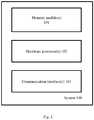
- FIG. 1 illustrates an exemplary system for task planning in a robotic environment, according to some embodiments of the present disclosure.
- the system 100 includes one or more hardware processors 102, communication interface(s) or input/output (I/O) interface(s) 103, and one or more data storage devices or memory module 101 operatively coupled to the one or more hardware processors 102.
- the one or more hardware processors 102 can be implemented as one or more microprocessors, microcomputers, microcontrollers, digital signal processors, central processing units, state machines, graphics controllers, logic circuitries, and/or any devices that manipulate signals based on operational instructions.
- the processor(s) are configured to fetch and execute computer-readable instructions stored in the memory.
- the system 100 can be implemented in a variety of computing systems, such as laptop computers, notebooks, hand-held devices, workstations, mainframe computers, servers, a network cloud and the like.
- the communication interface(s) 103 can include a variety of software and hardware interfaces, for example, a web interface, a graphical user interface, and the like and can facilitate multiple communications within a wide variety of networks N/W and protocol types, including wired networks, for example, LAN, cable, etc., and wireless networks, such as WLAN, cellular, or satellite.
- the communication interface(s) 103 can include one or more ports for connecting a number of devices to one another or to another server.
- the memory module(s) 101 may include any computer-readable medium known in the art including, for example, volatile memory, such as static random access memory (SRAM) and dynamic random access memory (DRAM), and/or non-volatile memory, such as read only memory (ROM), erasable programmable ROM, flash memories, hard disks, optical disks, and magnetic tapes.
- volatile memory such as static random access memory (SRAM) and dynamic random access memory (DRAM)
- non-volatile memory such as read only memory (ROM), erasable programmable ROM, flash memories, hard disks, optical disks, and magnetic tapes.
- ROM read only memory
- erasable programmable ROM erasable programmable ROM
- the system 100 is configured to perform the robotic task planning, which is explained in description of FIG. 2 to FIG. 6 .
- the system 100 may be implemented in a plurality of ways.
- the system 100 is configured to be in communication with a plurality of robots in a robotic environment, and is further configured to perform the task planning for each of the plurality of robots.
- one system 100 each is part of each of the plurality of robots, which enables each of the plurality of robots to perform the task planning (and execution) which allows each of the plurality of robots to perform tasks without requiring real-time control or coordination from any external entity (wherein the term 'external entity' can refer to another robot, and/or a central command centre). Functions of each component of the system 100 of FIG.
- FIG. 11 depicts data flow associated with various stages of the task planning being performed by the system 100, in an example mode of implementation, the various steps of which are explained in conjunction with the method steps depicted from FIG. 2 to FIG. 6 .
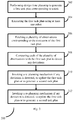
- FIG. 2 is a flow diagram depicting steps involved in the process of task planning using the system of FIG. 1 , according to some embodiments of the present disclosure.
- the system 100 When a task is assigned to a robot, the system 100 initially performs (202) design time planning to generate a first task plan corresponding to the task assigned. During the design time planning, the system 100 defines a 'problem domain' matching the assigned task.
- the 'problem domain' consists of information related to types of objects in the domain, state information corresponding to each of the objects provided as 'predicates' and information on action transitions that result in state changes defined as 'durative-actions'.
- the objecttype may correspond to the robot, an item to be picked up, etc.
- the state information of any object at any given point of time represents/indicates state in which that particular object is in, during that instance.
- the predicates are used in describing the durative-actions, which specify the condition and effect of transitions.
- the actions are specified with a duration, with predicates used to describe conditions and effects that happen at start, at end, and overall the durative action.
- the code snippet given below represents this process.
- Information pertaining to description of a problem to be solved in response to the task assigned is fed as input for the task planning.
- the 'description of the problem' may contain data such as but not limited to objects, initial state/stage of each of the objects, goal state/stage, and metrics to be planned for.
- the 'metrics' contain 'metric conditions' which convey specific requirements. For example, if the task plan is to be designed/generated such that overall task time is reduced, then this requirement forms one of the metric conditions to be satisfied during the task planning.
- the code snippet below shows initialization of objects, goal states, and metric condition.
- the system 100 may use any suitable existing planner and planning mechanism to generate the task plan, based on the information pertaining to the planning domain and the planning problem.
- the generated task plan (also referred to as 'first task plan') specifies a sequence of actions to be executed by the robot so as to perform the assigned task. For example, if the task assigned to the robot is picking up an object from a shelf in a warehouse, the task plan specifies that the robot has to move in certain direction for certain distance so as to reach a target shelf, and after reaching the location of the shelf the robot needs to detect the object, and then grab the object by moving the arm, and then direction and path plan (in terms of direction and distance) to reach a location where the grabbed object is to be dropped/placed, and then drop/place the object.
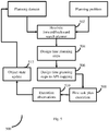
- Such steps in the task plan are referred to as "design time plan steps”. This process of generating the (first) task plan is depicted in FIG. 4 , and the code snippet given below shows an example of such a task plan generated by the system 100.
- L ⁇ p 1 , p 2, ... ... p n ⁇ be a finite set of proposition symbols.
- the planning problem considered is a triple where s 0 is an initial state and is a member of S.
- g is a subset of L and is a set of propositions known as goal propositions that give the requirements that a state must satisfy in order to be a goal state.
- g is a subset of s ⁇
- the length of the plan is
- a solution ⁇ is redundant if there is a proper subsequence of ⁇ that is also a solution of P; ⁇ is minimal if no further solution plan for P contains fewer actions than ⁇ .
- a minimum distance from s to p denoted as ⁇ ⁇ ( s,p ), is the minimum number of actions required to reach from s to a state containing p .
- the minimum distance from s to g , ⁇ *( s,g ) is the minimum number of actions required to reach from s to a state containing all propositions in s to g .
- the system 100 estimates a heuristic estimate ⁇ using a minimum distance graph searching algorithm. This algorithm proceeds from a state s, through each action whose preconditions have been reached, until a fixed point is reached. Given a planning problem where each action a has a cost cost ( a ) , the algorithm defines distance to a proposition P or to a goal g to be the cost of achieving P or g .
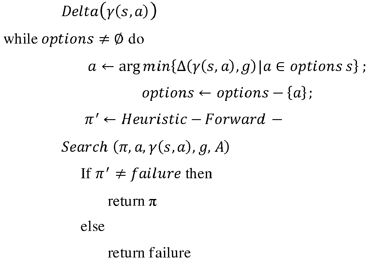
- ⁇ is the current partial plan with an initial function call Heuristic-Forward-Search ( ⁇ >, s 0 ,g, A ), where ⁇ > is an empty plan, which is iteratively updated with actions a satisfying preconditions at each step. This can be achieved using any suitable approach such as but not limited to a greedy search algorithm or with a best-first search. This knowledge is used by the system 100 during the task planning.
- the system 100 requires information pertaining to a plurality of other data during the task planning. Such data is maintained in the form of a knowledge base.
- the knowledge base provides the system 100, a consistent view of the world model, objects, state changes, robotic capabilities and algorithms of interest.
- the knowledge base is also configured to capture data pertaining to semantic relationship between the objects, robotic entities and tasks. In order to capture this, the system 100 may use graph databases, that store data and semantic relationships graphically - the nodes and execution of tasks.
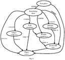
- An example of the knowledge base is depicted in FIG. 6 .
- two types of events cause changes in the knowledge base: actions and perceptions. While the actions cause changes in state of the objects, the perceptions causes current object state to be recorded.
- This data may be queries to extract information pertaining to current state and details of objects in the world model.
- An example of querying currentState of objects using Gremlin query language is given below:
- the system 100 may be configured to generate task plans on the fly i.e. the system 100 can generate a new task plan if required, or may update an existing task plan as needed.
- the system 100 may also maintain a domain file consisting: (a) Action description, describing a possible action that may be performed in relation to an environment, (b) Precondition, a conjunction of atoms which specify what must be true before an operator may be applied, (c) Effects, is a conjunction of literals which define situation changes after application of an operator.
- This data along with a problem file consisting object and state initialization, goal conditions and minimization metrics is input for dynamic/on the fly task planning, using any appropriate technique.
- a state of art Planning Domain Definition Language (PDDL) can be used for the dynamic task planning. All such information may be further used by the system 100 for the design-time planning.
- PDDL Planning Domain Definition Language
- each of a plurality of design time plan steps is mapped to corresponding Application Programming Interface (API), based on the information populated in an associated knowledge base (example of such a knowledge base is depicted in FIG. 6 ).
- API Application Programming Interface
- the code snippet given below represents an example of plan execution/orchestration by a robot.
- the system 100 fetches (206) information pertaining to a plurality of observations corresponding to the execution of the first task plan.
- the term 'observation' in this context refers to state changes during execution of each of the design time plan steps that form the first task plan.
- the system 100 compares (208) each of the plurality of observations with the first task plan to detect any deviations.
- the first task plan comprises an expected state change, action, corresponding to each of the design plan steps.
- the system 100 checks for any deviation between the fetched observations and that in the first task plan.
- the deviation may be in terms of at least one of a. state change of one or more objects, b.
- the system 100 invokes (210) a re-planning mechanism to dynamically adjust to the change in environment (due to the state change or due to presence of the new object). If no deviation is detected, then the first task plan is continued.
- the system 100 by virtue of the re-planning mechanism, the system 100 either updates/modifies the first task plan (an updated first task plan), or generates a second task plan. Details of the re-planning mechanism are covered in description of FIG. 3 .
- the updated first task plan or the second task plan is further executed by the robot to reach one or more goals associated with the assigned task.
- An algorithm that may be executed by the system 100 for the task planning, adaptation and re-planning is given below:
- the system 100 may perform the heuristic search by executing the algorithm given below:
- the steps in method 200 may be performed in the same order or in any possible alternate order. In another embodiment, one or more steps in method 200 may be skipped.
- FIG. 3 is a flow diagram depicting steps involved in the process of performing a re-planning, using the system of FIG. 1 , in accordance with some embodiments of the present disclosure.
- the system 100 determines (302) type of deviation as one of: state of change of at least one object, presence of at least one new object, and/or failure of at least one action in the first action plan. If the deviation is in terms of state of change of at least one object, then the system 100 updates (304) the planning domain by capturing/including details of the determined state change, and then uses the updated planning domain as input to generate the task plan, which is the updated first task plan.
- This process is depicted in FIG. 5 .
- An example of the state change is the first task plan expects an object 'door' in path of the robot to remain open. However if during the execution of the first task plan the door is detected as in a 'closed' state, then it is a deviation.
- the system 100 triggers (308) one or more perception queries to collect details of the one or more new objects. Further, the collected details are used to form the planning problem and the problem domain, which is then used to generate (310) a second task plan.
- the system 100 prioritizes and executes/performs only certain important actions. This is achieved based on information pertaining to priority of the actions, which may be pre -defined or dynamically defined. In case an action failure is detected, then the system 100 may skip certain steps, with a trade-off between accuracy, computational cost, and time required.
- the priority of actions may change based on requirements. For example, if time is a constraint, and accuracy can be compromised, then the actions are prioritized such that the task is executed within a certain period of time, with lesser accuracy.
- the requirements/criteria may be defined/specified in terms of the metric conditions. This process is explained further with reference to FIG.
- the system 100 may generate a new plan, and during the course of the new plan generation, certain 'fast' lower accuracy actions may be replaced with 'slower' high accuracy actions.
- a metric to be minimized in the problem file is modified from 'minimizing time' to 'reducing probability of action failures'.
- the code snippet below represents a failure of an action in the first task plan (which causes the system 100 to invoke the adaptation and re-planning).
- plan execution fails at the gripping action.
- a new plan is generated, which is further executed by the system 100.
- a code snippet depicting example of an updated plan is given below:
- the steps in method 300 may be performed in the same order or in any possible alternate order. In another embodiment, one or more steps in method 300 may be skipped.
- Table. 2 describes various scenarios for the system 100 to plan and execute. Table. 2 Problem Robot entities Mobility Target Obstacles 1 Single No Single No 2 Single Yes Single No 3 Single Yes Single Yes 4 Single Yes Multiple Yes 5 Multiple Yes Multiple Yes
- FIG. 9 A time-line of performing the adaptive sequence with exponentially distributed execution times is presented in FIG. 9 (a, b, and c). The values indicated that there was a deterioration by 28% in overall latency for this run, when two stages of adaptation and re-planning occurred.
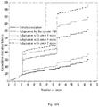
- FIG. 10A and FIG. 10B Further analysis on tradeoffs between increasing end to end execution times and probability of failures in execution are represented in FIG. 10A and FIG. 10B . It was noticed that cumulative execution times differ depending on the probabilities that execution fail to match intended plan tasks for 10000 Monte-Carlo runs. For each of these case adaptation and re-planning were invoked. For a specified planning problem, the end-t-end execution completed within 200 time units in 90% of the cases for failure probability 0.1, in 55% of the cases for failure probability 0.5, and in 25% of the cases for failure probability 0.9. These values help estimate execution times in automated tasks in warehouse environments. When there are increased level of ambiguity and possibility of obstacles, extended periods may be allocated for re-planning and adaptive execution.
- the embodiments of present disclosure herein addresses unresolved problem of task planning in a robotic environment.
- the embodiment thus provides a mechanism to adjust to dynamic change in environments during a task plan execution, by providing an adaptation and re-planning mechanism.
- the embodiments herein further provides a way of updating an existing task plan or creating a new one so as to capture the change in environment during the task plan execution.
- the hardware device can be any kind of device which can be programmed including e.g. any kind of computer like a server or a personal computer, or the like, or any combination thereof.
- the device may also include means which could be e.g. hardware means like e.g. an application-specific integrated circuit (ASIC), a field-programmable gate array (FPGA), or a combination of hardware and software means, e.g.
- ASIC application-specific integrated circuit
- FPGA field-programmable gate array
- the means can include both hardware means and software means.
- the method embodiments described herein could be implemented in hardware and software.
- the device may also include software means.
- the embodiments may be implemented on different hardware devices, e.g. using a plurality of CPUs.
- the embodiments herein can comprise hardware and software elements.
- the embodiments that are implemented in software include but are not limited to, firmware, resident software, microcode, etc.
- the functions performed by various components described herein may be implemented in other components or combinations of other components.
- a computer-usable or computer readable medium can be any apparatus that can comprise, store, communicate, propagate, or transport the program for use by or in connection with the instruction execution system, apparatus, or device.
- a computer-readable storage medium refers to any type of physical memory on which information or data readable by a processor may be stored.
- a computer-readable storage medium may store instructions for execution by one or more processors, including instructions for causing the processor(s) to perform steps or stages consistent with the embodiments described herein.
- the term "computer-readable medium” should be understood to include tangible items and exclude carrier waves and transient signals, i.e., be non-transitory. Examples include random access memory (RAM), read-only memory (ROM), volatile memory, nonvolatile memory, hard drives, CD ROMs, DVDs, flash drives, disks, and any other known physical storage media.
Landscapes
- Engineering & Computer Science (AREA)
- Robotics (AREA)
- Mechanical Engineering (AREA)
- Software Systems (AREA)
- Theoretical Computer Science (AREA)
- Manipulator (AREA)
- Physics & Mathematics (AREA)
- General Engineering & Computer Science (AREA)
- General Physics & Mathematics (AREA)
- Human Computer Interaction (AREA)
- Control Of Position, Course, Altitude, Or Attitude Of Moving Bodies (AREA)
Abstract
Description
- This EPO patent application claims priority under 35 U.S.C. § 119 to: India Application No.
201921030817, filed on 30-Jul-2019 - The disclosure herein generally relates to robotics, and, more particularly, to a method and system for task planning in a robotic environment.
- Robots are used in various domains for the purpose of automating various activities. For example, robots are used in warehouses to handle picking, placing, and even packing of items/goods for which customer order may have been received. When any such task is assigned to a robot, task planning is one of the primary steps to be carried out. During the task planning, a task plan is generated which is further executed by the robot so as to perform the assigned task. For example, when a robot is to pick an item placed in a particular shelf in the warehouse, the robot needs to be aware of exact location of the item (which may be defined in terms of shelf number, and raw and column numbers), as well as route to reach that particular location.
- In some of the existing systems, a centralized system manages the task planning activity. Disadvantage of such systems is that the robots deployed for task execution are required to be in communication with the centralized system, which means if the connection is terminated/interrupted (due to bad network or any other reason), the task execution is adversely affected. Such systems may also require user intervention during the task planning. Also, when the robots operate on a fixed plan, they fail to capture any change in any of the parameters associated with the plan, which may result in failure of the plan.
- Embodiments of the present disclosure present technological improvements as solutions to one or more of the above-mentioned technical problems recognized by the inventors in conventional systems. For example, in one embodiment, a processor implemented method for task planning and execution in a robotic environment is provided. In this method, a design time planning is performed to generate a first task plan corresponding to a task, via one or more hardware processors. Further, the first task plan is executed using at least one robot in the robotic environment, via the one or more hardware processors. Further, a plurality of observations corresponding to the execution of the first task plan are fetched, via the one or more hardware processors. Then each of the plurality of observations is compared with the first task plan to detect any deviation from the first task plan, via the one or more hardware processors, and if any deviation is detected, a re-planning mechanism is invoked, via the one or more hardware processors. During the re-planning mechanism, it is determined whether the deviation is caused due to state change of any existing object or due to presence of any new object, or due to failure of at least one of a plurality of actions in the first task plan. If the deviation is caused due to state change of at least one object, then the first task plan is updated to capture the state change of the at least one object and then the updated first task plan is executed using the at least one robot, via the one or more hardware processors. If the deviation is caused due to presence of at least one new object, then one or more perception queries are triggered to collect details of the at least one new object, and then a second task plan capturing the details of the at least one new object is generated. Then the second task plan is executed using the at least one robot, via the one or more hardware processors. If the deviation is caused due to failure of at least one of a plurality of actions in the first task plan, then one of a low granularity approach or a high granularity approach is selected and executed to update the first task plan.
- In another aspect, a system is provided. The system comprising one or more communication interfaces, one or more hardware processors, and one or more memory modules storing a plurality of instructions, wherein said plurality of instructions, when executed, cause the one or more hardware processors to perform a design time planning to generate a first task plan corresponding to a task; execute the first task plan using at least one robot in the robotic environment; fetch a plurality of observations corresponding to the execution of the first task plan; compare each of the plurality of observations with the first task plan to detect any deviation from the first task plan; and invoke a re-planning mechanism if any deviation is detected. During the re-planning mechanism, it is determined whether the deviation is caused due to state change of any existing object or due to presence of any new object, or due to failure of at least one of a plurality of actions in the first task plan. If the deviation is caused due to state change of at least one object, then the first task plan is updated to capture the state change of the at least one object and then the updated first task plan is executed using the at least one robot, via the one or more hardware processors. If the deviation is caused due to presence of at least one new object, then one or more perception queries are triggered to collect details of the at least one new object, and then a second task plan capturing the details of the at least one new object is generated. Then the second task plan is executed using the at least one robot, via the one or more hardware processors. If the deviation is caused due to failure of at least one of a plurality of actions in the first task plan, then one of a low granularity approach or a high granularity approach is selected and executed to update the first task plan.
- In yet another aspect, a non-transitory computer readable medium for task planning and execution in a robotic environment is provided. The non -transitory computer readable medium performs a design time planning to generate a first task plan corresponding to a task, via one or more hardware processors. Further, the non-transitory computer readable medium executes the first task plan using at least one robot in the robotic environment, via the one or more hardware processors. Further, a plurality of observations corresponding to the execution of the first task plan are fetched, via the one or more hardware processors. Then each of the plurality of observations is compared with the first task plan to detect any deviation from the first task plan, via the one or more hardware processors, and if any deviation is detected, a re-planning mechanism is invoked, via the one or more hardware processors. During the re-planning mechanism, it is determined whether the deviation is caused due to state change of any existing object or due to presence of any new object, or due to failure of at least one of a plurality of actions in the first task plan. If the deviation is caused due to state change of at least one object, then the first task plan is updated to capture the state change of the at least one object and then the updated first task plan is executed using the at least one robot, via the one or more hardware processors. If the deviation is caused due to presence of at least one new object, then one or more perception queries are triggered to collect details of the at least one new object, and then a second task plan capturing the details of the at least one new object is generated. Then the second task plan is executed using the at least one robot, via the one or more hardware processors. If the deviation is caused due to failure of at least one of a plurality of actions in the first task plan, then one of a low granularity approach or a high granularity approach is selected and executed to update the first task plan.
- It is to be understood that both the foregoing general description and the following detailed description are exemplary and explanatory only and are not restrictive of the invention, as claimed.
- The accompanying drawings, which are incorporated in and constitute a part of this disclosure, illustrate exemplary embodiments and, together with the description, serve to explain the disclosed principles:
-
FIG. 1 illustrates an exemplary system for task planning in a robotic environment, according to some embodiments of the present disclosure. -
FIG. 2 is a flow diagram depicting steps involved in a process of task planning using the system ofFIG. 1 , according to some embodiments of the present disclosure. -
FIG. 3 is a flow diagram depicting steps involved in the process of performing a re-planning, using the system ofFIG. 1 , in accordance with some embodiments of the present disclosure. -
FIG. 4 depicts steps involved in the process of generating the first task plan by executing the design time planning, using the system ofFIG. 1 , according to some embodiments of the present disclosure. -
FIG. 5 depicts steps involved in the process of updating the first task plan, using the system ofFIG. 1 , in accordance with some embodiments of the present disclosure. -
FIG. 6 is an example of knowledgebase being used by the system ofFIG. 1 , for the task planning, in accordance with some embodiments of the present disclosure. -
FIG. 7 depicts an example of priority based selection of actions for execution, in the event of failure of one or more actions in the first task plan, by the system ofFIG. 1 , in accordance with some embodiments of the present disclosure. -
FIG. 8 depicts an example scenario of picking and placing an object from a rack in a warehouse, where the task planning can be performed using the system ofFIG. 1 , in accordance with some embodiments of the present disclosure. -
FIGS. 9 (a, b, and c) are graphical representations of additional time duration caused due to re-planning of a task in different example scenarios, using the system ofFIG. 1 , in accordance with some embodiments of the present disclosure. -
FIG. 10A is a graphical representation of execution timelines for simple and adaptive plans, using the system ofFIG. 1 , in accordance with some embodiments of the present disclosure. -
FIG. 10B is a graphical representation of execution times with plan failures, using the system ofFIG. 1 , in accordance with some embodiments of the present disclosure. - Exemplary embodiments are described with reference to the accompanying drawings. In the figures, the left-most digit(s) of a reference number identifies the figure in which the reference number first appears. Wherever convenient, the same reference numbers are used throughout the drawings to refer to the same or like parts. While examples and features of disclosed principles are described herein, modifications, adaptations, and other implementations are possible without departing from the scope of the disclosed embodiments. It is intended that the following detailed description be considered as exemplary only, with the true scope being indicated by the following claims.
- Referring now to the drawings, and more particularly to
FIG. 1 through FIG. 10B , where similar reference characters denote corresponding features consistently throughout the figures, there are shown preferred embodiments and these embodiments are described in the context of the following exemplary system and/or method. -
FIG. 1 illustrates an exemplary system for task planning in a robotic environment, according to some embodiments of the present disclosure. - The
system 100 includes one ormore hardware processors 102, communication interface(s) or input/output (I/O) interface(s) 103, and one or more data storage devices ormemory module 101 operatively coupled to the one ormore hardware processors 102. The one ormore hardware processors 102 can be implemented as one or more microprocessors, microcomputers, microcontrollers, digital signal processors, central processing units, state machines, graphics controllers, logic circuitries, and/or any devices that manipulate signals based on operational instructions. Among other capabilities, the processor(s) are configured to fetch and execute computer-readable instructions stored in the memory. In an embodiment, thesystem 100 can be implemented in a variety of computing systems, such as laptop computers, notebooks, hand-held devices, workstations, mainframe computers, servers, a network cloud and the like. - The communication interface(s) 103 can include a variety of software and hardware interfaces, for example, a web interface, a graphical user interface, and the like and can facilitate multiple communications within a wide variety of networks N/W and protocol types, including wired networks, for example, LAN, cable, etc., and wireless networks, such as WLAN, cellular, or satellite. In an embodiment, the communication interface(s) 103 can include one or more ports for connecting a number of devices to one another or to another server.
- The memory module(s) 101 may include any computer-readable medium known in the art including, for example, volatile memory, such as static random access memory (SRAM) and dynamic random access memory (DRAM), and/or non-volatile memory, such as read only memory (ROM), erasable programmable ROM, flash memories, hard disks, optical disks, and magnetic tapes. In an embodiment, one or more modules (not shown) of the
system 100 can be stored in thememory 101. - The
system 100 is configured to perform the robotic task planning, which is explained in description ofFIG. 2 to FIG. 6 . Thesystem 100 may be implemented in a plurality of ways. In an embodiment, thesystem 100 is configured to be in communication with a plurality of robots in a robotic environment, and is further configured to perform the task planning for each of the plurality of robots. In another embodiment, onesystem 100 each is part of each of the plurality of robots, which enables each of the plurality of robots to perform the task planning (and execution) which allows each of the plurality of robots to perform tasks without requiring real-time control or coordination from any external entity (wherein the term 'external entity' can refer to another robot, and/or a central command centre). Functions of each component of thesystem 100 ofFIG. 1 are explained in conjunction with the method steps depicted fromFIG. 2 to FIG. 6 . Also,FIG. 11 depicts data flow associated with various stages of the task planning being performed by thesystem 100, in an example mode of implementation, the various steps of which are explained in conjunction with the method steps depicted fromFIG. 2 to FIG. 6 . -
FIG. 2 is a flow diagram depicting steps involved in the process of task planning using the system ofFIG. 1 , according to some embodiments of the present disclosure. When a task is assigned to a robot, thesystem 100 initially performs (202) design time planning to generate a first task plan corresponding to the task assigned. During the design time planning, thesystem 100 defines a 'problem domain' matching the assigned task. The 'problem domain' consists of information related to types of objects in the domain, state information corresponding to each of the objects provided as 'predicates' and information on action transitions that result in state changes defined as 'durative-actions'. The objecttype may correspond to the robot, an item to be picked up, etc. which may form part of the task plan in terms of presence in an area where the task is to be executed, or in terms of an action to be performed on as part of the task. The state information of any object at any given point of time represents/indicates state in which that particular object is in, during that instance. The predicates are used in describing the durative-actions, which specify the condition and effect of transitions. The actions are specified with a duration, with predicates used to describe conditions and effects that happen at start, at end, and overall the durative action. The code snippet given below represents this process.
 (:types world_model robot gripper hold_target operate_target control_target
            goal_target)
            (:predicates (non - perceived ?a - world_model)
            (perceived ?a - world_model)
            (undetected ?d - hold_target
            ?b - robot)
            (detected ?d - hold_target ?b - robot))
            (:durative-action Detection_high
     :parameters (?d - hold_target ?f - operate_target
                  ?m - control_target ?b - robot)
     :duration (= ?duration 100)
         :condition (and (at start (undetected ?d ?b))
         (at start (reach - target - position ?b))
         (over all (opened ?f))
         (over all (unlocked ?m)))
     :effect (and (at end (detected ?d ?b))
            (at end (not (undetected ?d ?b)))
  (at end (increase (action_cost) 80))))


- S = {s1, s2, ... sn} is a finite set of states;
- A = {a1, a2, ... am} is a finite set of actions;
- γ: S ∗ A ∗ E → 2 s → is a state transition function.
- Each state s ∈ S is a subset of 2 L . If p ∈ s, then proposition p holds in state of the world represented by s.
- Each action a ∈ A is a triple of subsets L, represented as a = (precond (a), effects- (a), effects+ (a)). The set precond(a) is called preconditions of a, and the sets effects -(a), effects +(a) are called effects of a. These two sets of effects are disjoint sets effects+ (a) ∩ effects- (a) = ∅. The action a is applicable to a state s if precond(a) is a subset of s.
- S has a property that if s ε S, then, for every action a that is applicable to s, the set of (s - effects- (a)) ∪ effects+ (a)εS i.e. whenever an action is applicable to a state, it produces another state.


     gremlin> g.V.has('key','World_Model').
     outE('currentState').in V.key
     ==>Non-Perceived
     gremlin> g.V.has('key','Robot-Location').
     outE('currentState').in V.key
     ==>Robot-Home-Position
     gremlin> g.V.has('key','Target-Location').
     outE('currentState').in V.key
     ==>Off - Target
| Category | Action task | Orchestrated API call |
| Perception | Perception | robot.camera_id.sensing >> |
| robot.camera.id.edge detection >> | ||
| knowledge_base_query | ||
| Base movement | Robot_movement | robot.mobile_base.path-planning >> |
| robot.mobile_base.move-to-location | ||
| robot.gripper.movement-planning >> | ||
| Manipulation | Robot_arm_movement | robot.gripper.movement |
| robot.gripper.grasping-planning >> | ||
| Gripper_grasp | robot.gripper.open-palm >> | |
| robot.gripper.close-palm | ||
| Gripper_ungrasp | robot.gripper.ungrasp-planning >> | |
| robot.gripper.open-palm |




- 60 .000: Gripper grasp slow World Youbot_gripper1
- Youbot Ball1 Door Cupboard
- 90 .000: Holding object slow World Youbot Ball1 Door
- Cupboard Youbot_gripper1
- 150 .000: Perception_low World
- 190 .000: Robot movement goal slow World
- Youbot Door
- 280 .000: Gripper ungrasp slow World Youbot_gripper1
- Youbot Ball1 Door Cupboard
- 194 API robot.camera_id.sensing
- 196 API robot.camera_id.edge_detection
- 198 API Knowledge_base_query
- 225 Success Perception 24 seconds
- 228 Current World State perceived
-- ------------------------ - 232 API robot.mobile_base.path - planning
- 234 API robot.mobile_base.move -to - location home
| Problem | Robot entities | | Target | Obstacles | |
| 1 | Single | | Single | No | |
| 2 | Single | | Single | No | |
| 3 | Single | Yes | Single | Yes | |
| 4 | Single | Yes | | Yes | |
| 5 | Multiple | Yes | Multiple | Yes |
Claims (9)
- A processor implemented method for task planning and execution in a robotic environment, comprising:performing a design time planning to generate a first task plan corresponding to a task, via one or more hardware processors;executing the first task plan using at least one robot in the robotic environment, via the one or more hardware processors;fetching a plurality of observations corresponding to the execution of the first task plan, via the one or more hardware processors;comparing each of the plurality of observations with the first task plan to detect any deviation from the first task plan, via the one or more hardware processors; andinvoking a re-planning mechanism if any deviation is detected, via the one or more hardware processors, wherein the re-planning mechanism comprises:determining whether the deviation is caused due to state change of any existing object or due to presence of any new object, or due to failure of at least one of a plurality of actions in the first task plan, whereinif the deviation is caused due to state change of at least one object:updating the first task plan to capture the state change of the at least one object; andexecuting the updated first task plan using the at least one robot, via the one or more hardware processors;if the deviation is caused due to presence of at least one new object:triggering one or more perception queries to collect details of the at least one new object;generating a second task plan capturing the details of the at least one new object; andexecuting the second task plan using the at least one robot, via the one or more hardware processors; andif at least one of a plurality of actions in the first task plan fails:selecting one of a low granularity approach or a high granularity approach;andexecuting the selected low granularity approach or a high granularity approach to update the first task plan.
- The method as claimed in claim 1, wherein generating the first task plan by performing a design time planning comprises:collecting information pertaining to a planning domain and a planning problem associated with the task, as inputs;performing a heuristic forward/backward search planning on the collected information to determine a plurality of design time plan steps; andmappingeach of the plurality of design time plan steps with corresponding Application Programing Interface (API).
- The method as claimed in claim 1, wherein updating the first task plan to capture the state change of the at least one object comprising:updating the information pertaining to the planning domain with information pertaining to state change of the at least one object, to generate an updated planning domain;performing the heuristic forward/backward search planning on the updated planning domain and the planning problem to generate a plurality of updated design time planning steps; andmapping each of the plurality of updated design time plan steps with corresponding Application Programing Interface (API).
- A system for robotic task planning, comprising:one or more communication interfaces (103);one or more hardware processors (102); andone or more memory modules (101) storing a plurality of instructions, wherein said plurality of instructions, when executed, cause the one or more hardware processors (102) to:perform a design time planning to generate a first task plan corresponding to a task;execute the first task plan using at least one robot in the robotic environment;fetch a plurality of observations corresponding to the execution of the first task plan;compare each of the plurality of observations with the first task plan to detect any deviation from the first task plan; andinvoke a re-planning mechanism if any deviation is detected, wherein the re-planning mechanism comprises:determining whether the deviation is caused due to state change of any existing object, or due to presence of any new object, or due to failure of at least one of a plurality of actions in the first task plan, whereinif the deviation is caused due to state change of at least one object:updating the first task plan to capture the state change of the at least one object; andexecuting the updated first task plan using the at least one robot;if the deviation is caused due to presence of at least one new object triggering one or more perception queries to collect details of the at least one new object;generating a second task plan capturing the details of the at least one new object; andexecuting the second task plan using the at least one robot; andif at least one of a plurality of actions in the first task plan fails:selecting one of a low granularity approach or a high granularity approach;andexecuting the selected low granularity approach or a high granularity approach to update the first task plan.
- The system as claimed in claim 4, wherein the robotgenerates the firsttask plan by executing the design time planning, comprising:collecting information pertaining to a planning domain and a planning problem corresponding to the task, as inputs;performing a heuristic forward/backward search planning on the collected information to determine a plurality of design time plan steps; andmappingeach of the plurality of design time plan steps with corresponding Application Programing Interface (API).
- The system as claimed in claim 4, wherein the robot updates the first task plan to capture the state change of the at least one object by:updating the information pertaining to the planning domain with information pertaining to state change of the at least one object, to generate an updated planning domain;performing the heuristic forward/backward search planning on the updated planning domain and the planning problem to generate a plurality of updated design time planning steps; andmapping each of the plurality of updated design time plan steps with corresponding Application Programing Interface (API).
- A non-transitory computer readable medium for task planning and execution in a robotic environment, wherein the task planning and execution comprising:performing a design time planning to generate a first task plan corresponding to a task, via one or more hardware processors;executing the first task plan using at least one robot in the robotic environment, via the one or more hardware processors;fetching a plurality of observations corresponding to the execution of the first task plan, via the one or more hardware processors;comparing each of the plurality of observations with the first task plan to detect any deviation from the first task plan, via the one or more hardware processors; andinvoking a re-planning mechanism if any deviation is detected, via the one or more hardware processors, wherein the re-planning mechanism comprises:determining whether the deviation is caused due to state change of any existing object or due to presence of any new object, or due to failure of at least one of a plurality of actions in the first task plan, whereinif the deviation is caused due to state change of at least one object:updating the first task plan to capture the state change of the at least one object; andexecuting the updated first task plan using the at least one robot, via the one or more hardware processors;if the deviation is caused due to presence of at least one new object:triggering one or more perception queries to collect details of the at least one new object;generating a second task plan capturing the details of the at least one new object; andexecuting the second task plan using the at least one robot, via the one or more hardware processors; andif at least one of a plurality of actions in the first task plan fails:selecting one of a low granularity approach or a high granularity approach;andexecuting the selected low granularity approach or a high granularity approach to update the first task plan.
- The non-transitory computer readable medium as claimed in claim 7, wherein generating the first task plan by performing a design time planning comprises:collecting information pertaining to a planning domain and a planning problem associated with the task, as inputs;performing a heuristic forward/backward search planning on the collected information to determine a plurality of design time plan steps; andmappingeach of the plurality of design time plan steps with corresponding Application Programing Interface (API).
- The non-transitory computer readable medium as claimed in claim 7, wherein updating the first task plan to capture the state change of the at least one object comprising:updating the information pertaining to the planning domain with information pertaining to state change of the at least one object, to generate an updated planning domain;performing the heuristic forward/backward search planning on the updated planning domain and the planning problem to generate a plurality of updated design time planning steps; andmapping each of the plurality of updated design time plan steps with corresponding Application Programing Interface (API).
Applications Claiming Priority (1)
| Application Number | Priority Date | Filing Date | Title |
|---|---|---|---|
| IN201921030817 | 2019-07-30 |
Publications (3)
| Publication Number | Publication Date |
|---|---|
| EP3771523A1 true EP3771523A1 (en) | 2021-02-03 |
| EP3771523C0 EP3771523C0 (en) | 2025-07-16 |
| EP3771523B1 EP3771523B1 (en) | 2025-07-16 |
Family
ID=71894615
Family Applications (1)
| Application Number | Title | Priority Date | Filing Date |
|---|---|---|---|
| EP20188501.9A Active EP3771523B1 (en) | 2019-07-30 | 2020-07-30 | Method and system for robotic task planning |
Country Status (2)
| Country | Link |
|---|---|
| US (1) | US11602847B2 (en) |
| EP (1) | EP3771523B1 (en) |
Cited By (2)
| Publication number | Priority date | Publication date | Assignee | Title |
|---|---|---|---|---|
| CN113650808A (en) * | 2021-08-19 | 2021-11-16 | 北京市遥感信息研究所 | Task-driven remote sensing satellite dynamic emergency method and system |
| CN118504816A (en) * | 2024-04-25 | 2024-08-16 | 中国科学院计算技术研究所 | Reactive planning method and system based on large language model |
Families Citing this family (16)
| Publication number | Priority date | Publication date | Assignee | Title |
|---|---|---|---|---|
| JP7204631B2 (en) * | 2019-10-29 | 2023-01-16 | 株式会社東芝 | TRIP CONTROL DEVICE, METHOD AND COMPUTER PROGRAM |
| WO2021211028A1 (en) * | 2020-04-17 | 2021-10-21 | Telefonaktiebolaget Lm Ericsson (Publ) | Network node and method for handling operations in a communications network |
| US11551183B2 (en) | 2020-09-21 | 2023-01-10 | 6 River Systems, Llc | Systems and methods for managing exceptions to orders collected by autonomous vehicles |
| US20220362928A1 (en) * | 2021-05-11 | 2022-11-17 | Rapyuta Robotics Co., Ltd. | System and method for generating and displaying targeted information related to robots in an operating environment |
| US11676101B2 (en) * | 2021-06-16 | 2023-06-13 | 6 River Systems, Llc | Systems and methods for using kits as a source of inventory in a fulfillment center |
| US12086760B2 (en) | 2021-06-16 | 2024-09-10 | Ocado Innovation Limited | Systems and methods for dynamic management of consolidation orders |
| US12093866B2 (en) * | 2021-06-16 | 2024-09-17 | Ocado Innovation Limited | Systems and methods for optimizing assembly of product kits in an order fulfillment center using autonomous vehicles |
| US12145803B1 (en) * | 2021-06-21 | 2024-11-19 | Amazon Technologies, Inc. | Item and container tracking with task planning |
| WO2023055857A1 (en) * | 2021-09-28 | 2023-04-06 | Intrinsic Innovation Llc | Online planning satisfying constraints |
| US12605830B2 (en) * | 2022-12-30 | 2026-04-21 | Intrinsic Innovation Llc | Robot planning for gaps |
| US20240217100A1 (en) * | 2022-12-30 | 2024-07-04 | Intrinsic Innovation Llc | Feature interfaces for real-time robotics control |
| CN117008598A (en) * | 2023-01-03 | 2023-11-07 | 北京石头创新科技有限公司 | Methods, devices and self-moving equipment for moving equipment to a designated location |
| CN116451563A (en) * | 2023-03-22 | 2023-07-18 | 之江实验室 | Ontology design method and device for describing robot capability |
| US20240367316A1 (en) * | 2023-05-05 | 2024-11-07 | Sanctuary Cognitive Systems Corporation | Multi-purpose robots, systems, computer program products, and methods for evaluating state representations of the same |
| KR20250075294A (en) * | 2023-11-21 | 2025-05-28 | 한국전자통신연구원 | Apparatus and method for generating task plan |
| CN121353989B (en) * | 2025-11-12 | 2026-05-01 | 哈尔滨工业大学(威海) | Long video motion planning method and equipment based on hierarchical re-planning architecture |
Citations (2)
| Publication number | Priority date | Publication date | Assignee | Title |
|---|---|---|---|---|
| EP2829939A1 (en) * | 2005-12-02 | 2015-01-28 | iRobot Corporation | Autonomous coverage robot navigation system |
| US20150314449A1 (en) * | 2011-01-28 | 2015-11-05 | Irobot Corporation | Interfacing with a mobile telepresence robot |
Family Cites Families (8)
| Publication number | Priority date | Publication date | Assignee | Title |
|---|---|---|---|---|
| US10105844B2 (en) * | 2016-06-16 | 2018-10-23 | General Electric Company | System and method for controlling robotic machine assemblies to perform tasks on vehicles |
| KR20120061014A (en) | 2010-11-03 | 2012-06-12 | 한국전자통신연구원 | System for robot task planning based on description logic knowledgebase |
| WO2016149557A1 (en) * | 2015-03-17 | 2016-09-22 | Vm-Robot, Inc. | Web browsing robot system and method |
| KR20170095583A (en) | 2016-02-15 | 2017-08-23 | 한국전자통신연구원 | Apparatus and method for adaptive task planning of robot |
| DE102017109219A1 (en) * | 2017-04-28 | 2018-10-31 | RobArt GmbH | Method for robot navigation |
| US10496095B1 (en) * | 2017-11-07 | 2019-12-03 | United States Of America As Represented By The Secretary Of The Navy | Autonomous agent scheduling |
| US10740572B2 (en) * | 2018-05-02 | 2020-08-11 | International Business Machines Corporation | Using robot plans as parallel linguistic corpora |
| EP3590664B1 (en) * | 2018-07-02 | 2024-09-04 | Tata Consultancy Services Limited | Method and system for hierarchical decomposition of tasks and action planning in a robotic network |
-
2020
- 2020-07-29 US US16/942,433 patent/US11602847B2/en active Active
- 2020-07-30 EP EP20188501.9A patent/EP3771523B1/en active Active
Patent Citations (2)
| Publication number | Priority date | Publication date | Assignee | Title |
|---|---|---|---|---|
| EP2829939A1 (en) * | 2005-12-02 | 2015-01-28 | iRobot Corporation | Autonomous coverage robot navigation system |
| US20150314449A1 (en) * | 2011-01-28 | 2015-11-05 | Irobot Corporation | Interfacing with a mobile telepresence robot |
Non-Patent Citations (3)
| Title |
|---|
| BLENDER TIMO ET AL: "Managing a Mobile Agricultural Robot Swarm for a seeding task", IECON 2016 - 42ND ANNUAL CONFERENCE OF THE IEEE INDUSTRIAL ELECTRONICS SOCIETY, IEEE, 23 October 2016 (2016-10-23), pages 6879 - 6886, XP033033840, DOI: 10.1109/IECON.2016.7793638 * |
| GARRETT CAELAN REED ET AL: "Backward-forward search for manipulation planning", 2015 IEEE/RSJ INTERNATIONAL CONFERENCE ON INTELLIGENT ROBOTS AND SYSTEMS (IROS), IEEE, 28 September 2015 (2015-09-28), pages 6366 - 6373, XP032832555, DOI: 10.1109/IROS.2015.7354287 * |
| PIN F G ET AL: "ON THE DESIGN AND DEVELOPMENT OF A HUMAN-ROBOT SYNERGISTIC SYSTEM", ROBOTICS AND AUTONOMOUS SYSTEMS, ELSEVIER BV, AMSTERDAM, NL, vol. 10, no. 2 / 03, 1 January 1992 (1992-01-01), pages 161 - 184, XP000320103, ISSN: 0921-8890, DOI: 10.1016/0921-8890(92)90024-S * |
Cited By (3)
| Publication number | Priority date | Publication date | Assignee | Title |
|---|---|---|---|---|
| CN113650808A (en) * | 2021-08-19 | 2021-11-16 | 北京市遥感信息研究所 | Task-driven remote sensing satellite dynamic emergency method and system |
| CN113650808B (en) * | 2021-08-19 | 2023-08-04 | 北京市遥感信息研究所 | Task-driven-oriented remote sensing satellite dynamic emergency method and system |
| CN118504816A (en) * | 2024-04-25 | 2024-08-16 | 中国科学院计算技术研究所 | Reactive planning method and system based on large language model |
Also Published As
| Publication number | Publication date |
|---|---|
| US20210049037A1 (en) | 2021-02-18 |
| EP3771523C0 (en) | 2025-07-16 |
| US11602847B2 (en) | 2023-03-14 |
| EP3771523B1 (en) | 2025-07-16 |
Similar Documents
| Publication | Publication Date | Title |
|---|---|---|
| US11602847B2 (en) | Method and system for robotic task planning | |
| Gammell et al. | Batch informed trees (bit*): Informed asymptotically optimal anytime search | |
| US11256542B2 (en) | Onboarding of a service based on automated supervision of task completion | |
| EP3590664B1 (en) | Method and system for hierarchical decomposition of tasks and action planning in a robotic network | |
| US10908984B2 (en) | Error handling during onboarding of a service | |
| US12198071B2 (en) | System and method for dynamically generating composable workflow for machine vision application-based environments | |
| US11597080B2 (en) | Knowledge partitioning for task execution by conversational tele-presence robots in a geographically separated environment | |
| US12147915B2 (en) | Systems and methods for modelling prediction errors in path-learning of an autonomous learning agent | |
| US12535821B2 (en) | Dynamically refining markers in an autonomous world model | |
| US20190171190A1 (en) | Skill interface for industrial applications | |
| Chen et al. | Temporal logic robot control based on automata learning of environmental dynamics | |
| US20170163587A1 (en) | Onboarding of a Service Based on Client Feedback of Task Completion | |
| EP4645166A1 (en) | Method and system for task anticipation by integrating large language models and classical planning | |
| Zhu et al. | An intelligent collaboration framework of IoT applications based on event logic graph | |
| Lin et al. | A Cloud-Native Framework for Cross-Industry Demand Forecasting: Transferring Retail Intelligence to Manufacturing with Empirical Validation | |
| CN121349706A (en) | Service adaptation method and device based on skill dependency graph and QoS awareness | |
| US11875228B2 (en) | Classifying quantum errors | |
| JP2023109684A (en) | Optimizing execution of multiple machine learning models on a single edge device | |
| US20220230181A1 (en) | Next best action framework with nested decision trees | |
| Oueslati et al. | Predicting software defects using an extreme gradient boosting model tuned with reinforcement learning based spider wasp optimizer | |
| Li et al. | Agentic Self-Evolutionary Replanning for Embodied Navigation | |
| US20070288405A1 (en) | Problem solving mechanism selection facilitation apparatus and method | |
| Hashmi et al. | Coordinated Self-Exploration for Self-Adaptive Systems in Contested Environments. | |
| US20070043756A1 (en) | Thinking machines | |
| Fuller et al. | Intelligent Automation with Quantum Optimization using Agent-Based Technology |
Legal Events
| Date | Code | Title | Description |
|---|---|---|---|
| PUAI | Public reference made under article 153(3) epc to a published international application that has entered the european phase |
Free format text: ORIGINAL CODE: 0009012 |
|
| STAA | Information on the status of an ep patent application or granted ep patent |
Free format text: STATUS: THE APPLICATION HAS BEEN PUBLISHED |
|
| AK | Designated contracting states |
Kind code of ref document: A1 Designated state(s): AL AT BE BG CH CY CZ DE DK EE ES FI FR GB GR HR HU IE IS IT LI LT LU LV MC MK MT NL NO PL PT RO RS SE SI SK SM TR |
|
| AX | Request for extension of the european patent |
Extension state: BA ME |
|
| STAA | Information on the status of an ep patent application or granted ep patent |
Free format text: STATUS: REQUEST FOR EXAMINATION WAS MADE |
|
| 17P | Request for examination filed |
Effective date: 20210803 |
|
| RBV | Designated contracting states (corrected) |
Designated state(s): AL AT BE BG CH CY CZ DE DK EE ES FI FR GB GR HR HU IE IS IT LI LT LU LV MC MK MT NL NO PL PT RO RS SE SI SK SM TR |
|
| STAA | Information on the status of an ep patent application or granted ep patent |
Free format text: STATUS: EXAMINATION IS IN PROGRESS |
|
| 17Q | First examination report despatched |
Effective date: 20221219 |
|
| GRAP | Despatch of communication of intention to grant a patent |
Free format text: ORIGINAL CODE: EPIDOSNIGR1 |
|
| STAA | Information on the status of an ep patent application or granted ep patent |
Free format text: STATUS: GRANT OF PATENT IS INTENDED |
|
| INTG | Intention to grant announced |
Effective date: 20250425 |
|
| GRAS | Grant fee paid |
Free format text: ORIGINAL CODE: EPIDOSNIGR3 |
|
| GRAA | (expected) grant |
Free format text: ORIGINAL CODE: 0009210 |
|
| STAA | Information on the status of an ep patent application or granted ep patent |
Free format text: STATUS: THE PATENT HAS BEEN GRANTED |
|
| AK | Designated contracting states |
Kind code of ref document: B1 Designated state(s): AL AT BE BG CH CY CZ DE DK EE ES FI FR GB GR HR HU IE IS IT LI LT LU LV MC MK MT NL NO PL PT RO RS SE SI SK SM TR |
|
| REG | Reference to a national code |
Ref country code: GB Ref legal event code: FG4D |
|
| REG | Reference to a national code |
Ref country code: CH Ref legal event code: EP |
|
| REG | Reference to a national code |
Ref country code: IE Ref legal event code: FG4D |
|
| U01 | Request for unitary effect filed |
Effective date: 20250716 |
|
| U07 | Unitary effect registered |
Designated state(s): AT BE BG DE DK EE FI FR IT LT LU LV MT NL PT RO SE SI Effective date: 20250722 |
|
| U20 | Renewal fee for the european patent with unitary effect paid |
Year of fee payment: 6 Effective date: 20250725 |
|
| PGFP | Annual fee paid to national office [announced via postgrant information from national office to epo] |
Ref country code: GB Payment date: 20250722 Year of fee payment: 6 |
|
| PGFP | Annual fee paid to national office [announced via postgrant information from national office to epo] |
Ref country code: CH Payment date: 20250801 Year of fee payment: 6 |
|
| PG25 | Lapsed in a contracting state [announced via postgrant information from national office to epo] |
Ref country code: IS Free format text: LAPSE BECAUSE OF FAILURE TO SUBMIT A TRANSLATION OF THE DESCRIPTION OR TO PAY THE FEE WITHIN THE PRESCRIBED TIME-LIMIT Effective date: 20251116 |
|
| PG25 | Lapsed in a contracting state [announced via postgrant information from national office to epo] |
Ref country code: NO Free format text: LAPSE BECAUSE OF FAILURE TO SUBMIT A TRANSLATION OF THE DESCRIPTION OR TO PAY THE FEE WITHIN THE PRESCRIBED TIME-LIMIT Effective date: 20251016 |
|
| PG25 | Lapsed in a contracting state [announced via postgrant information from national office to epo] |
Ref country code: HR Free format text: LAPSE BECAUSE OF FAILURE TO SUBMIT A TRANSLATION OF THE DESCRIPTION OR TO PAY THE FEE WITHIN THE PRESCRIBED TIME-LIMIT Effective date: 20250716 |
|
| PG25 | Lapsed in a contracting state [announced via postgrant information from national office to epo] |
Ref country code: GR Free format text: LAPSE BECAUSE OF FAILURE TO SUBMIT A TRANSLATION OF THE DESCRIPTION OR TO PAY THE FEE WITHIN THE PRESCRIBED TIME-LIMIT Effective date: 20251017 |
|
| PG25 | Lapsed in a contracting state [announced via postgrant information from national office to epo] |
Ref country code: PL Free format text: LAPSE BECAUSE OF FAILURE TO SUBMIT A TRANSLATION OF THE DESCRIPTION OR TO PAY THE FEE WITHIN THE PRESCRIBED TIME-LIMIT Effective date: 20250716 |
|
| PG25 | Lapsed in a contracting state [announced via postgrant information from national office to epo] |
Ref country code: RS Free format text: LAPSE BECAUSE OF FAILURE TO SUBMIT A TRANSLATION OF THE DESCRIPTION OR TO PAY THE FEE WITHIN THE PRESCRIBED TIME-LIMIT Effective date: 20251016 |
|
| PG25 | Lapsed in a contracting state [announced via postgrant information from national office to epo] |
Ref country code: ES Free format text: LAPSE BECAUSE OF FAILURE TO SUBMIT A TRANSLATION OF THE DESCRIPTION OR TO PAY THE FEE WITHIN THE PRESCRIBED TIME-LIMIT Effective date: 20250716 |
|
| PG25 | Lapsed in a contracting state [announced via postgrant information from national office to epo] |
Ref country code: SM Free format text: LAPSE BECAUSE OF FAILURE TO SUBMIT A TRANSLATION OF THE DESCRIPTION OR TO PAY THE FEE WITHIN THE PRESCRIBED TIME-LIMIT Effective date: 20250716 |
|
| PG25 | Lapsed in a contracting state [announced via postgrant information from national office to epo] |
Ref country code: CZ Free format text: LAPSE BECAUSE OF FAILURE TO SUBMIT A TRANSLATION OF THE DESCRIPTION OR TO PAY THE FEE WITHIN THE PRESCRIBED TIME-LIMIT Effective date: 20250716 |
|
| PG25 | Lapsed in a contracting state [announced via postgrant information from national office to epo] |
Ref country code: SK Free format text: LAPSE BECAUSE OF FAILURE TO SUBMIT A TRANSLATION OF THE DESCRIPTION OR TO PAY THE FEE WITHIN THE PRESCRIBED TIME-LIMIT Effective date: 20250716 |