EP3771475A1 - Bubble detector on proximal end of catheter with fail-safe mechanism - Google Patents
Bubble detector on proximal end of catheter with fail-safe mechanism Download PDFInfo
- Publication number
- EP3771475A1 EP3771475A1 EP20188421.0A EP20188421A EP3771475A1 EP 3771475 A1 EP3771475 A1 EP 3771475A1 EP 20188421 A EP20188421 A EP 20188421A EP 3771475 A1 EP3771475 A1 EP 3771475A1
- Authority
- EP
- European Patent Office
- Prior art keywords
- irrigation
- fail
- probe
- bubble
- pump
- Prior art date
- Legal status (The legal status is an assumption and is not a legal conclusion. Google has not performed a legal analysis and makes no representation as to the accuracy of the status listed.)
- Granted
Links
Images

Classifications
-
- A—HUMAN NECESSITIES
- A61—MEDICAL OR VETERINARY SCIENCE; HYGIENE
- A61M—DEVICES FOR INTRODUCING MEDIA INTO, OR ONTO, THE BODY; DEVICES FOR TRANSDUCING BODY MEDIA OR FOR TAKING MEDIA FROM THE BODY; DEVICES FOR PRODUCING OR ENDING SLEEP OR STUPOR
- A61M3/00—Medical syringes, e.g. enemata; Irrigators
- A61M3/02—Enemata; Irrigators
- A61M3/0279—Cannula; Nozzles; Tips; their connection means
-
- A—HUMAN NECESSITIES
- A61—MEDICAL OR VETERINARY SCIENCE; HYGIENE
- A61B—DIAGNOSIS; SURGERY; IDENTIFICATION
- A61B18/00—Surgical instruments, devices or methods for transferring non-mechanical forms of energy to or from the body
- A61B18/04—Surgical instruments, devices or methods for transferring non-mechanical forms of energy to or from the body by heating
- A61B18/12—Surgical instruments, devices or methods for transferring non-mechanical forms of energy to or from the body by heating by passing a current through the tissue to be heated, e.g. high-frequency current
- A61B18/14—Probes or electrodes therefor
- A61B18/1492—Probes or electrodes therefor having a flexible, catheter-like structure, e.g. for heart ablation
-
- A—HUMAN NECESSITIES
- A61—MEDICAL OR VETERINARY SCIENCE; HYGIENE
- A61B—DIAGNOSIS; SURGERY; IDENTIFICATION
- A61B17/00—Surgical instruments, devices or methods
- A61B17/00234—Surgical instruments, devices or methods for minimally invasive surgery
-
- A—HUMAN NECESSITIES
- A61—MEDICAL OR VETERINARY SCIENCE; HYGIENE
- A61M—DEVICES FOR INTRODUCING MEDIA INTO, OR ONTO, THE BODY; DEVICES FOR TRANSDUCING BODY MEDIA OR FOR TAKING MEDIA FROM THE BODY; DEVICES FOR PRODUCING OR ENDING SLEEP OR STUPOR
- A61M1/00—Suction or pumping devices for medical purposes; Devices for carrying-off, for treatment of, or for carrying-over, body-liquids; Drainage systems
- A61M1/71—Suction drainage systems
- A61M1/77—Suction-irrigation systems
-
- A—HUMAN NECESSITIES
- A61—MEDICAL OR VETERINARY SCIENCE; HYGIENE
- A61M—DEVICES FOR INTRODUCING MEDIA INTO, OR ONTO, THE BODY; DEVICES FOR TRANSDUCING BODY MEDIA OR FOR TAKING MEDIA FROM THE BODY; DEVICES FOR PRODUCING OR ENDING SLEEP OR STUPOR
- A61M3/00—Medical syringes, e.g. enemata; Irrigators
- A61M3/02—Enemata; Irrigators
- A61M3/0233—Enemata; Irrigators characterised by liquid supply means, e.g. from pressurised reservoirs
- A61M3/0254—Enemata; Irrigators characterised by liquid supply means, e.g. from pressurised reservoirs the liquid being pumped
- A61M3/0258—Enemata; Irrigators characterised by liquid supply means, e.g. from pressurised reservoirs the liquid being pumped by means of electric pumps
-
- A—HUMAN NECESSITIES
- A61—MEDICAL OR VETERINARY SCIENCE; HYGIENE
- A61M—DEVICES FOR INTRODUCING MEDIA INTO, OR ONTO, THE BODY; DEVICES FOR TRANSDUCING BODY MEDIA OR FOR TAKING MEDIA FROM THE BODY; DEVICES FOR PRODUCING OR ENDING SLEEP OR STUPOR
- A61M5/00—Devices for bringing media into the body in a subcutaneous, intra-vascular or intramuscular way; Accessories therefor, e.g. filling or cleaning devices, arm-rests
- A61M5/36—Devices for bringing media into the body in a subcutaneous, intra-vascular or intramuscular way; Accessories therefor, e.g. filling or cleaning devices, arm-rests with means for eliminating or preventing injection or infusion of air into body
- A61M5/365—Air detectors
-
- A—HUMAN NECESSITIES
- A61—MEDICAL OR VETERINARY SCIENCE; HYGIENE
- A61B—DIAGNOSIS; SURGERY; IDENTIFICATION
- A61B17/00—Surgical instruments, devices or methods
- A61B17/00234—Surgical instruments, devices or methods for minimally invasive surgery
- A61B2017/00292—Surgical instruments, devices or methods for minimally invasive surgery mounted on or guided by flexible, e.g. catheter-like, means
- A61B2017/003—Steerable
-
- A—HUMAN NECESSITIES
- A61—MEDICAL OR VETERINARY SCIENCE; HYGIENE
- A61B—DIAGNOSIS; SURGERY; IDENTIFICATION
- A61B18/00—Surgical instruments, devices or methods for transferring non-mechanical forms of energy to or from the body
- A61B2018/00005—Cooling or heating of the probe or tissue immediately surrounding the probe
- A61B2018/00011—Cooling or heating of the probe or tissue immediately surrounding the probe with fluids
-
- A—HUMAN NECESSITIES
- A61—MEDICAL OR VETERINARY SCIENCE; HYGIENE
- A61B—DIAGNOSIS; SURGERY; IDENTIFICATION
- A61B18/00—Surgical instruments, devices or methods for transferring non-mechanical forms of energy to or from the body
- A61B2018/00571—Surgical instruments, devices or methods for transferring non-mechanical forms of energy to or from the body for achieving a particular surgical effect
- A61B2018/00577—Ablation
-
- A—HUMAN NECESSITIES
- A61—MEDICAL OR VETERINARY SCIENCE; HYGIENE
- A61B—DIAGNOSIS; SURGERY; IDENTIFICATION
- A61B18/00—Surgical instruments, devices or methods for transferring non-mechanical forms of energy to or from the body
- A61B2018/00636—Sensing and controlling the application of energy
- A61B2018/00696—Controlled or regulated parameters
- A61B2018/00744—Fluid flow
-
- A—HUMAN NECESSITIES
- A61—MEDICAL OR VETERINARY SCIENCE; HYGIENE
- A61B—DIAGNOSIS; SURGERY; IDENTIFICATION
- A61B90/00—Instruments, implements or accessories specially adapted for surgery or diagnosis and not covered by any of the groups A61B1/00 - A61B50/00, e.g. for luxation treatment or for protecting wound edges
- A61B90/06—Measuring instruments not otherwise provided for
- A61B2090/064—Measuring instruments not otherwise provided for for measuring force, pressure or mechanical tension
- A61B2090/065—Measuring instruments not otherwise provided for for measuring force, pressure or mechanical tension for measuring contact or contact pressure
-
- A—HUMAN NECESSITIES
- A61—MEDICAL OR VETERINARY SCIENCE; HYGIENE
- A61B—DIAGNOSIS; SURGERY; IDENTIFICATION
- A61B2217/00—General characteristics of surgical instruments
- A61B2217/002—Auxiliary appliance
- A61B2217/005—Auxiliary appliance with suction drainage system
-
- A—HUMAN NECESSITIES
- A61—MEDICAL OR VETERINARY SCIENCE; HYGIENE
- A61B—DIAGNOSIS; SURGERY; IDENTIFICATION
- A61B2217/00—General characteristics of surgical instruments
- A61B2217/002—Auxiliary appliance
- A61B2217/007—Auxiliary appliance with irrigation system
-
- A—HUMAN NECESSITIES
- A61—MEDICAL OR VETERINARY SCIENCE; HYGIENE
- A61B—DIAGNOSIS; SURGERY; IDENTIFICATION
- A61B2218/00—Details of surgical instruments, devices or methods for transferring non-mechanical forms of energy to or from the body
- A61B2218/001—Details of surgical instruments, devices or methods for transferring non-mechanical forms of energy to or from the body having means for irrigation and/or aspiration of substances to and/or from the surgical site
- A61B2218/002—Irrigation
-
- A—HUMAN NECESSITIES
- A61—MEDICAL OR VETERINARY SCIENCE; HYGIENE
- A61M—DEVICES FOR INTRODUCING MEDIA INTO, OR ONTO, THE BODY; DEVICES FOR TRANSDUCING BODY MEDIA OR FOR TAKING MEDIA FROM THE BODY; DEVICES FOR PRODUCING OR ENDING SLEEP OR STUPOR
- A61M2205/00—General characteristics of the apparatus
- A61M2205/17—General characteristics of the apparatus with redundant control systems
-
- A—HUMAN NECESSITIES
- A61—MEDICAL OR VETERINARY SCIENCE; HYGIENE
- A61M—DEVICES FOR INTRODUCING MEDIA INTO, OR ONTO, THE BODY; DEVICES FOR TRANSDUCING BODY MEDIA OR FOR TAKING MEDIA FROM THE BODY; DEVICES FOR PRODUCING OR ENDING SLEEP OR STUPOR
- A61M2205/00—General characteristics of the apparatus
- A61M2205/18—General characteristics of the apparatus with alarm
-
- A—HUMAN NECESSITIES
- A61—MEDICAL OR VETERINARY SCIENCE; HYGIENE
- A61M—DEVICES FOR INTRODUCING MEDIA INTO, OR ONTO, THE BODY; DEVICES FOR TRANSDUCING BODY MEDIA OR FOR TAKING MEDIA FROM THE BODY; DEVICES FOR PRODUCING OR ENDING SLEEP OR STUPOR
- A61M2209/00—Ancillary equipment
- A61M2209/02—Equipment for testing the apparatus
-
- G—PHYSICS
- G01—MEASURING; TESTING
- G01N—INVESTIGATING OR ANALYSING MATERIALS BY DETERMINING THEIR CHEMICAL OR PHYSICAL PROPERTIES
- G01N2291/00—Indexing codes associated with group G01N29/00
- G01N2291/02—Indexing codes associated with the analysed material
- G01N2291/024—Mixtures
- G01N2291/02433—Gases in liquids, e.g. bubbles, foams
Definitions
- the present invention relates generally to invasive procedures, and specifically to monitoring of irrigation fluid used during invasive procedures.
- tissue may be irrigated, and the irrigation fluid used may be monitored for the occurrence of bubbles.
- a number of bubble monitoring techniques were previously proposed in the patent literature.
- EP0053453 , EP3076137 , CN109789269 each describes a bubble detection system.
- U.S. Patent Application Publication 2019/054256 describes a method, including ejecting irrigation fluid from a distal end of a probe so as to irrigate tissue, and receiving, over a period of time, initial signals indicative of respective temperatures of the distal end, from a temperature sensor in the distal end.
- the method also includes formulating from the initial signals a temperature range between upper and lower temperature thresholds and, when a further signal from the temperature sensor, received subsequent to the period of time, is indicative of a further temperature above the upper temperature threshold, raising an alarm that a bubble is present in the irrigation fluid.
- An embodiment of the present invention provides a medical system including a probe, a processor, and a bubble detector.
- the probe is configured for insertion into a lumen of a patient and is coupled to an irrigation pump.
- the processor is configured to control delivery of irrigation fluid to the probe by turning on and controlling the irrigation pump.
- the bubble detector is coupled to a proximal portion of the probe. In response to the irrigation pump being turned on, the bubble detector is configured to automatically start detection of gas bubbles in the irrigated fluid, and transmit fail-safe signals indicating fail-safe bubble detection is operational.
- the processor is further configured to monitor the fail-safe signals and, in absence of fail-safe signals, to automatically disable delivery of the irrigation fluid.
- the processor is further configured to alert a user that the delivery of the irrigation fluid is disabled.
- the bubble detector is configured to transmit the fail-safe signals every prespecified time interval.
- the processor is further configured to present to a user an option to override, for a given time duration, the automatic disabling of the delivery of the irrigation fluid.
- the bubble detector is electrically wired to power leads of the irrigation pump, and is thus configured to start the detection in response to the irrigation pump being turned on.
- the bubble detector is wired in parallel to an auxiliary power source that retains the bubble detector in a ready mode, so as to start operating within a given time delay after the irrigation pump is turned on.
- the bubble detector is wired in parallel to an auxiliary power source that powers the bubble detector regardless of whether the irrigation pump is turned on or off.
- the system further includes a drip detector, which is attached to a drip chamber of a saline bag that contains saline for use during purge.
- the drip detector is configured to send to the irrigation pump an indication that saline is dripping out of the bag, and if no indication is sent, a pump logic is configured to disable a purge button.
- the pump logic is further configured, if no indication is sent from the drip detector, and an indication of decreasing level of saline in the drip chamber is received from a level indicator attached to a drip chamber, to terminate any ablation currently occurring and reduce the flow rate to an idle flow.
- a method including inserting a probe into a lumen of a patient, wherein the probe is coupled to an irrigation pump. Delivery of irrigation fluid to the probe is controlled by turning on and controlling the irrigation pump. In response to the irrigation pump being turned on, a bubble detector coupled to a proximal portion of the probe is controlled to automatically start detection of gas bubbles in the irrigated fluid, and to transmit fail-safe signals indicating fail-safe bubble detection is operational. The fail-safe signals are monitored and, in absence of fail-safe signals, delivery of the irrigation fluid is automatically disabled.
- Embodiments of the present invention that are described hereinafter provide fail-safe bubble detection systems comprising a bubble detector located at a proximal portion of a probe, such as a catheter, for insertion into a lumen of a patient.
- a proximal portion means a portion of the probe which is outside the body of the patient.
- the probe is connected to a console that includes a processor-controlled irrigation pump for delivering irrigation fluid via the probe to irrigate tissue.
- the bubble detector has a fail-safe mechanism to ensure that the detector starts to detect possible gas bubbles in the streamed fluid in response to the irrigation pump being turned on.
- a fail-safe wiring architecture in which the bubble detector is connected to the irrigation pump in a way such that, whenever the irrigation pump starts operating, the bubble detector automatically starts its operation as well.
- the bubble detector may be wired to power leads located on the irrigation pump.
- the bubble detector periodically transmits fail-safe signals while operating that indicate proper operation of the bubble detection system.
- the processor receives these fail-safe signals, and, in the absence of the fail-safe signals, is configured to turn off the irrigation pump and alert a user that irrigation is disabled. Alternatively, the processor first alerts the user, and only subsequently, within a prespecified duration, turns off the irrigation pump.
- the processor is further configured to present to the user an option to override the automatic disabling of irrigation for a given time duration and allow the irrigation pump to continue operation before being automatically turned off.
- the given duration may be further extended by the user.
- a disclosed system for bubble detection is provided as an add-on to legacy systems, to overcome potentially hazardous medical scenarios in which irrigation is not sufficiently monitored for bubbles despite the system being equipped with a gas bubble detection sub-system.
- embodiments of the present invention may enhance patient safety during an invasive medical procedure that requires irrigation.
- Fig. 1 is a schematic illustration of a catheter-based cardiac ablation system 12, according to an embodiment of the present invention.
- System 12 is used by a physician 14 to perform an invasive procedure, which, by way of example, is assumed to comprise radiofrequency (RF) ablation of a portion of a myocardium 16 of the heart of a patient 18.
- RF radiofrequency
- physician 14 uses a catheter handle 19 to insert a catheter 20 into a sheath 21 that has been pre-positioned in a lumen of the patient.
- Sheath 21 is positioned so that a distal end 22 of the catheter may enter the heart of the patient, after exiting a distal end of the sheath, and then contact tissue of the heart.
- System 12 is controlled by a system processor 46 and interface circuitry 45.
- the processor can be programmed to perform at least one algorithm disclosed herein, the algorithm comprising steps described hereinbelow.
- the processor uses interface circuitry 45 in order to perform the algorithm.
- Processor 46 is located in an operating console 48 of system 12.
- Console 48 comprises controls 49 which are used by physician 14 to communicate with processor 46, which communicates with modules in a module bank 50 to implement the procedure.
- modules in bank 50 The functions of modules in bank 50 are described below.
- irrigation pump 24 comprises a peristaltic pump; alternatively, any other suitable irrigation fluid pump may be used.
- An irrigation module 56 of processor 46 controls the rate of flow of the fluid from pump 24 to catheter 20 via irrigation tubing 26.
- Irrigation module 56 under overall control of processor 46, is typically configured to vary, as needed, the rate of fluid flow from a zero rate up to a predefined maximum rate.
- module 56 operates pump 24 to provide a minimal fluid flow rate of approximately 5 ml/min, which is increased by the module when physician 14 begins ablation.
- Irrigation pump 24 further comprises a bubble detection sub-system 27, which operates while irrigation fluid is being provided to the catheter.
- Bubble detection sub-system 27 is disposed proximate an outlet of irrigation pump 24. If a bubble is detected by sub-system 27, the flow of irrigation fluid is typically halted automatically by processor 46. In some cases, however, processor 46 initially raises an alarm to physician 14 regarding the presence of bubbles in the irrigation fluid.
- the alarm may be an auditory non-verbal warning, such as a ring, or a recorded statement that is broadcast to the physician.
- the alarm may be a visual warning, such as a light that is switched on, or a warning notice 62 on screen 60.
- Bubble detection sub-system 27 is normally disabled automatically during a "purge” phase (also termed a “splash") that is used to clear the irrigation tubes.
- the purge phase is usually not invoked while catheter 20 is inserted into a patient, however, such an event may occur accidentally. In this case, bubble detection sub-system 27 may have no way of detecting if a bubble enters the patient, with consequent problems.
- Embodiments of the present invention provide an extra bubble detector 25 to protect against events of irrigation operating with bubbles that are not prevented by detection sub-system 27.
- Bubble detector 25 is connected to irrigation pump 24 via a cable 37, in a fail-safe scheme ensuring that whenever irrigation pump 24 is turned on, bubble detector 25 automatically starts operation to detect bubbles.
- bubble detector 25 turns off when the physician pushes a dedicated purge button for initiating a purge.
- bubble detector 25 is disconnected from the proximal portion of the catheter whenever a purge (e.g., a splash) is done, and only afterwards the physician connects bubble detector 25 to the catheter.
- a fail-safe scheme may be realized by bubble detector 25 being wired directly to the power leads of irrigation pump 24.
- bubble detector 25 may be connected to irrigation pump 24 via a cable.
- a logic is used for the fail-safe scheme, with bubble detector 25 connected wirelessly to a control of irrigation pump 24, to trigger the disabling of pump 24.
- a drip detector or a level indicator is attached to a drip chamber of a saline bag that contains saline for use during purge.
- the drip detector sends to the irrigation pump an indication that saline is flowing out of the bag. If no indication is sent (as there is no saline flowing out of the bag) then a pump logic is configured to disable a purge button, described below, as the bag is empty.
- the pump logic may be configured to identify when there are no drops, but the level indicator is decreasing (indicating that the saline is flowing but the bag is empty) .
- the pump logic can terminate any ablation currently occurring and reduce the flow rate to idle flow. This can allow the physician sufficient time to replace the empty IV bag before air is drawn into the tubing and the irrigation is forced to stop.
- the combination of both a drop counter and a level indicator can also allow for identification of occlusion, whether from a closed stopcock or an occluded device.
- Bubble detector 25 is located (e.g., incorporated into or fitted over) a proximal portion of catheter 20 and is configured to transmit signals to processor 46 via a cable 35 in response to bubbles detected in the irrigation fluid.
- the processor is configured to halt the irrigation flow if the extra bubble detector detects a bubble.
- bubble detector 25 is an add-on to legacy probes, for example by fitting the detector on an irrigation tube of catheter 20 and electrically connecting bubble detector 25 to console 48 to perform the steps described in Fig. 4 .
- processor 46 or another controller of irrigation pump 24, is configured to perform steps responsively to signals from bubble detector 25, as also described below in Fig. 4 .
- bubble detector 25 functions in a fail-safe mode to ensure that irrigation is disabled unless bubble sensor 25 actively indicates that it is operating.
- bubble detector 25 is configured to transmit a fail-safe signal to processor 46 via a cable 35 to indicate that bubble detector 25 is active at a prespecified time interval (e.g., periodically).
- Processor 46 in configured to turn off irrigation pump 24 unless such a fail-safe signal is received within a prespecified duration.
- the prespecified duration and time-interval are adjustable.
- the processor alerts physician 14, using one of the methods described above, before disabling irrigation.
- bubble detector 25 includes a self-test, such as exist in the industry, to detect failure of detector 25, whereby bubble detector 25 is configured to stop sending the fail-safe signals via cable 35 in case such failure is self-detected.
- Processor 46 uses a temperature module 52 to analyze signals received from temperature sensors in distal end 22. From the analyzed signals, processor 46 determines temperatures of the distal end, and, in an embodiment, uses the sensed temperatures in a bubble-detection algorithm described in the aforementioned U.S. Patent Application Publication 2019/054256 filed August 15, 2017 , entitled "Detection of Bubbles in Irrigation Fluid,” which is assigned to the assignee of the present patent application and whose disclosure is incorporated herein by reference.
- Module bank 50 also comprises an ablation module 54, which enables processor 46 to inject RF current via selected electrodes of distal end 22 (described below), and returning electrodes on the skin of the patient (not shown in the diagram), into myocardium 16, in order to ablate regions of the myocardium which are in contact with the selected electrodes.
- the ablation module also enables the processor to set parameters of the injected current, such as its frequency, the power dissipated, and the duration of the injection.
- module bank 50 typically comprises modules other than those described above, such as a force module enabling the processor to measure a force on the distal end, and an electrocardiogram (ECG) module enabling the processor to acquire electro-potentials from myocardium 16 via electrodes in the distal end.
- ECG electrocardiogram
- All modules may comprise hardware as well as software elements.
- the software for processor 46 and the modules of module bank 50 may be downloaded to the processor in electronic form, over a network, for example. Alternatively or additionally, the software may be provided on non-transitory tangible media, such as optical, magnetic, or electronic storage media.
- the processor, and typically the modules, comprise memory used to store the downloaded software, as well as to store data generated by system 12.
- Processor 46 may present results of the procedure performed by physician 14, as well as results of the algorithm described below with reference to Fig. 4 , on a display screen 60.
- Fig. 2 is a schematic, pictorial illustration of a bubble detector 125 coupled to a proximal end of a catheter handle 19, according to an embodiment of the present invention.
- physician 14 can readily disconnect bubble detector 125 from the proximal portion of the catheter whenever a purge (e.g., a splash) is done, and only afterwards physician 14 reconnects bubble detector 125 to handle 19 to provide the disclosed fail-safe configuration.
- a purge e.g., a splash
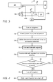
- Fig. 3 is a block diagram that schematically describes a fail-safe architecture 66 used during the ablation procedure described by Fig. 1 , according to an embodiment of the present invention.
- pump 24 is connected to an electromotive power source 59.
- Processor 46 can instruct, via a line 55, a relay device 57 to close or open a switch 47, and thereby switch pump 24 on and off, respectively.
- bubble detector 25 is wired parallel to pump 24 in a fail-safe power wiring scheme, where the detector is wired to power leads 44a and 44b of the irrigation pump. This fail-safe power wiring scheme ensures that bubble detector 25 is switched on whenever pump 24 receives operating power.
- bubble detector 25 While operating, bubble detector 25 sends fail-safe signals to processor 46 via line 35, for processor 46 to regularly verify that bubble detector 25 is properly operating. If processor 46 stops receiving the fail-safe signals, processor 46 directs relay 57, via a command line 55, to open switch 47 so as to turn off irrigation pump 24 and stop the flow of irrigation fluid. Examples of fail-safe signals are signals that give an effective temperature in the vicinity of bubble-detector 25 via a temperature sensor that works only if bubble detector 25 is active.
- bubble detector 25 is wired in parallel to another power source (not shown) that enables the bubble detector to be in a ready mode, so as to start operating within a given time delay after the irrigation pump is turned on.
- the other power source enables the bubble detector to operate regardless whether the irrigation pump is turned on or turned off.
- fail-safe architecture 66 shown in Fig. 3 was chosen purely for the sake of conceptual clarity. In practice, a fail-safe mechanism may be devised differently, or include additional elements (e.g., an uninterruptible power supply (UPS)), as would occur to a person having ordinary skills in the art.
- UPS uninterruptible power supply
- Fig. 4 is a flow chart of steps of an algorithm performed during the procedure described in Fig. 1 and with the fail-safe architecture 66 described in Fig.3 , according to an embodiment of the present invention.
- the algorithm carries out a process that begins with physician 14 first activating irrigation, including turning on pump 24, purging the irrigation channel and establish idle flow rate, in a turning on irrigation step 70.
- physician 14 inserts catheter 20, which is plugged into console 48 and coupled to irrigation pump 24, into a sheath 21 that has been pre-positioned in a lumen of patient 18, at a catheter insertion step 72.
- bubble detector 25 By being wired to irrigation pump 24 according to fail-safe architecture 66 and, bubble detector 25, which is located at a proximal portion of catheter 20, is automatically turned on and commences bubble detection, at a bubble detection step 74. However, in order to enable step 70, in one embodiment, bubble detector 25 turns off when the physician pushes a dedicated button for initiating a purge.
- Bubble detector 25 transmits fail-safe signals to indicate that the detector is properly carrying out bubble detection, at a fail-safe signaling step 76.
- the fail-safe signals are received, at a receiving fail-safe signals step 78, by processor 46 that controls irrigation module 24.
- Processor 46 continuously checks that the fail-safe signals are received, as required, during every prespecified time interval, in a fail-safe checking step 80. As long as the fail-safe signals are received the process returns to step 78 to continue monitoring. If processor 46 does not receive fail-safe signals within the prespecified duration, processor 46 then instructs turning off irrigation pump 24, at a fail-safe turning off step 82. At the same time, processor 46 issues an alert to the user, e.g., by the audiovisual methods described above, that irrigation is being turned off, at an alerting step 84.
Landscapes
- Health & Medical Sciences (AREA)
- Life Sciences & Earth Sciences (AREA)
- Engineering & Computer Science (AREA)
- Heart & Thoracic Surgery (AREA)
- Biomedical Technology (AREA)
- Animal Behavior & Ethology (AREA)
- General Health & Medical Sciences (AREA)
- Public Health (AREA)
- Veterinary Medicine (AREA)
- Surgery (AREA)
- Hematology (AREA)
- Anesthesiology (AREA)
- Nuclear Medicine, Radiotherapy & Molecular Imaging (AREA)
- Molecular Biology (AREA)
- Medical Informatics (AREA)
- Vascular Medicine (AREA)
- Plasma & Fusion (AREA)
- Physics & Mathematics (AREA)
- Otolaryngology (AREA)
- Cardiology (AREA)
- Pulmonology (AREA)
- Emergency Medicine (AREA)
- Infusion, Injection, And Reservoir Apparatuses (AREA)
- Surgical Instruments (AREA)
- Radiation-Therapy Devices (AREA)
- Endoscopes (AREA)
- Media Introduction/Drainage Providing Device (AREA)
Abstract
Description
- The present invention relates generally to invasive procedures, and specifically to monitoring of irrigation fluid used during invasive procedures.
- During some invasive medical procedures, tissue may be irrigated, and the irrigation fluid used may be monitored for the occurrence of bubbles. A number of bubble monitoring techniques were previously proposed in the patent literature. For example,
EP0053453 ,EP3076137 ,CN109789269 each describes a bubble detection system.U.S. Patent Application Publication 2019/054256 describes a method, including ejecting irrigation fluid from a distal end of a probe so as to irrigate tissue, and receiving, over a period of time, initial signals indicative of respective temperatures of the distal end, from a temperature sensor in the distal end. The method also includes formulating from the initial signals a temperature range between upper and lower temperature thresholds and, when a further signal from the temperature sensor, received subsequent to the period of time, is indicative of a further temperature above the upper temperature threshold, raising an alarm that a bubble is present in the irrigation fluid. All of the documents referenced are hereby incorporated by reference as if set forth herein with a copy in the Appendix. - An embodiment of the present invention provides a medical system including a probe, a processor, and a bubble detector. The probe is configured for insertion into a lumen of a patient and is coupled to an irrigation pump. The processor is configured to control delivery of irrigation fluid to the probe by turning on and controlling the irrigation pump. The bubble detector is coupled to a proximal portion of the probe. In response to the irrigation pump being turned on, the bubble detector is configured to automatically start detection of gas bubbles in the irrigated fluid, and transmit fail-safe signals indicating fail-safe bubble detection is operational. The processor is further configured to monitor the fail-safe signals and, in absence of fail-safe signals, to automatically disable delivery of the irrigation fluid.
- In some embodiments, the processor is further configured to alert a user that the delivery of the irrigation fluid is disabled.
- In some embodiments, the bubble detector is configured to transmit the fail-safe signals every prespecified time interval.
- In an embodiment, the processor is further configured to present to a user an option to override, for a given time duration, the automatic disabling of the delivery of the irrigation fluid.
- In another embodiment, the bubble detector is electrically wired to power leads of the irrigation pump, and is thus configured to start the detection in response to the irrigation pump being turned on.
- In some embodiments, the bubble detector is wired in parallel to an auxiliary power source that retains the bubble detector in a ready mode, so as to start operating within a given time delay after the irrigation pump is turned on.
- In some embodiments, the bubble detector is wired in parallel to an auxiliary power source that powers the bubble detector regardless of whether the irrigation pump is turned on or off.
- In an embodiment, the system further includes a drip detector, which is attached to a drip chamber of a saline bag that contains saline for use during purge. The drip detector is configured to send to the irrigation pump an indication that saline is dripping out of the bag, and if no indication is sent, a pump logic is configured to disable a purge button.
- In another embodiment, the pump logic is further configured, if no indication is sent from the drip detector, and an indication of decreasing level of saline in the drip chamber is received from a level indicator attached to a drip chamber, to terminate any ablation currently occurring and reduce the flow rate to an idle flow.
- There is additionally provided, in accordance with an embodiment of the present invention, a method including inserting a probe into a lumen of a patient, wherein the probe is coupled to an irrigation pump. Delivery of irrigation fluid to the probe is controlled by turning on and controlling the irrigation pump. In response to the irrigation pump being turned on, a bubble detector coupled to a proximal portion of the probe is controlled to automatically start detection of gas bubbles in the irrigated fluid, and to transmit fail-safe signals indicating fail-safe bubble detection is operational. The fail-safe signals are monitored and, in absence of fail-safe signals, delivery of the irrigation fluid is automatically disabled.
- The present disclosure will be more fully understood from the following detailed description of the embodiments thereof, taken together with the drawings, in which:
-
-
Fig. 1 is a schematic illustration of a catheter-based cardiac ablation system, according to an embodiment of the present invention; -
Fig. 2 is a schematic, pictorial illustration of a bubble detector coupled to a proximal end of a catheter handle, according to an embodiment of the present invention; -
Fig. 3 is a block diagram that schematically describes a fail-safe architecture used during the ablation procedure described byFig. 1 , according to an embodiment of the present invention; and -
Fig. 4 is a flow chart of steps of an algorithm performed during the procedure described inFig. 1 and with the fail-safe architecture described inFig.3 , according to an embodiment of the present invention. - There are a number of invasive procedures, such as an ablation procedure of an internal organ, where tissue undergoing the procedure is irrigated. In some cases, bubbles may be created in the irrigation fluid, which, if reaching the patient undergoing the procedure, may cause safety issues. Mechanisms for detecting bubbles at an irrigation pump used to pump the irrigation fluid may, as described below, fail to operate to detect the bubbles.
- Embodiments of the present invention that are described hereinafter provide fail-safe bubble detection systems comprising a bubble detector located at a proximal portion of a probe, such as a catheter, for insertion into a lumen of a patient. In the disclosed embodiment, "a proximal portion" means a portion of the probe which is outside the body of the patient. The probe is connected to a console that includes a processor-controlled irrigation pump for delivering irrigation fluid via the probe to irrigate tissue. The bubble detector has a fail-safe mechanism to ensure that the detector starts to detect possible gas bubbles in the streamed fluid in response to the irrigation pump being turned on.
- In some embodiments, a fail-safe wiring architecture is provided, in which the bubble detector is connected to the irrigation pump in a way such that, whenever the irrigation pump starts operating, the bubble detector automatically starts its operation as well. For example, the bubble detector may be wired to power leads located on the irrigation pump.
- In some embodiments, the bubble detector periodically transmits fail-safe signals while operating that indicate proper operation of the bubble detection system. The processor receives these fail-safe signals, and, in the absence of the fail-safe signals, is configured to turn off the irrigation pump and alert a user that irrigation is disabled. Alternatively, the processor first alerts the user, and only subsequently, within a prespecified duration, turns off the irrigation pump.
- In some embodiments, the processor is further configured to present to the user an option to override the automatic disabling of irrigation for a given time duration and allow the irrigation pump to continue operation before being automatically turned off. In an embodiment, the given duration may be further extended by the user.
- In some embodiments, a disclosed system for bubble detection is provided as an add-on to legacy systems, to overcome potentially hazardous medical scenarios in which irrigation is not sufficiently monitored for bubbles despite the system being equipped with a gas bubble detection sub-system.
- By locating an additional bubble detector with fail-safe mechanisms at a proximal portion of a probe, embodiments of the present invention may enhance patient safety during an invasive medical procedure that requires irrigation.
-
Fig. 1 is a schematic illustration of a catheter-basedcardiac ablation system 12, according to an embodiment of the present invention.System 12 is used by aphysician 14 to perform an invasive procedure, which, by way of example, is assumed to comprise radiofrequency (RF) ablation of a portion of amyocardium 16 of the heart of apatient 18. - In order to perform the ablation,
physician 14 uses acatheter handle 19 to insert acatheter 20 into asheath 21 that has been pre-positioned in a lumen of the patient. Sheath 21 is positioned so that adistal end 22 of the catheter may enter the heart of the patient, after exiting a distal end of the sheath, and then contact tissue of the heart. -
System 12 is controlled by asystem processor 46 andinterface circuitry 45. The processor can be programmed to perform at least one algorithm disclosed herein, the algorithm comprising steps described hereinbelow. The processor usesinterface circuitry 45 in order to perform the algorithm. -
Processor 46 is located in anoperating console 48 ofsystem 12.Console 48 comprisescontrols 49 which are used byphysician 14 to communicate withprocessor 46, which communicates with modules in amodule bank 50 to implement the procedure. The functions of modules inbank 50 are described below. - During the procedure performed by
physician 14,distal end 22 is supplied with irrigation fluid, typically heparinized normal saline solution, pumped by anirrigation pump 24. In someembodiments irrigation pump 24 comprises a peristaltic pump; alternatively, any other suitable irrigation fluid pump may be used. - An
irrigation module 56 ofprocessor 46 controls the rate of flow of the fluid frompump 24 tocatheter 20 viairrigation tubing 26.Irrigation module 56, under overall control ofprocessor 46, is typically configured to vary, as needed, the rate of fluid flow from a zero rate up to a predefined maximum rate. In one embodiment, oncedistal end 22 has been inserted intosheath 21,module 56 operatespump 24 to provide a minimal fluid flow rate of approximately 5 ml/min, which is increased by the module whenphysician 14 begins ablation. -
Irrigation pump 24 further comprises abubble detection sub-system 27, which operates while irrigation fluid is being provided to the catheter.Bubble detection sub-system 27 is disposed proximate an outlet ofirrigation pump 24. If a bubble is detected bysub-system 27, the flow of irrigation fluid is typically halted automatically byprocessor 46. In some cases, however,processor 46 initially raises an alarm tophysician 14 regarding the presence of bubbles in the irrigation fluid. The alarm may be an auditory non-verbal warning, such as a ring, or a recorded statement that is broadcast to the physician. Alternatively or additionally, the alarm may be a visual warning, such as a light that is switched on, or awarning notice 62 onscreen 60. -
Bubble detection sub-system 27 is normally disabled automatically during a "purge" phase (also termed a "splash") that is used to clear the irrigation tubes. The purge phase is usually not invoked whilecatheter 20 is inserted into a patient, however, such an event may occur accidentally. In this case,bubble detection sub-system 27 may have no way of detecting if a bubble enters the patient, with consequent problems. - Embodiments of the present invention provide an
extra bubble detector 25 to protect against events of irrigation operating with bubbles that are not prevented bydetection sub-system 27.Bubble detector 25 is connected to irrigation pump 24 via acable 37, in a fail-safe scheme ensuring that wheneverirrigation pump 24 is turned on,bubble detector 25 automatically starts operation to detect bubbles. However, in order to enable purge, in one embodiment,bubble detector 25 turns off when the physician pushes a dedicated purge button for initiating a purge. In another embodiment,bubble detector 25 is disconnected from the proximal portion of the catheter whenever a purge (e.g., a splash) is done, and only afterwards the physician connectsbubble detector 25 to the catheter. - For example, a fail-safe scheme may be realized by
bubble detector 25 being wired directly to the power leads ofirrigation pump 24. In some embodiments,bubble detector 25 may be connected to irrigation pump 24 via a cable. In other embodiments, a logic is used for the fail-safe scheme, withbubble detector 25 connected wirelessly to a control ofirrigation pump 24, to trigger the disabling ofpump 24. - In an optional embodiment, a drip detector or a level indicator is attached to a drip chamber of a saline bag that contains saline for use during purge. The drip detector sends to the irrigation pump an indication that saline is flowing out of the bag. If no indication is sent (as there is no saline flowing out of the bag) then a pump logic is configured to disable a purge button, described below, as the bag is empty.
- In an optional embodiment, the pump logic may be configured to identify when there are no drops, but the level indicator is decreasing (indicating that the saline is flowing but the bag is empty) . In this scenario, the pump logic can terminate any ablation currently occurring and reduce the flow rate to idle flow. This can allow the physician sufficient time to replace the empty IV bag before air is drawn into the tubing and the irrigation is forced to stop. The combination of both a drop counter and a level indicator can also allow for identification of occlusion, whether from a closed stopcock or an occluded device.
-
Bubble detector 25 is located (e.g., incorporated into or fitted over) a proximal portion ofcatheter 20 and is configured to transmit signals toprocessor 46 via acable 35 in response to bubbles detected in the irrigation fluid. The processor is configured to halt the irrigation flow if the extra bubble detector detects a bubble. Thus, even ifbubble detection sub-system 27 ofirrigation pump 24 is disabled, irrigation can be disabled when bubbles are detected. - In some embodiments,
bubble detector 25 is an add-on to legacy probes, for example by fitting the detector on an irrigation tube ofcatheter 20 and electrically connectingbubble detector 25 to console 48 to perform the steps described inFig. 4 . At the same time,processor 46, or another controller ofirrigation pump 24, is configured to perform steps responsively to signals frombubble detector 25, as also described below inFig. 4 . - In some embodiments,
bubble detector 25 functions in a fail-safe mode to ensure that irrigation is disabled unlessbubble sensor 25 actively indicates that it is operating. In an embodiment,bubble detector 25 is configured to transmit a fail-safe signal toprocessor 46 via acable 35 to indicate thatbubble detector 25 is active at a prespecified time interval (e.g., periodically).Processor 46 in configured to turn offirrigation pump 24 unless such a fail-safe signal is received within a prespecified duration. The prespecified duration and time-interval are adjustable. In another embodiment, theprocessor alerts physician 14, using one of the methods described above, before disabling irrigation. - In another embodiment,
bubble detector 25 includes a self-test, such as exist in the industry, to detect failure ofdetector 25, wherebybubble detector 25 is configured to stop sending the fail-safe signals viacable 35 in case such failure is self-detected. -
Processor 46 uses atemperature module 52 to analyze signals received from temperature sensors indistal end 22. From the analyzed signals,processor 46 determines temperatures of the distal end, and, in an embodiment, uses the sensed temperatures in a bubble-detection algorithm described in the aforementionedU.S. Patent Application Publication 2019/054256 filed August 15, 2017 , entitled "Detection of Bubbles in Irrigation Fluid," which is assigned to the assignee of the present patent application and whose disclosure is incorporated herein by reference. -
Module bank 50 also comprises anablation module 54, which enablesprocessor 46 to inject RF current via selected electrodes of distal end 22 (described below), and returning electrodes on the skin of the patient (not shown in the diagram), intomyocardium 16, in order to ablate regions of the myocardium which are in contact with the selected electrodes. The ablation module also enables the processor to set parameters of the injected current, such as its frequency, the power dissipated, and the duration of the injection. - In order to operate
system 12,module bank 50 typically comprises modules other than those described above, such as a force module enabling the processor to measure a force on the distal end, and an electrocardiogram (ECG) module enabling the processor to acquire electro-potentials frommyocardium 16 via electrodes in the distal end. For simplicity, other such modules are not illustrated inFig. 1 . All modules may comprise hardware as well as software elements. - The software for
processor 46 and the modules ofmodule bank 50 may be downloaded to the processor in electronic form, over a network, for example. Alternatively or additionally, the software may be provided on non-transitory tangible media, such as optical, magnetic, or electronic storage media. The processor, and typically the modules, comprise memory used to store the downloaded software, as well as to store data generated bysystem 12. -
Processor 46 may present results of the procedure performed byphysician 14, as well as results of the algorithm described below with reference toFig. 4 , on adisplay screen 60. -
Fig. 2 is a schematic, pictorial illustration of abubble detector 125 coupled to a proximal end of acatheter handle 19, according to an embodiment of the present invention. In this embodiment,physician 14 can readily disconnectbubble detector 125 from the proximal portion of the catheter whenever a purge (e.g., a splash) is done, and only afterwardsphysician 14 reconnectsbubble detector 125 to handle 19 to provide the disclosed fail-safe configuration. -
Fig. 3 is a block diagram that schematically describes a fail-safe architecture 66 used during the ablation procedure described byFig. 1 , according to an embodiment of the present invention. As seen, pump 24 is connected to anelectromotive power source 59.Processor 46 can instruct, via aline 55, arelay device 57 to close or open aswitch 47, and thereby switchpump 24 on and off, respectively. InFig. 3 ,bubble detector 25 is wired parallel to pump 24 in a fail-safe power wiring scheme, where the detector is wired to power leads 44a and 44b of the irrigation pump. This fail-safe power wiring scheme ensures thatbubble detector 25 is switched on wheneverpump 24 receives operating power. - While operating,
bubble detector 25 sends fail-safe signals toprocessor 46 vialine 35, forprocessor 46 to regularly verify thatbubble detector 25 is properly operating. Ifprocessor 46 stops receiving the fail-safe signals,processor 46 directsrelay 57, via acommand line 55, to openswitch 47 so as to turn offirrigation pump 24 and stop the flow of irrigation fluid. Examples of fail-safe signals are signals that give an effective temperature in the vicinity of bubble-detector 25 via a temperature sensor that works only ifbubble detector 25 is active. - In an optional embodiment,
bubble detector 25 is wired in parallel to another power source (not shown) that enables the bubble detector to be in a ready mode, so as to start operating within a given time delay after the irrigation pump is turned on. In another optional embodiment, the other power source enables the bubble detector to operate regardless whether the irrigation pump is turned on or turned off. - The example of the fail-
safe architecture 66 shown inFig. 3 was chosen purely for the sake of conceptual clarity. In practice, a fail-safe mechanism may be devised differently, or include additional elements (e.g., an uninterruptible power supply (UPS)), as would occur to a person having ordinary skills in the art. -
Fig. 4 is a flow chart of steps of an algorithm performed during the procedure described inFig. 1 and with the fail-safe architecture 66 described inFig.3 , according to an embodiment of the present invention. - The algorithm, according to the presented embodiment, carries out a process that begins with
physician 14 first activating irrigation, including turning onpump 24, purging the irrigation channel and establish idle flow rate, in a turning on irrigation step 70. Next,physician 14inserts catheter 20, which is plugged intoconsole 48 and coupled toirrigation pump 24, into asheath 21 that has been pre-positioned in a lumen ofpatient 18, at acatheter insertion step 72. - By being wired to irrigation pump 24 according to fail-
safe architecture 66 and,bubble detector 25, which is located at a proximal portion ofcatheter 20, is automatically turned on and commences bubble detection, at abubble detection step 74. However, in order to enable step 70, in one embodiment,bubble detector 25 turns off when the physician pushes a dedicated button for initiating a purge. -
Bubble detector 25 transmits fail-safe signals to indicate that the detector is properly carrying out bubble detection, at a fail-safe signaling step 76. - The fail-safe signals are received, at a receiving fail-safe signals step 78, by
processor 46 that controlsirrigation module 24. -
Processor 46 continuously checks that the fail-safe signals are received, as required, during every prespecified time interval, in a fail-safe checking step 80. As long as the fail-safe signals are received the process returns to step 78 to continue monitoring. Ifprocessor 46 does not receive fail-safe signals within the prespecified duration,processor 46 then instructs turning offirrigation pump 24, at a fail-safe turning offstep 82. At the same time,processor 46 issues an alert to the user, e.g., by the audiovisual methods described above, that irrigation is being turned off, at an alertingstep 84. - Although the embodiments described herein mainly address cardiac applications, the methods and systems described herein can also be used in other clinical applications, such as in any invasive medical procedures that require flowing liquid into a body of a patient during procedure.
- It will be appreciated that the embodiments described above are cited by way of example, and that the present invention is not limited to what has been particularly shown and described hereinabove. Rather, the scope of the present invention includes both combinations and subcombinations of the various features described hereinabove, as well as variations and modifications thereof which would occur to persons skilled in the art upon reading the foregoing description and which are not disclosed in the prior art.
Claims (15)
- A system, comprising:a probe for insertion into a lumen of a patient, wherein the probe is coupled to an irrigation pump;a bubble detection sub-system disposed proximate an outlet of the irrigation pump;a processor, which is configured to control delivery of irrigation fluid to the probe by turning on and controlling the irrigation pump;a bubble detector coupled to a proximal portion of the probe, wherein, in response to the irrigation pump being turned on, the bubble detector is configured to:automatically start detection of gas bubbles in the irrigated fluid; andtransmit fail-safe signals indicating fail-safe bubble detection is operational; andwherein the processor is further configured to monitor the fail-safe signals and, in absence of fail-safe signals, to automatically disable delivery of the irrigation fluid.
- A system, comprising:a probe for insertion into a lumen of a patient, wherein the probe is coupled to an irrigation pump;a processor, which is configured to control delivery of irrigation fluid to the probe by turning on and controlling the irrigation pump;a bubble detector coupled to a proximal portion of the probe, wherein, in response to the irrigation pump being turned on, the bubble detector is configured to:automatically start detection of gas bubbles in the irrigated fluid; andtransmit signals indicating bubble detection is operational; andwherein the processor is further configured to monitor the signals and, in absence of signals, to automatically disable delivery of the irrigation fluid.
- The system according to claim 2, further comprising a bubble detection system disposed proximate an outlet of the irrigation pump.
- The system according to claim 1, wherein the processor is further configured to alert a user that the delivery of the irrigation fluid is disabled.
- The system according to claim 1, wherein the bubble detector is configured to transmit the fail-safe signals every prespecified time interval.
- The system according to claim 1, wherein the processor is further configured to present to a user an option to override, for a given time duration, the automatic disabling of the delivery of the irrigation fluid.
- The system according to claim 1, wherein the bubble detector is electrically wired to power leads of the irrigation pump, and is thus configured to start the detection in response to the irrigation pump being turned on.
- The system according to claim 1, wherein the bubble detector is wired in parallel to an auxiliary power source that retains the bubble detector in a ready mode, so as to start operating within a given time delay after the irrigation pump is turned on.
- The system according to claim 1, wherein the bubble detector is wired in parallel to an auxiliary power source that powers the bubble detector regardless of whether the irrigation pump is turned on or off.
- The system according to claim 1, and comprising a drip detector, which is attached to a drip chamber of a saline bag that contains saline for use during purge, wherein the drip detector is configured to send to the irrigation pump an indication that saline is dripping out of the bag, and wherein if no indication is sent, a pump logic is configured to disable a purge button.
- The system according to claim 10, wherein the pump logic is further configured, if no indication is sent from the drip detector, and an indication of decreasing level of saline in the drip chamber is received from a level indicator attached to a drip chamber, to terminate any ablation currently occurring and reduce the flow rate to an idle flow.
- A method, comprising:inserting a probe into a lumen of a patient, wherein the probe is coupled to an irrigation pump;controlling delivery of irrigation fluid to the probe by turning on and controlling the irrigation pump;in response to the irrigation pump being turned on, controlling a bubble detector coupled to a proximal portion of the probe to automatically start detection of gas bubbles in the irrigated fluid, and to transmit fail-safe signals indicating fail-safe bubble detection is operational; andmonitoring the fail-safe signals and, in absence of fail-safe signals, automatically disabling delivery of the irrigation fluid.
- The method according to claim 12, and comprising alerting a user that the delivery of the irrigation fluid is disabled.
- The method according to claim 12, wherein transmitting the fail-safe signals comprises transmitting the fail-safe signals every prespecified time interval.
- The method according to claim 12, and comprising presenting to a user an option to override, for a given time duration, the automatic disabling of the delivery of the irrigation fluid.
Applications Claiming Priority (1)
| Application Number | Priority Date | Filing Date | Title |
|---|---|---|---|
| US16/526,764 US11737821B2 (en) | 2019-07-30 | 2019-07-30 | Bubble detector on proximal end of catheter with fail-safe mechanism |
Publications (2)
| Publication Number | Publication Date |
|---|---|
| EP3771475A1 true EP3771475A1 (en) | 2021-02-03 |
| EP3771475B1 EP3771475B1 (en) | 2022-09-28 |
Family
ID=71846306
Family Applications (1)
| Application Number | Title | Priority Date | Filing Date |
|---|---|---|---|
| EP20188421.0A Active EP3771475B1 (en) | 2019-07-30 | 2020-07-29 | Bubble detector on proximal end of catheter with fail-safe mechanism |
Country Status (5)
| Country | Link |
|---|---|
| US (1) | US11737821B2 (en) |
| EP (1) | EP3771475B1 (en) |
| JP (1) | JP7570841B2 (en) |
| CN (1) | CN112295033B (en) |
| IL (1) | IL275976B2 (en) |
Families Citing this family (19)
| Publication number | Priority date | Publication date | Assignee | Title |
|---|---|---|---|---|
| US11567037B2 (en) * | 2020-12-14 | 2023-01-31 | Honeywell International Inc. | Sensors, methods, and computer program products for fluid flow determinations |
| JP7677398B2 (en) | 2021-02-17 | 2025-05-15 | 日本電気株式会社 | Wireless terminal, Edge Enabler Server (EES), and methods therefor |
| US12447317B2 (en) | 2022-08-01 | 2025-10-21 | Imperative Care, Inc. | Method of priming concentrically stacked interventional devices |
| US12440289B2 (en) | 2022-08-01 | 2025-10-14 | Imperative Care, Inc. | Method of priming an interventional device assembly |
| US12446979B2 (en) | 2022-08-01 | 2025-10-21 | Imperative Care, Inc. | Method of performing a multi catheter robotic neurovascular procedure |
| US12564414B2 (en) | 2022-08-01 | 2026-03-03 | Imperative Care, Inc. | Method of supra-aortic access for a neurovascular procedure |
| US12558175B2 (en) | 2021-08-12 | 2026-02-24 | Imperative Care, Inc. | Multi catheter method of performing a robotic neurovascular procedure |
| US12419703B2 (en) | 2022-08-01 | 2025-09-23 | Imperative Care, Inc. | Robotic drive system for achieving supra-aortic access |
| US12564458B2 (en) | 2022-08-01 | 2026-03-03 | Imperative Care, Inc. | Method of robotically driving a multi catheter assembly above the aortic arch |
| CN116999640B (en) * | 2022-04-27 | 2026-04-21 | 四川锦江电子医疗器械科技股份有限公司 | A method for eliminating air bubble interference in a filling pump and the filling pump |
| US20240041480A1 (en) | 2022-08-02 | 2024-02-08 | Imperative Care, Inc. | Multi catheter system with integrated fluidics management |
| US11935389B2 (en) * | 2022-08-10 | 2024-03-19 | Honeywell International Inc. | Methods and apparatuses for monitoring intravenous fluid bags |
| CN120529877A (en) | 2022-12-01 | 2025-08-22 | 因普瑞缇夫护理公司 | Anti-buckling device for robotic catheter drive system |
| CN120529878A (en) | 2022-12-01 | 2025-08-22 | 因普瑞缇夫护理公司 | Telescopic drive platform and usage method |
| JP2026500622A (en) | 2022-12-01 | 2026-01-08 | インペラティブ ケア インコーポレイテッド | Controller for a robotic catheter drive system |
| WO2024238831A2 (en) | 2023-05-17 | 2024-11-21 | Imperative Care, Inc. | Fluidics control system for multi catheter stack |
| WO2024249670A2 (en) | 2023-05-31 | 2024-12-05 | Imperative Care, Inc. | Magnetic coupling through a sterile field barrier |
| USD1119865S1 (en) | 2023-11-30 | 2026-03-24 | Imperative Care, Inc. | Controller |
| CN117679631A (en) * | 2023-12-29 | 2024-03-12 | 上海炫脉医疗科技有限公司 | Ventricular assist systems and methods for detecting ventricular assist system cleaning fluid bubbles |
Citations (9)
| Publication number | Priority date | Publication date | Assignee | Title |
|---|---|---|---|---|
| EP0053453A1 (en) | 1980-12-03 | 1982-06-09 | Baxter Travenol Laboratories, Inc. | Ultrasonic bubble detector |
| US5053747A (en) * | 1989-09-05 | 1991-10-01 | Pacesetter Infusion, Inc. | Ultrasonic air-in-line detector self-test technique |
| US20080098798A1 (en) * | 2006-10-24 | 2008-05-01 | Riley Timothy A | Method for making and using an air bubble detector |
| US20140243821A1 (en) * | 2011-09-30 | 2014-08-28 | Covidien Lp | Energy delivery device and methods of use |
| EP3076137A1 (en) | 2015-11-13 | 2016-10-05 | Sensirion AG | Flow sensor for determining an air bubble, particularly in a catheter, and corresponding method |
| US20190054276A1 (en) * | 2014-01-17 | 2019-02-21 | Acutus Medical, Inc. | Gas-elimination patient access device |
| US20190054256A1 (en) | 2017-08-15 | 2019-02-21 | Biosense Webster (Israel) Ltd. | Detection of bubbles in irrigation fluid |
| CN208611483U (en) * | 2017-07-26 | 2019-03-19 | 深圳市好克医疗仪器股份有限公司 | A kind of infusion pump systems with the real-time self-checking function of bubble circuit |
| CN109789269A (en) | 2016-09-29 | 2019-05-21 | 皇家飞利浦有限公司 | The medical supply with thermal type mass flow sensor for bubble detection |
Family Cites Families (10)
| Publication number | Priority date | Publication date | Assignee | Title |
|---|---|---|---|---|
| DE3303102A1 (en) * | 1983-01-31 | 1984-08-02 | Siemens AG, 1000 Berlin und 8000 München | FLOW RATE CONTROL ARRANGEMENT |
| US4897184A (en) * | 1986-10-31 | 1990-01-30 | Cobe Laboratories, Inc. | Fluid flow apparatus control and monitoring |
| US5868710A (en) | 1996-11-22 | 1999-02-09 | Liebel Flarsheim Company | Medical fluid injector |
| US6986736B2 (en) * | 2002-12-23 | 2006-01-17 | Advanced Sterilization Products | Automated endoscope reprocessor connection integrity testing |
| JP2010051720A (en) | 2008-08-29 | 2010-03-11 | Jms Co Ltd | Transfusion device |
| US9375273B2 (en) * | 2009-09-18 | 2016-06-28 | Covidien Lp | System and method for checking high power microwave ablation system status on startup |
| WO2013162883A1 (en) * | 2012-04-26 | 2013-10-31 | Medtronic Ablation Frontiers Llc | Detection of microbubble formation during an ablation procedure |
| US9364285B2 (en) * | 2014-04-01 | 2016-06-14 | Biosense Webster (Israel) Ltd. | Sealed two-way magnetic manifold |
| CN106137379A (en) * | 2015-03-26 | 2016-11-23 | 四川锦江电子科技有限公司 | Charge pump, the control method of charge pump and device |
| US9889244B2 (en) * | 2015-12-17 | 2018-02-13 | Fresenius Medical Care Holdings, Inc. | System and method for controlling venous air recovery in a portable dialysis system |
-
2019
- 2019-07-30 US US16/526,764 patent/US11737821B2/en active Active
-
2020
- 2020-07-10 IL IL275976A patent/IL275976B2/en unknown
- 2020-07-29 EP EP20188421.0A patent/EP3771475B1/en active Active
- 2020-07-29 JP JP2020128027A patent/JP7570841B2/en active Active
- 2020-07-30 CN CN202010754551.2A patent/CN112295033B/en active Active
Patent Citations (9)
| Publication number | Priority date | Publication date | Assignee | Title |
|---|---|---|---|---|
| EP0053453A1 (en) | 1980-12-03 | 1982-06-09 | Baxter Travenol Laboratories, Inc. | Ultrasonic bubble detector |
| US5053747A (en) * | 1989-09-05 | 1991-10-01 | Pacesetter Infusion, Inc. | Ultrasonic air-in-line detector self-test technique |
| US20080098798A1 (en) * | 2006-10-24 | 2008-05-01 | Riley Timothy A | Method for making and using an air bubble detector |
| US20140243821A1 (en) * | 2011-09-30 | 2014-08-28 | Covidien Lp | Energy delivery device and methods of use |
| US20190054276A1 (en) * | 2014-01-17 | 2019-02-21 | Acutus Medical, Inc. | Gas-elimination patient access device |
| EP3076137A1 (en) | 2015-11-13 | 2016-10-05 | Sensirion AG | Flow sensor for determining an air bubble, particularly in a catheter, and corresponding method |
| CN109789269A (en) | 2016-09-29 | 2019-05-21 | 皇家飞利浦有限公司 | The medical supply with thermal type mass flow sensor for bubble detection |
| CN208611483U (en) * | 2017-07-26 | 2019-03-19 | 深圳市好克医疗仪器股份有限公司 | A kind of infusion pump systems with the real-time self-checking function of bubble circuit |
| US20190054256A1 (en) | 2017-08-15 | 2019-02-21 | Biosense Webster (Israel) Ltd. | Detection of bubbles in irrigation fluid |
Also Published As
| Publication number | Publication date |
|---|---|
| US11737821B2 (en) | 2023-08-29 |
| CN112295033B (en) | 2024-06-04 |
| US20210030465A1 (en) | 2021-02-04 |
| IL275976B2 (en) | 2023-07-01 |
| EP3771475B1 (en) | 2022-09-28 |
| CN112295033A (en) | 2021-02-02 |
| IL275976B1 (en) | 2023-03-01 |
| IL275976A (en) | 2021-01-31 |
| JP2021023808A (en) | 2021-02-22 |
| JP7570841B2 (en) | 2024-10-22 |
Similar Documents
| Publication | Publication Date | Title |
|---|---|---|
| US11737821B2 (en) | Bubble detector on proximal end of catheter with fail-safe mechanism | |
| US6468268B1 (en) | Cryogenic catheter system | |
| US5908402A (en) | Method and apparatus for detecting tube occlusion in argon electrosurgery system | |
| JP4780492B2 (en) | Separation detection method of embolism device | |
| US4743228A (en) | Fluid flow monitoring method and system | |
| EP3932350B1 (en) | Impedance controlled rf transseptal perforation | |
| CN114746037B (en) | Active pressure control and fault monitoring methods | |
| US20130255390A1 (en) | High pressure sensor for use with a fluid delivery system | |
| EP3272377B1 (en) | Infusion state detection system | |
| JP2020521559A (en) | Injector status logic with hemodynamic monitoring | |
| CN115176318A (en) | Adaptive pressure control filter for fluid management systems | |
| EP2939629B1 (en) | Aparatus for occluding a vessel by rf embolization | |
| AU2018211322A1 (en) | Detection of bubbles in irrigation fluid | |
| CA2547953C (en) | Cryogenic catheter system | |
| KR20160135175A (en) | Alarm device, extracorporeal circulation device, and alarm-device control method | |
| WO2005084139A2 (en) | Sting judgment device | |
| KR102545496B1 (en) | Fluid draining device having pressure sensor | |
| EP4186445A1 (en) | Release apparatus, release system, release method, and treatment apparatus | |
| CN110432975A (en) | An electrophysiological catheter with tactile feedback |
Legal Events
| Date | Code | Title | Description |
|---|---|---|---|
| PUAI | Public reference made under article 153(3) epc to a published international application that has entered the european phase |
Free format text: ORIGINAL CODE: 0009012 |
|
| STAA | Information on the status of an ep patent application or granted ep patent |
Free format text: STATUS: THE APPLICATION HAS BEEN PUBLISHED |
|
| STAA | Information on the status of an ep patent application or granted ep patent |
Free format text: STATUS: REQUEST FOR EXAMINATION WAS MADE |
|
| AK | Designated contracting states |
Kind code of ref document: A1 Designated state(s): AL AT BE BG CH CY CZ DE DK EE ES FI FR GB GR HR HU IE IS IT LI LT LU LV MC MK MT NL NO PL PT RO RS SE SI SK SM TR |
|
| AX | Request for extension of the european patent |
Extension state: BA ME |
|
| 17P | Request for examination filed |
Effective date: 20210111 |
|
| RBV | Designated contracting states (corrected) |
Designated state(s): AL AT BE BG CH CY CZ DE DK EE ES FI FR GB GR HR HU IE IS IT LI LT LU LV MC MK MT NL NO PL PT RO RS SE SI SK SM TR |
|
| GRAP | Despatch of communication of intention to grant a patent |
Free format text: ORIGINAL CODE: EPIDOSNIGR1 |
|
| STAA | Information on the status of an ep patent application or granted ep patent |
Free format text: STATUS: GRANT OF PATENT IS INTENDED |
|
| INTG | Intention to grant announced |
Effective date: 20220601 |
|
| RAP3 | Party data changed (applicant data changed or rights of an application transferred) |
Owner name: BIOSENSE WEBSTER (ISRAEL) LTD. |
|
| GRAS | Grant fee paid |
Free format text: ORIGINAL CODE: EPIDOSNIGR3 |
|
| GRAA | (expected) grant |
Free format text: ORIGINAL CODE: 0009210 |
|
| STAA | Information on the status of an ep patent application or granted ep patent |
Free format text: STATUS: THE PATENT HAS BEEN GRANTED |
|
| AK | Designated contracting states |
Kind code of ref document: B1 Designated state(s): AL AT BE BG CH CY CZ DE DK EE ES FI FR GB GR HR HU IE IS IT LI LT LU LV MC MK MT NL NO PL PT RO RS SE SI SK SM TR |
|
| REG | Reference to a national code |
Ref country code: GB Ref legal event code: FG4D |
|
| REG | Reference to a national code |
Ref country code: CH Ref legal event code: EP |
|
| REG | Reference to a national code |
Ref country code: DE Ref legal event code: R096 Ref document number: 602020005319 Country of ref document: DE |
|
| REG | Reference to a national code |
Ref country code: AT Ref legal event code: REF Ref document number: 1520830 Country of ref document: AT Kind code of ref document: T Effective date: 20221015 |
|
| REG | Reference to a national code |
Ref country code: IE Ref legal event code: FG4D |
|
| REG | Reference to a national code |
Ref country code: NL Ref legal event code: FP |
|
| REG | Reference to a national code |
Ref country code: LT Ref legal event code: MG9D |
|
| PG25 | Lapsed in a contracting state [announced via postgrant information from national office to epo] |
Ref country code: SE Free format text: LAPSE BECAUSE OF FAILURE TO SUBMIT A TRANSLATION OF THE DESCRIPTION OR TO PAY THE FEE WITHIN THE PRESCRIBED TIME-LIMIT Effective date: 20220928 Ref country code: RS Free format text: LAPSE BECAUSE OF FAILURE TO SUBMIT A TRANSLATION OF THE DESCRIPTION OR TO PAY THE FEE WITHIN THE PRESCRIBED TIME-LIMIT Effective date: 20220928 Ref country code: NO Free format text: LAPSE BECAUSE OF FAILURE TO SUBMIT A TRANSLATION OF THE DESCRIPTION OR TO PAY THE FEE WITHIN THE PRESCRIBED TIME-LIMIT Effective date: 20221228 Ref country code: LV Free format text: LAPSE BECAUSE OF FAILURE TO SUBMIT A TRANSLATION OF THE DESCRIPTION OR TO PAY THE FEE WITHIN THE PRESCRIBED TIME-LIMIT Effective date: 20220928 Ref country code: LT Free format text: LAPSE BECAUSE OF FAILURE TO SUBMIT A TRANSLATION OF THE DESCRIPTION OR TO PAY THE FEE WITHIN THE PRESCRIBED TIME-LIMIT Effective date: 20220928 Ref country code: FI Free format text: LAPSE BECAUSE OF FAILURE TO SUBMIT A TRANSLATION OF THE DESCRIPTION OR TO PAY THE FEE WITHIN THE PRESCRIBED TIME-LIMIT Effective date: 20220928 |
|
| REG | Reference to a national code |
Ref country code: AT Ref legal event code: MK05 Ref document number: 1520830 Country of ref document: AT Kind code of ref document: T Effective date: 20220928 |
|
| PG25 | Lapsed in a contracting state [announced via postgrant information from national office to epo] |
Ref country code: HR Free format text: LAPSE BECAUSE OF FAILURE TO SUBMIT A TRANSLATION OF THE DESCRIPTION OR TO PAY THE FEE WITHIN THE PRESCRIBED TIME-LIMIT Effective date: 20220928 Ref country code: GR Free format text: LAPSE BECAUSE OF FAILURE TO SUBMIT A TRANSLATION OF THE DESCRIPTION OR TO PAY THE FEE WITHIN THE PRESCRIBED TIME-LIMIT Effective date: 20221229 |
|
| PG25 | Lapsed in a contracting state [announced via postgrant information from national office to epo] |
Ref country code: SM Free format text: LAPSE BECAUSE OF FAILURE TO SUBMIT A TRANSLATION OF THE DESCRIPTION OR TO PAY THE FEE WITHIN THE PRESCRIBED TIME-LIMIT Effective date: 20220928 Ref country code: RO Free format text: LAPSE BECAUSE OF FAILURE TO SUBMIT A TRANSLATION OF THE DESCRIPTION OR TO PAY THE FEE WITHIN THE PRESCRIBED TIME-LIMIT Effective date: 20220928 Ref country code: PT Free format text: LAPSE BECAUSE OF FAILURE TO SUBMIT A TRANSLATION OF THE DESCRIPTION OR TO PAY THE FEE WITHIN THE PRESCRIBED TIME-LIMIT Effective date: 20230130 Ref country code: ES Free format text: LAPSE BECAUSE OF FAILURE TO SUBMIT A TRANSLATION OF THE DESCRIPTION OR TO PAY THE FEE WITHIN THE PRESCRIBED TIME-LIMIT Effective date: 20220928 Ref country code: CZ Free format text: LAPSE BECAUSE OF FAILURE TO SUBMIT A TRANSLATION OF THE DESCRIPTION OR TO PAY THE FEE WITHIN THE PRESCRIBED TIME-LIMIT Effective date: 20220928 Ref country code: AT Free format text: LAPSE BECAUSE OF FAILURE TO SUBMIT A TRANSLATION OF THE DESCRIPTION OR TO PAY THE FEE WITHIN THE PRESCRIBED TIME-LIMIT Effective date: 20220928 |
|
| PG25 | Lapsed in a contracting state [announced via postgrant information from national office to epo] |
Ref country code: SK Free format text: LAPSE BECAUSE OF FAILURE TO SUBMIT A TRANSLATION OF THE DESCRIPTION OR TO PAY THE FEE WITHIN THE PRESCRIBED TIME-LIMIT Effective date: 20220928 Ref country code: PL Free format text: LAPSE BECAUSE OF FAILURE TO SUBMIT A TRANSLATION OF THE DESCRIPTION OR TO PAY THE FEE WITHIN THE PRESCRIBED TIME-LIMIT Effective date: 20220928 Ref country code: IS Free format text: LAPSE BECAUSE OF FAILURE TO SUBMIT A TRANSLATION OF THE DESCRIPTION OR TO PAY THE FEE WITHIN THE PRESCRIBED TIME-LIMIT Effective date: 20230128 Ref country code: EE Free format text: LAPSE BECAUSE OF FAILURE TO SUBMIT A TRANSLATION OF THE DESCRIPTION OR TO PAY THE FEE WITHIN THE PRESCRIBED TIME-LIMIT Effective date: 20220928 |
|
| REG | Reference to a national code |
Ref country code: DE Ref legal event code: R097 Ref document number: 602020005319 Country of ref document: DE |
|
| PG25 | Lapsed in a contracting state [announced via postgrant information from national office to epo] |
Ref country code: AL Free format text: LAPSE BECAUSE OF FAILURE TO SUBMIT A TRANSLATION OF THE DESCRIPTION OR TO PAY THE FEE WITHIN THE PRESCRIBED TIME-LIMIT Effective date: 20220928 |
|
| PG25 | Lapsed in a contracting state [announced via postgrant information from national office to epo] |
Ref country code: DK Free format text: LAPSE BECAUSE OF FAILURE TO SUBMIT A TRANSLATION OF THE DESCRIPTION OR TO PAY THE FEE WITHIN THE PRESCRIBED TIME-LIMIT Effective date: 20220928 |
|
| PLBE | No opposition filed within time limit |
Free format text: ORIGINAL CODE: 0009261 |
|
| STAA | Information on the status of an ep patent application or granted ep patent |
Free format text: STATUS: NO OPPOSITION FILED WITHIN TIME LIMIT |
|
| 26N | No opposition filed |
Effective date: 20230629 |
|
| PG25 | Lapsed in a contracting state [announced via postgrant information from national office to epo] |
Ref country code: SI Free format text: LAPSE BECAUSE OF FAILURE TO SUBMIT A TRANSLATION OF THE DESCRIPTION OR TO PAY THE FEE WITHIN THE PRESCRIBED TIME-LIMIT Effective date: 20220928 |
|
| PG25 | Lapsed in a contracting state [announced via postgrant information from national office to epo] |
Ref country code: MC Free format text: LAPSE BECAUSE OF FAILURE TO SUBMIT A TRANSLATION OF THE DESCRIPTION OR TO PAY THE FEE WITHIN THE PRESCRIBED TIME-LIMIT Effective date: 20220928 |
|
| PG25 | Lapsed in a contracting state [announced via postgrant information from national office to epo] |
Ref country code: MC Free format text: LAPSE BECAUSE OF FAILURE TO SUBMIT A TRANSLATION OF THE DESCRIPTION OR TO PAY THE FEE WITHIN THE PRESCRIBED TIME-LIMIT Effective date: 20220928 |
|
| REG | Reference to a national code |
Ref country code: CH Ref legal event code: PL |
|
| REG | Reference to a national code |
Ref country code: BE Ref legal event code: MM Effective date: 20230731 |
|
| PG25 | Lapsed in a contracting state [announced via postgrant information from national office to epo] |
Ref country code: LU Free format text: LAPSE BECAUSE OF NON-PAYMENT OF DUE FEES Effective date: 20230729 |
|
| PG25 | Lapsed in a contracting state [announced via postgrant information from national office to epo] |
Ref country code: LU Free format text: LAPSE BECAUSE OF NON-PAYMENT OF DUE FEES Effective date: 20230729 |
|
| REG | Reference to a national code |
Ref country code: IE Ref legal event code: MM4A |
|
| PG25 | Lapsed in a contracting state [announced via postgrant information from national office to epo] |
Ref country code: CH Free format text: LAPSE BECAUSE OF NON-PAYMENT OF DUE FEES Effective date: 20230731 |
|
| PG25 | Lapsed in a contracting state [announced via postgrant information from national office to epo] |
Ref country code: BE Free format text: LAPSE BECAUSE OF NON-PAYMENT OF DUE FEES Effective date: 20230731 |
|
| PG25 | Lapsed in a contracting state [announced via postgrant information from national office to epo] |
Ref country code: IE Free format text: LAPSE BECAUSE OF NON-PAYMENT OF DUE FEES Effective date: 20230729 |
|
| PG25 | Lapsed in a contracting state [announced via postgrant information from national office to epo] |
Ref country code: IE Free format text: LAPSE BECAUSE OF NON-PAYMENT OF DUE FEES Effective date: 20230729 |
|
| PG25 | Lapsed in a contracting state [announced via postgrant information from national office to epo] |
Ref country code: BG Free format text: LAPSE BECAUSE OF FAILURE TO SUBMIT A TRANSLATION OF THE DESCRIPTION OR TO PAY THE FEE WITHIN THE PRESCRIBED TIME-LIMIT Effective date: 20220928 |
|
| PG25 | Lapsed in a contracting state [announced via postgrant information from national office to epo] |
Ref country code: BG Free format text: LAPSE BECAUSE OF FAILURE TO SUBMIT A TRANSLATION OF THE DESCRIPTION OR TO PAY THE FEE WITHIN THE PRESCRIBED TIME-LIMIT Effective date: 20220928 |
|
| PGFP | Annual fee paid to national office [announced via postgrant information from national office to epo] |
Ref country code: GB Payment date: 20250605 Year of fee payment: 6 |
|
| PGFP | Annual fee paid to national office [announced via postgrant information from national office to epo] |
Ref country code: NL Payment date: 20250613 Year of fee payment: 6 |
|
| PGFP | Annual fee paid to national office [announced via postgrant information from national office to epo] |
Ref country code: FR Payment date: 20250610 Year of fee payment: 6 |
|
| PG25 | Lapsed in a contracting state [announced via postgrant information from national office to epo] |
Ref country code: CY Free format text: LAPSE BECAUSE OF FAILURE TO SUBMIT A TRANSLATION OF THE DESCRIPTION OR TO PAY THE FEE WITHIN THE PRESCRIBED TIME-LIMIT; INVALID AB INITIO Effective date: 20200729 |
|
| PG25 | Lapsed in a contracting state [announced via postgrant information from national office to epo] |
Ref country code: HU Free format text: LAPSE BECAUSE OF FAILURE TO SUBMIT A TRANSLATION OF THE DESCRIPTION OR TO PAY THE FEE WITHIN THE PRESCRIBED TIME-LIMIT; INVALID AB INITIO Effective date: 20200729 |
|
| PGFP | Annual fee paid to national office [announced via postgrant information from national office to epo] |
Ref country code: DE Payment date: 20250604 Year of fee payment: 6 |
|
| PGFP | Annual fee paid to national office [announced via postgrant information from national office to epo] |
Ref country code: IT Payment date: 20250623 Year of fee payment: 6 |
|
| PG25 | Lapsed in a contracting state [announced via postgrant information from national office to epo] |
Ref country code: TR Free format text: LAPSE BECAUSE OF FAILURE TO SUBMIT A TRANSLATION OF THE DESCRIPTION OR TO PAY THE FEE WITHIN THE PRESCRIBED TIME-LIMIT Effective date: 20220928 |