EP3771391A1 - Mobile robot - Google Patents
Mobile robot Download PDFInfo
- Publication number
- EP3771391A1 EP3771391A1 EP20188620.7A EP20188620A EP3771391A1 EP 3771391 A1 EP3771391 A1 EP 3771391A1 EP 20188620 A EP20188620 A EP 20188620A EP 3771391 A1 EP3771391 A1 EP 3771391A1
- Authority
- EP
- European Patent Office
- Prior art keywords
- bumper
- mobile robot
- module
- impact
- disposed
- Prior art date
- Legal status (The legal status is an assumption and is not a legal conclusion. Google has not performed a legal analysis and makes no representation as to the accuracy of the status listed.)
- Granted
Links
Images


Classifications
-
- A—HUMAN NECESSITIES
- A47—FURNITURE; DOMESTIC ARTICLES OR APPLIANCES; COFFEE MILLS; SPICE MILLS; SUCTION CLEANERS IN GENERAL
- A47L—DOMESTIC WASHING OR CLEANING; SUCTION CLEANERS IN GENERAL
- A47L9/00—Details or accessories of suction cleaners, e.g. mechanical means for controlling the suction or for effecting pulsating action; Storing devices specially adapted to suction cleaners or parts thereof; Carrying-vehicles specially adapted for suction cleaners
- A47L9/28—Installation of the electric equipment, e.g. adaptation or attachment to the suction cleaner; Controlling suction cleaners by electric means
-
- B—PERFORMING OPERATIONS; TRANSPORTING
- B25—HAND TOOLS; PORTABLE POWER-DRIVEN TOOLS; MANIPULATORS
- B25J—MANIPULATORS; CHAMBERS PROVIDED WITH MANIPULATION DEVICES
- B25J11/00—Manipulators not otherwise provided for
- B25J11/008—Manipulators for service tasks
- B25J11/0085—Cleaning
-
- B—PERFORMING OPERATIONS; TRANSPORTING
- B60—VEHICLES IN GENERAL
- B60R—VEHICLES, VEHICLE FITTINGS, OR VEHICLE PARTS, NOT OTHERWISE PROVIDED FOR
- B60R19/00—Wheel guards; Radiator guards, e.g. grilles; Obstruction removers; Fittings damping bouncing force in collisions
- B60R19/02—Bumpers, i.e. impact receiving or absorbing members for protecting vehicles or fending off blows from other vehicles or objects
- B60R19/42—Bumpers, i.e. impact receiving or absorbing members for protecting vehicles or fending off blows from other vehicles or objects extending primarily along the sides of, or completely encircling, a vehicle
-
- A—HUMAN NECESSITIES
- A47—FURNITURE; DOMESTIC ARTICLES OR APPLIANCES; COFFEE MILLS; SPICE MILLS; SUCTION CLEANERS IN GENERAL
- A47L—DOMESTIC WASHING OR CLEANING; SUCTION CLEANERS IN GENERAL
- A47L9/00—Details or accessories of suction cleaners, e.g. mechanical means for controlling the suction or for effecting pulsating action; Storing devices specially adapted to suction cleaners or parts thereof; Carrying-vehicles specially adapted for suction cleaners
- A47L9/009—Carrying-vehicles; Arrangements of trollies or wheels; Means for avoiding mechanical obstacles
-
- A—HUMAN NECESSITIES
- A47—FURNITURE; DOMESTIC ARTICLES OR APPLIANCES; COFFEE MILLS; SPICE MILLS; SUCTION CLEANERS IN GENERAL
- A47L—DOMESTIC WASHING OR CLEANING; SUCTION CLEANERS IN GENERAL
- A47L9/00—Details or accessories of suction cleaners, e.g. mechanical means for controlling the suction or for effecting pulsating action; Storing devices specially adapted to suction cleaners or parts thereof; Carrying-vehicles specially adapted for suction cleaners
- A47L9/28—Installation of the electric equipment, e.g. adaptation or attachment to the suction cleaner; Controlling suction cleaners by electric means
- A47L9/2836—Installation of the electric equipment, e.g. adaptation or attachment to the suction cleaner; Controlling suction cleaners by electric means characterised by the parts which are controlled
- A47L9/2852—Elements for displacement of the vacuum cleaner or the accessories therefor, e.g. wheels, casters or nozzles
-
- B—PERFORMING OPERATIONS; TRANSPORTING
- B25—HAND TOOLS; PORTABLE POWER-DRIVEN TOOLS; MANIPULATORS
- B25J—MANIPULATORS; CHAMBERS PROVIDED WITH MANIPULATION DEVICES
- B25J19/00—Accessories fitted to manipulators, e.g. for monitoring, for viewing; Safety devices combined with or specially adapted for use in connection with manipulators
- B25J19/0075—Means for protecting the manipulator from its environment or vice versa
-
- B—PERFORMING OPERATIONS; TRANSPORTING
- B25—HAND TOOLS; PORTABLE POWER-DRIVEN TOOLS; MANIPULATORS
- B25J—MANIPULATORS; CHAMBERS PROVIDED WITH MANIPULATION DEVICES
- B25J19/00—Accessories fitted to manipulators, e.g. for monitoring, for viewing; Safety devices combined with or specially adapted for use in connection with manipulators
- B25J19/0091—Shock absorbers
-
- B—PERFORMING OPERATIONS; TRANSPORTING
- B25—HAND TOOLS; PORTABLE POWER-DRIVEN TOOLS; MANIPULATORS
- B25J—MANIPULATORS; CHAMBERS PROVIDED WITH MANIPULATION DEVICES
- B25J19/00—Accessories fitted to manipulators, e.g. for monitoring, for viewing; Safety devices combined with or specially adapted for use in connection with manipulators
- B25J19/02—Sensing devices
-
- B—PERFORMING OPERATIONS; TRANSPORTING
- B60—VEHICLES IN GENERAL
- B60R—VEHICLES, VEHICLE FITTINGS, OR VEHICLE PARTS, NOT OTHERWISE PROVIDED FOR
- B60R19/00—Wheel guards; Radiator guards, e.g. grilles; Obstruction removers; Fittings damping bouncing force in collisions
- B60R19/02—Bumpers, i.e. impact receiving or absorbing members for protecting vehicles or fending off blows from other vehicles or objects
- B60R19/24—Arrangements for mounting bumpers on vehicles
- B60R19/26—Arrangements for mounting bumpers on vehicles comprising yieldable mounting means
- B60R19/28—Metallic springs
-
- A—HUMAN NECESSITIES
- A47—FURNITURE; DOMESTIC ARTICLES OR APPLIANCES; COFFEE MILLS; SPICE MILLS; SUCTION CLEANERS IN GENERAL
- A47L—DOMESTIC WASHING OR CLEANING; SUCTION CLEANERS IN GENERAL
- A47L2201/00—Robotic cleaning machines, i.e. with automatic control of the travelling movement or the cleaning operation
- A47L2201/04—Automatic control of the travelling movement; Automatic obstacle detection
Definitions
- the following description relates to a mobile robot, and more particularly to a mobile robot having a bumper which surrounds a body, and modules for sensing impact on the bumper and restoring the position of the bumper.
- Robots have been developed for industrial applications and used as part of factory automation systems. Recently, robot applications are further extended to the field of medical robots, robots for aerospace applications and the like, and even robots for home use are being developed. These robots include robots capable of autonomously moving.
- a typical example of mobile robots for home use is a robot cleaner, which is a device for cleaning a certain area by sucking dust or foreign materials while traveling in the area.
- the robot cleaner is mainly composed of a cleaning robot and a charging stand.
- the cleaning robot includes a rechargeable battery, and may move freely and autonomously using power from the battery.
- the cleaning robot performs cleaning by sucking foreign materials from the floor, and if necessary, the cleaning robot returns to the charging stand to recharge the battery.
- Korean Laid-open Patent Publication No. 10-2013-005513 relates to a bumper assembly of a mobile robot capable of accurately detecting not only a front impact but also a side impact when the mobile robot collides with an obstacle.
- the bumper assembly has drawbacks in that the bumper assembly of the mobile robot includes a guide member for guiding forward/rearward movement, restricts the movement of the bumper to a two-dimensional movement, and includes no device for guiding the bumper to a certain position, thereby failing to allow various movements of the bumper.
- Korean Laid-open Patent Publication No. 10-2006-0118903 relates to a bumper device of a robot cleaner which includes: a bumper installed to surround an outer circumference of a main body of the robot cleaner to absorb shock; a bumper housing which forms an exterior of the bumper and is made of a material for restraining expansion; an air tube which is inserted into the bumper housing so as to be expandable along an internal passage of the bumper housing; and a sensor for sensing expansion of the air tube. Accordingly, even if an impact is applied on any position including the front surface of the main body of the robot cleaner, the bumper device may absorb shock and sense collision, and may prevent waste of space and cost by reducing volume and weight. However, the bumper device has a problem in that the bumper device also restricts the movement of the bumper to a two-dimensional movement, and fails to provide a solution to a device for guiding the bumper to a certain position.
- a mobile robot including: a body which forms an exterior of the mobile robot; a bumper which is spaced apart from the body and surrounds at least a portion of an outer circumference of the body; a position restoring module, with one side being connected to the body and the other side being connected to the bumper, and having an elastic member; a bumper guide module, having a guide hole which is formed at one side of the bumper, and a protruding guider which moves inside the guide hole; and an impact sensing module disposed at one side of the body, and having a bar which is adjacent to the bumper and moves along with the bumper when impact is applied, and a detection sensor configured to detect movement of the bar.
- the guide hole may include: an origin point, at which the protruding guider is located when no impact is applied; a first part which extends leftward from the origin point; a second part which extends rightward from the origin point; and a third part which connects a left end of the first part and a right end of the second part.
- An angle formed between the first part and the second part may be an obtuse angle.
- the origin point may be located behind the left end of the first part or the right end of the second part.
- the guide hole may have a fan shape.
- the mobile robot may further include a separation prevention cap which is connected to a top of the protruding guider.
- the mobile robot may further include one or more protrusions, which protrude upward from the bumper, and one or more protrusions which protrude upward from the body.
- the position restoring module may further include a first protruding member, which protrudes upward from one side of the body, and a second protruding member which protrudes from one side of the bumper and is disposed behind the first protruding member; and the elastic member may connect the first protruding member and the second protruding member.
- the impact sensing module may include: a sensing module case disposed at one side of the body; a hinge disposed inside the sensing module case and having a rotation axis which is perpendicular to the floor; a first bar, one side of which is adjacent to an inner surface of the bumper and the other side of which is connected to the hinge; and a second bar, on one side of which a detection sensor for detecting movement is disposed, and the other side of which is connected to the hinge.
- the mobile robot has one or more of the following effects.
- the bumper may freely move within a predetermined range when an external force is applied, and may return to the origin point.
- the position restoring module is disposed diagonally, such that the same restoring force may be provided for different impulses of a side impact and a front impact.
- the front impact or the side impact may be detected, as well as a small external force.
- first,” “second,” “third,” etc. used in this disclosure, do not necessarily denote any order, importance, or hierarchy, but rather the terms are used to merely distinguish one element from another. For example, only a second element may be included without a first element.
- microp used herein may be made of various materials, such as fabric or paper, and may be intended for repetitive use by washing or for one-time use.
- Th present disclosure may be applied to a mobile robot which may be manually moved by a user, a robot cleaner which may autonomously move, and the like.
- a mobile robot which may be manually moved by a user
- a robot cleaner which may autonomously move, and the like.
- the following description will be given using a mobile robot as an example.
- a mobile robot 1 has a body 20 including a controller.
- the mobile robot 1 includes a mop module 40 configured to mop a floor while being in contact with the floor (surface to be cleaned).
- the mobile robot 1 includes a sweep module configured to collect foreign materials on the floor.
- the mop module 40 is disposed below the body 20 and supports the body 20.
- the sweep module 20 is disposed below the body 20 and supports the body 20. In the embodiment, the body 20 is supported by the mop module 40 and the sweep module.
- the body 20 forms an exterior of the mobile robot 1.
- the body 20 is disposed to connect the mop module 40 and the sweep module.
- the mop module 40 may form an exterior.
- the mop module 40 is disposed below the body 20 and at the rear of the sweep module.
- the mop module 40 provides a driving force for movement of the mobile robot 1.
- the mop module 40 is desirably disposed at the rear of the mobile robot 1.
- the mop module 40 includes at least one floor cloth 411 which wipes the floor while rotating.
- the mop module 40 includes at least one spin mop 41, which when viewed from the top, rotates clockwise or counterclockwise. The spin mop 41 is in contact with the floor.
- the mop module 40 includes a pair of spin mops 41a and 41b.
- the pair of spin mops 41a and 41b rotate clockwise or counter-clockwise when viewed from above, and mops the floor during the rotation.
- a spin mop which is located at the left side when viewed from the front in a traveling direction of the mobile robot 1, is defined as a left spin mop 41a, and a spin mop located at the right side is defined as a right spin mop 41b.
- Each of the left spin mop 41a and the right spin mop 41b rotates about a rotation axis.
- the rotation axis is disposed vertically.
- the left spin mop 41a and the right spin mop 41b may rotate independently of each other.
- Each of the left spin mop 41a and the right spin mop 41b includes the floor cloth 411, a rotary plate 412, and a spin shaft 414.
- Each of the left spin mop 41a and the right spin mop 41b includes a water accommodating part 413.
- the sweep module may form an exterior.
- the sweep module is disposed at the front of the mop module 40.
- the sweep module is desirably disposed at the front in a traveling direction of the mobile robot 1.
- the sweep module is spaced apart from the mop module 40.
- the sweep module is disposed at the front of the mop module 40 and is in contact with the floor.
- the sweep module collects foreign materials from the floor.
- the sweep module While being in contact with the floor, the sweep module collects foreign materials, located in front of the sweep module, into the inside while the mobile robot 1 moves.
- the sweep module is disposed below the body 20.
- the sweep module has a width from side to side which is smaller than a width from side to side of the mop module 40.
- the bumper 30 may surround at least a portion of an outer circumference of the body 20, may surround the entire outer circumference of the body 20, or may surround a top portion of the body 20.
- the bumper 30 includes a case 31, which forms an exterior of the mobile robot 1, and a base 32 which is disposed below the case 31.
- the case 31 forms a lateral surface and a top surface of the bumper 30.
- the base 32 forms a bottom surface of the bumper 30.
- the case 31 has a cylindrical shape with an open bottom surface.
- the overall shape of the case 31 is a circle.
- a radius of gyration during rotation may be minimized.
- the case 31 includes: a top wall 311 having a circular shape; and a side wall 312 which is integrally formed with the top wall 311 and extends downward from the edge of the top wall 311.
- the side wall 312 is partially open.
- An open portion of the side wall 312 is defined as a water tank insertion hole 313, through which a water tank 81 is detachably installed.
- the water tank insertion hole 313 is formed at the rear in a traveling direction of the mobile robot 1. As the water tank 81 is inserted through the water tank insertion hole 313, the water tank insertion hole 313 is desirably disposed adjacent to the mop module 40.
- the mop module 40 is connected to the base 32, and the sweep module 80 is connected to the base 32.
- a controller Co and a battery Bt are provided in an internal space formed by the case 31 and the base 32. Further, a mop driving part is disposed in the body 20.
- the water supply module 80 is disposed at the body 20.
- the base 32 includes: a base body 321 which covers the open bottom surface of the case 31; a base guard 322 which is formed along an outer edge of the base body 321 and protrudes downward from the edge of the base body 321; and an insertion hole 323 which is vertically formed through the base body 321, and into which the sweep module 2000 is detachably inserted.
- FIGS. 1 to 8 a bumper guide structure will be described with reference to FIGS. 1 to 8 .
- the bumper guide structure includes: a position restoring module 60 which provides a restoring force toward a position before impact when the impact is applied to the mobile robot; a bumper guide module 50 which guides the mobile robot to the position before impact while the position is restored; and an impact sensing module 70 which senses the impact applied to the mobile robot.
- the bumper guide module 50 will be described below with reference to FIGS. 2 to 5 .
- the bumper guide module 50 is a device which allows the bumper 30 to move within a predetermined range when an impact is applied, and which guides the bumper 30 to a position before impact when the bumper 30 moves.
- the bumper guide module 50 has a guide hole 51 formed at the bumper 30 or the body 20, and a protruding guider 53 which is inserted into the guide hole and moves inside the guide hole.
- the shape of the guide hole 511 will be described below with reference to FIGS. 2 and 5 .
- the guide hole 51 is formed at the bumper 30 or the body 20. As illustrated in FIGS. 2 and 5 , the guide hole 51 may be formed through the bumper 30, and may be formed at the body 20 within a range which may be easily modified by those skilled in the art.
- the guide hole 51 may be horizontal to the ground as illustrated in FIGS. 2 and 5 .
- the guide hole 51 has an origin point 511, at which the protruding guider is located when no impact is applied.
- the protruding guider 53 may have a predetermined width from its central point, and thus, the central point of the protruding guider 53 may not coincide with the origin point 511 of the guide hole 51.
- a first part 512 extends leftward from the origin point 511 of the guide hole 51.
- the first part 512 may extend linearly.
- the first part 512 may have a shape which is convex rearward or a shape which is convex forward.
- a second part 513 extends rightward from the origin point 511 of the guide hole.
- the second part 513 may be symmetrical to the first part 512.
- the second part 513 may extend linearly.
- the second part 513 may have a shape which is convex rearward or a shape which is convex forward.
- a third part 514 connects a left end of the first part 512 and a right end of the second part 513. As illustrated in FIGS. 2 and 5 , the first part 512 may extend forward or rearward (not shown).
- the first part 512, the second part 513 and the third part 514 are connected with each other to form a closed loop.
- the first part 512, the second part 513 and the third part 514 are connected with each other to form a closed space.
- the first part 512 may extend to the front left side from the origin point 511, and the second part 513 may extend to the front right side from the origin point 511.
- the first part 512 and the second part 513 may be symmetrical to each other.
- the first part 512 and the second part 513 may be linearly formed, or may have a curved surface.
- An angle ⁇ 1, formed between the first part 512 and the second part 513 with respect to the origin point 511, may be an obtuse angle.
- the angle ⁇ 1, formed between the first part 512 and the second part 513 may be within a range of 90 degrees to 180 degrees.
- the origin point 511 may be located behind the left end of the first part 512 or the right end of the second part 513.
- the origin point 511 may be located at a rearmost position in a cross-section of the guide hole 51. Accordingly, when impact is applied to a front side or to a lateral side, the bumper 30 may move to a rear side or to a lateral side. When an external force is applied on a lateral side, the bumper 30 may move to an opposite lateral side, and more particularly to a rear lateral side, without moving to the front lateral side.
- the mobile robot While in operation, the mobile robot moves forward or rotates, such that there is no need to consider the impact on the rear side. Accordingly, by having the origin point 511 at the rearmost position, it is possible to prevent the bumper 30 from moving to the front side meaninglessly, thereby preventing vibrations and increasing stability.
- the third part 514 may extend forward from the left end of the first part 512 or the right end of the second part 513, and may have a curved surface which is convex forward.
- the protruding guider may move inside the third part 514, and the bumper 30 may perform a curved movement while moving rearward. While the mobile robot rotates when colliding with an obstacle on the lateral side, the bumper 30 may perform a curved movement during the rearward movement, thereby allowing the mobile robot to smoothly rotate.
- the first part 512 may extend from the origin point 511 to the front left side in a radial direction
- the second part 513 may extend from the origin point 511 to the front right side in a radial direction
- the third part 514 may extend forward from the left end of the first part 512 to the right end of the second part 513 to form a curved surface which is convex forward.
- the first part 512, the second part 513 and the third part 514 may have a fan shape. A curved surface of the fan shape faces forward, and a central portion thereof faces rearward.
- the shape of the protruding guider 53 will be described with reference to FIGS. 5 and 6 .
- the protruding guider 53 is formed at the bumper 30 or the body 20.
- the protruding guider 53 is formed at a position corresponding to the guide hole 51.
- the guide hole 51 may protrude from the body 20 as illustrated in FIGS. 5 and 6 .
- the protruding guider 53 may protrude from the top of a protruding surface, which protrudes upward from the body 20.
- the protruding guider 53 has a lateral surface which is adjacent to the inner surface of the guide hole 51.
- a separation prevention cap 55 is a device for preventing the protruding guider 53, which moves while being inserted into the guide hole 51, from being separated therefrom.
- the separation prevention cap 55 is connected to the top of the protruding guider 53.
- a width L1 of one side of the separation prevention cap 55 is not smaller than a width L2 of the guide hole 51 formed at a position which vertically corresponds to the width L1 of the separation prevention cap 55.
- the separation prevention cap 55 may have a disk shape, and a diameter corresponding to the width L1 of the separation prevention cap 55 may not be smaller than the width L2 of the guide hole 51, thereby producing an effect in that the connection of the protruding guider 53 and the guide hole 51 may not be separated.
- the top of the bumper 30 is adjacent to the separation prevention cap 55, and the bottom thereof is adjacent to the top surface of the body 20.
- the protruding guider 53 includes: a female screw 531 formed at the center thereof; a hole 551 which is vertically formed through the center of the separation prevention cap 55; and a male screw 533 which is screwed into the female screw 531 through the hole 551. Accordingly, the separation prevention cap 55 may freely rotate about the male screw 533 as a rotation axis, and friction with the bumper 30 may be minimized by the free rotation of the separation prevention cap 55.
- the protruding guider 53 includes a protrusion 553 which protrudes upward from the bumper 30.
- the protrusion 553 may be formed in a region which vertically overlaps the separation prevention cap 55.
- the protrusion 553 may be adjacent to the lower end of the separation prevention cap 55.
- the protrusion 553 may be disposed on a circumference of the guide hole 51.
- the protrusion 553 has the effect of reducing friction by minimizing a contact area between the lower end of the separation prevention cap 55 and the upper end of the bumper 30.
- the body 20 includes a protrusion 554 which protrudes upward from the body 20.
- the protrusion 554 may be disposed in a region which vertically overlaps the bumper 30.
- the protrusion 554 may be adjacent to the lower end of the bumper 30.
- the protrusion 554 has the effect of reducing friction by minimizing a contact area between the lower end of the bumper 30 and the upper end of the body 20.
- the mobile robot may include two or more bumper guide modules 50.
- the mobile robot may include two or more bumper guide modules 50 which are symmetrical to each other with respect to a vertical central axis. By having the bumper guide modules 50 which are disposed symmetrical to each other, even when one of the bumper guide modules 50 breaks down, the other may guide the bumper 30.
- the mobile robot may include a bumper guide module 50a which is disposed at the vertical central axis Ay.
- the mobile robot may further include a position detection sensor in the bumper guide module 50 disposed at the vertical central axis Ay.
- An angle ⁇ 2 formed by a left bumper guide module 50f, a point of intersection between the vertical central axis Ay and a horizontal central axis Ax, and a right bumper guide module 50c, may be equal to the angle ⁇ 1 formed between the first part 512 and the second part 513.
- the position restoring module 60 will be described below with reference to FIG. 2 .
- the position restoring module 60 provides a restoring force so that the position of the bumper 30 may be restored to a position before impact.
- the position restoring module 60 has one side which is connected to the body 20 and the other side which is connected to the bumper 30, and includes an elastic member 65.
- the position restoring module 60 may further include: a first protruding member 61 which protrudes upward from one side of the body 20; and a second protruding member 63 which protrudes from one side of the bumper 30 and is disposed behind the first protruding member 61.
- the elastic member 65 may connect the first protruding member 61 and the second protruding member 63.
- the first protruding member 61 may be disposed at 45 degrees to the front from a central point where the vertical central axis Ax and the horizontal central axis Ax intersect.
- the first protruding member 61 may protrude from the top of a sensing module case 71.
- the first protruding member 61 may be vertical to a hinge 73 of a sensing module.
- the position restoring module 60 may further include a left position restoring module 60a and a right position restoring module 60b, and the left position restoring module 60a and the right position restoring module 60b may be symmetrical to each other with respect to the vertical central axis Ay.
- the left position restoring module 60a and the right position restoring module 60b may be disposed diagonally.
- the left position restoring module 60a and the right position restoring module 60b may be disposed in a radial direction.
- An angle ⁇ 3, formed between the left position restoring module 60a and the right position restoring module 60b, may be an acute angle when viewed from the front. Accordingly, the left position restoring module 60a is tensioned most when impact is applied on the left side, and the right position restoring module 60b is tensioned most when impact is applied on the right side.
- the mobile robot While in operation, the mobile robot mostly moves forward, such that impulse at a front side is greater than impulse at a lateral side. Accordingly, as the position restoring module 60 is disposed diagonally, a greater restoring force may be provided for an impact on the front side compared to an impact on the lateral side.
- the angle ⁇ 3, formed between the left position restoring module 60a and the right position restoring module 60b, may be smaller than the angle ⁇ 1 formed between the first part 512 and the second part 513.
- An angle, formed by a longitudinal extension line of a left elastic member 65a and a longitudinal extension line of a right elastic member 65b, may be smaller than the angle ⁇ 1 formed between the first part 512 and the second part 513.
- An impact sensing module 70 will be described below with reference to FIG. 7 .
- the impact sensing module 70 is a device for determining whether there is impact by sensing the movement of the bumper 30 when the position of the bumper 30 is moved by an external force or impact.
- the impact sensing module 70 is disposed at one side of the body 20, and includes a bar which is adjacent to the bumper 30 and moves along with the bumper 30 when impact is applied.
- the impact sensing module 70 may include: a sensing module case 71 disposed at one side of the body 20; and a hinge 73 disposed inside the sensing module case 71 and having a rotation axis which is perpendicular to the floor.
- the impact sensing module 70 may include bars, including: a first bar 75, one side of which is adjacent to an inner surface of the bumper 30 and the other side of which is connected to the hinge 73; and a second bar 76, on one side of which a detection sensor 77 is disposed, and the other side of which is connected to the hinge 73.
- the first bar 75 and the second bar 76 may form an acute angle with respect to the hinge 73.
- the first bar 75 extends in a radial direction from the hinge 73, to be curved toward the bumper 30.
- the detection sensor 77 is a sensor for detecting the movement of the second bar 76, and checks whether there is impact by sensing the movement of the bumper 30 which is adjacent to the second bar 76.
- the detection sensor 77 includes a photo interrupter.
- the detection sensor 77 may include: a first sensor which penetrates from above into the sensing module case 71 to be connected thereto; and a second sensor which is connected to the second bar 76. Based on a radial direction, the first sensor is disposed to surround three surfaces, i.e., an inner surface, an outer surface and a top surface, of the second sensor. In the case where the second sensor rotates about the hinge 73, the first sensor may sense the change and transmit data to the controller.
- an angle ⁇ 3 formed between the left impact sensing module 70a and the right impact sensing module 70b may be smaller than the angle ⁇ 1 formed between the first part 512 and the second part 513.
- an angle ⁇ 4 formed between the left impact sensing module 70a and the right impact sensing module 70b may be 90 degrees.
- the protruding guider 53 when the mobile robot collides with an obstacle head-on, the protruding guider 53 is positioned at the front of the guide hole 51 as illustrated in FIG. 6B . In the case where a left side of the mobile robot collides with an obstacle, the protruding guider 53 is positioned at the left side of the guide hole 51. In the case where a right side of the mobile robot collides with an obstacle, the protruding guider 53 is positioned at the right side of the guide hole 51.
- FIG. 8b illustrates a case where the mobile robot collides with an obstacle head-on.
- the bumper 30 moves to the rear side of the body 20.
- the protruding guider 53 moves to the front side of the guide hole 51.
- the position restoring module 60 all the elastic members 65 are tensioned, and a resultant of restoring forces of the left elastic member 65a and the right elastic member 65b is 0N at the left/right sides, and is present only at the front.
- the left/right sensing modules sense the movement.
- FIG. 8C illustrates a case where a left side of the mobile robot, which moves forward, collides with an obstacle. A moment is generated counterclockwise (CCW) in the mobile robot, and the bumper 30 turns to the left and moves rearward.
- CCW counterclockwise
- the protruding guider 53 of the front left bumper guide module 50g moves the most to the front side, and the protruding guider 53 of the rear right bumper guide module 50d does not move.
- the left elastic member 65a is tensioned most
- the right elastic member 65d is not tensioned or is least tensioned.
- the left sensing module senses the movement, but the right sensing module does not sense the movement.
- FIG. 8D illustrates a case where a right side of the mobile robot, which moves forward, collides with an obstacle. A moment is generated clockwise (CW) in the mobile robot, and the bumper 30 turns to the right, which is an opposite side to the case of FIG. 8C , such that a description thereof will be omitted.
- CW clockwise
- the mobile robot has one or more of the following effects.
- the bumper may freely move within a predetermined range when an external force is applied, and may return to the origin point.
- the position restoring module is disposed diagonally, such that the same restoring force may be provided for different impulses of a side impact and a front impact.
- the front impact or the side impact may be detected, as well as a small external force.
Landscapes
- Engineering & Computer Science (AREA)
- Mechanical Engineering (AREA)
- Robotics (AREA)
- Manipulator (AREA)
- Control Of Position, Course, Altitude, Or Attitude Of Moving Bodies (AREA)
- Human Computer Interaction (AREA)
Abstract
Description
- This application claims the priority benefit of Korean Patent Application No.
10-2019-0093476, filed on July 31, 2019 - The following description relates to a mobile robot, and more particularly to a mobile robot having a bumper which surrounds a body, and modules for sensing impact on the bumper and restoring the position of the bumper.
- Robots have been developed for industrial applications and used as part of factory automation systems. Recently, robot applications are further extended to the field of medical robots, robots for aerospace applications and the like, and even robots for home use are being developed. These robots include robots capable of autonomously moving.
- A typical example of mobile robots for home use is a robot cleaner, which is a device for cleaning a certain area by sucking dust or foreign materials while traveling in the area.
- The robot cleaner is mainly composed of a cleaning robot and a charging stand. The cleaning robot includes a rechargeable battery, and may move freely and autonomously using power from the battery. The cleaning robot performs cleaning by sucking foreign materials from the floor, and if necessary, the cleaning robot returns to the charging stand to recharge the battery.
- Korean Laid-open Patent Publication No.
10-2013-005513 - Korean Laid-open Patent Publication No.
10-2006-0118903 - It is an object of the present disclosure to provide a mobile robot including a bumper guide module which allows free movement of the bumper within a predetermined range when an external force is applied on front and side surfaces.
- It is another object of the present disclosure to provide a mobile robot which has the same restoring force for different impulses of a side impact and a front impact.
- It is yet another object of the present disclosure to provide a mobile robot which includes an impact sensing module for sensing a front impact or a side impact by using a small number of detection sensors.
- The objects of the present disclosure are not limited to the aforementioned objects and other objects not described herein will be clearly understood by those skilled in the art from the following description.
- In accordance with one aspect of the present disclosure, the above objects are accomplished by providing a mobile robot, including: a body which forms an exterior of the mobile robot; a bumper which is spaced apart from the body and surrounds at least a portion of an outer circumference of the body; a position restoring module, with one side being connected to the body and the other side being connected to the bumper, and having an elastic member; a bumper guide module, having a guide hole which is formed at one side of the bumper, and a protruding guider which moves inside the guide hole; and an impact sensing module disposed at one side of the body, and having a bar which is adjacent to the bumper and moves along with the bumper when impact is applied, and a detection sensor configured to detect movement of the bar.
- The guide hole may include: an origin point, at which the protruding guider is located when no impact is applied; a first part which extends leftward from the origin point; a second part which extends rightward from the origin point; and a third part which connects a left end of the first part and a right end of the second part.
- An angle formed between the first part and the second part may be an obtuse angle. The origin point may be located behind the left end of the first part or the right end of the second part.
- The guide hole may have a fan shape.
- The mobile robot may further include a separation prevention cap which is connected to a top of the protruding guider.
- The mobile robot may further include one or more protrusions, which protrude upward from the bumper, and one or more protrusions which protrude upward from the body.
- The position restoring module may further include a first protruding member, which protrudes upward from one side of the body, and a second protruding member which protrudes from one side of the bumper and is disposed behind the first protruding member; and the elastic member may connect the first protruding member and the second protruding member.
- The impact sensing module may include: a sensing module case disposed at one side of the body; a hinge disposed inside the sensing module case and having a rotation axis which is perpendicular to the floor; a first bar, one side of which is adjacent to an inner surface of the bumper and the other side of which is connected to the hinge; and a second bar, on one side of which a detection sensor for detecting movement is disposed, and the other side of which is connected to the hinge.
- Details of other embodiments are included in the detailed description and the accompanying drawings.
- According to the present disclosure, the mobile robot has one or more of the following effects.
- Firstly, as the origin point of the guide hole is located behind the first part or the second part, the bumper may freely move within a predetermined range when an external force is applied, and may return to the origin point.
- Secondly, the position restoring module is disposed diagonally, such that the same restoring force may be provided for different impulses of a side impact and a front impact.
- Thirdly, by using two fan-shaped detection sensors, the front impact or the side impact may be detected, as well as a small external force.
-
-
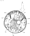
FIG. 1 is a perspective view of a mobile robot according to an embodiment of the present disclosure. -
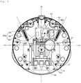
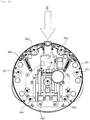
FIG. 2 is a plan view of an interior of a mobile robot excluding a bumper according to an embodiment of the present disclosure. -
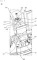
FIG. 3 is a perspective view illustrating an assembly structure of a position restoring module according to an embodiment of the present disclosure. -
FIG. 4 is an assembled cross-sectional perspective view of a bumper guide module according to an embodiment of the present disclosure. -
FIG. 5 is an exploded perspective view of a bumper guide module according to an embodiment of the present disclosure. -
FIG. 6A is a plan view of a bumper guide module according to an embodiment of the present disclosure. -
FIG. 6B is a plan view of a bumper guide module in the case where there is no external force according to an embodiment of the present disclosure. -
FIG. 6C is a plan view of a bumper guide module in the case where an external force is applied on the front side according to an embodiment of the present disclosure. -
FIG. 6D is a plan view of a bumper guide module in the case where an external force is applied on the left side according to an embodiment of the present disclosure. -
FIG. 6E is a plan view of a bumper guide module in the case where an external force is applied on the right side according to an embodiment of the present disclosure. -
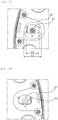
FIG. 7 is an exploded perspective view of a sensing module according to an embodiment of the present disclosure. -
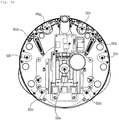
FIG. 8A is a plan view of a mobile robot in the case where there is no external force according to an embodiment of the present disclosure. -
FIG. 8B is a plan view of a mobile robot in the case where an external force is applied on the front side according to an embodiment of the present disclosure. -
FIG. 8C is a plan view of a mobile robot in the case where an external force is applied on the front left side according to an embodiment of the present disclosure. -
FIG. 8D is a plan view of a bumper guide module in the case where an external force is applied on the front right side according to an embodiment of the present disclosure. - Advantages and features of the present disclosure and methods for accomplishing the same will be more clearly understood from exemplary embodiments described below with reference to the accompanying drawings. However, the present disclosure is not limited to the following embodiments, but may be implemented in various different forms. The embodiments are provided only to complete disclosure of the present disclosure and to fully provide a person having ordinary skill in the art, to which the present disclosure pertains, with the category of the present disclosure, and the present disclosure will be defined by the scope of the appended claims. Wherever possible, like reference numerals generally denote like elements through the specification.
- In the following description, the terms indicating directions, such as "front (F)," "rear (R)," "left (Le)," "right (RI)," "up (U)," "down (D)," and the like, are defined based on a traveling direction of the mobile robot. These terms, however, are used merely to provide a better understanding of the present disclosure, and it is apparent that the directions can be defined differently by difference references.
- The terms, "first," "second," "third," etc., used in this disclosure, do not necessarily denote any order, importance, or hierarchy, but rather the terms are used to merely distinguish one element from another. For example, only a second element may be included without a first element.
- The term "mop" used herein may be made of various materials, such as fabric or paper, and may be intended for repetitive use by washing or for one-time use.
- Th present disclosure may be applied to a mobile robot which may be manually moved by a user, a robot cleaner which may autonomously move, and the like. The following description will be given using a mobile robot as an example.
- A mobile robot 1 according to an embodiment of the present disclosure has a
body 20 including a controller. The mobile robot 1 includes amop module 40 configured to mop a floor while being in contact with the floor (surface to be cleaned). The mobile robot 1 includes a sweep module configured to collect foreign materials on the floor. - The
mop module 40 is disposed below thebody 20 and supports thebody 20. Thesweep module 20 is disposed below thebody 20 and supports thebody 20. In the embodiment, thebody 20 is supported by themop module 40 and the sweep module. Thebody 20 forms an exterior of the mobile robot 1. Thebody 20 is disposed to connect themop module 40 and the sweep module. - The
mop module 40 may form an exterior. Themop module 40 is disposed below thebody 20 and at the rear of the sweep module. Themop module 40 provides a driving force for movement of the mobile robot 1. In order to move the mobile robot 1, themop module 40 is desirably disposed at the rear of the mobile robot 1. - The
mop module 40 includes at least one floor cloth 411 which wipes the floor while rotating. Themop module 40 includes at least one spin mop 41, which when viewed from the top, rotates clockwise or counterclockwise. The spin mop 41 is in contact with the floor. - In the embodiment, the
mop module 40 includes a pair of spin mops 41a and 41b. The pair of spin mops 41a and 41b rotate clockwise or counter-clockwise when viewed from above, and mops the floor during the rotation. Of the pair of the spin mops 41a and 41b, a spin mop, which is located at the left side when viewed from the front in a traveling direction of the mobile robot 1, is defined as a left spin mop 41a, and a spin mop located at the right side is defined as a right spin mop 41b. - Each of the left spin mop 41a and the right spin mop 41b rotates about a rotation axis. The rotation axis is disposed vertically. The left spin mop 41a and the right spin mop 41b may rotate independently of each other.
- Each of the left spin mop 41a and the right spin mop 41b includes the floor cloth 411, a rotary plate 412, and a spin shaft 414. Each of the left spin mop 41a and the right spin mop 41b includes a water accommodating part 413.
- The sweep module may form an exterior. The sweep module is disposed at the front of the
mop module 40. In order to prevent themop module 40 from first coming into contact with foreign materials on the floor, the sweep module is desirably disposed at the front in a traveling direction of the mobile robot 1. - The sweep module is spaced apart from the
mop module 40. The sweep module is disposed at the front of themop module 40 and is in contact with the floor. The sweep module collects foreign materials from the floor. - While being in contact with the floor, the sweep module collects foreign materials, located in front of the sweep module, into the inside while the mobile robot 1 moves. The sweep module is disposed below the
body 20. The sweep module has a width from side to side which is smaller than a width from side to side of themop module 40. - The
bumper 30 may surround at least a portion of an outer circumference of thebody 20, may surround the entire outer circumference of thebody 20, or may surround a top portion of thebody 20. Thebumper 30 includes acase 31, which forms an exterior of the mobile robot 1, and a base 32 which is disposed below thecase 31. - The
case 31 forms a lateral surface and a top surface of thebumper 30. The base 32 forms a bottom surface of thebumper 30. - In the embodiment, the
case 31 has a cylindrical shape with an open bottom surface. When viewed from above, the overall shape of thecase 31 is a circle. As a plane of thecase 31 has a circular shape, a radius of gyration during rotation may be minimized. - The
case 31 includes: atop wall 311 having a circular shape; and aside wall 312 which is integrally formed with thetop wall 311 and extends downward from the edge of thetop wall 311. - The
side wall 312 is partially open. An open portion of theside wall 312 is defined as a water tank insertion hole 313, through which awater tank 81 is detachably installed. The water tank insertion hole 313 is formed at the rear in a traveling direction of the mobile robot 1. As thewater tank 81 is inserted through the water tank insertion hole 313, the water tank insertion hole 313 is desirably disposed adjacent to themop module 40. - The
mop module 40 is connected to thebase 32, and the sweep module 80 is connected to thebase 32. A controller Co and a battery Bt are provided in an internal space formed by thecase 31 and thebase 32. Further, a mop driving part is disposed in thebody 20. The water supply module 80 is disposed at thebody 20. - The
base 32 includes: a base body 321 which covers the open bottom surface of thecase 31; a base guard 322 which is formed along an outer edge of the base body 321 and protrudes downward from the edge of the base body 321; and an insertion hole 323 which is vertically formed through the base body 321, and into which the sweep module 2000 is detachably inserted. - Hereinafter, a bumper guide structure will be described with reference to
FIGS. 1 to 8 . - The bumper guide structure includes: a
position restoring module 60 which provides a restoring force toward a position before impact when the impact is applied to the mobile robot; abumper guide module 50 which guides the mobile robot to the position before impact while the position is restored; and animpact sensing module 70 which senses the impact applied to the mobile robot. - The
bumper guide module 50 will be described below with reference toFIGS. 2 to 5 . - The
bumper guide module 50 is a device which allows thebumper 30 to move within a predetermined range when an impact is applied, and which guides thebumper 30 to a position before impact when thebumper 30 moves. - The
bumper guide module 50 has aguide hole 51 formed at thebumper 30 or thebody 20, and a protrudingguider 53 which is inserted into the guide hole and moves inside the guide hole. - The shape of the
guide hole 511 will be described below with reference toFIGS. 2 and5 . - The
guide hole 51 is formed at thebumper 30 or thebody 20. As illustrated inFIGS. 2 and5 , theguide hole 51 may be formed through thebumper 30, and may be formed at thebody 20 within a range which may be easily modified by those skilled in the art. - The
guide hole 51 may be horizontal to the ground as illustrated inFIGS. 2 and5 . - The
guide hole 51 has anorigin point 511, at which the protruding guider is located when no impact is applied. When the protruding guider is positioned at theorigin point 511, there is a space in thebumper 30 which is separated from thebody 20. The protrudingguider 53 may have a predetermined width from its central point, and thus, the central point of the protrudingguider 53 may not coincide with theorigin point 511 of theguide hole 51. - A
first part 512 extends leftward from theorigin point 511 of theguide hole 51. Thefirst part 512 may extend linearly. Thefirst part 512 may have a shape which is convex rearward or a shape which is convex forward. - A
second part 513 extends rightward from theorigin point 511 of the guide hole. Thesecond part 513 may be symmetrical to thefirst part 512. Thesecond part 513 may extend linearly. Thesecond part 513 may have a shape which is convex rearward or a shape which is convex forward. - A
third part 514 connects a left end of thefirst part 512 and a right end of thesecond part 513. As illustrated inFIGS. 2 and5 , thefirst part 512 may extend forward or rearward (not shown). - The
first part 512, thesecond part 513 and thethird part 514 are connected with each other to form a closed loop. Thefirst part 512, thesecond part 513 and thethird part 514 are connected with each other to form a closed space. - According to a first embodiment of the present disclosure, the
first part 512 may extend to the front left side from theorigin point 511, and thesecond part 513 may extend to the front right side from theorigin point 511. Thefirst part 512 and thesecond part 513 may be symmetrical to each other. Thefirst part 512 and thesecond part 513 may be linearly formed, or may have a curved surface. - An angle θ1, formed between the
first part 512 and thesecond part 513 with respect to theorigin point 511, may be an obtuse angle. When viewed from the front of the mobile robot, the angle θ1, formed between thefirst part 512 and thesecond part 513, may be within a range of 90 degrees to 180 degrees. - According to a second embodiment of the present disclosure, the
origin point 511 may be located behind the left end of thefirst part 512 or the right end of thesecond part 513. - When viewed from above, the
origin point 511 may be located at a rearmost position in a cross-section of theguide hole 51. Accordingly, when impact is applied to a front side or to a lateral side, thebumper 30 may move to a rear side or to a lateral side. When an external force is applied on a lateral side, thebumper 30 may move to an opposite lateral side, and more particularly to a rear lateral side, without moving to the front lateral side. - While in operation, the mobile robot moves forward or rotates, such that there is no need to consider the impact on the rear side. Accordingly, by having the
origin point 511 at the rearmost position, it is possible to prevent thebumper 30 from moving to the front side meaninglessly, thereby preventing vibrations and increasing stability. - The
third part 514 may extend forward from the left end of thefirst part 512 or the right end of thesecond part 513, and may have a curved surface which is convex forward. The protruding guider may move inside thethird part 514, and thebumper 30 may perform a curved movement while moving rearward. While the mobile robot rotates when colliding with an obstacle on the lateral side, thebumper 30 may perform a curved movement during the rearward movement, thereby allowing the mobile robot to smoothly rotate. - According to a third embodiment, the
first part 512 may extend from theorigin point 511 to the front left side in a radial direction, thesecond part 513 may extend from theorigin point 511 to the front right side in a radial direction, and thethird part 514 may extend forward from the left end of thefirst part 512 to the right end of thesecond part 513 to form a curved surface which is convex forward. Thefirst part 512, thesecond part 513 and thethird part 514 may have a fan shape. A curved surface of the fan shape faces forward, and a central portion thereof faces rearward. - The shape of the protruding
guider 53 will be described with reference toFIGS. 5 and6 . - The protruding
guider 53 is formed at thebumper 30 or thebody 20. The protrudingguider 53 is formed at a position corresponding to theguide hole 51. Theguide hole 51 may protrude from thebody 20 as illustrated inFIGS. 5 and6 . The protrudingguider 53 may protrude from the top of a protruding surface, which protrudes upward from thebody 20. - The protruding
guider 53 has a lateral surface which is adjacent to the inner surface of theguide hole 51. - A
separation prevention cap 55 is a device for preventing the protrudingguider 53, which moves while being inserted into theguide hole 51, from being separated therefrom. Theseparation prevention cap 55 is connected to the top of the protrudingguider 53. - Referring to
FIG. 6A , a width L1 of one side of theseparation prevention cap 55 is not smaller than a width L2 of theguide hole 51 formed at a position which vertically corresponds to the width L1 of theseparation prevention cap 55. Theseparation prevention cap 55 may have a disk shape, and a diameter corresponding to the width L1 of theseparation prevention cap 55 may not be smaller than the width L2 of theguide hole 51, thereby producing an effect in that the connection of the protrudingguider 53 and theguide hole 51 may not be separated. - Referring to
FIG. 5 , the top of thebumper 30 is adjacent to theseparation prevention cap 55, and the bottom thereof is adjacent to the top surface of thebody 20. - The protruding
guider 53 includes: afemale screw 531 formed at the center thereof; ahole 551 which is vertically formed through the center of theseparation prevention cap 55; and amale screw 533 which is screwed into thefemale screw 531 through thehole 551. Accordingly, theseparation prevention cap 55 may freely rotate about themale screw 533 as a rotation axis, and friction with thebumper 30 may be minimized by the free rotation of theseparation prevention cap 55. - Referring to
FIG. 5 , the protrudingguider 53 includes aprotrusion 553 which protrudes upward from thebumper 30. Theprotrusion 553 may be formed in a region which vertically overlaps theseparation prevention cap 55. Theprotrusion 553 may be adjacent to the lower end of theseparation prevention cap 55. Theprotrusion 553 may be disposed on a circumference of theguide hole 51. There may be a plurality ofprotrusions 553. Theprotrusion 553 has the effect of reducing friction by minimizing a contact area between the lower end of theseparation prevention cap 55 and the upper end of thebumper 30. - According to an embodiment of the present disclosure, the
body 20 includes aprotrusion 554 which protrudes upward from thebody 20. Theprotrusion 554 may be disposed in a region which vertically overlaps thebumper 30. Theprotrusion 554 may be adjacent to the lower end of thebumper 30. There may be a plurality ofprotrusions 554. Theprotrusion 554 has the effect of reducing friction by minimizing a contact area between the lower end of thebumper 30 and the upper end of thebody 20. - The mobile robot may include two or more
bumper guide modules 50. The mobile robot may include two or morebumper guide modules 50 which are symmetrical to each other with respect to a vertical central axis. By having thebumper guide modules 50 which are disposed symmetrical to each other, even when one of thebumper guide modules 50 breaks down, the other may guide thebumper 30. - The mobile robot may include a
bumper guide module 50a which is disposed at the vertical central axis Ay. The mobile robot may further include a position detection sensor in thebumper guide module 50 disposed at the vertical central axis Ay. - An angle θ2, formed by a left
bumper guide module 50f, a point of intersection between the vertical central axis Ay and a horizontal central axis Ax, and a rightbumper guide module 50c, may be equal to the angle θ1 formed between thefirst part 512 and thesecond part 513. - The
position restoring module 60 will be described below with reference toFIG. 2 . When thebumper 30 is moved by impact, theposition restoring module 60 provides a restoring force so that the position of thebumper 30 may be restored to a position before impact. Theposition restoring module 60 has one side which is connected to thebody 20 and the other side which is connected to thebumper 30, and includes anelastic member 65. - The
position restoring module 60 may further include: a first protrudingmember 61 which protrudes upward from one side of thebody 20; and a second protrudingmember 63 which protrudes from one side of thebumper 30 and is disposed behind the first protrudingmember 61. Theelastic member 65 may connect the first protrudingmember 61 and the second protrudingmember 63. - The first protruding
member 61 may be disposed at 45 degrees to the front from a central point where the vertical central axis Ax and the horizontal central axis Ax intersect. - Referring to
FIGS. 2 and7 , the first protrudingmember 61 may protrude from the top of asensing module case 71. The first protrudingmember 61 may be vertical to ahinge 73 of a sensing module. - The
position restoring module 60 may further include a leftposition restoring module 60a and a rightposition restoring module 60b, and the leftposition restoring module 60a and the rightposition restoring module 60b may be symmetrical to each other with respect to the vertical central axis Ay. - Referring to
FIG. 3 , the leftposition restoring module 60a and the rightposition restoring module 60b may be disposed diagonally. The leftposition restoring module 60a and the rightposition restoring module 60b may be disposed in a radial direction. An angle θ3, formed between the leftposition restoring module 60a and the rightposition restoring module 60b, may be an acute angle when viewed from the front. Accordingly, the leftposition restoring module 60a is tensioned most when impact is applied on the left side, and the rightposition restoring module 60b is tensioned most when impact is applied on the right side. - While in operation, the mobile robot mostly moves forward, such that impulse at a front side is greater than impulse at a lateral side. Accordingly, as the
position restoring module 60 is disposed diagonally, a greater restoring force may be provided for an impact on the front side compared to an impact on the lateral side. - Referring to
FIG. 3 , the angle θ3, formed between the leftposition restoring module 60a and the rightposition restoring module 60b, may be smaller than the angle θ1 formed between thefirst part 512 and thesecond part 513. An angle, formed by a longitudinal extension line of a left elastic member 65a and a longitudinal extension line of a right elastic member 65b, may be smaller than the angle θ1 formed between thefirst part 512 and thesecond part 513. When restored after collision, the protrudingguider 53 may move toward theorigin point 511 after coming into contact with thefirst part 512 or thesecond part 513, thereby minimizing vibrations and stably reaching theorigin point 511. - An
impact sensing module 70 will be described below with reference toFIG. 7 . - The
impact sensing module 70 is a device for determining whether there is impact by sensing the movement of thebumper 30 when the position of thebumper 30 is moved by an external force or impact. Theimpact sensing module 70 is disposed at one side of thebody 20, and includes a bar which is adjacent to thebumper 30 and moves along with thebumper 30 when impact is applied. - The
impact sensing module 70 may include: asensing module case 71 disposed at one side of thebody 20; and ahinge 73 disposed inside thesensing module case 71 and having a rotation axis which is perpendicular to the floor. Theimpact sensing module 70 may include bars, including: afirst bar 75, one side of which is adjacent to an inner surface of thebumper 30 and the other side of which is connected to thehinge 73; and asecond bar 76, on one side of which adetection sensor 77 is disposed, and the other side of which is connected to thehinge 73. - The
first bar 75 and thesecond bar 76 may form an acute angle with respect to thehinge 73. - The
first bar 75 extends in a radial direction from thehinge 73, to be curved toward thebumper 30. - The
detection sensor 77 is a sensor for detecting the movement of thesecond bar 76, and checks whether there is impact by sensing the movement of thebumper 30 which is adjacent to thesecond bar 76. Thedetection sensor 77 includes a photo interrupter. Thedetection sensor 77 may include: a first sensor which penetrates from above into thesensing module case 71 to be connected thereto; and a second sensor which is connected to thesecond bar 76. Based on a radial direction, the first sensor is disposed to surround three surfaces, i.e., an inner surface, an outer surface and a top surface, of the second sensor. In the case where the second sensor rotates about thehinge 73, the first sensor may sense the change and transmit data to the controller. - Referring to
FIG. 3 , there may be a plurality ofimpact sensing modules 70, including a left impact sensing module 70a, which is disposed on the front left side, and a right impact sensing module 70b, which is disposed on the front right side. With respect to a point of intersection between the vertical central axis Ay and the horizontal central axis Ax, an angle θ3 formed between the left impact sensing module 70a and the right impact sensing module 70b may be smaller than the angle θ1 formed between thefirst part 512 and thesecond part 513. With respect to a point of intersection between the vertical central axis Ay and the horizontal central axis Ax, an angle θ4 formed between the left impact sensing module 70a and the right impact sensing module 70b may be 90 degrees. - An operation of the mobile robot according to the present disclosure, which is configured as described above, will be described below.
- Referring to a use state view, when the mobile robot collides with an obstacle head-on, the protruding
guider 53 is positioned at the front of theguide hole 51 as illustrated inFIG. 6B . In the case where a left side of the mobile robot collides with an obstacle, the protrudingguider 53 is positioned at the left side of theguide hole 51. In the case where a right side of the mobile robot collides with an obstacle, the protrudingguider 53 is positioned at the right side of theguide hole 51. -
FIG. 8b illustrates a case where the mobile robot collides with an obstacle head-on. In this case, thebumper 30 moves to the rear side of thebody 20. In all thebumper guide modules 50, the protrudingguider 53 moves to the front side of theguide hole 51. In theposition restoring module 60, all theelastic members 65 are tensioned, and a resultant of restoring forces of the left elastic member 65a and the right elastic member 65b is 0N at the left/right sides, and is present only at the front. In theimpact sensing module 70, the left/right sensing modules sense the movement. -
FIG. 8C illustrates a case where a left side of the mobile robot, which moves forward, collides with an obstacle. A moment is generated counterclockwise (CCW) in the mobile robot, and thebumper 30 turns to the left and moves rearward. In thebumper guide module 50, the protrudingguider 53 of the front leftbumper guide module 50g moves the most to the front side, and the protrudingguider 53 of the rear rightbumper guide module 50d does not move. In theposition restoring module 60, the left elastic member 65a is tensioned most, and the right elastic member 65d is not tensioned or is least tensioned. When impact is applied on the front side, twoelastic members 65 are tensioned, but when impact is applied on the lateral side, only oneelastic member 65 is tensioned, such that a restoring force for the impact on the lateral side is reduced compared to the impact on the front side. In theimpact sensing module 70, the left sensing module senses the movement, but the right sensing module does not sense the movement. -
FIG. 8D illustrates a case where a right side of the mobile robot, which moves forward, collides with an obstacle. A moment is generated clockwise (CW) in the mobile robot, and thebumper 30 turns to the right, which is an opposite side to the case ofFIG. 8C , such that a description thereof will be omitted. - According to the present disclosure, the mobile robot has one or more of the following effects.
- Firstly, as the origin point of the guide hole is located behind the first part or the second part, the bumper may freely move within a predetermined range when an external force is applied, and may return to the origin point.
- Secondly, the position restoring module is disposed diagonally, such that the same restoring force may be provided for different impulses of a side impact and a front impact.
- Thirdly, by using two fan-shaped detection sensors, the front impact or the side impact may be detected, as well as a small external force.
- While the present disclosure has been shown and described with reference to the preferred embodiments thereof, it should be understood that the present disclosure is not limited to the aforementioned specific embodiments, and various modifications and variations may be made by those skilled in the art without departing from the scope of the invention as defined by the appended claims, and the modified implementations should not be construed independently of the technical idea or prospect of the present disclosure.
Claims (15)
- A mobile robot, comprising:a body (20);a bumper (30) which is spaced apart from the body (20) and surrounds at least a portion of an outer circumference of the body (20);a position restoring module (60), with one side being connected to the body (20) and the other side being connected to the bumper (30), and having an elastic member (65);a bumper guide module (50), having a guide hole (51) which is formed at one side of the bumper (30), and a protruding guider (53) which corresponds to the guide hole (51) in the body (20) and is inserted into the guide hole (51) to move inside the guide hole (51); andan impact sensing module (70) disposed at one side of the body (20), and having a bar (75, 76) which is adjacent to the bumper (30) and moves along with the bumper (30) when impact is applied, and a detection sensor (77) configured to detect movement of the bar (75, 76).
- The mobile robot of claim 1, wherein the guide hole (51) comprises:an origin point (511), at which the protruding guider (53) is located when no impact is applied;a first part (512) which extends leftward from the origin point (511);a second part (513) which extends rightward from the origin point (511); anda third part (514) which connects a left end of the first part (512) and a right end of the second part (513) .
- The mobile robot of claim 2, wherein the first part (512) extends to a front left side, and the second part (513) extends to a front right side.
- The mobile robot of claim 3, wherein an angle formed between the first part (512) and the second part (513) is an obtuse angle.
- The mobile robot of any one of claims 2 to 4, wherein the origin point (511) is located behind the left end of the first part (512) or the right end of the second part (513).
- The mobile robot of any one of claims 2 to 5, wherein the third part (514) extends forward from the left end of the first part (512) or the right end of the second part (513), and has a curved surface which is convex forward.
- The mobile robot of any one of claims 2 to 6, wherein the first part (512) or the second part (513) extends from the origin point (511) in a radial direction, and the third part (514) extends forward from the left side of the first part (512) or from the right side of the second part (513) to form a curved surface which is convex forward.
- The mobile robot of claim 7, wherein the first part (512) to the third part (514) have a fan shape.
- The mobile robot of any one of claims 2 to 8, further comprising a separation prevention cap (55) which is connected to a top of the protruding guider.
- The mobile robot of claim 9, wherein when viewed from above, a width of one side of the separation prevention cap (55) is longer than a width of the guide hole (51) formed at a position which vertically corresponds to the width of the separation prevention cap (55).
- The mobile robot of claim 9 or 10, wherein the protruding guider (53) further comprises:a female screw (531) which is formed at a center thereof;a hole (551) which is formed through a center of the separation prevention cap (55); anda male screw (533) which is screwed into the female screw (531) through the center of the separation prevention cap (55).
- The mobile robot of claim 9, further comprising at least one or more protrusions (553), which protrude upward from the bumper (30), and are disposed in a region which vertically overlaps the separation prevention cap (55).
- The mobile robot of any one of the preceding claims, comprising two or more bumper guide modules which are symmetrical to each other with respect to a vertical central axis.
- The mobile robot of any one of the preceding claims, comprising two or more bumper guide modules (50) which are disposed on an outer circumference of the body (20).
- The mobile robot of any one of the preceding claims, wherein the impact sensing module (70) comprises:a sensing module case (71) disposed at one side of the body (20);a hinge (73) disposed inside the sensing module case (71) and having a rotation axis which is perpendicular to the floor;a first bar (75), one side of which is adjacent to an inner surface of the bumper (30) and the other side of which is connected to the hinge(73); anda second bar (76), on one side of which a detection sensor (77) for detecting movement is disposed, and the other side of which is connected to the hinge (73).
Applications Claiming Priority (1)
| Application Number | Priority Date | Filing Date | Title |
|---|---|---|---|
| KR1020190093476A KR102314535B1 (en) | 2019-07-31 | 2019-07-31 | The moving robot |
Publications (2)
| Publication Number | Publication Date |
|---|---|
| EP3771391A1 true EP3771391A1 (en) | 2021-02-03 |
| EP3771391B1 EP3771391B1 (en) | 2023-05-24 |
Family
ID=71894682
Family Applications (1)
| Application Number | Title | Priority Date | Filing Date |
|---|---|---|---|
| EP20188620.7A Active EP3771391B1 (en) | 2019-07-31 | 2020-07-30 | Mobile robot |
Country Status (5)
| Country | Link |
|---|---|
| US (1) | US11648898B2 (en) |
| EP (1) | EP3771391B1 (en) |
| KR (1) | KR102314535B1 (en) |
| TW (1) | TWI766325B (en) |
| WO (1) | WO2021020906A1 (en) |
Citations (5)
| Publication number | Priority date | Publication date | Assignee | Title |
|---|---|---|---|---|
| KR20060118903A (en) | 2005-05-17 | 2006-11-24 | 엘지전자 주식회사 | Bumper Device of Robot Cleaner |
| EP2155032A2 (en) * | 2007-05-09 | 2010-02-24 | Irobot Corporation | Compact autonomous coverage robot |
| KR20130005513A (en) | 2011-07-06 | 2013-01-16 | 주식회사 유진로봇 | Bumper assembly for moving robot |
| US20190038107A1 (en) * | 2017-08-07 | 2019-02-07 | Lg Electronics Inc. | Robot cleaner |
| KR20190053156A (en) * | 2019-05-08 | 2019-05-17 | 엘지전자 주식회사 | Moving Robot |
Family Cites Families (12)
| Publication number | Priority date | Publication date | Assignee | Title |
|---|---|---|---|---|
| EP2154031A1 (en) * | 2008-08-12 | 2010-02-17 | Koninklijke Philips Electronics N.V. | A mobile robotic device having a collision sensor |
| KR101313776B1 (en) * | 2011-09-21 | 2013-10-01 | 한국로봇융합연구원 | Bumper assembly and cleaning robot having the same |
| KR20160104429A (en) | 2015-02-26 | 2016-09-05 | 에브리봇 주식회사 | A robot cleaner and a method for operating it |
| KR101979760B1 (en) * | 2016-07-14 | 2019-05-17 | 엘지전자 주식회사 | Moving Robot |
| KR101712867B1 (en) * | 2016-07-27 | 2017-03-07 | 주식회사 나린알앤디 | Bumper for absorption of impact in robot cleaner |
| FR3055787B1 (en) * | 2016-09-13 | 2019-03-22 | Seb S.A. | SOIL CLEANING ROBOT |
| TWI634403B (en) | 2017-01-26 | 2018-09-01 | 好樣科技有限公司 | Automatic cleaning machine and control method thereof |
| CN111093451B (en) * | 2017-09-04 | 2021-11-02 | 千叶工业大学 | Self-propelled sweeper |
| JPWO2019073590A1 (en) * | 2017-10-13 | 2020-07-16 | 学校法人千葉工業大学 | Self-propelled vacuum cleaner |
| US11330953B2 (en) * | 2019-09-30 | 2022-05-17 | Irobot Corporation | Vertical sensing in an autonomous cleaning robot |
| CN111035331B (en) * | 2019-12-09 | 2021-07-02 | 上海高仙自动化科技发展有限公司 | Water absorption rake assembly and cleaning robot |
| AU2020416330B2 (en) * | 2019-12-30 | 2024-06-13 | Lg Electronics Inc. | Robot cleaner |
-
2019
- 2019-07-31 KR KR1020190093476A patent/KR102314535B1/en active Active
-
2020
- 2020-07-30 US US16/943,230 patent/US11648898B2/en active Active
- 2020-07-30 WO PCT/KR2020/010072 patent/WO2021020906A1/en not_active Ceased
- 2020-07-30 EP EP20188620.7A patent/EP3771391B1/en active Active
- 2020-07-31 TW TW109126080A patent/TWI766325B/en active
Patent Citations (5)
| Publication number | Priority date | Publication date | Assignee | Title |
|---|---|---|---|---|
| KR20060118903A (en) | 2005-05-17 | 2006-11-24 | 엘지전자 주식회사 | Bumper Device of Robot Cleaner |
| EP2155032A2 (en) * | 2007-05-09 | 2010-02-24 | Irobot Corporation | Compact autonomous coverage robot |
| KR20130005513A (en) | 2011-07-06 | 2013-01-16 | 주식회사 유진로봇 | Bumper assembly for moving robot |
| US20190038107A1 (en) * | 2017-08-07 | 2019-02-07 | Lg Electronics Inc. | Robot cleaner |
| KR20190053156A (en) * | 2019-05-08 | 2019-05-17 | 엘지전자 주식회사 | Moving Robot |
Also Published As
| Publication number | Publication date |
|---|---|
| KR102314535B1 (en) | 2021-10-18 |
| EP3771391B1 (en) | 2023-05-24 |
| WO2021020906A1 (en) | 2021-02-04 |
| TW202108066A (en) | 2021-03-01 |
| TWI766325B (en) | 2022-06-01 |
| KR20210015125A (en) | 2021-02-10 |
| US11648898B2 (en) | 2023-05-16 |
| US20210031371A1 (en) | 2021-02-04 |
Similar Documents
| Publication | Publication Date | Title |
|---|---|---|
| AU2020436036B2 (en) | Robot cleaner | |
| EP3666152B1 (en) | Robot cleaner | |
| US8209053B2 (en) | Cleaning robot | |
| KR102085338B1 (en) | A robot cleaner and driving control method thereof | |
| EP1897476B1 (en) | Cleaning robot | |
| US10624518B2 (en) | Robot cleaner and method for controlling the same | |
| KR101602790B1 (en) | A robot cleaner and a method for operating it | |
| US10624517B2 (en) | Robot cleaner and method for controlling the same | |
| US10568480B2 (en) | Robot cleaner | |
| EP1724652B1 (en) | Bumper device of robot cleaner and robot cleaner having the same | |
| KR200481332Y1 (en) | A robot cleaner | |
| KR101970995B1 (en) | A robot cleaner and a method for operating it | |
| KR20160097085A (en) | A robot cleaner and a method for operating it | |
| EP4176791A1 (en) | Robot vacuum | |
| JPWO2018123321A1 (en) | Autonomous traveling vacuum cleaner | |
| EP3771391B1 (en) | Mobile robot | |
| EP4005456B1 (en) | Vacuum cleaner |
Legal Events
| Date | Code | Title | Description |
|---|---|---|---|
| PUAI | Public reference made under article 153(3) epc to a published international application that has entered the european phase |
Free format text: ORIGINAL CODE: 0009012 |
|
| STAA | Information on the status of an ep patent application or granted ep patent |
Free format text: STATUS: REQUEST FOR EXAMINATION WAS MADE |
|
| 17P | Request for examination filed |
Effective date: 20200830 |
|
| AK | Designated contracting states |
Kind code of ref document: A1 Designated state(s): AL AT BE BG CH CY CZ DE DK EE ES FI FR GB GR HR HU IE IS IT LI LT LU LV MC MK MT NL NO PL PT RO RS SE SI SK SM TR |
|
| AX | Request for extension of the european patent |
Extension state: BA ME |
|
| RBV | Designated contracting states (corrected) |
Designated state(s): AL AT BE BG CH CY CZ DE DK EE ES FI FR GB GR HR HU IE IS IT LI LT LU LV MC MK MT NL NO PL PT RO RS SE SI SK SM TR |
|
| GRAP | Despatch of communication of intention to grant a patent |
Free format text: ORIGINAL CODE: EPIDOSNIGR1 |
|
| STAA | Information on the status of an ep patent application or granted ep patent |
Free format text: STATUS: GRANT OF PATENT IS INTENDED |
|
| RIC1 | Information provided on ipc code assigned before grant |
Ipc: A47L 9/28 20060101AFI20230113BHEP |
|
| INTG | Intention to grant announced |
Effective date: 20230130 |
|
| GRAS | Grant fee paid |
Free format text: ORIGINAL CODE: EPIDOSNIGR3 |
|
| GRAA | (expected) grant |
Free format text: ORIGINAL CODE: 0009210 |
|
| STAA | Information on the status of an ep patent application or granted ep patent |
Free format text: STATUS: THE PATENT HAS BEEN GRANTED |
|
| AK | Designated contracting states |
Kind code of ref document: B1 Designated state(s): AL AT BE BG CH CY CZ DE DK EE ES FI FR GB GR HR HU IE IS IT LI LT LU LV MC MK MT NL NO PL PT RO RS SE SI SK SM TR |
|
| REG | Reference to a national code |
Ref country code: GB Ref legal event code: FG4D |
|
| REG | Reference to a national code |
Ref country code: CH Ref legal event code: EP |
|
| REG | Reference to a national code |
Ref country code: DE Ref legal event code: R096 Ref document number: 602020011040 Country of ref document: DE |
|
| REG | Reference to a national code |
Ref country code: AT Ref legal event code: REF Ref document number: 1569032 Country of ref document: AT Kind code of ref document: T Effective date: 20230615 |
|
| REG | Reference to a national code |
Ref country code: IE Ref legal event code: FG4D |
|
| REG | Reference to a national code |
Ref country code: LT Ref legal event code: MG9D |
|
| REG | Reference to a national code |
Ref country code: NL Ref legal event code: MP Effective date: 20230524 |
|
| REG | Reference to a national code |
Ref country code: AT Ref legal event code: MK05 Ref document number: 1569032 Country of ref document: AT Kind code of ref document: T Effective date: 20230524 |
|
| PG25 | Lapsed in a contracting state [announced via postgrant information from national office to epo] |
Ref country code: SE Free format text: LAPSE BECAUSE OF FAILURE TO SUBMIT A TRANSLATION OF THE DESCRIPTION OR TO PAY THE FEE WITHIN THE PRESCRIBED TIME-LIMIT Effective date: 20230524 Ref country code: PT Free format text: LAPSE BECAUSE OF FAILURE TO SUBMIT A TRANSLATION OF THE DESCRIPTION OR TO PAY THE FEE WITHIN THE PRESCRIBED TIME-LIMIT Effective date: 20230925 Ref country code: NO Free format text: LAPSE BECAUSE OF FAILURE TO SUBMIT A TRANSLATION OF THE DESCRIPTION OR TO PAY THE FEE WITHIN THE PRESCRIBED TIME-LIMIT Effective date: 20230824 Ref country code: NL Free format text: LAPSE BECAUSE OF FAILURE TO SUBMIT A TRANSLATION OF THE DESCRIPTION OR TO PAY THE FEE WITHIN THE PRESCRIBED TIME-LIMIT Effective date: 20230524 Ref country code: ES Free format text: LAPSE BECAUSE OF FAILURE TO SUBMIT A TRANSLATION OF THE DESCRIPTION OR TO PAY THE FEE WITHIN THE PRESCRIBED TIME-LIMIT Effective date: 20230524 Ref country code: AT Free format text: LAPSE BECAUSE OF FAILURE TO SUBMIT A TRANSLATION OF THE DESCRIPTION OR TO PAY THE FEE WITHIN THE PRESCRIBED TIME-LIMIT Effective date: 20230524 |
|
| PG25 | Lapsed in a contracting state [announced via postgrant information from national office to epo] |
Ref country code: RS Free format text: LAPSE BECAUSE OF FAILURE TO SUBMIT A TRANSLATION OF THE DESCRIPTION OR TO PAY THE FEE WITHIN THE PRESCRIBED TIME-LIMIT Effective date: 20230524 Ref country code: PL Free format text: LAPSE BECAUSE OF FAILURE TO SUBMIT A TRANSLATION OF THE DESCRIPTION OR TO PAY THE FEE WITHIN THE PRESCRIBED TIME-LIMIT Effective date: 20230524 Ref country code: LV Free format text: LAPSE BECAUSE OF FAILURE TO SUBMIT A TRANSLATION OF THE DESCRIPTION OR TO PAY THE FEE WITHIN THE PRESCRIBED TIME-LIMIT Effective date: 20230524 Ref country code: LT Free format text: LAPSE BECAUSE OF FAILURE TO SUBMIT A TRANSLATION OF THE DESCRIPTION OR TO PAY THE FEE WITHIN THE PRESCRIBED TIME-LIMIT Effective date: 20230524 Ref country code: IS Free format text: LAPSE BECAUSE OF FAILURE TO SUBMIT A TRANSLATION OF THE DESCRIPTION OR TO PAY THE FEE WITHIN THE PRESCRIBED TIME-LIMIT Effective date: 20230924 Ref country code: HR Free format text: LAPSE BECAUSE OF FAILURE TO SUBMIT A TRANSLATION OF THE DESCRIPTION OR TO PAY THE FEE WITHIN THE PRESCRIBED TIME-LIMIT Effective date: 20230524 Ref country code: GR Free format text: LAPSE BECAUSE OF FAILURE TO SUBMIT A TRANSLATION OF THE DESCRIPTION OR TO PAY THE FEE WITHIN THE PRESCRIBED TIME-LIMIT Effective date: 20230825 |
|
| PG25 | Lapsed in a contracting state [announced via postgrant information from national office to epo] |
Ref country code: FI Free format text: LAPSE BECAUSE OF FAILURE TO SUBMIT A TRANSLATION OF THE DESCRIPTION OR TO PAY THE FEE WITHIN THE PRESCRIBED TIME-LIMIT Effective date: 20230524 |
|
| PG25 | Lapsed in a contracting state [announced via postgrant information from national office to epo] |
Ref country code: SK Free format text: LAPSE BECAUSE OF FAILURE TO SUBMIT A TRANSLATION OF THE DESCRIPTION OR TO PAY THE FEE WITHIN THE PRESCRIBED TIME-LIMIT Effective date: 20230524 |
|
| PG25 | Lapsed in a contracting state [announced via postgrant information from national office to epo] |
Ref country code: SM Free format text: LAPSE BECAUSE OF FAILURE TO SUBMIT A TRANSLATION OF THE DESCRIPTION OR TO PAY THE FEE WITHIN THE PRESCRIBED TIME-LIMIT Effective date: 20230524 Ref country code: SK Free format text: LAPSE BECAUSE OF FAILURE TO SUBMIT A TRANSLATION OF THE DESCRIPTION OR TO PAY THE FEE WITHIN THE PRESCRIBED TIME-LIMIT Effective date: 20230524 Ref country code: RO Free format text: LAPSE BECAUSE OF FAILURE TO SUBMIT A TRANSLATION OF THE DESCRIPTION OR TO PAY THE FEE WITHIN THE PRESCRIBED TIME-LIMIT Effective date: 20230524 Ref country code: EE Free format text: LAPSE BECAUSE OF FAILURE TO SUBMIT A TRANSLATION OF THE DESCRIPTION OR TO PAY THE FEE WITHIN THE PRESCRIBED TIME-LIMIT Effective date: 20230524 Ref country code: DK Free format text: LAPSE BECAUSE OF FAILURE TO SUBMIT A TRANSLATION OF THE DESCRIPTION OR TO PAY THE FEE WITHIN THE PRESCRIBED TIME-LIMIT Effective date: 20230524 Ref country code: CZ Free format text: LAPSE BECAUSE OF FAILURE TO SUBMIT A TRANSLATION OF THE DESCRIPTION OR TO PAY THE FEE WITHIN THE PRESCRIBED TIME-LIMIT Effective date: 20230524 |
|
| REG | Reference to a national code |
Ref country code: DE Ref legal event code: R097 Ref document number: 602020011040 Country of ref document: DE |
|
| PG25 | Lapsed in a contracting state [announced via postgrant information from national office to epo] |
Ref country code: MC Free format text: LAPSE BECAUSE OF FAILURE TO SUBMIT A TRANSLATION OF THE DESCRIPTION OR TO PAY THE FEE WITHIN THE PRESCRIBED TIME-LIMIT Effective date: 20230524 |
|
| PG25 | Lapsed in a contracting state [announced via postgrant information from national office to epo] |
Ref country code: MC Free format text: LAPSE BECAUSE OF FAILURE TO SUBMIT A TRANSLATION OF THE DESCRIPTION OR TO PAY THE FEE WITHIN THE PRESCRIBED TIME-LIMIT Effective date: 20230524 |
|
| REG | Reference to a national code |
Ref country code: CH Ref legal event code: PL |
|
| REG | Reference to a national code |
Ref country code: BE Ref legal event code: MM Effective date: 20230731 |
|
| PG25 | Lapsed in a contracting state [announced via postgrant information from national office to epo] |
Ref country code: LU Free format text: LAPSE BECAUSE OF NON-PAYMENT OF DUE FEES Effective date: 20230730 |
|
| PG25 | Lapsed in a contracting state [announced via postgrant information from national office to epo] |
Ref country code: LU Free format text: LAPSE BECAUSE OF NON-PAYMENT OF DUE FEES Effective date: 20230730 |
|
| PLBE | No opposition filed within time limit |
Free format text: ORIGINAL CODE: 0009261 |
|
| STAA | Information on the status of an ep patent application or granted ep patent |
Free format text: STATUS: NO OPPOSITION FILED WITHIN TIME LIMIT |
|
| REG | Reference to a national code |
Ref country code: IE Ref legal event code: MM4A |
|
| PG25 | Lapsed in a contracting state [announced via postgrant information from national office to epo] |
Ref country code: CH Free format text: LAPSE BECAUSE OF NON-PAYMENT OF DUE FEES Effective date: 20230731 |
|
| 26N | No opposition filed |
Effective date: 20240227 |
|
| PG25 | Lapsed in a contracting state [announced via postgrant information from national office to epo] |
Ref country code: SI Free format text: LAPSE BECAUSE OF FAILURE TO SUBMIT A TRANSLATION OF THE DESCRIPTION OR TO PAY THE FEE WITHIN THE PRESCRIBED TIME-LIMIT Effective date: 20230524 |
|
| PG25 | Lapsed in a contracting state [announced via postgrant information from national office to epo] |
Ref country code: SI Free format text: LAPSE BECAUSE OF FAILURE TO SUBMIT A TRANSLATION OF THE DESCRIPTION OR TO PAY THE FEE WITHIN THE PRESCRIBED TIME-LIMIT Effective date: 20230524 Ref country code: IT Free format text: LAPSE BECAUSE OF FAILURE TO SUBMIT A TRANSLATION OF THE DESCRIPTION OR TO PAY THE FEE WITHIN THE PRESCRIBED TIME-LIMIT Effective date: 20230524 Ref country code: FR Free format text: LAPSE BECAUSE OF NON-PAYMENT OF DUE FEES Effective date: 20230731 Ref country code: BE Free format text: LAPSE BECAUSE OF NON-PAYMENT OF DUE FEES Effective date: 20230731 |
|
| PG25 | Lapsed in a contracting state [announced via postgrant information from national office to epo] |
Ref country code: IE Free format text: LAPSE BECAUSE OF NON-PAYMENT OF DUE FEES Effective date: 20230730 |
|
| PG25 | Lapsed in a contracting state [announced via postgrant information from national office to epo] |
Ref country code: IE Free format text: LAPSE BECAUSE OF NON-PAYMENT OF DUE FEES Effective date: 20230730 |
|
| PG25 | Lapsed in a contracting state [announced via postgrant information from national office to epo] |
Ref country code: BG Free format text: LAPSE BECAUSE OF FAILURE TO SUBMIT A TRANSLATION OF THE DESCRIPTION OR TO PAY THE FEE WITHIN THE PRESCRIBED TIME-LIMIT Effective date: 20230524 |
|
| PG25 | Lapsed in a contracting state [announced via postgrant information from national office to epo] |
Ref country code: BG Free format text: LAPSE BECAUSE OF FAILURE TO SUBMIT A TRANSLATION OF THE DESCRIPTION OR TO PAY THE FEE WITHIN THE PRESCRIBED TIME-LIMIT Effective date: 20230524 |
|
| GBPC | Gb: european patent ceased through non-payment of renewal fee |
Effective date: 20240730 |
|
| PG25 | Lapsed in a contracting state [announced via postgrant information from national office to epo] |
Ref country code: GB Free format text: LAPSE BECAUSE OF NON-PAYMENT OF DUE FEES Effective date: 20240730 |
|
| PG25 | Lapsed in a contracting state [announced via postgrant information from national office to epo] |
Ref country code: CY Free format text: LAPSE BECAUSE OF FAILURE TO SUBMIT A TRANSLATION OF THE DESCRIPTION OR TO PAY THE FEE WITHIN THE PRESCRIBED TIME-LIMIT; INVALID AB INITIO Effective date: 20200730 |
|
| PG25 | Lapsed in a contracting state [announced via postgrant information from national office to epo] |
Ref country code: HU Free format text: LAPSE BECAUSE OF FAILURE TO SUBMIT A TRANSLATION OF THE DESCRIPTION OR TO PAY THE FEE WITHIN THE PRESCRIBED TIME-LIMIT; INVALID AB INITIO Effective date: 20200730 |
|
| PGFP | Annual fee paid to national office [announced via postgrant information from national office to epo] |
Ref country code: DE Payment date: 20250609 Year of fee payment: 6 |
|
| PG25 | Lapsed in a contracting state [announced via postgrant information from national office to epo] |
Ref country code: TR Free format text: LAPSE BECAUSE OF FAILURE TO SUBMIT A TRANSLATION OF THE DESCRIPTION OR TO PAY THE FEE WITHIN THE PRESCRIBED TIME-LIMIT Effective date: 20230524 |