EP3771325A2 - Feeder housing for agricultural machine - Google Patents
Feeder housing for agricultural machine Download PDFInfo
- Publication number
- EP3771325A2 EP3771325A2 EP20187525.9A EP20187525A EP3771325A2 EP 3771325 A2 EP3771325 A2 EP 3771325A2 EP 20187525 A EP20187525 A EP 20187525A EP 3771325 A2 EP3771325 A2 EP 3771325A2
- Authority
- EP
- European Patent Office
- Prior art keywords
- feeder housing
- housing
- agricultural machine
- feeder
- cross member
- Prior art date
- Legal status (The legal status is an assumption and is not a legal conclusion. Google has not performed a legal analysis and makes no representation as to the accuracy of the status listed.)
- Granted
Links
Images



Classifications
-
- A—HUMAN NECESSITIES
- A01—AGRICULTURE; FORESTRY; ANIMAL HUSBANDRY; HUNTING; TRAPPING; FISHING
- A01D—HARVESTING; MOWING
- A01D61/00—Elevators or conveyors for binders or combines
- A01D61/002—Elevators or conveyors for binders or combines transversal conveying devices
-
- A—HUMAN NECESSITIES
- A01—AGRICULTURE; FORESTRY; ANIMAL HUSBANDRY; HUNTING; TRAPPING; FISHING
- A01F—PROCESSING OF HARVESTED PRODUCE; HAY OR STRAW PRESSES; DEVICES FOR STORING AGRICULTURAL OR HORTICULTURAL PRODUCE
- A01F12/00—Parts or details of threshing apparatus
- A01F12/10—Feeders
- A01F12/16—Safety devices
-
- A—HUMAN NECESSITIES
- A01—AGRICULTURE; FORESTRY; ANIMAL HUSBANDRY; HUNTING; TRAPPING; FISHING
- A01D—HARVESTING; MOWING
- A01D41/00—Combines, i.e. harvesters or mowers combined with threshing devices
- A01D41/12—Details of combines
-
- A—HUMAN NECESSITIES
- A01—AGRICULTURE; FORESTRY; ANIMAL HUSBANDRY; HUNTING; TRAPPING; FISHING
- A01D—HARVESTING; MOWING
- A01D75/00—Accessories for harvesters or mowers
- A01D75/18—Safety devices for parts of the machines
- A01D75/187—Removing foreign objects
-
- A—HUMAN NECESSITIES
- A01—AGRICULTURE; FORESTRY; ANIMAL HUSBANDRY; HUNTING; TRAPPING; FISHING
- A01F—PROCESSING OF HARVESTED PRODUCE; HAY OR STRAW PRESSES; DEVICES FOR STORING AGRICULTURAL OR HORTICULTURAL PRODUCE
- A01F12/00—Parts or details of threshing apparatus
- A01F12/10—Feeders
Definitions
- the present invention relates generally to a feeder housing for an agricultural machine, such as a combine harvester.
- a combine harvester has at its front end an intake feeder system that cuts the crop from the ground and feeds it to a threshing mechanism.
- the intake feeder system comprises a header and a feeder housing (also referred to herein as an elevator) that raises the crop to the level of the mouth of the threshing mechanism.
- the feeder housing may be a welded assembly of sheet metal plates.
- the header which takes different forms depending on the type of crop, is wider than the feeder housing and is provided with augers or belts arranged at each side of the header to push the cut crop towards the central feeder housing.
- the threshing mechanism separates the grain from the stalks, or straw, and the chaff. The grain is stored in a tank on board the harvester while the straw and the chaff are discharged from the rear end of the harvester.
- the threshing is carried out by passing the crop between a rotating cylinder and a surrounding concave.
- the cylinder has threshing elements on its surface that separate the grain by beating and crushing the crop against the surrounding concave, and the concave has openings through which the separated grain can fall to be transferred to the storage tank.
- the cylinder may be disposed longitudinally or transversely but the present invention is primarily concerned with harvesters having longitudinal threshing cylinders.
- harvesting machines frequently pick up and ingest rocks and other foreign matter.
- the rocks and foreign matter ingested by the harvesting machine can damage the crop handling mechanisms of the harvesting machine.
- many harvesting machines such as combines, include devices for detecting and separating the rocks and foreign matter from the crops and forage. The separated rocks and foreign matter collect within a rock trap sump of the feeder housing for later discharge and disposal.
- Conventional rock trap sumps include a cavity or chamber formed in the feeder housing for storing the separated rocks and foreign matter and a door for emptying the rocks and foreign matter from the chamber.
- the door is typically hinged adjacent to a rock trap sump opening and pivots to open and close the opening.
- a door latch independently supported adjacent and below the rock trap sump engages and supports the door in a closed position. To empty the chamber, the door latch is actuated to release the door, thereby permitting the door to fall open for the discharge of rocks and foreign matter.
- a reinforced feeder housing for an agricultural machine includes a housing body having a top surface, a bottom surface, and two opposing side surfaces each extending between the top and bottom surfaces.
- the housing body includes a front opening through which crop material is directed into the feeder housing from a header of the agricultural machine, and a rear opening that is substantially opposite the front opening through which crop is expelled from the feeder housing and is delivered to a threshing mechanism of the agricultural machine.
- Various panels of the housing body are reinforced to improve the structural integrity of the feeder housing and prevent damage to the welds in the housing body.
- the feeder housing includes a cross member extending between and either directly or indirectly connecting the opposing side surfaces, a first bracket that is connected to the cross member and one of the side surfaces, and a second bracket that is connected to the cross member and the other of the side surfaces.
- a leading edge of the top panel that at least partially defines the front opening includes (i) connection ends each of which is connected to one of the side panels, and (ii) a central portion extending between the connection ends, wherein the connection ends are positioned forward of the central portion of the leading edge.
- an opening is defined in the bottom panel at a location adjacent a weld between the bottom panel and one of the side panels.
- a cross member is disposed at a location adjacent the rear opening and extends between and either directly or indirectly connects the opposing side surfaces.
- the cross member is connected to each side surface in addition to side panels that are each connected to one of the side surfaces.
- Also described herein is a combine harvester comprising any one of the above-described feeder housings.
- forward when used in connection with the agricultural combine and/or components thereof are usually determined with reference to the direction of forward operative travel of the combine, but again, they should not be construed as limiting.
- longitudinal and “transverse” are determined with reference to the fore-and-aft direction of the combine and are equally not to be construed as limiting.
- a combine harvester 10 has an intake feeder system 12 having a header with a cutter 14 and a reel 16, a feeder housing (or elevator) 18 and a stone separator 20 arranged between the top of the feeder housing 18 and the threshing mechanism 22.
- the stone separator 20 comprises a feed beater 26, in the form of a rotor with projecting paddles, arranged above a rock trap sump 28.
- the feed beater 26 conveys the crop towards the threshing mechanism 22 while rocks and foreign matter, which are generally heavier and denser than the crop, are impacted and downwardly discharged into the interior of the rock trap sump 28.
- the rotation of the feed beater 26 propels the rocks and foreign matter downwardly through straw and chaff and into the rock trap sump. As a result, the rocks and foreign matter are separated from the crop prior and prevented from reaching the threshing mechanism 22.
- the reinforced feeder housing 218, which may also be referred to herein as housing 218, comprises a plurality of metal plates that are welded together (or otherwise fastened) in a rectangular hollow box shape. More particularly, the housing 218 generally includes a bottom member 220, a top member 222, and two side members 224 and 226. Each member 220, 222, 224 and 226 comprises one or more plates that are fastened either directly or indirectly.
- the housing 218 further includes a front opening 228 through which crop material is directed into the housing 218 from the reel 16, and a rear opening 230 through which crop is expelled from the housing 218 and is delivered to the threshing mechanism 22.
- Various automated devices such as a conveyor, may or may not be positioned within the interior of the housing 218 for conveying the crop from the front opening 228 to the rear opening 230.
- one or more tubes 232 and a rear beam 234 extend between the side members 224 and 226 for enhancing the structural integrity of the housing 218.
- a shaft may be positioned within the tube 232.
- a rock trap sump 236 is at least partially formed by a cross member 238.
- the cross member 238 is connected to and extends transversely between the side members 224 and 226.
- the cross member 238 may also be connected the bottom member 220.
- the opening formed by the cross member 238 faces downwardly.
- the sump 236 collects rocks and stones, as described above.
- the stiffness of the cross member 238 is greater than the stiffness of the side members 224 and 226 due at least in part to the structurally stable U-shaped geometry of the cross member 238.
- the cross member 238 may be welded to the bottom member 220 and the side members 224 and 226. The welded joints interconnecting the side members 224 and 226 and the cross member 238 are subject to high stresses for at least the reason that the cross member 238 is structurally stiff whereas the side members 224 and 226 are relatively flexible.
- reinforcement brackets 240 are provided to compensate for the high stresses at the welds interconnecting the stiff cross-member 238 and each flexible side member 224 and 226.
- One reinforcement bracket 240 is welded or otherwise attached to (i) at least two interior facing sides of the cross-member 238, and (ii) the interior facing side of the side member 224.
- Another reinforcement bracket 240 is welded or otherwise attached to (i) at least two interior facing sides of the cross-member 238, and (ii) the interior facing side of the side member 226.
- the reinforcement bracket 240 is a plate having a first surface for mounting to one of the side members 224 and 226, a second surface for mounting to one interior facing side of the cross member 238, and a third surface for mounting to an orthogonal interior facing side of the cross member 238.
- the first surface is oriented orthogonal to the second and third surfaces.
- the second surface is oriented orthogonal to the third surface.
- the bracket 240 includes a plurality of elongated slots 242 (three slots shown) and round holes that are used as welding interface surfaces.
- the brackets 240 could also be bolted, or otherwise fastened, to the members 238, 226 and 224 in lieu of welding.
- the front end 246 of the top member 222 has a crescent shaped leading edge 248.
- the leading edge 248 may take other shapes. More particularly, the connection ends 250 of the leading edge 248 are positioned closer to the front end 246 (and/or the lower member 220) than the central portion 252 of the surface 248.
- Relieving surface 248 at the central portion 252 maximizes the size of the opening 228 through which crop material is distributed into the housing 218, while maximizing the surface area that is available for connection at the connection ends 250.
- Each of the connection ends 250 is welded, or otherwise fastened, to one of the side members 224 and 226. Increasing the amount of material at the connection ends 250, as compared with the central portion 252, increases the number of possible welds at the connection ends 250, which increases the integrity of the welded connections at the connection ends 250.
- stress concentrations also exist at the welded interface between the rear beam 234 and the side member 224, as well as the welded interface between the rear beam 234 and the side member 226. This is due at least in part because the rear beam 234 has a greater rigidity than the flexible side members 224 and 226 to which it is attached. To alleviate the stress concentrations, the rear beam 234 is welded, or otherwise fastened, to the side members 224 and 226. Additionally, the rear beam 234 is also welded, or otherwise fastened, to additional side plates 254 and 256.
- the side plate 254 is welded, or otherwise fastened over the side member 224 at multiple locations along the length 'L' of the housing 218.
- the side plate 256 is welded, or otherwise fastened over the side member 226 at multiple locations along the length 'L' of the housing 218.
- the side plates 254 and 256 are positioned transversely outward from the side members 224 and 226, respectively.
- a box is formed on one side of the housing 218 between the plate 254 and the side member 224, and another box is formed on one side of the housing 218 between the plate 256 and the side member 226.
- the front end 246 of the bottom member 220 includes openings 260 that are positioned proximal to or adjacent each of the side members 224 and 226.
- the openings 260 may be elongated slots, as shown, or the openings 260 may take other shapes.
- the openings 260 absorb at least a portion of the stress concentrations that typically appear at the welded interface between the front end 246 of the bottom member 220 and the side member 224, as well as the welded interface between the front end of the bottom member 220 and the side member 226.
Landscapes
- Life Sciences & Earth Sciences (AREA)
- Environmental Sciences (AREA)
- Harvester Elements (AREA)
Abstract
Description
- The present invention relates generally to a feeder housing for an agricultural machine, such as a combine harvester.
- As is described in
U.S. Patent No. 8,920,226 to CNH America LLC, which is incorporated by reference herein in its entirety and for all purposes, a combine harvester has at its front end an intake feeder system that cuts the crop from the ground and feeds it to a threshing mechanism. The intake feeder system comprises a header and a feeder housing (also referred to herein as an elevator) that raises the crop to the level of the mouth of the threshing mechanism. The feeder housing may be a welded assembly of sheet metal plates. Commonly, the header, which takes different forms depending on the type of crop, is wider than the feeder housing and is provided with augers or belts arranged at each side of the header to push the cut crop towards the central feeder housing. The threshing mechanism separates the grain from the stalks, or straw, and the chaff. The grain is stored in a tank on board the harvester while the straw and the chaff are discharged from the rear end of the harvester. - The threshing is carried out by passing the crop between a rotating cylinder and a surrounding concave. The cylinder has threshing elements on its surface that separate the grain by beating and crushing the crop against the surrounding concave, and the concave has openings through which the separated grain can fall to be transferred to the storage tank. Depending on the design of the harvester, the cylinder may be disposed longitudinally or transversely but the present invention is primarily concerned with harvesters having longitudinal threshing cylinders.
- As is described in
U.S. Patent No. 5,882,257 to CNH America LLC, which is incorporated by reference herein in its entirety and for all purposes, during the harvest of crops, harvesting machines frequently pick up and ingest rocks and other foreign matter. The rocks and foreign matter ingested by the harvesting machine can damage the crop handling mechanisms of the harvesting machine. As a result, many harvesting machines, such as combines, include devices for detecting and separating the rocks and foreign matter from the crops and forage. The separated rocks and foreign matter collect within a rock trap sump of the feeder housing for later discharge and disposal. - Conventional rock trap sumps include a cavity or chamber formed in the feeder housing for storing the separated rocks and foreign matter and a door for emptying the rocks and foreign matter from the chamber. The door is typically hinged adjacent to a rock trap sump opening and pivots to open and close the opening. During the collection of rocks and foreign matter within the chamber, a door latch independently supported adjacent and below the rock trap sump engages and supports the door in a closed position. To empty the chamber, the door latch is actuated to release the door, thereby permitting the door to fall open for the discharge of rocks and foreign matter.
- During operation of the combine harvester, various areas of the welded feeder housing are subject to high stresses which can impact the integrity of the welds of the feeder housing. Described herein is a reinforced feeder housing that can better withstand the high stresses of operation.
- According to one aspect of the invention, a reinforced feeder housing for an agricultural machine includes a housing body having a top surface, a bottom surface, and two opposing side surfaces each extending between the top and bottom surfaces. The housing body includes a front opening through which crop material is directed into the feeder housing from a header of the agricultural machine, and a rear opening that is substantially opposite the front opening through which crop is expelled from the feeder housing and is delivered to a threshing mechanism of the agricultural machine. Various panels of the housing body are reinforced to improve the structural integrity of the feeder housing and prevent damage to the welds in the housing body.
- More particularly, according to one example, the feeder housing includes a cross member extending between and either directly or indirectly connecting the opposing side surfaces, a first bracket that is connected to the cross member and one of the side surfaces, and a second bracket that is connected to the cross member and the other of the side surfaces.
- According to another example, a leading edge of the top panel that at least partially defines the front opening includes (i) connection ends each of which is connected to one of the side panels, and (ii) a central portion extending between the connection ends, wherein the connection ends are positioned forward of the central portion of the leading edge.
- According to yet another example, an opening is defined in the bottom panel at a location adjacent a weld between the bottom panel and one of the side panels.
- According to yet another example, a cross member is disposed at a location adjacent the rear opening and extends between and either directly or indirectly connects the opposing side surfaces. The cross member is connected to each side surface in addition to side panels that are each connected to one of the side surfaces.
- Also described herein is a combine harvester comprising any one of the above-described feeder housings.
- The above-mentioned and other features and advantages of this invention, and the manner of attaining them, will become more apparent and the invention will be better understood by reference to the following description of an embodiment of the invention taken in conjunction with the accompanying drawings, wherein:
-
FIG. 1 is a side view of a combine harvester. -
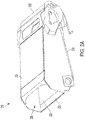
FIGs. 2A and2B are top side isometric views of a reinforced feeder housing for the combine harvester ofFIG. 1 . -
FIG. 3 is a bottom side isometric view of the feeder housing (various features have been omitted for clarity). -
FIG. 4 is a detailed view of the feeder housing as taken fromFIG. 3 . -
FIG. 5 is a detailed view of the feeder housing. -
FIG. 6 is a detailed view of the feeder housing. - Corresponding reference characters indicate corresponding parts throughout the several views. The exemplification set out herein illustrates an embodiment of the invention, in one form, and such exemplification is not to be construed as limiting the scope of the invention in any manner.
- The terms "forward", "rearward", "left" and "right", when used in connection with the agricultural combine and/or components thereof are usually determined with reference to the direction of forward operative travel of the combine, but again, they should not be construed as limiting. The terms "longitudinal" and "transverse" are determined with reference to the fore-and-aft direction of the combine and are equally not to be construed as limiting.
- In
FIG. 1 , acombine harvester 10 has anintake feeder system 12 having a header with acutter 14 and areel 16, a feeder housing (or elevator) 18 and a stone separator 20 arranged between the top of thefeeder housing 18 and thethreshing mechanism 22. The stone separator 20 comprises afeed beater 26, in the form of a rotor with projecting paddles, arranged above arock trap sump 28. Thefeed beater 26 conveys the crop towards thethreshing mechanism 22 while rocks and foreign matter, which are generally heavier and denser than the crop, are impacted and downwardly discharged into the interior of therock trap sump 28. The rotation of thefeed beater 26 propels the rocks and foreign matter downwardly through straw and chaff and into the rock trap sump. As a result, the rocks and foreign matter are separated from the crop prior and prevented from reaching thethreshing mechanism 22. - As noted above, during operation of the combine harvester, various areas of the welded
feeder housing 18 are subject to high stresses, and the high stresses can impact the integrity of the welds of thefeeder housing 18. This effect is most pronounced at locations on thefeeder housing 18 where stiff panels are welded to relatively flexible panels. Described hereinafter is a reinforcedfeeder housing 218 that can better withstand the high stresses of operation. - Referring now to
FIGs. 2A and2B , the reinforcedfeeder housing 218, which may also be referred to herein ashousing 218, comprises a plurality of metal plates that are welded together (or otherwise fastened) in a rectangular hollow box shape. More particularly, thehousing 218 generally includes abottom member 220, atop member 222, and twoside members member housing 218 further includes a front opening 228 through which crop material is directed into thehousing 218 from thereel 16, and arear opening 230 through which crop is expelled from thehousing 218 and is delivered to thethreshing mechanism 22. Various automated devices, such as a conveyor, may or may not be positioned within the interior of thehousing 218 for conveying the crop from the front opening 228 to therear opening 230. As best shown inFIG. 3 , one ormore tubes 232 and arear beam 234 extend between theside members housing 218. A shaft may be positioned within thetube 232. - A
rock trap sump 236 is at least partially formed by across member 238. Thecross member 238 is connected to and extends transversely between theside members cross member 238 may also be connected thebottom member 220. The opening formed by thecross member 238 faces downwardly. In operation, thesump 236 collects rocks and stones, as described above. The stiffness of thecross member 238 is greater than the stiffness of theside members cross member 238. Thecross member 238 may be welded to thebottom member 220 and theside members side members cross member 238 are subject to high stresses for at least the reason that thecross member 238 is structurally stiff whereas theside members - As best shown in
FIG. 4 ,reinforcement brackets 240 are provided to compensate for the high stresses at the welds interconnecting thestiff cross-member 238 and eachflexible side member reinforcement bracket 240 is welded or otherwise attached to (i) at least two interior facing sides of the cross-member 238, and (ii) the interior facing side of theside member 224. Anotherreinforcement bracket 240 is welded or otherwise attached to (i) at least two interior facing sides of the cross-member 238, and (ii) the interior facing side of theside member 226. Thereinforcement bracket 240 is a plate having a first surface for mounting to one of theside members cross member 238, and a third surface for mounting to an orthogonal interior facing side of thecross member 238. The first surface is oriented orthogonal to the second and third surfaces. The second surface is oriented orthogonal to the third surface. Thebracket 240 includes a plurality of elongated slots 242 (three slots shown) and round holes that are used as welding interface surfaces. Thebrackets 240 could also be bolted, or otherwise fastened, to themembers - Referring now to
FIG. 2B , stress concentrations also exist at the welded interface between thefront end 246 of thetop member 222 and theside member 224, as well as the welded interface between thefront end 246 of thetop member 222 and theside member 226. To alleviate the stress concentrations, thefront end 246 of thetop member 222 has a crescent shaped leadingedge 248. Theleading edge 248 may take other shapes. More particularly, the connection ends 250 of theleading edge 248 are positioned closer to the front end 246 (and/or the lower member 220) than thecentral portion 252 of thesurface 248. Relievingsurface 248 at thecentral portion 252 maximizes the size of theopening 228 through which crop material is distributed into thehousing 218, while maximizing the surface area that is available for connection at the connection ends 250. Each of the connection ends 250 is welded, or otherwise fastened, to one of theside members central portion 252, increases the number of possible welds at the connection ends 250, which increases the integrity of the welded connections at the connection ends 250. - Turning now to
FIGs. 3 and5 , stress concentrations also exist at the welded interface between therear beam 234 and theside member 224, as well as the welded interface between therear beam 234 and theside member 226. This is due at least in part because therear beam 234 has a greater rigidity than theflexible side members rear beam 234 is welded, or otherwise fastened, to theside members rear beam 234 is also welded, or otherwise fastened, toadditional side plates rear beam 234 to each side of thehousing 218 at multiple locations along the width 'W' of thehousing 218 increases the integrity of those welds, as well as the integrity of thehousing 218. Theside plate 254 is welded, or otherwise fastened over theside member 224 at multiple locations along the length 'L' of thehousing 218. Similarly, theside plate 256 is welded, or otherwise fastened over theside member 226 at multiple locations along the length 'L' of thehousing 218. Theside plates side members housing 218 between theplate 254 and theside member 224, and another box is formed on one side of thehousing 218 between theplate 256 and theside member 226. - Turning now to
FIGs. 2B and6 , stress concentrations also exist at the welded interface between thefront end 246 of thebottom member 220 and theside member 224, as well as the welded interface between the front end of thebottom member 220 and theside member 226. To alleviate the stress concentrations, thefront end 246 of thebottom member 220 includesopenings 260 that are positioned proximal to or adjacent each of theside members openings 260 may be elongated slots, as shown, or theopenings 260 may take other shapes. In use, theopenings 260 absorb at least a portion of the stress concentrations that typically appear at the welded interface between thefront end 246 of thebottom member 220 and theside member 224, as well as the welded interface between the front end of thebottom member 220 and theside member 226. - In light of all the foregoing, it should thus be apparent to those skilled in the art that there has been shown and described a feeder housing for an agricultural machine, such as a combine harvester. However, it should also be apparent that, within the principles and scope of the invention, many changes are possible and contemplated, including in the details, materials, and arrangements of parts which have been described and illustrated to explain the nature of the invention. Thus, while the foregoing description and discussion addresses certain preferred embodiments or elements of the invention, it should further be understood that concepts of the invention, as based upon the foregoing description and discussion, may be readily incorporated into or employed in other embodiments and constructions without departing from the scope of the invention. Accordingly, the following claims are intended to protect the invention broadly as well as in the specific form shown, and all changes, modifications, variations, and other uses and applications which do not depart from the spirit and scope of the invention are deemed to be covered by the invention, which is limited only by the claims which follow.
Claims (16)
- A feeder housing for an agricultural machine (10), said feeder housing comprising:a housing body (218) comprising a top surface (222), a bottom surface (220), two opposing side surfaces (224, 226) each extending between the top and bottom surfaces, a front opening (218) through which crop material is directed into the feeder housing from a header of the agricultural machine, and a rear opening (230) that is substantially opposite the front opening through which crop is expelled from the feeder housing and is delivered to a threshing mechanism (22) of the agricultural machine;a cross member (238) extending between and either directly or indirectly connecting the opposing side surfaces,characterized in that the feeder housing further comprises:a first bracket (240) that is connected to the cross member (238) and one of the side surfaces (224, 226); anda second bracket (240) that is connected to the cross member (238) and the other of the side surfaces (224, 226).
- The feeder housing of claim 1, characterized in that each bracket (240) is welded to two different surfaces of the cross member (238).
- The feeder housing of any one of the foregoing claims, characterized in that the cross-member (238) comprises at least a portion of a rock trap sump (28) of the feeder housing.
- The feeder housing of any one of the foregoing claims, characterized in that each bracket (240) is welded to the cross member (238) at at least two different locations and is also welded to one of the opposing side surfaces (224, 226).
- The feeder housing of any of the foregoing claims, characterized in that each bracket (240) includes a first surface for mounting to one of the side surfaces (224, 226) and at least two surfaces extending substantially orthogonal to the first surface for mounting to orthogonal surfaces of the cross member (238).
- A feeder housing for an agricultural machine (10), said feeder housing comprising:a housing body (218) comprising a top panel (222), a bottom panel (220), two opposing side panels (224, 226) each extending between the top and bottom panels, a front opening (218) through which crop material is directed into the feeder housing from a header of the agricultural machine, and a rear opening (230) that is substantially opposite the front opening (218) through which crop is expelled from the feeder housing and is delivered to a threshing mechanism (22) of the agricultural machine,characterized in that a leading edge (248) of the top panel that at least partially defines the front opening (218) includes (i) connection ends (250) each of which is connected to one of the side panels (224, 226), and (ii) a central portion (252) extending between the connection ends (250), andwherein the connection ends (250) are positioned forward of the central portion (252) of the leading edge (248).
- The feeder housing of claim 7, characterized in that the central portion of the leading edge is positioned closer to the rear opening (230) than the connection ends of the leading edge.
- The feeder housing of either claim 7 or claim 8, characterized in that the leading edge is crescent shaped.
- The feeder housing of any one of claims 7-9, characterized in that the feeder housing further comprises an opening (260) defined in the bottom panel (220) at a location adjacent a weld between the bottom panel (220) and one of the side panels (224, 226).
- The feeder housing of claim 10, characterized in that the opening (260) is an elongated slot that extends transversely.
- The feeder housing of claim 10 or 11, characterized in that the opening (260) is disposed adjacent the front opening (218) of the housing body (218).
- A feeder housing for an agricultural machine, said feeder housing comprising:a housing body (218) comprising a top surface (222), a bottom surface (220), two opposing side surfaces (224, 226) each extending between the top and bottom surfaces, a front opening (218) through which crop material is directed into the feeder housing from a header of the agricultural machine, and a rear opening (230) that is substantially opposite the front opening through which crop is expelled from the feeder housing and is delivered to a threshing mechanism (22) of the agricultural machine;characterized in that the feeder housing further comprises a cross member (238) disposed at a location adjacent the rear opening (230) and extending between and either directly or indirectly connecting the opposing side surfaces (224, 226), the cross member (238) being connected to each side surface (224, 226) in addition to side panels (254, 256) that are each connected to one of the side surfaces.
- The feeder housing of claim 14, characterized in that one of the side panels (254, 256) is positioned transversely outward from one of the side surfaces (224, 226), and the other side panel (254, 256) is positioned transversely outward from the other side surface (224, 226).
- The feeder housing of claim 15, characterized in that one of the side panels (254, 256) is welded to said one of the side surfaces (224, 226), and the other side panel (254, 256) is welded to the other side surface (224, 226).
- The feeder housing of any one of claims 14-16, characterized in that the cross member (238) is welded to each side surface (224, 226) and each side panel (254, 256).
- The feeder housing of any one of claims 14-17, characterized in that, on each side of the housing body (218), the side surface (224, 226) and the side panel (254, 256) that is connected thereto forms at least a portion of a box.
Applications Claiming Priority (1)
| Application Number | Priority Date | Filing Date | Title |
|---|---|---|---|
| US16/525,746 US11109533B2 (en) | 2019-07-30 | 2019-07-30 | Feeder housing for agricultural machine |
Publications (3)
| Publication Number | Publication Date |
|---|---|
| EP3771325A2 true EP3771325A2 (en) | 2021-02-03 |
| EP3771325A3 EP3771325A3 (en) | 2021-04-21 |
| EP3771325B1 EP3771325B1 (en) | 2024-04-24 |
Family
ID=71783967
Family Applications (1)
| Application Number | Title | Priority Date | Filing Date |
|---|---|---|---|
| EP20187525.9A Active EP3771325B1 (en) | 2019-07-30 | 2020-07-23 | Feeder housing for agricultural machine |
Country Status (3)
| Country | Link |
|---|---|
| US (1) | US11109533B2 (en) |
| EP (1) | EP3771325B1 (en) |
| BR (1) | BR102020015533A2 (en) |
Cited By (1)
| Publication number | Priority date | Publication date | Assignee | Title |
|---|---|---|---|---|
| EP4548745A1 (en) * | 2023-11-06 | 2025-05-07 | Agco do Brasil Solucoes Agricolas LTDA | Feederhouse for a combine harvester |
Families Citing this family (1)
| Publication number | Priority date | Publication date | Assignee | Title |
|---|---|---|---|---|
| JP7685161B2 (en) * | 2023-04-24 | 2025-05-29 | 井関農機株式会社 | combine |
Citations (2)
| Publication number | Priority date | Publication date | Assignee | Title |
|---|---|---|---|---|
| US5882257A (en) | 1997-09-23 | 1999-03-16 | Case Corporation | Rock trap sump door latch |
| US8920226B2 (en) | 2012-05-17 | 2014-12-30 | Cnh Industrial America Llc | Intake feeder system for a combine harvester |
Family Cites Families (20)
| Publication number | Priority date | Publication date | Assignee | Title |
|---|---|---|---|---|
| US3973380A (en) | 1975-07-16 | 1976-08-10 | Deere & Company | Crop feeding mechanism for a harvesting machine |
| US4282703A (en) * | 1979-12-10 | 1981-08-11 | Deere & Company | Feeder house for a crop harvester |
| US4288969A (en) | 1980-03-31 | 1981-09-15 | Sperry Corporation | Stone trap seal |
| US4657029A (en) * | 1986-01-31 | 1987-04-14 | Massey Combines Corporation | Stone trap for a combine harvester |
| US4776153A (en) | 1986-02-27 | 1988-10-11 | Deere & Company | Automatic height control for a laterally pivoted harvester header |
| US5799483A (en) * | 1996-08-29 | 1998-09-01 | Voss; Douglas A. | Combine harvester header lateral levelling |
| US6561342B2 (en) * | 2000-11-29 | 2003-05-13 | Charles Lepage | Granular material conveyor |
| GB2375032A (en) | 2001-04-30 | 2002-11-06 | Ford New Holland Nv | Elevator for an agricultural harvesting machine |
| US6735929B2 (en) * | 2002-03-18 | 2004-05-18 | Deere & Company | Multifunction latch for a combine |
| US6918237B2 (en) * | 2003-07-21 | 2005-07-19 | Cnh America Llc | Feeder position sensor |
| BE1019635A3 (en) * | 2010-02-02 | 2012-09-04 | Cnh Belgium Nv | AGRICULTURAL MACHINE WITH AUTOMATIC COUPLING. |
| BE1019381A3 (en) * | 2010-06-22 | 2012-06-05 | Cnh Belgium Nv | HARVESTING MACHINE WITH AUTOMATIC HYDRAULIC AND ELECTRIC COUPLING FOR A MACHINE. |
| WO2013101863A1 (en) * | 2011-12-28 | 2013-07-04 | Agco Corporation | Fore and aft tilt for corn header |
| US8881495B2 (en) * | 2011-12-28 | 2014-11-11 | Agco Corporation | Front and rear ground sensing for header pitch control |
| US9532497B2 (en) * | 2012-05-02 | 2017-01-03 | Agco Corporation | Variable precharge accumulator for agricultural header |
| DE102012223769A1 (en) * | 2012-12-19 | 2014-06-26 | Deere & Company | Inclined conveyor assembly with improved swing axle |
| US9468148B2 (en) * | 2014-08-29 | 2016-10-18 | Deere & Company | Feederhouse arrangement for mounting a header to a combine |
| US9795084B2 (en) * | 2014-12-12 | 2017-10-24 | AGCO do Brasil | Attachment system for a harvester header |
| JP6640633B2 (en) | 2016-03-28 | 2020-02-05 | 三菱マヒンドラ農機株式会社 | General purpose combine |
| US10426089B2 (en) * | 2016-07-06 | 2019-10-01 | Tribine Industries Llc | Feeder having lateral tilt for an agricultural harvesting combine |
-
2019
- 2019-07-30 US US16/525,746 patent/US11109533B2/en active Active
-
2020
- 2020-07-23 EP EP20187525.9A patent/EP3771325B1/en active Active
- 2020-07-30 BR BR102020015533-4A patent/BR102020015533A2/en unknown
Patent Citations (2)
| Publication number | Priority date | Publication date | Assignee | Title |
|---|---|---|---|---|
| US5882257A (en) | 1997-09-23 | 1999-03-16 | Case Corporation | Rock trap sump door latch |
| US8920226B2 (en) | 2012-05-17 | 2014-12-30 | Cnh Industrial America Llc | Intake feeder system for a combine harvester |
Cited By (1)
| Publication number | Priority date | Publication date | Assignee | Title |
|---|---|---|---|---|
| EP4548745A1 (en) * | 2023-11-06 | 2025-05-07 | Agco do Brasil Solucoes Agricolas LTDA | Feederhouse for a combine harvester |
Also Published As
| Publication number | Publication date |
|---|---|
| EP3771325A3 (en) | 2021-04-21 |
| EP3771325B1 (en) | 2024-04-24 |
| US20210029882A1 (en) | 2021-02-04 |
| US11109533B2 (en) | 2021-09-07 |
| BR102020015533A2 (en) | 2021-02-09 |
Similar Documents
| Publication | Publication Date | Title |
|---|---|---|
| US6922983B2 (en) | Elevator slats for an agricultural harvesting machine | |
| EP2663175B1 (en) | Combine harvester grain cleaning apparatus | |
| EP3818811B1 (en) | Agricultural harvester including a threshing drum with rasp bars having crop egress gaps | |
| CN1895019B (en) | Threshing device | |
| US20230086794A1 (en) | Common drive member for weed seed mill of combine harvester | |
| EP2663176A1 (en) | Combine harvester grain cleaning apparatus | |
| US5125871A (en) | Axial flow combine rotor having helical extension members in forward threshing area | |
| EP3771325B1 (en) | Feeder housing for agricultural machine | |
| US20130310120A1 (en) | Intake feeder system for a combine harvester | |
| EP3217782B1 (en) | Agricultural harvester with a rotated elevator | |
| EP2675267B1 (en) | Crop engaging elements for a combine harvester separating rotor | |
| AU2022224738A1 (en) | Internal drive system for weed seed mill of combine harvester | |
| CN103493645B (en) | The sorting structure of sheller unit and full stalk feed type combine harvester | |
| US10485180B2 (en) | Agricultural harvester auger assembly with crop material deflecting cover | |
| EP4311424B1 (en) | Transitional auger stripper | |
| JP7423499B2 (en) | combine | |
| CN111867357A (en) | combine harvester | |
| CN118252030A (en) | Harvester | |
| CN102239775B (en) | It is mounted with the full stalk feed type combine harvester of sheller unit |
Legal Events
| Date | Code | Title | Description |
|---|---|---|---|
| PUAI | Public reference made under article 153(3) epc to a published international application that has entered the european phase |
Free format text: ORIGINAL CODE: 0009012 |
|
| STAA | Information on the status of an ep patent application or granted ep patent |
Free format text: STATUS: THE APPLICATION HAS BEEN PUBLISHED |
|
| AK | Designated contracting states |
Kind code of ref document: A2 Designated state(s): AL AT BE BG CH CY CZ DE DK EE ES FI FR GB GR HR HU IE IS IT LI LT LU LV MC MK MT NL NO PL PT RO RS SE SI SK SM TR |
|
| AX | Request for extension of the european patent |
Extension state: BA ME |
|
| PUAL | Search report despatched |
Free format text: ORIGINAL CODE: 0009013 |
|
| AK | Designated contracting states |
Kind code of ref document: A3 Designated state(s): AL AT BE BG CH CY CZ DE DK EE ES FI FR GB GR HR HU IE IS IT LI LT LU LV MC MK MT NL NO PL PT RO RS SE SI SK SM TR |
|
| AX | Request for extension of the european patent |
Extension state: BA ME |
|
| RIC1 | Information provided on ipc code assigned before grant |
Ipc: A01F 12/16 20060101AFI20210317BHEP Ipc: A01D 75/18 20060101ALI20210317BHEP |
|
| STAA | Information on the status of an ep patent application or granted ep patent |
Free format text: STATUS: REQUEST FOR EXAMINATION WAS MADE |
|
| 17P | Request for examination filed |
Effective date: 20211021 |
|
| RBV | Designated contracting states (corrected) |
Designated state(s): AL AT BE BG CH CY CZ DE DK EE ES FI FR GB GR HR HU IE IS IT LI LT LU LV MC MK MT NL NO PL PT RO RS SE SI SK SM TR |
|
| STAA | Information on the status of an ep patent application or granted ep patent |
Free format text: STATUS: EXAMINATION IS IN PROGRESS |
|
| 17Q | First examination report despatched |
Effective date: 20221103 |
|
| GRAP | Despatch of communication of intention to grant a patent |
Free format text: ORIGINAL CODE: EPIDOSNIGR1 |
|
| STAA | Information on the status of an ep patent application or granted ep patent |
Free format text: STATUS: GRANT OF PATENT IS INTENDED |
|
| INTG | Intention to grant announced |
Effective date: 20231122 |
|
| RIN1 | Information on inventor provided before grant (corrected) |
Inventor name: ZHAO, KAI Inventor name: MINNICH, MICHAEL Inventor name: JIN, JISHAN Inventor name: FLICKINGER, WAYNE T. Inventor name: BORIACK, CALE |
|
| GRAS | Grant fee paid |
Free format text: ORIGINAL CODE: EPIDOSNIGR3 |
|
| GRAA | (expected) grant |
Free format text: ORIGINAL CODE: 0009210 |
|
| STAA | Information on the status of an ep patent application or granted ep patent |
Free format text: STATUS: THE PATENT HAS BEEN GRANTED |
|
| AK | Designated contracting states |
Kind code of ref document: B1 Designated state(s): AL AT BE BG CH CY CZ DE DK EE ES FI FR GB GR HR HU IE IS IT LI LT LU LV MC MK MT NL NO PL PT RO RS SE SI SK SM TR |
|
| REG | Reference to a national code |
Ref country code: GB Ref legal event code: FG4D |
|
| REG | Reference to a national code |
Ref country code: CH Ref legal event code: EP |
|
| REG | Reference to a national code |
Ref country code: DE Ref legal event code: R096 Ref document number: 602020029431 Country of ref document: DE |
|
| REG | Reference to a national code |
Ref country code: IE Ref legal event code: FG4D |
|
| REG | Reference to a national code |
Ref country code: LT Ref legal event code: MG9D |
|
| REG | Reference to a national code |
Ref country code: NL Ref legal event code: MP Effective date: 20240424 |
|
| REG | Reference to a national code |
Ref country code: AT Ref legal event code: MK05 Ref document number: 1678526 Country of ref document: AT Kind code of ref document: T Effective date: 20240424 |
|
| PG25 | Lapsed in a contracting state [announced via postgrant information from national office to epo] |
Ref country code: NL Free format text: LAPSE BECAUSE OF FAILURE TO SUBMIT A TRANSLATION OF THE DESCRIPTION OR TO PAY THE FEE WITHIN THE PRESCRIBED TIME-LIMIT Effective date: 20240424 |
|
| PG25 | Lapsed in a contracting state [announced via postgrant information from national office to epo] |
Ref country code: NL Free format text: LAPSE BECAUSE OF FAILURE TO SUBMIT A TRANSLATION OF THE DESCRIPTION OR TO PAY THE FEE WITHIN THE PRESCRIBED TIME-LIMIT Effective date: 20240424 |
|
| PG25 | Lapsed in a contracting state [announced via postgrant information from national office to epo] |
Ref country code: IS Free format text: LAPSE BECAUSE OF FAILURE TO SUBMIT A TRANSLATION OF THE DESCRIPTION OR TO PAY THE FEE WITHIN THE PRESCRIBED TIME-LIMIT Effective date: 20240824 |
|
| PG25 | Lapsed in a contracting state [announced via postgrant information from national office to epo] |
Ref country code: BG Free format text: LAPSE BECAUSE OF FAILURE TO SUBMIT A TRANSLATION OF THE DESCRIPTION OR TO PAY THE FEE WITHIN THE PRESCRIBED TIME-LIMIT Effective date: 20240424 |
|
| PG25 | Lapsed in a contracting state [announced via postgrant information from national office to epo] |
Ref country code: FI Free format text: LAPSE BECAUSE OF FAILURE TO SUBMIT A TRANSLATION OF THE DESCRIPTION OR TO PAY THE FEE WITHIN THE PRESCRIBED TIME-LIMIT Effective date: 20240424 Ref country code: HR Free format text: LAPSE BECAUSE OF FAILURE TO SUBMIT A TRANSLATION OF THE DESCRIPTION OR TO PAY THE FEE WITHIN THE PRESCRIBED TIME-LIMIT Effective date: 20240424 |
|
| PG25 | Lapsed in a contracting state [announced via postgrant information from national office to epo] |
Ref country code: GR Free format text: LAPSE BECAUSE OF FAILURE TO SUBMIT A TRANSLATION OF THE DESCRIPTION OR TO PAY THE FEE WITHIN THE PRESCRIBED TIME-LIMIT Effective date: 20240725 |
|
| PG25 | Lapsed in a contracting state [announced via postgrant information from national office to epo] |
Ref country code: PT Free format text: LAPSE BECAUSE OF FAILURE TO SUBMIT A TRANSLATION OF THE DESCRIPTION OR TO PAY THE FEE WITHIN THE PRESCRIBED TIME-LIMIT Effective date: 20240826 |
|
| PG25 | Lapsed in a contracting state [announced via postgrant information from national office to epo] |
Ref country code: ES Free format text: LAPSE BECAUSE OF FAILURE TO SUBMIT A TRANSLATION OF THE DESCRIPTION OR TO PAY THE FEE WITHIN THE PRESCRIBED TIME-LIMIT Effective date: 20240424 |
|
| PG25 | Lapsed in a contracting state [announced via postgrant information from national office to epo] |
Ref country code: AT Free format text: LAPSE BECAUSE OF FAILURE TO SUBMIT A TRANSLATION OF THE DESCRIPTION OR TO PAY THE FEE WITHIN THE PRESCRIBED TIME-LIMIT Effective date: 20240424 |
|
| PG25 | Lapsed in a contracting state [announced via postgrant information from national office to epo] |
Ref country code: PL Free format text: LAPSE BECAUSE OF FAILURE TO SUBMIT A TRANSLATION OF THE DESCRIPTION OR TO PAY THE FEE WITHIN THE PRESCRIBED TIME-LIMIT Effective date: 20240424 |
|
| PG25 | Lapsed in a contracting state [announced via postgrant information from national office to epo] |
Ref country code: LV Free format text: LAPSE BECAUSE OF FAILURE TO SUBMIT A TRANSLATION OF THE DESCRIPTION OR TO PAY THE FEE WITHIN THE PRESCRIBED TIME-LIMIT Effective date: 20240424 |
|
| PG25 | Lapsed in a contracting state [announced via postgrant information from national office to epo] |
Ref country code: PT Free format text: LAPSE BECAUSE OF FAILURE TO SUBMIT A TRANSLATION OF THE DESCRIPTION OR TO PAY THE FEE WITHIN THE PRESCRIBED TIME-LIMIT Effective date: 20240826 Ref country code: PL Free format text: LAPSE BECAUSE OF FAILURE TO SUBMIT A TRANSLATION OF THE DESCRIPTION OR TO PAY THE FEE WITHIN THE PRESCRIBED TIME-LIMIT Effective date: 20240424 Ref country code: NO Free format text: LAPSE BECAUSE OF FAILURE TO SUBMIT A TRANSLATION OF THE DESCRIPTION OR TO PAY THE FEE WITHIN THE PRESCRIBED TIME-LIMIT Effective date: 20240724 Ref country code: LV Free format text: LAPSE BECAUSE OF FAILURE TO SUBMIT A TRANSLATION OF THE DESCRIPTION OR TO PAY THE FEE WITHIN THE PRESCRIBED TIME-LIMIT Effective date: 20240424 Ref country code: IS Free format text: LAPSE BECAUSE OF FAILURE TO SUBMIT A TRANSLATION OF THE DESCRIPTION OR TO PAY THE FEE WITHIN THE PRESCRIBED TIME-LIMIT Effective date: 20240824 Ref country code: HR Free format text: LAPSE BECAUSE OF FAILURE TO SUBMIT A TRANSLATION OF THE DESCRIPTION OR TO PAY THE FEE WITHIN THE PRESCRIBED TIME-LIMIT Effective date: 20240424 Ref country code: GR Free format text: LAPSE BECAUSE OF FAILURE TO SUBMIT A TRANSLATION OF THE DESCRIPTION OR TO PAY THE FEE WITHIN THE PRESCRIBED TIME-LIMIT Effective date: 20240725 Ref country code: FI Free format text: LAPSE BECAUSE OF FAILURE TO SUBMIT A TRANSLATION OF THE DESCRIPTION OR TO PAY THE FEE WITHIN THE PRESCRIBED TIME-LIMIT Effective date: 20240424 Ref country code: ES Free format text: LAPSE BECAUSE OF FAILURE TO SUBMIT A TRANSLATION OF THE DESCRIPTION OR TO PAY THE FEE WITHIN THE PRESCRIBED TIME-LIMIT Effective date: 20240424 Ref country code: BG Free format text: LAPSE BECAUSE OF FAILURE TO SUBMIT A TRANSLATION OF THE DESCRIPTION OR TO PAY THE FEE WITHIN THE PRESCRIBED TIME-LIMIT Effective date: 20240424 Ref country code: AT Free format text: LAPSE BECAUSE OF FAILURE TO SUBMIT A TRANSLATION OF THE DESCRIPTION OR TO PAY THE FEE WITHIN THE PRESCRIBED TIME-LIMIT Effective date: 20240424 Ref country code: RS Free format text: LAPSE BECAUSE OF FAILURE TO SUBMIT A TRANSLATION OF THE DESCRIPTION OR TO PAY THE FEE WITHIN THE PRESCRIBED TIME-LIMIT Effective date: 20240724 |
|
| PG25 | Lapsed in a contracting state [announced via postgrant information from national office to epo] |
Ref country code: DK Free format text: LAPSE BECAUSE OF FAILURE TO SUBMIT A TRANSLATION OF THE DESCRIPTION OR TO PAY THE FEE WITHIN THE PRESCRIBED TIME-LIMIT Effective date: 20240424 |
|
| PG25 | Lapsed in a contracting state [announced via postgrant information from national office to epo] |
Ref country code: EE Free format text: LAPSE BECAUSE OF FAILURE TO SUBMIT A TRANSLATION OF THE DESCRIPTION OR TO PAY THE FEE WITHIN THE PRESCRIBED TIME-LIMIT Effective date: 20240424 |
|
| PG25 | Lapsed in a contracting state [announced via postgrant information from national office to epo] |
Ref country code: CZ Free format text: LAPSE BECAUSE OF FAILURE TO SUBMIT A TRANSLATION OF THE DESCRIPTION OR TO PAY THE FEE WITHIN THE PRESCRIBED TIME-LIMIT Effective date: 20240424 |
|
| PG25 | Lapsed in a contracting state [announced via postgrant information from national office to epo] |
Ref country code: SK Free format text: LAPSE BECAUSE OF FAILURE TO SUBMIT A TRANSLATION OF THE DESCRIPTION OR TO PAY THE FEE WITHIN THE PRESCRIBED TIME-LIMIT Effective date: 20240424 Ref country code: RO Free format text: LAPSE BECAUSE OF FAILURE TO SUBMIT A TRANSLATION OF THE DESCRIPTION OR TO PAY THE FEE WITHIN THE PRESCRIBED TIME-LIMIT Effective date: 20240424 |
|
| REG | Reference to a national code |
Ref country code: DE Ref legal event code: R097 Ref document number: 602020029431 Country of ref document: DE |
|
| PG25 | Lapsed in a contracting state [announced via postgrant information from national office to epo] |
Ref country code: SM Free format text: LAPSE BECAUSE OF FAILURE TO SUBMIT A TRANSLATION OF THE DESCRIPTION OR TO PAY THE FEE WITHIN THE PRESCRIBED TIME-LIMIT Effective date: 20240424 |
|
| PG25 | Lapsed in a contracting state [announced via postgrant information from national office to epo] |
Ref country code: SM Free format text: LAPSE BECAUSE OF FAILURE TO SUBMIT A TRANSLATION OF THE DESCRIPTION OR TO PAY THE FEE WITHIN THE PRESCRIBED TIME-LIMIT Effective date: 20240424 Ref country code: SK Free format text: LAPSE BECAUSE OF FAILURE TO SUBMIT A TRANSLATION OF THE DESCRIPTION OR TO PAY THE FEE WITHIN THE PRESCRIBED TIME-LIMIT Effective date: 20240424 Ref country code: RO Free format text: LAPSE BECAUSE OF FAILURE TO SUBMIT A TRANSLATION OF THE DESCRIPTION OR TO PAY THE FEE WITHIN THE PRESCRIBED TIME-LIMIT Effective date: 20240424 Ref country code: EE Free format text: LAPSE BECAUSE OF FAILURE TO SUBMIT A TRANSLATION OF THE DESCRIPTION OR TO PAY THE FEE WITHIN THE PRESCRIBED TIME-LIMIT Effective date: 20240424 Ref country code: DK Free format text: LAPSE BECAUSE OF FAILURE TO SUBMIT A TRANSLATION OF THE DESCRIPTION OR TO PAY THE FEE WITHIN THE PRESCRIBED TIME-LIMIT Effective date: 20240424 Ref country code: CZ Free format text: LAPSE BECAUSE OF FAILURE TO SUBMIT A TRANSLATION OF THE DESCRIPTION OR TO PAY THE FEE WITHIN THE PRESCRIBED TIME-LIMIT Effective date: 20240424 |
|
| PG25 | Lapsed in a contracting state [announced via postgrant information from national office to epo] |
Ref country code: MC Free format text: LAPSE BECAUSE OF FAILURE TO SUBMIT A TRANSLATION OF THE DESCRIPTION OR TO PAY THE FEE WITHIN THE PRESCRIBED TIME-LIMIT Effective date: 20240424 |
|
| PLBE | No opposition filed within time limit |
Free format text: ORIGINAL CODE: 0009261 |
|
| REG | Reference to a national code |
Ref country code: CH Ref legal event code: PL |
|
| STAA | Information on the status of an ep patent application or granted ep patent |
Free format text: STATUS: NO OPPOSITION FILED WITHIN TIME LIMIT |
|
| PG25 | Lapsed in a contracting state [announced via postgrant information from national office to epo] |
Ref country code: LU Free format text: LAPSE BECAUSE OF NON-PAYMENT OF DUE FEES Effective date: 20240723 |
|
| GBPC | Gb: european patent ceased through non-payment of renewal fee |
Effective date: 20240724 |
|
| PG25 | Lapsed in a contracting state [announced via postgrant information from national office to epo] |
Ref country code: LU Free format text: LAPSE BECAUSE OF NON-PAYMENT OF DUE FEES Effective date: 20240723 |
|
| 26N | No opposition filed |
Effective date: 20250127 |
|
| PG25 | Lapsed in a contracting state [announced via postgrant information from national office to epo] |
Ref country code: SI Free format text: LAPSE BECAUSE OF FAILURE TO SUBMIT A TRANSLATION OF THE DESCRIPTION OR TO PAY THE FEE WITHIN THE PRESCRIBED TIME-LIMIT Effective date: 20240424 Ref country code: CH Free format text: LAPSE BECAUSE OF NON-PAYMENT OF DUE FEES Effective date: 20240731 Ref country code: BE Free format text: LAPSE BECAUSE OF NON-PAYMENT OF DUE FEES Effective date: 20240731 |
|
| PG25 | Lapsed in a contracting state [announced via postgrant information from national office to epo] |
Ref country code: GB Free format text: LAPSE BECAUSE OF NON-PAYMENT OF DUE FEES Effective date: 20240724 |
|
| REG | Reference to a national code |
Ref country code: BE Ref legal event code: MM Effective date: 20240731 |
|
| PG25 | Lapsed in a contracting state [announced via postgrant information from national office to epo] |
Ref country code: IE Free format text: LAPSE BECAUSE OF NON-PAYMENT OF DUE FEES Effective date: 20240723 |
|
| PG25 | Lapsed in a contracting state [announced via postgrant information from national office to epo] |
Ref country code: SE Free format text: LAPSE BECAUSE OF FAILURE TO SUBMIT A TRANSLATION OF THE DESCRIPTION OR TO PAY THE FEE WITHIN THE PRESCRIBED TIME-LIMIT Effective date: 20240424 |
|
| PGFP | Annual fee paid to national office [announced via postgrant information from national office to epo] |
Ref country code: DE Payment date: 20250728 Year of fee payment: 6 |
|
| PGFP | Annual fee paid to national office [announced via postgrant information from national office to epo] |
Ref country code: FR Payment date: 20250725 Year of fee payment: 6 |
|
| PG25 | Lapsed in a contracting state [announced via postgrant information from national office to epo] |
Ref country code: CY Free format text: LAPSE BECAUSE OF FAILURE TO SUBMIT A TRANSLATION OF THE DESCRIPTION OR TO PAY THE FEE WITHIN THE PRESCRIBED TIME-LIMIT; INVALID AB INITIO Effective date: 20200723 Ref country code: IT Free format text: LAPSE BECAUSE OF FAILURE TO SUBMIT A TRANSLATION OF THE DESCRIPTION OR TO PAY THE FEE WITHIN THE PRESCRIBED TIME-LIMIT Effective date: 20240424 |
|
| PG25 | Lapsed in a contracting state [announced via postgrant information from national office to epo] |
Ref country code: HU Free format text: LAPSE BECAUSE OF FAILURE TO SUBMIT A TRANSLATION OF THE DESCRIPTION OR TO PAY THE FEE WITHIN THE PRESCRIBED TIME-LIMIT; INVALID AB INITIO Effective date: 20200723 |