EP3771319A1 - Agricultural implement and control system of such - Google Patents
Agricultural implement and control system of such Download PDFInfo
- Publication number
- EP3771319A1 EP3771319A1 EP20186927.8A EP20186927A EP3771319A1 EP 3771319 A1 EP3771319 A1 EP 3771319A1 EP 20186927 A EP20186927 A EP 20186927A EP 3771319 A1 EP3771319 A1 EP 3771319A1
- Authority
- EP
- European Patent Office
- Prior art keywords
- assembly
- vehicle
- implement
- control
- propulsion
- Prior art date
- Legal status (The legal status is an assumption and is not a legal conclusion. Google has not performed a legal analysis and makes no representation as to the accuracy of the status listed.)
- Pending
Links
Images



Classifications
-
- A—HUMAN NECESSITIES
- A01—AGRICULTURE; FORESTRY; ANIMAL HUSBANDRY; HUNTING; TRAPPING; FISHING
- A01B—SOIL WORKING IN AGRICULTURE OR FORESTRY; PARTS, DETAILS, OR ACCESSORIES OF AGRICULTURAL MACHINES OR IMPLEMENTS, IN GENERAL
- A01B51/00—Undercarriages specially adapted for mounting on various kinds of agricultural tools or apparatus
- A01B51/04—Undercarriages specially adapted for mounting on various kinds of agricultural tools or apparatus drawn by animal or tractor
-
- A—HUMAN NECESSITIES
- A01—AGRICULTURE; FORESTRY; ANIMAL HUSBANDRY; HUNTING; TRAPPING; FISHING
- A01B—SOIL WORKING IN AGRICULTURE OR FORESTRY; PARTS, DETAILS, OR ACCESSORIES OF AGRICULTURAL MACHINES OR IMPLEMENTS, IN GENERAL
- A01B69/00—Steering of agricultural machines or implements; Guiding agricultural machines or implements on a desired track
- A01B69/007—Steering or guiding of agricultural vehicles, e.g. steering of the tractor to keep the plough in the furrow
- A01B69/008—Steering or guiding of agricultural vehicles, e.g. steering of the tractor to keep the plough in the furrow automatic
-
- A—HUMAN NECESSITIES
- A01—AGRICULTURE; FORESTRY; ANIMAL HUSBANDRY; HUNTING; TRAPPING; FISHING
- A01B—SOIL WORKING IN AGRICULTURE OR FORESTRY; PARTS, DETAILS, OR ACCESSORIES OF AGRICULTURAL MACHINES OR IMPLEMENTS, IN GENERAL
- A01B69/00—Steering of agricultural machines or implements; Guiding agricultural machines or implements on a desired track
- A01B69/003—Steering or guiding of machines or implements pushed or pulled by or mounted on agricultural vehicles such as tractors, e.g. by lateral shifting of the towing connection
- A01B69/006—Steering or guiding of machines or implements pushed or pulled by or mounted on agricultural vehicles such as tractors, e.g. by lateral shifting of the towing connection derived from the steering of the tractor
-
- A—HUMAN NECESSITIES
- A01—AGRICULTURE; FORESTRY; ANIMAL HUSBANDRY; HUNTING; TRAPPING; FISHING
- A01C—PLANTING; SOWING; FERTILISING
- A01C7/00—Sowing
-
- B—PERFORMING OPERATIONS; TRANSPORTING
- B62—LAND VEHICLES FOR TRAVELLING OTHERWISE THAN ON RAILS
- B62D—MOTOR VEHICLES; TRAILERS
- B62D11/00—Steering non-deflectable wheels; Steering endless tracks or the like
- B62D11/02—Steering non-deflectable wheels; Steering endless tracks or the like by differentially driving ground-engaging elements on opposite vehicle sides
-
- B—PERFORMING OPERATIONS; TRANSPORTING
- B62—LAND VEHICLES FOR TRAVELLING OTHERWISE THAN ON RAILS
- B62D—MOTOR VEHICLES; TRAILERS
- B62D55/00—Endless track vehicles
- B62D55/06—Endless track vehicles with tracks without ground wheels
- B62D55/065—Multi-track vehicles, i.e. more than two tracks
-
- B—PERFORMING OPERATIONS; TRANSPORTING
- B62—LAND VEHICLES FOR TRAVELLING OTHERWISE THAN ON RAILS
- B62D—MOTOR VEHICLES; TRAILERS
- B62D59/00—Trailers with driven ground wheels or the like
- B62D59/02—Trailers with driven ground wheels or the like driven from external propulsion unit
-
- A—HUMAN NECESSITIES
- A01—AGRICULTURE; FORESTRY; ANIMAL HUSBANDRY; HUNTING; TRAPPING; FISHING
- A01B—SOIL WORKING IN AGRICULTURE OR FORESTRY; PARTS, DETAILS, OR ACCESSORIES OF AGRICULTURAL MACHINES OR IMPLEMENTS, IN GENERAL
- A01B69/00—Steering of agricultural machines or implements; Guiding agricultural machines or implements on a desired track
- A01B69/003—Steering or guiding of machines or implements pushed or pulled by or mounted on agricultural vehicles such as tractors, e.g. by lateral shifting of the towing connection
- A01B69/005—Steering or guiding of machines or implements pushed or pulled by or mounted on agricultural vehicles such as tractors, e.g. by lateral shifting of the towing connection by an additional operator
-
- A—HUMAN NECESSITIES
- A01—AGRICULTURE; FORESTRY; ANIMAL HUSBANDRY; HUNTING; TRAPPING; FISHING
- A01B—SOIL WORKING IN AGRICULTURE OR FORESTRY; PARTS, DETAILS, OR ACCESSORIES OF AGRICULTURAL MACHINES OR IMPLEMENTS, IN GENERAL
- A01B76/00—Parts, details or accessories of agricultural machines or implements, not provided for in groups A01B51/00 - A01B75/00
-
- A—HUMAN NECESSITIES
- A01—AGRICULTURE; FORESTRY; ANIMAL HUSBANDRY; HUNTING; TRAPPING; FISHING
- A01C—PLANTING; SOWING; FERTILISING
- A01C7/00—Sowing
- A01C7/06—Seeders combined with fertilising apparatus
-
- A—HUMAN NECESSITIES
- A01—AGRICULTURE; FORESTRY; ANIMAL HUSBANDRY; HUNTING; TRAPPING; FISHING
- A01C—PLANTING; SOWING; FERTILISING
- A01C7/00—Sowing
- A01C7/20—Parts of seeders for conducting and depositing seed
- A01C7/208—Chassis; Coupling means to a tractor or the like; Lifting means; Side markers
-
- B—PERFORMING OPERATIONS; TRANSPORTING
- B62—LAND VEHICLES FOR TRAVELLING OTHERWISE THAN ON RAILS
- B62D—MOTOR VEHICLES; TRAILERS
- B62D11/00—Steering non-deflectable wheels; Steering endless tracks or the like
- B62D11/001—Steering non-deflectable wheels; Steering endless tracks or the like control systems
-
- B—PERFORMING OPERATIONS; TRANSPORTING
- B62—LAND VEHICLES FOR TRAVELLING OTHERWISE THAN ON RAILS
- B62D—MOTOR VEHICLES; TRAILERS
- B62D13/00—Steering specially adapted for trailers
- B62D13/005—Steering specially adapted for trailers operated from tractor steering system
-
- B—PERFORMING OPERATIONS; TRANSPORTING
- B62—LAND VEHICLES FOR TRAVELLING OTHERWISE THAN ON RAILS
- B62D—MOTOR VEHICLES; TRAILERS
- B62D55/00—Endless track vehicles
- B62D55/08—Endless track units; Parts thereof
Definitions
- the present disclosure relates to agricultural implements, and more particularly to agricultural implements that are moved across an agricultural field by a vehicle.
- an agricultural planter is configured to be moved over a supporting surface by a vehicle.
- the agricultural planter includes a frame and a planter assembly coupled to the frame.
- a first propulsion assembly is coupled to the frame at a first position with the first propulsion assembly having a first traction member configured to engage the supporting surface.
- a second propulsion assembly is coupled to the frame at a second position with the second propulsion assembly having a second traction member configured to engage the supporting surface.
- a drive assembly is operably coupled to at least one of the first or second propulsion assemblies and configured to drive at least one of the first or second traction members during operation of the planter assembly.
- the first traction member is configured to be driven independently of the second traction member.
- the drive assembly is operably coupled to both the first and second propulsion assemblies and configured to drive the first traction member at a first velocity and the second traction member at a second velocity different than the first velocity.
- a control processor is configured to be in communication with the vehicle and the drive assembly and to control the drive assembly to change at least one of the first velocity or the second velocity in response to the vehicle turning in a direction.
- control processor is configured to be in communication with an actuator positioned within a cab of the vehicle, the actuator is separate from a steering wheel of the vehicle, and the actuator is operable to manually change at least one of the first velocity and the second velocity.
- control processor is configured to be in communication with a sensor configured to determine a direction of travel of the agricultural implement, and the control processor is configured to control the drive assembly to change at least one of the first velocity and the second velocity based on the direction of travel of the agricultural implement and a direction of travel of the vehicle.
- the drive assembly includes a hydraulic motor.
- an implement configured to be moved over a supporting surface by a vehicle.
- the implement includes a frame and an implement assembly coupled to the frame and is configured to interact with the supporting surface.
- a first propulsion assembly is coupled to the frame at a first position with the first propulsion assembly having a first traction member configured to engage the supporting surface.
- a second propulsion assembly is coupled to the frame at a second position with the second propulsion assembly having a second traction member configured to engage the supporting surface.
- the first traction member is configured to be driven independently of the second traction member.
- a drive assembly is operably coupled to the first and second propulsion assemblies and configured to drive the first traction member at a first velocity and the second traction member at a second velocity different than the first velocity.
- the drive assembly includes a plurality of hydraulic motors.
- a control processor is configured to be in communication with the drive assembly and a sensor coupled to a steering wheel of the vehicle, and the control processor is configured to control the drive assembly to change at least one of the first velocity and the second velocity in response to a signal generated by the sensor.
- control processor is configured to be in communication with an actuator positioned within a cab of the vehicle, the actuator is separate from a steering wheel of the vehicle, and the actuator is operable to manually change at least one of the first velocity and the second velocity.
- control processor is configured to be in communication with a sensor configured to determine a direction of travel of the implement, and the control processor is configured to control the drive assembly to change at least one of the first velocity and the second velocity based on the direction of travel of the implement and a direction of travel of the vehicle.
- first and second traction members are continuous tracks.
- the implement assembly is a planter assembly configured to dispense agricultural seeds along the surface.
- a control system configured to steer an agricultural implement moveable over a supporting surface by a vehicle.
- the control system includes a first sensor configured to be coupled to a steering wheel of the vehicle configured to determine an angular position of the steering wheel, a drive assembly configured to be coupled to a propulsion assembly of the agricultural implement, and a control processor configured to be in communication with the first sensor and the drive assembly.
- the control processor is configured to receive a steering input from the first sensor, and send a steering output to the drive assembly based on the steering input to control a drive torque to the propulsion assembly.
- an actuator is configured to be positioned within a cab of the vehicle separate from the steering wheel and the control processor is configured to be in communication with the actuator and operable to manually control the drive torque of the propulsion assembly.
- control processor is configured to be in communication with a second sensor configured to determine a direction of travel of the agricultural implement, and the control processor is configured to control the drive assembly based on the direction of travel of the agricultural implement and a direction of travel of the vehicle.
- the drive assembly includes a hydraulic motor.
- a manifold is configured to be positioned between the hydraulic motor and a power generator of the vehicle, and the control processor is coupled to the hydraulic motor to control the drive torque of the propulsion assembly.
- a manifold is configured to be positioned between the hydraulic motor and a power generator of the vehicle, and the control processor is coupled to the manifold to control the drive torque of the propulsion assembly.
- FIG. 1 illustrates an implement (e.g., an agricultural planter 10) coupled to a vehicle 15 to permit the vehicle 15 to pull the planter 10 along a supporting surface 20 (e.g., an agricultural field).
- the implement can be a tillage implement, a sprayer implement, another agricultural implement that is pushed or pulled by the vehicle 15 across the surface 20, or the implement can be a non-agricultural implement (e.g., for use in construction, forestry, etc. applications).
- the vehicle 15 includes a prime mover 25 operable to drive certain wheels 30 of the vehicle 15 to move the vehicle 15 and the planter 10 along or across the surface 20.
- the prime mover 25 is also operable to drive a power generator 35 that supplies the vehicle 15 and the planter 10 with hydraulic power and/or electrical power.
- the power generator 35 can be a hydraulic pump and/or an electric generator.
- the vehicle 15 includes a steering wheel 40 within an operator's cab 45 operable to steer the vehicle 15 in a direction of travel 48 ( FIG. 5 ).
- a sensor 42 is coupled to the steering wheel 40 and is configured to measure an amount the steering wheel 40 is rotated as the vehicle 15 is being steered.
- the illustrated planter 10 includes a frame 50 selectively coupled to a hitch 55 of the vehicle 15, with the frame 50 supported above the surface 20 by wheels 60 and propulsion assemblies 65, to be further discussed in more detail.
- the frame 50 includes a central portion 80 and two wing or outboard portions 85 positioned on opposite sides of the central portion 80.
- the central and outboard portions 80, 85 in combination support planter assemblies 86 positioned along a longitudinal axis 88 defined by a portion of the frame 50.
- the central portion 80 also supports holding tanks 90 that hold planting matter (e.g., seeds) and are in communication with each planter assembly 86 to supply the planter assemblies 86 with the seeds.
- planting matter e.g., seeds
- the wheels 60 are rotatably coupled to the outboard portions 85 and are freely rotatable (e.g., non-drivable wheels).
- the wheels 60 are positioned near ends 92, 94 of the outboard portions 85 as illustrated to support the ends 92, 94 above the surface 20.
- one or more wheels 60 can be coupled to the central portion 80 to at least partially support the central portion 80 above the surface 20.
- the propulsion assemblies 65 include four propulsion assemblies 65a, 65b, 65c, 65d, each coupled to a different location on the central portion 80 of the frame 50 to support the central portion 80 above the surface 20.
- the planter 10 can have fewer than four (e.g., two) propulsion assemblies 65 coupled to the central portion 80.
- the planter 10 can have propulsion assemblies 65 (e.g., two) coupled to the outboard portions 85.
- a first propulsion assembly 65 can be coupled to one of the outboard portions 85 (e.g., adjacent the end 92 of the first outboard portion 85) and a second propulsion assembly 65 can be coupled to the other outboard portion 85 (e.g., adjacent the other end 94 of the second outboard portion 85).
- the planter 10 can have more than four propulsion assemblies 65 total in various configurations supporting portions of the frame 50. All propulsion control of the planter 10 described herein is applicable regardless of number or location of the propulsion assemblies 65.
- propulsion assemblies 65 include similar components, and therefore, only one of the propulsion assemblies 65 will be discussed in detail herein, though the following description is equally applicable to the other propulsion assemblies 65.
- the propulsion assembly 65a includes a bracket 95 pivotably coupled to the frame 50 about a first axis 100, which is substantially parallel to the longitudinal axis 88.
- An actuator such as a hydraulic actuator (e.g., hydraulic actuator 105), is coupled to the frame 50 and the bracket 95 and operable to move the bracket 95 relative to the frame 50 about the first axis 100 to assist in raising or lowering the frame 50 relative to the surface 20.
- the propulsion assembly 65a also includes a traction member (e.g., a continuous or endless member or track 110) that engages the surface 20 and is supported for rotational movement relative to the bracket 95 by a drive wheel 115 and an idler wheel 120.
- a traction member e.g., a continuous or endless member or track 110
- both wheels 115, 120 can be drive wheels, or the wheels 120 can be the drive wheels and the wheels 115 idler wheels.
- another idler wheel 125 is positioned between the two wheels 115, 120 and is operable to bias a bottom portion of the track 110 toward the surface 20.
- the track 110 and the wheels 115, 120, 125 are coupled to a support 130, which is pivotably coupled to the bracket 95 about a second axis 135 substantially parallel to the longitudinal axis 88 of the frame 50.
- the illustrated propulsion assembly 65a is constrained from lateral movement, e.g., movement parallel to the longitudinal axis 88. Stated another way, rotational movement of the track 110 is parallel to a propulsion direction 138 of the planter 10, which is substantially transverse to the longitudinal axis 88.
- the propulsion assembly 65a can, in contrast, selectively pivot in a direction parallel to the longitudinal axis 88.
- the track 110 and the wheels 115, 120, 125 can be replaced with a single wheel driven about an axis (e.g., the second axis 135).
- a drive assembly 140 is operable to drive the propulsion assemblies 65 independently of each other.
- the drive assembly 140 includes a plurality of drive motors 145 (e.g., hydraulic motors, also shown in FIG. 2 ), with each hydraulic motor 145 coupled to one drive wheel 115 of a propulsion assembly 65a, 65b, 65c, 65d.
- each hydraulic motor 145 is supported by the support 130 of one of the propulsion assemblies 65.
- the hydraulic motors 145 are also fluidly coupled (via hydraulic lines 148) to the power generator 35 such that the power generator 35 is operable to supply the hydraulic motors 145 with hydraulic pressure for the application of torque to the drive wheels 115.
- a manifold 150 is positioned fluidly between the hydraulic motors 145 and the power generator 35 such that only two hydraulic lines (e.g., one supply line 148a and one return line 148b) couple the manifold 150 to the power generator 35, and two hydraulic lines (e.g., one supply line 148c and one return line 148d) couple each hydraulic motor 145 to the manifold 150.
- two hydraulic lines e.g., one supply line 148c and one return line 148d
- a control processor 155 is in communication with the hydraulic motors 145 and operable to control each individual hydraulic motor 145 to ultimately control torque provided to the tracks 110 by the corresponding drive wheels 115.
- the illustrated control processor 155 is also in communication with the steering wheel 40 of the vehicle 15 ( FIG. 3 , also FIG. 1 ).
- the control processor 155 is within the vehicle 15. In other embodiments, the control processor 155 can be within or coupled to a portion of the planter 10.
- control processor 155 can be in communication with the manifold 150 rather than with each hydraulic motor 145. As such, the control processor 155 is operable to control each hydraulic motor 145 via the manifold 150, i.e., by controlling the manifold 150 to allow for the desired hydraulic pressure to each hydraulic motor 145.
- the drive motors 145 of the drive assembly 140 can be electric motors in communication with the control processor 155 and electrically coupled to the power generator 35 (e.g., the electric generator) of the vehicle 15.
- the control processor 155 is operable to control each electric motor individually to provide the desired torque to each drive wheel 115 to move each track 110 at a desired speed.
- the illustrated propulsion assemblies 65 assist the vehicle 15 in steering the planter 10 about a desired turn by ultimately controlling an angle 158 between the direction of travel of the vehicle 15 and the propulsion direction 138 of the planter 10.
- the vehicle 15 and the planter 10 are illustrated midway in making a turn (e.g., a 90-degree left hand turn) on the surface 20.
- a turn e.g., a 90-degree left hand turn
- an operator rotates the steering wheel 40 of the vehicle 15 counterclockwise.
- the control processor 155 receives a steering input from the sensor 42 for generating a steering output to the propulsion assemblies 65.
- the control processor 155 receives the steering input from the sensor 42 representative of an angular amount the steering wheel 40 is rotated.
- the steering wheel 40 when the vehicle 15 is tracking straight, the steering wheel 40 is positioned at a 0-degree angle (e.g., 0% rotated) and the sensor 42 generates a signal representative of this position of the steering wheel 40. If the vehicle 40 is steered to the left, the sensor 42 measures the amount the steering wheel 40 is rotated to the left. If the vehicle 40 is steered to the right, the sensor 42 measures the amount the steering wheel 40 is rotated to the right.
- a 0-degree angle e.g., 0% rotated
- the control processor 155 receives the aforementioned steering input from the sensor 42 to then generate the steering output to the propulsion assemblies 65.
- the control processor 155 controls each individual propulsion assembly 65 at a different speed to assist the vehicle 15 to steer the planter 10 through the turn as shown in FIG. 5 .
- the control processor 155 controls the speed of the track 110 of the first propulsion assembly 65a (inner most propulsion assembly 65 relative to the turning radius of the vehicle 15 and the planter 10) at a first velocity.
- the control processor 155 controls the speed of the track 110 of the second propulsion assembly 65b at a second velocity greater than the first velocity.
- the control processor 155 controls the speed of the track 110 of the third propulsion assembly 65c at a third velocity greater than the second velocity.
- control processor 155 controls the speed of the track 110 of the fourth propulsion assembly 65d at a fourth velocity greater than the third velocity, such that the propulsion assemblies 65a, 65b, 65c, and 65d work in concert to accomplish the desired turn based on the steering input of the wheel 40.
- some of the propulsion assemblies 65 can be driven at the same velocity during a turn.
- the first and second propulsion assemblies 65a, 65b can be driven at a first velocity and the third and fourth propulsion assemblies 65c, 65d can be driven at a second velocity different than the first velocity.
- the propulsion assemblies 65 can be driven to assist in movement of the planter 10 along or across the surface 20 even when the vehicle 15 and planter 10 are tracking straight. Alternatively, at least some of the propulsion assemblies 65 can freely rotate (i.e., are nondriven) during movement of the planter 10. For example, certain propulsion assemblies 65 can freely rotate when the vehicle 15 and planter 10 are tracking straight and then engage once the operator of the vehicle 15 begins to move the steering wheel 40.
- the propulsion assemblies 65 can be manually operated using an actuator 160 (e.g., a joystick) positioned within the cab 45 of the vehicle 15 ( FIG. 5 , also FIG. 1 ). Movement of the actuator 160 is received by the control processor 155 to control at least the first propulsion assembly 65a and the fourth propulsion assembly 65d.
- the operator of the vehicle 15 can anticipate a turning operation of the vehicle 15 and the planter 10 and position the planter 10 accordingly for the turning operation. For example, before the vehicle 15 begins to turn as shown in FIG. 5 , the operator of the vehicle 15 can move the actuator 160 in a direction for the propulsion assemblies 65 to move the planter 10 opposite to the turning direction (e.g., to the right within FIG.
- the actuator 160 can be moved while the vehicle 15 is turning (e.g., as shown in FIG. 5 ) such that the propulsion assemblies 65 can further maneuver the planter 10 independently from the steering input from the steering wheel 40.
- control processor 155 and/or the actuator 160 can move at least two different propulsion assemblies 65 in two different rotational directions (e.g., one propulsion assembly 65 in a forward direction and another propulsion assembly 65 in a rearward direction).
- the first propulsion assembly 65a can be driven in a rearward direction and the fourth propulsion assembly 65d can be driven in a forward direction when the steering wheel 40 is rotated to turn the vehicle 15 in the direction as illustrated in FIG. 5 .
- the actuator 160 can be moved while the vehicle 10 is tracking straight for one propulsion assembly 65 to be driven in a forward direction and another propulsion assembly 65 to be driven in a rearward direction.
- the planter 10 also includes a transmitter or sensor 165 coupled to the frame 50 and operable to measure a grade angle 170 of the surface 20 supporting the vehicle 15 and the planter 10.
- the illustrated sensor 165 e.g., a gyroscope
- the grade measuring device can be another type of sensor for measuring the grade angle 170.
- the grade measuring device can be a global positioning system (e.g., GPS) of the vehicle 15 configured to determine the grade angle 170.
- the transmitter 165 is operable to determine the propulsion direction 138 of the planter 10.
- the direction of travel 48 of the vehicle 15 is substantially parallel to the propulsion direction 138 of the planter 10 (i.e., the angle 158 is substantially zero).
- the vehicle 15 and the planter 10 are on the surface 20 with a grade angle 170 (e.g., a 30-degree grade angle), however, and the surface 20 is in a certain condition (e.g., a soft, muddy condition), the weight of the planter 10 can cause the planter 10 to slide down the surface 20 as the vehicle 15 is tracking across the surface 20 such that the angle 158 becomes oblique (e.g., the angle 158 is greater than about 20 degrees). This oblique relationship can negatively affect the planting assemblies 86.
- the illustrated control processor 155 receives a signal from the sensor 165 to generate a tracking output to the propulsion assemblies 65 for assisting the planter 10 in tracking straight with the vehicle 15.
- the control processor 155 can control the propulsion assemblies 65 based on the signal of the sensor 165 independent from the steering input from the steering wheel 40.
- the control processor 155 automatically controls the fourth propulsion assembly 65d (the uphill-most propulsion assembly) at a faster velocity than the other propulsion assemblies 65, i.e. at least assembly 65a, to help maintain the planter 10 tracking straight on the inclined surface 20.
- the velocities of the propulsion assemblies 65 are based on the input signal the control processor 155 receives from the sensor 165.
- the differential between the velocities of the first and fourth propulsion assemblies 65a, 65d may be little to none.
- the controller 155 monitors the angle 158 and controls the propulsion assemblies 65 accordingly to assist the planter 10 in tracking straight with the vehicle 10.
- the control processor 155 is in communication with the steering wheel 40 and the sensor 165 such that the control processor 155 can control the propulsion assemblies 65 as the planter 10 being steered in a direction ( FIG. 5 ) while the planter 10 is concurrently moving along the inclined surface 20 ( FIG. 7 ).
- any combination of inputs from the steering wheel 40, the actuator 160, and the sensor 165 received by the processor 155 are analyzed by the processor 155 to assist in steering control of the planter 10 relative to the vehicle 15 via independent and/or coordinated control of the propulsion assemblies 65.
- the planter 10 can include another sensor in communication with the control processor 155 that measures a surface condition of the surface 20.
- the control processor 155 can control the propulsion assemblies 65 based at least on the surface condition.
- the sensor can determine a relatively hard surface condition of the surface 20, which will promote a relatively small angle 158 while the vehicle 15 is tracking straight across a surface having a relatively large grade angle 170, for the control processor 155 to control the propulsion assemblies 65 accordingly (e.g., at the small velocities).
- the sensor can determine a relatively soft surface condition of the surface 20, which will promote a larger angle 158 while the vehicle 15 is tracking straight across the same surface having the relatively large grade angle 170, for the control processor 155 to control the propulsion assemblies 65 accordingly (e.g., drive one propulsion assembly quicker than another propulsion assembly).
Landscapes
- Life Sciences & Earth Sciences (AREA)
- Engineering & Computer Science (AREA)
- Mechanical Engineering (AREA)
- Soil Sciences (AREA)
- Environmental Sciences (AREA)
- Chemical & Material Sciences (AREA)
- Combustion & Propulsion (AREA)
- Transportation (AREA)
- Zoology (AREA)
- Guiding Agricultural Machines (AREA)
- Control Of Position, Course, Altitude, Or Attitude Of Moving Bodies (AREA)
- Steering Control In Accordance With Driving Conditions (AREA)
- Agricultural Machines (AREA)
- Fertilizing (AREA)
Abstract
Description
- The present disclosure relates to agricultural implements, and more particularly to agricultural implements that are moved across an agricultural field by a vehicle.
- In one aspect, an agricultural planter is configured to be moved over a supporting surface by a vehicle. The agricultural planter includes a frame and a planter assembly coupled to the frame. A first propulsion assembly is coupled to the frame at a first position with the first propulsion assembly having a first traction member configured to engage the supporting surface. A second propulsion assembly is coupled to the frame at a second position with the second propulsion assembly having a second traction member configured to engage the supporting surface. A drive assembly is operably coupled to at least one of the first or second propulsion assemblies and configured to drive at least one of the first or second traction members during operation of the planter assembly. The first traction member is configured to be driven independently of the second traction member.
- In another aspect, the drive assembly is operably coupled to both the first and second propulsion assemblies and configured to drive the first traction member at a first velocity and the second traction member at a second velocity different than the first velocity.
- In another aspect, a control processor is configured to be in communication with the vehicle and the drive assembly and to control the drive assembly to change at least one of the first velocity or the second velocity in response to the vehicle turning in a direction.
- In another aspect, the control processor is configured to be in communication with an actuator positioned within a cab of the vehicle, the actuator is separate from a steering wheel of the vehicle, and the actuator is operable to manually change at least one of the first velocity and the second velocity.
- In another aspect, the control processor is configured to be in communication with a sensor configured to determine a direction of travel of the agricultural implement, and the control processor is configured to control the drive assembly to change at least one of the first velocity and the second velocity based on the direction of travel of the agricultural implement and a direction of travel of the vehicle.
- In another aspect, the drive assembly includes a hydraulic motor.
- In another aspect, an implement is configured to be moved over a supporting surface by a vehicle. The implement includes a frame and an implement assembly coupled to the frame and is configured to interact with the supporting surface. A first propulsion assembly is coupled to the frame at a first position with the first propulsion assembly having a first traction member configured to engage the supporting surface. A second propulsion assembly is coupled to the frame at a second position with the second propulsion assembly having a second traction member configured to engage the supporting surface. The first traction member is configured to be driven independently of the second traction member.
- In another aspect, a drive assembly is operably coupled to the first and second propulsion assemblies and configured to drive the first traction member at a first velocity and the second traction member at a second velocity different than the first velocity.
- In another aspect, the drive assembly includes a plurality of hydraulic motors.
- In another aspect, a control processor is configured to be in communication with the drive assembly and a sensor coupled to a steering wheel of the vehicle, and the control processor is configured to control the drive assembly to change at least one of the first velocity and the second velocity in response to a signal generated by the sensor.
- In another aspect, the control processor is configured to be in communication with an actuator positioned within a cab of the vehicle, the actuator is separate from a steering wheel of the vehicle, and the actuator is operable to manually change at least one of the first velocity and the second velocity.
- In another aspect, the control processor is configured to be in communication with a sensor configured to determine a direction of travel of the implement, and the control processor is configured to control the drive assembly to change at least one of the first velocity and the second velocity based on the direction of travel of the implement and a direction of travel of the vehicle.
- In another aspect, the first and second traction members are continuous tracks.
- In another aspect, the implement assembly is a planter assembly configured to dispense agricultural seeds along the surface.
- In another aspect, a control system is configured to steer an agricultural implement moveable over a supporting surface by a vehicle. The control system includes a first sensor configured to be coupled to a steering wheel of the vehicle configured to determine an angular position of the steering wheel, a drive assembly configured to be coupled to a propulsion assembly of the agricultural implement, and a control processor configured to be in communication with the first sensor and the drive assembly. The control processor is configured to receive a steering input from the first sensor, and send a steering output to the drive assembly based on the steering input to control a drive torque to the propulsion assembly.
- In another aspect, an actuator is configured to be positioned within a cab of the vehicle separate from the steering wheel and the control processor is configured to be in communication with the actuator and operable to manually control the drive torque of the propulsion assembly.
- In another aspect, the control processor is configured to be in communication with a second sensor configured to determine a direction of travel of the agricultural implement, and the control processor is configured to control the drive assembly based on the direction of travel of the agricultural implement and a direction of travel of the vehicle.
- In another aspect, the drive assembly includes a hydraulic motor.
- In another aspect, a manifold is configured to be positioned between the hydraulic motor and a power generator of the vehicle, and the control processor is coupled to the hydraulic motor to control the drive torque of the propulsion assembly.
- In another aspect, a manifold is configured to be positioned between the hydraulic motor and a power generator of the vehicle, and the control processor is coupled to the manifold to control the drive torque of the propulsion assembly.
- Any of the above referenced aspects of the disclosure can be combined with any one or more of the above referenced aspects of the disclosure.
- In addition, other aspects of the disclosure will become apparent by consideration of the detailed description and accompanying drawings.
-
-
FIG. 1 is a perspective view of a vehicle coupled to an agricultural planter. -
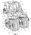
FIG. 2 is a detailed view of propulsion assemblies of the agricultural planter configured to assist the vehicle in steering the agricultural planter. -
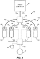
FIG. 3 illustrates a drive assembly according to one embodiment of the disclosure operable to control the propulsion assemblies ofFIG. 2 . -
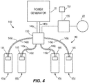
FIG. 4 illustrates a drive assembly according to another embodiment of the disclosure operable to control the propulsion assemblies ofFIG. 2 . -
FIG. 5 is a top view of the vehicle and the agricultural planter ofFIG. 1 turning in a direction. -
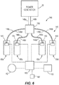
FIG. 6 illustrates a drive assembly according to yet another embodiment of the disclosure operable to control the propulsion assemblies ofFIG. 2 . -
FIG. 7 is a rear view of the vehicle and the agricultural planter ofFIG. 1 moving along an inclined surface. - Before any embodiments of the disclosure are explained in detail, it is to be understood that the disclosure is not limited in its application to the details of construction and the arrangement of components set forth in the following description or illustrated in the following drawings. The disclosure is capable of supporting other embodiments and being practiced or being carried out in various ways. Also, it is to be understood that the phraseology and terminology used herein is for the purpose of description and should not be regarded as limiting. Terms of degree, such as "substantially," "about," "approximately," etc., are understood by those of ordinary skill to refer to reasonable ranges outside of the given value, for example, general tolerances associated with manufacturing, assembly, and use of the described embodiments.
-
FIG. 1 illustrates an implement (e.g., an agricultural planter 10) coupled to avehicle 15 to permit thevehicle 15 to pull theplanter 10 along a supporting surface 20 (e.g., an agricultural field). In other embodiments, the implement can be a tillage implement, a sprayer implement, another agricultural implement that is pushed or pulled by thevehicle 15 across thesurface 20, or the implement can be a non-agricultural implement (e.g., for use in construction, forestry, etc. applications). - The
vehicle 15 includes a prime mover 25 operable to drivecertain wheels 30 of thevehicle 15 to move thevehicle 15 and theplanter 10 along or across thesurface 20. The prime mover 25 is also operable to drive apower generator 35 that supplies thevehicle 15 and theplanter 10 with hydraulic power and/or electrical power. As such, thepower generator 35 can be a hydraulic pump and/or an electric generator. In addition, thevehicle 15 includes asteering wheel 40 within an operator'scab 45 operable to steer thevehicle 15 in a direction of travel 48 (FIG. 5 ). Asensor 42 is coupled to thesteering wheel 40 and is configured to measure an amount thesteering wheel 40 is rotated as thevehicle 15 is being steered. - With further reference to
FIGS. 1 and5 , the illustratedplanter 10 includes aframe 50 selectively coupled to ahitch 55 of thevehicle 15, with theframe 50 supported above thesurface 20 bywheels 60 andpropulsion assemblies 65, to be further discussed in more detail. Theframe 50 includes acentral portion 80 and two wing oroutboard portions 85 positioned on opposite sides of thecentral portion 80. The central andoutboard portions support planter assemblies 86 positioned along alongitudinal axis 88 defined by a portion of theframe 50. Thecentral portion 80 also supportsholding tanks 90 that hold planting matter (e.g., seeds) and are in communication with eachplanter assembly 86 to supply theplanter assemblies 86 with the seeds. - The
wheels 60 are rotatably coupled to theoutboard portions 85 and are freely rotatable (e.g., non-drivable wheels). Thewheels 60 are positioned nearends outboard portions 85 as illustrated to support theends surface 20. In other embodiments, one ormore wheels 60 can be coupled to thecentral portion 80 to at least partially support thecentral portion 80 above thesurface 20. - With continued reference to
FIG. 1 , thepropulsion assemblies 65 include fourpropulsion assemblies central portion 80 of theframe 50 to support thecentral portion 80 above thesurface 20. In other embodiments, theplanter 10 can have fewer than four (e.g., two)propulsion assemblies 65 coupled to thecentral portion 80. In further embodiments, theplanter 10 can have propulsion assemblies 65 (e.g., two) coupled to theoutboard portions 85. For example, afirst propulsion assembly 65 can be coupled to one of the outboard portions 85 (e.g., adjacent theend 92 of the first outboard portion 85) and asecond propulsion assembly 65 can be coupled to the other outboard portion 85 (e.g., adjacent theother end 94 of the second outboard portion 85). In further embodiments, theplanter 10 can have more than fourpropulsion assemblies 65 total in various configurations supporting portions of theframe 50. All propulsion control of theplanter 10 described herein is applicable regardless of number or location of thepropulsion assemblies 65. - All of the
propulsion assemblies 65 include similar components, and therefore, only one of thepropulsion assemblies 65 will be discussed in detail herein, though the following description is equally applicable to theother propulsion assemblies 65. - With reference to
FIG. 2 , thepropulsion assembly 65a includes abracket 95 pivotably coupled to theframe 50 about afirst axis 100, which is substantially parallel to thelongitudinal axis 88. An actuator, such as a hydraulic actuator (e.g., hydraulic actuator 105), is coupled to theframe 50 and thebracket 95 and operable to move thebracket 95 relative to theframe 50 about thefirst axis 100 to assist in raising or lowering theframe 50 relative to thesurface 20. - The
propulsion assembly 65a also includes a traction member (e.g., a continuous or endless member or track 110) that engages thesurface 20 and is supported for rotational movement relative to thebracket 95 by adrive wheel 115 and anidler wheel 120. In other embodiments, bothwheels wheels 120 can be the drive wheels and thewheels 115 idler wheels. As best shown inFIG. 2 , anotheridler wheel 125 is positioned between the twowheels track 110 toward thesurface 20. Thetrack 110 and thewheels support 130, which is pivotably coupled to thebracket 95 about asecond axis 135 substantially parallel to thelongitudinal axis 88 of theframe 50. The illustratedpropulsion assembly 65a is constrained from lateral movement, e.g., movement parallel to thelongitudinal axis 88. Stated another way, rotational movement of thetrack 110 is parallel to apropulsion direction 138 of theplanter 10, which is substantially transverse to thelongitudinal axis 88. In other embodiments, thepropulsion assembly 65a can, in contrast, selectively pivot in a direction parallel to thelongitudinal axis 88. In further embodiments, thetrack 110 and thewheels - With reference to
FIG. 3 , adrive assembly 140 is operable to drive thepropulsion assemblies 65 independently of each other. In particular, thedrive assembly 140 includes a plurality of drive motors 145 (e.g., hydraulic motors, also shown inFIG. 2 ), with eachhydraulic motor 145 coupled to onedrive wheel 115 of apropulsion assembly hydraulic motor 145 is supported by thesupport 130 of one of thepropulsion assemblies 65. Thehydraulic motors 145 are also fluidly coupled (via hydraulic lines 148) to thepower generator 35 such that thepower generator 35 is operable to supply thehydraulic motors 145 with hydraulic pressure for the application of torque to thedrive wheels 115. A manifold 150 is positioned fluidly between thehydraulic motors 145 and thepower generator 35 such that only two hydraulic lines (e.g., onesupply line 148a and onereturn line 148b) couple the manifold 150 to thepower generator 35, and two hydraulic lines (e.g., onesupply line 148c and onereturn line 148d) couple eachhydraulic motor 145 to themanifold 150. - In addition, a
control processor 155 is in communication with thehydraulic motors 145 and operable to control each individualhydraulic motor 145 to ultimately control torque provided to thetracks 110 by the correspondingdrive wheels 115. The illustratedcontrol processor 155 is also in communication with thesteering wheel 40 of the vehicle 15 (FIG. 3 , alsoFIG. 1 ). In the illustrated embodiment, thecontrol processor 155 is within thevehicle 15. In other embodiments, thecontrol processor 155 can be within or coupled to a portion of theplanter 10. - Referring to
FIG. 4 , in further embodiments, thecontrol processor 155 can be in communication with the manifold 150 rather than with eachhydraulic motor 145. As such, thecontrol processor 155 is operable to control eachhydraulic motor 145 via themanifold 150, i.e., by controlling the manifold 150 to allow for the desired hydraulic pressure to eachhydraulic motor 145. - In yet further embodiments, the
drive motors 145 of thedrive assembly 140 can be electric motors in communication with thecontrol processor 155 and electrically coupled to the power generator 35 (e.g., the electric generator) of thevehicle 15. As such, thecontrol processor 155 is operable to control each electric motor individually to provide the desired torque to eachdrive wheel 115 to move eachtrack 110 at a desired speed. - Maneuvering conventional planters about turns (e.g., sharp turns) on the
support surface 20 is difficult due to the width along thelongitudinal axis 88. The illustratedpropulsion assemblies 65 assist thevehicle 15 in steering theplanter 10 about a desired turn by ultimately controlling anangle 158 between the direction of travel of thevehicle 15 and thepropulsion direction 138 of theplanter 10. - With reference to
FIG. 5 , operation thevehicle 15 and theplanter 10 are illustrated midway in making a turn (e.g., a 90-degree left hand turn) on thesurface 20. Accordingly, to make the 90-degree left hand turn, an operator rotates thesteering wheel 40 of thevehicle 15 counterclockwise. In response to this rotation, thecontrol processor 155 receives a steering input from thesensor 42 for generating a steering output to thepropulsion assemblies 65. Specifically, thecontrol processor 155 receives the steering input from thesensor 42 representative of an angular amount thesteering wheel 40 is rotated. For example, when thevehicle 15 is tracking straight, thesteering wheel 40 is positioned at a 0-degree angle (e.g., 0% rotated) and thesensor 42 generates a signal representative of this position of thesteering wheel 40. If thevehicle 40 is steered to the left, thesensor 42 measures the amount thesteering wheel 40 is rotated to the left. If thevehicle 40 is steered to the right, thesensor 42 measures the amount thesteering wheel 40 is rotated to the right. - The
control processor 155 receives the aforementioned steering input from thesensor 42 to then generate the steering output to thepropulsion assemblies 65. In particular, thecontrol processor 155 controls eachindividual propulsion assembly 65 at a different speed to assist thevehicle 15 to steer theplanter 10 through the turn as shown inFIG. 5 . Specifically, thecontrol processor 155 controls the speed of thetrack 110 of thefirst propulsion assembly 65a (innermost propulsion assembly 65 relative to the turning radius of thevehicle 15 and the planter 10) at a first velocity. Thecontrol processor 155 controls the speed of thetrack 110 of thesecond propulsion assembly 65b at a second velocity greater than the first velocity. Thecontrol processor 155 controls the speed of thetrack 110 of thethird propulsion assembly 65c at a third velocity greater than the second velocity. And thecontrol processor 155 controls the speed of thetrack 110 of thefourth propulsion assembly 65d at a fourth velocity greater than the third velocity, such that thepropulsion assemblies wheel 40. - In other embodiments, some of the
propulsion assemblies 65 can be driven at the same velocity during a turn. For example, the first andsecond propulsion assemblies fourth propulsion assemblies - The
propulsion assemblies 65 can be driven to assist in movement of theplanter 10 along or across thesurface 20 even when thevehicle 15 andplanter 10 are tracking straight. Alternatively, at least some of thepropulsion assemblies 65 can freely rotate (i.e., are nondriven) during movement of theplanter 10. For example,certain propulsion assemblies 65 can freely rotate when thevehicle 15 andplanter 10 are tracking straight and then engage once the operator of thevehicle 15 begins to move thesteering wheel 40. - In further embodiments, the
propulsion assemblies 65 can be manually operated using an actuator 160 (e.g., a joystick) positioned within thecab 45 of the vehicle 15 (FIG. 5 , alsoFIG. 1 ). Movement of theactuator 160 is received by thecontrol processor 155 to control at least thefirst propulsion assembly 65a and thefourth propulsion assembly 65d. As such, the operator of thevehicle 15 can anticipate a turning operation of thevehicle 15 and theplanter 10 and position theplanter 10 accordingly for the turning operation. For example, before thevehicle 15 begins to turn as shown inFIG. 5 , the operator of thevehicle 15 can move theactuator 160 in a direction for thepropulsion assemblies 65 to move theplanter 10 opposite to the turning direction (e.g., to the right withinFIG. 5 ) creating a wider turning radius for theplanter 10. By anticipating the movement of the vehicle 15 (e.g., before rotation of the steering wheel 40) and positioning theplanter 10 accordingly, theplanter 10 is more easily maneuvered about a desired turn. Alternatively, theactuator 160 can be moved while thevehicle 15 is turning (e.g., as shown inFIG. 5 ) such that thepropulsion assemblies 65 can further maneuver theplanter 10 independently from the steering input from thesteering wheel 40. - In yet further embodiments, the
control processor 155 and/or theactuator 160 can move at least twodifferent propulsion assemblies 65 in two different rotational directions (e.g., onepropulsion assembly 65 in a forward direction and anotherpropulsion assembly 65 in a rearward direction). For example, thefirst propulsion assembly 65a can be driven in a rearward direction and thefourth propulsion assembly 65d can be driven in a forward direction when thesteering wheel 40 is rotated to turn thevehicle 15 in the direction as illustrated inFIG. 5 . Alternatively, theactuator 160 can be moved while thevehicle 10 is tracking straight for onepropulsion assembly 65 to be driven in a forward direction and anotherpropulsion assembly 65 to be driven in a rearward direction. - With reference to
FIGS. 6 and7 , theplanter 10 also includes a transmitter orsensor 165 coupled to theframe 50 and operable to measure agrade angle 170 of thesurface 20 supporting thevehicle 15 and theplanter 10. The illustrated sensor 165 (e.g., a gyroscope) is in communication with thecontrol processor 155. In other embodiments, the grade measuring device can be another type of sensor for measuring thegrade angle 170. In further embodiments, the grade measuring device can be a global positioning system (e.g., GPS) of thevehicle 15 configured to determine thegrade angle 170. In yet further embodiments, thetransmitter 165 is operable to determine thepropulsion direction 138 of theplanter 10. - In operation, as the
vehicle 15 andplanter 10 track straight along a relatively flat surface (e.g., thegrade angle 170 is about 0-degrees), the direction oftravel 48 of thevehicle 15 is substantially parallel to thepropulsion direction 138 of the planter 10 (i.e., theangle 158 is substantially zero). When thevehicle 15 and theplanter 10 are on thesurface 20 with a grade angle 170 (e.g., a 30-degree grade angle), however, and thesurface 20 is in a certain condition (e.g., a soft, muddy condition), the weight of theplanter 10 can cause theplanter 10 to slide down thesurface 20 as thevehicle 15 is tracking across thesurface 20 such that theangle 158 becomes oblique (e.g., theangle 158 is greater than about 20 degrees). This oblique relationship can negatively affect theplanting assemblies 86. - In such a situation, the illustrated
control processor 155 receives a signal from thesensor 165 to generate a tracking output to thepropulsion assemblies 65 for assisting theplanter 10 in tracking straight with thevehicle 15. As such, thecontrol processor 155 can control thepropulsion assemblies 65 based on the signal of thesensor 165 independent from the steering input from thesteering wheel 40. Referring toFIG. 7 , thecontrol processor 155 automatically controls thefourth propulsion assembly 65d (the uphill-most propulsion assembly) at a faster velocity than theother propulsion assemblies 65, i.e. atleast assembly 65a, to help maintain theplanter 10 tracking straight on theinclined surface 20. The velocities of thepropulsion assemblies 65 are based on the input signal thecontrol processor 155 receives from thesensor 165. For example, under asmall grade angle 170 allowing theangle 158 to be relatively small, the differential between the velocities of the first andfourth propulsion assemblies grade angle 170 increases, which could promote alarger angle 158, the differential between the velocities of the first andfourth propulsion assemblies planter 10 tracking straight. Ultimately, thecontroller 155 monitors theangle 158 and controls thepropulsion assemblies 65 accordingly to assist theplanter 10 in tracking straight with thevehicle 10. - With reference to
FIG. 6 , thecontrol processor 155 is in communication with thesteering wheel 40 and thesensor 165 such that thecontrol processor 155 can control thepropulsion assemblies 65 as theplanter 10 being steered in a direction (FIG. 5 ) while theplanter 10 is concurrently moving along the inclined surface 20 (FIG. 7 ). In other words, any combination of inputs from thesteering wheel 40, theactuator 160, and thesensor 165 received by theprocessor 155 are analyzed by theprocessor 155 to assist in steering control of theplanter 10 relative to thevehicle 15 via independent and/or coordinated control of thepropulsion assemblies 65. In further embodiments, theplanter 10 can include another sensor in communication with thecontrol processor 155 that measures a surface condition of thesurface 20. As such, thecontrol processor 155 can control thepropulsion assemblies 65 based at least on the surface condition. For example, the sensor can determine a relatively hard surface condition of thesurface 20, which will promote a relativelysmall angle 158 while thevehicle 15 is tracking straight across a surface having a relativelylarge grade angle 170, for thecontrol processor 155 to control thepropulsion assemblies 65 accordingly (e.g., at the small velocities). Alternatively, the sensor can determine a relatively soft surface condition of thesurface 20, which will promote alarger angle 158 while thevehicle 15 is tracking straight across the same surface having the relativelylarge grade angle 170, for thecontrol processor 155 to control thepropulsion assemblies 65 accordingly (e.g., drive one propulsion assembly quicker than another propulsion assembly).
Claims (13)
- An agricultural implement (10) configured to be moved over a supporting surface by a vehicle (15), the implement (10) comprising:a frame (50);an implement assembly coupled to the frame (50), the implement assembly configured to interact with the supporting surface;a first propulsion assembly (65, 65a, 65b, 65c, 65d) coupled to the frame (50) at a first position, the first propulsion assembly (65, 65a, 65b, 65c, 65d) including a first traction member (110) configured to engage the supporting surface; anda second propulsion assembly (65, 65a, 65b, 65c, 65d) coupled to the frame (50) at a second position, the second propulsion assembly (65, 65a, 65b, 65c, 65d) including a second traction member (110) configured to engage the supporting surface,wherein the first traction member (110) is configured to be driven independently of the second traction member (110),a drive assembly (140) operably coupled to the first and second propulsion assemblies, wherein the drive assembly (140) is configured to drive the first traction member (110) at a first velocity, and wherein the drive assembly (140) is configured to drive the second traction member (110) at a second velocity different than the first velocity,a control processor (155) configured to be in communication with the drive assembly (140) and a sensor (42) coupled to a steering wheel (40) of the vehicle (15), wherein the control processor (155) is configured to control the drive assembly (140) to change at least one of the first velocity and the second velocity in response to a signal generated by the sensor (42).
- The implement (10) of claim 1, wherein the drive assembly (140) includes a plurality of hydraulic motors.
- The implement (10) of claim 1 or 2, wherein the control processor (155) is configured to be in communication with an actuator (160) positioned within a cab (45) of the vehicle (15), wherein the actuator (160) is separate from the steering wheel (40) of the vehicle (15), and wherein the actuator (160) is operable to manually change at least one of the first velocity and the second velocity.
- The implement (10) of one of the claims 1 to 3, wherein the control processor (155) is configured to be in communication with a sensor (42) configured to determine a direction of travel of the implement (10), and wherein the control processor (155) is configured to control the drive assembly (140) to change at least one of the first velocity and the second velocity based on the direction of travel of the implement (10) and a direction of travel of the vehicle (15).
- The implement (10) of one of the claims 1 to 4, wherein the first and second traction members (110) are continuous tracks.
- The implement (10) of one of the claims 1 to 5, wherein the implement assembly is a planter assembly configured to dispense agricultural seeds along the surface.
- A control system of an agricultural implement (10) according to one of the claims 1 to 6, the control system configured to steer said agricultural implement (10) moveable over a supporting surface by the vehicle (15), the control system comprising:the first sensor (42) configured to be coupled to the steering wheel (40) of the vehicle (15), the first sensor (42) configured to determine an angular position of the steering wheel (40);the drive assembly (140) configured to be coupled to a propulsion assembly (65, 65a, 65b, 65c, 65d) of the agricultural implement (10); andthe control processor (155) configured to be in communication with the first sensor (42) and the drive assembly (140), the control processor (155) configured toreceive a steering input from the first sensor (42), andsend a steering output to the drive assembly (140) based on the steering input to control a drive torque to the propulsion assembly (65, 65a, 65b, 65c, 65d).
- The control system of claim 7, further comprising the actuator (160) configured to be positioned within a cab (45) of the vehicle (15) separate from the steering wheel (40), wherein the control processor (155) is configured to be in communication with the actuator (160) and operable to manually control the drive torque of the propulsion assembly (65, 65a, 65b, 65c, 65d).
- The control system of claim 7 or 8, wherein the control processor (155) is configured to be in communication with a second sensor (165) configured to determine a direction of travel of the agricultural implement (10), and wherein the control processor (155) is configured to control the drive assembly (140) based on the direction of travel of the agricultural implement (10) and a direction of travel of the vehicle (15).
- The control system of one of the clams 7 to 9, wherein the drive assembly (140) includes a hydraulic motor (145).
- The control system of one of the clams 7 to 10, further comprising a manifold (150) configured to be positioned between the hydraulic motor (145) and a power generator (35) of the vehicle (15).
- The control system of one of the clams 7 to 11, wherein the control processor (155) is coupled to the hydraulic motor (145) to control the drive torque of the propulsion assembly (65, 65a, 65b, 65c, 65d).
- The control system of claim 11 or 12, wherein the control processor (155) is coupled to the manifold (150) to control the drive torque of the propulsion assembly (65, 65a, 65b, 65c, 65d).
Applications Claiming Priority (1)
| Application Number | Priority Date | Filing Date | Title |
|---|---|---|---|
| US16/526,548 US11832547B2 (en) | 2019-07-30 | 2019-07-30 | Propulsion assembly for an agricultural implement |
Publications (1)
| Publication Number | Publication Date |
|---|---|
| EP3771319A1 true EP3771319A1 (en) | 2021-02-03 |
Family
ID=72046680
Family Applications (1)
| Application Number | Title | Priority Date | Filing Date |
|---|---|---|---|
| EP20186927.8A Pending EP3771319A1 (en) | 2019-07-30 | 2020-07-21 | Agricultural implement and control system of such |
Country Status (6)
| Country | Link |
|---|---|
| US (2) | US11832547B2 (en) |
| EP (1) | EP3771319A1 (en) |
| AR (1) | AR119245A1 (en) |
| AU (1) | AU2020204262B2 (en) |
| BR (1) | BR102020012429A2 (en) |
| CA (1) | CA3085220A1 (en) |
Cited By (2)
| Publication number | Priority date | Publication date | Assignee | Title |
|---|---|---|---|---|
| WO2024197330A1 (en) * | 2023-03-24 | 2024-10-03 | Croplands Equipment Pty Ltd | A tracked wheel assembly for a boom sprayer |
| EP4552462A1 (en) * | 2023-11-10 | 2025-05-14 | Amazonen-Werke H. Dreyer SE & Co. KG | Agricultural machine with drive device and method for controlling the drive device |
Citations (3)
| Publication number | Priority date | Publication date | Assignee | Title |
|---|---|---|---|---|
| US20150051795A1 (en) * | 2011-09-23 | 2015-02-19 | Deere & Company | Steering control for vehicle trains |
| US9096264B2 (en) * | 2013-03-14 | 2015-08-04 | Cnh Industrial America Llc | Implement carrier with steerable tracks |
| EP3069961A1 (en) * | 2015-03-18 | 2016-09-21 | Deere & Company | Device for assisting the sterring of a vehicle combination |
Family Cites Families (12)
| Publication number | Priority date | Publication date | Assignee | Title |
|---|---|---|---|---|
| US2010110A (en) | 1931-05-20 | 1935-08-06 | Int Harvester Co | Self-propelled planter |
| CA2427416C (en) | 2003-05-01 | 2010-11-16 | 101039130 Saskatchewan Ltd. | Steering device for towed implements |
| US20060090910A1 (en) | 2004-07-20 | 2006-05-04 | Shane Houck | Implement convertible between use configuration and transport configuration |
| US7597172B1 (en) * | 2005-04-22 | 2009-10-06 | Parker-Hannifin Corporation | Gear box for hydraulic energy recovery |
| US8844665B2 (en) * | 2007-12-27 | 2014-09-30 | Swissauto Powersport Llc | Skid steered all terrain vehicle |
| US7849932B2 (en) | 2008-05-01 | 2010-12-14 | Cnh Canada, Ltd. | Steering and elevating wheel system for agricultural implement |
| CA2719664C (en) | 2009-11-04 | 2018-08-07 | David G. Mccrea | Land roller |
| US9421999B2 (en) * | 2014-08-08 | 2016-08-23 | Deere & Company | Charge pressure circuit arrangement for steering control for a vehicle |
| US9706701B2 (en) | 2014-11-19 | 2017-07-18 | Cnh Industrial America Llc | Agricultural implement having power assist wing wheels |
| US9781873B2 (en) | 2014-11-19 | 2017-10-10 | Cnh Industrial America Llc | Agricultural implement having power assist carrier wheels |
| US9926007B2 (en) | 2016-04-07 | 2018-03-27 | Cnh Industrial America Llc | Implement steering system |
| US10455755B2 (en) * | 2017-08-31 | 2019-10-29 | Cnh Industrial America Llc | System and method for strip till implement guidance monitoring and adjustment |
-
2019
- 2019-07-30 US US16/526,548 patent/US11832547B2/en active Active
-
2020
- 2020-06-18 BR BR102020012429-3A patent/BR102020012429A2/en unknown
- 2020-06-24 AR ARP200101793A patent/AR119245A1/en active IP Right Grant
- 2020-06-26 AU AU2020204262A patent/AU2020204262B2/en active Active
- 2020-06-29 CA CA3085220A patent/CA3085220A1/en active Pending
- 2020-07-21 EP EP20186927.8A patent/EP3771319A1/en active Pending
-
2023
- 2023-11-28 US US18/521,311 patent/US20240215472A1/en active Pending
Patent Citations (3)
| Publication number | Priority date | Publication date | Assignee | Title |
|---|---|---|---|---|
| US20150051795A1 (en) * | 2011-09-23 | 2015-02-19 | Deere & Company | Steering control for vehicle trains |
| US9096264B2 (en) * | 2013-03-14 | 2015-08-04 | Cnh Industrial America Llc | Implement carrier with steerable tracks |
| EP3069961A1 (en) * | 2015-03-18 | 2016-09-21 | Deere & Company | Device for assisting the sterring of a vehicle combination |
Cited By (2)
| Publication number | Priority date | Publication date | Assignee | Title |
|---|---|---|---|---|
| WO2024197330A1 (en) * | 2023-03-24 | 2024-10-03 | Croplands Equipment Pty Ltd | A tracked wheel assembly for a boom sprayer |
| EP4552462A1 (en) * | 2023-11-10 | 2025-05-14 | Amazonen-Werke H. Dreyer SE & Co. KG | Agricultural machine with drive device and method for controlling the drive device |
Also Published As
| Publication number | Publication date |
|---|---|
| US11832547B2 (en) | 2023-12-05 |
| US20210029863A1 (en) | 2021-02-04 |
| US20240215472A1 (en) | 2024-07-04 |
| AU2020204262A1 (en) | 2021-02-18 |
| AU2020204262B2 (en) | 2025-08-28 |
| CA3085220A1 (en) | 2021-01-30 |
| AR119245A1 (en) | 2021-12-01 |
| BR102020012429A2 (en) | 2021-02-02 |
Similar Documents
| Publication | Publication Date | Title |
|---|---|---|
| US10745048B2 (en) | Vehicle control systems and methods | |
| US20240215472A1 (en) | Propulsion assembly for an agricultural implement | |
| US9538706B2 (en) | Zero turn mower steering system | |
| US9623903B2 (en) | Steering system and utility vehicle incorporating same | |
| US9168784B2 (en) | Self-propelled windrower tailwheel non-zero caster for stability | |
| US8055411B2 (en) | Steering system and method of steering a machine | |
| US20030019682A1 (en) | ZTR with steerable wheels | |
| AU2012313338B2 (en) | Guidance and control of vehicle travel path and components | |
| AU2009201179B2 (en) | Tractor with automatic steering arrangement | |
| US20210139076A1 (en) | Vehicle Control Systems and Methods and Related Vehicles | |
| US7347293B1 (en) | Work vehicle | |
| US6167982B1 (en) | Steering system for an articulated tracked combine | |
| JP2004057012A (en) | Farm work machine | |
| JPH11291931A (en) | Steering control device for crawler type construction machine and control method therefor | |
| JP2731663B2 (en) | Agricultural work machine steering mechanism | |
| JPS6112744Y2 (en) |
Legal Events
| Date | Code | Title | Description |
|---|---|---|---|
| PUAI | Public reference made under article 153(3) epc to a published international application that has entered the european phase |
Free format text: ORIGINAL CODE: 0009012 |
|
| STAA | Information on the status of an ep patent application or granted ep patent |
Free format text: STATUS: THE APPLICATION HAS BEEN PUBLISHED |
|
| AK | Designated contracting states |
Kind code of ref document: A1 Designated state(s): AL AT BE BG CH CY CZ DE DK EE ES FI FR GB GR HR HU IE IS IT LI LT LU LV MC MK MT NL NO PL PT RO RS SE SI SK SM TR |
|
| AX | Request for extension of the european patent |
Extension state: BA ME |
|
| STAA | Information on the status of an ep patent application or granted ep patent |
Free format text: STATUS: REQUEST FOR EXAMINATION WAS MADE |
|
| 17P | Request for examination filed |
Effective date: 20210803 |
|
| RBV | Designated contracting states (corrected) |
Designated state(s): AL AT BE BG CH CY CZ DE DK EE ES FI FR GB GR HR HU IE IS IT LI LT LU LV MC MK MT NL NO PL PT RO RS SE SI SK SM TR |
|
| STAA | Information on the status of an ep patent application or granted ep patent |
Free format text: STATUS: EXAMINATION IS IN PROGRESS |
|
| 17Q | First examination report despatched |
Effective date: 20230120 |